Lab4实验报告
北邮电子院专业实验报告
电子工程学院ASIC专业实验报告班级:姓名:学号:班内序号:第一部分语言级仿真LAB 1:简单的组合逻辑设计一、实验目的掌握基本组合逻辑电路的实现方法;二、实验原理本实验中描述的是一个可综合的二选一开关,它的功能是当sel = 0时,给出out = a,否则给出结果out = b;在Verilog HDL中,描述组合逻辑时常使用assign结构;equal=a==b1:0是一种在组合逻辑实现分支判断时常用的格式;parameter定义的size参数决定位宽;测试模块用于检测模块设计的是否正确,它给出模块的输入信号,观察模块的内部信号和输出信号;三、源代码module scale_muxout,sel,b,a;parameter size=1;outputsize-1:0 out;inputsize-1:0b,a;input sel;assign out = sela:selb:{size{1'bx}};endmodule`define width 8`timescale 1 ns/1 nsmodule mux_test;reg`width:1a,b;wire`width:1out;reg sel;scale_mux`widthm1.outout,.selsel,.bb,.aa;initialbegin$monitor$stime,,"sel=%b a=%b b=%b out=%b",sel,a,b,out;$dumpvars2,mux_test;sel=0;b={`width{1'b0}};a={`width{1'b1}};5sel=0;b={`width{1'b1}};a={`width{1'b0}};5sel=1;b={`width{1'b0}};a={`width{1'b1}};5sel=1;b={`width{1'b1}};a={`width{1'b0}};5 $finish;endendmodule四、仿真结果与波形LAB 2:简单时序逻辑电路的设计一、实验目的掌握基本时序逻辑电路的实现;二、实验原理在Verilog HDL中,相对于组合逻辑电路,时序逻辑电路也有规定的表述方式;在可综合的Verilog HDL模型中,我们常使用always块和posedge clk或negedge clk的结构来表述时序逻辑;在always块中,被赋值的信号都必须定义为reg型,这是由时序逻辑电路的特点所决定的对于reg 型数据,如果未对它进行赋值,仿真工具会认为它是不定态;为了正确地观察到仿真结果,在可综合的模块中我们通常定义一个复位信号rst-,当它为低电平时对电路中的寄存器进行复位;三、源代码`timescale 1 ns/100 psmodule countercnt,clk,data,rst_,load;output4:0cnt ;input 4:0data;input clk;input rst_;input load;reg 4:0cnt;alwaysposedge clk or negedge rst_ifrst_cnt<=0;elseifloadcnt<=3 data;elsecnt<=4 cnt + 1;endmodule`timescale 1 ns/1 nsmodule counter_test;wire4:0cnt;reg 4:0data;reg rst_;reg load;reg clk;counter c1t cnt,.clk clk,.datadata,.rst_rst_,.loadload;initial beginclk=0;forever begin10 clk=1'b1;10 clk=1'b0;endendinitialbegin$timeformat-9,1,"ns",9;$monitor"time=%t,data=%h,clk=%b,rst_=%b,load=%b,cnt=%b", $stime,data,clk,rst_,load,cnt;$dumpvars2,counter_test;endtask expect;input 4:0expects;ifcnt ==expectsbegin$display"At time %t cnt is %b and should be %b", $time,cnt,expects;$display"TEST FAILED";$finish;endendtaskinitialbeginnegedge clk{rst_,load,data}=7'b0_X_XXXXX;negedge clkexpect5'h00;{rst_,load,data}=7'b1_1_11101;negedge clkexpect5'h1D;{rst_,load,data}=7'b1_0_11101;repeat5negedge clk;expect5'h02;{rst_,load,data}=7'b1_1_11111;negedge clkexpect5'h1F;{rst_,load,data}=7'b0_X_XXXXX;negedge clkexpect5'h00;$display"TEST PASSED";$finish;endendmodule四、仿真结果与波形五、思考题该电路中,rst-是同步还是异步清零端在的always块中reset没有等时钟,而是直接清零;所以是异步清零端;LAB 3:简单时序逻辑电路的设计一、实验目的使用预定义的库元件来设计八位寄存器;二、实验原理八位寄存器中,每一位寄存器由一个二选一MUX和一个触发器dffr组成,当load=1,装载数据;当load=0,寄存器保持;对于处理重复的电路,可用数组条用的方式,使电路描述清晰、简洁; 三、源代码`timescale 1 ns /1 nsmodule clockclk;reg clk;output clk;initial beginclk=0;forever begin10 clk=1'b1;10 clk=1'b0;endendendmodulemux及dffr模块调用代码mux mux7.outn17,.selload,;dffr dffr7 .qout7, .dn17, .clkclk, .rst_rst_ ;mux mux6 .outn16, .selload, .bdata6, .aout6;dffr dffr6 .qout6, .dn16, .clkclk, .rst_rst_ ;mux mux5 .outn15, .selload, .bdata5, .aout5;dffr dffr5 .qout5, .dn15, .clkclk, .rst_rst_ ;mux mux4 .outn14, .selload, .bdata4, .aout4;dffr dffr4 .qout4, .dn14, .clkclk, .rst_rst_ ;.selload, .bdata3, .aout3;dffr dffr3 .qout3, .dn13, .clkclk, .rst_rst_ ;mux mux2 .outn12, .selload, .bdata2, .aout2;dffr dffr2 .qout2, .dn12, .clkclk, .rst_rst_ ;mux mux1 .outn11, .selload, .bdata1, .aout1;dffr dffr1 .qout1, .dn11, .clkclk, .rst_rst_ ;mux mux0 .outn10, .selload, .bdata0, .aout0;dffr dffr0 .qout0, .dn10,;例化寄存器register r1.datadata,.outout,.loadload,.clkclk,.rst_rst_;例化时钟clock c1.clkclk;添加检测信号initialbegin$timeformat-9,1,"ns",9;$monitor"time=%t,clk=%b,data=%h,load=%b,out=%h",$stime,clk,data,load,out;$dumpvars2,register_test;end四、仿真结果与波形LAB 4:用always块实现较复杂的组合逻辑电路一、实验目的掌握用always实现组合逻辑电路的方法;了解assign与always两种组合逻辑电路实现方法之间的区别;二、实验原理仅使用assign结构来实现组合逻辑电路,在设计中会发现很多地方显得冗长且效率低下;适当地使用always来设计组合逻辑,会更具实效;本实验描述的是一个简单的ALU指令译码电路的设计示例;它通过对指令的判断,对输入数据执行相应的操作,包括加、减、或和传数据,并且无论是指令作用的数据还是指令本身发生变化,结果都要做出及时的反应;示例中使用了电平敏感的always块,电平敏感的触发条件是指在后括号内电平列表的任何一个电平发生变化就能触发always块的动作,并且运用了case结构来进行分支判断;在always中适当运用default在case结构中和else子if…else结构中,通常可以综合为纯组合逻辑,尽管被赋值的变量一定要定义为reg型;如果不使用default或else对缺省项进行说明,易产生意想不到的锁存器;三、源代码电路描述alwaysopcode or data or accumbeginifaccum==8'b00000000zero=1;elsezero=0;caseopcodePASS0: out =accum;PASS1: out =accum;ADD: out = data + accum;AND: out =data&accum;XOR: out =data^accum;PASSD: out=data;PASS6: out=accum;PASS7: out=accum;default: out=8'bx;endcaseend四、仿真结果与波形LAB 5:存储器电路的设计一、实验目的设计和测试存储器电路;二、实验原理本实验中,设计一个模块名为mem的存储器仿真模型,该存储器具有双线数据总线及异步处理功能;由于数据是双向的,所以要注意,对memory的读写在时序上要错开;三、源代码自行添加的代码assign data= readmemoryaddr:8'hZ;always posedge writebeginmemoryaddr<=data7:0;end四、仿真结果与波形LAB 6:设计时序逻辑时采用阻塞赋值与非阻塞赋值的区别一、实验目的明确掌握阻塞赋值与非阻塞赋值的概念和区别;了解阻塞赋值的使用情况;二、实验原理在always块中,阻塞赋值可以理解为赋值语句是顺序执行的,而非阻塞赋值可以理解为并发执行的;实际时序逻辑设计中,一般情况下非阻塞赋值语句被更多的使用,有时为了在同一周期实现相互关联的操作,也使用阻塞赋值语句;三、源代码`timescale 1 ns/ 100 psmodule blockingclk,a,b,c;output3:0b,c;input 3:0a;input clk;reg 3:0b,c;alwaysposedge clkbeginb =a;c =b;$display"Blocking: a=%d,b=%d,c=%d.",a,b,c;endendmodule`timescale 1 ns/ 100 psmodule non_blockingclk,a,b,c;output3:0 b,c;input3:0 a;input clk;reg 3:0b,c;always posedge clkbeginb<=a;c<=b;$display"Non_blocking:a=%d,b=%d,c=%d",a,b,c;endendmodule`timescale 1 ns/ 100 psmodule compareTop;wire 3:0 b1,c1,b2,c2;reg3:0a;reg clk;initialbeginclk=0;forever 50 clk=~clk;endinitial$dumpvars 2,compareTop;initialbegina=4'h3;$display"_______________________________";100 a =4'h7;$display"_______________________________";100 a =4'hf;$display"_______________________________";100 a =4'ha;$display"_______________________________";100 a =4'h2;$display"_______________________________";100 $display"_______________________________";$finish;endnon_blocking nonblockingclk,a,b2,c2;blocking blockingclk,a,b1,c1;endmodule四、仿真结果与波形LAB 7:利用有限状态机进行复杂时序逻辑的设计一、实验目的掌握利用有限状态机FSM实现复杂时序逻辑的方法;二、实验原理控制器是CPU的控制核心,用于产生一系列的控制信号,启动或停止某些部件;CPU何时进行读指令,何时进行RAM和I/O端口的读写操作等,都由控制器来控制;三、源代码补充代码nexstate<=state+1'h01;casestate1:begin sel=1;rd=0;ld_ir=0;inc_pc=0;halt=0;ld_pc=0;data_e=0;ld_ac=0;wr=0;end2:begin sel=1;rd=1;ld_ir=0;inc_pc=0;halt=0;ld_pc=0;data_e=0;ld_ac=0;wr=0;end3:begin sel=1;rd=1;ld_ir=1;inc_pc=0;halt=0;ld_pc=0;data_e=0;ld_ac=0;wr=0;end4:begin sel=1;rd=1;ld_ir=1;inc_pc=0;halt=0;ld_pc=0;data_e=0;ld_ac=0;wr=0;end 5:begin sel=0;rd=0;ld_ir=0;inc_pc=1;ld_pc=0;data_e=0;ld_ac=0;wr=0;ifopcode==`HLThalt=1;end6:beginsel=0;rd=alu_op;ld_ir=0;inc_pc=0;halt=0;ld_pc=0;data_e=0;ld_ac=0;wr=0;end7:beginsel=0;rd=alu_op;ld_ir=0;halt=0;data_e=alu_op;ld_ac=0;wr=0;ifopcode==`SKZinc_pc<=zero;ifopcode==`JMPld_pc=1;end0:beginsel=0;rd=alu_op;ld_ir=0;halt=0;data_e=alu_op;ld_ac=alu_op;inc_pc=opcode==`SKZ&zero||opcode==`JMP;ifopcode==`JMPld_pc=1;ifopcode==`STOwr=1;endNo.00000000 No.00000000 No.00000101 No.00000001 // 1C TEMP: //1 temporary variable00000001 // 1D time: // 1 constant 144 - max value 00000110 // 1E LIMIT: // 6 constant 1一、仿真结果与波形第二部分电路综合一、实验目的掌握逻辑综合的概念和流程,熟悉采用Design Compiler进行逻辑综合的基本方法;二、实验内容采用SYNOPSYS公司的综合工具Design Compiler对实验7的做综合;三、源代码与实验指导书中相同;四、门级电路仿真结果与波形五、思考题1.文件是verilog语言及的描述还是结构化的描述是结构化的描述;2.文件中,对触发器的延迟包括哪些信息包括对逻辑单元和管脚的上升/下降时延的最大值、最小值和典型值;第三部分版图设计一、实验目的掌握版图设计的基本概念和流程,熟悉采用Sysnopsys ICC工具进行版图设计的方法;二、实验内容对电路综合输出的门级网表进行布局布线;三、源代码与实验指导书中相同;四、仿真结果与波形布局规划后结果未产生core ring和mesh前产生core ring和mesh后电源线和电影PAD连接后filler PAD填充后布局后结果时钟树综合后结果布线后结果寄生参数的导出和后仿五、思考题1.简述ICC在design setup阶段的主要工作;创建设计库,读取网表文件并创建设计单元,提供并检查时间约束,检查时钟;在对之前的数据与信息进行读取与检查后保存设计单元;2.为什么要填充filler padfiller pad把分散的pad单元连接起来,把pad I/O区域供电连成一个整体;使它们得到持续供电并提高ESD保护能力;3.derive_pg_connection的作用是什么描述有关电源连接的信息;4.简述floorplan的主要任务;对芯片大小、输入输出单元、宏模块进行规划,对电源网络进行设计;5.简述place阶段的主要任务;对电路中的延时进行估计与分析,模拟时钟树的影响,按照时序要求,对标准化单元进行布局;6.简述CTS的主要步骤;设置时钟树公共选项;综合时钟树;重新连接扫描链;使能传播时钟;Post-CTS布局优化;优化时钟偏移;优化时序;实验总结经过数周的ASIC专业实验,我对芯片设计流程、Verilog HDL语言、Linux基本指令和Vi文本编辑器有了基本的了解;虽然之前对芯片设计、VHDL一无所知,但通过实验初步熟悉了ASIC的体系结构和VHDL的基本语法,对电路中时钟、寄生参数、元件布局带来的影响也有了了解;我在实验中也遇到了许多问题,但我在老师、助教、同学的帮助下解决了这些问题,也有了更多收获;通过这次ASIC专业实验,我加深了对本专业的认识;我会继续努力成为合格的电子人;。
实验报告Lab4.c

实验报告课程名称:无线电报系统工程体验实验实验名称:无线电报系统工程体验实验姓名:学院和班级:学号:日期:2016年12月25日概要:通过同学之间发送电报,以及对电报进行干扰与抗干扰处理,已经懂得了电报的基本操作,但是最关心的加密与解密是此次实验的重心。
正文:1.简介本次实验主要任务是对通信系统中的加密解密技术进行简单的体验,并理解通信系统中的安全技术。
同学们会在这次实验中获得关于加密解密技术的直观了解。
2. 理论莫尔斯码;移位代换密码技术;异或代换加密。
3. 实验仪器(工具、设备)本次实验仪器有电键,电报盒子,耳机,对讲机等。
4. 实验步骤任务一:移位代换加密以组为单位,三套设备分别为A、B、C。
其中一套作为无线电报发送端,一套作为无线电报接收端,一套设备作为破译端,进行密码破译。
一套设备选择一条命令。
每套设备轮流作为发送方,接收方,破译方。
例如:A选择命令2,B接收,C破译;B选择命令5,C接收,A 破译;C选择命令1,A接收,B破译。
汉字的对应电码可以查询/,当破译方开始破译时,计时开始,破译完成,计时结束。
1.每套设备成员从表1中选择1条不同的命令。
表1 命令表2. 将命令转换为中文电码,并对电码中的数字进行移位代换。
移位代换的加密过程如下:对给定数值,每一位数字均加上key,0≤key≤9,若移位后的数字大于9,则取其被10除的余数(模10运算)。
例如key=2时,对于给定数值6987,加密后为8109。
本次实验中key的取值范围为:{5,6,7}。
每套设备的成员在该范围内选取一个key值,并对表1中的命令进行加密,将结果记录在表2中。
发送方和接收方事先知道key的具体取值,破译方不知道key的取值,只知道key的范围。
3. 发送无线电命令。
将加密后的电码翻译成莫尔斯码,并通过无线电报发送。
接收方和破译方同时处于接收状态,记录数据。
4. 将收到的莫尔斯码转换为电码,对电码中的数字进行解密,进而得到命令。
Lab4

6 FileI/O
Opening and closing data files. Reading data from and writing data to files. Reading from and writing to spreadsheet-formatted files. Moving and renaming files and directories. Changing file characteristics. Creating, modifying, and reading a configuration file.
1D Array
Waveform graph terminal (1D array)
1D Array
Waveform graph terminal (cluster)
2. Multiple-Plot Waveform Graphs
Build Array function (Array subpalette)
Build Array
1D Arrays
2D array
Waveform graph terminal (2D array)
clusters
cluster array
Waveform graph terminal (cluster array)
5.2 Charts
1. Chart Update Modes
6.2.3 More Writing and Reading of Files
1.Writing and Reading Text Files 可以进行纯文本的读写 Write To Text File Read From Text File 2. Writing and Reading Binary Files
清华大学操作系统课程lab4实验报告

内核线程管理实验报告练习0、合并lab3与lab4的代码还是运用meld合并lab3和lab4,第一次合并之后发生一下错误于是我想lab3这一块都过了,这里怎么会出现问题,跟踪这句话的上一句mm_destroy(mm)发现kfree函数和lab3中的kfree有所不同,这里的kfree出自kmalloc.c,与lab3中的kfree 有很大出入,很可能就是导致这个检查不通过的原因,具体原因没有深究,因为其实这句assert检查代码应该被注释掉,lab4中注释掉了,但合并的过程中我又把注释取消掉了。
将assert注释掉之后,又出现了一个相同的assert问题,原因相同,所以又注释掉了,最后的结果是这样的错误发生在proc.c,说明lab4进入正题了。
练习1、分配并初始化一个进程控制块proc->state = PROC_UNINIT;proc->pid = -1;proc->runs = 0;proc->kstack = 0;proc->need_resched = 0;proc->parent = NULL;proc->mm = NULL;memset(&(proc->context), 0, sizeof(struct context));//初始化进程上下文proc->tf = NULL;//初始化中断帧,用于记录进程发生中断前的状态proc->cr3 = boot_cr3;//因为是内核线程,所以CR3=boot_cr3proc->flags = 0;memset(proc->name, 0, PROC_NAME_LEN);初始化的内容涵盖了除了lisk_link、hash_link以外的所有内容。
可以进一步看看idle进程控制块是怎么设置的:idleproc->pid = 0;idleproc->state = PROC_RUNNABLE;//设置idle状态为运行状态idleproc->kstack = (uintptr_t)bootstack;//idle内核栈的起始地址idleproc->need_resched = 1;//设置需要调度set_proc_name(idleproc, "idle");//设置现成名字nr_process ++;current = idleproc;最后,运行如下图:练习2、为新创建的内核线程分配资源在创建init线程(输出helloworld)的时候,只是用了一下一句话:kernel_thread(init_main, "Hello world!!", 0);//生成一个helloworld线程(1)在讲解do_fork函数之前,有必要讲解kernel_thread()intkernel_thread(int (*fn)(void *), void *arg, uint32_t clone_flags) { struct trapframe tf;memset(&tf, 0, sizeof(struct trapframe));tf.tf_cs = KERNEL_CS;tf.tf_ds = tf.tf_es = tf.tf_ss = KERNEL_DS;tf.tf_regs.reg_ebx= (uint32_t)fn;//设置下次要启动的函数,调度之前ebx 中存有函数地址tf.tf_regs.reg_edx = (uint32_t)arg;//参数,调度之前参数的地址存于edx tf.tf_eip = (uint32_t)kernel_thread_entry;//下次进程运行的位置return do_fork(clone_flags | CLONE_VM, 0, &tf);}它的功能主要是在确定这个新创建的内核线程启动时的位置和环境,有特点的是,启动新创建的线程使用的是中断机制,也就是说现在创建的线程并不会马上开始执行,在后面这个线程将被放到进程列表,进行调度,那个时候才是执行的时候。
Lab04

实验四 RIP路由配置要使互联网络中的每个网络之间能够相互通信,可以使用静态的方式添加和管理路由表,也可以采用动态的方式添加和管理路由表。
本实验学习怎样使用动态路由协议维护和管理路由表,使互联网络能够相互通信。
1.实验目的1)了解动态路由协议;2)理解动态路由协议是怎样维护和管理路由表;3)学习动态路由协议RIP;4)学习RIP的配置方法;5)学会验证RIP路由配置的方法;6)检查网络之间的连通性。
2.实验环境计算机、若干台路由器组成的互联网络或Boson Netsim 6.0路由器、交换机模拟器软件3.实验要求与说明在实验图4-1所示的网络拓扑图中,给每台路由器添加动态路由协议RIP,使每个互联网之间都能够相互通信。
验证RIP的配置,并检查各个网络之间是否能够相互通信。
通过实验,加深对动态路由协议的理解。
实验图4-14.实验步骤(1) 按照实验图4-1所示的网络拓扑图连接网络设备(或在Boson Netsim 中调入网络拓扑图)。
(2) 给每个路由器设置适当的主机名及其他一些基本参数,并给每个路由器和PC机的接口设置如下表所示的IP地址,子网掩码全部为255.255.255.0。
注意,在这里由于路由器之间都是通过Serial接口进行连接的,每一对连接之间,必然有一台路由器充当DCE的角色,要给它设置时钟频率。
我们可以用show controllers命令检查接口是DTE还是DCE。
对充当DCE 的接口设置时钟频率。
(3) 检查路由器两两之间的连通性,如果没有问题,继续进行下面的实验。
(4) 给Router1添加RIP路由协议,并通告相应的网络。
Router1#config tRouter1(config)#router ripRouter1(config-router)#network 10.0.0.0Router1(config-router)#network 172.16.0.0Router1(config-router)#(5) 给Router2添加RIP路由协议,并通告相应的网络。
龙贝格(Romberg)算法的应用实验报告
Lab4 龙贝格(Romberg)算法的应用下面图1中的塑料雨蓬材料是由图2中所示的长方形平板塑料材料压制而成。
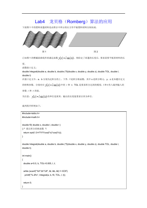
图1 图2已知图1的横截面曲线形状满足函数,则给定了雨蓬的长度后,要求需要平板原材料的长度。
函数接口定义:double Integral(double a, double b, double (*f)(double x, double y, double z), double TOL, double l, double t)在接口定义中:a、b分别为定积分的上、下界,f是积分核函数,其中x是积分哑元,y、z是本题目定义的特殊参数,分别对应中的l和t;TOL是要求积分达到的精度;l和t传入裁判输入的参数l和t的值。
另注意:的单位是厘米,输出的长度值要求以米为单位。
裁判程序样例如下:#include<stdio.h>#include<math.h>double f0( double x, double l, double t ){ /* 弧长积分的核函数*/return sqrt(1.0+l*l*t*t*cos(t*x)*cos(t*x));}double Integral(double a, double b, double (*f)(double x, double y, double z), double TOL, double l, double t);int main(){double a=0.0, b, TOL=0.005, l, t;while (scanf("%lf %lf %lf", &l, &b, &t) != EOF)printf("%.2f\n", Integral(a, b, f0, TOL, l, t));return 0;}裁判输入样例:2 100 1标准输出样例:1.68实验报告:1.求解步骤参照书上的龙贝格求积算法2.步骤①利用k=0;h=b-a;T[0][0]=(h/2)*(f(a,l,t)+f(b,l,t));求解T0(0)3.求解T0(0)到T0(k)的值由公式h=b−an 及h=b−a2k可得n=2k其中h为步长,n为二分次数又由递推公式:T2n=12T n+ℎ2∑f(xk+12)n−1k=0得T2k+1=12T2k+b−a2k+1∑f[a+b−a2k+1(2i−1)]2k−1i=1,k=0,1,2,3~其中xk+12= a+ℎ2(2i−1)。
实验四实现Employee类

报告类型:实验报告□预习报告□报告成绩:__________ 指导教师审核(签名):_______________ 年月日实验四一、实验目的1、学习字符串数据的组织和处理。
2、掌握指针的使用方法。
3、学习使用字符数组和标准C++库处理字符串的方法。
二、题目实现Employee类三、要求1、声明一个Employee类,其中包括表示姓名、街道地址、城市和邮政编码等属性,包括change_name( )和display( )等函数。
2、成员函数display( )使用cout语句显示姓名、街道地址、城市和邮政编码等属性。
3、成员函数change_name( )改变对象的姓名属性,实现并测试这个类。
4、下课前完成实验内容,提交给教师检查。
四、实验步骤1、建立一个控制台应用程序项目lab4,向其中添加一个C++头文件employee.h,在该头文件中编写Employee类的定义。
(方法参照实验二)2、向项目lab4中添加一个C++源文件employee.cpp,在其中实现Employee类。
3、向项目lab4中添加一个C++源文件exp4.cpp,在其中定义main( )函数,测试Employee类,观察程序的执行情况。
一、程序代码:/*在employee.h头文件中进行声明*/#include <iostream>#include <cstring>using namespace std;class employee{private:char name[10]; //姓名char address[20]; //街道地址char city[10]; //城市char post[6]; //邮编public:employee(char[],char[],char[],char[],int);void chang_name(char str[]);void display();};/*在employee.cpp中进行定义*/#include "employee.h"employee::employee(char name_[] ,char address_[],char city_[],char post_[],int num){strcpy(name,name_);strcpy(address,address_);strcpy(city,city_);strcpy(post,post_);}void employee::chang_name(char name_[]){strcpy(name,name_);}void employee::display(){cout<<"姓名:"<<name<<endl;cout<<"街道地址:"<<address<<endl;cout<<"城市:"<<city<<endl;cout<<"邮编:"<<post<<endl;}/*主函数中调用*/#include "employee.h"void main(){cout<<"修改姓名前信息:"<<endl;employee emp("小张","内蒙古工业大学金川","呼和浩特","010080",1);emp.display();cout<<endl;cout<<"修改姓名后信息:"<<endl;emp.chang_name("小李");emp.display();}二、运行结果:。
matlab实验四

(理工类)实验报告书写要求实验报告原则上要求学生手写,要求书写工整。
若因课程特点需打印的,要遵照以下字体、字号、间距等的具体要求。
纸张一律采用A4的纸张。
实验报告书写说明实验报告中一至四项内容为必填项,包括实验目的和要求;实验仪器和设备;实验内容与过程;实验结果与分析。
各院部可根据学科特点和实验具体要求增加项目。
填写注意事项(1)细致观察,及时、准确、如实记录。
(2)准确说明,层次清晰。
(3)尽量采用专用术语来说明事物。
(4)外文、符号、公式要准确,应使用统一规定的名词和符号。
(5)应独立完成实验报告的书写,严禁抄袭、复印,一经发现,以零分论处。
实验报告批改说明实验报告的批改要及时、认真、仔细,一律用红色笔批改。
实验报告的批改成绩采用百分制,具体评分标准由各院部自行制定。
实验报告装订要求实验批改完毕后,任课老师将每门课程的每个实验项目的实验报告以自然班为单位、按学号升序排列,装订成册,并附上一份该门课程的实验大纲。
实验项目名称:MATLAB的符号运算实验学时: 4同组学生姓名:实验地点: C304实验日期: 2012.5.31 6.7 实验成绩:批改教师:批改时间:一、实验目的和要求1、会用MA TLAB求电阻电路。
(节点电压法、戴维南定理等)2、会用MA TLAB求正弦稳态电路。
3、掌握自动控制系统中模型的转换方法。
4、会用MA TLAB求自动控制系统的传递函数。
二、实验仪器和设备计算机一台三、实验过程1、已知条件如下图所示。
求:RL为何值时,能获得最大功率.R L解:分析:把RL用电流源代替(Ia方向从上到下),列节点电压方程,取O为参考点。
经过电路化简,得出关系:Ia=4/3+I2。
列出节点方程:(1/6+1/3+1)U1-U2=I1 {其中I1=12/6=2(A);I2=2(A)}-U1+U2=I2-Ia运用matlab计算出U1,U2的值。
U2即是戴维南等效电路中的Uoc。
令电压源短路,电流源断路,求得ac左边等效电阻Req。
Lab4_合成技术实验
实验四:合成技术实验实验内容简介这个实验开发了使用合成选择使Xilinx FPGA设计获得更好的性能。
验目的完成本次实验后,你能够:1.使用Keep Hierarchy 和the fanout 合成选项来提高调试和合成结果。
2.阅读XST软件合成报告决定合成结果的质量实验步骤你要修改XST合成选项,分析结果。
这个实验主要包括四个步骤:1. 重看设计2. 合成默认选项3. 改变合成选项4. 在RTL浏览器里查看合成结果在以下的实验步骤中,配合每一步操作,我们配有相关的图示。
如果对流程比较熟悉,可以跳过其中的一些操作。
注意:如果在以后你想看这些实验,您可以从Xilinx的大学计划网站/univ上下载相应的文件。
重新看设计和编写软件代码步骤1启动ISE™工程,打开synth_lab.ise.工程文件1.打开Xilinx ISE软件,选择Start → Programs → Xilinx ISE10.1→ Project Navigator2.选择File → Open ProjectVerilog users: Browse to c:\xup\fpgaflowlabs\verilog\lab4VHDL users: Browse to c: \xup\fpgaflow\labs\vhdl\lab43. 选择synth_lab.ise,点击打开更新在lab3中产生的program.psm文件,完成任务#2以显示信息“Xilinx Rules!”建立程序的构架产生程序ROM文件,将ROM文件增加到工程。
1.打开program.psm(在Assembler目录中),如word pad一样,使用统一的标准,增加代码,完成task #2,参考PicoBlaze 架构的技术信息文件。
提示:所有的ASCII 字符都包含在程序顶层的常数列表中,只有两个指令(装载和输出)需要显示一些简单的字符。
2. 打开命令提示,浏览assembler 目录,这个目录里包含了一些最新的程序。
四川大学数据结构实验Lab4_1

四川⼤学数据结构实验Lab4_1Create a Use-Case Diagram4-1Lab 4-1Create a Use-Case DiagramIn this lab, you will model a use-case diagram in the following two ways:An actor and all its use casesOne use case and all its relationshipsYou will also attach flow of events (use-case specifications) to individual use cases and a project artifact that supports the use-case model. Attaching this documentation helps maintain traceability between the use-case model and requirements and can be directly accessed from the Rational Rose tool.Before You BeginDo not begin this lab until you’ve completed the appropriate information in Module 4: The Use-Case Model in the Student Manual.ObjectiveIn Lab 4-1, you ’ll do the following tasks to create the use-case diagrams and attach the supporting artifacts: 1. Add use-case diagrams to the browser. 2. Add actors and use cases to the diagram. 3. Attach use-case flows of events. 4. Attach a project artifact.Fundamentals of Rational Rose Student Workbook4-2Lab OutcomeTwo completed use-case diagrams showing different aspects of the use-case model and important artifacts attached that support the use-case modelLab ArtifactsUse-Case Diagram (Global View) Supporting artifacts (text files) Lab4_1.mdl fileLab4_2.mdl fileFundamentals of Rational Rose Student Workbook Use-Case Diagram (Global View)4-3Fundamentals of Rational Rose Student Workbook4-4Task 1: Add the Use-Case Diagrams to the BrowserWe are using a modified Rational Unified Process framework and have already added our actors and use cases under the Actors and Use Cases packages respectively. Work from the diagram on the previous page.Steps Comments1.Open Lab4_1.mdl. In the browser,expand the Use Case View and then expand the Use-Case Model package. Take a moment to look at the actors under the Actors package and the use cases under the Use Cases package.2. Create two new use-case diagrams underthe Use-Case model package in thebrowser, and name one Realtor View and the other Maintain Personal Planner View .We are creating a use-case diagram that shows a single actor and all its use cases (Realtor actor) and another that shows a single use case and all its relationships(Maintain Personal Planner use case).See the figure below.3. Continue to Task 2 on the next page to add actors and use cases to the use-case diagrams.Fundamentals of Rational Rose Student Workbook4-5Task 2: Add the Actors and Use Cases to DiagramSteps Comments 1. Double-click the Realtor View use-casediagram icon in your browser.The diagram window isopened.2. Using the diagram on page 4-3 or the global use-case diagram in your existing model, determine the use cases associated with the Realtor actor. You may have to expand somepackages to find the actors and use cases that you need.3. Drag the Realtor actor and its use casesfrom the browser into the diagram window. Arrange the diagram accordingly.Notice that the association relationships are also added automatically. We already added these relationships when we created the global use-case diagram.4. Repeat steps 1 through 3 for theMaintain Personal Planner use-case diagram. See the figures below.5. Continue to Task 3 on the next page toadd use-case flows of events.Fundamentals of Rational Rose Student Workbook4-6Task 3: Add Use-Case Flow of EventsWe’ll now attach the following use-case flow of events under the appropriate use-case package.Apply For Loan (ApplyForLoan.txt)Maintain Personal Planner (MaintainPersonalPlanner.txt)Search For A Home (SearchForHome.txt)Steps Comments1. Right-click the Apply for Loan use-casepackage, and then click to select a new file.2. From the Rose2002 directory, select theApplyForLoan.txt file to attach it under the use-case package. You can now double-click the file to open it from Rose. 3. Repeat steps 1 and 2 for the two otheruse-case flows of events. See the figure below.4. Continue to Task 4 on the next page toadd the Problem Statement to the use-case model.Fundamentals of Rational Rose Student Workbook4-7Task 4: Add Project ArtifactAttach the Home Realty System’s Problem Statement (ProblemStatement.txt) to the use-case model. Remember that you want to attach this document to the overall use-case model and not to a specific use case.Leave your model file open for Lab 4-2: Create an Activity Diagram.Try These ActivitiesIf there is time, explore the following features in Rational Rose:Add text to the documentation window to describe one of your use-case diagrams.Change the line and/or fill color of a use case.Return to your Student Manual to discuss activity diagrams. Leave your model file open for Lab 4-2: Create an Activity Diagram.Fundamentals of Rational Rose Student Workbook 4-8。
大学物理实验 4-2实验报告(英文版)
1 0.0512 0.0511
2 0.0511 0.0510
3 0.0513 0.0512
4 0.0512 0.0511
5 0.0515 0.0514
6 0.0513 0.0512
������0 = 0.0001������������ ������������������ =0.0512cm Data analysis: 1.������������ = ������ 2 + ∆2 ������������ = 0.004������������ 2.������������ = 1������������������������ = 5������������������������ = 0.02������������ ������������������ ± ������������ =0.512±0.004mm L± ������������ =83.25±0.5cm D± ������������ = 298.72 ± 1cm l± ������������ = 7.55 ± 0.02cm 3.
������ ������ ������ ∆������
can be known by counting the number of the weights. L can be measuredby the tape; A can be counted by using the microcalliper.∆L is too small to measure directly, we must use the Elastic modulus instrument. Light lever principle is used to measurethe small change amplification. By using reflector we can make the small length change big, in the end, we get E=8DLmg/π������ 2 l(X-������0 ). D is the distance between the reflector and the ruler, l is the length of light leverage. L is the primitive length of the steel, d is the radius of it. Procedure: 1. Adjusting instrument device Adjusting the reflector and then we can see the ruler through the telescope. Adjusting the telescope so that we can see the scale on the ruler clearly. 2. Put eight weights on the hook; write down the X on the ruler
软件测试lab4--使用mujava进行变异测试

软件测试lab4--使⽤mujava进⾏变异测试软件测试技术第四次实验报告⼀、需求分析(描述具体需求)1. 安装MuJava。
2. 根据给定的两个⼩程序使⽤MuJava⽣成对应的变异体。
3. 使⽤Junit给两个程序编写测试集。
4. 使⽤MuJava和测试集测试这些变异体。
⼆、概要设计(简单描述设计思路,配合UML图)1. 设计思路⾸先安装mujava.jar,openjava.jar和junit.jar等需要⽤到的包,在进⾏环境变量的配置,⽣成需要的变异体。
接着编写对应的测试集,再对这些变异体进⾏测试。
三、详细设计(详细描述具体如何实现,附代码及说明)1. 安装MuJava。
将下载好的jar包添加到环境变量中,在CLASSPATH中添加这些jar包的路径,结果如下图所⽰:新建⼀个mujava.config⽂件,并在其中写⼊MuJava_HOME的地址,该地址为新建的MujavaHome的地址。
再新建两个命令脚本⽂件,GenMutants.cmd和RunTest.cmd,在其中分别写⼊如下图所⽰的内容。
2. ⽣成变异体。
先在MujavaHome⽂件夹中新建四个⽂件夹,分别是src,classes,result,testset。
在src⽂件夹中放⼊两个给定的源程序,在classes⽂件夹中放⼊两个源程序在eclipse中编译⽣成的class⽂件。
点击运⾏GenMutants.cmd⽂件,弹出如下图形界⾯,并勾选上所有的变异算⼦。
点击‘Generate’按钮,⽣成变异体,下图分别是BackPack和BubbleSort的变异体:其中,只⽣成了method级别的变异体,没有class级别的变异体。
⽣成变异体后,可以在result⽂件夹内找到⽣成的变异体⽂件。
3. 编写测试⽤例。
(1) backpack的测试⽤例:import org.junit.Assert;import org.junit.After;import org.junit.Before;import org.junit.Test;public class testBackPack {private BackPack c;@Beforepublic void setUp() throws Exception {// setUp()⽤于测试前的初始化c = new BackPack();}@Testpublic void test2() {int m = 10;int n = 3;int w[] = {3, 4, 5};int p[] = {4, 5, 6};int a[][] = {{0, 0, 0, 0, 0, 0, 0, 0, 0, 0, 0},{0, 0, 0, 4, 4, 4, 4, 4, 4, 4, 4},{0, 0, 0, 4, 5, 5, 5, 9, 9, 9, 9},{0, 0, 0, 4, 5, 6, 6, 9, 10, 11, 11}};Assert.assertArrayEquals(a,c.BackPack_Solution(m, n, w, p)); }@Afterpublic void tearDown() throws Exception {// tearDown()⽤于测试后的善后c = null;}}(2) bubblesort的测试⽤例:import static org.junit.Assert.*;import java.util.Arrays;import org.junit.After;import org.junit.Before;import org.junit.Test;public class testBubbleSort {private BubbleSort c;@Beforepublic void setUp() throws Exception {// setUp()⽤于测试前的初始化c = new BubbleSort();}@Testpublic void test1() {int a[] = new int[]{1,6,2,2,5};int b[]=new int[]{2,2,2,1,2,13};int a1[] = new int[]{1,2,2,5,6};int b1[]=new int[]{1,2,2,2,2,13};assertEquals(Arrays.toString(a1), Arrays.toString(c.BubbleSort(a)));assertEquals(Arrays.toString(b1), Arrays.toString(c.BubbleSort(b)));}@Afterpublic void tearDown() throws Exception {// tearDown()⽤于测试后的善后c = null;}}4. 对变异体进⾏测试。
【最新推荐】Lab4实验报告word版本 (9页)
本文部分内容来自网络整理,本司不为其真实性负责,如有异议或侵权请及时联系,本司将立即删除!== 本文为word格式,下载后可方便编辑和修改! ==Lab4实验报告201X简单的类 MIPS 单周期处理器实现–寄存器与内存LAB4 实验报告王红宾 5090519061SJTU | F09051031实验概述1.1实验名称简单的类 MIPS 单周期处理器实现–寄存器与内存1.2 实验目的1.理解 CPU 的寄存器与内存1.3实验范围本次实验将覆盖以下范围1.ISE的使用2.Spartan-3E实验板的使用3.使用Verilog HDL进行逻辑设计4.Register 的实现5.Data Memory 的实现6.有符号扩展的实现1.4注意事项1. 本实验的逻辑设计工具为Xilinx ISE11.1。
2实验内容2.1实验步骤1.启动ISE 11.1。
2.选择File > New Project… 出现New Project Wizard。
3.Project Name填写lab5,选择工程Project Location,Top-level Source Type选择HDL。
点击Next。
4. Device Properties 中各属性填写如下:Product Category: ALLFamily: Spartan3EDevice: XC3S500EPackage: FG320Speed: -4Synthesis Tool: XST(VHDL/Verilog)Simulator: ISim(VHDL/Verilog) ,也可用Modelsim仿真。
Preferred Language: Verilog确认Enable Enhanced Design Summary 已勾选5. 点击Next6. 在New Project Wizard – Create New Source中点击Next7. 在 New Project Wizard – Add Existing Sources中点击Next8. 在New Project Wizard – Project Summary中点击Finish,结束建立工程 3寄存器模块3.1 模块描述寄存器是指令操作的主要对象,MIPS 中一共有 32 个 32 位的寄存器。
实验4

云南大学软件学院实验报告姓名:赵宇学号:20101120128 班级:10级软工日期:2013-5-3 成绩:Lab4 Advanced Database Design一实验任务Lab4a:Design a database to keep track of information for an art museum. Assume that the following requirements were collected:Lab4b:Lame Events puts on athletic events for local athletes. They would like to have a database, including things like the sponsor for the event and where it was located, that can keep track of these events.二实验环境A computer with Microsoft word 2010.三实验结果记录Lab4a:Step 1: TablesStart by identifying three different tables.Figure 1: TablesStep 2: Fields and KeysAdd the fields and designate the primary keys.Figure 2: Fields and KeysStep 3: Recognize Common FieldsMake sure that the fields actually store the same data for each entity.Figure 3: Recognize Common Fields Step 4: Create Supertype/Subtype HierarchyFigure 4: Create Supertype/Subtype HierarchyStep 5: Determine Total/Partial Specialization and Disjoint/Overlap RuleFigure 5: Determine Total/Partial Specialization and Disjoint/Overlap RuleLab4b:Step 1: TablesStart by identifying three different tables.Figure 1: TablesStep 2: Fields and KeysAdd the fields and designate the primary keys.Figure 2: Fields and KeysStep 3: Recognize Common FieldsMake sure that the fields actually store the same data for each entity.Figure 3: Recognize Common Fields Step 4: Create Supertype/Subtype HierarchyFigure 4: Create Supertype/Subtype HierarchyStep 5: Determine Total/Partial Specialization and Disjoint/Overlap RuleFigure 5: Determine Total/Partial Specialization and Disjoint/Overlap Rule 四实验总结通过这次试验,纠正了很多以前错误的认识。
Lab4 模拟输出
Lab 4 模拟输出Lab 4.1 单点模拟输出目标:使用DAQmx API用软件定时的方式输出模拟信号硬件连线:将ELVIS原型板上的AO 0接AI 0+,GROUND接AI 0-实现:创建如下图所示的单点模拟输出的程序框图和前面板(或直接打开练习文件夹中的文件Software-timed analog output.vi)测试:1. 用ELVIS的示波器软面板观察AO 0通道产生的信号:在刚准备好的VI前面板上设置Dev1/ao0作为物理通道(如果在MAX中配置的设备名不是“Dev1”,则选择其他相应的设备名),运行VI,用ELVIS自带的示波器软面板观察产生的电压(注意示波器软面板上的通道Source应设置为AI 0,耦合方式应该设置为DC)模拟输出VI运行时可拖动滑块改变前面板上数值输入控件的值,观察相应的输出变化。
注意此实验我们采用的是软件定时的方式,每次执行DAQmx Write.vi实际只是刷新一次输出。
2. 用Lab3.1中编写好的模拟输入程序来验证模拟输出程序控制下AO 0通道产生的信号:首先停止ELVIS示波器软面板的运行,运行编写好的模拟输出程序,同时运行Lab 3.1中编写的软件定时的模拟输入程序,改变模拟输出程序的输出值,同时观察模拟输入程序中读取到的输入值变化。
Lab 4.2 硬件定时的连续模拟信号输出目标:使用DAQmx API用缓冲区和硬件定时的方式连续输出模拟波形硬件连线:与Lab 4.1相同实现:按下图编写硬件定时连续输出的前面板和程序框图(或直接打开已有程序Hardware-timed Continuous AO.vi)其中“仿真信号Express VI”的配置如下图所示,以产生一个10Hz的三角波信号:测试:1. 运行编写好的硬件定时模拟输出VI2. 通过NI ELVIS的示波器软面板观察AI 0通道的输入,在软面板上设置适当的参数应该可以看到类似下图所示的三角波,这是我们的程序通过AO 0通道产生的波形。
湖南大学计组实验lab4 perflab

课程名称:计算机组成与结构
实验项目名称:perflab
专业班级:
姓名:
学号:
指导教师:
完成时间:2016 年 5 月24 日
信息科学与工程学院
考虑函数的作用,我在第六次小班讨论课上作了分析,所以就引用当时ppt里的内容来分析函数功能:
Pixel是什么?RIDX是什么?
->寻找头文件defs.h(意为:解释,解说)
很容易看出来,这个rotate函数是对一个dim*dim大小的方块作逆时针旋转90度的操作,在这个函数里,每一次操作都是一个单独的“读source”——“写到destination”,的操作,而由于对读source的操作是步长为1的按行读取,因而cache命中率较高,而对于写到destination中的操作是步长为dim的按列读取,因而cache命中率较低,从这个角度考虑,可以交换内外循环的次序进行优化,优先考虑写的操作。
Lab Work 4管理信息系统实验报告

Lab Work 4 Task 1 Automating Repetitive Tasks. 开始一个宏录制设置宏的名称和快捷键:设置文字粗体、斜体以及在每个单元内居中:操作完毕后,结束宏录制查看新录制的宏的信息:查看宏的信息:保存工作簿:工作簿命名为”MonthNames”:创建新的工作簿:按住“Ctrl+Shift+M”,调用宏,得到结果:Task 2 Calculate Tax Values.计算Tax宏函数代码如下:Function tax(price) As Doubletax = price * 0.049End Function运行结果如下:计算Total宏函数代码如下:Function total(price, tax) As Double total = price + taxEnd Function运行结果如下:Task 3.Determine Shipping Charges计算运费宏函数代码如下:Function fee(weight) As DoubleIf weight < 100 Then fee = 100If weight >= 100 And weight < 500 Then fee = weight * 0.5 If weight >= 500 Then fee = weight * 1.00End IfEnd FunctionTask 4 Assess the Letter Grade.评估等级宏函数代码如下:Function lettergrade(grade) As StringSelect Case gradeCase 90 To 100lettergrade = "A"Case 80 To 89lettergrade = "B"Case 70 To 79lettergrade = "C" Case 65 To 69 lettergrade = "D" Case Else lettergrade = "E" End SelectEnd Function运行结果如下:。
- 1、下载文档前请自行甄别文档内容的完整性,平台不提供额外的编辑、内容补充、找答案等附加服务。
- 2、"仅部分预览"的文档,不可在线预览部分如存在完整性等问题,可反馈申请退款(可完整预览的文档不适用该条件!)。
- 3、如文档侵犯您的权益,请联系客服反馈,我们会尽快为您处理(人工客服工作时间:9:00-18:30)。
1.可创建test_for_ signext.v测试文件,添加激励信号,进行行为仿真。
2.在testBench中设定不同的输入。覆盖所有不同控制的情况,多选取一些输入数据,以保证逻辑的正确。
3.打开ISim进行仿真,观察波形是否满足设计逻辑。如果有错,检查代码,重新仿真。
6
6
module register(
begin
readdata2 = regfile[readreg2];
end
always @(negedgeclock_in)
begin
if(regwrite)
regfile[writereg] = writedata;
end
endmodule
6.2 test_for_register
moduletest_for_register;
readreg1 = 0;
readreg2 = 0;
writereg = 0;
writedata = 0;
regwrite = 0;
// current time
#285;
regwrite = 1'b1;
writereg = 5'b10101;
writedata = 32'b11111111111111110000000000000000;
);
reg [31:0] memfile[63:0];
reg [31:0] readdata;
always @(memread)
begin
readdata = memfile[address];
end
always @(negedgeclock_in)
begin
if(memwrite == 1'b1)
wire [31:0] readdata;
parameter DELY = 200;
// Instantiate the Unit Under Test (UUT)
data_memoryuut (
.clock_in(clock_in),
.address(address),
.writedata(writedata),
// Inputs
regclock_in;
reg [25:21] readreg1;
reg [20:16] readreg2;
reg [4:0] writereg;
reg [31:0] writedata;
regregwrite;
// Outputs
wire [31:0] readdata1;
wire [31:0] readdata2;
确认Enable Enhanced Design Summary已勾选
5. 点击Next
6. 在New Project Wizard – Create New Source中点击Next
7. 在 New Project Wizard – Add Existing Sources中点击Next
8. 在New Project Wizard – Project Summary中点击Finish,结束建立工程
writedata = 0;
memwrite = 0;
memread = 0;
// Wait 100 ns for global reset to finish
#185;
memwrite = 1'b1;
address = 15;
writedata = 32'b11111111000000000000000000000000;
.writedata(writedata),
.readdata1(readdata1),
.readdata2(readdata2),
.regwrite(regwrite)
);
always #(DELY/2) clock_in = ~clock_in;
initial begin
clock_in = 0;
memfile[address] = writedata;
end
endmodule
6
moduletest_for_mem;
// Inputs
regclock_in;
reg [31:0] address;
reg [31:0] writedata;
regmemwrite;
regmemread;
// Outputs
// Inputs
reg [15:0] inst;
// Outputs
wire [31:0] data;
// Instantiate the Unit Under Test (UUT)
signextuut (
.inst(inst),
.data(data)
.memwrite(memwrite),
.memread(memread),
.readdata(readdata)
);
always #(DELY/2) clock_in = ~clock_in;
initial begin
// Initialize Inputs
clock_in = 0;
address = 0;
memread = 1'b0;
#250;
memread = 1'b1;
// Add stimulus here
end
endmodule
2.5 signext
modulesignext(
input [15:0] inst,
output [31:0] data
);
reg [31:0] data;
always @(inst)
3.文件类型为Verilog Test Fixture,文件名可取test_for_register
4.Associate Source中选择register,Next。
5.添加激励信号如下图,进行行为仿真。使用clock_in作为时钟输入,仿真周期自定,至少仿真3个周期,这里设为3000ns。时钟周期暂设为200ns。
#200;
writereg = 5'b01010;
writedata = 32'b00000000000000001111111111111111;
#150;
regwrite = 1'b0;
readreg1 = 5'b10101;
readreg2 = 5'b01010;
#100;
regwrite = 1'b1;
1
1.1
简单的类MIPS单周期处理器实现–寄存器与内存
1.2
1.理解CPU的寄存器与内存
1.3
本次实验将覆盖以下范围
1.ISE的使用
2.Spartan-3E实验板的使用
3.使用Verilog HDL进行逻辑设计
4.Register的实现
5.Data Memory的实现
6.有符号扩展的实现
1.4
1.本实验的逻辑设计工具为Xilinx ISE11.1。
inputclock_in,
input [25:21] readreg1,
input [20:16] readreg2,
input [4:0] writereg,
input [31:0] writedata,
output [31:0] readdata1,
output [31:0] readdata2,
// Add stimulus here
end
endmodule
6
moduledata_memory(
inputclock_in,
input [31:0] address,
input [31:0] writedata,
inputmemwrite,
inputmemread,
output [31:0] readdata
begin
if(inst[15] == 0)
assign data = {16'b0000000000000000,inst};
else
assign data = {16'b1111111111111111,inst};
end
endmodule
2.6 test_for_signext
moduletest_for_signext;
(2)负数的补码:符号位为1,其余位为该数绝对值的原码按位取反;然后整个数加1。
求-7的补码。
因为给定数是负数,则符号位为“1”。
后七位:+7的原码(0000111)→按位取反(1111000)→加1(1111001)
所以-7的补码是11111001。
带符号扩展只需要在前面补足符号即可。
5
5.3
将符号补齐
2.添加激励信号如下图,修改代码进行行为仿真。在testBench中设定不同的输入。请覆盖所有的情况,以保证逻辑的正确
3.观察波形是否满足逻辑,如果有错,检查代码,重新仿真。
4.下面给出参考样例:
5
5.1
将16位有符号数扩展为32位有符号数。
补码:
(1)正数的补码:与原码相同。
+9的补码是00001001。
inputregwrite
);
reg [31:0] readdata1;
reg [31:0] readdata2;
reg [31:0] regfile[31:0];
always @(readreg1)
begin
readdata1 = regfile[readreg1];
end
always @(readreg2)
