新格林耐特S2008(16)配置手册
格林耐特2008B+交换机配置应用说明
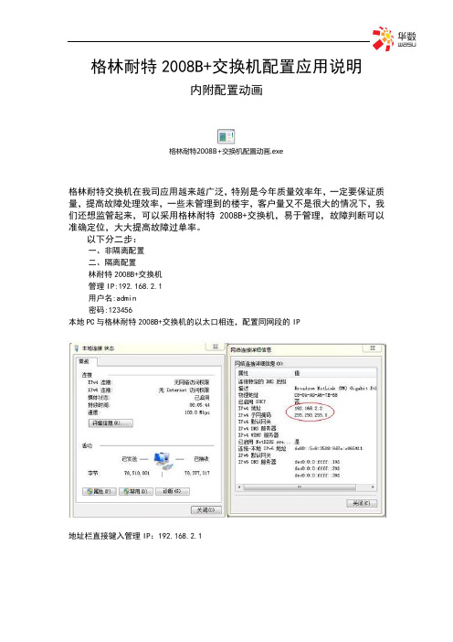
格林耐特2008B+交换机配置应用说明内附配置动画格林耐特2008B+交换机配置动画.exe格林耐特交换机在我司应用越来越广泛,特别是今年质量效率年,一定要保证质量,提高故障处理效率,一些未管理到的楼宇,客户量又不是很大的情况下,我们还想监管起来,可以采用格林耐特2008B+交换机,易于管理,故障判断可以准确定位,大大提高故障过单率。
以下分二步:一、非隔离配置二、隔离配置林耐特2008B+交换机管理IP:192.168.2.1用户名:admin密码:123456本地PC与格林耐特2008B+交换机的以太口相连,配置同网段的IP地址栏直接键入管理IP:192.168.2.1登陆后进入主页面设置密码:jtwhcisco更换可网管IP地址及设置管理VLAN为5以上为交换机管理配置完成一、非隔离配置下面点击VLAN设置下的VLAN模式启用 Change VLAN modePort 08 打TAG标记,定义8口为交换机业务上联VLAN Index NO.从01-1601不能修改,缺省VLAN 1VID:为业务VLAN号,看系统分配的VLAN特别注意:在选择其它VLAN Index NO标记号时都要按一下Read,进行读取。
事例:VLAN标记号为02,1-7口分配业务VLAN1314,非隔离状态,配置如下图。
二、隔离配置隔离配置与非隔离配置有所不同,非隔离配置1个VLAN,1个VLAN标记号即可实现多端口业务应用。
隔离配置需要对每个端口进行分配不同的VLAN标记号才能实现端口隔离。
如:1、2、3、4端口同属VLAN8,相互隔离,配置如下VLAN成员信息。
BST-2008S 操作指南 V1 0
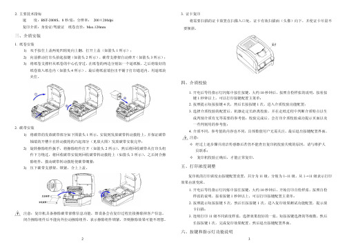
装安卷纸 .1
装安质介、三
。斜倾要 不 量尽卡 证 使 并 �下向 � 像 头 �面描 扫 效 有 卡证� 处 口 入 描 扫在 置 放 卡 证的描 扫 要 需 将 印复卡证 .3 mm021.xaM�径直卷纸 证驶驾/证份身�质介印复 标指术技要主 .2 速 ipd002×002 �率辨分�张/秒 8�S8002-TSB�度
验校质介、四
块纸逼用�内道通印打于铺平出拉端前纸将后最��示所 4 头箭如�内仓纸入放卷纸 。住夹
��示所 3 头箭如�开弹动自架撑支带碳��示所 2 头箭如�键按起抬头印打动推前向 )2 ��示所 1 头箭如�盖上开打�翻上向处陷凹处两盖上住按手双 )1
的好装将后之�板纸逼个一加别分边两的卷纸在�过穿孔心中的卷纸从杆撑支卷纸将 )3
�辊胶和 SIC 洁清骤步述上按天每 。印复始开后发挥全完精酒待�后钟分 01―5 �尘灰的面表器感传射透印打、辊胶印打、头印打除擦球棉精酒的干拧用 �架撑支带碳起抬�盖上开打 表器感传射透描扫及辊胶纸出、辊胶纸进、SIC 下、上除擦球棉精酒的干拧用 �盖上描扫开打�源电机印复闭关 �尘灰的面
�
�
辊胶纸出○ 8 盖上描扫○ 6 灯示指源电○ 4 灯示指障故○ 3 键按○ 2 盖上○ 1 关开源电○ 5
组头印打从带碳收回将后然� �示所 2 头箭如�开打件组除擦将�手扳件组除擦转旋 )2 �毕完装安带碳放发�图大放见�分部起凸的轮拨动转在卡槽开的端轴
带碳证保并�上轮拨动转带碳放发到装安�示所 1 头箭图下如分部带碳放发的带碳将 )1
装安带碳 .2
按着按�明说的张样检自照按�后钟秒 01 约大�键按住按中烁闪灯示指待等后电开 .1
3
2
明说能功灯示指和键按、六
Schneider Electric TeSys产品数据手册说明书

T h e i n f o r m a t i o n p r o v i d e d i n t h i s d o c u m e n t a t i o n c o n t a i n s g e n e r a l d e s c r i p t i o n s a n d /o r t e c h n i c a l c h a r a c t e r i s t i c s o f t h e p e r f o r m a n c e o f t h e p r o d u c t s c o n t a i n e d h e r e i n .T h i s d o c u m e n t a t i o n i s n o t i n t e n d e d a s a s u b s t i t u t e f o r a n d i s n o t t o b e u s e d f o r d e t e r m i n i n g s u i t a b i l i t y o r r e l i a b i l i t y o f t h e s e p r o d u c t s f o r s p e c i f i c u s e r a p p l i c a t i o n s .I t i s t h e d u t y o f a n y s u c h u s e r o r i n t e g r a t o r t o p e r f o r m t h e a p p r o p r i a t e a n d c o m p l e t e r i s k a n a l y s i s , e v a l u a t i o n a n d t e s t i n g o f t h e p r o d u c t s w i t h r e s p e c t t o t h e r e l e v a n t s p e c i f i c a p p l i c a t i o n o r u s e t h e r e o f .N e i t h e r S c h n e i d e r E l e c t r i c I n d u s t r i e s S A S n o r a n y o f i t s a f f i l i a t e s o r s u b s i d i a r i e s s h a l l b e r e s p o n s i b l e o r l i a b l e f o r m i s u s e o f t h e i n f o r m a t i o n c o n t a i n e d h e r e i n .Product data sheetCharacteristicsLR9D01KITD09G7TESYS Motor Starter Kit, LC1D09G7Contactor, LR9D01 Thermal Overload RelayProduct availability: Non-Stock - Not normally stocked in distribution facility MainRange TeSysProduct or componenttypeMotor starterContactor application Resistive loadMotor controlUtilisation category AC-3AC-1AC-4Poles description3PPower pole contactcomposition3 NO[Ue] rated operationalvoltagePower circuit <= 690 V AC 25...400 HzPower circuit <= 300 V DC[Ie] rated operationalcurrent9 A 140 °F (60 °C)) <= 440 V AC AC-3 power circuit25 A 140 °F (60 °C)) <= 440 V AC AC-1 power circuit Motor power kW 2.2 KW 220...230 V AC 50/60 Hz AC-3)4 KW 380...400 V AC 50/60 Hz AC-3)4 KW 415...440 V AC 50/60 Hz AC-3)5.5 KW 500 V AC 50/60 Hz AC-3)5.5 KW 660...690 V AC 50/60 Hz AC-3)2.2 kW 400 V AC 50/60 Hz AC-4)Motor power HP (UL /CSA)1 Hp 230/240 V AC 50/60 Hz 1 phase2 Hp 200/208 V AC 50/60 Hz3 phase2 Hp 230/240 V AC 50/60 Hz3 phase5 Hp 460/480 V AC 50/60 Hz 3 phase7.5 Hp 575/600 V AC 50/60 Hz 3 phase0.33 hp 115 V AC 50/60 Hz 1 phaseControl circuit type AC 50/60 Hz[Uc] control circuit volt-age120 V AC 50/60 HzAuxiliary contact com-position1 NO + 1 NC[Uimp] rated impulsewithstand voltage6 kV IEC 60947Overvoltage category III[Ith] conventional freeair thermal current25 A 140 °F (60 °C) power circuit10 A 140 °F (60 °C) signalling circuitIrms rated making ca-pacity250 A 440 V power circuit IEC 60947140 A AC signalling circuit IEC 60947-5-1250 A DC signalling circuit IEC 60947-5-1Rated breaking capacity250 A 440 V power circuit IEC 60947[Icw] rated short-timewithstand current105 A 104 °F (40 °C) - 10 s power circuit210 A 104 °F (40 °C) - 1 s power circuit30 A 104 °F (40 °C) - 10 min power circuit61 A 104 °F (40 °C) - 1 min power circuit100 A - 1 s signalling circuit120 A - 500 ms signalling circuit140 A - 100 ms signalling circuitAssociated fuse rating10 A gG signalling circuit IEC 60947-5-125 A gG <= 690 V type 1 power circuit20 A gG <= 690 V type 2 power circuitAverage impedance 2.5 mOhm - Ith 25 A 50 Hz power circuit[Ui] rated insulation volt-agePower circuit 690 V IEC 60947-4-1Power circuit 600 V CSAPower circuit 600 V ULSignalling circuit 690 V IEC 60947-1Signalling circuit 600 V CSASignalling circuit 600 V ULElectrical durability0.6 Mcycles 25 A AC-1 <= 440 V2 Mcycles 9 A AC-3 <= 440 VPower dissipation perpole1.56 W AC-10.2 W AC-3Safety cover WithMounting support RailPlateStandards CSA C22.2 No 14EN 60947-4-1EN 60947-5-1IEC 60947-4-1IEC 60947-5-1UL 508Product certifications RINADNVGOSTLROS (Lloyds register of shipping)ULGLBVCCCCSAConnections - terminals Power circuit screw clamp terminals 1 0.00…0.01 in²(1…4 mm²)flexible without cable endPower circuit screw clamp terminals 2 0.00…0.01 in²(1…4 mm²)flexible without cable endPower circuit screw clamp terminals 1 0.00…0.01 in²(1…4 mm²)flexible with cable endPower circuit screw clamp terminals 2 0.00…0.00 in²(1…2.5 mm²)flexible with cable endPower circuit screw clamp terminals 1 0.00…0.01 in²(1…4 mm²)solid without cable endPower circuit screw clamp terminals 2 0.00…0.01 in²(1…4 mm²)solid without cable endControl circuit screw clamp terminals 1 0.00…0.01 in² (1…4 mm²)flexible without cable endControl circuit screw clamp terminals 2 0.00…0.01 in² (1…4 mm²)flexible without cable endControl circuit screw clamp terminals 1 0.00…0.01 in² (1…4 mm²)flexible with cable endControl circuit screw clamp terminals 2 0.00…0.00 in² (1…2.5 mm²)flexible with cable endControl circuit screw clamp terminals 1 0.00…0.01 in² (1…4 mm²)solid without cable endControl circuit screw clamp terminals 2 0.00…0.01 in² (1…4 mm²)solid without cable endTightening torque Power circuit 15.05 lbf.in (1.7 N.m) screw clamp ter-minals flat Ø 6 mmPower circuit 15.05 lbf.in (1.7 N.m) screw clamp ter-minals Philips No 2Control circuit 15.05 lbf.in (1.7 N.m) screw clampterminals flat Ø 6 mmControl circuit 15.05 lbf.in (1.7 N.m) screw clamp ter-minals Philips No 2Operating time12...22 ms closing4...19 ms openingSafety reliability level B10d = 1369863 cycles contactor with nominal loadEN/ISO 13849-1B10d = 20000000 cycles contactor with mechanicalload EN/ISO 13849-1Mechanical durability15 McyclesMaximum operating rate3600 cyc/h 140 °F (60 °C)Relay application Motor protectionPhase failure sensitivity Phase difference > 40% 3 s IEC 60947-4-1 ComplementaryCoil technology Without built-in suppressor moduleControl circuit voltage limits Drop-out 0.3...0.6 Uc AC 50/60 Hz 140 °F (60 °C))Operational 0.8...1.1 Uc AC 50 Hz 140 °F (60 °C))Operational 0.85...1.1 Uc AC 60 Hz 140 °F (60 °C))Inrush power in VA70 VA 60 Hz 0.75 68 °F (20 °C))70 VA 50 Hz 0.75 68 °F (20 °C))Hold-in power consumption in VA7.5 VA 60 Hz 0.3 68 °F (20 °C))7 VA 50 Hz 0.3 68 °F (20 °C))Heat dissipation2…3 W 50/60 HzAuxiliary contacts type Mechanically linked 1 NO + 1 NC IEC 60947-5-1Mirror contact 1 NC IEC 60947-4-1Signalling circuit frequency25...400 HzMinimum switching current5 mA signalling circuitMinimum switching voltage17 V signalling circuitNon-overlap time 1.5 Ms on de-energisation between NC and NO contact1.5 ms on energisation between NC and NO contactInsulation resistance> 10 MOhm signalling circuitContact compatibility M2Motor power range0…0.5 KW 100…120 V 3 phase0.55…1 KW 100…120 V 3 phase0…0.5 KW 200…240 V 3 phase0.55…1 KW 200…240 V 3 phase1.1…2 KW 200…240 V 3 phase0…0.5 KW 380…440 V 3 phase0.55…1 KW 380…440 V 3 phase1.1…2 KW 380…440 V 3 phase2.2…3 KW 380…440 V 3 phase4…6 KW 380…440 V 3 phase0…0.5 KW 480…500 V 3 phase0.55…1 KW 480…500 V 3 phase1.1…2 KW 480…500 V 3 phase2.2…3 KW 480…500 V 3 phase4…6 KW 480…500 V 3 phase0…0.5 KW 525…690 V 3 phase0.55…1 KW 525…690 V 3 phase1.1…2 KW 525…690 V 3 phase2.2…3 KW 525…690 V 3 phase4…6 kW 525…690 V 3 phaseMotor starter type Direct on-line contactorThermal overload class Class 5 (30)Thermal protection adjustment range0.1…0.5 AMaximum power consumption in W300 mWMounting support Under contactorPlate, with specific accessoriesRail, with specific accessories[Ue] rated operational voltage690 V power circuit660 V signalling circuit[Ui] rated insulation voltage Power circuit 1000 VSignalling circuit 690 VTripping threshold 1.25 In IEC 60947-4-1Control type Red push-button stop and manual resetWhite 2 microswitches adjustable trip classRed knob automatic resetWhite dial full-load current adjustmentTime range 1.5...4 min - automatic reset time[Ith] conventional free air thermal current5 A signalling circuitAssociated fuse rating5 A gG signalling circuit5 A BS signalling circuit[Uimp] rated impulse withstand voltage6 kVIP degree of protection Front face IP20 IEC 60529Front face IP20 VDE 0106Mechanical robustness Vibrations 6 Gn) IEC 60068-2-6Shocks 11 ms 15 gn) IEC 60068-2-7Connections - terminals Control circuit screw clamp terminals 1 0.00 in² (2.5 mm²) solid or flexible - with-out cable endPower circuit screw clamp terminals 1 0.02 in² (16 mm²) solid or flexible - withoutcable endTightening torque Control circuit 0.8 N.m screw clamp terminalsPower circuit 3.1 N.m screw clamp terminalsEnvironmentIP degree of protection IP20 front face IEC 60529Protective treatment TH IEC 60068-2-30Pollution degree3Ambient air temperature for operation23…140 °F (-5…60 °C)-40…158 °F (-40…70 °C) at UcPermissible ambient air temperature around the de-viceOperating altitude9842.52 ft (3000 m) withoutMechanical robustness Vibrations contactor open2 Gn, 5...300 HzVibrations contactor closed4 Gn, 5...300 HzShocks contactor open10 Gn for 11 msShocks contactor closed15 Gn for 11 msHeight 3.03 in (77 mm)Width 1.77 in (45 mm)Depth 3.39 in (86 mm)Net weight0.71 lb(US) (0.32 kg)Standards UL 60947-4-1CSA C22.2IEC 60947-4-1GB 14048.4Product certifications CSAULCCCTÜVAmbient air temperature for operation-13…158 °F (-25…70 °C) IEC 60255-8Ambient air temperature for storage-76…176 °F (-60…80 °C)Ambient air temperature for storage-67…176 °F (-55…80 °C)Fire resistance1562 °F (850 °C) IEC 60695-2-1Flame retardance V1 UL 94Electromagnetic compatibility Surge withstand 2 kV common mode IEC 61000-4-5Resistance to electrostatic discharge 8 kV IEC 61000-4-2Immunity to radiated radio-electrical interference 10 V/m IEC 61000-4-3Immunity to fast transients 2 kV IEC 61000-4-4Dielectric strength6 kV 50 Hz IEC 60255-5Height 2.85 in (72.5 mm)Width 1.77 in (45 mm)Depth 3.15 in (79.9 mm)Net weight0.40 lb(US) (0.18 kg)Ordering and shipping detailsCategory22350 - LR9D AND TESYS D STARTER KITSDiscount Schedule I12Package weight(Lbs)0.57 kg (1.26 lb(US))Returnability YesCountry of origin CNOffer SustainabilityEU RoHS Directive Under investigation。
格林耐特交换机配置命令

H3C在全局配置模式下用命令:undo vlan X例:[H3C]undo vlan 4注意,VLAN 1不能删除格林耐特在全局配置模式下用命令:no vlan X例:[TINET]no vlan 4注意,VLAN 1不能删除还有要注意的就是如果要删除的是网管VLAN或者这个VLAN已配置有IP地址,则要把这个VLAN设成非网管VLAN和把IP地址去掉才能删。
怎样把VLAN设成非网管VLAN和去掉IP地址呢?H3C删除网管VLAN:undo manage vlan 或者undo interface vlan-interface X删除IP地址,其实就是删除三层VLAN端口:undo interface vlan-interface X 格林耐特二层交换机删除网管VLAN和删掉VLAN的IP地址是一样的:no ipaddress vlan X格林耐特交换机S2016E配置命令TiNet S2016E(config)#?config gnlink [enable|disable]config lanswitch-nameconfig logout-time [20-3000(s)]config loop-detect [enable|disable]config mac-learning [enable|disable]config mng-vlanid [vlanid]config port [all|portlist] auto [enable|disable]config port [all|portlist] duplex [full|half] config port [all|portlist] enable [enable|disable] delete vlan [all|vlanid]helpisolate [uplinkport] [start-vlanid]listlogoutloopback [all|portlist] [external|internal]mac-address add [xx:xx:xx:xx:xx:xx] [port] mac-learning mode [ivl|svl]rebootresetsaveshow ingress-filteringshow mac-address [all|static|dynamic|port|mac] show messageshow port [all|portlist] statusshow vlan [all|vlanid]vlan mode [802.1q|port-based]。
新格林耐特配置命令

新格林耐特配置命令 This manuscript was revised by the office on December 22, 2012第一部分:TiNetS2000EI系列配置命令及说明(红色标识为一些常用命令)Username(1-32chars):adminPassword(1-16chars):******/登陆交换机,默认密码123456/TiNet>enable/进入特权模式/TiNet#configureterminal/进入全局模式/TiNet(config)#1.TINET#terminallanguage/改变语言模式/例如:TINET#terminallanguageChinese/改成中文模式/2.TiNet#clearstartup-config/清除配置,恢复出厂默设置/3.TiNet#copyrunning-configstartup-config/保存配置命令/4.TiNet#load?application下载应用程序configuration下载配置文件keyfile下载SSH密钥文件whole-bootrom下载全部的bootrom/设备升级命令/5.TiNet(config)#ipaddress192.168.1.5/配置交换机IP地址/6.TiNet(config)show?/show命令,后可以打问号/ShowipShowmacShowinterfaceShowvlan7.TiNet(config)#vlan3901/建立VLAN3901/TiNet(config-if-vlan)#switchportethernet0/1/把端口1加入该VLAN/TiNet(config)#ipvlan3901/定义管理vlan为3901TiNet(config)#noipvlan1/删除默认管理VLAN1/8.TiNet(config)#vlan1001-1512/批量建立VLAN/9.TiNet(config-if-vlan)#switchportethernet0/2toethernet0/8ethernet0/11ethernet0/16/在某一VLAN中或者VLAN段中批量加入端口/10.TiNet(config-if-ethernet-0/16)#tagvlan1001,1112-1512,4000/端口下批量打tag/11.TiNet(config-if-ethernet-0/1)#switchportmodetrunk/改变端口模式,为trunk模式/12.TiNet(config-if-ethernet-0/1)#switchporttrunkallowedvlanall/端口为trunk模式,允许所有VLAN通过/13.TiNet(config-if-ethernet-0/2)#switchportaccessvlan1001/改变端口PVID/14.TiNet(config)#port-isolationethernet?STRING<3-4>端口号为槽端口号<0-2>/端口号<1-24>TiNet(config)#port-isolationethernet0/2toe0/16添加端口隔离下行端口成功./一步隔离,一条命令隔离除上行口以外所有端口/15.TiNet(config)#interfacerangeethernet0/2toethernet0/16/批量端口处理命令/16.TiNet(config-if-range)#bandwidth-control?egress出口带宽控制ingress入口带宽控制/端口限速命令/17.TiNet(config)#showutilizationinterface/实时查看端口流量占比/LinkUtilizationAveragesThuJan100:43:201970portlinkReceivePeakRxTransmitPeakTxStatuspkts/secpkts/secpkts/secpkts/sec==================================================== ==============e0/1down0000e0/2down0000e0/3down0000e0/4down0000e0/5down0000e0/6down0000e0/7down0000e0/8down0000e0/9down0000e0/10down0000e0/11down0000e0/12down0000e0/13down0000e0/14down0000e0/15down0000e0/16down0000e1/1down0000====spacebar->togglescreenU->pageupD->pagedownCR->exit====通过空格键来切换回车键结束查看18.TiNet(config)#usernamechange-passwo请输入您的登录密码:******请输入用户名(4--15位):admin请输入新口令(1--15位):********输入确认口令(1--15位):********用户admin密码修改成功。
新格林耐特交换机PoE功能配置
1.1 PoE功能配置1.1.1 PoE功能配置任务列表PoE主要配置任务列表如下:▪配置最大功率限制▪配置端口的PoE开启/关闭▪配置端口的PoE最大功率限制▪配置端口的PoE优先级▪显示PoE相关信息1.1.2 配置最大功率限制配置PoE系统能够分配的最大功率限制,超过此限制,当有新的端口需要进行供电时,如果此端口的优先级比较高,PoE系统会断开优先级比较低的端口供电。
最大功率限制值默认值为其最大PoE功率提供值。
请在全局配置模式下进行下列配置:poe max-power <value>!配置PoE最大功率限制TiNet(config)# poe max-power 3801.1.3 配置端口的PoE开启/关闭可以开启/关闭某个端口的PoE供电能力。
请在端口配置模式下进行下列配置:[no] poe例如:!关闭端口1的PoE供电能力TiNet(config-if-ethernet-0/0/1)#no poe1.1.4 配置端口的PoE最大功率限制可以限制端口的PoE供电最大功率,当受电端设备消耗的功率超过此值,端口停止供电。
由于开始上电时,受电端设备需要的瞬间功率会比稳定时消耗的功率大,建议将此值配置为比受电端设备需要消耗的功率大3W。
请在端口配置模式下进行下列配置:poe max-power <value>例如:!配置端口1的PoE供电最大功率限制为16WTiNet(config-if-ethernet-0/0/1)# poe max-power 160001.1.5 配置端口的PoE优先级端口的优先级分为3级:critical,high和low,同时在同一级的端口中,端口号小的端口的优先级比较大。
当PoE系统消耗的功率大于最大功率限制时,新的端口需要供电时,它会断开优先级比较低的端口供电,让新的端口可以进行供电。
系统默认端口的优先级为low。
请在端口配置模式下进行下列配置:poe priority { critical | high | low }例如:!配置端口1的优先级为highTiNet(config-if-ethernet-0/0/1)# poe priority high1.1.6 显示PoE相关信息可以查看相关的配置信息和功率消耗等情况。
格林耐特供电ONU注册
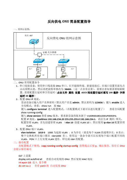
反向供电ONU简易配置指导一、组网示意图:二、ONU常用配置命令1、串口连接设备:使用串口线连接ONU串口,打开超级终端。
新建连接后,在端口设置里面先点击还原默认值,然后再把波特率修改为38400。
(这一点非常总要)。
需要注意如果需要粘贴配置,需要配置行延时和字符延时(点击文件属性设置ASCII码设置行延时填写100毫秒字符延时20毫秒)2、配置ONU IP地址:登录设备后输入用户名和密码(默认用户名是admin,默认密码为123456);键入enable进入全局模式;查看:show run 按tba键入configure terminal进入配置模式;(在配置模式下就可以进行配置了)查看全局配置show running-config键入show version查看ONU版本,要求新设备的版本新于V100R001B01D001P005SP4;配置IP地址:ipaddress 192.168.234.20 255.255.255.0 192.168.234.1,语法为IP 掩码网关;配置管理VLAN:首先创建管理VLAN (vlan 10创建VLAN 10),然后使用ip vlan 10配置管理VLAN。
3、配置ONU端口VLAN:vlan-isolation 1819 01000为起始VLAN ,0为步长(就是每个VLAN的递增步长,0表示,整个交换机所有端口都在vlan1000里),使用这一条命令就可以实现每个端口配置不同的VLAN,PON口上行实现VLAN透传。
即完成vlan的配置。
三、保存配置在配置模式下使用:copy running-config startup-config获得提示后按y,确认保存,保存后ONU 会提示保存成功OLT上设置display ont autofind all 查看自动发现的ONU 然后复制MAC地址int epon 0/8 进入某个槽dis ont au 2 查看pon3的自动发现ONUdisp ont info 4 all 查看1端口ONU 数量及状态ont add 2 4 mac-auth 000A-5A12-7648 snmp ont-linepro file-id 516 desc EN-2000-16 添加ONU quit添加虚端口service-port vlan 1819 epon 0/8/2 ont 4 multi-service user-vlan 1819指定加虚端口号的模板MA5680T(config-if-epon-0/4)#display ont info 1 all 查看1端口下信息MA5680T(config)#display service-port port 0/8/2 ont 4 sort-by port 查看4槽1端口第一个ont信息删除onuMA6680T(config)#undo service-port 733 删除6槽第一个ont虚端口16MA6680T(config)#interface epon 0/8 进入0筐6槽MA6680T(config-if-epon-0/6)#ont delete 2 4 删除3端口第一个ONUMA6680T(config-if-epon-0/6)#display ont info 3 all 查看3端口下信息display service-port epon 0/6/3 ont 21 查看1槽第8个ont信息四、ONU常用查看命令1、查看配置:show running-config2、查看端口:show interface ethernet 0/23、查看VLAN:show vlan 1004、查看端口POE属性:show poe mode interface 如果端口POE属性为enable,则在次端口必须接上供电器,用户才能够上网五、其它常用配置命令VLAN中添加端口:switchport ethernet 0/1;删除VLAN:no vlan 100(VLAN号或者all删除所有VLAN);恢复默认值:clear startup-config(在全局模式下执行,重启后恢复默认值,需要注意IP地址只能修改而不能够回复到默认值);重启设备:reboot;改变端口的PVID:首先进入到第四端口switchport ethernet 0/4,改变第四端口的PVID为1003switchport access vlan 1003需要注意1003 VLAN必须首先建立;返回上一级:exit;改变端口的POE属性:在端口模式下poe mode disable(关闭端口的POE认证属性,用户可以不供电直接接上端口使用,打开为poe mode enable);改变端口为TAG属性:在端口模式下tag_mode tag(或者untag);升级ONU:load application tftp 192.168.2.200 XXX.zblob 需要打开TFTP服务器,IP地址为TFTP 服务器IP地址,文件名需要包括扩展名。
格林韦迪-开通配置命令
格林韦迪-开通配置命令帮助命令:?, list, <tab>\\02-EPON开通文档\\《01-EPON快速开通指导.doc》1. 建立管理vlan,配置管理IP地址.interface vlan manage 100add port 1/1 taggedip address 192.168.2.100/24exitshow int vlan manage2. 配置默认网关ip route 0.0.0.0/0 192.168.2.254show ip route3. 配置SNMP命令service snmp enableservice snmp trap enableconfig snmp trapreceiver add 10.5.4.118 version v2c community publicconfig snmp community readonly gwbnqdshow running-config snmp4. 打开串口登录认证功能config login-authentication enable5. 添加用户账号,修改默认密码user add命令。
login-password,enable-password命令6. 修改命令行提示字符config hostname <hostname>7. 配置超长帧支持jumbo receive length 16008. 配置环路检测功能loop-detection enableloop-detection control enableshow loop-detectionshow loop-detection configshow alarm log {today/yestoday/device/onu}9. 配置OLT上的业务VLANinterface vlan v200 200add port 1/1 taggedadd port 5/1 tagged :需要在ONU上配置相同的VLAN(或 add port 5/1 untagged ) :不需要在ONU配置VLAN,使用默认VLAN 1exitshow interface vlan10. 配置ONU上的vlan(如需要)onu 5/1/1vlan dot1q_add 100vlan dot1q_port_add 100 1 2exitvlan dot1q_show11. 配置vlan 端口隔离功能onu 5/1/1vlan port_isolate 1vlan port_isolateexit12. 修改onu上的最大mac地址数限制数onu 5/1/1onu max-mac 2000exit13. 修改ONU上行默认带宽pon 5/1bandwidth class 2 .... 命令14. ONU第一次注册后,修改device name属性,保存ONU配置。
TiNet S2008M-S软件配置手册
TiNet S2008M-S 快速以太网交换机用户手册软件配置手册1.访问交换机2.端口配置3. VLAN配置4.组播协议配置5. QOS配置6. STP配置7.交换机管理和维护目录第1章访问交换机.................................................................................... 1-11.1 命令行接口 .................................................................................... 1-11.1.1 命令行接口配置任务列表....................................................... 1-11.1.2 命令行模式........................................................................... 1-21.1.3 理解命令语法........................................................................ 1-41.1.4 语法帮助 .............................................................................. 1-51.1.5 历史命令 .............................................................................. 1-71.1.6 命令中的符号........................................................................ 1-81.1.7 命令参数类型........................................................................ 1-81.2 用户管理........................................................................................ 1-91.2.1 系统缺省用户帐号................................................................. 1-91.2.2 增加用户帐号...................................................................... 1-101.2.3 修改密码 ............................................................................ 1-101.2.4 修改权限 ............................................................................ 1-111.2.5 删除用户帐号...................................................................... 1-111.2.6 查看系统用户信息............................................................... 1-121.3 管理交换机的途径 ........................................................................ 1-121.3.1 通过超级终端管理交换机..................................................... 1-121.3.2 通过telnet管理交换机......................................................... 1-14第2章端口配置........................................................................................ 2-12.1 端口简介........................................................................................ 2-12.2 端口配置........................................................................................ 2-12.2.1 端口的相关配置 .................................................................... 2-12.2.2 进入端口配置模式................................................................. 2-22.2.3 打开或关闭指定端口.............................................................. 2-22.2.4 配置端口双工模式和速度....................................................... 2-32.2.5 配置端口优先级 .................................................................... 2-32.2.6 开启或关闭端口的VLAN收包过滤功能................................... 2-42.2.7 开启或关闭端口的流量控制功能............................................. 2-42.2.8 配置端口描述........................................................................ 2-52.2.9 配置端口类型........................................................................ 2-52.2.10 配置trunk端口的allowed vlan ............................................. 2-62.2.11 设置trunk端口缺省VLAN ID ............................................... 2-62.2.12 将access端口加入到指定VLAN中 ..................................... 2-72.2.13 显示端口信息...................................................................... 2-72.2.14 显示端口统计信息 ............................................................... 2-82.2.15 清除端口统计信息 ............................................................... 2-82.3 端口镜像........................................................................................ 2-92.3.1 端口镜像简介........................................................................ 2-92.3.2 端口镜像配置........................................................................ 2-92.4 端口汇聚配置............................................................................... 2-112.4.1 端口汇聚简介...................................................................... 2-112.4.2 端口汇聚配置...................................................................... 2-112.5 端口CAR配置............................................................................. 2-122.5.1 端口CAR简介.................................................................... 2-122.5.2 端口CAR配置任务列表 ...................................................... 2-122.5.3 全局开启/关闭端口CAR ...................................................... 2-132.5.4 端口开启/关闭端口CAR ...................................................... 2-132.5.5 配置端口CAR重新打开端口的时间...................................... 2-142.5.6 配置端口CAR值 ................................................................ 2-142.5.7 显示端口CAR信息............................................................. 2-14第3章 VLAN配置....................................................................................... 3-13.1 VLAN简介...................................................................................... 3-13.2 VLAN端口类型............................................................................... 3-13.3 缺省VLAN(Default VLAN).......................................................... 3-23.4 VLAN配置...................................................................................... 3-23.4.1 VLAN配置任务列表............................................................... 3-23.4.2 创建/删除VLAN .................................................................... 3-33.4.3 增加/删除VLAN端口 ............................................................ 3-33.4.4 指定/删除VLAN描述字符...................................................... 3-43.4.5 设置端口类型........................................................................ 3-53.4.6 端口缺省VLAN ID设置......................................................... 3-53.4.7 tag VLAN设置....................................................................... 3-63.4.8 显示VLAN信息.................................................................... 3-63.5 GVRP配置..................................................................................... 3-73.5.1 GVRP协议简介..................................................................... 3-73.5.2 GVRP配置任务列表.............................................................. 3-73.5.3 全局开启/关闭GVRP............................................................. 3-73.5.4 端口开启/关闭GVRP............................................................. 3-83.5.5 显示GVRP状态 ................................................................... 3-83.5.6 GVRP配置举例..................................................................... 3-9第4章组播配置........................................................................................ 4-14.1 GMRP协议简介.............................................................................. 4-14.2 GMRP配置 .................................................................................... 4-14.2.1 GMRP配置任务列表.............................................................. 4-14.2.2 全局开启/关闭GMRP ............................................................ 4-14.2.3 端口开启/关闭GMRP ............................................................ 4-24.2.4 显示GMRP状态................................................................... 4-24.3 IGMP Snooping配置....................................................................... 4-34.3.1 IGMP Snooping协议简介....................................................... 4-34.3.2 IGMP Snooping配置.............................................................. 4-44.4 静态组播配置................................................................................. 4-44.4.1 静态组播简介........................................................................ 4-44.4.2 静态组播配置........................................................................ 4-5第5章QOS配置...................................................................................... 5-15.1 QOS简介....................................................................................... 5-15.2 QOS配置....................................................................................... 5-35.2.1 QoS配置任务列表................................................................. 5-35.2.2 流分类配置........................................................................... 5-35.2.3 队列调度配置........................................................................ 5-3第6章STP配置....................................................................................... 6-16.1 STP协议简介................................................................................. 6-16.2 STP配置........................................................................................ 6-16.2.1 STP配置任务列表................................................................. 6-16.2.2 开启/关闭交换机STP ............................................................ 6-26.2.3 开启/关闭端口STP................................................................ 6-26.2.4 配置交换机STP优先级......................................................... 6-36.2.5 配置交换机Forward Delay..................................................... 6-36.2.6 配置交换机Hello Time........................................................... 6-46.2.7 配置交换机Max Age ............................................................. 6-46.2.8 配置特定端口的Path Cost ..................................................... 6-56.2.9 配置特定端口STP的优先级 .................................................. 6-66.2.10 STP监控和维护................................................................... 6-6第7章交换机管理和维护.......................................................................... 7-17.1 配置文件管理................................................................................. 7-17.1.1 编辑配置文件........................................................................ 7-17.1.2 修改和保存当前配置.............................................................. 7-17.1.3 擦除配置 .............................................................................. 7-17.1.4 执行已保存的配置................................................................. 7-27.1.5 显示已保存的配置................................................................. 7-27.1.6 显示当前配置........................................................................ 7-27.1.7 配置文件执行模式的切换....................................................... 7-37.2 在线加载升级程序 .......................................................................... 7-37.2.1 通过TFTP上、下载文件....................................................... 7-47.2.2 通过FTP上、下载文件......................................................... 7-57.2.3 通过Xmodem下载文件......................................................... 7-6 7.3 设备管理........................................................................................ 7-67.3.1 MAC地址表管理.................................................................... 7-67.3.2 重启交换机......................................................................... 7-10 7.4 系统维护...................................................................................... 7-107.4.1 show命令查看系统状态和系统信息....................................... 7-107.4.2 系统基本配置及管理............................................................ 7-127.4.3 网络连接的测试命令............................................................ 7-127.4.4 回环测试命令...................................................................... 7-137.4.5 在线用户管理...................................................................... 7-14 7.5 利用SNMP对交换机监控............................................................. 7-147.5.1 SNMP协议介绍................................................................... 7-147.5.2 SNMP配置 ......................................................................... 7-15 7.6 系统IP配置................................................................................. 7-207.6.1 管理VLAN配置.................................................................. 7-207.6.2 手工方式配置交换机IP地址 ................................................ 7-207.6.3 BOOTP ............................................................................... 7-217.6.4 DHCP ................................................................................. 7-217.6.5 IP地址配置举例................................................................... 7-217.6.6 显示交换机IP地址.............................................................. 7-22第1章访问交换机这章主要内容是管理TiNet S2008M-S快速以太网交换机所需要的一些基本知识。
格林耐特S2008B基本配置
格林耐特S2008B基本配置一、网络地址、VLAN规划规划好某小区的地址表格。
一般网络中心将事先提供该小区的表格,如下图所示:注:该小区的点播业务Vlan为858,该小区的楼道交换管理Vlan为41,交换机管理IP为10.51.1.*。
点播业务Vlan和设备管理Vlan及地址由网络中心统一规划并提供给各乡镇。
二、连接交换机用一台笔记本或普通PC,拿一根普通的网线接到交换机的任一端口(推荐使用8号口)。
1、设置计算的IP地址,在桌面的网上邻居上右击,在弹出的菜单中选择属性,如下图所示:2、在弹出的界面中,在本地连接上再右击,选择属性,如下图所示:3、在中间的框框中找到,Internet协议(TCP/IP),选中后,点击下面的属性,如下图所示:4、选择使用下面的IP地址,在IP地址栏里输入:192.168.2.200(因为交换机出厂的默认地址是:192.168.2.1),为方便登录更改过后的IP地址,还要再设一个地址,点击下面的高级,如下图所示:5、点击添加,如下图所示:6、添加一个小区的交换机管理地址,如我们这个例子里的飞虹新村就是10.51.1.*的地址,我们设成10.51.1.200,填写完成后,点击“添加”,所有的窗口都点“确定”,完成计算IP 的设置。
三、配置交换机1、打开浏览器,在地址栏里输入:192.168.2.1,回车,如下图所示:2、在出现的登录界面中输入用户名和密码,默认是:admin,123456,输好后点击“OK”.3、对于一般基本的配置我们只用到“交换机管理”和“VLAN设置”这两项,点击可展开子菜单,如下图所示:4、在“交换机管理”展开的子菜单中,我们一般常用前面三个,如下图所示:5、点击“口令设置”,可以修改登录该交换机的用户名和密码,改好后点击“Update”。
6、点击“系统IP设置”,可以修改该交换机的IP地址,注意掩码和网关要设置正确。
7、点击“系统状态”可以查看交换机的MAC地址,软件版本,按要求把该交换机的MAC地址填入EXCEL表格。
Eaton 16RES08T产品说明书

Eaton 16RES08TEaton molded case circuit breaker accessory rating plug, Rating Plug, 800 A, Frame RG, Series GGeneral specificationsEaton molded case circuit breaker accessory rating plug16RES08T 7866795813085 in1.6 in1.7 in 0.08 lb Eaton Selling Policy 25-000, one (1) year from the date of installation of the Product or eighteen (18) months from the date of shipment of the Product, whichever occurs first.Contact Manufacturer Product NameCatalog Number UPCProduct Length/Depth Product Height Product Width Product Weight WarrantyCompliancesFrame RG Series G Rating Plug 800 A Application of Tap Rules to Molded Case Breaker Terminals Application of Multi-Wire Terminals for Molded Case Circuit BreakersMulti-wire lugs product aidCircuit breaker motor operators product aidSeries G MCCB quick selectorPower metering and monitoring with Modbus RTU product aidPlug-in adapters for molded case circuit breakers product aidMotor protection circuit breakers product aidMolded case circuit breakers providing higher levels of selective coordination product aidCurrent limiting molded case circuit breaker module for series G, JG and CLComprehensive circuit protection for control panel applicationsCurrent limiting molded case circuit breaker module product aidHigh performance operating handles for Series G circuit breakers product aidStrandAble terminals product aidBreaker service centersMolded case circuit breakers catalogEaton's Volume 4—Circuit ProtectionFlex shaft handle installation tutorialEaton Specification Sheet - 16RES08TNG and ND-Frame molded case circuit breakersMOEM MCCB product selection guideSelling Policy 25-000 - Distribution and Control Products and ServicesFrame size SeriesTypeAmperage Rating Application notesBrochuresCatalogsMultimediaSpecifications and datasheets Warranty guidesEaton Corporation plc Eaton House30 Pembroke Road Dublin 4, Ireland © 2023 Eaton. All Rights Reserved. Eaton is a registered trademark.All other trademarks areproperty of their respectiveowners./socialmedia。
Emesser ATE208 小型“双箭头”双筒声音质量的双筒微机说明书
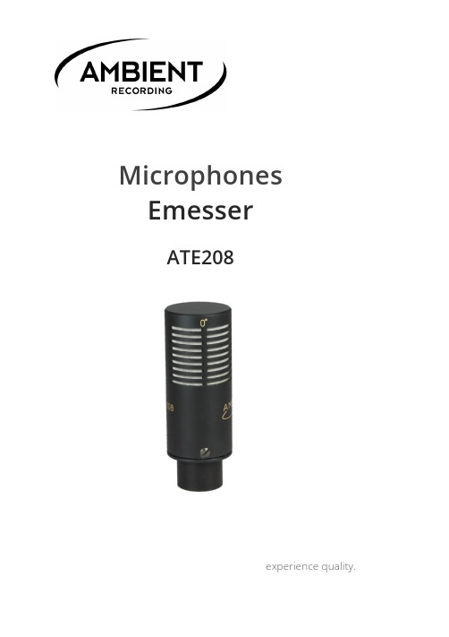
Microphones EmesserATE208experience quality.experience quality. ATE208CONTENT PAGEFIGURE-OF-EIGHT 2 PURCHASED PARTS PACKAGE 4 TECHNICAL SPECIFICATION 5 WARRANTY 8© 2016, Ambient Recording GmbH 1ATE208www.ambient.de/en2FIGURE-OF-EIGHTThe Emesser (ATE 208) is very small “figure-of-eight” microphone intended to convert any boom mike on the fly into a M/S stereo system.Example for useFeaturing a high quality real condenser powered on 48V phantom, it delivers an enhanced dynamic range required for critical recordings.It comes complete with mounting clip and Y-loom, which outputs both M and S signals in a standardbalanced 5-Pin-XLR.experience quality. ATE208Including all the necessary accessories and allowing continued use of the existing shotgun mike, suspension and wind shield it offers a very economic solution for those who don‘t want to part with their favored shotgun to go stereo.Due to the M/S technology and the same mike being used for dialogue and ambience recordings seamless transitions between mono and stereo are feasible without alteration of the sound characteristics.The frequency response therefore was custom-tailored to match the acoustic pattern of typical boom mikes at 90° with the characteristic distinct bass roll-off.The result is a distinguished stereo perception with pronounced presence and minimal negative phase correlation at the low end with exceptional good suppression of handling noise.© 2016, Ambient Recording GmbH 3ATE208www.ambient.de/en4PURCHASED PARTS PACKAGEATE208 Emesser ATE-Box Pouch bagB5 Schoeps wind shield ATEC-R Rycote clip ATEKStereo cablingexperience quality. ATE208TECHNICAL SPECIFICATIONPolar pattern Bidirectional/…figure of eight“ Frequency response +/- 3 dB 200 –16.000 Hz Sensitivity 12 mV/Pa Signal to noise ratio CCIR 66 dBSignal to noise ratio DIN/IEC 79 dB - A Equivalent SPL rated at CCIR 28 dB Equivalent SPL rated at DIN/IEC 15 dB - A Max. SPL 132 dB SPL Dimensions (L|D) 53mm|Ø 19mm Weight 40grs. Powering 48 V phantompowerMating connector TA3FWiring Pin 1 = groundPin 2 = audio(+)Pin 3 = audio(-) © 2016, Ambient Recording GmbH 5ATE208www.ambient.de/en6experience quality.ATE208© 2016, Ambient Recording GmbH7ATE208www.ambient.de/en8WARRANTYAmbient Recording GmbH warrants the ATE 208 EMESSER against defects in materials andworkmanship for a period of ONE (1) year from date of original retail purchase. This is a non-transferable warranty that extends only to the original purchaser. Ambient Recording GmbH will repair or replace the product at its discretion at no charge. Warranty claims due to severe service conditions will be addressed on an individual basis. THE WARRANTY AND REMEDIES SET FORTH ABOVE ARE EXCLUSIVE. AMBIENT RECORDING GMBH DISCLAIMS ALL OTHER WARRANTIES, EXPRESS OR IMPLIED, INCLUDING WARRANTIES OF MERCHANTABILITY AND FITNESS FOR A PARTICULAR PURPOSE. AMBIENT RECORDING GMBH IS NOT RESPONSIBLE FOR SPECIAL, INCIDENTAL, OR CONSEQUENTIAL DAMAGES ARISING FROM ANY BREACH OF WARRANTY OR UNDER ANY OTHER LEGAL THEORY. Because some jurisdictions do not permit the exclusion orlimitations set forth above, they may not apply in all cases.experience quality. ATE208For all service, including warranty repair, please send the ATE 208 EMESSER, along with proof of purchase date to your retailer, or, if not applicable, to:Ambient Recording GmbHSchleissheimer Str. 181 CDE – 80797 Muenchen, Germany Please obtain a return authorization through the contact form on our website before sending in a unit.© 2016, Ambient Recording GmbH 9experience quality.MADE IN GERMANYAmbient Recording GmbHSchleissheimer Straße 181 C | DE – 80797 Münchenvox +49 89 360 55 10-0 | fax +49 89 651 85 58www.ambient.de|***************© 2016, Ambient Recording GmbH。
新格林耐特8口交换机精简配置说明.
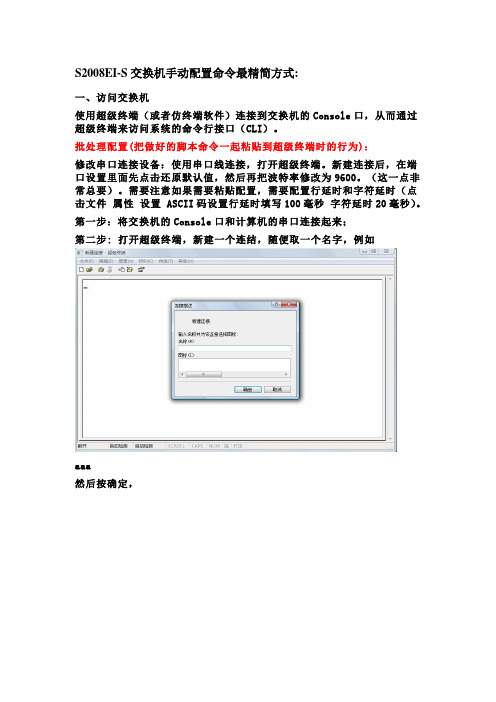
S2008EI-S交换机手动配置命令最精简方式:一、访问交换机使用超级终端(或者仿终端软件)连接到交换机的Console口,从而通过超级终端来访问系统的命令行接口(CLI)。
批处理配置(把做好的脚本命令一起粘贴到超级终端时的行为):修改串口连接设备:使用串口线连接,打开超级终端。
新建连接后,在端口设置里面先点击还原默认值,然后再把波特率修改为9600。
(这一点非常总要)。
需要注意如果需要粘贴配置,需要配置行延时和字符延时(点击文件属性设置 ASCII码设置行延时填写100毫秒字符延时20毫秒)。
第一步:将交换机的Console口和计算机的串口连接起来;第二步: 打开超级终端,新建一个连结,随便取一个名字,例如aaa然后按确定,然后选择COM口,按确定,端口设置选择为还原为默认值,再确定第二步:此时就可以以看到登录提示信息:Username(1-32 chars):第三步:输入正确的用户名,按回车,在提示下再输入相应密码。
如果是首次登录交换机,就应该使用缺省的用户名admin登录,此时输入登录密码123456,以系统管理员的身份进行操作。
第四步:成功登录交换机后,系统显示如下信息:TiNet>第五步:输入enable回车,系统显示如下信息:TiNet# 说明:特权模式第六步:输入configure terminal回车,系统显示如下信息:TiNet(config)# 说明:配置模式,请在此模式下进行配置TiNet(config)#ipaddress 172.20.100.10 255.255.255.0 172.20.100.1 说明:配置交换机IP地址这样通过IP地址,我们可能在WEB页面配置交换机了,但我们不建议在配置开始就用IP地址去配置,出于安全、稳定性的考虑,交换机的WEB页面并没把全部命令都加进去,还有不少的配置与调试信息都在命令行里。
另外,为了安全考虑,本地交换机的各端口默认VLAN 都不在管理VLAN里,这样,直接用网线接交换机会无法访问。
ESB08-16SL用户手册

Quick Start Guide PROFINET switch 4 8 16 port说明书

Quick Start Guide PROFINET switch 4/8/16 portContents1. Safety instructions 32. Introduction 43. Preparing the PROFINET switch 54. Planning of the GSDML files 65. Setting the port properties 76. Topology detection 77. Assign the PROFINET switch a name 88. Media Redundancy Protocol (MRP) 99. Diagnosis and configuration via the web interface 1010. Switch diagnosis and settings 1211. Port mirroring 1212. Statistics 1313. Agents 1414. SNMP 1515. Setting the time 1616. Resetting to factory settings 1717. Firmware update 1718. LED status information 1819. Button functions 1820. Technical data 191. Safety instructionsTarget audienceThis description is only intended for trained personnel qualified in control and automation engineering who are familiar with the applicable national standards.For installation, commissioning, and operation of the components, compliance with the instruc-tions and explanations in this operating manual is essential. The specialist personnel is to ensure that the application or the use of the products described fulfills all safety requirements, including all applicable laws, regulations, provisions, and standards.Intended useThe device has a protection rating of IP 20 (open type) and must be installed in an electrical operating room or a control box/cabinet in order to protect it against environmental influences. To prevent unauthorized operation, the doors of control boxes/cabinets must be closed and possibly locked during operation.The consequences of improper use may include personal injury to the user or third parties, as well as property damage to the control system, the product, or the environment. Use the device only as intended!OperationSuccessful and safe operation of the device requires proper transport, storage, setup, assembly, installation, commissioning, operation, and maintenance.Operate the device only in flawless condition. The permissible operating conditions and performance limits (technical data) must be adhered to.Retrofits, changes, or modifications to the device are strictly forbidden.2. IntroductionThis Quick Start Guide explains the basic settings for the initial commissioning of PROFINET switches for use in a PROFINET project.You can find further information in the manual. You can find this under /activenetworkcomponents or scan the QR code directly.P1 — P4:For PROFINET devices or otherEthernet devicesVoltage supplyOperation LEDs (see page 18)FCN:Function button RST:Reset buttonVoltage supplyOperation LEDs (see page 18)P1 — P16:For PROFINET devices or otherEthernet devices Voltage supplyOperation LEDs (see page 18)FCN:Function button RST:Reset buttonFCN:Function buttonRST:Reset buttonSCAN QR CODETO GET MANUALP1 — P8:For PROFINET devices or other Ethernet devices3. Preparing the PROFINET switch3.1 ConnectionThe PROFINET switch must be supplied with 24 V DC at the wide range input 18 – 30 V DC via the provided connector plug.The RJ45 sockets “P1 – P4” (4 port switch), “P1 – P8” (8 port switch) and “P1 – P16” (16 port switch) serve the connection of the network participants(PROFINET or Ethernet).SCAN QR CODETO GET GSDML3.2 Install GSDML filePlease download t he GSDML file under /activenetworkcomponents or scan the QR code.Note: The housing of the PROFINET switch is not grounded. Please connect the functional grounding connection (FG) of the PROFINET switch correctly with the reference potential.4. Planning of the GSDML filesFollowing installation, the PROFINET switch can be found in the hardware catalog under “Other field devices g PROFINET IO g Network Components g LAPP GmbH g LAPP PN switch”. Add the “PROFINET Switch, 4 port”, “PROFINET Switch 8 port” of “PROFINET Switch, 16 port” device to the project and connect it with your PROFINET network.By calling up the object properties, you must assign the PROFINET switch a unique PROFINETname and check the IP address for plausibility in the project.Important: The real device must later be assigned the same name as in the project.See also Chapter 6.5. Setting the port propertiesEach port of the PROFINET switch can be individually configured.Transfer medium/duplex:“Activate”The port can be switched off here. This option is recommended when the port shouldn’t be used. Unauthorized trespass into the network is prevented.Transmission rate “Automatic”The port synchronizes itself automatically with the communication partner (auto-negotiation).“TP 100 Mbps”,Transmission rate full duplex Fixed specification of the transmission rate. This option is recommended when connecting PROFINET IO devices.MonitorSend a diagnosis by Link DownEnable autonegotiationAutomatic recognition of the transmission speed and the cable type (cross or patch cable)6. Topology detectionThe PROFINET switch supports the mechanisms for neighborhood detection (LLDP). With this function it is possible to detect the topology of a PROFINET network, or to specify it for purposes of checking for the correct structuring by the configuration.If the topology was prescribed in the configuration, neighboring devices can also be assigned the PROFINET name in the event of the replacement of a device.This makes the recognition and testing of the network topology and the “device exchange in operation” of connected PROFINET participants possible.7. Assign the PROFINET switch a nameWhen the configuration of the PROFINET switch has been completed in the hardware configurator of the engineering tool, it can be loaded into the PLC.In order that the PROFINET switch can be found by the PROFINET controller, the PROFINET device name must be assigned to the PROFINET switch. To this purpose, use the function “Assign device name”, which you can access in the Online menu with the right mouse button when the PROFINET switch is activated.With the “Update list” button, the network can be browsed for PROFINET participants. The PROFINET device name can be assigned to the device with “Assign name”.The clear identification of the PROFINET switch is ensured here by the MAC address of the device. The MAC address of the device can be found on the device front of the PROFINET switch.The IPSet tool, which can be downloaded at no charge from the LAPP website, can also be used to set the PROFINET name.If the DP/PN Coupler has been assigned the correct name, it is recognized by the PLC and configured. If configuration has taken place correctly, the PROFINET “BF” LED should be off. If configuration has also taken place correctly on the PROFIBUS side, the PROFIBUS “BF” LED should also be off. When both network sides have been configured appropriately (number and size of the IO areas agree), the “SF” LEDs on both sides should also be out on both sides and data transmission be underway.SCANQR CODETO GETIPSET8. Media Redundancy Protocol (MRP)The PROFINET switch supports the optional media redundancy protocol (MRP) as MRP client. MRP enables ring wiring, which also makes operation of the PROFINET network possible in the event of the failure of a cable or of a participant.There must be at least one MRP master (e.g. the CPU) in an MRP ring. All other participants of the ring are then MRP clients.In order to assign the PROFINET switch to an MRP ring, the “Client” media redundancy role must be set for the “Media redundancy” option under “Properties/General”.Important: If ring wiring is produced without the MRP roles being configured for all devices involved, this can result in functional disruptions of the PROFINET network!9. Diagnosis and configuration via the web interfaceThe web interface is also accessible under the IP address assigned to the PROFINET switch in the PROFINET network.When the web interface is first called up, the password of the “admin” user is the serial number of the device. The serial number is indicated on the right housing side part (e.g. “50001234”). It is absolutely necessary to assign a new password following the first login:One goes to the system view following entry of the new password:Note: If the PROFINET switch is configured and used in a PROFINET network, settings in the web interface are only to be viewed as a diagnosis.A reconfiguration of PROFINET-related settings (Port Status, LLDP, DCP, Ring Redundancy) is then not possible in the web interface.11. Port mirroringIn order to be able to carry out frame analyses or recordings, Port Mirroring can be activated in the PROFINET switch. With Port Mirroring, the frame transfer from one “mirrored port” to the “Monitor Port” is completely mirrored, on which an analysis PC can then record everything.10. Switch diagnosis and settingsExtensive information and settings for the function of the switch are accessible in the Switch menu.12. StatisticsDetailed statistics on the data transfer can be queried in the “Statistics” menu.Among other things, the quality of the transmission can be monitored in the sub-menu “Statistics by Error”.In order to already be able to view basic information about the switch at the start website, before or without having logged in, the option “System Status Without Login” can be selected. With “Web Session Timeout”, it can be established whether an automatic logout should take place in the event of inactivity at the website for security reasons.The PROFINET switch supports SNMP (“Simple Network Management Protocol”) in order to also enable the identification and diagnosis of the switch for IT administration tools.15. Setting the timeThe PROFINET switch contains a system clock for the issuing of logs and alarm messages. This can be set either manually or automatically by an SNTP server.16. Resetting to factory settingsIn order to reset the PROFINET switch to the delivery status, the function “Factory Reset” can be used in the web interface under “System” g “Restart”.Alternatively, the PROFINET switch can be reset by pressing and holding the “FCN” button while the device restarts. A restart can be carried out by switching the power supply off and on or by activating the RST button.The successful resetting of the parameters and settings is acknowledged during the boot process by the SF LED lighting up together with the PWR LED.17. Firmware updateA firmware update can be carried out via the web interface.The firmware update file can be selected in the menu “System g Firmware”. The file has the ending “HUF”.The firmware is transferred to the PROFINET switch and burned with the “Send” button.The new firmware is active following a restart of the PROFINET switch.Important: Switching off the power supply during the update process can make the device unusable.SCAN QR CODETO GETFIRMWAREPlease download t he firmware update file under /activenetworkcomponents or scan the QR code.18. LED status informationPWROff No power supply or device defectiveOn Device is correctly supplied with voltageRUNFlashing light The device startsOn The device is ready to operateBFOn The device has no configuration and/or there is noconnection with the PROFINET controllerSFOn A PROFINET diagnosis is availableRJ45 LEDsGreen (Link)ConnectedOrange (Act)Data transfer at the networkNote: The LEDs “RUN”, “BF”, and “SF” all flash synchronously when the PROFINET function for device identification has been activated.19. Button functionsFCN The PROFINET switch can be reset to factory settings with the“FCN” button.If the “FCN” button is pressed during the run-up time of theswitch, the orange “SF” LED begins to flash. The blinkingindicates that the switch will be immediately reset to factorysettings and restarted as soon as the switch is released.The run-up phase is indicated by the blinking of the “RUN”LED.RST The “RST” button triggers an immediate restart ofthe PROFINET switch, in the course of which all saved settingsare retained.20. Technical dataPROFINET switch, 4 port, managed ETHERLINE® ACCESS PNF04T PROFINET switch, 8 port, managedETHERLINE® ACCESS PNF08TPROFINET switch, 16 port, managedETHERLINE® ACCESS PNF16TDimensions (D x W x H)32 x 59 x 76mm32 x 82 x 76mm32 x 146 x 76mmWeight Approx. 130g Approx. 180g Approx. 310gPROFINET ports-Protocol PROFINET IO as defined in IEC 61158-6-10PROFINET IO as defined in IEC 61158-6-10PROFINET IO as defined in IEC 61158-6-10 -Physical layer Ethernet Ethernet Ethernet-Transmission rate100 Mbps, full duplex100 Mbps, full duplex100 Mbps, full duplex-Connection 4 x RJ45, integrated switch8 x RJ45, integrated switch16 x RJ45, integrated switch-Features Media Redundancy Protocol (MRP)Automatic addressing/Topology recognition (LLDP, DCP)Media Redundancy Protocol (MRP)Automatic addressing/Topology recognition (LLDP, DCP)Media Redundancy Protocol (MRP)Automatic addressing/Topology recognition (LLDP, DCP)Status indicator 4 LEDs function status,8 LEDs Ethernet status 4 LEDs function status,16 LEDs Ethernet status4 LEDs function status,32 LEDs Ethernet statusVoltage supply DC 24 V (18 ... 30 V DC)DC 24 V (18 ... 30 V DC)DC 24 V (18 ... 30 V DC) Current draw Max. 250 mA at 24 V DC Max. 350 mA at 24 V DC Max. 290 mA at 24 V DC Power dissipation Max. 2.4 W Max. 2 W Max. 5.5 WPermissible ambient temperature-40°C … +75°C-40°C … +75°C0°C ... +60°CTransport and storage temperature-40°C … +85°C-40°C … +85°C-40°C ... +85°C Protection rating IP 20IP 20IP 20Certifications CE, UL CE, UL CE, ULUL UL 61010-1/ UL 61010-2-201UL 61010-1/ UL 61010-2-201UL 61010-1/ UL 61010-2-201-Voltage supply24 V DC (18 ... 30 V DC, SELV and limited energycircuit)24 V DC (18 ... 30 V DC, SELV and limited energycircuit)24 V DC (18 ... 30 V DC, SELV and limited energycircuit)-Pollution degree222-Altitude Up to 2,000 m Up to 2,000 m Up to 2,000 m -Temperature cable rating87°C87°C87°CNote:The contents of this Quick Start Guide have been checked by us so as to ensure that they match the hardware and software described.However, we assume no liability for any existing differences, as these cannot be fully ruled out.The information in this Quick Start Guide is, however, updated on a regular basis. When using your purchased products, please make sure to use the latest version of this Quick Start Guide, which can be viewed and downloaded on the Internet from /activenetworkcomponents.Our products contain open source software, among others. This software is subject to the respectively relevant license conditions. We can send you the corresponding license conditions, including a copy of the complete license text together with the product. They are also provided in our download area of the respective products under/activenetworkcomponents.We also offer to send you or any third party the complete corresponding source text of the respective open source software for an at-cost fee of 10.00 Euro as a DVD upon request.This offer is valid for a period of three years, starting from the date of product delivery.1) SIMATIC is a registered trademark of Siemens AG.Our customers are at the center of everything we do. We welcome all ideas and suggestions.。
TE Connectivity KISSLING Toggle Switch Series 08说明

KISSLINGTOGGLE SWITCHSeries 08 - from TE Connectivity (TE)Quality SwitchThe KISSLING toggle switches from TE Connectivity’s product fami-ly have been developed under strict guidelines to meet international standards.This series of toggle switches is mainly used as robust, industrial and durable switches in military vehicles. The housing of the Series 08 is made of duroplastic and meets IP68/IP6K8 protection class standards. This toggle switch is equipped with a safe switching mechanism, which is provided by an additional internal contact protection.All these switches are sealed themselves and we offer additional seal-ing rings for improved mounting solutions and optional bellows for the handles. Our broad selection of toggles includes many options for switching configuration, termination type, load carrying capabilities and locking combinations.TE Connectivity provides switches both with and without switch guards to prevent accidental switching, as well as individual switches and complete switch assemblies with additional sealed housings for simplified vehicle assembly procedures.Features• Military grade robustness VG 95 318• High quality silver alloy or gold plated contacts• Sealing technology meets IP68/IP6K8 • 2- and 3-Position switch actions • Variety of available switching styles • Locking options for individual needsApplications• Commercial vehicles• Aviation ground support equipment • Military ground equipment and vehicles • Plant and industrial engineering • Medical equipment•Construction machinerySpecificationTechnical Data Housing Material Duroplast GFConstruction iaw VG 95 318 and IEC 1 020SealConnectionIP68 IEC 60529 / IP6K8 DIN 40050 part 9 / IP6K8 ISO 20653IP00 IEC 60529 / IP00 DIN 40050 part 9 / IP00 ISO 20653Current carrying parts CuZn-alloyContact material Silver-alloy or gold plated contacts Temperature range-55˚C to +85˚C Electrical life (nominal load)100.000 cyclesNominal voltage / Continuous current 28VDC, 20A ohmic load28VDC, 15A L/R = 5msec inductive load 115VAC, 15A inductive load Min. switching capacity12VDC, 20mATechnical drawingsScrews M 3,5 x 6 - ISO 1580Soldering terminal to AWG 14FASTON DIN 46 244 - A 6,3 - 0,8for receptaclesConnectionKeyway side 1 Pole2 Pole4 PoleKeyway sideType with bellows for use in severe conditionsdepending on specific environmentalapplication:CR-Neoprene (933)FVMQ-Fluorsilicone (955)* valid for versions with lockingMounting Detail:with Locking RingMounting Detail:without Locking RingOrdering InformationSwitching StylesBridge / * These positions are only momentary. All others are maintained.TE Connectivity, TE, TE connectivity (logo), KISSLING (word) and FASTON are trademarks licensed or owned by the TE Connectivity family of companies. All other logos, products and/or company names referred to herein might be trademarks of their respective owners.The information given herein, including drawings, illustrations and schematics which are intended for illustration purposes only, is believed to be reliable. However, TE Connectivity makes no warranties as to its accuracy or completeness and disclaims any liability in connection with its use. TE Connectivity‘s obligations shall only be as set forth in TE Connectivity‘s Standard Terms and Conditions of Sale for this product and in no case will TE Connectivity be liable for any incidental, indirect or consequential damages arising out of the sale, resale, use or misuse of the product. Users of TE Connectivity products should make their own evaluation to determine the suitability of each such product for the specific application.© 2020 TE Connectivity | All Rights Reserved. K1166730 | Version 04/2021AccessoriesSwitch Guard:Receptacle:For quick connection, increase safety and prevents from contact the fasteners (IP20) Inverse-polarity protection.Available for switches with faston connection2- POLE(depth 41,5)1- POLE(depth 41,5)Locking optionsSeal ring: 08.0.0.50For sealing of mounting hole。
SMART THUMP ST16肩部电缆故障定位系统说明书

SMART THUMP ST16Portable Cable Fault Location System■■Delivers 1500 J at 8/16 kV■■16-kV DC high voltage proof test andinsulation resistance test■■Easy Go automatic test sequence toproof test, prelocate and pinpoint■■I nterprets test results for user■■5.7 in. transflective color display■■Safety / grounding check■■U SB interfaceDESCRIPTIONThe SMART THUMP ST16 Portable Cable Fault Locating System provides safe, efficient and extremely easy-to-use solutions for quickly identifying, prelocating and pinpointing various types of cable faults for power cables. The ST16 was developed to meet the requirements for typical low- and medium-voltage distribution cable fault location markets.Circuit parameters include:n System voltage up to 35 kVn■Insulation EPR or XLPEn■Typical conductor sizes between #2 and 500 MCM(34 mm2 to 250 mm2)n Typical circuit lengths from a few hundred feet (100 m) up to 3 miles (17,000 ft or 5,000 m)Typical end users include: operations department of power utility companies, electrical departments within municipalities including street light maintenance, private network operators, high voltage electrical contractors, service companies, port authorities, mining, airports, military bases, petrochemical and paper companies. The ST16 unit incorporates HDW’s “E-Tray” technology, a concept that has been already proven in other products (EZ-Thump, EZ-Restore Overdrive, and TDR T3090) and whichwill be carried forward into new Megger products in the future. The E-Tray adds the unique capability to access and operate every function through an innovative and intuitive user interface, without the need to make adjustments and the software suggesting the next logical step.APPLICATIONSThe SMART THUMP ST16 represents a new generation of advanced underground cable fault locating systems that require less training than a traditional thumper-only system. It is the only fault locator with built-in intelligence to interpret the results of the initial test sequence. The “turn & click” rotary button operation lets the user automatically proof test, pre-locate, and pinpoint the fault from one convenient control console. No adjustments are required. The unit automatically sets the thump voltage to minimize the stress applied to the cable. The ST16 features an automatic safety check to protect the user from incorrect or faulty ground connections (F-Ohm).The heavy-duty wheels of the unit are ideal for use in rough terrain. The ST16 is capable of being permanently installed in a vehicle (truck mount version).FEATURES AND BENEFITSThis fully inegrated system can be operated from either its internal battery/inverter, external 12 VDC or 120/230 VAC. Additional features are:■“Quick-Steps” is especially convenient where operators may not be called upon to use the equipment on a regular basis■“Expert Mode” provides up to 20 individual TDR features to the experienced user for optimum fault locating results■Custom configurable menus for the TDR function■DC testing up to 16 kV with indication of insulation resistance value■Rugged, powder coated IP54 designed enclosure■Safe Op check protects user from incorrect or faulty and ground connections (F-Ohm)■Easy Go operation eliminates lengthy training■Quick access to all components in case of serviceSMART FeaturesEntirely automatic test sequences includes proof test, prelocate, andpinpointAutomatic interpretation regarding type of fault (i.e. open, burnt in theclear, short)Automatic adjustment of thump voltage (uses selectable)Automatic alphanumeric display of cable and fault distanceUSB Host interface 2.0TDR trace export and system upgrades Mounting and Enclosure Mounted on heavy-duty wheels (14”)Rain tight powder coated enclosure IP54 (open)(Also available as vehicle-mount unit)Digital “Analog” Meter Displayed on LCD screenEnvironmentalOperating Temperature: -20C to +50C; -4F to +122F Storage Temperature: -25C to +65C; -13F to +149F IP RatingIP54 (with top open)Weight318 lbs (134 kg) includes wheels, battery and inverter & 50 ft of HV / Ground CableDimensions20 x 46 x 24 in. (500 x 1170 x 600 mm) W x H x DSPECIFICATIONSImpulse Generator (Thumper) Operating modes:Arc Reflection Method (ARM ®) 0-8/0-16 kVICE surge pulse (optional in North America), standardother countries 0-8/0-16 kV Direct surge (Thumping) 0-8/0-16 kV DC-HV proof test and resistance readout (Ω)Burning / Fault Conditioning 0-8/0-16 kV Sheath fault test & pinpointing /Secondary Fault Locating (optional) 0-5/10 kVTDR TDR mode and all prelocation functions (25,000 ft, optional 100,000 ft)Energy OutputDual stage: 1500 J @ 8 kV and 16 kV Proof test: 0 to 16 kV continuous Burn current: 60 mA maxKey FeaturesSingle-shot thump in ARMBuilt-in inductive type ARM filter 8 second thump cycle @ max output Automatic cable and system discharging Display FeaturesTransflective TFT color display, sunlight proof 5.7 in., 640 x 470 pixel resolutionPower Options120/230 V, 60/50 Hz ac operation12 V deep cycle marine battery with internal dc charger/inverter (standard)ISO STATEMENTRegistered to ISO 9001:2008 Cert. no. 110006.01ST16_DS_EN_Megger is a registered trademark .UKArchcliffe Road, Dover CT17 9EN EnglandT +44 (0) 1 304 502101 F +44 (0) 1 304 207342******************UNITED STATES 4271 Bronze WayDallas, TX 75237-1019 USA T 1 800 723 2861 (USA only)T +1 214 333 3201F +1 214 331 7399******************OTHER TECHNICAL SALES OFFICESValley Forge USA, College Station USA,Sydney AUSTRALIA, Täby SWEDEN,Ontario CANADA, Trappes FRANCE,Aargau SWITZERLAND, Dubai UAE, Mumbai INDIA, Johannesburg SOUTH AFRICA, and Chonburi THAILANDGERMANYMEGGER/SebaKMT D 96148 Baunach Dr.Herbert-Iann Str.6T +49-9544-680 F +49-9544-2273*****************。
Ernitec Electra Manual Electra S16F说明书

Professional Surveillance Solutions ElectrabyManualElectra S16FIntroductionPower-over-Ethernet (PoE) eliminates the need to run DC power to other devices on a single wired LAN. Using Power-Over-Ethernet, installers only need to run a single CAT 5cable that carries both data and power to each device. This allows greater flexibilliy in the location of the network devices. And in many cases significantly decreases the installation costs.There are two system components in PoE–the PSE (Power Sourcing Equipment) and the PD (Powered Device). The IEEE 802.3af/at specification defines PSE as a device that inserts power onto an Ethernet cable. The PSE may be located at the switch (Endspan configuration). Or it may be a separate device (Poe Injector) located between the switch and the PD (Midspan configuration). The PD is the natural termination of this link, receiving the power and the data And it could be an IP camera or an IP phone or a WLAN Access Point that require power.The current is transmitted over 2 of the 4 twisted pairs of wires in a Category-5, 6, 7 cable.Power-over-Ethernet follows the IEEE 802.3af/at specification and is completely compatiblewith existing Ethernet switches and networked devices. Because the Power Sourcing Equipment (PSE) tests whether a networked device is PoE-capable, power is never transmitted unless a Powered Device is at the other end of the cable. It also continues to monitor the channel. If the Powered Device does not draw a minimum current, because it has been unplugged or physically turned off, the PSE shuts down the power to that port.Optionally, the standard permits Powered Devices to signal th the PSEs exactly how much power they need.The PoE switch is a multi-port fast Ethernet switch that can be used to build high-performance switched workgroup networks. This switch is a store-and-forward device that offers low latency for high-speed networking. It also features a “store-and-forward” switching scheme that allows the switch to auto-learn and store source addresses in a 8K-entry MAC address table. The switch is targeted at workgroup, department or backbone computing environments.Hardware DescriptionThe Front Panel:The front panel constists of LED Indicationes, 16x 10/100/1000M RJ45 ports plus 4 x 1000M SFP portsFigure 2. Front panel view of LED indicationsFigure 2LED Status Color Description Power On Green The switch is supplied with suitable power LINK/ACT ON Green The port is connecting Blinks -The port is recieving or transmitting data Off -The port is not linked successfully with the device PoE On Green PD is connected Of -No PD is connected or the device does not need powerFigure 3The Rear Panel:The Real panel constists of AC outlet, power swtich and fuse.Network ApplicationThis section provides a sample of network topology in which the switch can be used. The PoE switch is designed as a segment switch that has a large address table and high performance to deal with interconnecting networking segmentsPC, workstations and servers can communicate with each other by directly connecting with the PoE switch. The switch automatically learns node addresses, which are subsequently used to filter and forward all traffic based on the destinations address.The PoE switch can provide power to PDs that follow the IEEE 802.3af/at standard in the network and solves the problem of position limitation. The network devices can be installed in more appropriate positions for better performance. The following figure is an example of a network application for Power over Ethernet Switch.Mercury SX Hawk SX S16FMonitor Station。
- 1、下载文档前请自行甄别文档内容的完整性,平台不提供额外的编辑、内容补充、找答案等附加服务。
- 2、"仅部分预览"的文档,不可在线预览部分如存在完整性等问题,可反馈申请退款(可完整预览的文档不适用该条件!)。
- 3、如文档侵犯您的权益,请联系客服反馈,我们会尽快为您处理(人工客服工作时间:9:00-18:30)。
• •
8
注意:在软件升级或重烧Flash之后,需进行此操作,才可以恢复交换机默认配置。 点击【Reboot】按钮重启设备。
端口配置
• •
在端口配置页面中,设置端口功能包括:自动协商(Auto-N-Way)、速率(Speed)、双 工模式(Duplex)、流控(802.3x/backpressure)、端口发送使能(Tx Capability) 和端口学习(Addr.Learning)功能。 注:从V100R001B01D001P005SP2开始增加端口描述功能,暂时只支持20个数字加 英文字母的组合。
•
7
此处可写入交换机的MAC地址,可读写交换机的PHY 寄存器、MAC芯片寄存器及EEPROM配置值 。
恢复默认值
• •
恢复默认值即将交换机配置恢复到初始状态,但不包括设备的IP地址、用户名和密码。 点击左侧目录【交换机管理】目录下的【恢复默认值】,转到如下的页面:
•
点击【load】按钮,设置成功后需reboot设备。
•
19
输入用户密码,密码默认值为123456,点击【Update】,待配置成功后需reboot设备。
硬件恢复默认
• •
用户第一次使用交换机前,建议先进行硬件恢复默认值操作。 在交换机上电前,先按住Default 按钮不放,然后再上电。保持按住该 按钮约5秒后再松开。这时交换机会自动进行恢复默认值的设置,可以 看到系统(System)灯不停的闪烁。等系统灯恢复正常的闪烁频率后 (即以1Hz的频率闪烁),然后重新登录系统。 注意:硬件恢复默认值除了软件恢复的参数外,还包括恢复交换机的IP 地址、用户名和密码,但不包括交换机的MAC地址。
3
设备配置界面
4
更改用户名和密码
•
点击左侧【交换机管理】目录下的【口令设置】,转到如下的页面
• • •
该页面用来修改当前的登录用户名和密码 点击【Update】配置。如果修改成功会转到如下提示页面: 点击【Relogin】重新登录。
•
5
说明:用户名和密码只能使用字母或数字。
设置系统IP地址
•
点击左侧【交换机管理】目录下的【系统IP设置】,转到如下的页面
14
VLAN成员设置(1)
15
VLAN成员设置(2)
16
VLAN快速设置(1)
• •
该功能是在Port Based模式下进行端口隔离设置。【选择端口号】为上行端口选择,【 端口禁能】在此选项中,非勾选的端口默认为下行端口,且相互之间隔离,勾选的端口为 下行端口禁能。 例如,上行端口选择01,端口禁能选择02,点击【Update】配置。配置成功后的端口1 不能向端口2转发报文,但能向其它所有下行端口转发报文。VLAN成员如下图所示:
•
这里可以配置交换机的【IP地址】、【子网掩码】、【网关】和【IP获取方式】。IP地址 不可配置全0、全F和组播地址。点击【update】配置,配置成功后需reboot设备。
6
系统状态
•
系统状态页面中,显示包括交换机的【MAC地址】、【端口数目类型】、【机器标识】和【系统版本 】。如下图:
• • •
12
VLAN模式设置(1)
•
VLAN模式分为Port Based VLAN和Tag Base VLAN。默认状态下为Port Based VLAN模式。如下图:
13
VLAN模式设置(2)
•
点击【Change VLAN mode】可相互切换系统VLAN模式。在Tag Base VLAN模式页 面,用户可以配置端口的Tag属性,包括Tag、Unmodify、Untag三种(默认为Untag ),如下图所示:
•
9
在【选择端口】勾选配置端口,在功能的下拉框中选择端口配置,点击【Update】配置
端口配置(2)
•
交换机的【端口状态】和【端口配置】:
•
10
【端口状态】栏是指端口链路协商后的实际状态。
端口镜像
•
系统提供基于端口的镜像功能,即可将指定的一个或多个端口的报文复制到监控端口,用 于报文的分析和监视。如下图所示,在【目的端口】中选择镜像端口,在【源端口】中选 择被镜像的端口。【监探类型】包括:disable(关闭)、Rx(入向)、Tx(出向)和 Rx&Tx(双向)四种策略。用户根据自己需求,选择配置交换机端口进行多对多监探。 点击【Update】配置。
•
20
Thank为: 15电口+1光口(15Tx+1Fx)、16电口(16Tx)、8电口+1光 口(8Tx+1Fx)和8电口(8Tx)四种类型。 在【机器标识】输入框中输入机器标识,点击【Update】即可修改成功,此处标识将会在登录页面 中显示。 在【MAC地址修改】输入框中输入密码”setmac”,点击【Confirm】,转到如下的页面:
17
VLAN快速设置(2)
•
例如,上行端口选择01,端口禁能选择02,点击【Update】配置。配置成功后的端口1 不能向端口2转发报文,但能向其它所有下行端口转发报文。VLAN成员如下图所示:
18
配置备份与恢复
• • • •
1. 配置备份 点击【Download】即会弹出的文件下载框,选择路径以Bin文件保存到本地。 2. 配置恢复 点击【浏览】即会弹出的文件选择框,在相应的本地路径打开配置文件。
11
带宽控制
• •
在此功能中,用户可配置每个端口的最大发送速率和接收速率。速率粒度分别为:Low 32Kbps和Hight 512Kbps。 点击【update】即配置成功。点击【LoadDefault】可恢复默认。恢复默认值后各端口 的为连接速率。如下图,
•
说明:如果所选端口的连接速率小于带宽控制速率,那么系统将连接速率作为带宽控制速 率。
新格林耐特交换机
成都华创科技发展有限公司 2010年7月
1
交换机的常规配置
2
访问设备
• • • • • •
访问方式 通过WEB登录到设备的配置页面,通过网页的方式进行各项配置包括交换机管理、端口 设置和VLAN设置等。您可以使用Web浏览器(建议使用Internet Explorer5.0以上) 进行操作。 登录配置 设备各网口支持WEB管理,管理IP默认为192.168.2.1,子网掩码为255.255.255.0, 默认网关为192.168.2.254。 用户登录 使用Web页面登录时,在Web 浏览器地址栏中输入设备IP 地址(注意维护管理员的PC 到设备是连通的),输入后按“回车键”,如下图:
