格林耐特S2008B基本配置
格林艾尔系列80强鼠连接器和电缆使用手册说明书

B-28© 2022 Glenair, Inc • 1211 Air Way, Glendale, CA 91201 • 818-247-6000 • • U.S. CAGE code 06324 • Series 80 Mighty MouseG e n e r a l I n f o r m a t i o n a n d R e f e r e n c eSERIES 80Mighty Mouse Connectors and CablesScreening/Outgassing for Space ApplicationsNASA Screening and Outgassing Modification CodesNASA Screening Level Special Screening Only Special Inspection and OutgassingOven Bakeout Thermal Vacuum Outgassing Level 1Highest Reliability Mod 429B Mod 429J 48 Hours at 175°C Mod 429C 24 Hours at 125°C Level 2 High Reliability Mod 429Mod 429K 48 Hours at 175°C Mod 429A 24 Hours at 125°C Level 3Standard Reliability(Use standard partnumber)Mod 186S 48 Hours at 125°CMod 186M 24 Hours at 125°CSeries 80 Connectors for Space FlightHow To Order Space Grade Series 80 ConnectorsStep 1: Find a Standard Part NumberElectroless nickel plated shells are preferred for space flight.Cadmium plating is prohibited.Step 2: Select a NASA Screening LevelThe term “Screening Level” refers to the final inspection procedure.Level 1 for mission-critical highest reliability Level 2 for high reliabilityLevel 3 for standard reliabilityStep 3: Choose OutgassingAn explanation of outgassing effects and methods is provided on the following pages. Fluorosilicone rubber seals commonly used on aerospace-grade connectors such as MIL-DTL-38999 and Series 80 connectors, along with certain bonding agents and inks, do not meet NASA outgassing requirements without additional processing. Glenair outgassing tests have shown oven baking or thermal vacuum outgas processing reduce outgassing levels to NASA standards. Oven baking is more economical than thermal vacuum outgassing.Step 4: Select the Mod Code that Matches the Desired Level ofScreening and OutgassingUse the table below to choose the right modification code. Add the mod code to the connector part number. Example: 801-007-16M6-7PA-429J will produce a connector that has undergone specialinspection per NASA EEE-INST-002 and outgassed for 48 hours at 175° C.The small size and reduced weight of the Series 80 connector make it an excellent choice for space instrumentation. Series 80 connectors are available with special screening and outgassing for satellites and space vehicles. This section explains NASA guidelines for connector selection, screening, and outgassing. This section also explains how to order connectors screened to meet NASA EEE-INST-002.Five things you should know about Series 80 connectors for space flight1Material Selection: What materials are approved for space-grade connectors? What materials are prohibited? Does the Series 80 connector contain space-approved materials?2 Outgassing : What isoutgassing, why is it important, and how does it affect connector selection? Is special processing required to meet outgassing requirements?3Screening : What is NASA screening and what level of screening is required?4Magnetic permeability : Are nonmagnetic connectors required?5Cryogenic exposure : Are these connectors suitable for -200° C exposure?e n e r a l I nf o r m a t i o n a n d R e f e r e n c e1Material Selection : Whatmaterials are approved for space flight? What materials are restricted? How to choose the right materials for Series 80 connectors.What materials are approved for space flight?Section C2 “Connectors and Contacts” of NASA EEE-INST-002 provides guidelines for materials used in connectors for space flight applications. Aluminum is a preferred material for connector components, and electroless nickel is the preferred finish. Beryllium copper is a preferred material for contacts. 50 microinch minimum gold plating is the preferred contact finish. LCP is a preferred material for dielectric insulating materials.What materials are prohibited?100% tin plating shall not be used. Pure tin can grow “whiskers” which can lead to catastrophic electrical short circuits. Silver plating is prohibited because of corrosion concerns. Cadmium is prohibited because it is unstable in vacuum environments.Specifying Series 80 connectors for space flightStandard Series 80 connectors meet NASA guidelines for material selection. Specify “M” for aluminum shells with electroless nickel finish. The table below lists the Series 80 materials.Series 80Connectors for Space Flight2Outgassing : What isoutgassing and how does it affect connector selection? Isspecial processing required to meet outgassing requirements?What is outgassing?Plastic and rubber materials give off gaseous molecules. For example, the smell inside a new car is caused by polymer outgassing. Heat and vacuum increase the rate of diffusion. In a spacecraft the gases coming off polymers can contaminate optical surfaces and instruments. The result is degraded performance.How is outgassing measured?The space industry has adopted a standardized test procedure, ASTM E 595, to evaluate outgassing properties of polymers. Small samples of material are heated to 125° C at a vacuum of 5 X 10⁻⁵ torr for 24 hours.Then the sample is weighed to calculate the Total Mass Loss (TML). The TML cannot exceed 1.00% of the total initial mass. During the test, outgassed matter condenses on a cooled collector plate. The quantity of outgassed matter is calculated to determine the Collected Volatile Condensable Material (CVCM). The CVCM cannot exceed 0.10% of the original specimen mass.Outgassing At-a-Glance1Fluorosilicone rubbercomponents and encapsulants exceed NASA outgassing limits.2NASA recommends outgassing processing to reduce outgassing to acceptable levels.3An inexpensive oven bakeout has better results than the more costly thermal vacuum outgassing. The higher temperature of the oven bakeout is more effective at removing volatile materials. However, both methods assure compliance with outgassing limits.4Glenair Mod 429 codes provide an easy ordering solution, whatever the outgassing option.Is special outgassing processing necessary on Series 80 connectors?NASA states “A bakeout for outgassing control is driven by the application a n d m a y b e r e q u i r e d w h e r e t i g h t c o n t a m i n a t i o n c o n t r o l must be maintained.” NASA generally recommends that military circular connectors undergo outgassing processing. This processing can be performed by Glenair; however, some customers prefer to fabricate higher level subassemblies before outgassing processing.B-30© 2022 Glenair, Inc • 1211 Air Way, Glendale, CA 91201 • 818-247-6000 • • U.S. CAGE code 06324 • Series 80 Mighty Mouse4Magnetic permeability : Are nonmagnetic connectors required?Spacecraft designers generally avoid the use of ferromagnetic materials, which can become magnetized and can interfere with sensitive instruments. Series 80 aluminum shell connectors have a maximum permeability of 2 mu. Hermetic Series 80 connector pins are iron alloy, a highly magnetic material.5Cryogenic exposure : Space programs sometimes need cryogenic connectors capable of withstanding temperatures as low as -270° C. Can Series 80 connectors operate satisfactorily at this temperature?Series 80 connectors are rated to -65° C. Glenair does not have data to validate these connectors for cryogenic applications. EEE-INST-002 states “...experience has proven it is possible for (non-certified) connector types to be used successfully at cryogenic temperatures. It is recommended that connector samples should be subjected to five cycles of cryogenic temperature...(followed by examination for cracks and DWV)”.NASA EEE-INST-002 Screening RequirementsInspection/ Test NASA Level 1NASA Level 2Visual Inspection 100%100%Mechanical 2 pcs. 2 pcs.Voltage (DWV) 2 pcs. 2 pcs.Insulation Resistance 2 pcs. 2 pcs.Contact Engagement and Separation Force (socketcontacts) 2 pcs.N/ACoupling Force 2 pcs.N/AAir leakage (Hermetic connectors only)100%100%Solderability/Resistance to Soldering Heat 2 pcs.N/A 1. NASA screening requirements from Table 2A of EEE-INST-002 “Screening Requirements forCircular Connectors...”3Screening : What is NASAscreening and what level of screening is required?What is NASA screening?NA SA specification EEE-INST-002 provides instructions on selecting, screening and qualifying parts for use on NASA GSFC space flight projects. Table 2A in the NASA specification contains inspection instructions for circular connectors including MIL-DTL-38999. Series 80 connectors are not mentioned in the NA SA spec but are similar to D38999 connectors, so Table 2A applies by similarity to Series 80 connectors.What screening level is required?NASA defines three levels of screening: level 1 for highest reliability, level 2 for high reliability, and level 3 for standard reliability. Level 3 equates to standard lot acceptance inspection. Levels 1 and 2 call for additional testing.What about qualification requirements?P rojects using connectors covered bymilitary specifications are typically able to waive qualification testing. The Series 80 connector has been rigorously tested by Glenair but is not covered by a military specification. Projects considering using the Series 80 for space flight should obtain guidance from the overseeing space agency regarding the suitability of existing Glenair Series 80 test data, available on request.e n e r a l I nf o r m a t i o n a n d R e f e r e n c eOutgassing Properties of Materials used in Series 80 connectorsComponent Material TML %TCVML %Test Reference Front and Rear InsulatorLCP0.07 0.0Glenair test at Pacific Testing Laboratories 07-25-2017Rear Grommet Interfacial Seal Peripheral SealBlended flourosilicone/silicone elastomer, 30%silicone per ZZ-R-765, 70% flourosilicone perMIL-R-259880.480.14Glenair testing conducted at NuSil Technology 02/27/2001Front-To-Rear Insulator BondingMaterial Eccobond 104 A/B0.52 0.08Emerson & Cuming Data SheetInsulator-to-Rubber BondingMaterial DC3145 RTV, per MIL-A-461462.52 0.58NASA Test GSC28621Coupling Nut RetainerTorlon® 4203L1.88 0.01Glenair Test at NuSil Technology03-12-2003Coupling Nut Epoxy Hysol C9-42150.48 0.01Glenair TestO-Ring Flourosilicone Rubber 0.32 0.03NASA Test GSFC8687White Epoxy Ink for SilkscreeningMarkem 7224 White0.49 0.03NASA Test #GSC19899Black Ink for Part NumberIdentification Videojet #16-5600Q TBD TBDPotting Compound, Solder Cup andPC Tail Connectors Hysol C9-42150.48 0.01Glenair TestPotting Compound, Solder Cup andPC Tail ConnectorsDC3145 RTV, per MIL-A-461462.52 0.58NASA Test GSC28621Potting Compound, FilterReceptaclesStycast epoxy, 2850FT/Catalyst 110.290.02Mfgr Data Sheet。
BTB08中文资料
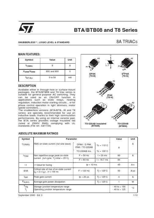
VD = VDRM RL = 3.3 kΩ Tj = 125°C IT = 100 mA IG = 1.2 IGT
■
STANDARD (4 Quadrants)
Symbol Test Conditions Quadrant BTA/BTB08 C IGT (1) V D = 12 V VGT VGD IH (2) IL dV/dt (2) V D = VDRM RL = 3.3 kΩ Tj = 125°C IT = 500 mA IG = 1.2 IGT V D = 67 %VDRM gate open Tj = 125°C Tj = 125°C I - III - IV II MIN. MIN. RL = 30 Ω I - II - III IV ALL ALL MAX. MAX. MIN. MAX. MAX. 25 40 80 200 5 25 50 1.3 0.2 50 50 100 400 10 V/µs V/µs B 50 100 mA V V mA mA Unit
(dV/dt)c (2) (dI/dt)c = 3.5 A/ms
STATIC CHARACTERISTICS
Symbol VTM (2) Vto (2) Rd (2) I DRM I RRM
Note 1: minimum IGT is guaranted at 5% of IGT max. Note 2: for both polarities of A2 referenced to A1
Type Standard Snubberless Standard Snubberless Logic level Logic level Logic level Logic level Snubberless Snubberless Snubberless
TiNet S2024EI-S软件配置手册

TiNet S2024EI-S/H/HG 千兆以太网交换机用户手册软件配置手册1. 访问交换机2. 端口配置3. VLAN配置4. ARP功能配置5. DHCP功能配置6. 组播协议配置7. QOS配置8. STP功能配置9. 802.1X配置命令10. SNTP客户端配置11. Syslog配置12. 交换机管理和维护13. LLDP功能配置14. PPPoE Plus功能配置目录第1章访问交换机....................................................................................... 1-11.1 命令行接口 ............................................................................................ 1-11.1.1 命令行模式 ............................................................................ 1-21.1.2 理解命令语法......................................................................... 1-41.1.3 语法帮助................................................................................ 1-51.1.4 历史命令................................................................................ 1-61.1.5 命令中的符号......................................................................... 1-71.1.6 命令参数类型......................................................................... 1-71.2 用户管理................................................................................................ 1-81.2.1 系统缺省用户帐号 ................................................................. 1-91.2.2 增加用户帐号......................................................................... 1-91.2.3 修改密码................................................................................ 1-91.2.4 修改权限.............................................................................. 1-101.2.5 删除用户帐号........................................................................ 1-111.2.6 查看系统用户信息 ................................................................ 1-111.3 管理用户的远程认证............................................................................ 1-111.3.1 启用RADIUS远程认证....................................................... 1-121.3.2 显示认证方式配置 ............................................................... 1-121.4 管理交换机的途径 ............................................................................... 1-121.4.1 通过超级终端管理交换机 .................................................... 1-121.4.2 通过telnet管理交换机 ........................................................ 1-14第2章端口配置........................................................................................... 2-12.1 端口简介................................................................................................ 2-12.2 端口配置................................................................................................ 2-12.2.1 端口的相关配置..................................................................... 2-12.2.2 进入端口配置模式 ................................................................. 2-22.2.3 打开或关闭指定端口.............................................................. 2-22.2.4 配置端口双工模式和速率 ...................................................... 2-22.2.5 配置端口优先级..................................................................... 2-32.2.6 配置端口描述......................................................................... 2-42.2.7 设置端口的速率限制.............................................................. 2-42.2.8 开启或关闭端口的VLAN收包过滤功能 ................................ 2-42.2.9 设置端口的接收帧类型.......................................................... 2-52.2.10 开启或关闭端口的流量控制功能 ......................................... 2-52.2.11 配置端口类型....................................................................... 2-62.2.12 配置trunk端口的allowed vlan ........................................... 2-62.2.13 设置trunk端口缺省VLAN ID .............................................. 2-72.2.14 将access端口加入到指定VLAN中 ................................... 2-72.2.15 显示端口信息....................................................................... 2-82.2.16 显示或清除端口统计信息 .................................................... 2-8 2.3 端口镜像................................................................................................ 2-92.3.1 端口镜像简介......................................................................... 2-92.3.2 端口镜像配置......................................................................... 2-9 2.4 端口汇聚配置....................................................................................... 2-102.4.1 端口汇聚简介........................................................................ 2-112.4.2 端口汇聚配置....................................................................... 2-12 2.5 端口CAR配置 .................................................................................... 2-152.5.1 端口CAR简介 .................................................................... 2-152.5.2 端口CAR配置任务列表...................................................... 2-152.5.3 全局开启/关闭端口CAR ...................................................... 2-162.5.4 端口开启/关闭端口CAR ...................................................... 2-162.5.5 配置端口CAR重新打开端口的时间.................................... 2-162.5.6 配置端口CAR值................................................................. 2-172.5.7 显示端口CAR信息 ............................................................. 2-17 2.6 端口利用率告警配置............................................................................ 2-182.6.1 端口利用率告警简介............................................................ 2-182.6.2 端口利用率告警配置任务列表 ............................................. 2-182.6.3 全局开启/关闭端口利用率告警............................................ 2-182.6.4 端口开启/关闭端口利用率告警............................................ 2-192.6.5 配置端口利用率的流量过大阈值和流量正常阈值................ 2-192.6.6 显示端口利用率告警信息 .................................................... 2-202.7 端口shutdown-control配置 ................................................................ 2-212.7.1 端口shutdown-control简介 ................................................ 2-212.7.2 端口shutdown-control配置任务列表.................................. 2-212.7.3 端口shutdown-control的配置............................................. 2-212.7.4 配置端口shutdown-control恢复方式.................................. 2-222.7.5 显示端口shutdown-control信息......................................... 2-222.7.6 恢复端口shutdown-control配置......................................... 2-23第3章VLAN配置........................................................................................ 3-13.1 VLAN简介 ............................................................................................. 3-13.2 VLAN端口类型 ...................................................................................... 3-13.3 缺省VLAN(Default VLAN) ............................................................... 3-23.4 VLAN配置 ............................................................................................. 3-23.4.1 VLAN配置任务列表............................................................... 3-23.4.2 创建/删除VLAN .................................................................... 3-33.4.3 增加/删除VLAN端口 ............................................................ 3-33.4.4 指定/恢复VLAN描述符......................................................... 3-43.4.5 设置端口类型......................................................................... 3-53.4.6 端口缺省VLAN ID设置......................................................... 3-53.4.7 tag vlan设置 .......................................................................... 3-63.4.8 显示VLAN信息..................................................................... 3-63.5 PVLAN ................................................................................................... 3-73.6 GVRP配置............................................................................................. 3-73.6.1 GVRP协议简介 ..................................................................... 3-73.6.2 GVRP配置任务列表 .............................................................. 3-73.6.3 全局开启/关闭GVRP ............................................................ 3-83.6.4 端口开启/关闭GVRP ............................................................ 3-83.6.5 显示GVRP状态.................................................................... 3-93.6.6 添加/删除允许GVRP动态学习的vlan .................................. 3-93.6.7 显示允许GVRP学习的vlan ............................................... 3-103.6.8 GVRP配置举例 ................................................................... 3-103.7 QinQ配置 ............................................................................................ 3-103.7.1 QinQ简介............................................................................. 3-103.7.2 QinQ配置任务列表............................................................... 3-113.7.3 配置全局的QinQ模式.......................................................... 3-113.7.4 配置端口的QinQ模式......................................................... 3-123.7.5 配置端口的动态QinQ .......................................................... 3-123.7.6 全局开启/关闭vlan-swap .................................................... 3-143.7.7 配置端口的交换vlan ........................................................... 3-143.7.8 配置端口的外层vlan改写 ................................................... 3-153.7.9 显示动态QinQ状态 ............................................................ 3-163.7.10 显示交换vlan状态 ............................................................ 3-173.7.11 显示外层vlan改写状态..................................................... 3-17第4章ARP功能配置 .................................................................................. 4-14.1 ARP功能简介 ........................................................................................ 4-14.2 ARP功能配置 ........................................................................................ 4-14.2.1 ARP功能配置列表 ................................................................. 4-14.2.2 删除ARP表项....................................................................... 4-14.2.3 显示ARP表项....................................................................... 4-1第5章组播协议配置 ................................................................................... 5-35.1 GMRP协议简介..................................................................................... 5-35.2 GMRP配置............................................................................................ 5-35.2.1 GMRP配置任务列表.............................................................. 5-35.2.2 全局开启/关闭GMRP ............................................................ 5-35.2.3 端口开启/关闭GMRP ............................................................ 5-45.2.4 显示GMRP状态 ................................................................... 5-55.2.5 添加/删除允许进行GMRP学习的多播 ................................. 5-55.2.6 显示允许进行GMRP学习的多播.......................................... 5-65.3 IGMP Snooping配置 ............................................................................. 5-65.3.1 IGMP Snooping协议简介 ...................................................... 5-65.3.2 IGMP Snooping配置 ............................................................. 5-65.3.3 IGMP Snooping动态组播端口成员老化时间配置.................. 5-75.3.4 IGMP Snooping查询最大响应时间配置 ................................ 5-75.3.5 IGMP Snooping端口快速离开功能配置 ................................ 5-85.3.6 IGMP Snooping端口学习组播数目限制配置......................... 5-85.3.7 IGMP Snooping黑白名单配置............................................... 5-85.3.8 配置IGMP Snooping混合路由端口功能............................... 5-95.3.9 配置IGMP Snooping查询器开关 ......................................... 5-95.3.10 配置IGMP Snooping查询器发送报文间隔....................... 5-105.3.11 配置IGMP Snooping通用查询发送vlan .......................... 5-105.3.12 配置IGMP Snooping通用查询最大响应时间 .................... 5-115.3.13 配置IGMP Snooping通用查询源IP .................................. 5-115.3.14 配置IGMP Snooping路由端口老化................................... 5-115.3.15 添加IGMP Snooping路由端口 ......................................... 5-125.4 静态组播配置....................................................................................... 5-125.4.1 静态组播简介....................................................................... 5-125.4.2 静态组播配置....................................................................... 5-135.5 跨vlan组播配置.................................................................................. 5-155.5.1 跨vlan组播简介.................................................................. 5-155.5.2 跨vlan组播配置.................................................................. 5-16第6章DHCP功能配置 ............................................................................... 6-16.1 DHCP功能简介 ..................................................................................... 6-16.2 DHCP功能配置 ..................................................................................... 6-16.2.1 DHCP功能配置列表 .............................................................. 6-16.2.2 启动DHCP中继.................................................................... 6-16.2.3 为VLAN 配置DHCP服务器 ................................................ 6-26.3 DHCP SNOOPING ................................................................................ 6-36.3.1 功能开启................................................................................ 6-36.3.2 配置信任端口......................................................................... 6-46.3.3 配置最大客户端数目.............................................................. 6-46.3.4 配置IP source guard ............................................................. 6-46.3.5 显示端口的DHCP SNOOPING配置信息............................ 6-46.3.6 显示VLAN的DHCP SNOOPING配置信息......................... 6-46.3.7 显示用户信息......................................................................... 6-5第7章ACL配置.......................................................................................... 7-1访问控制列表简介......................................................................................... 7-17.1.1 访问控制列表概述 ................................................................. 7-17.1.2 匹配顺序的配置..................................................................... 7-17.1.3 访问控制列表支持 ................................................................. 7-27.2 ACL配置................................................................................................ 7-37.2.1 配置任务列表......................................................................... 7-37.2.2 时间段配置 ............................................................................ 7-47.2.3 定义访问控制列表 ................................................................. 7-57.2.4 激活访问控制列表 ............................................................... 7-127.3 访问控制列表的监控与维护................................................................. 7-12第8章QOS配置......................................................................................... 8-18.1 QOS简介............................................................................................... 8-18.2 QOS配置............................................................................................... 8-48.2.1 QoS配置任务列表 ................................................................. 8-48.2.2 报文重定向配置..................................................................... 8-58.2.3 优先级标记配置..................................................................... 8-58.2.4 队列调度配置......................................................................... 8-68.2.5 设置硬件优先级队列与802.1p协议优先级的映射关系......... 8-78.2.6 流镜像配置 ............................................................................ 8-78.2.7 流量统计配置......................................................................... 8-88.2.8 报文重写vlan配置 ................................................................ 8-98.2.9 报文插入tag头配置 .............................................................. 8-98.3 QoS 的监控与维护 .............................................................................. 8-108.4 端口隔离.............................................................................................. 8-118.4.1 端口隔离简介........................................................................ 8-118.4.2 端口隔离配置........................................................................ 8-118.5 风暴控制.............................................................................................. 8-128.5.1 风暴控制简介....................................................................... 8-128.5.2 风暴控制配置....................................................................... 8-12第9章STP功能配置................................................................................... 9-19.1 STP协议简介......................................................................................... 9-19.2 STP功能配置......................................................................................... 9-19.2.1 STP功能配置任务列表 .......................................................... 9-19.2.2 开启/关闭设备STP特性 ....................................................... 9-29.2.3 开启/关闭端口STP特性 ....................................................... 9-29.2.4 配置交换机STP优先级 ........................................................ 9-39.2.5 配置交换机Forward Delay特性 ........................................... 9-39.2.6 配置交换机Hello Time特性.................................................. 9-49.2.7 配置交换机Max Age特性..................................................... 9-59.2.8 配置特定端口的路径开销 ...................................................... 9-59.2.9 配置特定端口的STP优先级 ................................................. 9-69.2.10 配置特定端口的根保护功能................................................. 9-79.2.11 配置特定端口强制发送rstp报文......................................... 9-79.2.12 配置特定端口的链路类型 .................................................... 9-79.2.13 配置特定端口的边界端口状态............................................. 9-89.2.14 配置特定端口发送BPDU的速率限制 ................................. 9-99.2.15 STP监控和维护................................................................... 9-99.2.16 开启/关闭端口的远端环路检测功能.................................... 9-119.3 MSTP协议简介.................................................................................... 9-119.4 MSTP功能配置.................................................................................... 9-129.4.1 MSTP功能配置任务列表 ..................................................... 9-129.4.2 配置MSTP的定时器参数值................................................ 9-129.4.3 配置MSTP的配置标识符 ................................................... 9-139.4.4 配置MSTP网桥优先级....................................................... 9-149.4.5 配置MSTP端口的边界端口状态 ........................................ 9-149.4.6 配置MSTP端口的链路类型................................................ 9-149.4.7 配置MSTP端口的路径花费................................................ 9-159.4.8 配置MSTP端口优先级....................................................... 9-169.4.9 配置特定端口的根保护功能................................................. 9-169.4.10 显示MSTP配置信息......................................................... 9-169.4.11 开启/关闭端口摘要侦听功能.............................................. 9-179.4.12 配置VLAN的_Ignore特性................................................ 9-18第10章802.1X配置命令 .......................................................................... 10-110.1 802.1X协议简介 ................................................................................ 10-110.2 802.1X配置 ....................................................................................... 10-110.2.1 AAA模式配置..................................................................... 10-210.2.2 配置RADIUS服务器......................................................... 10-210.2.3 配置域................................................................................ 10-510.2.4 802.1X配置........................................................................ 10-7第11章SNTP客户端配置.......................................................................... 11-111.1 SNTP协议简介 .................................................................................. 11-111.2 SNTP客户端配置............................................................................... 11-111.2.1 开启/关闭设备SNTP客户端功能 ....................................... 11-211.2.2 SNTP客户端的工作方式配置 ............................................. 11-211.2.3 SNTP客户端的单播服务器配置.......................................... 11-311.2.4 SNTP客户端的广播延时配置 ............................................. 11-311.2.5 SNTP客户端的组播TTL配置 ............................................ 11-311.2.6 SNTP客户端的轮询间隔配置 ............................................. 11-411.2.7 SNTP客户端的超时重传配置 ............................................. 11-411.2.8 SNTP客户端合法服务器列表配置 ...................................... 11-511.2.9 SNTP客户端的MD5认证配置 ........................................... 11-5第12章Syslog配置 .................................................................................. 12-112.1 Syslog简介........................................................................................ 12-112.2 Syslog配置........................................................................................ 12-112.2.1 开启/关闭设备Syslog功能................................................ 12-212.2.2 Syslog序列号显示配置...................................................... 12-212.2.3 Syslog时间戳类型配置...................................................... 12-312.2.4 Syslog终端输出配置.......................................................... 12-312.2.5 Syslog历史缓冲区输出配置............................................... 12-412.2.6 Syslog Flash存储器输出配置............................................ 12-512.2.7 Syslog日志主机输出配置 .................................................. 12-512.2.8 Syslog SNMP Agent输出配置........................................... 12-712.2.9 模块调试开关配置 ............................................................. 12-8第13章SSH配置...................................................................................... 13-113.1 SSH简介 ........................................................................................... 13-113.2 SSH配置 ........................................................................................... 13-113.2.1 开启/关闭设备SSH功能................................................... 13-113.2.2 SSH密钥配置 .................................................................... 13-213.2.3 其他 ................................................................................... 13-3第14章交换机管理和维护........................................................................ 14-114.1 配置文件管理..................................................................................... 14-114.1.1 编辑配置文件..................................................................... 14-114.1.2 修改和保存当前配置.......................................................... 14-114.1.3 擦除配置............................................................................ 14-114.1.4 执行已保存的配置 ............................................................. 14-214.1.5 显示已保存的配置 ............................................................. 14-214.1.6 显示当前配置..................................................................... 14-214.1.7 配置文件执行模式的切换 .................................................. 14-3 14.2 在线加载升级程序 ............................................................................. 14-314.2.1 通过TFTP上、下载文件 .................................................. 14-314.2.2 通过FTP上、下载文件..................................................... 14-514.2.3 通过Xmodem下载文件 .................................................... 14-6 14.3 设备管理............................................................................................ 14-714.3.1 MAC地址表管理................................................................ 14-714.3.2 重启交换机 ....................................................................... 14-11 14.4 系统维护.......................................................................................... 14-1214.4.1 show命令查看系统状态和系统信息 ................................ 14-1214.4.2 系统基本配置及管理........................................................ 14-1314.4.3 网络连接的测试命令........................................................ 14-1414.4.4 回环测试命令................................................................... 14-1514.4.5 管理IP地址限制 ............................................................. 14-1614.4.6 同时进入特权模式的Telnet用户数限制.......................... 14-1614.4.7 路由跟踪命令................................................................... 14-1714.4.8 cpu-car命令..................................................................... 14-18 14.5 利用SNMP对系统监控................................................................... 14-1814.5.1 SNMP协议介绍 ............................................................... 14-1814.5.2 SNMP配置....................................................................... 14-19 14.6 系统IP配置..................................................................................... 14-2914.6.1 管理VLAN配置............................................................... 14-2914.6.2 手工方式配置交换机IP地址 ........................................... 14-3014.6.3 BOOTP............................................................................. 14-3014.6.4 DHCP ............................................................................... 14-3114.6.5 IP地址配置举例............................................................... 14-3114.6.6 显示交换机IP地址.......................................................... 14-3214.7 开启或关闭目的地址未知报文的转发功能....................................... 14-3214.8 CPU使用率告警配置 ....................................................................... 14-3314.8.1 CPU使用率告警简介 ....................................................... 14-3314.8.2 CPU使用率告警配置任务列表......................................... 14-3314.8.3 开启/关闭CPU使用率告警 ............................................. 14-3314.8.4 配置CPU忙阈值和CPU不忙阈值................................. 14-3414.8.5 显示CPU使用率告警信息 .............................................. 14-3414.9 防DOS攻击.................................................................................... 14-3514.9.1 IP分片攻击防护............................................................... 14-35第15章LLDP功能配置........................................................................... 15-3615.1 LLDP协议简介................................................................................. 15-3615.2 LLDP功能配置................................................................................. 15-3615.2.1 LLDP功能配置任务列表.................................................. 15-3615.2.2 开启/关闭全局LLDP开关 ............................................... 15-3615.2.3 配置LLDP的hello-time .................................................. 15-3715.2.4 配置LLDP的hold-time ................................................... 15-3715.2.5 配置端口LLDP报文收发模式......................................... 15-3815.2.6 显示LLDP信息............................................................... 15-38第16章GERP功能配置 ........................................................................... 16-116.1 GERP功能介绍 ................................................................................. 16-116.2 GERP功能配置 ................................................................................. 16-116.2.1 GERP功能配置任务列表................................................... 16-116.2.2 GERP协议状态配置 .......................................................... 16-116.2.3 配置GERP定时器参数..................................................... 16-216.2.4 进入GERP配置模式 ........................................................ 16-316.2.5 配置GERP域的控制VLAN .............................................. 16-316.2.6 创建GERP环 ................................................................... 16-4。
格林耐特2008B+交换机配置应用说明
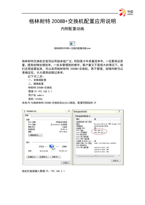
格林耐特2008B+交换机配置应用说明内附配置动画格林耐特2008B+交换机配置动画.exe格林耐特交换机在我司应用越来越广泛,特别是今年质量效率年,一定要保证质量,提高故障处理效率,一些未管理到的楼宇,客户量又不是很大的情况下,我们还想监管起来,可以采用格林耐特2008B+交换机,易于管理,故障判断可以准确定位,大大提高故障过单率。
以下分二步:一、非隔离配置二、隔离配置林耐特2008B+交换机管理IP:192.168.2.1用户名:admin密码:123456本地PC与格林耐特2008B+交换机的以太口相连,配置同网段的IP地址栏直接键入管理IP:192.168.2.1登陆后进入主页面设置密码:jtwhcisco更换可网管IP地址及设置管理VLAN为5以上为交换机管理配置完成一、非隔离配置下面点击VLAN设置下的VLAN模式启用 Change VLAN modePort 08 打TAG标记,定义8口为交换机业务上联VLAN Index NO.从01-1601不能修改,缺省VLAN 1VID:为业务VLAN号,看系统分配的VLAN特别注意:在选择其它VLAN Index NO标记号时都要按一下Read,进行读取。
事例:VLAN标记号为02,1-7口分配业务VLAN1314,非隔离状态,配置如下图。
二、隔离配置隔离配置与非隔离配置有所不同,非隔离配置1个VLAN,1个VLAN标记号即可实现多端口业务应用。
隔离配置需要对每个端口进行分配不同的VLAN标记号才能实现端口隔离。
如:1、2、3、4端口同属VLAN8,相互隔离,配置如下VLAN成员信息。
zareba 5120 电动围栏充电器用户手册说明书

Learn more about fencing by visiting our websites at: FOR OPTIMAL RESULTS, WE RECOMMEND YOU HAVE THE FOLLOWING:1. Electric Fence Tester 2. Three 6-8’ Ground Rods3. Battery Tester (For DC and Solar)4. Three Ground Rod Clamps5. 2 Two Lengths 20 KV Insulated Hook-up Wire (one long enough to connect to fence energizer to ground system and one long enough to fence energizer to fence line)WARNING: THE FOLLOWING CAN RESULT IN DECREASED FENCE PERFORMANCE1. Brush, weed and plant growth around the base of your fence.2. Improper grounding.3. Snow.4. Cracked or broken insulators.5. Fence wires that are less than 4” apart.6. Dry, rocky or sandy soils.7. Insu ciently charged battery.☐WARNING: Read ALL these instructions. Only use electric fence energizer products for the purpose intended as de ned in this manual.☐This controller must be grounded. If it should malfunction or break down, grounding reduces the risk of electrical shock by providing a path of low resistance for the electric current. Grounding this product is provided by properly installed ground rod electrically connected to the fence controller output ground terminal.☐To reduce the risk of electric shock, an AC line operated fence controller has an polarized plug (one blade wider than the other). This plug will t in a polarized outlet only one way. If the plug does not t fully in the outlet, reverse the plug. If it still does not t, contact a quali ed electrician to installthe proper outlet. Do not change the plug in any way.☐To reduce risk of electrical shock do not remove cover. Refer to service personnel.☐Never electrify barbed wire! The barbs may injure animals if they become tangled in the fence.☐Always disconnect battery-powered fence controllers from the battery before recharging the battery. Failure to do so may damage your fence controller and battery charger, and void your warranty.☐Never run more than on fence controller on the same fence line at one time. The pulses of short shock solid state fence controllers will be too close together and may be hazardous to animals and people. It will also damage your fence controllers.☐Instruct all persons how to disconnect a fence controller in case of emergency. Post signs on electric fences along public roads or near residences.☐Never disconnect wires or approach a fence during lightning storms.☐WARNING: Risk of electric shock! Do not connect an eletric fence to any other device such as a cattle trainer or a poultry trainer. Otherwise lightning striking your fence will be conducted to all other devices.☐Never connect a DC fence to an AC power supply.☐WARNING: Energizers requiring an external ground must be properly grounded.☐WARNING: Many AC energizers are internally grounded and are equipped with polarized 2 prong plugs. These plugs must never be altered and must be inserted into a properly installed, appropriate outlet. Only use a polarized extension cord. Damaged polarized plugs must be replaced with polarizedplugs. failure to follow this warning could create a safety hazard, damage the energizer, and void the warranty.☐Install fence lines powered by seperate fence energizers far enough apart to prevent contact with both fence lines at the same time. Simultaneously touching two fences powered by seperate energizers could be hazardous.☐Install fence lines powered by seperate fence energizers far enough apart to prevent contact with both fence lines at the same time. Simultaneously touching two fences powered by seperate energizers could be hazardous.☐In a double-insulated energizer, two systems of insulation are provided instead of grounding. No means of equipment ground is provided in the supply cord of a double-insulated energizer, nor shoulda means for equipment grounding be added to the energizer. Servicing of a double-insulatedenergizer requires extreme care and knowledge of the system, and should be done only by a serive personnel. Replacement parts for a double-insulated energizer must be identical to the parts they replace.IMPORTANT: Mount inside or in a waterproof enclosure (Required for AC Energizers)AC/DC Inside installationSheltered InstallationInstallationSolar T-Post Installation (applicable for speci c models)Solar Wood Post Installation (applicable for speci c models)Solar Wood Post InstallationSTEP 4: Connect to Fence LinePoly tape connectionAluminum/Steel/Poly wire connectionSTEP 5: Power Fence EnergizerNOTE: Fence energizer will be outputting voltage at this point - to avoid shock do not touch fence terminal orWoodstream gaurantees your satisfaction. You can return product with it receipt to the place of purchase within 30 days for a full refund. Proof of purchase is required for a full refund.LIMITED WARRANTYWoodstream warrants energizers based on their milage rating from the date of purchase (or date of manufacture if proof of purchase is not provided) against defects in materials and workmanship, and from damage caused by lightning. Visit our website at www. to learn more about the warranty that applies to the speci c energizer purchased.For any sized energizer, retain your receipt for proof of purchase or register your energizer online at immediately after purchase. Also, please reference the web page for a list ofCerti ed Repair Centers and instructions on returning fence controllers for service.TERMS APPLICABLE TO BOTH 30-DAY RETURN POLICY AND THE LIMITED WARRANTY. Neither the30-day return policy nor the limited warranty applies to any defect caused by improper installation,misuse, product alterations, tampering, neglect or any similar reason not related to product malfunctionsor defects in the materials or workmanship of the product. The 30-day return policy and the limited warranties are given only to the original purchaser of the product and not to any subsequent owners orto any other user or person when installed and used in accordance with the instructions found in theowner’s manual. No person is authorized to grant any warranty additional to or di erent from thiswritten warranty.To make a warranty claim, you must contact Woodstream Corp. at 800-800-1819 or regarding defective product or parts during the warranty period or contact one of the Certi ed Repair Centers listed on If you have not registered your energizer online immediately after purchase, you may need to provide additional information such as, your name, mailing address, proof of purchase date and a description ofthe problem. If the defect is covered by the limited warranty, Woodstream Corp. or a repair center willrepair or replace (at its option) the defective product or parts.NEITHER THE SELLER NOR THE MANUFACTURE SHALL HAVE LIABILITY FOR ANY ACCIDENTIAL OR CONSEQUENTIAL DAMAGES RESULTING FROM OR CAUSED BY ANY DEFECT, FAILURE OR MALFUNCTION OF ANY PRODUCT.Part # EC-ENGMANUALSERIAL NUMBER INFORMATIONThe serial number for all Woodstream Corp. fence energizers will go to a 12 digit serial number. The format for the 12 digit serial number is as follows:EC XX XX XX XXXXCategory Year Month Day Serial numberIf no sales receipt is provided with the return, we will use the date of manufacture shown in the serial number.Please contact Woodstream Corp. for all warranty claims or returns:Woodstream Corp.69 North Locust Street Lititz, PA 17543855-592-7322LIMITATION OF DAMAGESThe directions for use of this product should be followed carefully. It is impossible to eliminate all risk inherently associated with use of the product. The e ectiveness of Woodstream brands of fence controllers may depend on the e ectiveness of connections, interruption of power source, accidential grounding of wires, weatherconditions or the manner of use or application, all of which are beyond the control of Woodstream or the seller. All such risks shall be assumed by the buyer.Woodstream warrants that this product is reasonbly t for the purposes referred to in the directions for use, subject to the inherent risks referred to above. Woodstream makes no other expressed or implied warranty of tness or merchantability or any other expressed or implied warranty. IN NO CASE SHALL WOODSTREAM AND THE SELLER BE LIABLE FOR CONSEQUENTIAL, SPECIAL OR INDIRECT DAMAGES RESULTING FROM THE USE OR HANDLING OF THIS PRODUCT. WOODSTREAM AND THE SELLER OFFER THIS PRODUCT AND THE BUYER AND USER ACCEPT IT, SUBJECT TO THE FOREGOING CONDITIONS OF SALE AND WARRANTY WHICH MAY BE VARIED ONLY BY AGREEMENT IN WRITING SIGNED BY AN OFFICER OF WOODSTREAM.Some states, however, do not allow the exclusion or limitation of incidental or consequential damages, so the above limitation or exclusion may not apply to you. This limited warranty gives you speci c legal rights, and you may also have other rights which vary from state to state.。
运营级光纤驻地网解决方案光纤接入解决方案

运营级光纤驻地网解决方案-光纤接入解决方案网络拓扑:Internet出口推荐采用新格林耐特USR10-60设备(USR10-60系列路由器所有网络接口均为千兆,采用双核500MHz网络处理器,搭载256MB高速DDR2内存,共提供6个千兆口和1000Mbps的转发能力,并发带机数可达千台以上,并支持用户的流量控制、双WAN口负载均衡、策略路由、应用过滤防火墙、自动攻击防护、VPN等业务功能)完成小区出口的流量负载均衡,以及小区用户上网的管理。
核心层采用新格林耐特二层汇聚交换机S3026E-FM完成小区的接入汇聚,S3026E整机提供五个插卡槽位,可以扩展为全光交换机,支持ACL功能可屏蔽网络中的非法用户和病毒的侵入。
接入层采用新格林耐特二层接入交换机S2024BG/BF以及2008BF设备,来实现汇核心到接入层的低成本全光网络,全线产品可支持远程管理、双向带宽控制、报文安全过滤以及强大的防雷功能可为小区用户提供最流畅、最安全的上网服务。
S2000B WEB安全接入交换机重点推介:S2000B WEB安全接入交换机的产品概述:S2008B/S2016B/S2024B系列是以高性价比安全百兆/千兆接入为目标设计的运营级WEB管理接入交换机,全系列均提供二层线速转发能力、强大的安全特性、无风扇低功耗静音设计和强大的防雷能力功能。
全线产品可提供低成本的百兆光接入,其中S2024BG可提供千兆光接入,产品可提供企业网、广电网络和小区宽带等高性价比接入应用,设备规模用于运营商具有安全可靠的稳定性。
S2000B WEB安全接入交换机的产品特性:支持基于WEB的远程管理支持所有端口全线速报文转发支持报文过滤、端口限速和组播抑制等安全接入能力支持标准802.1Q提供业务和用户的标识能力支持持基于端口、802.1P、ToS和自定义TCP/UDP端口的高级队列调度,每端口支持4个优先级队列,提供FIFS、SP和WRR等多种队列调度算法完全绿色节能的接入交换机,设备空闲时自动进入节能状态全面的恶劣环境功能能力,运行温度从-15°C到55°C稳定性经过运营商大规模的应用检验S2000B WEB安全接入交换机的产品规格:S2000B WEB安全接入交换机的业务特性:S2000B WEB安全接入交换机的配置界面:端口隔离配置:(指定端口号为上行口)双向带宽控制:(设置端口出入带宽粒度32K)端口报文统计:(查看端口收发包统计)QoS流量优先级设置:MAC地址绑定:(单端口可以绑定三个MAC地址)802.1QVLAN配置:S2000B WEB安全接入交换机与H3C S15xx系列参数性能对比:S3026E-FM 全光安全汇聚交换机简介:TiNet S3026E-FM智能安全交换机是新格林耐特公司为充分满足全光网络推出的高QoS保证模块化结构的安全智能型以太网交换机,系统采用先进的ASIC,提供L2~L7层的的智能流分类和完善的服务质量(QoS),实现完备的业务控制和用户管理能力。
新格林耐特S2008(16)配置手册

12
VLAN模式设置(1)
•
VLAN模式分为Port Based VLAN和Tag Base VLAN。默认状态下为Port Based VLAN模式。如下图:
13
VLAN模式设置(2)
•
点击【Change VLAN mode】可相互切换系统VLAN模式。在Tag Base VLAN模式页 面,用户可以配置端口的Tag属性,包括Tag、Unmodify、Untag三种(默认为Untag ),如下图所示:
14
VLAN成员设置(1)
15
VLAN成员设置(2)
16
VLAN快速设置(1)
• •
该功能是在Port Based模式下进行端口隔离设置。【选择端口号】为上行端口选择,【 端口禁能】在此选项中,非勾选的端口默认为下行端口,且相互之间隔离,勾选的端口为 下行端口禁能。 例如,上行端口选择01,端口禁能选择02,点击【Update】配置。配置成功后的端口1 不能向端口2转发报文,但能向其它所有下行端口转发报文。VLAN成员如下图所示:
新格林耐特交换机成都华创科技发展有限公司2010年7月通过web登录到设备的配置页面通过网页的方式进行各项配置包括交换机管理端口设置和vlan设置等
新格林耐特交换机
成都华创科技发展有限公司 2010年7月
1
交换机的常规配置
2
访问设备
• • • • • •
访问方式 通过WEB登录到设备的配置页面,通过网页的方式进行各项配置包括交换机管理、端口 设置和VLAN设置等。您可以使用Web浏览器(建议使用Internet Explorer5.0以上) 进行操作。 登录配置 设备各网口支持WEB管理,管理IP默认为192.168.2.1,子网掩码为255.255.255.0, 默认网关为192.168.2.254。 用户登录 使用Web页面登录时,在Web 浏览器地址栏中输入设备IP 地址(注意维护管理员的PC 到设备是连通的),输入后按“回车键”,如下图:
格林耐特S2008B基本配置
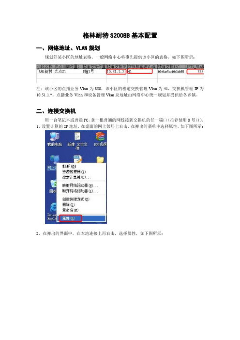
格林耐特S2008B基本配置一、网络地址、VLAN规划规划好某小区的地址表格。
一般网络中心将事先提供该小区的表格,如下图所示:注:该小区的点播业务Vlan为858,该小区的楼道交换管理Vlan为41,交换机管理IP为10.51.1.*。
点播业务Vlan和设备管理Vlan及地址由网络中心统一规划并提供给各乡镇。
二、连接交换机用一台笔记本或普通PC,拿一根普通的网线接到交换机的任一端口(推荐使用8号口)。
1、设置计算的IP地址,在桌面的网上邻居上右击,在弹出的菜单中选择属性,如下图所示:2、在弹出的界面中,在本地连接上再右击,选择属性,如下图所示:3、在中间的框框中找到,Internet协议(TCP/IP),选中后,点击下面的属性,如下图所示:4、选择使用下面的IP地址,在IP地址栏里输入:192.168.2.200(因为交换机出厂的默认地址是:192.168.2.1),为方便登录更改过后的IP地址,还要再设一个地址,点击下面的高级,如下图所示:5、点击添加,如下图所示:6、添加一个小区的交换机管理地址,如我们这个例子里的飞虹新村就是10.51.1.*的地址,我们设成10.51.1.200,填写完成后,点击“添加”,所有的窗口都点“确定”,完成计算IP 的设置。
三、配置交换机1、打开浏览器,在地址栏里输入:192.168.2.1,回车,如下图所示:2、在出现的登录界面中输入用户名和密码,默认是:admin,123456,输好后点击“OK”.3、对于一般基本的配置我们只用到“交换机管理”和“VLAN设置”这两项,点击可展开子菜单,如下图所示:4、在“交换机管理”展开的子菜单中,我们一般常用前面三个,如下图所示:5、点击“口令设置”,可以修改登录该交换机的用户名和密码,改好后点击“Update”。
6、点击“系统IP设置”,可以修改该交换机的IP地址,注意掩码和网关要设置正确。
7、点击“系统状态”可以查看交换机的MAC地址,软件版本,按要求把该交换机的MAC地址填入EXCEL表格。
兰贝208电话交换机模块说明书

目录注意事项、技术事项清除特许拨号字头名称和位置、术语和符号弹性编码功能设置指令表更改分机号码系统编程恢复分机号码进入系统编程设定分机打出方式更改系统密码设定分机打出方式设置开通外线取消全部分机打出方式外线分组设置拍叉簧的闪断时间设置某外线为某几部分机的专线设置分机呼出限制设置某分机只能使用某外线取消分机呼出限制设置打入时响铃分机恢复出厂状态设置值班方式使用方法设置全部外线人工值班人工值班设置全部外线电脑值班电脑值班设置某些外线为电脑值班打出设置第一值班分机拨打外线设置第二值班分机拨打内线监听语音信息征询转接录入语音信息三方通话监听音乐代接电话设定分机呼出等级及限拨字头设置离位转移设置某部分机等级取消离位转移设置全部分机等级强插和监听加入A组市话限拨字头自报分机号码清除A组市话限拨字头操作简明表加入B组市话限拨字头清除B组市话限拨字头加入特许拨号字头HL8120X-208A多媒体信息箱语音交换机模块使用手册宁波兰贝信息科技有限公司地址:电话:传真:安装注意事项,请仔细阅读:1、注意事项①本机应安装在干燥、通风、平稳、牢固的室内地方,布线使用专用电话线与本机连接。
②请勿将交换机与其它产生大电磁干扰源的设备(如马达、大变压器等)放置一起。
③所有分机配线必须避免与电源线或天线放在同一管线。
④避免损坏电源电缆,避免水溅雨淋,如有水进入机内,立即断电确保安全。
⑤在雷电期间,不要检修室外电话线路。
电源及接地:可靠稳定的电源是系统正常运行的保证,本系统工作电压为交流220V±10%50HZ,50,建议用户在安装本机时,使用独立于其他设备的电源,在电源电压不稳定的地区,建议使用交流稳压电源。
本机配有防雷装置,但要求有可靠的接地,否则防雷将不起作用。
技术参数:电源电压:AC220V±10% 50HZ功耗:≤20V A 交换制式:模拟空分电话机类型:双音多频拨号方式:音频方式外线音:电信局音源内线拨号音:450HZ 正弦波连续内线回铃音:450HZ 正弦波一秒通四秒断(IS:4S)系统功能设置:总机要用双音频电话机,系统编程必须在1号端口操作,进入系统编程须输入系统密码。
布朗安防系统D9000、G和GV2系列产品说明书补充
EN Owner’s Manual Supplement D9000, G & GV2 SeriesContents1.0Introduction (3)2.0Two-Man Rule (3)2.1Description (3)2.2Using the Two-Man Rule (3)3.0Early Ambush (4)3.1Description (4)3.2Using Early Ambush (4)4.0Easy Exit Control (5)4.1Description (5)4.2Using Easy Exit Control (5)5.0 Passcode Follows Scope (6)5.1Description (6)5.2Using Passcode Follows Scope (6)6.0Passcode-Controlled Menu (7)6.1Description (7)6.2Using Passcode Controlled Menus (7)7.0Invisible Walk Test (8)7.1Description (8)7.2Using Invisible Walk Test: (8)8.0 Door Activated Custom Function (10)8.1Description (10)8.2Using Door Activated Custom Functions: (10)9.0Access Level Control (10)10.0Door Control (12)10.2Using Door Control? (12)10.3Cycle Door? (13)10.4Unlock Door? (14)11.0Delete User [COMMAND 53] (15)12.0Add/Change User - [COMMAND 56] (17)12.1Description (17)2 Bosch Security Systems | 5/05 | 33267FBosch Security Systems | 5/05 | 33267F31.0 IntroductionThis document supplements the Security System Owner’s Manual(P/N: 71-06633-000) with the Function List features for the D9000 Series. The instructions for the commands listed in this document replace those commands in the Security System Owner’s Manual . Refer to the Owner’s Manual for the operation of your new security system and its other basic Function List features.2.0 Two-Man Rule2.1 DescriptionThe Two-Man Rule adds an extra step to the disarm process by requiring two unique pass codes to disarm an area from the same keypad. Configure this feature according to the guidelines specified in theD9412GV2/D7412GV2 Program Entry Guide (P/N: F01U003636).I have this feature.I do not have this feature.2.2Using the Two-Man Rule 1.Ensure the keypad shows idle armed text. 2.Enter a valid pass code with the authority to Passcode Disarm by pressing the [passcode digits] followed by the [ENTER] key. 3.The keypad shows a request for the SECOND CODE: 4. Enter a second valid pass code with the authority to PasscodeDisarm by pressing the [passcode digits] followed by the[ENTER] key. The second pass code must be different from thefirst pass code.The area is disarmed and ready for entry.3.0 Early Ambush3.1 DescriptionEarly Ambush adds an extra step to the disarm process by requiring an additional pass code to be entered to confirm the area is secure. The second pass code can be same as the first or a different one, depending on the configuration. The first entry disarms the area and the second entry stops an automatic timer from sending a duress event. Configured this feature according to the guidelines specified in the D9412GV2/D7412GV2 Program Entry Guide (P/N: F01U003636).I have this feature.I do not have this feature.3.2 Using Early Ambush1. Ensure the keypad shows idle armed text.2. Enter a valid pass code with the authority to Passcode Disarm bypressing the [passcode digits] followed by the [ENTER] key.3. Ensure the keypad shows idle disarmed text.4. The user can now search the area; however, the user must returnbefore the preset Early Ambush Time expires.5. Enter a second valid pass code with the authority to PasscodeDisarm by pressing the [passcode digits] followed by the[ENTER] key.6. The keypad shows confirmation that the second passcode wasaccepted and that the Early Ambush Window was canceled byshowing CODE 2 VALIDATED.The area is disarmed and ready for entry.4 Bosch Security Systems | 5/05 | 33267F4.0 Easy ExitControl4.1 DescriptionThe D9412GV2 / D7412GV2 Control Panels change from one armed state to another armed state without disarming. The Easy Exit Control feature reduces the number of keystrokes and simplifies system operation. This feature is available by default and is always on.4.2 Using Easy Exit ControlSwitching armed states from Master to Perimeter:1. Ensure the keypad shows idle master armed text.the[COMMAND] key. The keypad shows SYSTEM2. PressCOMMAND.3. Press [3] to Perimeter Arm.4. The keypad display shows the Exit Delay count down.5. Enter or exit the premises.Switching armed states from Perimeter to Master:1. Ensure the keypad shows idle perimeter armed text.2. Press the [COMMAND] key. The keypad shows SYSTEMCOMMAND.3. Press [1] to Master Arm.4. The keypad shows the Exit Delay count down.5. Enter or exit the premises.Bosch Security Systems | 5/05 | 33267F 55.0 PasscodeFollows Scope5.1 DescriptionThe Passcode Follows Scope feature is an optional arming and disarming restriction that can be enabled on keypads with access to multiple areas. When this feature is set to No, the keypad restricts Passcode Arming and Passcode Disarming to the home area of the keypad. When set to Yes, this feature allows users to arm or disarm all the areas that they and the keypad have access to. This feature causes no restrictions to the keypad scope as it pertains to any other command or arming method other than Passcode Arming or Passcode Disarming.I have this feature.I do not have this feature.5.2 Using Passcode Follows ScopeArming from a keypad with Panel Wide scope and Passcode Follows Scope enabled:1. Ensure the keypad shows idle disarmed text.2. Ensure you have a valid pass code with the authority to PasscodeArm in all areas.3. Enter your code by pressing the [passcode digits] followed by the[ENTER] key.4. The keypad shows ARMING: 12345678, to indicate which areasare about to enter exit delay and arm.5. The keypad shows the exit delay count down.6. Exit the premises.6 Bosch Security Systems | 5/05 | 33267FArming from a keypad with Panel Wide scope and Passcode Follows Scope disabled (default):1. Ensure the keypad shows idle disarmed text.2. Ensure you have a valid pass code with the authority to PasscodeArm in all areas.3. Enter your code by pressing the [passcode digits] followed by the[ENTER] key.4. The keypad shows the exit delay count down.5. Exit the premises.6.0 Passcode-Controlled Menu6.1 DescriptionWhen enabled, the system prompts users to enter a passcode before viewing the keypad function list menu. The system shows the user the menu options allowed according to their authority level; thereby, providing users only the commands and functions pertinent to them. Configure this feature according to the guidelines specified in theD9412GV2/D7412GV2 Program Entry Guide (P/N: F01U003636).I have this feature.I do not have this feature.6.2 Using Passcode Controlled MenusOn a D1255 keypad with the Passcode Controlled Menu enabled:1. Press the [ESC] key. The keypad responds with the ENTERPASSCODE display.2. Enter your code by pressing the [passcode digits] followed by the[ENT] key. The first menu item that you have authority to useappears.Bosch Security Systems | 5/05 | 33267F 7On a D1260 keypad with the Passcode Controlled Menu enabled:1. Press the [Menu>] soft key in the lower right corner. The keypadresponds with the Enter passcode: then press [ENTER] display. 2. Enter your code by pressing the [passcode digits] followed by the[ENTER] key.The first and second menu items that you have authority to use appear. 7.0 Invisible WalkTest7.1 DescriptionThe D9412GV2 / D7412GV2 has a function list menu item that allows the user to test invisible interior or perimeter controlled points that are within the scope of the keypad without sending a report to the central station. This is identical to the Service Walk Test except that it is restricted to invisible points.I have this feature.I do not have this feature.7.2 Using Invisible Walk Test:On a D1255 keypad with the Passcode Controlled Menu enabled:1. Press the [ESC] key.2. Press the [NEXT] key until INVISIBLE TEST?appears.3. Press the [ENT] key to activate the Invisible Walk Test function.The keypad shows the number of invisible points within the scopeof the keypad:### PTS TO TEST4. Press the [NEXT] key to see VIEW UNTESTED?.5. Press the [ENT] key to view the untested points. The keypadshows the total number of untested invisible points within thekeypad scope:### PTS UNTESTED.6. Press the [NEXT] key to view the first point’s name.8 Bosch Security Systems | 5/05 | 33267F7. Press the [ENT] key to view the point’s hardware state:1PT### NORMAL HW if it is normal1PT### OPEN HW if it is opened1PT### SHORT HW if it is shorted1PT### MISSNG HW if it is missing 8. Activate the point’s sensor and observe the appropriate statechange.9. Press the [NEXT] key to advance to the next invisible pointwithin the scope of the keypad.10. Repeat steps 7 through 9 until all points are tested.On a D1260 keypad with the Passcode Controlled Menu enabled:the[Menu>]soft key in the lower right corner.1. Press2. Press the [Next>] soft key until the Invisible Walk Test?appears.3. Press the corresponding soft key to activate the InvisibleWalk Test function. The keypad shows the number of invisiblepoints within the scope of the keypad:### points remain to betested.5. Press the [View untested pts>] soft key to see 6 pts untested.6. Press the [Next Pt>] soft key to view the first or next untestedpoint:[Point Text]Area #, Pt #[Point State] HW Next PT><Exit Prev PT>7. Where [Point State] can be NORMAL,OPEN,SHORT, or MISSNG.8. Activate the point’s sensor and observe the appropriate statechange.9. Repeat Steps 5 through 8 until all points are tested.Bosch Security Systems | 5/05 | 33267F 98.0 Door ActivatedCustom Function8.1 DescriptionThe D9412GV2 / D7412GV2 allow a custom function to be activated when user credentials are presented to a D9210B Door Controller Reader. The custom function executes as if the user performed a function at the keypad that is associated with the door controller.I have this feature.I do not have this feature.8.2 Using Door Activated Custom Functions:Executing the door’s custom function by a user that has authority to do so when disarming the area:1. Ensure the area you are about to enter is armed.2. Present your user credentials to the D9210B Door ControllerReader. The area disarms and the custom function executes.The area is now safe to enter.9.0 Access LevelControl9.1 DescriptionUse this function to manually enable or disable access authority levels assigned to users. This function can be used to temporarily disable a user’s access level instead of deleting and adding the user.I have this feature.I do not have this feature.10 Bosch Security Systems | 5/05 | 33267F9.2 UsingACCESS LEVEL CTL?1. Ensure the display shows idle disarmed text.2. Press the [MENU] key to enter the Function List, then press[NEXT] repeatedly until you reach the CHANGE LEVELCTL?prompt. Press [ENT].3. ACCESS LEVEL CTL appears indicating that you are affectingthe authority levels of cards or tokens and not passcodes. Press[ENT].4. ENTER LEVEL:appears. Enter the access authority level numberand press [ENT].5. If the access level is currently disabled, LEVEL # ENABLE?appears. If the access level is currently enabled, LEVEL #DISABLE?appears. Press [ENT] to accept the choice. ENTERLEVEL:appears again. Press [ESC].Bosch Security Systems | 5/05 | 33267F 1110.0 Door Control10.1 DescriptionThere are three sub-functions within the door control function. They are CYCLE DOOR?, UNLOCK DOOR? and SECURE DOOR?.CYCLE DOOR? momentarily unlocks a door to allow a person into an area. UNLOCK DOOR? unlocks a door to allow free access.SECURE DOOR? unlocks a door and prohibits access regardless of a user’s authority level.I have this feature.I do not have this feature.10.2 Using Door Control?1. Ensure the display shows idle disarmed text.2. Press the [COMMAND] key. The display shows SYSTEMCOMMAND.4. The first sub-function that appears is CYCLE DOOR?You cancycle through the three sub-functions by pressing [PREV] and[NEXT].12 Bosch Security Systems | 5/05 | 33267F10.3 Cycle Door?1. To momentarily unlock an access door and allow a person into anarea, press [ENT] at the Cycle Door? prompt.The display shows CYCLE 1 2 3 4 5 6 7 8if all doors are ina normal state and available. If a door is not in a normal state, thenumber of the door is replaced with one of the symbols indicatedin Table 1.Table 1: Key to SymbolsSymbol Description---Door is not active, not in scope, or user doesnot have access level authorityC Door is timed door sequenceU Strike and shunt are latched active (held open)X Strike and shunt are deactivated (secured)P There is a problem with the door; call yoursecurity company2. Enter the number of the door to cycle then press [ENT]. Thisdoor cycles and the display changes to reflect the new status ofthe doors. For example, to cycle Door 3, at the following prompt:CYCLE DOOR 1 2 3 4 5 6 7 8press [3], then [ENT]. The display shows:CYCLE DOOR 1 2 C 4 5 6 7 8Thisindicates that all doors are in a normal state, except for Door 3, which is cycled.[ESC]to leave this subfunction, or enter another door3. Pressnumber to cycle.Bosch Security Systems | 5/05 | 33267F 1310.4 Unlock Door?1. To unlock a door to allow free access, at the CYCLE DOOR?prompt, press [NEXT] to enter the UNLOCK DOOR?subfunction.The display shows UNLOCK 1 2 3 4 5 6 7 8if all doors arein a normal state and available. If a door is not in a normal state,the number of the door is replaced with a symbol indicated inTable 1.2. Enter the number of the door to unlock then press [ENT]. Thisdoor unlocks and the display changes to reflect the new status ofthe doors.For example, if you wanted to unlock Door 4, at the followingprompt:UNLOCK DOOR 1 2 3 4 5 6 7 8press [4]then [ENT]. The display shows:UNLOCK DOOR 1 2 3 U 5 6 7 8This indicates that all doors are in a normal state, except for Door4, which is unlocked.4. Press [ESC] to leave this subfunction, or enter another doornumber to unlock.10.5 Secure Door?1. To secure a door to prohibit access to users regardless of theiraccess authority level, at the CYCLE DOOR?prompt, press[PREV] to enter the SECURE DOOR?subfunction.The display shows SECURE 1 2 3 4 5 6 7 8if all doors arein a normal state and available. If a door is not in a normal state,the number of the door is replaced with a symbol indicated inTable 1 on page 12.2. Enter the number of the door to secure then press [ENT]. Thisdoor secures, and the display changes to reflect the new status ofthe doors.For example, to secure Door 5, at the following prompt:SECURE DOOR 1 2 3 4 5 6 7 8Press [5] then [ENT]. The display shows:SECURE DOOR 1 2 3 4 X 6 7 814 Bosch Security Systems | 5/05 | 33267FBosch Security Systems | 5/05 | 33267F15This indicates that all doors are in a normal state, except for Door 5, which is secured. Press [ESC] to leave this subfunction, or enter another door11.0 Delete User[COMMAND 53] 11.1 DescriptionUse this function to delete a personal passcode from your system without assistance from your security company. You must know the user number for the passcode you want to delete.I have this feature.I do not have this feature.11.2 Using DEL USER ?1.Ensure the display shows idle disarmed text. 2.Press the [COMMAND] bar. The display shows SYSTEM COMMAND . 3. Press [5] and [3].4. The display shows DEL USER #. Enter the user number and press[ENT].5. USER ##(or user text, such as the name of the user, if this featurewas programmed into your system by your security company)appears allowing for confirmation. Press [ENT].If this is not theuser you wish to delete, press the [NEXT] or [PREV] key until thecorrect user name appears, then press [ENT].6. The display shows DELETE USER ##? Press [ENT] to delete user,and USER DELETED appears. If the user number is not in thesystem, NOT IN USE appears. If you made an error and do notwish to delete this user, press [ESC].16 Bosch Security Systems | 5/05 | 33267F12.0 Add/ChangeUser - [COMMAND 56]12.1 DescriptionUse this function to add or change a passcode or card without assistance from your security company. Before adding or changing a passcode orcard, you must know which user numbers are available, the authority level you want to assign to the new user, and the areas in which the passcode or card are valid.I have this feature.I do not have this feature.12.2 Using Add User ?1. Ensure the display shows idle disarmed text.2. Press the [COMMAND] bar. The display shows SYSTEMCOMMAND.3. Press [5] and [6].4. The display shows ENTER USER #. Enter the user number andpress [ENT].5. The display shows USER # (or user text, such as the name of theuser, if this feature was programmed into your system by yoursecurity company) to allow for confirmation. Press [ENT] if thecorrect user number (or user name) appears. Press [ESC] if not.6.ADD PASSCODE?appears (If the user number already exists,CHANGE PASSCODE?appears). Press [ENT].ENTER NEW CODEBosch Security Systems | 5/05 | 33267F 17appears. Enter the new passcode followed by [ENT].ENTERAGAIN appears. Enter the new passcode a second time forconfirmation. Press [ENT]. The display shows PASSCODE ADDED(or PASSCODE CHANGED if the user number was already in theSystems With Access Control...7. ADD LEVEL?(CHANGE LEVEL?If the user number alreadyexists) appears. Press [ENT].8. VALID AREA 1? appears. If you wish this user number to bevalid in Area 1, press [ENT]. If not, press [NEXT].9. AUTH LEVEL appears. Assign the authority level you wish theuser number to have for this area and press [ENT]. Record thisinformation.10. VALID AREA 2? appears. Enter the information necessary forthe areas in the scope of the keypad by following steps 8 and 9 foreach area (up to 8 areas). LEVEL ADDED(or LEVEL CHANGED)appears when all area assignments are made. Press [ENT].18 Bosch Security Systems | 5/05 | 33267FBosch Security Systems | 5/05 | 33267F 19。
新格林耐特8口交换机精简配置说明.
S2008EI-S交换机手动配置命令最精简方式:一、访问交换机使用超级终端(或者仿终端软件)连接到交换机的Console口,从而通过超级终端来访问系统的命令行接口(CLI)。
批处理配置(把做好的脚本命令一起粘贴到超级终端时的行为):修改串口连接设备:使用串口线连接,打开超级终端。
新建连接后,在端口设置里面先点击还原默认值,然后再把波特率修改为9600。
(这一点非常总要)。
需要注意如果需要粘贴配置,需要配置行延时和字符延时(点击文件属性设置 ASCII码设置行延时填写100毫秒字符延时20毫秒)。
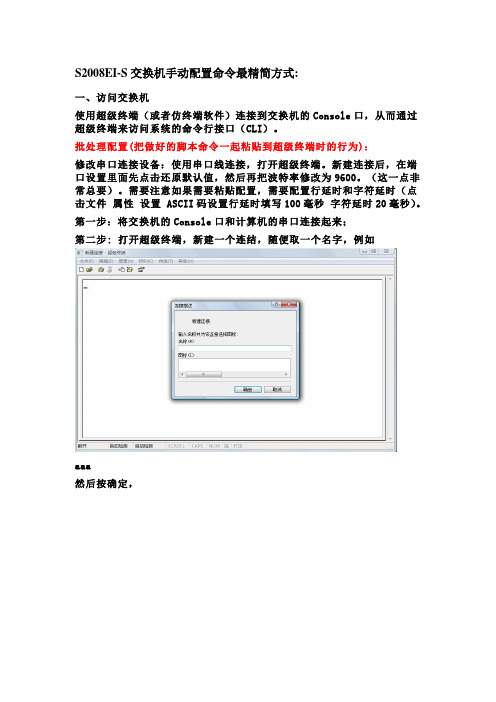
第一步:将交换机的Console口和计算机的串口连接起来;第二步: 打开超级终端,新建一个连结,随便取一个名字,例如aaa然后按确定,然后选择COM口,按确定,端口设置选择为还原为默认值,再确定第二步:此时就可以以看到登录提示信息:Username(1-32 chars):第三步:输入正确的用户名,按回车,在提示下再输入相应密码。
如果是首次登录交换机,就应该使用缺省的用户名admin登录,此时输入登录密码123456,以系统管理员的身份进行操作。
第四步:成功登录交换机后,系统显示如下信息:TiNet>第五步:输入enable回车,系统显示如下信息:TiNet# 说明:特权模式第六步:输入configure terminal回车,系统显示如下信息:TiNet(config)# 说明:配置模式,请在此模式下进行配置TiNet(config)#ipaddress 172.20.100.10 255.255.255.0 172.20.100.1 说明:配置交换机IP地址这样通过IP地址,我们可能在WEB页面配置交换机了,但我们不建议在配置开始就用IP地址去配置,出于安全、稳定性的考虑,交换机的WEB页面并没把全部命令都加进去,还有不少的配置与调试信息都在命令行里。
另外,为了安全考虑,本地交换机的各端口默认VLAN 都不在管理VLAN里,这样,直接用网线接交换机会无法访问。
新格林耐特配置命令
第一部分:TiNetS2000EI系列配置命令及说明(红色标识为一些常用命令)Username(1-32chars):adminPassword(1-16chars):******/登陆交换机,默认密码123456/TiNet>enable/进入特权模式/TiNet#configureterminal/进入全局模式/TiNet(config)#1.TINET#terminallanguage/改变语言模式/例如:TINET#terminallanguageChinese/改成中文模式/2.TiNet#clearstartup-config/清除配置,恢复出厂默设置/3.4.5./6.7.8.9./ 10.11.12./端口为trunk模式,允许所有VLAN通过/13.TiNet(config-if-ethernet-0/2)#switchportaccessvlan1001/改变端口PVID/14.TiNet(config)#port-isolationethernet?STRING<3-4>端口号为槽端口号<0-2>/端口号<1-24>TiNet(config)#port-isolationethernet0/2toe0/16添加端口隔离下行端口成功./一步隔离,一条命令隔离除上行口以外所有端口/15.TiNet(config)#interfacerangeethernet0/2toethernet0/16/批量端口处理命令/16.TiNet(config-if-range)#bandwidth-control?egress出口带宽控制ingress入口带宽控制/端口限速命令/17.TiNet(config)#showutilizationinterface/实时查看端口流量占比/LinkUtilizationAveragesThuJan100:43:201970portlinkReceivePeakRxTransmitPeakTxStatuspkts/secpkts/secpkts/secpkts/sec==================================================================e0/1down0000e0/2down0000e0/3down0000e0/4down0000e0/5down0000e0/6down000018.简要流程/配置ip地址/ConfigIPsuccessfully.TiNet(config)#showipSwitchconfigurationipobtained:MANUALnetmask:ManageVLAN:1MACaddress:00:0a:5a:11:ba:b8/查看交换机ip地址/TiNet(config)#exTiNet#terminallanguagechinese/更改语言模式为中文/TiNet(config)#vlan3901/建立vlan3901/TiNet(config-if-vlan)#switchportall/在vlan3901下添加端口/添加VLAN端口成功!TiNet(config)#ipaddressvlan3901/定义交换机管理vlan/配置管理VLAN成功!TiNet(config)#showip交换机的配置信息IP地址获得方式:MANUAL管理VLAN:13901/此时管理vlan为1和3901/MAC地址:00:0a:5a:11:ba:b8IP管理MAC添加显示添加TiNet(config-if-vlan)#showvlan1015显示VLAN信息VLANID:1015VLANstatus:staticVLANmember:e0/1,e0/16.Statictaggedports:StaticuntaggedPorts:e0/1,e0/16.Dynamictaggedports:TiNet(config)#port-isolationethernet0/2toe0/16/端口2-16进行隔离,1口为上行口,未隔离/添加端口隔离下行端口成功.TiNet(config-if-ethernet-0/1)#switchport?accessaccess端口backup配置备份端口mode端口模式trunktrunk端口TiNet(config-if-ethernet-0/1)#switchportmodetrunk/更改端口1模式为trunk/ TiNet(config-if-ethernet-0/1)#switchporttrunkallowedvlanall/允许所有vlan通过1口/ TiNet(config-if-ethernet-0/1)#switchporttrunknativevlan3901/更改1口pvid为3901/请输入您的登录密码:******请输入用户名(4--15位):admin请输入新口令(1--15位):******输入确认口令(1--15位):******/用户admin密码修改成功/ TiNet#copyrunning-configstartup-config/保存配置命令/第二部分:交换机实现telnet管理配置步骤第一步:配置规划好的交换机ip地址例:/配置ip地址/ConfigIPsuccessfully.TiNet(config)#showipSwitchconfigurationipobtained:MANUALManageVLAN:1MACaddress:00:0a:5a:11:ba:b8/查看交换机ip地址/第二步:建立规划好的管理vlan,把上行口加入到管理vlan中,然后删除默认的管理vlan1 例:TiNet(config)#vlan3901/建立vlan3901/TiNet(config-if-vlan)#switchporte0/1/在vlan3901中添加端口1/添加VLAN端口成功!IP管理MAC例:。
AT4202 04 08多路温度测试仪用户手册说明书

用户手册User’s GuideAT4202/04/08多路温度测试仪Rev.B4固件说明:适用于主程序RevA2.0及以上的版本@Instruments常州安柏精密仪器有限公司.江苏省常州市钟楼区宝龙61-3层销售服务电子邮件: *****************技术支持电子邮件: ****************©2005-2015 Applent Instruments Ltd.AT4202/4204/4208 用户手册2声明根据国际版权法,未经常州安柏精密仪器有限公司(Applent Instruments Inc.)事先允许和书面同意,不得以任何形式复制本文内容。
安全信息为避免可能的电击和人身安全,请遵循以下指南进行操作。
免责声明用户在开始使用仪器前请仔细阅读以下安全信息,对于用户由于未遵守下列条款而造成的人身安全和财产损失,安柏仪器将不承担任何责任。
仪器接地 为防止电击危险,请连接好电源地线。
不可在爆炸性气体环境使用仪器不可在易燃易爆气体、蒸汽或多灰尘的环境下使用仪器。
在此类环境使用任何电子设备,都是对人身安全的冒险。
不可打开仪器外壳非专业维护人员不可打开仪器外壳,以试图维修仪器。
仪器在关机后一段时间内仍存在未释放干净的电荷,这可能对人身造成电击危险。
不要超出本说明书指定的方式使用仪器超出范围,仪器所提供的保护措施将失效。
警告:不要加直流电压或电流到测试端,否则会损坏仪器。
安全标志:设备由双重绝缘或加强绝缘保护废弃电气和电子设备 (WEEE) 指令 2002/96/EC切勿丢弃在垃圾桶内有限担保和责任范围 3有限担保和责任范围常州安柏精密仪器有限公司(以下简称Applent)保证您购买的每一台AT4202/4204/4208在质量和计量上都是完全合格的。
此项保证不包括保险丝以及因疏忽、误用、污染、意外或非正常状况使用造成的损坏。
本项保证仅适用于原购买者,并且不可转让。
自发货之日起,Applent提供玖拾(90)天保换和贰年免费保修,此保证也包括VFD或LCD。
格林威尔B120B设备PCM说明书

目录1 概述............................................................................... - 3 -1.1 什么是MST?................................................................................... - 3 -1.2 B120B的主要特点 ............................................................................. - 3 -2 组网及应用 ......................................................................... -3 -2.1 传统话音业务的接入.......................................................................... - 3 -2.2 数据及其它业务的接入与混传................................................................. - 4 -2.3 灵活可变的单路接入.......................................................................... - 4 -2.4 512×512的全数字交叉......................................................................... - 4 -2.5 E1通道保护功能 .............................................................................. - 5 -2.6 与MST-B120/MST-A15的结合使用 .............................................................. - 6 -3 技术指标 ........................................................................... - 6 -3.1 E1接口规范................................................................................... - 6 -3.2 局端电话接口卡(MBFXO)/用户端电话接口卡(MBFXS)规范...................................... - 6 -3.3 热线电话接口卡(MBPRA)规范.................................................................. - 7 -3.4 磁石电话接口卡(MBMAG)规范.................................................................. - 7 -3.5 EM2/4线接口卡(MBEM2/4)规范................................................................. - 7 -3.6 64K同向接口卡(MB64K)规范................................................................... - 7 -3.7 V.24接口卡(MBV24)规范 ...................................................................... - 7 -3.8 V.35接口卡(MBV35)规范 ...................................................................... - 7 -3.9 以太网接口卡(MB10Base-T)规范 .............................................................. - 7 -3.10 基带传输卡(MB2B)规范 ...................................................................... - 8 -3.11 DSL小卡(MBDSL)规范......................................................................... - 8 -3.12 网管接口规范................................................................................ - 8 -3.13 机箱尺寸、重量 ............................................................................. - 8 -3.14 功耗......................................................................................... - 8 -4 设备组成 ........................................................................... - 8 -4.1 主机说明 ..................................................................................... - 8 -4.2 单元盘说明................................................................................... - 9 -4.3 后面板说明.................................................................................. - 12 -5 用户接口卡 .........................................................................- 13 -5.1 局端电话接口卡(MBFXO) ..................................................................... - 13 -5.2 用户端电话接口卡(MBFXS)................................................................... - 13 -5.3 热线电话接口卡(MBPRA) ..................................................................... - 13 -5.4 磁石电话接口卡(MBMAG) ..................................................................... - 13 -5.5 EM2/4线接口卡(MBEM2/4) .................................................................... - 14 -5.6 64K同向接口卡(MB64K)....................................................................... - 15 -5.7 V.24接口卡(MBV24).......................................................................... - 15 -5.8 V.35接口卡(MBV35).......................................................................... - 16 -5.9 以太网接口卡(MB10Base-T).................................................................. - 17 -5.10 基带传输卡(MB2B).......................................................................... - 17 -5.11 MBDSL接口卡(MBDSL)........................................................................ - 18 -6 安装...............................................................................- 18 -6.1 包装方式 .................................................................................... - 18 -6.2 安装所需工具................................................................................ - 18 -6.3 机械安装 .................................................................................... - 18 -6.4 电气安装 .................................................................................... - 18 -7 开关设置 ...........................................................................- 21 -7.1 时钟开关设置................................................................................ - 21 -7.2 网络号、节点号(站号)开关设置 ............................................................. - 22 -8 网管设置 ...........................................................................- 22 -9 B120B设备传输故障汇总...............................................................- 23 -10 设备识别 ..........................................................................- 24 -10.1 零器件识别................................................................................. - 24 -10.2 板卡识别................................................................................... - 25 -1概述1.1什么是MST?MST(Multi-Service Terminal)综合业务复用设备是使用专用集成电路芯片研制生产的多业务接口设备。
E103-W08 产品规格书说明书

E103-W08产品规格书2.4G串口WIFI BLE配网低功耗目录第一章概述 (1)1.1简介 (1)1.2功能特点 (1)1.3应用场景 (2)第二章规格参数 (2)2.1极限参数 (2)2.2工作参数 (2)第三章机械尺寸与引脚定义 (3)3.1E103-W08A引脚尺寸图 (3)3.2E103-W08A引脚尺寸图 (4)第四章推荐连线图 (5)第五章功能说明 (5)5.1工作模式 (5)5.1.1TCP通信 (6)5.1.2MQTT通信 (7)5.1.3HTTP通信 (7)5.2TCP心跳包 (7)5.3自动连接 (7)5.4手动连接 (8)5.5手动断开 (8)5.6BLE配网 (8)5.7状态指示 (8)5.8低功耗 (8)5.9注意事项 (9)第六章默认参数 (9)第七章AT指令及参数 (10)7.1错误码表 (11)7.2基本AT指令 (11)7.2.1AT测试指令 (11)7.2.2重启模块 (11)7.2.3恢复出厂参数 (12)7.2.4查询版本信息 (12)7.2.5查询、设置串口参数 (12)7.2.6查询、设置工作模式 (12)7.2.7查询、设置电源模式 (13)7.3WIFI相关AT指令 (13)7.3.1扫描可用AP (13)7.3.2连接到指定AP (13)7.3.3与AP断开连接 (14)7.3.4查询、设置连接模式 (14)7.3.5查询MAC地址 (14)7.3.6查询、设置主机名 (14)7.4TCP相关AT指令 (15)7.4.1查询网络连接状态 (15)7.4.2建立TCP传输 (15)7.4.3关闭TCP传输 (15)7.4.4查询本地IP (15)7.4.5查询、设置多连接 (15)7.4.6查询、设置TCP模式 (15)7.4.7查询、设置是否打印对端IP、端口 (16)7.4.8查询、设置远程目标参数 (16)7.4.9查询、设置心跳数据 (16)7.5MQTT相关AT指令 (17)7.5.1查询、设置MQTT远程目标 (17)7.5.2查询、设置MQTT发布主题 (17)7.5.3查询、设置MQTT订阅主题 (17)7.5.4查询、设置MQTT登录参数 (17)7.5.5查询、设置MQTT连接参数 (18)7.6HTTP相关参数 (18)7.6.1查询、设置远程目标 (18)7.6.2查询、设置URL (18)7.6.3查询、设置数据类型 (18)7.7BLE相关参数 (19)7.7.1查询、设置BLE广播名 (19)7.7.2查询、设置BLE广播间隙 (19)第八章使用教程 (20)8.1TCP通信 (20)8.1.1透传 (20)8.1.2协议传输 (21)8.2HTTP通信 (23)8.3MQTT通信 (23)8.4BLE配网 (24)第九章焊接作业指导 (27)9.1回流焊温度 (27)9.2回流焊曲线图 (27)修订历史 (28)关于我们 (28)免责申明和版权公告本文中的信息,包括供参考的URL地址,如有变更,恕不另行通知。
新格林耐特8口交换机精简配置说明.

S2008EI-S交换机手动配置命令最精简方式:一、访问交换机使用超级终端(或者仿终端软件)连接到交换机的Console口,从而通过超级终端来访问系统的命令行接口(CLI)。
批处理配置(把做好的脚本命令一起粘贴到超级终端时的行为):修改串口连接设备:使用串口线连接,打开超级终端。
新建连接后,在端口设置里面先点击还原默认值,然后再把波特率修改为9600。
(这一点非常总要)。
需要注意如果需要粘贴配置,需要配置行延时和字符延时(点击文件属性设置 ASCII码设置行延时填写100毫秒字符延时20毫秒)。
第一步:将交换机的Console口和计算机的串口连接起来;第二步: 打开超级终端,新建一个连结,随便取一个名字,例如aaa然后按确定,然后选择COM口,按确定,端口设置选择为还原为默认值,再确定第二步:此时就可以以看到登录提示信息:Username(1-32 chars):第三步:输入正确的用户名,按回车,在提示下再输入相应密码。
如果是首次登录交换机,就应该使用缺省的用户名admin登录,此时输入登录密码123456,以系统管理员的身份进行操作。
第四步:成功登录交换机后,系统显示如下信息:TiNet>第五步:输入enable回车,系统显示如下信息:TiNet# 说明:特权模式第六步:输入configure terminal回车,系统显示如下信息:TiNet(config)# 说明:配置模式,请在此模式下进行配置TiNet(config)#ipaddress 172.20.100.10 255.255.255.0 172.20.100.1 说明:配置交换机IP地址这样通过IP地址,我们可能在WEB页面配置交换机了,但我们不建议在配置开始就用IP地址去配置,出于安全、稳定性的考虑,交换机的WEB页面并没把全部命令都加进去,还有不少的配置与调试信息都在命令行里。
另外,为了安全考虑,本地交换机的各端口默认VLAN 都不在管理VLAN里,这样,直接用网线接交换机会无法访问。
斯巴尔电器 SMART 商业级双燃类 Range 包括吸管(英文)说明书

48"SMART COMMERCIAL-STYLE DUAL FUEL RANGE Includes GriddleMODELS:KFDC558JMH01(Milkshake)Illus.No.Part No.Description1Literature PartsW11114331Guide,Use And CareW11114334Instructions,InstallationW11184759Guide,InternetConnectivityW11114332Guide,Quick StartW11202393Diagram,WiringW11202387Diagram,Wiring(Oven)W11202289Sheet,Tech2W11183720Assembly,ValveManifold(Left Front And LeftRear)W11036612Assembly,ValveManifold(Left Center Front AndLeft Center Rear)W10892994Assembly,ValveManifold(Right Center FrontAnd Right CenterRear)Illus.No.Part No.Description3W10903728Switch,Harness4W11121194Bracket,Manifold5W11121317Module,Spark6W11330430Tray,GriddleInsulation7W11121384Bracket,Griddle-RTD8W10892809Tube,Manifold Supply(Left)W10892804Tube,Manifold Supply(Left Center)W10892805Tube,Manifold Supply(Right Center)9W10891745Assembly,GriddleModule103196160Screw11W10115843Cover,Ignition12Box,Burner(NotServiced)13W10891584Sensor,Griddle14W10162096Screw15W11121383Insulation,Griddle164453116Adapter,MaleIllus.No.Part No.Description17W10276497Tray,Griddle Drip18W10891698Element,Griddle19W10891567Module,GriddleFOLLOWING PARTSNOT ILLUSTRATEDW11200302Harness,Main(30")W11200311Harness,Main(18")W10903727Harness,GriddleW11200329Harness,CooktopW10780278Harness,Door LockW11200318Harness,CommunicationW11242785Harness,WIFIW11212216Cord,Power9759877Retainer,Strain Relief4450800Screw,GroundingW10253333Bracket,Anti-Tip7101P485-60Screw,Anti-Tip KitW11238042Kit,LP ConversionIllus.No.Part No.Description1W11111429Panel,Cabinet Side(Left)W11111428Panel,Cabinet Side(Right)2W10892793Assembly,OrificeHolder(Left Front)W10892492Assembly,OrificeHolder(Left Rear)W11159461Assembly,OrificeHolder(Left Center Front)W10892808Assembly,OrificeHolder(Left Center Rear)W10892505Assembly,OrificeHolder(Right Center Front) W10892446Assembly,OrificeHolder(Right Center Rear) 3W10892422Orifice,Main(17.4K)(Left Front,RightCenter Front)W10892419Orifice,Main(15K)(Left Rear,Left CenterFront,Right CenterRear)W10892435Orifice,Simmer(2.6K)(Left Front,RightCenter Front)W10892438Orifice,Simmer(5K)(Left Center Rear) 4W11238757Igniter(Left Front,RightCenter Front)W11114379Igniter(Left Rear)W10892340Igniter(Left Center Front,LeftCenter Rear,RightCenter Rear)5W11291183Burner,Grate(WithWok Ring)Illus.No.Part No.Description6W11291179Burner,Grate7W11042504Bumper,Grate8W11281269Barrier,ApplianceManager9W11436331Interface,User10W11205795Cover,WIFI Outer11W10881642Bezel(Front Burners)W10883433Bezel(Rear Burners)12W10890116Manager,Appliance(Expansion)13Cap,BurnerW11121390Black(Includes6)14W10891746Spreader,Flame(High)(Left Front,RightCenter Front)W10891974Spreader,Flame(Low)(Left Rear,Left CenterFront,Right CenterRear)W10891978Spreader,Flame(AUX)(Left Center Rear)15W11323261Screw(8-18X1")W11323309Screw(8-18X1/2")16Knob,Oven ModeW11249667Stainless17Assembly,GriddleModule(Part Number ShownOn Burner Box andGriddle Parts Page)18Panel,CooktopW11038235Black(Left)W11038257Black(Left Center)W11038243Black(Right Center)19Knob,GriddleW10912167Stainless207101P338-60ScrewIllus.No.Part No.Description21W10130760Bracket,MovingConsole(Left)W10130759Bracket,MovingConsole(Right)22W11328357Screw23W10877951Panel,Control24Knob,BurnerW10912166Stainless(Left Rear,Left CenterFront,Right CenterRear)W10883172Stainless(Left Front,Left CenterRear,Right CenterFront)25Trim,T-StripW10271524Black26W10886700Bezel,Griddle27Bezel,OvenW10913810Stainless28Knob,OvenTemperatureW11429269Stainless29W11205794Cover,WIFI Inner30W10116114Light,IndicatorHousing31W10294500Lens,Indicator Light32W10291193Trim,L-Strip337101P426-60Screw34W11033497Control,Griddle353400814Screw36W11241510Button Assembly,Oven Start37W11156418Trim,Island38W11241511Button Assembly,Oven Light39W10896366Assembly,Light Pipe40W11130078Antenna,WIFI41W10674068Screw42W11100281Manager,Appliance(Powermax)43W11110768Assembly,WIFIModule447101P624-60Screw45W11036559Spring Clip,Range46W10568405Assembly,SpeakerIllus.No.Part No.Description1W11394807Kickplate2W11324987Back,Chassis3W10138054Assembly,Roller4W11110260Duct,Bottom(48")59759118Plate,Mounting69760860Leveler7W10908710Base,Leveling Leg84449743Screw99759117Foot,Dual Fuel10W10115869Shaft,Long11W10115793Shaft,Short12489504E-Ring13W11106963Tube,PressureRegulator Illus.No.Part No.Description14W11369238Support,Channel15W11115328Gasket,Oven(30")W11115326Gasket,Oven(18")16W11050145Duct-Chassis,Rear17W10115819Column,Central18W11362015Retainer,Gasket(9"Long)19W11324984Top,Chassis20W11040800Chassis,Bottom21W11103335Panel,Back Top22W11034123Panel,Back Bottom23W11096823Bracket,PressureRegulatorIllus.No.Part No.Description24W10449140Regulator,Pressure253400518Screw26W11106341Drawer,ApplianceManager277101P426-60Screw28W11369237Cabinet,ApplianceManager29W11368831Channel,Wire30W11036559Spring Clip,Range31W11199181Cover,Foot(Left)W11199178Cover,Foot(Right)323196560ScrewIllus.No.Part No.Description14449751Thermostat(TOD)2W10622170Probe,Sensor3W10351278Bumper&Screw4W10830016Latch,Motorized5W11290663Tube,Vent6W11223932Assembly,Oven Light7W10169756Lens,Light8W10169757Bulb,Light9W11096294Receiver,Hinge(Left)Illus.No.Part No.Description10W11096293Receiver,Hinge(Right)11Liner,Oven(NotServiced)12W11102297Chassis,Side(Left)W11102296Chassis,Side(Right)133196176ScrewIllus.No.Part No.Description14W10160858Cover,LatchFOLLOWING PARTSNOT ILLUSTRATEDW10282810Insulation,Wrap,30"W10282818Insulation,Back,30"3400968NutIllus.No.Part No.Description1W10622170Probe,Sensor2W10830016Latch,Motorized3W10351278Bumper&Screw43196176Screw5W10288078Tube,Vent6W11223932Assembly,Oven Light 7W10169756Lens,Light Illus.No.Part No.Description8W10169757Bulb,Light9W11096294Receiver,Hinge(Left)10W10160858Cover,Latch11Liner,Oven(NotServiced)Illus.No.Part No.Description12W11096293Receiver,Hinge(Right)FOLLOWING PARTSNOT ILLUSTRATEDW10282820Insulation,Wrap,18"W10282812Insulation,Back,18"3400968NutIllus.No.Part No.Description1W10818234Slope,Exhaust Vent(30")W10818235Slope,Exhaust Vent(18")2W11105223Vent,Cooling Top(30")W11113380Vent,Cooling Top(18")3W11200129Blower Illus.No.Part No.Description4W11105222Vent,Cooling Bottom(30")W11113378Vent,Cooling Bottom(18")5W11109518Plate,Cooling Latch6W11353392Box,Terminal7W10919715Gasket8W11047754Bracket,Blower MountIllus.No.Part No.Description9W10270397Seal,Vent Slope(30")W10270402Seal,Vent Slope(18")10W10270396Seal,Chimney119761958Block,Terminal12112432Nut,Hex13W11106956Cover,ChannelIllus.No.Part No.Description1W11036771Liner,Door2W11413190Insulation,Door(30")3W11184409Glass,Inner4W11194821Retainer,Glass5W11390105Hinge,Door(Left)6W11390124Hinge,Dual(Right)Illus.No.Part No.Description7W10272594Frame,Glass8W10898280Screw9W10162096Screw10W11389297Assembly,Outer Door(Includes Handle)11W11362706Handle AssemblyIllus.No.Part No.Description12W11197830Bracket,Handle13W10518672Badge14W10276043Screw15W10607120Screw16W11361074Medallion,Handle17W10656499ScrewIllus.No.Part No.Description1W11036770Liner,Door2W10884821Insulation,Door3W11036789Glass,Inner4W11194818Retainer,Glass5W11390106Hinge,Door(Left)6W11390125Hinge,Door(Right)Illus.No.Part No.Description7W10898280Screw8W10162096Screw9W11197830Bracket,Handle10W11389272Assembly,Outer Door(Includes Handle)11W11362703Handle AssemblyIllus.No.Part No.Description12W10276043Screw13W10607120Screw14W11361074Medallion,Handle15W10656499ScrewIllus.No.Part No.Description1W10115994Element,Broil2W10282821Insulation,ConvectionCover3W10570887Rack,Oven4W11496977Rack,Sliding Oven5W10160856Shield,Element Broil6W11212180Baffle,Convection7W10722667Fan,Convection Illus.No.Part No.Description8W10631503Blade,Fan9W10261523Plate,Fan10W10631504Nut,Acorn(LH)119762242Element,ConvectionSteam12W11109421Tray,Hidden Bake139755542Probe,Temperature144449154ScrewIllus.No.Part No.Description159755543Jack,Meat Probe16W11033111Nut,Locking17W10739592Screw18W10115995Element,Hidden Bake18"INTERNAL OVEN PARTSIllus.No.Part No.Description1W10282821Insulation,ConvectionCover29762242Element,ConvectionSteam3W10570879Rack,Oven(18")4W10722667Fan,Convection5W10631503Blade,Fan6W11211948Cover,Fan Illus.No.Part No.Description7W10631504Nut,Acorn(LH)84449154Screw9W11110223Tray,Hidden Bake10W11045324Element,Hidden Bake11W10116010Element,Broil12W10160855Shield,Element Broil13W10261523Plate,FanIllus.No.Part No.Description14W10739592Screw159755543Jack,Meat Probe16W11033111Nut,Locking17W10720084ScrewOPTIONAL PARTS(NOT INCLUDED) Illus.No.Part No.DescriptionACCESSORY PARTS4396920Stainless SteelCleaner&PolishW10216179Ring,Wok31464Cleaner,CooktopW10123240Rack,Broiler Pan&Roasting8284755Backsplash(Adjustable)JXA9001CDPStainless SteelWallsplashBacksplashW1028544948"With ShelvesW11238043Kit,High AltitudeMedallion,HandleW11368841SI.SilverW11368841BO.Black ANOW11368841RE.Red ANOW11368841MP.Marscapone(Cream)W11368841NE.New GoldW11368841BN.BronzeW11368841DD.Dark Blue。
- 1、下载文档前请自行甄别文档内容的完整性,平台不提供额外的编辑、内容补充、找答案等附加服务。
- 2、"仅部分预览"的文档,不可在线预览部分如存在完整性等问题,可反馈申请退款(可完整预览的文档不适用该条件!)。
- 3、如文档侵犯您的权益,请联系客服反馈,我们会尽快为您处理(人工客服工作时间:9:00-18:30)。
格林耐特S2008B基本配置
一、网络地址、VLAN规划
规划好某小区的地址表格。
一般网络中心将事先提供该小区的表格,如下图所示:
注:该小区的点播业务Vlan为858,该小区的楼道交换管理Vlan为41,交换机管理IP为10.51.1.*。
点播业务Vlan和设备管理Vlan及地址由网络中心统一规划并提供给各乡镇。
二、连接交换机
用一台笔记本或普通PC,拿一根普通的网线接到交换机的任一端口(推荐使用8号口)。
1、设置计算的IP地址,在桌面的网上邻居上右击,在弹出的菜单中选择属性,如下图所示:
2、在弹出的界面中,在本地连接上再右击,选择属性,如下图所示:
3、在中间的框框中找到,Internet协议(TCP/IP),选中后,点击下面的属性,如下图所示:
4、选择使用下面的IP地址,在IP地址栏里输入:192.168.2.200(因为交换机出厂的默认地址是:192.168.2.1),为方便登录更改过后的IP地址,还要再设一个地址,点击下面的高级,如下图所示:
5、点击添加,如下图所示:
6、添加一个小区的交换机管理地址,如我们这个例子里的飞虹新村就是10.51.1.*的地址,我们设成10.51.1.200,填写完成后,点击“添加”,所有的窗口都点“确定”,完成计算IP 的设置。
三、配置交换机
1、打开浏览器,在地址栏里输入:192.168.2.1,回车,如下图所示:
2、在出现的登录界面中输入用户名和密码,默认是:admin,123456,输好后点击“OK”.
3、对于一般基本的配置我们只用到“交换机管理”和“VLAN设置”这两项,点击可展开子菜单,如下图所示:
4、在“交换机管理”展开的子菜单中,我们一般常用前面三个,如下图所示:
5、点击“口令设置”,可以修改登录该交换机的用户名和密码,改好后点击“Update”。
6、点击“系统IP设置”,可以修改该交换机的IP地址,注意掩码和网关要设置正确。
7、点击“系统状态”可以查看交换机的MAC地址,软件版本,按要求把该交换机的MAC地址填入EXCEL表格。
在机器标识项中可以修改该交换机的名称,改好后点击“Update”.
8、在“VLAN设置”里我们一般也只用到前面两个,如下图所示:
9、首先点击“VLAN模式“,出厂默认是基于端口的VLAN模式,如下图所示:
10、我们要用到的是基于802.1Q的VLAN,也就是能带TAG标记的,点击“Change VLAN mode”按钮修改VLAN模式,注意修改好后显示“Tag Based VLAN”,如下图所示:
11、更改端口的模式,除上联口设置成“Tag”外,其他端口都设成“Untag”,如下图所示:设好后点击“update”。
11、点击“VLAN成员”,先设置交换机的管理VLAN,考虑到以后业务的拓展,我们要把接用户的端口都设置成隔离,也方便计算,1号口对应VLAN序号是01,2号口对应VLAN序号02,以此类推,我们把08这个VLAN序号设为管理VLAN。
具体的VLAN值设成网络中心分配的交换机管理VLAN,如本例中的“41”,为防止上联口的线插错造成交换机管理不到,我们把管理VLAN打在所有端口,这样即使小心插错进线也照样能管理到交换机,检查下面的PVID 设置中8号口的PVID是否是08,设置好后点“Update”,如下图所示:
12、配置普通端口,如1号口,选择VLAN序号01,设置VLAN ID为点播业务VLAN,如本例中为858,只选择1号端口和8号上联端口,检查1号口的PVID是否为01,确认点“Update”。
如下图所示:
13、配置2号口,选择VLAN序号02,设置VLAN ID为点播业务VLAN,如本例中为858,只选择2号端口和8号上联端口,检查2号口的PVID是否为02,确认点“Update”。
如下图所示:
14、其他端口的配置方法可以以此类推,最后都配置好后,往下拉,检查一下,各个端口的VLAN ID值是否正确,VLAN是否已经加入端口,“V”表示是打勾的,即是加入该端口的。
如下所示:
到这里基本的配置就完成了,剩下就是资料的登记录入,把交换机IP、MAC、安装位置等录入到EXCEL表里。
网络中心制
2008年7月。
