车床外文翻译
车床介绍外文资料翻译中英文对照
外文资料Lathe is introduced The lathe is mainly for the car round face and boring, car and so on a work and design of machine tools. Turning rarely in itsHe kinds of machine tools, and any other machine tools are not like lathe so easily turning processing. Because of the lathe can also be used to drilling and reaming, lathe versatility can make workpiece finish a few in a installationKind of processing. Therefore, in the production of various kinds of lathes use than any other kinds of machine tools.The basic parts are: lathe bed, spindle box components, the tailstock components, slip board components, screw and light poles.Bed is lathe based pieces. It can often is by after a full normalizing or aging treatment of ductile iron of grey or into. It is a strong rigid frame, all the other basic components are installed on the bed. Usually in bed body have inside.The two set of parallel guide. Some manufacturers are using to all four guide pointed toward the triangle on rails guide namelyYamagata prefecture, and some factory guide in a group or is in both groups are using a triangle guide and a rectangleGuide. Guide to machined to guarantee their straightness precision. In order to resist wear and scratches, most modernThe guide is through the surface machine hardening, but during operation should also be careful to avoid damage guide. Guide railAny error, often means the whole machine precision damaged.Spindle boxinstalled in the fixed position medial guide, usually left end of the bed. It provides power, and can make the workPieces of speed in turn. It basically consists of a installed in the hollow shaft and precision bearing a series of variable speed teethWheel similar to the truck gearbox together. Through the sliding gears, spindle can swim in the many kinds of rotating speed. mostlyCount lathe have 8 to 12 kinds of speed, general form. According to arrange series But in the modern machine just pull 2 ~ 4 handlesSo they can get all the speed. A growing trend is through the electrical or mechanical device withoutVariable.Due to the accuracy of machine tool depends largely on spindle, therefore, spindle structure size is larger, usually installedAfter the preloaded the heavy tapered roller bearings or ball bearings. Axis in a full-length through-hole throughout bar feeders, longThrough the hole by feeding. The size of the Lord when an important dimension is lathe, so when the work-piece must be when the principalThe materials, it confirms that can process the imum size of the blank bar feeders.The tailstock component mainly consists of three parts. The inside of the motherboard and lathe bed rails, can be in guide with the longitudinallyMobile. Floor has a can make whole the tailstock component clamping device at any position. The tailstock body installed in the endBoard, along some type of key slot in floor lateral movement, make the tailstock can and spindle box to the spindle is.The tailstock third part is the tailstock sleeve. It is a diameter usuallyat about 51 ~ 76mm 2 ~ 3 inchesThe steel hollow cylinder between. Through the handwheel and screw, the tailstock sleeve can in the tailstock body and move in a few longitudinal moveAn inch.The lathe with two dimensions specifications said. The first called lathe bed surface the largest machining diameter. This is in the latheCan the biggest diameter workpiece rotate. It is about two top attachment and guide rail of the distance of the nearest point two times. The second size is the imum distance between the two top. Lathe bed surface the largest machining diameter said on a latheThe biggest workpiece to turning diameter and the imum distance between the two top, said two top can be installed in betweenThe imum length of workpiece.Ordinary lathe is in the production of the most frequently used lathes type. They have all those front parts of SyracuseHeavy machine, and outside, all except for small knife tool sport has motor feed. They are usually the specifications: lathe bed face biggest process diameter for 305 ~ 610mm 12 to 24 inches; But, the bed surface the largest machining diameterAchieve 1270mm 50 inches and the distance between the two top 3658mm lathe to is not uncommon also. These carsBed most have scraps plate and a installed in internal cooling fluid circulation system. Small plain lathe bed face -- latheThe largest machining diameter usually less than 330mm 13 inches - is designed, and its bench-type lathe bed installation at workStations or on the cabinet.Although there are many USES, ordinary lathe is very useful, butthe machine tool and replacement and adjust to measure the work piece flowersFee much time, so they are not suitable for mass production application. Usually, their actual processing time less than its30% of total processing time. In addition, need skilled workers to operate ordinary lathe, the worker's salary highAnd difficult to hire. However, most of the time but operating workers spend on simply repeating adjustment and observation scraps process. Therefore, in order to reduce or totally not to hire this kind of skilled workers, hex lathe, threaded processing lathe and otherTypes of semi-automatic and automatic lathe has well developed, and has been widely applied in production.车床介绍车床主要是为了进行车外圆、车端面和镗孔等项工作而设计的机床。
外文翻译及中文译文
车床用于车外圆、端面和镗孔等加工的机床称作车床。
车削很少在其他种类的机床上进行,因为其他机床都不能像车床那样方便地进行车削加工。
由于车床除了用于车外圆还能用于镗孔、车端面、钻孔和铰孔,车床的多功能性可以使工件在一次定位安装中完成多种加工。
这就是在生产中普遍使用各种车床比其他种类的机床都要多的原因。
两千多年前就已经有了车床。
现代车床可以追溯到大约1797年,那时亨利•莫德斯利发明了一种具有把主轴和丝杆的车床。
这种车床可以控制工具的机械进给。
这位聪明的英国人还发明了一种把主轴和丝杆相连接的变速装置,这样就可以切削螺纹。
车床的主要部件:床身、主轴箱组件、尾架组件、拖板组、变速齿轮箱、丝杆和光杆。
床身是车床的基础件。
它通常是由经过充分正火或时效处理的灰铸铁或者球墨铸铁制成,它是一个坚固的刚性框架,所有其他主要部件都安装在床身上。
通常在球墨铸铁制成,它是一个坚固的刚性框架,所有其他主要部件都安装在床身上。
通常在床身上面有内外两组平行的导轨。
一些制造厂生产的四个导轨都采用倒“V”,而另一些制造厂则将倒“V”形导轨和平面导轨结合。
由于其他的部件要安装在导轨上并(或)在导轨上移动,导轨要经过精密加工,以保证其装配精度。
同样地,在操作中应该小心,以避免损伤导轨。
导轨上的任何误差,常常会使整个机床的精度遭到破坏。
大多数现代车床的导轨要进行表面淬火处理。
以减少磨损和擦伤,具有更大的耐磨性。
主轴箱安装在床身一端内导轨的固定位置上。
它提供动力。
使工件在各种速度下旋转。
它基本上由一个安装在精密轴承中的空心轴和一系列变速齿轮---类似于卡车变速箱所组成,通过变速齿轮,主轴可以在许多中转速的旋转。
大多数车床有8~18中转速,一般按等比级数排列。
在现代车床上只需扳动2~4个手柄,就能得到全部挡位的转速。
目前发展的趋势是通过电气的或机械的装置进行无级变速。
由于车床的精度在很大程度上取决于主轴,因此主轴的结构尺寸较大,通常安装在紧密配合的重型圆锤滚子轴承或球轴承中。
部分机床设备英文翻译

部分机床设备英文翻译铝轮冒口切断机 Overflow cutting machines for aluminium wheels 离心压力机 Presses,eccentric六角立式铣床 Milling machines,turret vertical六角车床 Lathes,turret螺栓,螺帽及螺丝 Bolts,screws & nuts螺纹磨床 Grinders,thread冷却机 Coolers冷锻 Forging,cold冷锻冲压机 Presses,cold forging立式双柱加工中心 Machining centers,vertical double-column type立式铣床 Milling machines,vertical立式油压拉床 Vertical hydraulic broaching machine立式刨床 Planing machines vertical立式车床 Lathes,vertical立式带锯 Saws,vertical band立式加工中心 Machining centers,vertical立式及卧式铣床 Milling machines,vertical & horizontal立式钻床 Drilling machines,vertical联轴器 Coupling连续溶解保温炉 Aluminum continuous melting & holding furnaces 连续冲模 Dies-progressive链传动 Chain drive切断机 Cutting-off machinesCNC刀杆 CNC toolings曲柄压力机 presses,crank修整机 Finishing machines舍弃式刀头 Disposable toolholder bits润滑系统 Lubrication Systems润滑液 Lubricants熔热处理炉 Heating treatment funaces三爪、分割工具头 3-Jaws indexing spacers伺服冲床 Presses,servo输送链 Conveying chains手工具 Hand tools砂轮修整器 Wheel dressers蚀刻机 Etching machines外圆磨床 Grinding machines,cylindrical搪磨机 Honing machines搪孔头 Boring heads卧式铣床 Milling machines,horizontal卧式带锯 Saws,horizontal band卧式加工中心 Machining centers,horizontal卧式及立式加工中心 Machining centers,horizontal & vertical 万能铣床 Milling machines,universal万能磨床 Grinding machines,universal镗床 Boring machines弯曲机 Bending machines弯管机 Tube bending machines通用加工中心 Machining centers,general铜锻 Forging,copper铣头 Milling heads铣床 Milling machines无心磨床 Grinding machines,centerless无心精研机 Lapping machines,centerless压模 Pressing dies压铸冲模 Die casting dies压铸机 Die casting machines油冷却器 Oil coolers3造链机 Chain making tools造线机 Cable making tools造钉机 Nail making machines印刷电器板油压冲孔脱料系统 PCB fine piecing systems摇臂钻床 Drilling machines,radial硬(软)板(片)材及自由发泡板机组 Hard/soft and free expansion sheet making plant 辗压机 Rolling machines液压元件 Hydraulic components液压冲床 Presses,hydraulic液压动力元件 Hydraulic power units液压工具 Hydraulic power tools液压回转缸 Hydraulic rotary cylindersP型PVC高分子防水 P type PVC waterproof rolled sheet making plant刨床 Planing machines牛头刨床 Shapers其他铸造 Casting,other其他锻造 Forging,other模芯 Mold core模具 Molds模具维修 Mold repair模具打磨/磨纹 Mold polishing/texturing模具单元 Mold & die components模具加热器/冷却器 Mold heaters/chillers磨轮 Grinding wheels磨削工具 Grinding tools磨床 Grinding machines磨床工作台 Grinder bench平衡设备 Balancing equipment气油压虎钳 Pneumatic hydraulic clamps气动冲床 Presses,pneumatic气动工具 Pneumatic power tools轴 shafts轴承 Bearings轴承配件 Bearing fittings轴承加工机 Bearing processing equipment 肘杆式压力机 Presses,knuckle joint铸铝 Casting,aluminium铸铜 Casting,copper铸造设备 Foundry equipment铸钢 Casting,steel铸灰口铁 Casting,gray iron织麦激光切割机 Woven-Cutting machines 重力铸造机 Gravity casting machines重型车床 Lathes,heavy-duty主轴 spindles扳手 Wrenches拔丝机 Drawing machines保温炉 Heat preserving furnaces插床 Slotting machines齿轮 Gears齿轮切削机 Gear cutting machines冲压机 Stamping parts冲子研磨器 Punch formers超声波打磨机 Grinders,ultrasonic车床工作台 Lathe bench磁性工具 Magnetic tools传动链 Transmitted chains床身式铣床 Milling machines,bed type带传动 Belt drive带锯 Saws,band5带锯床 Sawing machines,band电脑数控镗床 CNC boring machines电脑数控弯折机 CNC bending presses电脑数控铣床 CNC milling machines电脑数控线切削机 CNC wire-cutting machines电脑数控磨床 CNC grinding machines电脑数控车床 CNC lathes电脑数控电火花线切削机 CNC EDM wire-cutting machines 电脑数控电火花机 CNC electric discharge machines电脑数控雕刻机 CNC engraving machines电脑数控机床配件 CNC machine tool fittings电脑数控剪切机 CNC shearing machines电脑数控钻床 CNC drilling machines电动刀具 Electric power tools电火花机 Electric discharge machines(EDM)雕刻机 Engraving machines刀片 Blades刀具 Cutters倒角机 Chamfer machines多轴钻床 Drilling machines,multi-spindle锻铝 Forging,aluminium锻压机 Presses,forging锻模 Forging dies仿形铣床 Milling machines,duplicating粉末冶金成型机 Powder metallurgic forming machines反射炉 Reverberatory furnaces钢锻 Forging,steel高速车床 Lathes,high-speed高速钻床 Drilling machines,high-speed管筒制造机 Pipe & tube making machines滚筒 Rollers工具磨床 Grinders,tools & cutters攻螺丝机 Tapping machines弓锯 Saws,hack虎钳 Vises换模系统 Mold changing systems夹盘 Chucks夹具 Fixture夹具/支持系统 Clamping/holding systems剪切机 Shearing machines加工中心机刀库 A.T.C.system激光切割 Laser cutting激光雕刻机 Engraving machines,laser激光钢板切割机 Laser cutting for SMT stensil 集合管 Manifolds矫直机 Straightening machines金属板成型机 Sheet metal forming machines 金属板加工机 Sheet metal working machines 锯片 Blades,saw锯床 Sawing machines卷边工具 Crimping tools晶圆切割机 Dicing saws精密平口钳 Vises,tool-maker精研机 Lapping machines可锻铸铁 Casting,malleable iron快速换模系统 Quick mold change systems卡口 Bayonet开关及按钮 Switches & buttons钻石刀具 Diamond cutters钻头 drills7钻模 Jigs钻床 Drilling machines钻床工作台 Drilling machines bench 自动压力机 Presses,transfer自动车床 Lathes,automatic注油机 Lubricators转台 Rotary tables。
机械加工常用术语英文翻译

英语中机械加工常用术语抛光polishing安装to assemble扳手wrench半机械化semi-mechanization; semi-mechanized半自动滚刀磨床semi-automatic hob grinder半自动化semi-automation; semi-automatic备件spare parts边刨床side planer变速箱transmission gear柄轴arbor部件units; assembly parts插床slotting machine拆卸to disassemble超高速内圆磨床ultra-high-speed internal grinder车床lathe; turning lathe车刀lathe tool车轮车床car wheel lathe车削turning车轴axle衬套bushing 按英文字母排序3-Jaws indexing spacers 三爪、分割工具头A.T.C.system 加工中心机刀库Aluminum continuous melting holding furnaces 连续溶解保温炉Balancing equipment 平衡设备Bayonet 卡口Bearing fittings 轴承配件Bearing processing equipment 轴承加工机Bearings 轴承Belt drive 带传动Bending machines 弯曲机Blades 刀片Blades,saw 锯片Bolts,screws nuts 螺栓,螺帽及螺丝Boring heads 搪孔头Boring machines 镗床Cable making tools 造线机Casting,aluminium 铸铝Casting,copper 铸铜Casting,gray iron 铸灰口铁Casting,malleable iron 可锻铸铁Casting,other 其他铸造Casting,steel 铸钢Chain drive 链传动899Chain making tools 造链机Chamfer machines 倒角机Chucks 夹盘Clamping/holding systems 夹具/支持系统CNC bending presses 电脑数控弯折机CNC boring machines 电脑数控镗床CNC drilling machines 电脑数控钻床CNC EDM wire-cutting machines 电脑数控电火花线切削机CNC electric discharge machines 电脑数控电火花机CNC engraving machines 电脑数控雕刻机CNC grinding machines 电脑数控磨床CNC lathes 电脑数控车床CNC machine tool fittings 电脑数控机床配件CNC milling machines 电脑数控铣床CNC shearing machines 电脑数控剪切机CNC toolings CNC刀杆CNC wire-cutting machines 电脑数控线切削机Conveying chains 输送链Coolers 冷却机Coupling 联轴器Crimping tools 卷边工具Cutters 刀具Cutting-off machines 切断机Diamond cutters 钻石刀具Dicing saws 晶圆切割机Die casting dies 压铸冲模Die casting machines 压铸机Dies-progressive 连续冲模Disposable toolholder bits 舍弃式刀头Drawing machines 拔丝机Drilling machines 钻床Drilling machines bench 钻床工作台Drilling machines,high-speed 高速钻床Drilling machines,multi-spindle 多轴钻床Drilling machines,radial 摇臂钻床Drilling machines,vertical 立式钻床drills 钻头Electric discharge machines(EDM) 电火花机Electric power tools 电动刀具Engraving machines 雕刻机Engraving machines,laser 激光雕刻机Etching machines 蚀刻机Finishing machines 修整机Fixture 夹具900Forging dies 锻模Forging,aluminium 锻铝Forging,cold 冷锻Forging,copper 铜锻Forging,other 其他锻造Forging,steel 钢锻Foundry equipment 铸造设备Gear cutting machines 齿轮切削机Gears 齿轮Gravity casting machines 重力铸造机Grinder bench 磨床工作台Grinders,thread 螺纹磨床Grinders,tools & cutters 工具磨床Grinders,ultrasonic 超声波打磨机Grinding machines 磨床Grinding machines,centerless 无心磨床Grinding machines,cylindrical 外圆磨床Grinding machines,universal 万能磨床Grinding tools 磨削工具Grinding wheels 磨轮Hand tools 手工具Hard/soft and free expansion sheet making plant 硬(软)板(片)材及自由发泡板机组Heat preserving furnaces 保温炉Heating treatment funaces 熔热处理炉Honing machines 搪磨机Hydraulic components 液压元件Hydraulic power tools 液压工具Hydraulic power units 液压动力元件Hydraulic rotary cylinders 液压回转缸Jigs 钻模Lapping machines 精研机Lapping machines,centerless 无心精研机Laser cutting 激光切割Laser cutting for SMT stensil 激光钢板切割机Lathe bench 车床工作台Lathes,automatic 自动车床Lathes,heavy-duty 重型车床Lathes,high-speed 高速车床Lathes,turret 六角车床Lathes,vertical 立式车床Lubricants 润滑液Lubrication Systems 润滑系统Lubricators 注油机Machining centers,general 通用加工中心901Machining centers,horizontal 卧式加工中心Machining centers,horizontal & vertical 卧式及立式加工中心Machining centers,vertical 立式加工中心Machining centers,vertical double-column type 立式双柱加工中心Magnetic tools 磁性工具Manifolds 集合管Milling heads 铣头Milling machines 铣床Milling machines,bed type 床身式铣床Milling machines,duplicating 仿形铣床Milling machines,horizontal 卧式铣床Milling machines,turret vertical 六角立式铣床Milling machines,universal 万能铣床Milling machines,vertical 立式铣床Milling machines,vertical & horizontal 立式及卧式铣床Mold & die components 模具单元Mold changing systems 换模系统Mold core 模芯Mold heaters/chillers 模具加热器/冷却器Mold polishing/texturing 模具打磨/磨纹Mold repair 模具维修Molds 模具Nail making machines 造钉机Oil coolers 油冷却器Overflow cutting machines for aluminium wheels 铝轮冒口切断机P type PVC waterproof rolled sheet making plant P型PVC高分子防水PCB fine piecing systems 印刷电器板油压冲孔脱料系统Pipe & tube making machines 管筒制造机Planing machines 刨床Planing machines vertical 立式刨床Pneumatic hydraulic clamps 气油压虎钳Pneumatic power tools 气动工具Powder metallurgic forming machines 粉末冶金成型机Presses,cold forging 冷锻冲压机presses,crank 曲柄压力机Presses,eccentric 离心压力机Presses,forging 锻压机Presses,hydraulic 液压冲床Presses,knuckle joint 肘杆式压力机Presses,pneumatic 气动冲床Presses,servo 伺服冲床Presses,transfer 自动压力机Pressing dies 压模Punch formers 冲子研磨器902Quick die change systems 速换模系统Quick mold change systems 快速换模系统Reverberatory furnaces 反射炉Rollers 滚筒Rolling machines 辗压机Rotary tables 转台Sawing machines 锯床Sawing machines,band 带锯床Saws,band 带锯Saws,hack 弓锯Saws,horizontal band 卧式带锯Saws,vertical band 立式带锯shafts 轴Shapers 牛头刨床Shearing machines 剪切机Sheet metal forming machines 金属板成型机Sheet metal working machines 金属板加工机Slotting machines 插床spindles 主轴Stamping parts 冲压机Straightening machines 矫直机Switches & buttons 开关及按钮Tapping machines 攻螺丝机Transmitted chains 传动链Tube bending machines 弯管机Vertical hydraulic broaching machine 立式油压拉床Vises 虎钳Vises,tool-maker 精密平口钳Wheel dressers 砂轮修整器Woven-Cutting machines 织麦激光切割机Wrenches 扳手903。
文献翻译-车床1
附录附录1英文原文Lathes are widely used in industry to produce all kinds of machined parts. Some are general purpose machines, and others are used to perform highly specialized operations.Engine LathesEngine lathes, of course, are general-purpose machine used in production and maintenance shop all over the world. Sizes range from small bench models to huge heavy duty pieces of equipment. Many of the larger lathes come equipped with attachments not commonly found in the ordinary shop, such as automatic stops for the carriage.Tracer or Duplicating LathesThe tracer or duplicating lathe is designed to produce irregularly shaped parts automatically. The basic operation of this lathe is as fallows. A template of either a flat or three-dimensional shape is placed in a holder. A guide or pointer then moves along this shape and its movement controls that of the cutting tool. The duplication may include a square or tapered shoulder, grooves, tapers, and contours. Work such as motor shafts, spindles, pistons, rods, car axles, turbine shafts, and a variety of other objects can be turned using this type of lathe.Turret LathesWhen machining a complex workpiece on a general-purpose lathe, a great deal of time is spent changing and adjusting the several tools that are needed to complete the work. One of the first adaptations of the engine lathe which made it more suitable to mass production was the addition of multi-tool turret in place of the tailstock. Although most turrets have six stations, some have as many as eight.High-production turret lathes are very complicated machines with a wide variety of power accessories. The principal feature of all turret lathes, however, is that the tools can perform a consecutive serials of operations in proper sequence. Once the tools have been set and adjusted, little skill is required to run out duplicate parts.Automatic Screw MachinesScrew machines are similar in construction to turret lathes, except that their heads aredesigned to hold and feed long bars of stock. Otherwise, there is little different between them. Both are designed for multiple tooling, and both have adaptations for identical work. Originally, the turret lathe was designed as a chucking lathe for machining small castings, forgings, and irregularly shaped workpieces.The first screw machines were designed to feed bar stock and wire used in making small screw parts. Today, however, the turret lathe is frequently used with a collet attachment, and the automatic screw machine can be equipped with a chuck to hold castings.The single-spindle automatic screw machine, as its name implies, machines work on only one bar of stock at a time. A bar 16 to 20 feet long is fed through the headstock spindle and is held firmly by a collect. The machining operations are done by cutting tools mounted on the turret and on the cross slide. When the machine is in operation, the spindle and the stock are rotated at selected speeds for different operations. If required, rapid reversal of spindle direction is also possible.In the single-spindle automatic screw machine, a specific length of stock is automatically fed through the spindle to a machining area. At this point, the turret and cross slide move into position and automatically perform whatever operations are required. After the machined piece is cut off, stock is again fed into the machining area and the entire cycle is repeated.Multiple-spindle automatic screw machines have from four to eight spindles located around a spindle carrier. Long bars of stock, supported at the rear of the machine, pass through these hollow spindles and are gripped by collets. With the single spindle machine, the turret indexes around the spindle. When one tool on the turret is working, the others are not. With a multiple spindle machine, however, the spindle itself indexes. Thus the bars of stock are carried to the various end working and side working tools. Each tool operates in only one position, but all tools operate simultaneously. Therefore, four to eight workpieces can be machined at the same time.Vertical Turret LathesA vertical turret lathe is basically a turret lathe that has been stood on its headstock end. It is designed to perform a variety of turning operations. It consists of a turret, a revolving table, and a side head with a square turret for holding additional tools. Operations performed by any of the tools mounted on the turret or side head can be controlled through the use of stops.Rolling Contact BearingsThe concern of a machine designer with ball and roller bearings is fivefold as follows:(a)life in relation to load; (b)stiffness, i. e. deflections under load; (c)friction; (d)wear; (e)noise. For moderate loads and speeds the correct selection of a standard bearing on the basis of load rating will become important where loads are high, although this is usually of less magnitude than that of the shafts or other components associated with the bearing. Where speeds are high special cooling arrangements become necessary which may increase frictional drag. Wear is primarily associated with the introduction of contaminants, and sealing arrangements must be chosen with regard to the hostility of the environment.Because the high quality and low price of ball and roller bearings depends on quantity production, the task of the machine designer becomes one of selection rather than design. Rolling-contact bearings are generally made with steel which is through-hardened to about 900 HV, although in many mechanisms special races are not provided and the interacting surfaces are hardened to about 600 HV. It is not surprising that, owing to the high stresses involved, a predominant form of failure should be metal fatigue, and a good deal of work is based on accepted values of life and it is general practice in the bearing industry to define the load capacity of the bearing as that value below which 90 per cent of a batch will exceed a life of one million revolutions.Notwithstanding the fact that responsibility for the basic design of ball and roller bearings rests with the bearing manufacturer, the machine designer must form a correct appreciation of the duty to be performed by the bearing and be concerned not only with bearing selection but with the conditions for correct installation.The fit of the bearing races onto the shaft or onto the housings is of critical importance because of their combined effect on the internal clearance of the bearing as well as preserving the desired degree of interference fit. Inadequate interference can induce serious trouble from fretting corrosion. The inner race is frequently located axially by abutting against a shoulder.A radius at this point is essential for the avoidance of stress concentration and ball races are provided with a radius or chamfer to allow space for this.Where life is not the determining factor in design, it is usual to determine maximum loading by the amount to which a bearing will deflect under load. Thus the concept of “static load-carrying capacity” is understood to mean the load that can be applied to a bearing, which is either stationary or subject to slight swiveling motions, without impairing its running qualities for subsequent rotational motion. This has been determined by practical experience as the load which when applied to a bearing results in a total deformation of therolling-element diameter. This would correspond to a permanent deformation of 0.0025 mm for a ball 25 mm in diameter.The successful functioning of many bearings depends upon providing them with adequate protection against their environment, and in some circumstances the environment must be protected from lubricants or products of deterioration of the bearing design. Moreover, seals which are applied to moving parts for any purpose are of interest to tribologists because they are components of bearing systems and can only be designed satisfactorily on the basis of the appropriate bearing theory.Notwithstanding their importance, the amount of research effort that has been devoted to the understanding of the behavior of seals has been small when compared with that devoted to other aspects of bearing technology.Machining CentersMany of today’s more sophisticated lathes are called machining centers since they are capable of performing, in addition to the normal turning operations, certain milling and drilling operations. Basically, a machining center can be thought of as being a combination turret lathe and milling machine. Additional features are sometimes included by manufacturers to increase the versatility of their machines.Numerical ControlOne of the most fundamental concepts in the area of advanced manufacturing technologies is numerical control (NC). Prior to the advent of NC, all machine tools were manually operated and controlled .Among the many limitations associated with manual control machine tools, perhaps none is more prominent than the limitation of operator skills. With manual control, the quality of the product is directly related to and limited to the skills of the operator. Numerical control represents the first major step away from human control of machine tools.Numerical control means the control of machine tools and other manufacturing systems through the use of prerecorded, written symbolic instructions. Rather than operating a machine tool, an NC technician writes a program that issues operational instructions to the machine tool. For a machine tool to be numerically controlled, it must be interfaced with a device for accepting and decoding the programmed instructions, known as a reader.Numerical control was developed to overcome the limitation of human operators, and ithas done so. Numerical control machines are more accurate than manually operated machines, they can produce parts more uniformly, they are faster, and the long-run tooling costs are lower. The development of NC led to the development of several other innovations in manufacturing technology:1.Electrical discharge machining.ser cutting.3.Electron beam welding.Numerical control has also made machine tools more versatile than their manually operated predecessors. An NC machine tool can automatically produce a wide variety of parts, each involving an assortment of widely varied and complex machining processes. Numerical control has allowed manufacturers to undertake the production of products that would not have been feasible from an economic perspective using manually controlled machine tools and processes.Like so many advanced technologies, NC was born in the laboratories of the Massachusetts Institute of Technology. The concept of NC was developed in the early 1950s with funding provided by the U. S. Air force. In its earliest stages, NC machines were able to make straight cuts efficiently and effectively.However, curved paths were a problem because the machine tool had to be programmed to undertake a series of horizontal and vertical steps to produce a curve. The shorter is the straight lines making up the steps, the smoother is the curve. Each line segment in the steps had to be calculated.This problem led to the development in 1959 of the Automatically Programmed Tools (APT)language. This is a special programming language for NC that uses statements similar to English language to define the part geometry, describe the cutting tool configuration, and specify the necessary motions. The development of the APT language was a major step forward in the further development of NC technology. The original NC systems were vastly different from those used today. The machines had hardwired logic circuits. The instructional programs were written on punched paper, which was later to be replaced by magnetic plastic tape. A tape reader was used to interpret the instructions written on the tape for the machine. Together, all of this represented a giant step forward in the control of machine tools. However, there were a number of problems with NC at this point in its development.A major problem was the fragility of the punched paper tape medium. It was common for the paper tape containing the programmed instructions to break or tear during a machiningprocess. This problem was exacerbated by the fact that each successive time a part was produced on a machine tool, the paper tape carrying the programmed instructions had to be rerun through the reader. If it was necessary to produce 100 copies of a given part, it was also necessary to run the paper tape through the reader 100 separate times. Fragile paper tapes simply could not withstand the rigors of a shop floor environment and this kind of repeated use.This led to the development of a special magnetic plastic tape. Whereas the paper tape carried the programmed instructions as a series of holes punched in the tape, the plastic tape carried the instructions as a series of holes punched in the tape, the plastic tape carried the instructions as a series of magnetic dots. The plastic tape was much stronger than the paper taps, which solved the problem of frequent tearing and breakage. However, it still left two other problems.The most important of these was that it was difficult or impossible to change the instructions entered on the tape. To make even the most minor adjustments in a program of instructions, it was necessary to interrupt machining operations and make a new tape .It was also still necessary to run the tape through the reader as many times as there were parts to be produced. Fortunately, computer technology became a reality and soon solved the problems of NC associated with punched paper and plastic tape.The development of a concept known as direct numerical control (DNC)solved the paper and plastic tape problems associated with numerical control by simply eliminating tape as the medium for carrying the programmed instructions. In direct numerical control .machine tools are tied, via a data transmission link, to a host computer. Programs for operating the machine tools are stored in the host computer and fed to the machine tool as needed via the data transmission linkage. Direct numerical control represented a major step forward over punched tape and plastic tape. However, it is subject to the same limitations as all technologies that depend on a host computer. When the lost computer goes down, the machine tools also experience downtime. This problem led to the development of computer numerical control.The development of the microprocessor allowed for the development of programmable logic controllers (PLCs)and microcomputers. These two technologies allowed for the development of computer numerical control (CNC).With CNC, each machine tool has a PLC or a microcomputer that serves the same purpose. This allows programs to be input and stored at each individual machine tool. It also allows programs to be developed off-line anddownloaded at the individual machine tool. CNC solved the problems associated with downtime of the host computer, but it introduced another known as data management. The same program might be loaded on ten different microcomputers with no communication among them. This problem is in the process of being solved by local area networks that connect microcomputers for better data management.附录2中文翻译车床车床在工业生产中被广泛用来加工各种类型的机械零件。
机床专业英语明细(部分整理)
机床专业英语明细(部分整理)关于机床的英文翻译A.金属切削机床—Metal Cutting Machine Tools1.0 车床(含数控)--Lathe (CNC included)1.1 卧式车床—Horizontal lathes1.2 立式车床—Vertical lathes1.3 多轴车床—Multi-spindle lathes1.4 多刀车床—Multi-tool lathes1.5 超精车床—Ultra-precision turning mathines1.6 专用车床—Special purpose lathes1.7 车削中心—Turning center1.8 车/铣复合中心—Turning/Milling machines1.9 其他—Others2.0铣床(含数控)--Milling Machines (CNC included)2.1 升降台铣床—Knee type milling machines2.2 万能工具铣床—Universal tool milling machines2.3 床身式铣床—Bed type milling machines2.5 刨台式铣床—Plano milling machines2.6 多头铣床—Multi-spindle milling machines2.7 桥式/龙门式铣床—Bridge type/gantry milling machines2.8其他—Others3.0 镗床(含数控)--Boring Machines (CNC included)3.1 卧式镗床—Horizontal boring machines3.2 立式镗床—Vertical boring machines3.3 定柱式镗铣床—Fixed column boring and milling machines3.4 动柱式镗铣床—Moving column boring and milling machines3.5 龙门式镗铣床—Gantry type boring and milling machines3.6 坐标镗床—Jig boring machines3.7其他—Others4.0 钻削和攻丝机床(含数控)--Drilling and Tapping Machines(CNC ncluded) 4.1 立式钻床—Vertical drilling machines4.2 摇臂钻床—Redial drilling machines4.3 深孔钻床—Deep hole drilling machines4.4 多轴钻床—Multi-spindle drilling machines4.5 钻削中心—Drilling center4.6 攻丝机—Tapping machines4.7其他—Others5.0 磨床(含数控)--Grinding Machines(CNC included)5.1 砂带磨床—Abrasive belt grinding machines5.2 外圆磨床—Cylindrical grinding machines5.3 内圆磨床—Internal grinding machines5.4 无心磨床—Centerless grinding machines5.5 平面磨床—Surface grinding machines5.6 工具磨床—T ool grinding machines5.7 成型磨床—Form grinding machines5.8 凸轮轴和曲轴磨床—Camshaft and crankshaft grinding machines5.9 轴承专用磨床—Bearing grinding machines5.10 导轨磨床—Guideway grinding machines5.11 轧辊磨床—Roller grinding machines5.12 坐标磨床—Jig grinding machines5.13 超精磨床—Super-finishing grinding machines5.14 缓进给磨床—Creep feed grinding machines5.15 万能磨床—Universal grinding machines5.16 单盘/双盘盘端面磨床—Single/double-disk grinding machines5.17 珩磨机—Honing machines5.18 研磨/抛光/超精加工机—Lapping/polishing/super-finishing machines5.19 专用磨床—Special purpose grinding machines5.20其他—Others6.0 齿轮加工机床(含数控)--Gear Cutting Machines (CNC included)6.1 滚齿机床—Gear hobbing machines6.2 插齿机床—Gear shaping machines6.3 铣齿、切齿机床—Gear cutting machines6.4 剃齿机床—Gear shaving machines6.5 磨齿机床—Gear grinding machines6.6 王行齿机床—Gear honing and gear polishing machines6.7 齿轮倒圆机床—Gear chamfering machines6.8 齿轮去毛刺机床—Gear deburring machines6.9其他—Others7.1 圆锯机床—Circular sawing machines7.2 带锯机床—Band sawing machines7.3 弓锯机床—Hack sawing machines7.4 插床—Shaping machines7.5 拉床—Broaching machines7.6 刨床—Planning machines7.7 专用机床—Special purpose machines7.8其他—Others8.0 组合机床及组合部件(含数控)--Transfer Line &Modular Units (CNC included) 8.1 组合机床—Modular machine tools8.2 组合机床生产线—Transfer lines8.3 组合机床通用部件—Modular units8.4 旋转分度台部件—Rotary indexing table units8.5 装配机及装配自动线—Assembling machines & assembling systems8.6 专用机床及部件—Special purpose machines andcomponents8.7其他—Others9.0 加工中心及并联机床—Machining Centres and Parallel Kinematical Machines (PK M)9.1 卧式加工中心—Horizontal machining centres9.2 立式加工中心—Vertical machining centres9.3 龙门式加工中心—Gantry machining centres9.4 并联机床—Parallel kinematical machines (PKM)9.5其他—Others10.1 光饰机—Finishing machines10.2 抛光机—Polishing machines10.3 倒角机—Chamfering machines10.4 螺钉、螺母、螺纹和铆钉生产设备—Machines for production of bolts,nuts,screws and rivets10.5 平衡机—Banlancing machines。
数控车床外文翻译3
本科生毕业设计 (论文)
外文翻译
原文标题数控车床
译文标题Numerical Control Lathes
作者所在系机械工程系
作者所在专机械设计制造及其自动化作者所在班
作者姓名
作者学号
指导教师姓
指导教师职
完成时间2012 年 2 月28
注:1. 指导教师对译文进行评阅时应注意以下几个方面:①翻译的外文文献与毕业设计(论文)的主题是否高度相关,并作为外文参考文献列入毕业设计(论文)的参考文献;②翻译的外文文献字数是否达到规定数量(3 000字以上);③译文语言是否准确、通顺、具有参考价值。
2. 外文原文应以附件的方式置于译文之后。
车床外文翻译
原文:LathesLathes are machine tools designed primarily to do turning, facing and boring, Very little turning is done on other types of machine tools, and none can do it with equal facility. Because lathes also can do drilling and reaming, their versatility permits several operations to be done with a single setup of the work piece. Consequently, more lathes of various types are used in manufacturing than any other machine tool.The essential components of a lathe are the bed, headstock assembly, tailstock assembly, and the leads crew and feed rod.The bed is the backbone of a lathe. It usually is made of well normalized or aged gray or nodular cast iron and provides s heavy, rigid frame on which all the other basic components are mounted. Two sets of parallel, longitudinal ways, inner and outer, are contained on the bed, usually on the upper side. Some makers use an inverted V-shape for all four ways, whereas others utilize one inverted V and one flat way in one or both sets, They are precision-machined to assure accuracy of alignment. On most modern lathes the way are surface-hardened to resist wear and abrasion, but precaution should be taken in operating a lathe to assure that the ways are not damaged. Any inaccuracy in them usually means that the accuracy of the entire lathe is destroyed.The headstock is mounted in a foxed position on the inner ways, usually at the left end of the bed. It provides a powered means of rotating the word at various speeds . Essentially, it consists of a hollow spindle, mounted in accurate bearings, and a set of transmission gears-similar to a truck transmission—through which the spindle can be rotated at a number of speeds. Most lathes provide from 8 to 18 speeds, usually in a geometric ratio, and on modern lathes all the speeds can be obtained merely by moving from two to four levers. An increasing trend is to provide a continuously variable speed range through electrical or mechanical drives.Because the accuracy of a lathe is greatly dependent on the spindle, it is of heavy construction and mounted in heavy bearings, usually preloaded tapered roller or ball types. The spindle has a hole extending through its length, through which long bar stock can be fed. The size of maximum size of bar stock that can be machined when the material must be fed through spindle.The tailsticd assembly consists, essentially, of three parts. A lower casting fits on the inner ways of the bed and can slide longitudinally thereon, with a means for clamping the entire assembly in any desired location, An upper casting fits on the lower one and can be moved transversely upon it, on some type of keyed ways, to permit aligning the assembly is the tailstock quill. This is a hollow steel cylinder, usually about 51 to 76mm(2to 3 inches) in diameter, that can be moved several inches longitudinally in and out of the upper casting by means of a hand wheel and screw.The size of a lathe is designated by two dimensions. The first is known as the swing.This is the maximum diameter of work that can be rotated on a lathe. It is approximately twice the distance between the line connecting the lathe centers and the nearest point on the ways, The second size dimension is the maximum distance between centers. The swing thus indicates the maximum work piece diameter that can be turned in the lathe, while the distance between centers indicates the maximum length of work piece that can be mounted between centers.Engine lathes are the type most frequently used in manufacturing. They are heavy-duty machine tools with all the components described previously and have power drive for all tool movements except on the compound rest. They commonly range in size from 305 to 610 mm(12 to 24 inches)swing and from 610 to 1219 mm(24 to 48 inches) center distances, but swings up to 1270 mm(50 inches) and center distances up to 3658mm(12 feet) are not uncommon. Most have chip pans and a built-in coolant circulating system. Smaller engine lathes-with swings usually not over 330 mm (13 inches ) –also are available in bench type, designed for the bed to be mounted on a bench on a bench or cabinet.Although engine lathes are versatile and very useful, because of the time required for changing and setting tools and for making measurements on the work piece, thy are not suitable for quantity production. Often the actual chip-production tine is less than 30% of the total cycle time. In addition, a skilled machinist is required for all the operations, and such persons are costly and often in short supply. However, much of the operator’s ti me is consumed by simple, repetitious adjustments and in watching chips being made. Consequently, to reduce or eliminate the amount of skilled labor that is required, turret lathes, screw machines, and other types of semiautomatic and automatic lathes have been highly developed and are widely used in manufacturing.2 Numerical ControlOne of the most fundamental concepts in the area of advanced manufacturing technologies is numerical control (NC). Prior to the advent of NC, all machine tools ere manually operated and controlled. Among the many limitations associated with manual control machine tools, perhaps none is more prominent than the limitation of operator skills. With manual control, the quality of the product is directly related to and limited to the skills of the operator. Numerical control represents the first major step away from human control of machine tools.Numerical control means the control of machine tools and other manufacturing systems through the use of prerecorded, written symbolic instructions. Rather than operating a machine tool, an NC technician writes a program that issues operational instructions to the machine tool. For a machine tool to be numerically controlled, it must be interfaced with a device for accepting and decoding the programmed instructions, known as a reader.Numerical control was developed to overcome the limitation of human operators, and it has done so. Numerical control machines are more accurate than manually operated machines, they can produce parts more uniformly, they are faster, and the long-run tooling costs are lower. The development of NC led to the development of several other innovations in manufacturing technology:Electrical discharge machining,Laser cutting,Electron beam welding.Numerical control has also made machine tools more versatile than their manuallyoperated predecessors. An NC machine tool can automatically produce a wide of parts, each involving an assortment of widely varied and complex machining processes. Numerical control has allowed manufacturers to undertake the production of products that would not have been feasible from an economic perspective using manually controlled machine tolls and processes.Like so many advanced technologies, NC was born in the laboratories of the Massachusetts Institute of Technology. The concept of NC was developed in the early 1950s with funding provided by the U.S. Air Force. In its earliest stages, NC machines were able to made straight cuts efficiently and effectively.However, curved paths were a problem because the machine tool had to be programmed to undertake a series of horizontal and vertical steps to produce a curve. The shorter the straight lines making up the steps, the smoother is the curve, Each line segment in the steps had to be calculated.This problem led to the development in 1959 of the Automatically Programmed Tools (APT) language. This is a special programming language for NC that uses statements similar to English language to define the part geometry, describe the cutting tool configuration, and specify the necessary motions. The development of the APT language was a major step forward in the fur ther development from those used today. The machines had hardwired logic circuits. The instructional programs were written on punched paper, which was later to be replaced by magnetic plastic tape. A tape reader was used to interpret the instructions written on the tape for the machine. Together, all of this represented a giant step forward in the control of machine tools. However, there were a number of problems with NC at this point in its development.A major problem was the fragility of the punched paper tape medium. It was common for the paper tape containing the programmed instructions to break or tear during a machining process. This problem was exacerbated by the fact that each successive time a part was produced on a machine tool, the paper tape carrying the programmed instructions had to be rerun through the reader. If it was necessary to produce 100 copies of a given part, it was also necessary to run the paper tape through the reader 100 separate tines. Fragile paper tapes simply could not withstand the rigors of a shop floor environment and this kind of repeated use.This led to the development of a special magnetic plastic tape. Whereas the paper carried the programmed instructions as a series of holes punched in the tape, the plastic tape carried the instructions as a series of magnetic dots. The plastic tape was much stronger than the paper tape, which solved the problem of frequent tearing and breakage. However, it still left two other problems.The most important of these was that it was difficult or impossible to change the instructions entered on the tape. To made even the most minor adjustments in a program of instructions, it was necessary to interrupt machining operations and make a new tape. It was also still necessary to run the tape through the reader as many times as there were parts to be produced. Fortunately, computer technology became a reality and soon solved the problems of NC associated with punched paper and plastic tape.The development of a concept known as direct numerical control (DNC) solved thepaper and plastic tape problems associated with numerical control by simply eliminating tape as the medium for carrying the programmed instructions. In direct numerical control, machine tools are tied, via a data transmission link, to a host computer. Programs for operating the machine tools are stored in the host computer and fed to the machine tool an needed via the data transmission linkage. Direct numerical control represented a major step forward over punched tape and plastic tape. However, it is subject to the same limitations as all technologies that depend on a host computer. When the host computer goes down, the machine tools also experience downtime. This problem led to the development of computer numerical control.3 TurningThe engine lathe, one of the oldest metal removal machines, has a number of useful and highly desirable attributes. Today these lathes are used primarily in small shops where smaller quantities rather than large production runs are encountered.The engine lathe has been replaced in today’s production shops by a wide variety of automatic lathes such as automatic of single-point tooling for maximum metal removal, and the use of form tools for finish on a par with the fastest processing equipment on the scene today.Tolerances for the engine lathe depend primarily on the skill of the operator. The design engineer must be careful in using tolerances of an experimental part that has been produced on the engine lathe by a skilled operator. In redesigning an experimental part for production, economical tolerances should be used.Turret Lathes Production machining equipment must be evaluated now, more than ever before, this criterion for establishing the production qualification of a specific method, the turret lathe merits a high rating.In designing for low quantities such as 100 or 200 parts, it is most economical to use the turret lathe. In achieving the optimum tolerances possible on the turrets lathe, the designer should strive for a minimum of operations.Automatic Screw Machines Generally, automatic screw machines fall into several categories; single-spindle automatics, multiple-spindle automatics and automatic chucking machines. Originally designed for rapid, automatic production of screws and similar threaded parts, the automatic screw machine has long since exceeded the confines of this narrow field, and today plays a vital role in the mass production of a variety of precision parts. Quantities play an important part in the economy of the parts machined on the automatic screw machine. Quantities less than on the automatic screw machine. The cost of the parts machined can be reduced if the minimum economical lot size is calculated and the proper machine is selected for these quantities.Automatic Tracer Lathes Since surface roughness depends greatly on material turned, tooling , and feeds and speeds employed, minimum tolerances that can be held on automatic tracer lathes are not necessarily the most economical tolerances.In some cases, tolerances of 0.05mm are held in continuous production using but one cut . groove width can be held to 0.125mm on some parts. Bores and single-point finishes can be held to 0.0125mm. On high-production runs where maximum output is desirable, a minimum tolerance of 0.125mm is economical on both diameter and length of turn.译文:.1.车床车床主要是为了进行车外圆、车端面和镗孔等项工作而设计的机床。
机械类车床外文翻译
毕业设计(论文)——外文翻译(原文)Lathe来源:/wiki/LatheA lathe is a machine tool which spins a block of material to perform various operations such as cutting, sanding, knurling, drilling, or deformation with tools that are applied to the workpiece to create an object which has symmetry about an axis of rotation.Lathes are used in woodturning, metalworking, and glassworking. Lathes can be used to shape pottery, the best-known design being the potter's wheel. Most suitably equipped metalworking lathes can also be used to produce most solids of revolution, plane surfaces and screw threads or helices. Ornamental lathes can produce three-dimensional solids of incredible complexity. The material is held in place by either one or two centers, at least one of which can be moved horizontally to accommodate varying material lengths. Examples of objects that can be produced on a lathe include cue sticks, table legs, bowls, baseball bats, crankshafts and camshafts.HistoryThe lathe is an ancient tool, dating at least to the Egyptians ,and known and used in Greece, the Roman and Byzantine Empires.The origin of turning dates to around 1300BC when the Egyptians first developed a two-person lathe. One person would turn the wood workpiece with a rope while the other used a sharp tool to cut shapes in the wood. The Romans improved the Egyptian design with the addition of a turning bow. Early bow lathes were also developed and used in Germany, France and Britain. In the Middle Ages a pedal replaced hand-operated turning, freeing both the craftsman's hands to hold the woodturning tools. The pedal was usually connected to a pole, often a straight-grained sapling. The system today is called the "spring pole" lathe. Spring pole lathes were in common use into the early 20th Century. A two-person lathe, called a "great lathe", allowed a piece to turn continuously (like today's power lathes). A master would cut the wood while an apprentice turned the crank。
【机械类文献翻译】车床
附录LathesLathes are machine tools designed primarily to do turning, facing and boring, Very little turning is done on other types of machine tools, and none can do it with equal facility. Because lathes also can do drilling and reaming, their versatility permits several operations to be done with a single setup of the work piece. Consequently, more lathes of various types are used in manufacturing than any other machine tool.The essential components of a lathe are the bed, headstock assembly, tailstock assembly, and the leads crew and feed rod.The bed is the backbone of a lathe. It usually is made of well normalized or aged gray or nodular cast iron and provides s heavy, rigid frame on which all the other basic components are mounted. Two sets of parallel, longitudinal ways, inner and outer, are contained on the bed, usually on the upper side. Some makers use an inverted V-shape for all four ways, whereas others utilize one inverted V and one flat way in one or both sets, They are precision-machined to assure accuracy of alignment. On most modern lathes the way are surface-hardened to resist wear and abrasion, but precaution should be taken in operating a lathe to assure that the ways are not damaged. Any inaccuracy in them usually means that the accuracy of the entire lathe is destroyed.The headstock is mounted in a foxed position on the inner ways, usually at the left end of the bed. It provides a powered means of rotating the word at various speeds . Essentially, it consists of a hollow spindle, mounted in accurate bearings, and a set of transmission gears-similar to a truck transmission—through which the spindle can be rotated at a number of speeds. Most lathes provide from 8 to 18 speeds, usually in a geometric ratio, and on modern lathes all the speeds can be obtained merely by moving from two to four levers. An increasing trend is to provide a continuously variable speed range through electrical or mechanical drives.Because the accuracy of a lathe is greatly dependent on the spindle, it is of heavy construction and mounted in heavy bearings, usually preloaded tapered roller or balltypes. The spindle has a hole extending through its length, through which long bar stock can be fed. The size of maximum size of bar stock that can be machined when the material must be fed through spindle.The tailsticd assembly consists, essentially, of three parts. A lower casting fits on the inner ways of the bed and can slide longitudinally thereon, with a means for clamping the entire assembly in any desired location, An upper casting fits on the lower one and can be moved transversely upon it, on some type of keyed ways, to permit aligning the assembly is the tailstock quill. This is a hollow steel cylinder, usually about 51 to 76mm(2to 3 inches) in diameter, that can be moved several inches longitudinally in and out of the upper casting by means of a hand wheel and screw.The size of a lathe is designated by two dimensions. The first is known as the swing. This is the maximum diameter of work that can be rotated on a lathe. It is approximately twice the distance between the line connecting the lathe centers and the nearest point on the ways, The second size dimension is the maximum distance between centers. The swing thus indicates the maximum work piece diameter that can be turned in the lathe, while the distance between centers indicates the maximum length of work piece that can be mounted between centers.Engine lathes are the type most frequently used in manufacturing. They are heavy-duty machine tools with all the components described previously and have power drive for all tool movements except on the compound rest. They commonly range in size from 305 to 610 mm(12 to 24 inches)swing and from 610 to 1219mm(24 to 48 inches) center distances, but swings up to 1270 mm(50 inches) and center distances up to 3658mm(12 feet) are not uncommon. Most have chip pans and a built-in coolant circulating system. Smaller engine lathes-with swings usually not over 330 mm (13 inches ) –also are available in bench type, designed for the bed to be mounted on a bench on a bench or cabinet.Although engine lathes are versatile and very useful, because of the time required for changing and setting tools and for making measurements on the work piece, thy are not suitable for quantity production. Often the actual chip-production tine is less than 30% of the total cycle time. In addition, a skilled machinist is required for all the operations, and such persons are costly and often in short supply. However, much of the operator’s time is consum ed by simple, repetitious adjustments and inwatching chips being made. Consequently, to reduce or eliminate the amount of skilled labor that is required, turret lathes, screw machines, and other types of semiautomatic and automatic lathes have been highly developed and are widely used in manufacturing.2 Numerical ControlOne of the most fundamental concepts in the area of advanced manufacturing technologies is numerical control (NC). Prior to the advent of NC, all machine tools ere manually operated and controlled. Among the many limitations associated with manual control machine tools, perhaps none is more prominent than the limitation of operator skills. With manual control, the quality of the product is directly related to and limited to the skills of the operator. Numerical control represents the first major step away from human control of machine tools.Numerical control means the control of machine tools and other manufacturing systems through the use of prerecorded, written symbolic instructions. Rather than operating a machine tool, an NC technician writes a program that issues operational instructions to the machine tool. For a machine tool to be numerically controlled, it must be interfaced with a device for accepting and decoding the programmed instructions, known as a reader.Numerical control was developed to overcome the limitation of human operators, and it has done so. Numerical control machines are more accurate than manually operated machines, they can produce parts more uniformly, they are faster, and the long-run tooling costs are lower. The development of NC led to the development of several other innovations in manufacturing technology:Electrical discharge machining,Laser cutting,Electron beam welding.Numerical control has also made machine tools more versatile than their manually operated predecessors. An NC machine tool can automatically produce a wide of parts, each involving an assortment of widely varied and complex machining processes. Numerical control has allowed manufacturers to undertake the production of products that would not have been feasible from an economic perspective using manually controlled machine tolls and processes.Like so many advanced technologies, NC was born in the laboratories of the Massachusetts Institute of Technology. The concept of NC was developed in the early 1950s with funding provided by the U.S. Air Force. In its earliest stages, NC machines were able to made straight cuts efficiently and effectively.However, curved paths were a problem because the machine tool had to be programmed to undertake a series of horizontal and vertical steps to produce a curve. The shorter the straight lines making up the steps, the smoother is the curve, Each line segment in the steps had to be calculated.This problem led to the development in 1959 of the Automatically Programmed Tools (APT) language. This is a special programming language for NC that uses statements similar to English language to define the part geometry, describe the cutting tool configuration, and specify the necessary motions. The development of the APT language was a major step forward in the fur ther development from those used today. The machines had hardwired logic circuits. The instructional programs were written on punched paper, which was later to be replaced by magnetic plastic tape. A tape reader was used to interpret the instructions written on the tape for the machine. Together, all of this represented a giant step forward in the control of machine tools. However, there were a number of problems with NC at this point in its development.A major problem was the fragility of the punched paper tape medium. It was common for the paper tape containing the programmed instructions to break or tear during a machining process. This problem was exacerbated by the fact that each successive time a part was produced on a machine tool, the paper tape carrying the programmed instructions had to be rerun through the reader. If it was necessary to produce 100 copies of a given part, it was also necessary to run the paper tape through the reader 100 separate tines. Fragile paper tapes simply could not withstand the rigors of a shop floor environment and this kind of repeated use.This led to the development of a special magnetic plastic tape. Whereas the paper carried the programmed instructions as a series of holes punched in the tape, the plastic tape carried the instructions as a series of magnetic dots. The plastic tape was much stronger than the paper tape, which solved the problem of frequent tearing and breakage. However, it still left two other problems.The most important of these was that it was difficult or impossible to change the instructions entered on the tape. To made even the most minor adjustments in a program of instructions, it was necessary to interrupt machining operations and make a new tape. It was also still necessary to run the tape through the reader as many times as there were parts to be produced. Fortunately, computer technology became a reality and soon solved the problems of NC associated with punched paper and plastic tape.The development of a concept known as direct numerical control (DNC) solved the paper and plastic tape problems associated with numerical control by simply eliminating tape as the medium for carrying the programmed instructions. In direct numerical control, machine tools are tied, via a data transmission link, to a host computer. Programs for operating the machine tools are stored in the host computer and fed to the machine tool an needed via the data transmission linkage. Direct numerical control represented a major step forward over punched tape and plastic tape. However, it is subject to the same limitations as all technologies that depend on a host computer. When the host computer goes down, the machine tools also experience downtime. This problem led to the development of computer numerical control.3 TurningThe engine lathe, one of the oldest metal removal machines, has a number of useful and highly desirable attributes. Today these lathes are used primarily in small shops where smaller quantities rather than large production runs are encountered.The engine lathe has been replaced in today’s production shops by a wide variety of automatic lathes such as automatic of single-point tooling for maximum metal removal, and the use of form tools for finish on a par with the fastest processing equipment on the scene today.Tolerances for the engine lathe depend primarily on the skill of the operator. The design engineer must be careful in using tolerances of an experimental part that has been produced on the engine lathe by a skilled operator. In redesigning an experimental part for production, economical tolerances should be used.Turret Lathes Production machining equipment must be evaluated now, more than ever before, this criterion for establishing the production qualification of a specific method, the turret lathe merits a high rating.In designing for low quantities such as 100 or 200 parts, it is most economical to use the turret lathe. In achieving the optimum tolerances possible on the turrets lathe, the designer should strive for a minimum of operations.Automatic Screw Machines Generally, automatic screw machines fall into several categories; single-spindle automatics, multiple-spindle automatics and automatic chucking machines. Originally designed for rapid, automatic production of screws and similar threaded parts, the automatic screw machine has long since exceeded the confines of this narrow field, and today plays a vital role in the mass production of a variety of precision parts. Quantities play an important part in the economy of the parts machined on the automatic screw machine. Quantities less than on the automatic screw machine. The cost of the parts machined can be reduced if the minimum economical lot size is calculated and the proper machine is selected for these quantities.Automatic Tracer Lathes Since surface roughness depends greatly on material turned, tooling , and feeds and speeds employed, minimum tolerances that can be held on automatic tracer lathes are not necessarily the most economical tolerances.In some cases, tolerances of 0.05mm are held in continuous production using but one cut . groove width can be held to 0.125mm on some parts. Bores and single-point finishes can be held to 0.0125mm. On high-production runs where maximum output is desirable, a minimum tolerance of 0.125mm is economical on both diameter and length of turn.1.车床车床主要是为了进行车外圆、车端面和镗孔等项工作而设计的机床。
数控机床英语词汇
数控机床机械零件mechanical parts游标卡尺slide caliper千分尺micrometer calipers攻丝tap塑性变形plastic distortion脆性材料brittleness material刚度准则rigidity criterion垫圈washer垫片spacer技术要求technical requirements装配图assembly drawing尺寸标注size marking零件图part drawing标准件standard component剖视图profile chart视图view投影projection机械制图Mechanical drawing电火花加工electric spark machining电火花线切割加工electrical discharge wire - cutting步进电机stepper motor镗床boring machine钻床drill machine 铣床milling machine伺服电机actuating motor工业造型设计industrial moulding design电动机electromotor集成电路integrate circuit液压hydraulic pressure加工machining铸造found装配assembling拉孔broaching拉床broaching machine焊weld压模stamping锻forge磨床grinder车削turning钻削镗削bore车床lathe车刀lathe tool加工中心machining center齿轮gear齿轮加工gear machining工件work-piece铣刀milling cutter铣削mill螺钉screw螺纹加工thread processing半导体元件semiconductor element正火normalizing退火anneal热处理heat treatment硬度rigidity应力stress变形deformation变形力deforming force精度precision机械加工余量machining allowance金属切削metal cutting机床machine toolWater jet looms喷水织机Weaving Preparatory Machinery, Weaving Machinery, Tufting Machinery织造准备机、织造机、簇绒机Weaving Preparatory and Auxiliary Machinery织造准备及辅助机Weaving Auxiliary Machinery and Additional Devices 织造辅助机械及附加装置Washing, Bleaching, Dyeing, Printing, Finishing and Make-up Machinery洗涤、漂白、染色、印花、整理及包装机械Washing, Bleaching and Wet Treatment 洗涤、漂白及湿式处理机Warping machines整经机Warp stop motions断经自停装置Top printing machines套色印花机Thermo-fixing machines 热定形机Tentering and stentering machines拉幅机Tensionless dryers无张力干燥机Spinning Machinery纺纱机Spinning Machinery and Twisting Machines for Natural and Man Made Fibres, Wadding, Felting and Hat-Making Machines, Non Woven Fabric Machinery, Cordage and Rope-Making Machinery天然纤维和化学纤维用纺纱机及加捻机械,填絮,缩绒,制帽机,无纺织物机械,搓绳制绳机。
车床(英文描述)
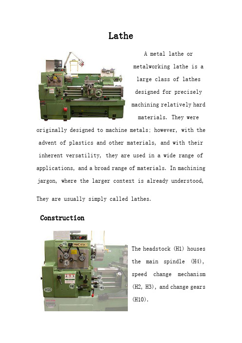
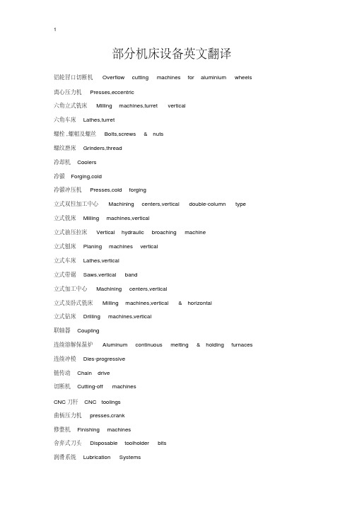
LatheA metal lathe ormetalworking lathe is alarge class of lathesdesigned for preciselymachining relatively hardmaterials. They were originally designed to machine metals; however, with the advent of plastics and other materials, and with their inherent versatility, they are used in a wide range of applications, and a broad range of materials. In machining jargon, where the larger context is already understood, They are usually simply called lathes.ConstructionThe headstock (H1) housesthe main spindle (H4),speed change mechanism(H2, H3), and change gears(H10).The feed screw (H8) is a long driveshaft that allows a series of gears to drive the carriage mechanisms. These gears are located in the apron of the carriage. Both the feedscrew and leadscrew (H7) are driven by either the change gears (on the quadrant) or an intermediate gearbox known as a quick change gearbox (H6) or Norton gearbox. These intermediate gears allow the correct ratio and direction to be set for cutting threads or worm gears. Tumbler gears (operated by H5) are provided between the spindle and gear train along with a quadrant plate that enables a gear train of the correct ratio and direction to be introduced. This provides a constant relationship between the number of turns the spindle makes, to the number of turns the leadscrew makes. This ratio allows screwthreads to be cut on the workpiece without the aid of a die.There are various of lathes within the metalworking field. For example, Center lathe, engine lathe, bench lathe and so on.。
机床设备名称中文英文翻译
部分机床设备英文翻译铝轮冒口切断机 Overflow cutting machines for aluminium wheels 离心压力机 Presses,eccentric六角立式铣床 Milling machines,turret vertical六角车床 Lathes,turret螺栓,螺帽及螺丝 Bolts,screws & nuts螺纹磨床 Grinders,thread冷却机 Coolers冷锻 Forging,cold冷锻冲压机 Presses,cold forging立式双柱加工中心 Machining centers,vertical double-column type 立式铣床 Milling machines,vertical立式油压拉床 Vertical hydraulic broaching machine立式刨床 Planing machines vertical立式车床 Lathes,vertical立式带锯 Saws,vertical band立式加工中心 Machining centers,vertical立式及卧式铣床 Milling machines,vertical & horizontal立式钻床 Drilling machines,vertical联轴器 Coupling连续溶解保温炉 Aluminum continuous melting & holding furnaces 连续冲模 Dies-progressive链传动 Chain drive切断机 Cutting-off machinesCNC刀杆 CNC toolings曲柄压力机 presses,crank修整机 Finishing machines舍弃式刀头 Disposable toolholder bits润滑系统 Lubrication Systems润滑液 Lubricants熔热处理炉 Heating treatment funaces三爪、分割工具头 3-Jaws indexing spacers伺服冲床 Presses,servo输送链 Conveying chains手工具 Hand tools砂轮修整器 Wheel dressers蚀刻机 Etching machines外圆磨床 Grinding machines,cylindrical搪磨机 Honing machines搪孔头 Boring heads卧式铣床 Milling machines,horizontal卧式带锯 Saws,horizontal band卧式加工中心 Machining centers,horizontal卧式及立式加工中心 Machining centers,horizontal & vertical 万能铣床 Milling machines,universal万能磨床 Grinding machines,universal镗床 Boring machines弯曲机 Bending machines弯管机 Tube bending machines通用加工中心 Machining centers,general铜锻 Forging,copper铣头 Milling heads铣床 Milling machines无心磨床 Grinding machines,centerless无心精研机 Lapping machines,centerless压模 Pressing dies压铸冲模 Die casting dies压铸机 Die casting machines油冷却器 Oil coolers。
机床常用翻译
加工中心机刀库 A.T.C.system连续溶解保温炉Aluminum continuous melting & holding furnaces锯片"Blades平衡设备Balancing equipment卡口Bayonet轴承配件Bearing fittings轴承加工机Bearing processing equipment轴承Bearings带传动Belt drive弯曲机Bending machines刀片Blades搪孔头Boring heads镗床Boring machines铸铝"Casting其他铸造"Casting铸铜"Casting铸钢"Casting铸灰口铁"Casting可锻铸铁"Casting造线机Cable making tools造线机Cable making tools链传动Chain drive倒角机Chamfer machines夹盘Chucks夹具/支持系统Clamping/holding systems刀杆CNC toolings CNC立式钻床"Drilling machines 摇臂钻床"Drilling machines多轴钻床"Drilling machines高速钻床"Drilling machines钻石刀具Diamond cutters晶圆切割机Dicing saws压铸冲模Die casting dies压铸机Die casting machines连续冲模Dies-progressive舍弃式刀头Disposable toolholder bits 拔丝机Drawing machines钻床Drilling machines钻床工作激光雕刻机"Engraving machines激光雕刻机"Engraving machines电火花机Electric discharge machines(EDM)电动刀具Electric power tools雕刻机Engraving machines蚀刻机Etching machines钢锻"Forging冷锻"Forging铜锻"Forging其他锻造"Forging锻铝"Forging钢锻"Forging修整机Finishing machines夹具Fixture锻模Forging dies铸造设备Foundry equipment螺纹磨床"Grinders超声波打磨机"Grinders工具磨床"Grinders无心磨床"Grinding machines外圆磨床"Grinding machines万能磨床"Grinding machines齿轮切削机Gear cutting machines齿轮Gears重力铸造机Gravity casting machines 磨床工作台Grinder bench磨床Grinding machines磨削工具Grinding tools磨轮Grinding wheels手工具Hand tools硬(软)板(片)材及自由发泡板机组Hard/soft and free expansion sheet making plant材及自由发泡板机组Hard/soft and free expansion sheet making plant 硬(软)板(片)保温炉Heat preserving furnaces熔热处理炉Heating treatment funaces搪磨机Honing machines液压元件Hydraulic components液压工具Hydraulic power tools液压动力元件Hydraulic power units 液压回转缸Hydraulic rotary cylinders 三爪、分割工具头3-Jaws indexing spacers钻模Jigs 无心精研机"Lapping machines六角车床"Lathes立式车床"Lathes重型车床"Lathes高速车床"Lathes自动车床"Lathes精研机Lapping machines激光切割Laser cutting激光钢板切割机Laser cutting for SMT stensil车床工作台Lathe bench润滑液Lubricants润滑系统Lubrication Systems注油机Lubricators通用加工中心"Machining centers卧式加工中心"Machining centers立式加工中心"Machining centers立式双柱加工中心"Machining centers 卧式及立式加工中心"Machining centers通用加工中心"Machining centers床身式铣床"Milling machines仿形铣床"Milling machines六角立式铣床"Milling machines立式铣床"Milling machines立式及卧式铣床"Milling machines卧式铣床"Milling machines万能铣床"Milling machines床身式铣床"Milling machines仿形铣床"Milling machines磁性工具Magnetic tools集合管Manifolds铣头Milling heads铣床Milling machines模具单元Mold & die components换模系统Mold changing systems模芯Mold core模具加热器/冷却器Mold heaters/chillers模具打磨/磨纹Mold polishing/texturing模具维修Mold repair模具Molds造钉机Nail making machines油冷却器Oil coolersmachines for aluminium wheels铝轮冒口切断机Overflow cutting machines for aluminium wheels立式刨床Planing machines vertical 气油压虎钳Pneumatic hydraulic clamps气动工具Pneumatic power tools粉末冶金成型机Powder metallurgic forming machines压模Pressing dies冲子研磨器Punch formers高分子防水P type PVC waterproof rolled sheet making plant P型PVC速换模系统Quick die change systems 快速换模系统Quick mold change systems反射炉Reverberatory furnaces滚筒Rollers辗压机Rolling machines转台Rotary tables带锯床"Sawing machines卧式带锯"Saws立式带锯"Saws带锯"Saws弓锯"Saws锯床Sawing machines轴shafts牛头刨床Shapers剪切机Shearing machines金属板成型机Sheet metal forming machines金属板成型机Sheet metal forming machines插床Slotting machines主轴spindles冲压机Stamping parts矫直机Straightening machines开关及按钮Switches & buttons攻螺丝机Tapping machines传动链Transmitted chains弯管机Tube bending machines精密平口钳"Vises立式油压拉床Vertical hydraulic broaching machine虎钳Vises砂轮修整器Wheel dressers织麦激光切割机Woven-Cutting machines扳手Wrenches。
车床英语

incorporate [inkɔ:pəreit] v. 包括,合并 matter [mætə] v. 要紧,有重 大关系 tapered [teipəd] a. 锥形的 nose [nəuz] n. 端部,管口 feed [fi:d] n. 进给 lever [li:və] n.杠杆,手柄, 把柄 jaw n. 卡爪,虎钳牙.
二、Text
Tapered centers in the hollow nose of the spindle and of the tailstock hold the work firmly between them. A feed-shaft from the headstock drives the tool-post along the saddle, either forwards or backwards, at a fixed and uniform speed. This enables the operator to make accurate cuts and to give the work a good finish. Gears between the spindle and the feed-shaft control the speed of rotation of the shaft, and therefore the forward or backward movement of the tool-post. The gear which the operator will select depends on the type of metal which he is cutting and the amount of metal he has to cut off.
关于车床的英文作文

关于车床的英文作文英文:Car lathe, also known as turning machine, is a common machine tool in mechanical processing. It is mainly usedfor turning cylindrical, conical and other rotating surfaces, as well as various types of internal and external threads, grooves and cutting work. As a mechanical engineer, I have had the opportunity to use car lathes in my work.The car lathe is a versatile machine tool. It can be used to process various materials, such as metal, plastic, wood, and even some ceramics. The lathe can also perform a variety of operations, including facing, drilling, boring, turning, and threading. One of the advantages of the car lathe is its ability to produce high-precision parts with tight tolerances. This makes it an essential tool in industries such as aerospace, automotive, and medicaldevice manufacturing.When using a car lathe, it is important to followproper safety procedures. The lathe can be dangerous if not used correctly. For example, if the workpiece is notsecured properly, it can fly off the lathe and cause injury. It is also important to wear appropriate personalprotective equipment, such as safety glasses and gloves.In my work, I have used the car lathe to produce a variety of parts. One example is a shaft for a motor. The shaft needed to be precisely machined to fit into the motor housing and rotate smoothly. Using the car lathe, I wasable to turn the shaft to the required diameter and length, and also add keyways for the motor to engage with. The finished shaft fit perfectly into the motor and functioned as intended.Overall, the car lathe is an essential tool in mechanical engineering. Its versatility and precision makeit a valuable asset in many industries. However, it is important to use the lathe safely and follow proper procedures to avoid injury.中文:车床,也称为车削机,在机械加工中是一种常见的机床。
外文翻译-车床和车削
英文材料Lathe and TurningThe Lathe and Its ConstructionA lathe is a machine tool used primarily for producing surfaces of revolution flat edges. Based on their purpose ,construction , number of tools that can simultaneously be mounted , and degree of automation ,lathes or, more accurately, lathe-type machine tools can be classified as follow s:(1) Engine lathes(2) Toolroom lathes(3) Turret lathes(4) Vertical turning and boring mills(5) Automatic lathes(6) Special-purpose lathesIn spite of that diversity of lathe-type machine tools, they all have all have common features with respect to construction and principle of operation .These features can best be illustrated by considering the commonly used representative type, the engine lathe. Following is a description of each of the main elements of an engine lathe , which is shown in Fig.11.1.Lathe bed . The lathe bed is the main frame , involving a horizontal beam on two vertical supporis. It is usually made of grey or nodular cast iron to damp vibrations and is made by casting . It has guideways to allow the carriage to slide easily lengthwise. The height of the lathe bed should be appropriate to enable the technician to do his or her jib easily and comfortably.Headstock. The headstock is fixed at the left hand side of the lathe bed and includes the spindle whose axis is parallel to the guideways (the silde surface of the bed) . The spindle is driven through the gearbox , which is housed within the headstock. The function of the gearbox is to provide a number of different spindle speeds (usually 6 up to 18 speeds) . Some modern lathes have headstocks with infinitely variable spindle speeds, which employ frictional , electrical , or hydraulic drives.The spindle is always hollow , I .e ,it has a through hole extending lengthwise. Bar stocks can be fed througth that hole if continous production is adopted . A lso , that hole has a tapered surface to allow mounting a plain lathe center . The outer surface of the spindle isthreaded to allow mounting of a chuck , a face plate , or the like .Tallstock . The tailstock assembly consists basically of three parts , its lower base, an intermediate part, and the quill . The lower base is a casting that can slide on the lathe bed along the guidewayes , and it has a clamping device to enable locking the entire tailstock at any desired location , depending upon the length of the workpiece . The intermediate parte is a casting that can be moved transversely to enable alignment of the axis of the the tailstock with that of the headstock . The third part, the quill, is a hardened steel tube, which can be moved longitudinally in and out of the intermediate part as required . This is achieved through the use of a handwheel and a screw , around which a nut fixed to the quill is can be locked at any point along its travel path by means of a clamping device.The carriage. The main function of the carriage is mounting of the cutting tools and generating longitudinal and /or cross feeds. It is actually an H-shaped block that slides on the lathe bed between the headstock and tailstock while being guided by the V-shaped guideways of the bed . The carriage can be moved either manually or mechanically by means of the apron and either the feed rod or the lead screw.When cutting screw threads, power is provided to the gearbox of the apron by the lead screw. In all other turning operations, it is the feed rod that drives the carriage. The lead screw goes through a pair o half nuts , which are fixed to the rear of the apron . When actuating a certain lever, the half nuts are clamped together and engage with the rotating lead screw as a single nut, which is fed , together with carriage, along the bed . when the lever is disengaged , the half nuts are released and the carriage stops. On the other hand , when the feed rod is used, it supplies power to the apron through a wrom gear . The latter is keyed to feed rod and travels with the apron along the feed rod , which has a keyway extending to cover its whole length. A modern lathe usually has a quick-change gearbox located under the headstock and driven from the spindle through a train of gears. It is connected to both the feed rod and the lead screw and enables selecting a variety of feeds easily and rapidly by simply shifting the appropriate levers, the quick-change gearbox is employed in plain turning, facing and thread cutting operations. Since that gearbox is linked to spindle, the distance that the apron (and the cutting tool) travels for each revolution of the spindle can be controlled and is referred to as the feed.Lathe Cutting ToolsThe shape and geometry of the lathe tools depend upon the purpose for which they are employed. Turning tools can be classified into tow main groups,namely,external cutting tools and internal cutting tools , Each of these groups include the following types of tools:Turning tools. Turing tools can be either finishing or rough turning tools . Rough turning tools have small nose radii and are used for obtaining the final required dimensions with good surface finish by marking slight depth of cut . Rough turning tools can be right –hand or left-hand types, depending upon the direction of feed. They can have straight, bent, or offset shanks.Facing tools . Facing tools are employed in facing operations for machining plane side or end surfaces. There are tools for machining left-hand-side surfaces and tools for right-hand-side surfaces. Those side surfaces are generated through the use of the cross feed, contrary to turning operations, where the usual longitudinal feed is used.Cutoff tools. Cutoff tools ,which are sometimes called parting tools, serve to separate the workpiece into parts and/or machine external annual grooves.Thread-cutting tools. Thread-cutting tools have either triangular, square, or tranpezoidal cutting edges, depending upon the cross section of the desired thread .Also , the plane angles of these tools must always be identical to those of the thread forms. Thread-cutting tools have straight shanks for external thread cutting and are of the bent-shank type when cutting internal threads .Form tools. Form tools have edges especially manufactured to take a certain form, which is opposite to the desired shape of the machined workpiece . An HSS tools is usually made in the form of a single piece ,contrary to cemented carbides or ceramic , which are made in the form of tipes. The latter are brazed or mechanically fastened to steel shanks. Fig.11.2 indicates an arrangement of this latter type, which includes the carbide tip , the chip breaker ,the pad ,the clamping screw (with a washer and a nut ) , and the shank.. As the name suggests, the function of the chip breaker is to break long chips every now and then , thus preventing the formation of very long twisted ribbons that may cause problems during the machining operations . The carbide tips ( or ceramic tips ) can have different shapes, depending upon the machining operations for which they are to be employed . The tips can either be solid or with a central through hole ,depending on whether brazing or mechanical clamping is employed for mounting the tip on the shank.Lathe OperationsIn the following section , we discuss the various machining operations that can be performed on a conventional engine lathe. It must be borne in mind , however , that modern computerized numerically controlled lathes have more capabiblities and do other operations ,such as contouring , for example . Following are conventional lathe operations.Cylindrical turning . Cylindrical turning is the the simplest and the most common ofall lathe operations . A single full turn of the workpiece generate a circle whose center falls on the lathe axis; this motion is then reproduced numerous times as a result of the axial feed motion of the tool. The resulting machining marks are , therefore ,a helix having a very small pitch, which is equal to the feed . Consequently , the machined surface is always cylindrical.The axial feed is provided by the carriage or the compound rest , either manually or automatically, whereas the depths of cuts is controlled by the cross slide . In roughing cuts , it is recommended that large depths of cuts (up to 0.25 in. or 6 mm, depending upon the workpiece material) and smaller feeds would be used. On the other hand , very fine feeds, smaller depth of cut (less than 0.05in. , or 0.4 mm) , and high cutting speeds are preferred for finishing cuts.Facing . The result of a facing operation is a flat surface that is either the whole end surface of the workpiece or an annular intermediate surface like a shoulder . During a facing operation ,feed is provided by the cross slide, whereas the depth of cut is controlled by the carriage or compound rest . Facing can be carried out either from the periphery in ward or from the center of the workpiece outward . It is obvious that the machining marks in both cases tack the form of a spiral. Usually, it is preferred to clamp the carriage during a facing operation, since the cutting force tends to push the tool ( and , of course , the whole carriage ) away from the workpiece . In most facing operations , the workpiece is held in a chuck or on a face plate.Groove cutting. In cut-off and groove-cutting operations ,only cross feed of the tool is employed. The cut-off and grooving tools , which were previously discussed, are employed.Boring and internal turning . Boring and internal are performed on the internal surfaces by a boring bar or suitable internal workpiece is solid, a drilling operation must be performed first . The drilling tool is held in the tailstock, and latter is then fed against the workpiece.Taper turning . Taper turning is achieved by driving the tool in a direction that is not paralled to the lathe axis but inclined to it with an angle that is equal to the desired angle of the taper . Following are the different methods used in taper-turning practice: Rotating the disc of the compound rest with an angle to half the apex angle of the cone . Feed is manually provided by cranking the handle of the compound rest . This method is recommended for taper turning of external and internal surfaces when the taper angle is relatively large.Employing special form tools for external , very short ,conical surfaces . The width ofthe workpiece must be slightly smaller than that of the tool ,and the workpiece is usually held in a chuck or clamped on a face plate . I n this case , only the cross feed is used during the machining process and the carriage is clamped to the machine bed .Offsetting the tailstock center . This method is employed for esternal tamper turning of long workpiece that are required to have small tamper angles (less than 8 ) . The workpiece is mounted between the two centers ; then the tailstock center is shifted a distance S in the direction normal to the lathe axis.Using the taper-turning attachment . This method is used for turning very long workpoece , when the length is larger than the whole stroke of the compound rest . The procedure followed in such cases involves complete disengagement of the cross slide from the carriage , which is then guided by the taper-turning attachment . During this process, the automatic axial feed can be used as usual . This method is recommend for very long workpiece with a small cone angle , i.e. , 8 through 10 .Thread cutting . When performing thread cutting , the axial feed must be kept at a constant rate , which is dependent upon the rotational speed (rpm) of the workpiece . The relationship between both is determined primarily by the desired pitch of the thread to be cut .As previously mentioned , the axial feed is automatically generated when cutting a thread by means of the lead screw , which drives the carriage . When the lead screw rotates a single revolution, the carriage travels a distance equal to the pitch of the lead screw rotates a single revolutional speed of the lead screw is equal to that of the spindle ( i. e . , that of the workpiece ), the pitch of the resulting cut thread is exactly to that of the lead screw . The pitch of the resulting thread being cut therefore always depends upon the ratio of the rotational speeds of the lead scew and the spindle :Pitch of the lead screw rpm of the workpiece = spindle-to-carriage gearing ratio Desired pitch of workpiece rpm of lead screwThis equation is usefully in determining the kinematic linkage between the lathe spindle and the lead screw and enables proper selection of the gear train between them .n thread cutting operations , the workpiece can either be held in the chuck or mounted between the two lathe centers for relatively long workpiece . The form of the tool used must exactly coincide with the profile the thread to be cut , I . e . , triangular tools must be used for triangular threads , and so on .Knurling . knurling is mainly a forming operation in which no chips are prodyced . Tt involves pressing two hardened rolls with rough filelike surfaces against the rotatingworkpiece to cause plastic deformation of the workpiece metal.Knurling is carried out to produce rough , cylindrical ( or concile )surfaces , which are usually used as handles . Sometimes , surfaces are knurled just for the sake of decoration ; there are different types of patterns of knurls from which to choose .Cutting Speeds and FeedsThe cutting speed , which is usually given in surface feet per minute (SFM), is the number of feet traveled in circumferential direction by a given point on the surface (being cut ) of the workpiece in one minute . The relationship between the surface speed and rpm can be given by the following equation :SMF =3.14*DNWhereD= the diameter of the workpiece in feetN=the rpmThe surface cutting speed is dependent primarily upon the machined as well as the material of the cutting and can be obtained from handbooks , information provided by cutting tool manufacturera , and the like . generally , the SFM is taken as 100 when machining cold-rolled or mild steel ,as 50 when machining tougher metals , and as 200 when machining sofer materials . For aluminum ,the SFMis usually taken as 400 or above . There are also other variables that affect the optimal value of the surface cutting speed . These include the tool geometry, the type of lubricant or coolant , the feed , and the depth of cut . As soon as the cutting sped is decided upon , the rotational speed (rpm) of the spindle can be obtained as follows :SFM =3.14*DThe selection of a suitable feed depends upon many factors , such as the required surface finish , the depth of cut , and the geometry of the tool used . Finer feeds produce better surface finish ,whereas higher feeds reduce the machining time during which the toolis in direct contact with the workpiece . Therefore ,it is generally recommended to use high feeds for roughing operations and finer feeds for finishing operations. Again, recommend values for feeds , which can be taken as guidelines , are found in handbooks and information booklets provided by cutting tool manufacturers.Here I want to introduce the drilling and milling :Drilling involves producing through or blind holes in a workpiece by forcing a tool , which rotates around its axis , against the workpiece .Consequently , the range of cutting from that axis of rotation is equal to the radius of the required hole .In practice , two symmetricalcutting edges that rotate about the same axis are employed .Drilling operations can be carried out by using either hand drills or drilling machines . The latter differ in size and construction . nevertheless , the tool always rotates around its axis while the workpiece is kept firmly fixed . this is contrary to drilling on a lathe .Cutting Tool for Drilling OperationsIn drilling operations , a cylindrical rotary-end cutting , called a drill , is employed . The drill can have either one or more cutting edges and corresponding flutes , which can be straight or helical . the function of the flutes is to provide outlet passages for the chips generated during the drilling operation and to allow lubricants and coolants to reach the cutting edges and the surface being machined . Following is a survey of the commonly used drills.Twist drill . The twist drill is the most common type of drill .It has two cutting edges and two helical flutes that continue over the length of the drill body , as shown in Fig 12.1 The drill also consist of a neck and a shake that can be either straight or tapered .In the latter case , the shank is fitted by the wedge action into the tapered socket of the spindle and has a tang , which goes into a slot in the spindle socket ,thus acting as a solid means for transmitting rotation . On the other hand , straight –shank drills are held in a drill chuck that is , in turn , fitted into the spindle socket in the same way as tapered shank drills.As can be seen in FIG.12.1 , the two cutting edges are referred to as the lips , and are connected together by a wedge , which is a chisel-like edge . The twist drill also has two margins , which enable proper guidance and locating of the drill while it is in operation . The tool point angle (TPA) is formed by the lips and is chosen based on the properties of the material to be cut . The usual TAP for commercial drills is 118 , which is appropriate for drilling low-carbon steels and cast irons . For harder and tougher metals , such as hardened steel , brasss and bronze , larger TPAs (130 OR 140 ) give better performance . The helix angle of the flutes of the commonly used twist drills ranges between 24 and 30 . When drilling copper or soft plastics , higher values for the helix angle are recommended (between 35 and 45).Twist drills are usually made of high speed steel ,although carbide tipped drills are also available . The size of twist drills used in industrial range from 0.01 up to 3.25 in . (i.e.0.25 up to 80 mm ) .Core drills . A core drill consists of the chamfer , body , neck ,and shank , as shown in Fig 12.2 . This type of drill may be have either three or four flutes and an equal number of margins , which ensure superior guidance , thus resulting in high machining accuracy . It can also be seen in Fig 12.2 that a core drill has flat end . The chamfer can have three or four cuttingedges or lips , and the lip angle may vary between 90 and 120 . Core drills are employed for enlarging previously made holes and not for originating holes . This type of drill is characterized by greater productivity , high machining accuracy , and superior quality of the drilled surfaces .Gun drills . Gun drills are used for drilling deep holes . All gun drills are straight fluted , and each has a single cutting edge . A hole in the body acts as a conduit to transmit coolant under considerable pressure to the tip of the drill .There are two kinds of gun drills , namely , the center cut gun drill used for drilling blind holes and the trepanning drill . The latter has a cylindrical groove at its center , thus generating a solid core , which guides the tool as it proceeds during the drilling operation.Spade drills . Spade drills are used for drilling large holes of 3.5 in .(90 mm ) or more . Their design results in a marked saving in cost of the tool as well as a tangible reduction in its weight , which facilitates its handling . moreover , this type of drill is easy to be ground .Milling and Milling CuttersMilling is a machining process that is carried out by means of a multiedge rotating tool known as a milling cutter . In this process ,metal removal is achieved through combining the rotary motion of the milling cutter and linear motions of the workpiece simultaneously . Milling operations are employed in producing flat , contoured and helical surfaces as well as for thread and gear and gear cutting operations.Each of the cutting edges of a milling cuter acts as an individual single point cutter when it engages with the workpiece metal . therefore , each of those cutting edges has the workpiece at a time ,heavy cuts can be taken without adversely affecting the tool life .In fact ,the permissible cutting speeds and feeds for milling are there to four times higher than those for turning or drilling .Moreover ,the quality of the surfaces machined by milling is generally superior of surfaces machined by turning shaping ,or drilling.A wide variety of milling cutters is available in industry .This, together with the fact that a milling machine is very versatile machine tool ,makes the milling machine the backbone of a machining workshop .As far as the direction of cutter rotation and workpiece feed are concerned , milling is performed by either of the following tow methods .Up milling (conventional milling). In up milling workpiece is fed against the direction of cutter rotation, as shown in Fig.12.3. As we can see in that figure ,the depth of cut (and consequently the load ) gradually increases on the successively engaged cutting edges . Therefore, the machining process involves no impact loading , thus ensuring smother operationof the machine tool and longer tool life .The quality of the machined surface obtained by up milling is not very high . Nevertheless , up milling is commonly used in industry , especially for rough cuts.Down milling (climb milling ). Ascan be seen in Fig 12.3, in down milling the cutter rotation coincides with the direction of feed at the contact point between the tool and the workpiece . It can also be seen that the maximum depts. Of cut is achieved directly as the cutter engages with the workpiece . This results in a kind of impact , or sudden loading . Therefore, this method cannot be used the milling machine is equipped with a backlash elimination on the feed screw . The advantages of this method include higher quality of machined surface and easier clamping of workpieces, since the cutting forces act downward .Types of Milling CuttersThere is a wide variety of milling cutter shapes .Each of them is designed to perform effectively a specific milling operations . Generally ,a milling cutter can be described as a multiedge cutting tool having the shape of a solid of revolution ,with the cutting teeth arranged either on the periphery or on an end face or on both . Following is a quick survery of the commonly used types of milling cutters.Plain milling cutter . a plain milling cutter is a disk – shaped cutting tool that may have either straight or helical teeth ,as shown in Fig .12.4 .This type is always mounted on horizontal milling machines and is used for maching flat surfaces.Face milling cutter . A face milling cutter is also used for maching flat surfaces. It is bolted at the end of a short arbor ., which is in turn mounted on a vertical milling machine . Fig 12.4 indicates a milling cuter of this type.Plain metal slitting saw cutter .Fig 12.4 indicates a plain metal slitting saw cutter . We can see that it actually involves a very thin plain milling cutter.Side milling cutter. A side milling cutter is used for cutting solts, grooves, and splines. As shown in Fig 12.4 ,it is quite similar to the plain milling cutter , the difference being that this type has teeth on the sides .As is the case wih the plain cutter , the cutting teeth can be straight or helical .Angle milling cutter . Angle milling cutter is employed in cutting dovetail grooves , ratchet wheels, and the like .Fig 12.4 indicates a milling cutter of this type.T slot cutter . As shown in Fig 12.4 ,a T slot cutter involves a plain milling cutter with an integral shaft normal to it .As the name suggests ,this type is used for milling T slots.End mill cutter . End mill cutters find common applications in cutting slots , grooves , flutes , splines ,pocketing work, and the like . Fig 12.4 indicates an end mill cutter . The latteris always mounted on a vertical milling machine and can have toe or four flutes , which may be either straight or helical .Form milling cutter . The teeth of a form milling cutter have a certain shape , which is identical to the section of the metal to be removed during the milling operation. Examples of this type include gear cutters ,gear hobs, convex and concave cutters ,and the like . Form milling cutters are mounted on horizontal milling machines.Materialas of Milling CuttersThe commonly used milling cutters are made of high speed steel , which is generally adequate for most jobs . Milling cutters tipped with sintered carbides or cast nonferrous alloys as cutting teeth are usually employed for mass production , where heavier cuts and / or high cutting speeds are required.Here I want to introduce the MaterialsTypes of MaterialsMaterials may be grouped in several ways . scientists often classify materials by their state : solid , liquid , or gas . They also separate them into organic (once living) and inorganic (never living) materials.For industrial purposes , materials are divided into engineering materials or nonengineering materials .Engineering materials are those used in manufacture and become parts of products . Nonengineering materials are the chemicals ,fuels , lubricants ,and other materials used in the manufacturing process, which do not become part of the product.Engineering materials may be further subdivided into : 1 , Metals 2, Ceramics 3, Composite 4, Polymers , etc .Metals and Metals AlloysMetals are elements that generally have good electrical and thermal conductivity . Many metals have high strength , high stiffness , and have good ductility . Some metals ,such as iron ,cobalt and nickel , are magnetic . At extremely low temperatures , some metals and intermetallic compounds become superconductors.What is the difference between an alloy and a pure metal ? Pure metals are elements which come from a particular area of the periodic table . Examples of pure metals include copper in electrical wires and aluminum in cooking foil and beverage cans. Alloys contain more than one metallic element . Their properties can be changed by changing the elements present in the alloy . Examples of metal alloys include stainless steel which is an alloy of iron ,nickel ,and gold jewelry which usually contains an alloy of gold and nickel.Why are metals and alloys used ? Many metals have high densities and used inapplications which require a high mass to volume ratio. Some metal alloys , such as those based on aluminum , have low densities and are used in aerospace applications for fuel economy. Many alloys also have high fracture toughness, which means they can withstand impact and are durable.What are some important properties of metals?Density is defined as a material is a mass divided by its volume . Most metals have relatively high densities ,especially compared to polymers . Materials with high densities often contain atoms with high atomic numbers , such as gold or lead . However, some metals such as aluminum or magnesium have low densities ,and are used in applications that require other metallic proerties but also require low weight.Fracture toughness can be described as a material‘s ability to avoid fracture, especially when a flaw is introduced .Metals can generally contain nicks and dents without weakening very much ,and are impact resistant .A football player counts on this when he trusts that his facemask won’t shatter.Plastic deformation is the ability of a material to bend or deform before breaking .As engineers , we usuall y design materials so that don’t deform under normal conditions . You don’t want you car to lean to the east after a strong west wind .However ,sometimes we can take advantage of plastic deformation. The crumple zones in a car absorb energy by undergoing plastic deformation before pass through.Alloy are compounds consisting of more than one metal one metal .Adding other metals can affect the density ,strength , fracture toughness , plastic deformation, electrical conductivity and environmental degradation .For example ,adding a small smount of iron to aluminum will make it stronger .Also , adding some chromium to steel will slow the rusting process, but will make it more brittle.。
部分机床设备英文翻译
部分机床设备英文翻译铝轮冒口切断机 Overflow cutting machines for aluminium wheels 离心压力机 Presses,eccentric六角立式铣床 Milling machines,turret vertical六角车床 Lathes,turret螺栓,螺帽及螺丝 Bolts,screws & nuts螺纹磨床 Grinders,thread冷却机 Coolers冷锻 Forging,cold冷锻冲压机 Presses,cold forging立式双柱加工中心 Machining centers,vertical double-column type立式铣床 Milling machines,vertical立式油压拉床 Vertical hydraulic broaching machine立式刨床 Planing machines vertical立式车床 Lathes,vertical立式带锯 Saws,vertical band立式加工中心 Machining centers,vertical立式及卧式铣床 Milling machines,vertical & horizontal立式钻床 Drilling machines,vertical联轴器 Coupling连续溶解保温炉 Aluminum continuous melting & holding furnaces 连续冲模 Dies-progressive链传动 Chain drive切断机 Cutting-off machinesCNC刀杆 CNC toolings曲柄压力机 presses,crank修整机 Finishing machines舍弃式刀头 Disposable toolholder bits润滑系统 Lubrication Systems润滑液 Lubricants熔热处理炉 Heating treatment funaces三爪、分割工具头 3-Jaws indexing spacers伺服冲床 Presses,servo输送链 Conveying chains手工具 Hand tools砂轮修整器 Wheel dressers蚀刻机 Etching machines外圆磨床 Grinding machines,cylindrical搪磨机 Honing machines搪孔头 Boring heads卧式铣床 Milling machines,horizontal卧式带锯 Saws,horizontal band卧式加工中心 Machining centers,horizontal卧式及立式加工中心 Machining centers,horizontal & vertical 万能铣床 Milling machines,universal万能磨床 Grinding machines,universal镗床 Boring machines弯曲机 Bending machines弯管机 Tube bending machines通用加工中心 Machining centers,general铜锻 Forging,copper铣头 Milling heads铣床 Milling machines无心磨床 Grinding machines,centerless无心精研机 Lapping machines,centerless压模 Pressing dies压铸冲模 Die casting dies压铸机 Die casting machines油冷却器 Oil coolers造链机 Chain making tools造线机 Cable making tools造钉机 Nail making machines印刷电器板油压冲孔脱料系统 PCB fine piecing systems摇臂钻床 Drilling machines,radial硬(软)板(片)材及自由发泡板机组 Hard/soft and free expansion sheet making plant 辗压机 Rolling machines液压元件 Hydraulic components液压冲床 Presses,hydraulic液压动力元件 Hydraulic power units液压工具 Hydraulic power tools液压回转缸 Hydraulic rotary cylindersP型PVC高分子防水 P type PVC waterproof rolled sheet making plant刨床 Planing machines牛头刨床 Shapers其他铸造 Casting,other其他锻造 Forging,other模芯 Mold core模具 Molds模具维修 Mold repair模具打磨/磨纹 Mold polishing/texturing模具单元 Mold & die components模具加热器/冷却器 Mold heaters/chillers磨轮 Grinding wheels磨削工具 Grinding tools磨床 Grinding machines磨床工作台 Grinder bench平衡设备 Balancing equipment气油压虎钳 Pneumatic hydraulic clamps气动冲床 Presses,pneumatic气动工具 Pneumatic power tools轴 shafts轴承 Bearings轴承配件 Bearing fittings轴承加工机 Bearing processing equipment 肘杆式压力机 Presses,knuckle joint铸铝 Casting,aluminium铸铜 Casting,copper铸造设备 Foundry equipment铸钢 Casting,steel铸灰口铁 Casting,gray iron织麦激光切割机 Woven-Cutting machines 重力铸造机 Gravity casting machines重型车床 Lathes,heavy-duty主轴 spindles扳手 Wrenches拔丝机 Drawing machines保温炉 Heat preserving furnaces插床 Slotting machines齿轮 Gears齿轮切削机 Gear cutting machines冲压机 Stamping parts冲子研磨器 Punch formers超声波打磨机 Grinders,ultrasonic车床工作台 Lathe bench磁性工具 Magnetic tools传动链 Transmitted chains床身式铣床 Milling machines,bed type带传动 Belt drive带锯 Saws,band带锯床 Sawing machines,band电脑数控镗床 CNC boring machines电脑数控弯折机 CNC bending presses电脑数控铣床 CNC milling machines电脑数控线切削机 CNC wire-cutting machines电脑数控磨床 CNC grinding machines电脑数控车床 CNC lathes电脑数控电火花线切削机 CNC EDM wire-cutting machines 电脑数控电火花机 CNC electric discharge machines电脑数控雕刻机 CNC engraving machines电脑数控机床配件 CNC machine tool fittings电脑数控剪切机 CNC shearing machines电脑数控钻床 CNC drilling machines电动刀具 Electric power tools电火花机 Electric discharge machines(EDM)雕刻机 Engraving machines刀片 Blades刀具 Cutters倒角机 Chamfer machines多轴钻床 Drilling machines,multi-spindle锻铝 Forging,aluminium锻压机 Presses,forging锻模 Forging dies仿形铣床 Milling machines,duplicating粉末冶金成型机 Powder metallurgic forming machines反射炉 Reverberatory furnaces钢锻 Forging,steel高速车床 Lathes,high-speed高速钻床 Drilling machines,high-speed管筒制造机 Pipe & tube making machines滚筒 Rollers工具磨床 Grinders,tools & cutters攻螺丝机 Tapping machines弓锯 Saws,hack虎钳 Vises换模系统 Mold changing systems夹盘 Chucks夹具 Fixture夹具/支持系统 Clamping/holding systems剪切机 Shearing machines加工中心机刀库 A.T.C.system激光切割 Laser cutting激光雕刻机 Engraving machines,laser激光钢板切割机 Laser cutting for SMT stensil 集合管 Manifolds矫直机 Straightening machines金属板成型机 Sheet metal forming machines 金属板加工机 Sheet metal working machines 锯片 Blades,saw锯床 Sawing machines卷边工具 Crimping tools晶圆切割机 Dicing saws精密平口钳 Vises,tool-maker精研机 Lapping machines可锻铸铁 Casting,malleable iron快速换模系统 Quick mold change systems卡口 Bayonet开关及按钮 Switches & buttons钻石刀具 Diamond cutters钻头 drills钻模 Jigs钻床 Drilling machines钻床工作台 Drilling machines bench 自动压力机 Presses,transfer自动车床 Lathes,automatic注油机 Lubricators转台 Rotary tables。
车床专业英语翻译
·特殊的仿形切刀(没有在图示中)能更好的加工铝,加工时把刀刃调整至略高于中
心可减少振动。
安装切削刀具
车刀被安装在刀架上。为了安装刀具,首先要清理刀架,然后拧紧螺栓。
刀杆通过T形螺栓安装在小拖板上,利用快速夹紧手柄将刀杆夹紧在刀架上。
刀具定位
为了移动切削刀具,可用手移动车床的大拖板和横拖板。
通过不断地调整进给量以达到所要求的加工精度。对于切削深度,记住每进给千分之一的切
削深度,工件直径要减少千分之二。
车削
车床用来将工件的直径车到所要求的尺寸。首先,把工件安全地夹紧在卡盘上,工件外
伸的部分不能超过它直径的三倍;然后安装粗加工刀具或者是精加工刀具(选合适的)。如
果你要向主轴箱方向进给大拖板(像在下面剪辑中一样),就用右手车刀。用溜板上的手轮
镗孔
镗孔是用单刃刀具将原有孔扩大的一种加工,它用镗杆支撑刀具深入孔中加工。由于镗
杆是悬伸的,刀具的刚性低,因而容易产生振动。对于这样的情况,可以通过降低主轴转速
或者是把刀尖磨成更小圆弧来消除。
单头螺纹车削
外螺纹可用板牙加工,而内螺纹可用丝锥加工。但是对于某些直径的螺纹,没有合适的
丝锥和板牙,在这种情况下,可以用车床来车螺纹,最典型的是用刀尖角为60度的车刀。
材料去除率。选择进给量和速度的主要因素是被加工材料。当然也要考虑到切削刀具的材料、
加工件的刚度、机床的型号大小、工作条件和切削深度。对大多数铝合金来说,粗加工(切
削深度在0.010到0.020英寸)的速度一般在600英尺/分钟,精加工(切削深度在0.002到
0.010)的速度一般在1000英尺/分钟。用切削速度除以工件的周长就可得到合适的主轴转速。
机械外文翻译中英文_机床

英文原文Basic Machining Operations and Cutting TechnologyBasic Machining OperationsMachine tools have evolved from the early foot-powered lathes of the Egyptians and John Wilkinson's boring mill. They are designed to provide rigid support for both the workpiece and the cutting tool and can precisely control their relative positions and the velocity of the tool with respect to the workpiece. Basically, in metal cutting, a sharpened wedge-shaped tool removes a rather narrow strip of metal from the surface of a ductile workpiece in the form of a severely deformed chip. The chip is a waste product that is considerably shorter than the workpiece from which it came but with a corresponding increase in thickness of the uncut chip. The geometrical shape of workpiece depends on the shape of the tool and its path during the machining operation.Most machining operations produce parts of differing geometry. If a rough cylindrical workpiece revolves about a central axis and the tool penetrates beneath its surface and travels parallel to the center of rotation, a surface of revolution is produced, and the operation is called turning. If a hollow tube is machined on the inside in a similar manner, the operation is called boring. Producing an external conical surface uniformly varying diameter is called taper turning, if the tool point travels in a path of varying radius, a contoured surface like that of a bowling pin can be produced; or, if the piece is short enough and the support is sufficiently rigid, a contoured surface could be produced by feeding a shaped tool normal to the axis of rotation. Short tapered or cylindrical surfaces could also be contour formed.Flat or plane surfaces are frequently required. They can be generated by radial turning or facing, in which the tool point moves normal to the axis of rotation. In other cases, it is more convenient to hold the workpiece steady and reciprocate the tool across it in a series of straight-line cuts with a crosswise feed increment before each cutting stroke. This operation is called planning and is carried out on a shaper. For larger pieces it is easier to keep the tool stationary and draw the workpiece under it as in planning. The tool is fed at each reciprocation. Contoured surfaces can be produced by using shaped tools.Multiple-edged tools can also be used. Drilling uses a twin-edged fluted tool for holes with depths up to 5 to 10 times the drill diameter. Whether thedrill turns or the workpiece rotates, relative motion between the cutting edge and the workpiece is the important factor. In milling operations a rotary cutter with a number of cutting edges engages the workpiece. Which moves slowly with respect to the cutter. Plane or contoured surfaces may be produced, depending on the geometry of the cutter and the type of feed.Horizontal or vertical axes of rotation may be used, and the feed of the workpiece may be in any of the three coordinate directions.Basic Machine ToolsMachine tools are used to produce a part of a specified geometrical shape and precise I size by removing metal from a ductile material in the form of chips. The latter are a waste product and vary from long continuous ribbons of a ductile material such as steel, which are undesirable from a disposal point of view, to easily handled well-broken chips resulting from cast iron. Machine tools perform five basic metal-removal processes: I turning, planning, drilling, milling, and grinding. All other metal-removal processes are modifications of these five basic processes. For example, boring is internal turning; reaming, tapping, and counter boring modify drilled holes and are related to drilling; bobbing and gear cutting are fundamentally milling operations; hack sawing and broaching are a form of planning and honing; lapping, super finishing. Polishing and buffing are variants of grinding or abrasive removal operations. Therefore, there are only four types of basic machine tools, which use cutting tools of specific controllable geometry: 1. lathes, 2. planers, 3. drilling machines, and 4. milling machines. The grinding process forms chips, but the geometry of the abrasive grain is uncontrollable.The amount and rate of material removed by the various machining processes may be I large, as in heavy turning operations, or extremely small, as in lapping or super finishing operations where only the high spots of a surface are removed.A machine tool performs three major functions: 1. it rigidly supports the workpiece or its holder and the cutting tool; 2. it provides relative motion between the workpiece and the cutting tool; 3. it provides a range of feeds and speeds usually ranging from 4 to 32 choices in each case.Speed and Feeds in MachiningSpeeds, feeds, and depth of cut are the three major variables for economical machining. Other variables are the work and tool materials, coolant and geometry of the cutting tool. The rate of metal removal and power required for machining depend upon these variables.The depth of cut, feed, and cutting speed are machine settings that must be established in any metal-cutting operation. They all affect the forces, the power, and the rate of metal removal. They can be defined by comparing them to the needle and record of a phonograph. The cutting speed (V) is represented by the velocity of- the record surface relative to the needle in the tone arm at any instant. Feed is represented by the advance of the needle radially inward per revolution, or is the difference in position between two adjacent grooves. The depth of cut is the penetration of the needle into the record or the depth of the grooves.Turning on Lathe CentersThe basic operations performed on an engine lathe are illustrated. Those operations performed on external surfaces with a single point cutting tool are called turning. Except for drilling, reaming, and lapping, the operations on internal surfaces are also performed by a single point cutting tool.All machining operations, including turning and boring, can be classified as roughing, finishing, or semi-finishing. The objective of a roughing operation is to remove the bulk of the material as rapidly and as efficiently as possible, while leaving a small amount of material on the work-piece for the finishing operation. Finishing operations are performed to obtain the final size, shape, and surface finish on the workpiece. Sometimes a semi-finishing operation will precede the finishing operation to leave a small predetermined and uniform amount of stock on the work-piece to be removed by the finishing operation.Generally, longer workpieces are turned while supported on one or two lathe centers. Cone shaped holes, called center holes, which fit the lathe centers are drilled in the ends of the workpiece-usually along the axis of the cylindrical part. The end of the workpiece adjacent to the tailstock is always supported by a tailstock center, while the end near the headstock may be supported by a headstock center or held in a chuck. The headstock end of the workpiece may be held in a four-jaw chuck, or in a type chuck. This method holds the workpiece firmly and transfers the power to the workpiece smoothly; the additional support to the workpiece provided by the chuck lessens the tendency for chatter to occur when cutting. Precise results can be obtained with this method if care is taken to hold the workpiece accurately in the chuck.Very precise results can be obtained by supporting the workpiece between two centers. A lathe dog is clamped to the workpiece; together they are driven by a driver plate mounted on the spindle nose. One end of the Workpiece is mecained;then the workpiece can be turned around in the lathe to machine the other end. The center holes in the workpiece serve as precise locating surfaces as well as bearing surfaces to carry the weight of the workpiece and to resist the cutting forces. After the workpiece has been removed from the lathe for any reason, the center holes will accurately align the workpiece back in the lathe or in another lathe, or in a cylindrical grinding machine. The workpiece must never be held at the headstock end by both a chuck and a lathe center. While at first thought this seems like a quick method of aligning the workpiece in the chuck, this must not be done because it is not possible to press evenly with the jaws against the workpiece while it is also supported by the center. The alignment provided by the center will not be maintained and the pressure of the jaws may damage the center hole, the lathe center, and perhaps even the lathe spindle. Compensating or floating jaw chucks used almost exclusively on high production work provide an exception to the statements made above. These chucks arereally work drivers and cannot be used for the same purpose as ordinary three or four-jaw chucks.While very large diameter workpieces are sometimes mounted on two centers, they are preferably held at the headstock end by faceplate jaws to obtain the smooth power transmission; moreover, large lathe dogs that are adequate to transmit the power not generally available, although they can be made as a special. Faceplate jaws are like chuck jaws except that they are mounted on a faceplate, which has less overhang from the spindle bearings than a large chuck would have.Introduction of MachiningMachining as a shape-producing method is the most universally used and the most important of all manufacturing processes. Machining is a shape-producing process in which a power-driven device causes material to be removed in chip form. Most machining is done with equipment that supports both the work piece and cutting tool although in some cases portable equipment is used with unsupported workpiece.Low setup cost for small Quantities. Machining has two applications in manufacturing. For casting, forging, and press working, each specific shape to be produced, even one part, nearly always has a high tooling cost. The shapes that may he produced by welding depend to a large degree on the shapes of raw material that are available. By making use of generally high cost equipment but without special tooling, it is possible, by machining; to start with nearly any form of raw material, so tong as the exterior dimensions are great enough, and produce any desired shape from any material. Therefore .machining is usually the preferred method for producing one or a few parts, even when the design of the part would logically lead to casting, forging or press working if a high quantity were to be produced.Close accuracies, good finishes. The second application for machining is based on the high accuracies and surface finishes possible. Many of the parts machined in low quantities would be produced with lower but acceptable tolerances if produced in high quantities by some other process. On the other hand, many parts are given their general shapes by some high quantity deformation process and machined only on selected surfaces where high accuracies are needed. Internal threads, for example, are seldom produced by any means other than machining and small holes in press worked parts may be machined following the press working operations.Primary Cutting ParametersThe basic tool-work relationship in cutting is adequately described by means of four factors: tool geometry, cutting speed, feed, and depth of cut.The cutting tool must be made of an appropriate material; it must be strong, tough, hard, and wear resistant. The tool s geometry characterized by planes and angles, must be correct foreach cutting operation. Cutting speed is the rate at which the work surface passes by the cutting edge. It may be expressed in feet per minute.For efficient machining the cutting speed must be of a magnitude appropriate to the particular work-tool combination. In general, the harder the work material, the slower the speed.Feed is the rate at which the cutting tool advances into the workpiece. "Where the workpiece or the tool rotates, feed is measured in inches per revolution. When the tool or the work reciprocates, feed is measured in inches per stroke, Generally, feed varies inversely with cutting speed for otherwise similar conditions.The depth of cut, measured inches is the distance the tool is set into the work. It is the width of the chip in turning or the thickness of the chip in a rectilinear cut. In roughing operations, the depth of cut can be larger than for finishing operations.The Effect of Changes in Cutting Parameters on Cutting TemperaturesIn metal cutting operations heat is generated in the primary and secondary deformation zones and these results in a complex temperature distribution throughout the tool, workpiece and chip. A typical set of isotherms is shown in figure where it can be seen that, as could be expected, there is a very large temperature gradient throughout the width of the chip as the workpiece material is sheared in primary deformation and there is a further large temperature in the chip adjacent to the face as the chip is sheared in secondary deformation. This leads to a maximum cutting temperature a short distance up the face from the cutting edge and a small distance into the chip.Since virtually all the work done in metal cutting is converted into heat, it could be expected that factors which increase the power consumed per unit volume of metal removed will increase the cutting temperature. Thus an increase in the rake angle, all other parameters remaining constant, will reduce the power per unit volume of metal removed and the cutting temperatures will reduce. When considering increase in unreformed chip thickness and cutting speed the situation is more complex. An increase in undeformed chip thickness tends to be a scale effect where the amounts of heat which pass to the workpiece, the tool and chip remain in fixed proportions and the changes in cutting temperature tend to be small. Increase in cutting speed; however, reduce the amount of heat which passes into the workpiece and this increase the temperature rise of the chip m primary deformation. Further, the secondary deformation zone tends to be smaller and this has the effect of increasing the temperatures in this zone. Other changes in cutting parameters have virtually no effect on the power consumed per unit volume of metal removed and consequently have virtually no effect on the cutting temperatures. Since it has been shown that even small changes in cutting temperature have a significant effect on tool wear rate it is appropriate to indicate how cutting temperatures can be assessed from cutting data.The most direct and accurate method for measuring temperatures in high -speed-steel cutting tools is that of Wright &. Trent which also yields detailed information on temperature distributions in high-speed-steel cutting tools. The technique is based on the metallographic examination of sectioned high-speed-steel tools which relates microstructure changes to thermal history.Trent has described measurements of cutting temperatures and temperature distributions for high-speed-steel tools when machining a wide range of workpiece materials. This technique has been further developed by using scanning electron microscopy to study fine-scale microstructure changes arising from over tempering of the tempered martens tic matrix of various high-speed-steels. This technique has also been used to study temperature distributions in both high-speed -steel single point turning tools and twist drills.Wears of Cutting ToolDiscounting brittle fracture and edge chipping, which have already been dealt with, tool wear is basically of three types. Flank wear, crater wear, and notch wear. Flank wear occurs on both the major and the minor cutting edges. On the major cutting edge, which is responsible for bulk metal removal, these results in increased cutting forces and higher temperatures which if left unchecked can lead to vibration of the tool and workpiece and a condition where efficient cutting can no longer take place. On the minor cutting edge, which determines workpiece size and surface finish, flank wear can result in an oversized product which has poor surface finish. Under most practical cutting conditions, the tool will fail due to major flank wear before the minor flank wear is sufficiently large to result in the manufacture of an unacceptable component.Because of the stress distribution on the tool face, the frictional stress in the region of sliding contact between the chip and the face is at a maximum at the start of the sliding contact region and is zero at the end. Thus abrasive wear takes place in this region with more wear taking place adjacent to the seizure region than adjacent to the point at which the chip loses contact with the face. This result in localized pitting of the tool face some distance up the face which is usually referred to as catering and which normally has a section in the form of a circular arc. In many respects and for practical cutting conditions, crater wear is a less severe form of wear than flank wear and consequently flank wear is a more common tool failure criterion. However, since various authors have shown that the temperature on the face increases more rapidly with increasing cutting speed than the temperature on the flank, and since the rate of wear of any type is significantly affected by changes in temperature, crater wear usually occurs at high cutting speeds.At the end of the major flank wear land where the tool is in contact with the uncut workpiece surface it is common for the flank wear to be more pronounced than along the rest ofthe wear land. This is because of localised effects such as a hardened layer on the uncut surface caused by work hardening introduced by a previous cut, an oxide scale, and localised high temperatures resulting from the edge effect. This localised wear is usually referred to as notch wear and occasionally is very severe. Although the presence of the notch will not significantly affect the cutting properties of the tool, the notch is often relatively deep and if cutting were to continue there would be a good chance that the tool would fracture.If any form of progressive wear allowed to continue, dramatically and the tool would fail catastrophically, i. e. the tool would be no longer capable of cutting and, at best, the workpiece would be scrapped whilst, at worst, damage could be caused to the machine tool. For carbide cutting tools and for all types of wear, the tool is said to have reached the end of its useful life long before the onset of catastrophic failure. For high-speed-steel cutting tools, however, where the wear tends to be non-uniform it has been found that the most meaningful and reproducible results can be obtained when the wear is allowed to continue to the onset of catastrophic failure even though, of course, in practice a cutting time far less than that to failure would be used. The onset of catastrophic failure is characterized by one of several phenomena, the most common being a sudden increase in cutting force, the presence of burnished rings on the workpiece, and a significant increase in the noise level.Mechanism of Surface Finish ProductionThere are basically five mechanisms which contribute to the production of a surface which have been machined. These are:(l) The basic geometry of the cutting process. In, for example, single point turning the tool will advance a constant distance axially per revolution of the workpiecc and the resultant surface will have on it, when viewed perpendicularly to the direction of tool feed motion, a series of cusps which will have a basic form which replicates the shape of the tool in cut.(2) The efficiency of the cutting operation. It has already been mentioned that cutting with unstable built-up-edges will produce a surface which contains hard built-up-edge fragments which will result in a degradation of the surface finish. It can also be demonstrated that cutting under adverse conditions such as apply when using large feeds small rake angles and low cutting speeds, besides producing conditions which lead to unstable built-up-edge production, the cutting process itself can become unstable and instead of continuous shear occurring in the shear zone, tearing takes place, discontinuous chips of uneven thickness are produced, and the resultant surface is poor. This situation is particularly noticeable when machining very ductile materials such as copper and aluminum.(3) The stability of the machine tool. Under some combinations of cutting conditions; workpiece size, method of clamping ,and cutting tool rigidity relative to the machine toolstructure, instability can be set up in the tool which causes it to vibrate. Under some conditions this vibration will reach and maintain steady amplitude whilst under other conditions the vibration will built up and unless cutting is stopped considerable damage to both the cutting tool and workpiece may occur. This phenomenon is known as chatter and in axial turning is characterized by long pitch helical bands on the workpiece surface and short pitch undulations on the transient machined surface.(4)The effectiveness of removing swarf. In discontinuous chip production machining, such as milling or turning of brittle materials, it is expected that the chip (swarf) will leave the cutting zone either under gravity or with the assistance of a jet of cutting fluid and that they will not influence the cut surface in any way. However, when continuous chip production is evident, unless steps are taken to control the swarf it is likely that it will impinge on the cut surface and mark it. Inevitably, this marking besides looking.(5)The effective clearance angle on the cutting tool. For certain geometries of minor cutting edge relief and clearance angles it is possible to cut on the major cutting edge and burnish on the minor cutting edge. This can produce a good surface finish but, of course, it is strictly a combination of metal cutting and metal forming and is not to be recommended as a practical cutting method. However, due to cutting tool wear, these conditions occasionally arise and lead to a marked change in the surface characteristics.Limits and TolerancesMachine parts are manufactured so they are interchangeable. In other words, each part of a machine or mechanism is made to a certain size and shape so will fit into any other machine or mechanism of the same type. To make the part interchangeable, each individual part must be made to a size that will fit the mating part in the correct way. It is not only impossible, but also impractical to make many parts to an exact size. This is because machines are not perfect, and the tools become worn. A slight variation from the exact size is always allowed. The amount of this variation depends on the kind of part being manufactured. For examples part might be made 6 in. long with a variation allowed of 0.003 (three-thousandths) in. above and below this size. Therefore, the part could be 5.997 to 6.003 in. and still be the correct size. These are known as the limits. The difference between upper and lower limits is called the tolerance.A tolerance is the total permissible variation in the size of a part.The basic size is that size from which limits of size arc derived by the application of allowances and tolerances.Sometimes the limit is allowed in only one direction. This is known as unilateral tolerance.Unilateral tolerancing is a system of dimensioning where the tolerance (that is variation) is shown in only one direction from the nominal size. Unilateral tolerancing allow the changing of tolerance on a hole or shaft without seriously affecting the fit.When the tolerance is in both directions from the basic size it is known as a bilateral tolerance (plus and minus).Bilateral tolerancing is a system of dimensioning where the tolerance (that is variation) is split and is shown on either side of the nominal size. Limit dimensioning is a system of dimensioning where only the maximum and minimum dimensions arc shown. Thus, the tolerance is the difference between these two dimensions.Surface Finishing and Dimensional ControlProducts that have been completed to their proper shape and size frequently require some type of surface finishing to enable them to satisfactorily fulfill their function. In some cases, it is necessary to improve the physical properties of the surface material for resistance to penetration or abrasion. In many manufacturing processes, the product surface is left with dirt .chips, grease, or other harmful material upon it. Assemblies that are made of different materials, or from the same materials processed in different manners, may require some special surface treatment to provide uniformity of appearance.Surface finishing may sometimes become an intermediate step processing. For instance, cleaning and polishing are usually essential before any kind of plating process. Some of the cleaning procedures are also used for improving surface smoothness on mating parts and for removing burrs and sharp corners, which might be harmful in later use. Another important need for surface finishing is for corrosion protection in a variety of: environments. The type of protection procedure will depend largely upon the anticipated exposure, with due consideration to the material being protected and the economic factors involved.Satisfying the above objectives necessitates the use of main surface-finishing methods that involve chemical change of the surface mechanical work affecting surface properties, cleaning by a variety of methods, and the application of protective coatings, organic and metallic.In the early days of engineering, the mating of parts was achieved by machining one part as nearly as possible to the required size, machining the mating part nearly to size, and then completing its machining, continually offering the other part to it, until the desired relationship was obtained. If it was inconvenient to offer one part to the other part during machining, the final work was done at the bench by a fitter, who scraped the mating parts until the desired fit was obtained, the fitter therefore being a 'fitter' in the literal sense. J It is obvious that the two parts would have to remain together, and m the event of one having to be replaced, the fitting would have to be done all over again. In these days, we expect to be able to purchase a replacement fora broken part, and for it to function correctly without the need for scraping and other fitting operations.When one part can be used 'off the shelf' to replace another of the same dimension and material specification, the parts are said to be interchangeable. A system of interchangeability usually lowers the production costs as there is no need for an expensive, 'fiddling' operation, and it benefits the customer in the event of the need to replace worn parts.Automatic Fixture DesignTraditional synchronous grippers for assembly equipment move parts to the gripper centre-line, assuring that the parts will be in a known position after they arc picked from a conveyor or nest. However, in some applications, forcing the part to the centre-line may damage cither the part or equipment. When the part is delicate and a small collision can result in scrap, when its location is fixed by a machine spindle or mould, or when tolerances are tight, it is preferable to make a gripper comply with the position of the part, rather than the other way around. For these tasks, Zaytran Inc. Of Elyria, Ohio, has created the GPN series of non- synchronous, compliant grippers. Because the force and synchronizations systems of the grippers are independent, the synchronization system can be replaced by a precision slide system without affecting gripper force. Gripper sizes range from 51b gripping force and 0.2 in. stroke to 40Glb gripping force and 6in stroke. GrippersProduction is characterized by batch-size becoming smaller and smaller and greater variety of products. Assembly, being the last production step, is particularly vulnerable to changes in schedules, batch-sizes, and product design. This situation is forcing many companies to put more effort into extensive rationalization and automation of assembly that was previouslyextensive rationalization and automation of assembly that was previously the case. Although the development of flexible fixtures fell quickly behind the development of flexible handling systems such as industrial robots, there are, nonetheless promising attempts to increase the flexibility of fixtures. The fact that fixtures are the essential product - specific investment of a production system intensifies the economic necessity to make the fixture system more flexible.Fixtures can be divided according to their flexibility into special fixtures, group fixtures, modular fixtures and highly flexible fixtures. Flexible fixtures are characterized by their high adaptability to different workpieces, and by low change-over time and expenditure.There are several steps required to generate a fixture, in which a workpiece is fixed for a production task. The first step is to define the necessary position of the workpiece in the fixture, based on the unmachined or base pan, and the working features. Following this, a combination of stability planes must be selected. These stability planes constitute the fixture configuration in which the workpiece is fixed in the defined position, all the forces or torques are compensated,。
- 1、下载文档前请自行甄别文档内容的完整性,平台不提供额外的编辑、内容补充、找答案等附加服务。
- 2、"仅部分预览"的文档,不可在线预览部分如存在完整性等问题,可反馈申请退款(可完整预览的文档不适用该条件!)。
- 3、如文档侵犯您的权益,请联系客服反馈,我们会尽快为您处理(人工客服工作时间:9:00-18:30)。
外文资料翻译学生姓名:专业班级:指导教师:2012 年 5 月附件1:外文资料翻译译文车床车床主要是为了进行车外圆、车端面和镗孔等项工作而设计的机床。
车削很少在其他种类的机床上进行,而且任何一种其他机床都不能像车床那样方便地进行车削加工。
由于车床还可以用来钻孔和铰孔,车床的多功能性可以使工件在一次安装中完成几种加工。
因此,在生产中使用的各种车床比任何其他种类的机床都多。
车床的基本部件有:床身、主轴箱组件、尾座组件、溜板组件、丝杠和光杠。
床身是车床的基础件。
它能常是由经过充分正火或时效处理的灰铸铁或者球墨铁制成。
它是一个坚固的刚性框架,所有其他基本部件都安装在床身上。
通常在床身上有内外两组平行的导轨。
有些制造厂对全部四条导轨都采用导轨尖朝上的三角形导轨(即山形导轨),而有的制造厂则在一组中或者两组中都采用一个三角形导轨和一个矩形导轨。
导轨要经过精密加工以保证其直线度精度。
为了抵抗磨损和擦伤,大多数现代机床的导轨是经过表面淬硬的,但是在操作时还应该小心,以避免损伤导轨。
导轨上的任何误差,常常意味着整个机床的精度遭到破坏。
主轴箱安装在内侧导轨的固定位置上,一般在床身的左端。
它提供动力,并可使工件在各种速度下回转。
它基本上由一个安装在精密轴承中的空心主轴和一系列变速齿轮(类似于卡车变速箱)所组成。
通过变速齿轮,主轴可以在许多种转速下旋转。
大多数车床有8~12种转速,一般按等比级数排列。
而且在现代机床上只需扳动2~4个手柄,就能得到全部转速。
一种正在不断增长的趋势是通过电气的或者机械的装置进行无级变速。
由于机床的精度在很大程度上取决于主轴,因此,主轴的结构尺寸较大,通常安装在预紧后的重型圆锥滚子轴承或球轴承中。
主轴中有一个贯穿全长的通孔,长棒料可以通过该孔送料。
主轴孔的大小是车床的一个重要尺寸,因此当工件必须通过主轴孔供料时,它确定了能够加工的棒料毛坯的最大尺寸。
尾座组件主要由三部分组成。
底板与床身的内侧导轨配合,并可以在导轨上作纵向移动。
底板上有一个可以使整个尾座组件夹紧在任意位置上的装置。
尾座体安装在底板上,可以沿某种类型的键槽在底板上横向移动,使尾座能与主轴箱中的主轴对正。
尾座的第三个组成部分是尾座套筒。
它是一个直径通常大约在51~76mm(2~3英寸)之间的钢制空心圆柱体。
通过手轮和螺杆,尾座套筒可以在尾座体中纵向移入和移出几个英寸。
车床的规格用两个尺寸表示。
第一个称为车床的床面上最大加工直径。
这是在车床上能够旋转的工件的最大直径。
它大约是两顶尖连线与导轨上最近点之间距离的两倍。
第二个规格尺寸是两顶尖之间的最大距离。
车床床面上最大加工直径表示在车床上能够车削的最大工件直径,而两顶尖之间的最大距离则表示在两个顶尖之间能够安装的工件的最大长度。
普通车床是生产中最经常使用的车床种类。
它们是具有前面所叙的所有那些部件的重载机床,并且除了小刀架之外,全部刀具的运动都有机动进给。
它们的规格通常是:车床床面上最大加工直径为305~610mm(12~24英寸);但是,床面上最大加工直径达到1270mm(50英寸)和两顶尖之间距离达到3658mm的车床也并不少见。
这些车床大部分都有切屑盘和一个安装在内部的冷却液循环系统。
小型的普通车床—车床床面最大加工直径一般不超过330mm(13英寸)--被设计成台式车床,其床身安装在工作台或柜子上。
虽然普通车床有很多用途,是很有用的机床,但是更换和调整刀具以及测量工件花费很多时间,所以它们不适合在大量生产中应用。
通常,它们的实际加工时间少于其总加工时间的30%。
此外,需要技术熟练的工人来操作普通车床,这种工人的工资高而且很难雇到。
然而,操作工人的大部分时间却花费在简单的重复调整和观察切屑过程上。
因此,为了减少或者完全不雇用这类熟练工人,六角车床、螺纹加工车床和其他类型的半自动和自动车床已经很好地研制出来,并已经在生产中得到广泛应用。
2.数字控制先进制造技术中的一个基本的概念是数字控制(NC)。
在数控技术出现之前,所有的机床都是由人工操纵和控制的。
在与人工控制的机床有关的很多局限性中,操作者的技能大概是最突出的问题。
采用人工控制是,产品的质量直接与操作者的技能有关。
数字控制代表了从人工控制机床走出来的第一步。
数字控制意味着采用预先录制的、存储的符号指令来控制机床和其他制造系统。
一个数控技师的工作不是去操纵机床,而是编写能够发出机床操纵指令的程序。
对于一台数控机床,其上必须安有一个被称为阅读机的界面装置,用来接受和解译出编程指令。
发展数控技术是为了克服人类操作者的局限性,而且它确实完成了这项工作。
数字控制的机器比人工操纵的机器精度更高、生产出零件的一致性更好、生产速度更快、而且长期的工艺装备成本更低。
数控技术的发展导致了制造工艺中其他几项新发明的产生:电火花加工技术、激光切割、电子束焊接数字控制还使得机床比它们采用有人工操的前辈们的用途更为广泛。
一台数控机床可以自动生产很多类的零件,每一个零件都可以有不同的和复杂的加工过程。
数控可以使生产厂家承担那些对于采用人工控制的机床和工艺来说,在经济上是不划算的产品生产任务。
同许多先进技术一样,数控诞生于麻省理工学院的实验室中。
数控这个概念是50年代初在美国空军的资助下提出来的。
在其最初的价段,数控机床可以经济和有效地进行直线切割。
然而,曲线轨迹成为机床加工的一个问题,在编程时应该采用一系列的水平与竖直的台阶来生成曲线。
构成台阶的每一个线段越短,曲线就越光滑。
台阶中的每一个线段都必须经过计算。
在这个问题促使下,于1959年诞生了自动编程工具(APT)语言。
这是一个专门适用于数控的编程语言,使用类似于英语的语句来定义零件的几何形状,描述切削刀具的形状和规定必要的运动。
APT语言的研究和发展是在数控技术进一步发展过程中的一大进步。
最初的数控系统下今天应用的数控系统是有很大差别的。
在那时的机床中,只有硬线逻辑电路。
指令程序写在穿孔纸带上(它后来被塑料带所取代),采用带阅读机将写在纸带或磁带上的指令给机器翻译出来。
所有这些共同构成了机床数字控制方面的巨大进步。
然而,在数控发展的这个阶段中还存在着许多问题。
一个主要问题是穿孔纸带的易损坏性。
在机械加工过程中,载有编程指令信息的纸带断裂和被撕坏是常见的事情。
在机床上每加工一个零件,都需要将载有编程指令的纸带放入阅读机中重新运行一次。
因此,这个问题变得很严重。
如果需要制造100个某种零件,则应该将纸带分别通过阅读机100次。
易损坏的纸带显然不能承受严配的车间环境和这种重复使用。
这就导致了一种专门的塑料磁带的研制。
在纸带上通过采用一系列的小孔来载有编程指令,而在塑料带上通过采用一系列的磁点眯载有编程指令。
塑料带的强度比纸带的强度要高很多,这就可以解决常见的撕坏和断裂问题。
然而,它仍然存在着两个问题。
其中最重要的一个问题是,对输入到带中指令进行修改是非常困难的,或者是根本不可能的。
即使对指令程序进行最微小的调整,也必须中断加工,制作一条新带。
而且带通过阅读机的次数还必须与需要加工的零件的个数相同。
幸运的是,计算机技术的实际应用很快解决了数控技术中与穿孔纸带和塑料带有关的问题。
在形成了直接数字控制(DNC)这个概念之后,可以不再采用纸带或塑料带作为编程指令的载体,这样就解决了与之有关的问题。
在直接数字控制中,几台机床通过数据传输线路联接到一台主计算机上。
操纵这些机床所需要的程序都存储在这台主计算机中。
当需要时,通过数据传输线路提供给每台机床。
直接数字控制是在穿孔纸带和塑料带基础上的一大进步。
然而,它敢有着同其他信赖于主计算机技术一样的局限性。
当主计算机出现故障时,由其控制的所有机床都将停止工作。
这个问题促使了计算机数字控制技术的产生。
微处理器的发展为可编程逻辑控制器和微型计算机的发展做好了准备。
这两种技术为计算机数控(CNC)的发打下了基础。
采用CNC技术后,每台机床上都有一个可编程逻辑控制器或者微机对其进行数字控制。
这可以使得程序被输入和存储在每台机床内部。
它还可以在机床以外编制程序,并将其下载到每台机床中。
计算机数控解决了主计算机发生故障所带来的问题,但是它产生了另一个被称为数据管理的问题。
同一个程序可能要分别装入十个相互之间没有通讯联系的微机中。
这个问题目前正在解决之中,它是通过采用局部区域网络将各个微机联接起来,以得于更好地进行数据管理。
3.车削加工普通车床作为最早的金属切削机床的一种,目前仍然有许多有用的和为人要的特性和为人们所需的特性。
现在,这些机床主要用在规模较小的工厂中,进行小批量的生产,而不是进行大批量的和产。
在现代的生产车间中,普通车床已经被种类繁多的自动车床所取代,诸如自动仿形车床,六角车床和自动螺丝车床。
现在,设计人员已经熟知先利用单刃刀具去除大量的金属余量,然后利用成型刀具获得表面光洁度和精度这种加工方法的优点。
这种加工方法的生产速度与现在工厂中使用的最快的加工设备的速度相等。
普通车床的加偏差主要信赖于操作者的技术熟练程度。
设计工程师应该认真地确定由熟练工人在普通车床上加工的试验件的公差。
在把试验伯重新设计为生产零件时,应该选用经济的公差。
六角车床对生产加工设备来说,目前比过去更注重评价其是否具有精确的和快速的重复加工能力。
应用这个标准来评价具体的加工方法,六角车床可以获得较高的质量评定。
在为小批量的零件(100~200件)设计加工方法时,采用六角车床是最经济的。
为了在六角车床上获得尽可能小的公差值,设计人员应该尽量将加工工序的数目减至最少。
自动螺丝车床自动螺丝车床通被分为以下几种类型:单轴自动、多轴自动和自动夹紧车床。
自动螺丝车床最初是被用来对螺钉和类似的带有螺纹的零件进行自动化和快速加工的。
但是,这种车床的用途早就超过了这个狭窄的范围。
现在,它在许多种类的精密零件的大批量生产中起着重要的作用。
工件的数量对采用自动螺丝车床所加工的零件的经济性有较大的影响。
如果工件的数量少于1000件,在六角车床上进行加工比在自动螺丝车床上加工要经济得多。
如果计算出最小经济批量,并且针对工件批量正确地选择机床,就会降低零件的加工成本。
自动仿形车床因为零件的表面粗糙度在很大程度上取决于工件材料、刀具、进给量和切削速度,采用自动仿形车床加工所得到的最小公差一定是最经济的公差。
在某些情况下,在连续生产过程中,只进行一次切削加工时的公差可以达到0.05mm。
对于某些零件,槽宽的公差可以达到0.125mm。
镗孔和休用单刃刀具进行精加工时,公差可达到0.0125mm。
在希望获得最大主量的大批量生产中,进行直径和长度的车削时的最小公差值为0.125mm是经济的。
附件2:外文原文LathesLathes are machine tools designed primarily to do turning, facing and boring, Very little turning is done on other types of machine tools, and none can do it with equal facility. Because lathes also can do drilling and reaming, their versatility permits several operations to be done with a single setup of the work piece. Consequently, more lathes of various types are used in manufacturing than any other machine tool.The essential components of a lathe are the bed, headstock assembly, tailstock assembly, and the leads crew and feed rod.The bed is the backbone of a lathe. It usually is made of well normalized or aged gray or nodular cast iron and provides s heavy, rigid frame on which all the other basic components are mounted. Two sets of parallel, longitudinal ways, inner and outer, are contained on the bed, usually on the upper side. Some makers use an inverted V-shape for all four ways, whereas others utilize one inverted V and one flat way in one or both sets, They are precision-machined to assure accuracy of alignment. On most modern lathes the way are surface-hardened to resist wear and abrasion, but precaution should be taken in operating a lathe to assure that the ways are not damaged. Any inaccuracy in them usually means that the accuracy of the entire lathe is destroyed.The headstock is mounted in a foxed position on the inner ways, usually at the left end of the bed. It provides a powered means of rotating the word at various speeds . Essentially, it consists of a hollow spindle, mounted in accurate bearings, and a set of transmission gears-similar to a truck transmission—through which the spindle can be rotated at a number of speeds. Most lathes provide from 8 to 18 speeds, usually in a geometric ratio, and on modern lathes all the speeds can be obtained merely by moving from two to four levers. An increasing trend is to provide a continuously variable speed range through electrical or mechanical drives.Because the accuracy of a lathe is greatly dependent on the spindle, it is of heavy construction and mounted in heavy bearings, usually preloaded tapered roller or ball types. The spindle has a hole extending through its length, through which long bar stockcan be fed. The size of maximum size of bar stock that can be machined when the material must be fed through spindle.The tailsticd assembly consists, essentially, of three parts. A lower casting fits on the inner ways of the bed and can slide longitudinally thereon, with a means for clamping the entire assembly in any desired location, An upper casting fits on the lower one and can be moved transversely upon it, on some type of keyed ways, to permit aligning the assembly is the tailstock quill. This is a hollow steel cylinder, usually about 51 to 76mm(2to 3 inches) in diameter, that can be moved several inches longitudinally in and out of the upper casting by means of a hand wheel and screw.The size of a lathe is designated by two dimensions. The first is known as the swing. This is the maximum diameter of work that can be rotated on a lathe. It is approximately twice the distance between the line connecting the lathe centers and the nearest point on the ways, The second size dimension is the maximum distance between centers. The swing thus indicates the maximum work piece diameter that can be turned in the lathe, while the distance between centers indicates the maximum length of work piece that can be mounted between centers.Engine lathes are the type most frequently used in manufacturing. They are heavy-duty machine tools with all the components described previously and have power drive for all tool movements except on the compound rest. They commonly range in size from 305 to 610 mm(12 to 24 inches)swing and from 610 to 1219 mm(24 to 48 inches) center distances, but swings up to 1270 mm(50 inches) and center distances up to 3658mm(12 feet) are not uncommon. Most have chip pans and a built-in coolant circulating system. Smaller engine lathes-with swings usually not over 330 mm (13 inches ) –also are available in bench type, designed for the bed to be mounted on a bench on a bench or cabinet.Although engine lathes are versatile and very useful, because of the time required for changing and setting tools and for making measurements on the work piece, thy are not suitable for quantity production. Often the actual chip-production tine is less than 30% of the total cycle time. In addition, a skilled machinist is required for all the operations, and such persons are costly and often in short supply. However, much of theoperator’s time is consumed by simple, repetitious adjustments and in watching chips being made. Consequently, to reduce or eliminate the amount of skilled labor that is required, turret lathes, screw machines, and other types of semiautomatic and automatic lathes have been highly developed and are widely used in manufacturing.2 Numerical ControlOne of the most fundamental concepts in the area of advanced manufacturing technologies is numerical control (NC). Prior to the advent of NC, all machine tools ere manually operated and controlled. Among the many limitations associated with manual control machine tools, perhaps none is more prominent than the limitation of operator skills. With manual control, the quality of the product is directly related to and limited to the skills of the operator. Numerical control represents the first major step away from human control of machine tools.Numerical control means the control of machine tools and other manufacturing systems through the use of prerecorded, written symbolic instructions. Rather than operating a machine tool, an NC technician writes a program that issues operational instructions to the machine tool. For a machine tool to be numerically controlled, it must be interfaced with a device for accepting and decoding the programmed instructions, known as a reader.Numerical control was developed to overcome the limitation of human operators, and it has done so. Numerical control machines are more accurate than manually operated machines, they can produce parts more uniformly, they are faster, and the long-run tooling costs are lower. The development of NC led to the development of several other innovations in manufacturing technology:Electrical discharge machining,Laser cutting,Electron beam welding.Numerical control has also made machine tools more versatile than their manually operated predecessors. An NC machine tool can automatically produce a wide of parts, each involving an assortment of widely varied and complex machining processes. Numerical control has allowed manufacturers to undertake the production of products that would not have been feasible from an economic perspective using manually controlled machine tolls and processes.Like so many advanced technologies, NC was born in the laboratories of the Massachusetts Institute of Technology. The concept of NC was developed in the early 1950s with funding provided by the U.S. Air Force. In its earliest stages, NC machines were able to made straight cuts efficiently and effectively.However, curved paths were a problem because the machine tool had to be programmed to undertake a series of horizontal and vertical steps to produce a curve. The shorter the straight lines making up the steps, the smoother is the curve, Each line segment in the steps had to be calculated.This problem led to the development in 1959 of the Automatically Programmed Tools (APT) language. This is a special programming language for NC that uses statements similar to English language to define the part geometry, describe the cutting tool configuration, and specify the necessary motions. The development of the APT language was a major step forward in the fur ther development from those used today. The machines had hardwired logic circuits. The instructional programs were written on punched paper, which was later to be replaced by magnetic plastic tape. A tape reader was used to interpret the instructions written on the tape for the machine. Together, all of this represented a giant step forward in the control of machine tools. However, there were a number of problems with NC at this point in its development.A major problem was the fragility of the punched paper tape medium. It was common for the paper tape containing the programmed instructions to break or tear during a machining process. This problem was exacerbated by the fact that each successive time a part was produced on a machine tool, the paper tape carrying the programmed instructions had to be rerun through the reader. If it was necessary to produce 100 copies of a given part, it was also necessary to run the paper tape through the reader 100 separate tines. Fragile paper tapes simply could not withstand the rigors of a shop floor environment and this kind of repeated use.This led to the development of a special magnetic plastic tape. Whereas the paper carried the programmed instructions as a series of holes punched in the tape, the plastic tape carried the instructions as a series of magnetic dots. The plastic tape was much stronger than the paper tape, which solved the problem of frequent tearing and breakage.However, it still left two other problems.The most important of these was that it was difficult or impossible to change the instructions entered on the tape. To made even the most minor adjustments in a program of instructions, it was necessary to interrupt machining operations and make a new tape. It was also still necessary to run the tape through the reader as many times as there were parts to be produced. Fortunately, computer technology became a reality and soon solved the problems of NC associated with punched paper and plastic tape.The development of a concept known as direct numerical control (DNC) solved the paper and plastic tape problems associated with numerical control by simply eliminating tape as the medium for carrying the programmed instructions. In direct numerical control, machine tools are tied, via a data transmission link, to a host computer. Programs for operating the machine tools are stored in the host computer and fed to the machine tool an needed via the data transmission linkage. Direct numerical control represented a major step forward over punched tape and plastic tape. However, it is subject to the same limitations as all technologies that depend on a host computer. When the host computer goes down, the machine tools also experience downtime. This problem led to the development of computer numerical control.3 TurningThe engine lathe, one of the oldest metal removal machines, has a number of useful and highly desirable attributes. Today these lathes are used primarily in small shops where smaller quantities rather than large production runs are encountered.The engine lathe has been replaced in today’s production shops by a wide vari ety of automatic lathes such as automatic of single-point tooling for maximum metal removal, and the use of form tools for finish on a par with the fastest processing equipment on the scene today.Tolerances for the engine lathe depend primarily on the skill of the operator. The design engineer must be careful in using tolerances of an experimental part that has been produced on the engine lathe by a skilled operator. In redesigning an experimental part for production, economical tolerances should be used.Turret Lathes Production machining equipment must be evaluated now, more thanever before, this criterion for establishing the production qualification of a specific method, the turret lathe merits a high rating.In designing for low quantities such as 100 or 200 parts, it is most economical to use the turret lathe. In achieving the optimum tolerances possible on the turrets lathe, the designer should strive for a minimum of operations.Automatic Screw Machines Generally, automatic screw machines fall into several categories; single-spindle automatics, multiple-spindle automatics and automatic chucking machines. Originally designed for rapid, automatic production of screws and similar threaded parts, the automatic screw machine has long since exceeded the confines of this narrow field, and today plays a vital role in the mass production of a variety of precision parts. Quantities play an important part in the economy of the parts machined on the automatic screw machine. Quantities less than on the automatic screw machine. The cost of the parts machined can be reduced if the minimum economical lot size is calculated and the proper machine is selected for these quantities.Automatic Tracer Lathes Since surface roughness depends greatly on material turned, tooling , and feeds and speeds employed, minimum tolerances that can be held on automatic tracer lathes are not necessarily the most economical tolerances.In some cases, tolerances of 0.05mm are held in continuous production using but one cut . groove width can be held to 0.125mm on some parts. Bores and single-point finishes can be held to 0.0125mm. On high-production runs where maximum output is desirable, a minimum tolerance of 0.125mm is economical on both diameter and length of turn.。