元件降额测试工作指引
跟我学 元器件降额使用指南

跟我学元器件降额使用指南电源网讯什么要降额使用元器件?因为如果元器件的工作状态不超过供应商提供的规格书上的指标。
那么可以实现全寿命工作。
降额使用,可以提高产品的可靠性。
降额使用规则的制订,是依据最差工况(worst case)来制定的。
处于最差工况工作的元件,是实际寿命达不到额定寿命的重要因素。
最差状况,就是元件工作时承受着最大应力的工作状况。
这种情况一般由外部环境的参数比如温度、电压、开关次数、负载等条件中的一种或多种组合而成。
这些应力的边界条件一般在元件的规格书中都是给出来的。
一个良好的设计,是应该根据最差工况时,元件的设计风险来评估设计的可靠性的。
风险评估同时可以确定失败的原因、潜在的风险、失败的概率、后果的严重性等。
要制定降额使用规范,就要进行worst case下的失败风险评估。
要进行风险评估,就要建立加速实验模型。
要是风险评估按照正常使用时间来做的话,等到评估完了,市场份额早就被瓜分完了。
模型的准确性,将严重影响风险评估的结果。
要精确保证模型的准确性,那又是一门大学问了。
在我们这里,就定性的简单分析一下吧。
加速试验的加速因子,一般遵循阿累尼乌斯定律:其中:A 加速因子Ea 活化能K 波尔兹曼常数,8.63E-5 eV/KT 绝对温度如果加速因子对应某个要降额条件下的值是已知的,那么可以用下面的公式来计算其他情况下的寿命。
其中:T 温度,以摄氏度为单位Tref 参考降额使用温度,以摄氏度为单位tref 参考使用寿命,单位KHrs(千小时)t 使用寿命,单位KHrs(千小时)A 每10摄氏度加速因子举个例子:一个元件在90摄氏度下的寿命是30KHrs,加速因子A约等于2每10摄氏度,那么在什么温度下,元件的寿命就变成了20KHrs呢?一、集成电路因为集成电路的复杂性和保密性,一般我们只能根据半导体结温来推断集成电路的可靠性了。
我们通常规定:1,最大工作电压,不超过额定电压80%2,最大输出电流,不超过额定电流75%3,结温,最大85摄氏度,或不超过额定最高结温的80%二、二极管二极管种类繁多,特性不一。
元器件降额测试方法
元器件降额测试方法首先,进行元器件参数测试。
首先需要对元器件的电流、电压、温度等参数进行测试,例如测试元器件的额定工作电压、工作电流和工作温度范围等。
通过测试确定元器件的正常工作参数,为后续的测试提供基础数据。
其次,进行高低温测试。
高低温测试是指将元器件放置在高温和低温环境中进行测试,以验证元器件在极端温度条件下的可靠性和稳定性。
具体方法可以是将元器件放置在温度试验箱中,逐渐调整温度至高温或低温条件,持续一段时间,观察元器件的工作状况和性能变化。
测试过程中需要记录元器件的工作电流、电压等参数,并观察是否出现异常情况。
第三,进行湿热测试。
湿热测试是指将元器件放置在高温高湿的环境中进行测试,以验证元器件在湿热环境下的可靠性和稳定性。
具体方法可以是将元器件放置在湿热试验箱中,设置一定的温度和湿度条件,持续一段时间,观察元器件的工作状况和性能变化。
测试过程中同样需要记录元器件的工作电流、电压等参数,并观察是否出现异常情况。
第四,进行振动测试。
振动测试是指将元器件进行一定程度的振动,以验证元器件在振动环境下的可靠性和稳定性。
具体方法可以使用振动试验台或者振动台,将元器件固定在台面上,设置一定的振动频率和振幅,进行一段时间的振动测试,观察元器件的工作状况和性能变化。
测试过程中同样需要记录元器件的工作电流、电压等参数,并观察是否出现异常情况。
最后,进行加速老化测试。
加速老化测试是指将元器件在较高的工作条件下进行长时间的工作,以验证元器件在加速老化环境下的可靠性和稳定性。
具体方法可以是将元器件连续工作在较高电压、电流和温度条件下,持续一段时间,观察元器件的工作状况和性能变化。
测试过程中同样需要记录元器件的工作电流、电压等参数,并观察是否出现异常情况。
以上就是元器件降额测试的一些常见方法,通过这些测试可以验证元器件在不同工作条件下的可靠性和稳定性,为元器件的合理应用提供参考依据。
当然,在进行元器件降额测试时需要注意保证测试环境的准确性和可重复性,以及确保测试过程中不影响元器件的安全和正常工作。
元器件降额指南

可供参考。但研究了它们的结构和材料,作出降额的工程判断 (表 C5-1 中的 C 类)。
表 C5-1 降额量值研究的基础
降额工作基础分类 A B C
元器件类别
集成电路,半导体分立器件,电阻器,电位器,电容器 电感元件,继电器,开关,旋转电器,电连接器,线缆,灯泡,电路断路器, 保险丝 电真空器件,晶体,声表面波器件,激光器件,纤维光学器件
降额可以有效地提高元器件的使用可靠性,但降额是有限度的。通常,超过最佳范围的 更大降额,元器件可靠性改善的相对效益下降,见附录 C_A。而设备的重量、体积和成本 却会有较快的增加。有时过度的降额会使元器件的正常特性发生变化,甚至有可能找不到满 足设备或电路功能要求的元器件,过度的降额还可能引入元器件新的失效机理,或导致元器 件数量不必要的增加,结果反而会使设备的可靠性下降。
附 64
C6.2.1 晶体管反向电压、电流、功耗的降额准则 晶体管反向电压、电流、功耗的降额准则见表 C6-5。其中: a. 反向电压从额定反向电压降额; b. 电流从额定值降额; c. 功率从额定功率降额。
表 C6-5 晶体管反向电压、电流、功率降额准则
降额参数
降额等级
Ⅰ
Ⅱ
Ⅲ
反向电压 1)
0.60 0.502)
线性集成电路及数字集成电路的降额计算示例见附录 C_B 中 C_B1 条。
C6.2 晶体管降额准则
晶体管按结构可分为双极型晶体管、场效应晶体管、单结晶体管等类型;按工作频率可 分低频晶体管、高频晶体管和微波晶体管;按耗散功率可为小功率晶体管和大功率晶体管(简 称功率晶体管)。所有晶体管的降额参数是基本相同的,它们是电压、电流和功率。但对 MOS 型场效应晶体管、功率晶体管和微波晶体管的降额又有特殊的要求。
4.1 接触器降额与关键用法规范
第四章低压电器类器件4.1 接触器降额与关键用法规范器件应力考核点:线圈额定电压,主触头额定电压,主触头额定电流4.1.1 器件简述接触器结构组成:磁系统,触头系统,灭弧系统,释放弹簧机构,辅助触头,基座。
基本原理:利用电磁原理,通过控制回路可动衔铁的运动来控制主电路的通断。
接触器分类:线圈工作电压是交流的,主电路工作电压是交流或直流,都称为交流接触器;线圈工作电压和主电路工作电压都是直流的,称为直流接触器;线圈工作电压是直流,而主电路工作电压是交流,称为直流操作交流接触器,这样分是为了突出线圈的控制电压,严格上讲,这类接触器归为交流接触器。
目前,很多厂家生产的接触器,其线圈工作电压是交、直流两用的,这类都归为交流接触器。
接触器的使用范围很广,电气自动化领域中都用到上述三种接触器,设计开发过程中的选用要根据系统要求而定。
本降额规范适用于上述三种接触器。
4.1.2 器件常见失效模式及降额点选取说明由于主回路接触电阻及线圈电阻的存在,接触器工作,触头和线圈都要发热,器件的失效与温升过高有很大关系。
常见的失效模式有(1)电流过大,温度升高,金属材料的机械强度会有下降,触头接触电阻变大,出现拉弧、熔焊;(2)温升过高,有机绝缘材料将会变脆,老化加速,且绝缘性能下降,增加了线圈匝间短路的可能性;(3)频繁起动、分断过电流,出现拉弧、熔焊。
所以在实际应用中,接触器需要降额使用,降额点是线圈工作电压、主触头工作电压和工作电流。
4.1.3 器件应力限制4.1.3.1 线圈工作电压在最坏的情况下,线圈工作电压必须满足下表:4.1.3.2 主触头工作电压在最坏的情况下,主触头工作电压必须满足下表:4.1.3.3 主触头工作电流1.交流接触器(1)接触器负载是AC1,AC2,AC3(AC4重感负载情况,须与厂家沟通),正常使用情况;I —接触器主触头工作电流Ie —接触器额定电流I th —接触器约定自由空气发热电流 (2) 接触器主触头两极、三极并联使用时: 两极并联:降额系数为1.6; 三极并联:降额系数为2.5Ie并 -- 并联额定电流值I th 并 — 并联约定自由空气发热电流2. 直流接触器对于直流接触器,其触点工作电流必须满足下表:I —接触器主触头工作电流注:Ie:环境基准温度为40℃,在某一负载类别下的触点额定电流。
电容8——电容的降额规范

电容8——电容的降额规范非固体铝电解电容器降额规范器件应力考核点:正向电压(浪涌电压);反向电压;纹波电流;预期寿命 1 器件简述非固体铝电解电容器的工作介质是在金属铝极箔表面用电解法生成的一层金属氧化物──三氧化二铝(Al2O3),之所以称为非固体,是因为铝电容器的负极是由液体(也称作电解液)充当的。
铝电解电容器的结构图如下:铝电解电容器结构图从结构图可以看到,电容器的芯子是由一层正极箔,一层间隔纸(电解液就浸在间隔纸上,故也称作电解纸),一层负极箔,再一层间隔纸卷绕而成,正负极箔分别铆接上引线以连接到电路中。
电容器芯子用铝外壳和橡胶塞密封后,再套上热缩套管,就构成了完整的电容器,热缩套管上已印刷了用以识别电容器的商标、额定电压、标准容量、容量误差、工作温度、厂家型号、负极标志等内容。
铝电解电容器在电路中主要起滤波、隔直、稳压的作用,实际制造出来的电容器在电路中使用时并不是理想的元件,含有ESR和ESL,其等效电路图如下:ESR的存在是电容器工作时发热的最主要原因,它不但决定了流过电容器的纹波电流的大小,更是影响电容器实际使用寿命的重要因素。
铝电解电容器的芯子是卷绕而成的,所以有ESL的存在,它决定了铝电解电容器工作频率不能太高,否则就没有滤波效果,铝电解的工作频率一般在几十Hz~~100KHz。
铝电解电容器是有极性的,在应用时绝不能反接。
2 器件常见失效模式及降额点选取说明相对于其它阻容器件来讲,铝电解电容器因含有液体作负极材料,所以失效率相对较高,且有严格的寿命要求,这在设计选型时需考虑。
铝电解常见的失效模式有:短路,开路,电参数性能劣化,防爆阀开裂,漏液。
从铝电解电容器应用过程中的失效原因看,主要有以下三种:电应力引起的失效:·过电压:电介质击穿,严重时会起火。
·反压现象:严重时会爆炸起火。
·纹波电流过大:内部温升过高,介质遭到破坏,电解液干涸,寿命缩短。
热应力引起的失效·过高的环境温度,导致材料性能的蜕化或劣化,电解液挥发,寿命缩短。
元件降额测试工作指引

如果受控印章不是藍色,表示此文件不受控,請參考受控文件。
If the control stamp is not in blue, it means this document is not under control, please refer to controlled document.H:\Dv_dat\Wi&qsp\Wi\Wi-dv-re-02r07.doc1. 目的/Objective元件使用率的測詴是檢查元件在不同的測詴條件下﹐實際使用電壓﹑電流和功率跟其額定值的比值﹐這是確保產品沒有由于元件超出使用范圍而引起損壞。
Component derating test is to check the ratio of actual voltage, current and power applied to a component against their rated value under various test conditions. This is to ensure that nocomponent is overstressed which may cause failure of the product.2. 范圍/Scope適用于柏怡電子廠開發的所有產品。
Applicable to all products developed by PI Electronics.3. 使用儀器/Main equipment●在工程樣板1(EVT)和工程樣板2(DVT)階段﹐所有元件均必須測詴。
●數字存儲示波器/Storage oscilloscope●數字萬用表 /DVM●電子負載/Electronic load●有效值數字表/RMS meter●電流探頭/Current probe4. 步驟/Procedure4.1 使用率測詴覆蓋范圍/Test coverage●在工程樣板1(EVT)和工程樣板2(DVT)階段﹐所有元件均必須測詴。
电子元件的降额(精)
电子元件的降额降额这种技术通常用于电力及电子设备中,它使这些设备在低于额定最大值的功耗下运行,它同时考虑到外壳/机体温度、环境温度,以及所采用的冷却机制类型。
在本文中,我们将简要阐述降额的理论背景,以及它的应用方法。
降额可增加零件设计极限与外加应力间的安全裕度,从而为零件提供额外的保护。
通过对电气或电子元件应用降额,可以降低它的退化速率。
结果可提高可靠性及寿命期望。
在直觉上,如果一个元件或系统在其设计极限下运行,则相比于运行应力等于或高于设计极限的情形,其将更为可靠。
从理论上讲,降额的益处可运用负载-强度干涉理论来阐述。
负载-强度干涉通常,失效发生于外加负载超过强度时。
负载与强度应通过一般方式来考虑。
对电子零件而言,“负载”可以指电压、功率,或是内部应力如结温。
“强度”可以指任何抵抗性的物理特性。
某一给定类型的电子元件并不相同。
它们具有强度可变性。
这种可变性源于原材料间及制造过程间的差异。
即使对于材料相同及制造过程相同的元件,仍然会因噪声因素而存在差异,这些因素有如微观材料缺陷,或是单一制造过程内的变动。
因此,元件的强度被视为随机变量。
施加于电子零件的负载如功率、温度或湿度,同样也是随机变量。
因此,人们通常运用统计分布来描述负载与强度。
可以运用两个因子,来分析负载与强度分布的干涉。
这两个因子为“安全裕度”(Safety Margin,SM)与“载荷粗糙度”(Loading Roughness,LR)。
[1]安全裕度的定义如下:其中L 与S 为负载与强度分布的平均值,σL 与σS 为负载与强度分布的标准差。
SM 是负载与强度平均值的相对间距。
载荷粗糙度可通过负载的标准差定义如下:图1-3 给出了三个示例,它们显示了安全裕度与载荷粗糙度间的不同关系。
图1 中的负载与强度分布是不重叠的,这显示的是高可靠性情境,其具有窄的分布、低的载荷粗糙度与高的安全裕度。
图1:具有大SM 与低LR 的不重叠负载与强度分布图2 显示了低的载荷粗糙度与低的安全裕度。
元器件降额STRESS测试方法
元器件STRESS 测试方法所谓元器件STRESS 是指检查待测组件在特定的工作条件下各参数与其规格比较,还有多少余量(Derating), 元器件STRESS 包括四部份: 温度STRESS,电压STRESS,电流STRESS,功率STRESS,下面分别进行讨论. 一. 温度STRESS 1. 定义:温度STRESS=%100⨯最大額定結溫度工作結溫度结温度(junction temperature, Tj)是半导体内部接合面处的温度,但是我们所量测到的温度都是零件表面(CASE)的温度(Tc), 传统的做法是通过零件规格中给出的热阻θ进行近似的计算得出结温度Tj:dja a j P T T ⨯+=θ 或djc c j P T T ⨯+=θ或PdT T jL L j ⨯+=θTj: 计算所得到的结温度.Ta: 零件周围的环境温度(零件周围的具体位置在零件规格中有规定 ) Tc: 所测量到的零件表面的温度.:L T 零件引脚的温度:ja θ 环境到结点的热阻. :jc θ 零件表面到结点的热阻:d P 实际损耗功率dP 的计算方法: A. 二极管:IV P F d ⨯= (F V 可从规格中查到, I 是实际测量值) 注意: 整流桥之 IV P F d ⨯=2B. MOSFET: 附录A2. 需检查之零件(1) 电阻: 大于等于2W 的高压功率电阻,热敏电阻 (2) 晶体管: 除SMD 以外之所有晶体管(3) 二极管: 塑封二极管以及额定电流大于等于1A 的其它二极管 (4) 半导体闸流管: 所有半导体闸流管 (5) 电容: 所有电解电容 (6) IC: 所有IC (7) 电感: 所有电感 3. 测试条件:(1) 输入电压: 高压/低压(2) 负载条件: 全重载(包括+5VH,+12VH,+3.3VH)和standby mode ( standby max load) (3) 环境温度: 25℃/50℃ 4. 点温注意事项:(1) 遵循原则: 背风面, 靠近热源, 紧贴所点位置.(2) 制作点温线接合点端不能有绞线现象, 且长度最好控制在5mm 以内. (3) 各种零件所点位置:A.IC: 点在本体或引脚上(若点在引脚上需进行绝缘)B.变压器: 取掉胶布, 点在最外层线圈上C.直接点在线圈上, 若能接触到铁芯, 最好与铁芯及线圈同时接触.D.电容: 直接点在电容顶部或本体中点(点在中点时需将电容外皮去掉)E.电阻: 电阻靠近PWB且没有打KINK时,点在靠近PWB处之本体上,有打KINK就直接点在本体中点上.具体如图所示:二. 电压 STRESS1.定义:电压STRESS=%100最大額定電壓量測電壓2. 需检查之零件(1)电阻: 大于等于2W的高压功率电阻,热敏电阻(2)晶体管: 除SMD以外之所有晶体管(3)半导体闸流管: 所有半导体闸流管(4)二极管: 塑封二极管以及额定电流大于等于1A的其它二极管(5)电容: 所有电解电容(6)MOSFET: 所有3. 测试条件:(1)输入电压: 高压(2)输出负载: 重载/轻载(3)环境温度: 25℃(4)工作状态:稳定状态和瞬间状态瞬间状态包括以下几点:A:重复开关机(AC ON/OFF)B:某组输出短路后.,再重复开关机(应对每一组输出都分别短路,然后找出最差的状况)C:开机后,重复短路某一组输出(应对每一组输出都分别短路,然后找出最差的状况)4.数据测量方式:总的来说,测量电压时除了电阻是测量其电压之RMS值以外,其它都是测量其电压之MAX值.在测试过程中应将MIN值同时显示出来,在MAX与MIN值中取绝对值最大的一个.注意: 在量测瞬间状态波形时,必须将触发电平调到可触发范围内的最高点.否则,结果会相差很大.如附录C所示.5.各零件之电压量测点(1)MOSFET: 漏极-源极(2)三极管: 集电极-发射极(3)二极管: 反向电压或(A to K正向电压)注意:测量电压时.,示波器探棒黑色夹子必须夹地.不能夹在低电位但不是地的位置,那样可能会引起无输出或者大电流烧坏示波器探棒.若待测点都不是地,那必须用两信道相减.6.Derating7. Avalanche当MOSFET之电压DSV超过规格值时,要对测量结果进一步计算,当其Avalanche Energy未超过规格值时,那么该电压视为可接受电压. 具体计算如.附录B三. 电流 STRESS1.定义:电流STRESS=%100最大額定電流實際量測電流2. 需检查之零件(1)晶体管: 除SMD以外之所有晶体管(2)半导体闸流管: 所有半导体闸流管(3)二极管: 塑封二极管以及额定电流大于等于1A的其它二极管(4)电容: 所有电解电容(5)MOSFET: 所有3. 测试条件:(1)输入电压: 低压(2)输出负载: 重载(+5VH,+12VH,或+3.3VH),待测零件属于哪一组输出电压的零件,对应该组输出电压带最大负载,若待测零件并不属于某一组输出电压的零件(如Q1等),则用+3.3VH.(3)环境温度: 25℃4. 数据测量方式:除了二极管是测量其电流平均值(Mean)以外,其余都是测量其电流之有效值(RMS) .5. 各零件之电流测点(1)MOSFET: 量测其I D或I S(2)三极体: 量测其I C或 I E(3)二极管量测其正向电流 I F(4)电容; 量测其任意一端的电流6. Derating7. 注意事项:可接受ripple current = 规格所查ripp le current × 频率系数×温度系数四. 功率STRESS1.定义功率STRESS=%100額定功率實際功率, 实际功率=RU22.需检查之零件所有电阻3.测试条件:(1)输入电压: 常压(2)重载(3)环境温度: 25℃(4)工作状态: 稳定状态4.电压量测其RMS值.5.Derating: 80%五. 问题讨论1.量测RMS值会随示波器扫描时间改变而改变? 如附录D所示尽管同一扫描时间,也会随触发位置改变而改变, 如附录E所示是否可以用Gate on测量一个周期的RMS 值?2.测量初级侧的零件时,示波器探棒夹子夹在初级侧的地,相当于将FG线与初级侧的地接在一起,这样会有问题吗?3.波形数据采用采集方式: Sample , Peak Detect, Hi-Res?4.普通二极管的温度Derating需查θj c , 但规格中只有θj l或θj a,应怎么解决?又要重新点引脚的温度吗?附录A MOSFET功率损耗计算方法Graph#1BACK附录B Avalanche Energy 计算方法:BACKNote: 触发电平1.59V为最高触发电平(1.61V已不能触发)DPS-250GB-3A C1 ripple current波形附录E 触发位置对测试结果的影响DPS-250GB-3A D953电流波形。
电子电路中磁性降额使用规范

电子电路中磁性器件降额规范磁性器件的降额规范电感1 概述电感元件包括各种线圈和变压器。
电感元件降额的主要参数是工作电流、热点温度。
5.9.2 应用指南a) 为防止绝缘击穿,线圈的绕组电压应维持在额定值。
b) 工作在低于其设计频率范围的电感元件会产生过热和可能的磁饱和,使元件的工作寿命缩短,甚至导致线圈绝缘破坏。
功率电感器的额定电流有两种,它们之间的差异是什么呢?两种额定电流功率电感器的额定电流有"基于自我温度上升的额定电流"和"基于电感值的变化率的额定电流"两种决定方法,分别具有重要的意义。
"基于自我温度上升的额定电流"是以元件的发热量为指标的额定电流规定,超出该范围使用时可能会导致元件破损及组件故障。
与此同时,"基于电感值的变化率的额定电流"是以电感值的下降程度为指标的额定电流规定,超出该范围使用时可能会由于纹波电流的增加而导致IC控制不稳定。
此外,根据电感器的磁路构造的不同,磁饱和的倾向(即电感值的下降倾向)有所不同。
图1是表示不同磁路构造所导致的电感值的变化的示意图。
对于开磁路类型,随着直流电流的增加,到规定电流值为止呈现比较平坦的电感值,但以规定电流值为境界电感值急剧下降。
相反,闭磁路类型随着直流电流的增加,透磁率的数值逐渐减少,因此电感值缓慢下降。
功率电感规格书中对额定电流参数仅注明介质的饱和电流Isat值。
Isat与rms的区别Isat与Irms是我们工程人员常常会碰到的技术术语,但因有些客户的问题,时常将两者混淆,造成工程技术上的错误。
Isat与Irms两者分别表示什么,中文又是指什么? Isat与Irms两者如何定义,它们与那些因素有关?我们在电感设计时,如何定义?Isat:指磁介质的饱和电流,在下图B-H曲线中,是指磁介质达到Bm对应的Hm 所需的DC电流量的大小,对于电感,即电感下降到一定比例后的电流大小,如SRI1207-4R7M产品,电感下跌20%的电流为8.4A,则Isat=8.4A。
元器件降额测试方法
元器件STRESS 测试方法所谓元器件STRESS 是指检查待测组件在特定的工作条件下各参数与其规格比较,还有多少余量(Derating), 元器件STRESS 包括四部份: 温度STRESS,电压STRESS,电流STRESS,功率STRESS,下面分别进行讨论. 一. 温度STRESS 1. 定义:温度STRESS=%100⨯最大額定結溫度工作結溫度结温度(junction temperature, Tj)是半导体内部接合面处的温度,但是我们所量测到的温度都是零件表面(CASE)的温度(Tc), 传统的做法是通过零件规格中给出的热阻θ进行近似的计算得出结温度Tj:dja a j P T T ⨯+=θ 或djc c j P T T ⨯+=θ或PdT T jL L j ⨯+=θTj: 计算所得到的结温度.Ta: 零件周围的环境温度(零件周围的具体位置在零件规格中有规定 ) Tc: 所测量到的零件表面的温度.:L T 零件引脚的温度:ja θ 环境到结点的热阻. :jc θ 零件表面到结点的热阻:d P 实际损耗功率dP 的计算方法: A. 二极管:IV P F d ⨯= (F V 可从规格中查到, I 是实际测量值) 注意: 整流桥之 IV P F d ⨯=2B. MOSFET: 附录A2. 需检查之零件(1) 电阻: 大于等于2W 的高压功率电阻,热敏电阻 (2) 晶体管: 除SMD 以外之所有晶体管(3) 二极管: 塑封二极管以及额定电流大于等于1A 的其它二极管 (4) 半导体闸流管: 所有半导体闸流管 (5) 电容: 所有电解电容 (6) IC: 所有IC (7) 电感: 所有电感 3. 测试条件:(1) 输入电压: 高压/低压(2) 负载条件: 全重载(包括+5VH,+12VH,+3.3VH)和standby mode ( standby max load) (3) 环境温度: 25℃/50℃ 4. 点温注意事项:(1) 遵循原则: 背风面, 靠近热源, 紧贴所点位置.(2)制作点温线接合点端不能有绞线现象, 且长度最好控制在5mm以内.(3)各种零件所点位置:A.IC: 点在本体或引脚上(若点在引脚上需进行绝缘)B.变压器: 取掉胶布, 点在最外层线圈上C.直接点在线圈上, 若能接触到铁芯, 最好与铁芯及线圈同时接触.D.电容: 直接点在电容顶部或本体中点(点在中点时需将电容外皮去掉)E.电阻: 电阻靠近PWB且没有打KINK时,点在靠近PWB处之本体上,有打KINK就直接点在本体中点上.具体如图所示:5. Derating零件类型Derating Factor 零件类型Derating Factor绕线电阻,功率电阻, VR PWB-10℃晶闸管,SCR, TRIACS90%热敏电阻最高温度-30℃(若量测温度大于PWB最高温度时,需考虑PWB之温度)电解电容90%贴片电阻90% IC 90%二. 电压 STRESS1.定义:电压STRESS=%100最大額定電壓量測電壓2. 需检查之零件(1)电阻: 大于等于2W的高压功率电阻,热敏电阻(2)晶体管: 除SMD以外之所有晶体管(3)半导体闸流管: 所有半导体闸流管(4)二极管: 塑封二极管以及额定电流大于等于1A的其它二极管(5)电容: 所有电解电容(6)MOSFET: 所有3. 测试条件:(1)输入电压: 高压(2)输出负载: 重载/轻载(3)环境温度: 25℃(4)工作状态:稳定状态和瞬间状态瞬间状态包括以下几点:A:重复开关机(AC ON/OFF)B:某组输出短路后.,再重复开关机(应对每一组输出都分别短路,然后找出最差的状况)C:开机后,重复短路某一组输出(应对每一组输出都分别短路,然后找出最差的状况)4.数据测量方式:总的来说,测量电压时除了电阻是测量其电压之RMS值以外,其它都是测量其电压之MAX值.在测试过程中应将MIN值同时显示出来,在MAX与MIN值中取绝对值最大的一个.注意: 在量测瞬间状态波形时,必须将触发电平调到可触发范围内的最高点.否则,结果会相差很大.如附录C所示.5.各零件之电压量测点(1)MOSFET: 漏极-源极(2)三极管: 集电极-发射极(3)二极管: 反向电压或(A to K正向电压)注意:测量电压时.,示波器探棒黑色夹子必须夹地.不能夹在低电位但不是地的位置,那样可能会引起无输出或者大电流烧坏示波器探棒.若待测点都不是地,那必须用两信道相减.6.Derating零件类别Derating Factor稳定状态瞬间状态电阻90% 90%二极管(schottky除外) 90% 95%Schottky Diode 90% 100%晶体管90% 95%MOSFET 90% 100%晶闸管,SCR,TRIACS (关断状态)90% 90%电容(bulk电容,钽电容除外)90% 90%bulk电容,X电容100%钽电容80%IC 90% 95%7. Avalanche当MOSFET之电压DSV超过规格值时,要对测量结果进一步计算,当其Avalanche Energy未超过规格值时,那么该电压视为可接受电压. 具体计算如.附录B三. 电流 STRESS1.定义:电流STRESS=%100最大額定電流實際量測電流2. 需检查之零件(1)晶体管: 除SMD以外之所有晶体管(2)半导体闸流管: 所有半导体闸流管(3)二极管: 塑封二极管以及额定电流大于等于1A的其它二极管(4)电容: 所有电解电容(5)MOSFET: 所有3. 测试条件:(1)输入电压: 低压(2)输出负载: 重载(+5VH,+12VH,或+3.3VH),待测零件属于哪一组输出电压的零件,对应该组输出电压带最大负载,若待测零件并不属于某一组输出电压的零件(如Q1等),则用+3.3VH.(3)环境温度: 25℃4. 数据测量方式:除了二极管是测量其电流平均值(Mean)以外,其余都是测量其电流之有效值(RMS) .5. 各零件之电流测点(1)MOSFET: 量测其I D或I S(2)三极体: 量测其I C或 I E(3)二极管量测其正向电流 I F(4)电容; 量测其任意一端的电流6. Derating7. 注意事项:可接受ripple current = 规格所查r ipple current × 频率系数 ×温度系数 四. 功率STRESS1. 定义功率STRESS=%100 額定功率實際功率, 实际功率=R U 2 2. 需检查之零件 所有电阻 3. 测试条件:(1)输入电压: 常压 (2)重载(3)环境温度: 25℃ (4)工作状态: 稳定状态 4. 电压量测其RMS 值. 5. Derating: 80% 五. 问题讨论1.量测RMS 值会随示波器扫描时间改变而改变? 如附录D 所示尽管同一扫描时间,也会随触发位置改变而改变, 如附录E 所示是否可以用Gate on 测量一个周期的RMS 值?2.测量初级侧的零件时,示波器探棒夹子夹在初级侧的地,相当于将FG 线与初级侧的地接在一起,这样会有问题吗?3.波形数据采用采集方式: Sample , Peak Detect, Hi-Res?4.普通二极管的温度Derating 需查θj c , 但规格中只有θj l 或 θj a, 应怎么解决? 又要重新点引脚的温度吗?附录A MOSFET功率损耗计算方法Graph#1BACK附录B Avalanche Energy 计算方法:BACKNote: 触发电平1.59V为最高触发电平(1.61V已不能触发)BACKDPS-250GB-3A C1 ripple current波形BACK附录E 触发位置对测试结果的影响DPS-250GB-3A D953电流波形BACK。
元器件降额规范

Max-20℃
Max-20℃
Max-20℃
注:Max为器件最高工作温度
5.4电位器
表4电位器降额表
元器件种类
降额参数
降额度
Ⅰ
Ⅱ
A
B
A,B
非线绕电位器
电压
0.85
0.85
0.85
功率
合成、薄膜微调
0.5
0.7
0.8
精密塑料型
0.5
0.7
0.8
温度
Max-10℃
Max-10℃
Max-10℃
5.5电容器表
0.90
-
0.95
仅适用于90-264Vac输入的双级PFC产品中的高压电容
0.95
-
1.00
仅适用于90-305Vac输入的双级PFC产品中的高压电容
0.90
-
0.95
仅适用于180-480Vac输入的双级PFC产品中的高压电容
纹波电流
0.85
100%
100%
பைடு நூலகம்通用标准,适用于公司产品中非PFC升压后的高压电容
输出电流
0.85
0.95
0.95
频率
0.8
0.9
0.9
最高结温,Tj
0.8
0.8
0.8
线性电路
放大器
供电电压
0.85
0.95
0.95
输入电压
0.85
0.85
0.85
输出电流
0.85
0.85
0.85
功耗
0.8
0.8
0.8
最高结温,Tj
0.8
0.8
0.8
减额降额测试规范Derating_Test_Procedure

德信诚培训网
减额降额测试规范
Derating Test Procedure
1.0 PURPOSE:
(目的):
1.1 这个测试的目的是在确认所生产的产品其所使用的零件材料,当产品在
正常操作下其各零件的电压、电流、功率是否在额定操作规格范围内,以防止电子零件因选用不当所造成电气或安全上的损坏。
2.0 SCOPE:
(范围):
2.1 凡是在所生产的产品须经过此测试。
3.0 SPECIFICATIONS:
(规格):
3.1 在任何测试过程中或测试完成阶段,待测物(电子零件)的电气参数,都
须符合公司内部所订定的元作减额定规范。
备注:电子零件的各电气最大额定操作规格以各厂牌Data book所规定为主。
4.0 TEST EQUIPMENT:
(测试设备):
4.1 电子负载
4.2 数位电表
4.3 变频器
更多免费资料下载请进:好好学习社区。
电子电路中电阻电容器件降额规范
电子电路中电阻电容等器件降额规范电阻器降额规范稳态功率与瞬态功率稳态功率功率降额是在相应的工作温度下的降额,即是在元件符合曲线所规定环境温度下的功率的进一步降额,采用P=V²/R公式进行计算。
为了保证电阻器的正常工作,各种型号的电阻厂家都通过试验确定了相应的降功率曲线,因此在使用过程中,必须严格按照降功率曲线使用电阻器。
当环境温度定于额定温度时(T<Ts)可以施加60%额定功率,不需要考虑温度降额。
当环境温度高于额定温度的时候,需要考虑温度降额,应该进一步降额功耗使用,P=PR(0.6+(Ts-T)/(Tmax-Ts))PR是额定功耗;T是环境温度;Tmax是零功耗时最高环境温度。
瞬态功耗不同厂家,电阻脉冲功耗和稳态功率的转换曲线不同,具体应用时,要查询转换缺陷,将瞬态功率转换为稳态功率,然后在此基础上降额。
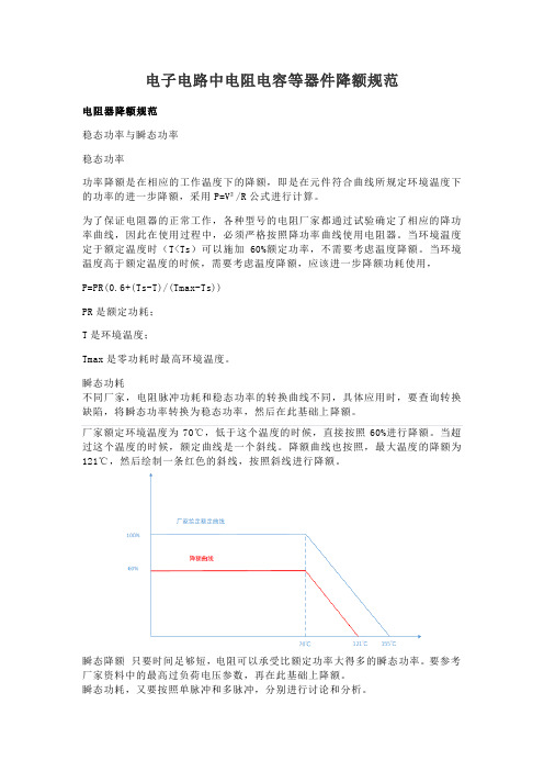
厂家额定环境温度为70℃,低于这个温度的时候,直接按照60%进行降额。
当超过这个温度的时候,额定曲线是一个斜线。
降额曲线也按照,最大温度的降额为121℃,然后绘制一条红色的斜线,按照斜线进行降额。
瞬态降额只要时间足够短,电阻可以承受比额定功率大得多的瞬态功率。
要参考厂家资料中的最高过负荷电压参数,再在此基础上降额。
瞬态功耗,又要按照单脉冲和多脉冲,分别进行讨论和分析。
单脉冲:多脉冲:1、合成型电阻器1.1 概述合成型电阻器件体积小,过负荷能力强,但它们的阻值稳定性差,热和电流噪声大,电压与温度系数较大。
合成型电阻器的主要降额参数是环境温度、功率和电压。
1.2 应用指南a) 合成型电阻为负温度和负电压系数,易于烧坏。
因此限制其电压是必须的。
b) 在潮湿环境下使用的合成型电阻器,不宜过度降额。
否则潮气不能挥发将可能使电阻器变质失效。
c) 热点温度过高可能导致合成型电阻器内部的电阻材料永久性损伤。
d) 为保证电路长期工作的可靠性,电路设计应允许合成型电阻器有±15%的阻值容差。
电子电路中MOS管二极管降额使用规范
电子电路中MOS管二极管降额使用规范电子电路中MOS管二极管等器件降额规范二极管降额规范二极管按功能可分为普通、开关、稳压等类型二极管;按工作频率可分为二极管最高结温的降额,根据二极管相关详细规范给出的最高结温T jmax 而定,降额后的最高结温见表注:1、所有降额是在结温降额满足的情况下的要求。
2、参数额定值需要从datasheet中查询3、如果参数额定值与温度、时间无关,可直接降额4、如果参数额定值与温度有关,则选取结温最高时的参数进行降额5、如果与时间有关,则通过查找datasheet对应的时间和温度曲线,根据实际情况进行降额。
三极管MOS管降额规范晶体管最高结温的降额。
晶体管最高结温的降额,根据晶体管相关详细规范给出的最高结温Tjmax而定,降额后的最高结温见表功率晶体管安全工作区的降额半导体光电器件降额规范1 概述半导体光电器件主要有三类:发光、光敏器件或两者的结合。
发光类器件主要有发光二极管、发光数码管;光敏类器件有光敏二极管、光敏三极管;常用的光电组合器件是光电耦合器,它由发光二极管和光敏三极管组成。
高结温和结点高电压是半导体光电器件主要的破坏性应力,结温受结点电流或功率的影响,所以对半导体光电器件的结温、电流或功率均需进行降额。
2 应用指南1)发光二极管驱动电路必须限制电流,通常用一个串联的电阻来实现。
2)一般不应采用经半波或全波整流的交流正弦波电流作为发光二极管的驱动电流。
如果确要使用,则不允许其电流峰值超过发光二极管的最大直流允许值。
3)在整个寿命期内,驱动电路应允许光电耦合器电流传输比在降低15%的情况下仍能正常工作。
3 降额准则半导体光电器件电压、电流见表。
其中:a) 电压从额定值降额;b) 电流从额定值降额;最高结温降额根据光电器件相关详细规范给出的最高结温T jmax 而定。
TVS器件降额规范器件应力考核点:最大吸收电流I PM,最大吸收功率P PM,TVS 平均功率P AV,钳位电压V C,上表中P P(TAU)为TVS的额定峰值功率对应实际壳温T AU下的最大允许功率,被保护器件承受电压的降额值:D V=V C/V RA*100%说明:TVS器件在某些特殊应用时如用于开关管的电压尖峰。
元器件温度降额标准

元器件温度降额标准元器件温度降额标准是指在电子设备中使用的元器件在超出额定温度时,其性能和可靠性会受到影响,因此需要降低其工作负荷或工作温度以避免过热和潜在的损坏。
本文将详细介绍元器件温度降额标准的相关概念、原因、方法和实践。
一、元器件温度降额标准的概念元器件温度降额标准是指在电子设备中使用的元器件在超出额定温度时,为避免过热和潜在的损坏,需要降低其工作负荷或工作温度的标准。
电子设备中的元器件都有其各自的工作温度范围,当环境温度或工作温度超出其额定范围时,元器件的性能和可靠性会受到影响。
因此,为了确保电子设备的稳定性和可靠性,需要对元器件进行温度降额管理。
二、元器件温度降额的原因元器件温度降额的主要原因是过热对元器件性能和可靠性的影响。
过热会导致元器件的电气性能下降,如电阻、电容、电感等电子元件的电气性能会受到影响。
此外,过热还会导致元器件的结构和机械性能发生变化,如塑料件变形、金属件热膨胀等。
这些变化会影响元器件的寿命和可靠性,甚至会导致元器件的损坏。
因此,需要对元器件进行温度降额管理,以确保电子设备的稳定性和可靠性。
三、元器件温度降额的方法1.自然散热自然散热是指利用空气对流将热量散失的方法。
这种方法适用于中低功率的电子设备,如个人电脑、服务器等。
自然散热的关键是合理设计散热片和风道,提高散热效率。
2.强制风冷强制风冷是指利用风扇等设备强制空气流动进行散热的方法。
这种方法适用于高功率电子设备,如通信基站、大型服务器等。
强制风冷的关键是选择合适的风扇和设计合理的风道,确保空气流动畅通。
3.液冷液冷是指利用液体循环进行散热的方法。
这种方法适用于极高功率电子设备,如超级计算机、大型激光器等。
液冷的关键是选择合适的冷却液和设计合理的冷却系统,确保液体流动畅通且不发生泄漏。
四、元器件温度降额的实践在电子设备的设计和生产过程中,需要对元器件进行温度降额管理。
具体实践包括以下几个方面:1.选择合适的元器件在选择电子设备中的元器件时,需要考虑其工作温度范围和额定温度。
第2-2元器件降额使用

2.3 元器件降额使用
降额应合理(3)
合理选择降额因子
降额因子一般为0.7-0.8,不宜<0.5 降额过度的后果
增加了整机的成本、体积和重量 增加了设计难度 减少了电路的动态范围 引入 新的失效机理 功率双极晶体管:电流降额过度使hFE显著下降 塑料封装器件:功率降额过度使湿气的影响上升
表2.3 常用元器件的推荐降额范围
频率降额 降低时钟频率(微处理器)
1. 电阻器的降额使用 电阻器按其功能可分为固定电阻器、 电位器、热敏电阻器等。对于固定电阻 器和电位器而言,影响其可靠性的最重 要应力为电压、功率和环境温度;对于 热敏电阻而言,影响其可靠性的应力则 主要是功率和环境温度。
2. 电容器的降额使用 影响电容器可靠性的最重要应力是 电压和环境温度。对于固定纸/塑料薄膜 电容器而言,在应用时,交流峰值电压 与直流电压之和不得超过其额定值。
3. 半导体器件降额使用 可按 GJB/Z35《电子元器件降额准 则》对半导体器件合理地降额使用。需 要降额的主要参数是结温、电压和电流。 半导体器件的降额系数 S 取 0.5 以下, 温度低于 50℃。锗管还要低一点。不同 的半导体器件,S的定义不一样。
晶体二极管的 S 为平均正向工作电流与 25 ℃时 的最大额定正向电流之比。 晶体三极管的 S 为实际功率与 25 ℃时的最大额 定功率之比。 稳压管的 S为实际耗散功率与 25 ℃时最大额定 功率之比。 光电器件的 S为实际耗散功率与 25 ℃时最大额 定功率乘以与最大允许结温有关的修正系数之 比。
2.3 元器件降额使用微电子器件的最大额定值
- 1、下载文档前请自行甄别文档内容的完整性,平台不提供额外的编辑、内容补充、找答案等附加服务。
- 2、"仅部分预览"的文档,不可在线预览部分如存在完整性等问题,可反馈申请退款(可完整预览的文档不适用该条件!)。
- 3、如文档侵犯您的权益,请联系客服反馈,我们会尽快为您处理(人工客服工作时间:9:00-18:30)。
元件降额测试工作指引版次Revision更改详情Change description生效日期Effective Date1 初次发放本 / First Release25-Jul-20002 重新编写﹐加入英语解释 / Revised, add English translation17-Sep-20013 增加瞬态条件﹐以及使用率一览表 / Add transient condition, andderating table.17-Jan-20024 修正错误﹐增加场效应管﹐二极管﹐及稳压管测试方法。
/Correctmistake, add test method to FET, rectifier and zener.11-Jun-20025 修正错误﹐增加集成电路及光偶使用率范围﹐增加静态过载观察项目。
/ Correct mistake, add IC and opto-coupler derating limit, addobservation item in static overload test.16-Aug-20026 改变二极管的电压使用率﹐对塑料电容及磁性元件使用率加备注。
/Change voltage derating for rectifier. Add remark for derating of P-capand magnetics.07-Mar-20037 增加正激式变压器﹐镇流器﹐铁粉芯镇流器之使用率测试。
/ Add derating for forward transformer, choke, iron power choke.DE PD ST DV PMC TE Prepared on 24 November 2020如果受控印章不是蓝色,表示此文件不受控,请参考受控文件。
If the control stamp is not in blue, it means this document is not under control, please refer to controlled document.H:\Dv_dat\Wi&qsp\Wi\1. 目的/Objective元件使用率的测试是检查元件在不同的测试条件下﹐实际使用电压﹑电流和功率跟其额定值的比值﹐这是确保产品没有由于元件超出使用范围而引起损坏。
Component derating test is to check the ratio of actual voltage, current and power applied to a component against their rated value under various test conditions. This is to ensure that nocomponent is overstressed which may cause failure of the product.2. 范围/Scope适用于柏怡电子厂开发的所有产品。
Applicable to all products developed by PI Electronics.3. 使用仪器/Main equipment●在工程样板1(EVT)和工程样板2(DVT)阶段﹐所有元件均必须测试。
●数字存储示波器/Storage oscilloscope●数字万用表 /DVM●电子负载/Electronic load●有效值数字表/RMS meter●电流探头/Current probe4. 步骤/Procedure使用率测试覆盖范围/Test coverage●在工程样板1(EVT)和工程样板2(DVT)阶段﹐所有元件均必须测试。
All components shall be tested once in EVT stage, once in DVT stage.●在工程样板2(DVT)阶段后﹐如有任何元件改变﹐则只重检由于改变而影响的元件。
If there is any component change after DVT, recheck components affected by the change.测试条件/Test condition除非有特别规定﹐否则使用下列定义﹕Unless otherwise specifed, following definition were used.●最大输入电压﹕264Vac(对于仅用110V供电的产品则用135Vac)Max Vin : 264Vac (or 135Vac for 110Vac only system)●最小输入电压﹕90Vac (对于仅用220V供电的产品则用180Vac)Min Vin : 90Vac (or 180Vac for 220Vac only system)●最大输出负载﹕最大的连续负载Max load : maximum continuous load.●最小输出负载﹕最小的连续负载Min load : minimum continuous load.除非有特别规定﹐正常工作条件的使用率测试必须在室温下对所有元件并按下列三种条件进行测试﹕Unless otherwise specified, nominal condition derating test shall be done for all components at room temperature under following 3 conditions.●最大输入电压﹐最大输出负载/Max Vin, max load.●最大输入电压﹐最小输出负载/Max Vin, min load.●最小输入电压﹐最大输出负载/Min Vin, max load.除非有特别规定﹐浪涌/瞬态使用率必须对关键性元件﹐例如﹕开关管﹐输出整流管。
在高温及低温下按下列条件进行测试﹕Unless otherwise specified, surge/transient derating shall be done for critical components, .switching FET, output rectifiers at both low and high temperature under following conditions:●最大输入电压﹐最大输出负载﹐起机 /. Max Vin, max load, start up●最小输入电压﹐最大输出负载﹐关机 /. Min Vin, max load, shutdown●最大输入电压﹐最小输出负载﹐起机 /. Max Vin, min load, start up●最小输入电压﹐最小输出负载﹐关机 /. Min Vin, min load, shutdown●最大输入电压﹐最小输出负载﹐输出短路 /. Max Vin, min load, output short circuit●最大输入电压﹐输出短路然后起机 /. Max Vin, output short circuit, then start up使用率的要求/Derating requirement●对于NJRC的产品﹐参阅NJRC的使用率表。
For NJRC product, refer to NJRC derating table.●对于其它的产品﹐参阅柏怡电子厂内部使用率表或客户提供的使用率表。
For other products, refer to PI internal derating table or the derating table provided bycustomer.测试方法 /Test method由于在输入大电容上100赫兹的纹波电压﹐用示波器测量时峰值电压或电流会有跳动﹐因此示波器的触发模式应设定为“正常”﹐然后调节触发电平去找出最大的峰值电压或电流。
Due to 100Hz ripple voltage in bulk capacitor, the peak voltage or current measurement with oscilloscope will also vary at 100Hz. So the trigger mode of oscilloscope shall be set to 'Normal', then adjust the trigger level to find the maximum peak voltage or current.A. 静态条件 /Static condition必须记录关键性元件的电压和电流波形﹕例如开关管﹐输出整流管。
Voltage and current waveform shall be captured for critical components: . switching FET,output rectifiers.B. 瞬态条件 /Transient condition每个测试必须记录两个波形。
使用单一模式获得。
一个波形用慢速的Hor/Div设置以便整个变化能观察到。
一个波形用快速的Hor/Div设置显示2~3个周期﹐调节触发点来得到电压或电流的峰值。
两者的波形的峰值必须能对应。
Two waveforms shall be captured for each test. Use single mode acquisition. One waveform witha slow Hor/Div setting so that the whole transition can be seen. One waveform with a fastHor/Div setting to display 2 or 3 period, adjust the trigger position to find the peak voltage or current waveform. The peak in both waveform shall be correspond.从这些波形﹐可以得到电压或电流的峰值和计算使用率。
From the waveform, find the peak voltage or current and calculate the derating.电阻/ResistorA. 功率/Power●用RMS 表测量电阻两端的电压﹐根据P=U2/R计算出使用功率﹐有效值表的低端必须连接到电阻稳定且没有电压跳动的一端。
Measure RMS voltage across resistor, calculate power with the formula P=U^2/R. Lo terminal of RMS meter shall be connected to the resistor end with no voltage swing.●如果电阻两端的电压都有跳动﹐则If both end of the resistor is swinging, then.-如果只有交流电流过电阻﹐用一个交流电流探头和有效值表测量流过电阻的电流。
