Impinj英频杰产品手册
RFID基础问题100问

RFID基础问题100问RFID1、什么是射频?一般指微波,微波是指波长为0.1—100厘米或频率在1—100GHZ的电磁波。
2、什么是RFID?射频识别即RFID(Radio Frequency IDentification)技术,又称电子标签、无线射频识别,是一种通信技术,可通过无线电讯号识别特定目标并读写相关数据,而无需识别系统与特定目标之间建立机械或光学接触。
3、RFID的产业链?RFID分为芯片设计与制造、天线的设计与制造、标签封装、读写器制造、系统集成。
4、无线射频技术的原理?标签进入磁场后,接收解读器发出的射频信号,凭借感应电流所获得的能量发送出存储在芯片中的产品信息(Passive Tag,无源标签或被动标签)或者主动发送某一频率的信号(Active Tag,有源标签或主动标签);解读器读取信息并解码后,送至数据管理系统进行有关数据处理。
5、电感耦合与电磁反向散射耦合的应用?电感耦合一般适合于低频和高频近距离射频识别系统,电磁反向散射耦合主要应用于超高频和微波的远距离射频识别系统。
6、被动,半主动和主动射频系统有什么区别?主动射频系统利用标签中的内置电源在标签周围形成有效活动区,标签能够主动获得位置很低或高处以及距离较远的射频,并传送到解读器中。
被动系统中,由解读器发出射频激活标签,被动系统需要较强的射频信号,所以当解读器和标签距离较近时才能发挥作用。
半主动系统使用内部能量监测周围环境,但也需要解读器发出射频激活标签发出信号。
半主动和被动的区别是半自动系统中有内部能量,标签能够发挥其他作用,例如监测周围环境的温度,震荡情况等,也可以扩展射频活动范围。
7、什么是同时识别功能?标签上的数据是通过射频/无线电波的形式发送,并不要求目标物体在视野范围之内,加上处理数据块的特点,解读器能够达到每秒钟辨认1000个标签的速度。
大多数RFID系统能够同时收集到天线范围内的大量标签数据。
这种特性被称为同时识别功能。
OctaneSdkWorkbook_net英频杰(Impinj)读写器sdk使用手册

REV 1.0 2010-12-14 Proprietary and Confidential Copyright © 2010, Impinj, Inc.Impinj, Octane, and Speedway are eitherregistered trademarks or trademarks of Impinj, Inc.For more information, contact rfid_info@Octane 1.0 C# SDK Workbook2. Proprietary and Confidential Revision 1.0, Copyright © 2010 Impinj, Inc.ContentsIntroduction (4)Key Features (4)Getting Started with the Octane SDK (4)Pre Workshop Tasks (4)Task 1 Computer and Reader (4)Task 2–Unzip SDK (5)Task 3 – Install Visual C# 2010 Express (5)Task 4 – Exercise Examples (5)Task 5 Preparing for Exercises..................................................................................................7 Settings 10Query, Save, and Load Settings (11)Read Tags Synchronously (13)Read Tags Asynchronously (15)Read Tags Using Periodic Trigger (17)Read Tags Using GEN 2 Filter (18)Read User Memory (20)Read Serialized TID (22)Tag Access (24)Program EPC (25)Program User Memory (26)Kill Tags .....................................................................................................................................28 GPIO 30General Purpose Inputs (31)General Purpose Outputs (34)Subscribe, Test Power, and Thread (36)Subscribing to Reader Events (36)Power Ramp (37)Proper Threading Technique using Windows Presentation Format (WPF) (40)Notices: (45)Octane 1.0 SDK C# WorkbookRevision 1.0, Copyright © 2010 Impinj, Inc. Proprietary and Confidential 3.FiguresFigure 1 Speedway Reader Connections (5)Figure 3 Viewing Codin in C# OctaneSdk Sample (6)Figure 4 Visual Studio New Project Dialog Box (7)Figure 5 Visual Studio Adding References for OctandSdk (8)Figure 6 Visual Studio Add Reference Dialog Box (8)Figure 7 Adding Impinj.OctaneSdk Reference to C#.NET Program.cs ......................................... 8 Figure 8 EPC Gen 2 tag memory banks including EPC (1, or 01 in binary), TID (2, or 10) andUser (3 or 11). (13)Figure 9 Memory and features available on Monza 4 models (13)Figure 10 Impinj GPIO Connectivity Box (31)Figure 11 New WFP Project Dialog (40)Figure 12 WPF Code form (40)Figure 13 WPF Form Example (41)Octane 1.0 C# SDK Workbook4. Proprietary and Confidential Revision 1.0, Copyright © 2010 Impinj, Inc.IntroductionThe Octane SDK includes the core library that increases the usability of the Impinj Reader by simplifying the creation of Reader applications. It does this by acting as a wrapper for extracting, modifying, and the application of a Reader’s Low Level Reader Protocol (LLRP) settings. This provides high-level control over Reader settings, tag query, and tag-write operations which reduces the effort necessary to manipulate Reader functionality.Font Group Example StyleCode command Example 1 Reader =>File namesOctanesdk.zip Example codeusing Impinj.OctaneSdk; namespace QueryReaderSettingsKey FeaturesThe core library is delivered in multiple programming languages and is completed by a variety of documentation. On-Reader applications (C++ only) are written in the same manner as off-Reader applications, and all programming languages have a consistent implementation. The documentation is available in traditional online help .chm files, and also includes examples and templates:• Speedway Reader API• C#, C++ Linux• Examples, Templates, and Online HelpGetting Started with the Octane SDKThe Octane SDK is delivered in binary form as a DLL. Sample content is delivered as source code. Before the exercises in this workbook can be accomplished, the SDK must be unzipped. Visual Studio 2010 (VS2010) C# Express must be installed.Pre Workshop TasksTask 1 Computer and Reader1. Acquire a computer and Revolution Reader, and then network them together.2. To complete the tag access exercise, a Reader antenna and a few tags are required. Use Monza 4tags if available, but any EPC GEN 2 type will work.3. Connect the GPIO board or GPIO Connector Box to the multi-purpose DE15 connector, andconnect the Reader antenna to port 1 as shown in Figure 1 below.Octane 1.0 SDK C# WorkbookRevision 1.0, Copyright © 2010 Impinj, Inc. Proprietary and Confidential 5.Figure 1 Speedway Reader ConnectionsTask 2–Unzip SDK1. Octanesdk.zip contains the libraries, technical reference (Help text), and this Workbook.2. Unzip the file to a local directory.Note: This tutorial is included with the OctaneSdk. If you update to a new OctaneSdk version, check the OctaneSdk web page for a current version of this document.Task 3 – Install Visual C# 2010 ExpressTo install VS2010 C# Express, complete the following steps:1.Download and run the VS2010 installer, here:/express/downloads/#2010-Visual-CS .2. Restart your computer to complete the installation process. .3. Launch VS2010 and allow it to complete the one-time initialization process. This should take about 2 to 3 minutes.Task 4 – Exercise Examples1. From VS2010, select File, then Open Project.2. Select the /octane/cs/sdk/OctaneSdk.sln . file.3. Complete the file conversion. (This sample file was built using VS 2008.)Octane 1.0 C# SDK Workbook6. Proprietary and Confidential Revision 1.0, Copyright © 2010 Impinj, Inc.4. Right click on the desired program file (xxxxx.cs ) and then select View Code to view the code foreach project. See Figure 3.Figure 2 Viewing Codin in C# OctaneSdk Sample5. In the Solution Explorer, right click on Example1_QueryFeatures and then select Set As StartUpProject.6. Select Debug, and then Start Debugging. Enter your Reader’s name at the prompt and press enter.7. When done reviewing the Reader’s details, press any key to exit.Figure 1Exercise Example 1prompt: Example 1 Reader => {your reader’s name or IP address} output: Model Speedway R220 Software Version 4.4.1.3 Firmware Version 4.4.0.17 PCBA Version 270-001-003 FPGA Version 4.4.0.240 Regulator Region ETSI_EN_302_208_v1_2_1 Antennas 1:Connected 2:Unconnected 3:N/A 4:N/A prompt: Done => {press any key}Octane 1.0 SDK C# WorkbookRevision 1.0, Copyright © 2010 Impinj, Inc. Proprietary and Confidential 7.Note: The output from your Reader will be different from the above example, depending on the Reader model, region, and version information.8. Build and run the other examples to increase your skill using the SDK. Right click the Exampleproject, select Set As StartUp Project, and then Debug, and finally Start Debugging.Task 5 Preparing for Exercises1. For each exercise, create a new project by clicking File, and then New Project.2. Select Console Application as the template type in the New Project dialog3. Name the New Project something easy to remember. By default the project will be created in MyDocuments/Visual Studio 2010/Projects. See Figure 4.The project will be created in its ownfolder.Figure 3 Visual Studio New Project Dialog Box3. Select Solution Explorer and right click on the References folder, and then select Add Reference.Each time a project is created, the SDK libraries must be imported into the new project.Octane 1.0 C# SDK Workbook8. ProprietaryFigure 4 Visual S4. Browse to /OctaneSdk/Libr5. Click OK.Figure 5 Vis6. Type “using Impinj.OctaneIntellisense helps with thisFigure 6 Adding Impin7.Select File and then Save AOctane 1.0 SDK C# WorkbookRevision 1.0, Copyright © 2010 Impinj, Inc. Proprietary and Confidential 9.The new project is now prepared for the exercises.Octane 1.0 C# SDK Workbook10. Proprietary and Confidential Revision 1.0, Copyright © 2010 Impinj, Inc.SettingsSpeedway Readers have a wide range of capabilities. With so many capabilities, it requires configuration to reduce them to a manageable subset. The capabilities can be thought of as a programming language, or a set of tools waiting for a purpose. That purpose is defined by Reader settings. The settings are aprogram that describes what capabilities are used and how they behave. That means that the operation of Reader is critically dependent on the proper settings. The application depends upon the Reader. As a programmer, you must understand the settings and how they affect the Reader’s operation.The easiest way to get guaranteed success changing a Reader’s settings is to have the library catalog a default, or “best guess” settings object. Once that object is returned, the Reader settings can be changed with the default. Settings can be modified in code, written to disk, edited, and loaded back in. Settings are expressed as XML on disk, and also as a class .Query Services NameDescription QueryFactorySettingsDetermines most basic settings from the Reader’s capabilities and features. QuerySettingsIf the settings were changed, this returns current settings configuration. QueryFeatureSetDefinition of features that are available on the Reader. QueryStatus The current state of the Reader, antennas,and more.Command Services NameDescription ConnectConnects to a Reader allowing query and command services to transact. DisconnectAfter disconnect, no services are available until next connect. ClearSettingsDeletes the Readers settings and returns to the factory default settings. ApplySettings Replaces theReader’s current settings with the passed-in settings.Query, Save, and Load SettingsIn the following exercise you will connect to the Reader, save settings to an XML file, then edit and load the XML file to apply changes to the Reader settings.using System;using System.Collections.Generic;using System.Linq;using System.Text;using Impinj.OctaneSdk;namespace QueryReaderSettings{class Program{// Create an instance of the SpeedwayReader class.static SpeedwayReader Reader = new SpeedwayReader();static void DisplayCurrentSettings(){// Query the current reader settings and print the results.Console.WriteLine("Reader Settings");Console.WriteLine("---------------");Settings settings = Reader.QuerySettings();Console.WriteLine("Reader mode : {0}", settings.ReaderMode);Console.WriteLine("Search mode : {0}", settings.SearchMode);Console.WriteLine("Session : {0}", settings.Session);Console.WriteLine("Rx sensitivity (Antenna 1) : {0} dBm",settings.Antennas[1].RxSensitivityInDbm);Console.WriteLine("Tx power (Antenna 1) : {0} dBm",settings.Antennas[1].TxPowerInDbm);Console.WriteLine("");}static void Main(string[] args){try{// Connect to the reader.// Replace "SpeedwayR-xx-xx-xx" with your// reader's host name or IP address.Reader.Connect("SpeedwayR-xx-xx-xx");// Query the reader features and print the results.Console.WriteLine("Reader Features");Console.WriteLine("---------------");FeatureSet features = Reader.QueryFeatureSet();Console.WriteLine("Model name : {0}", features.ModelName);Console.WriteLine("Model number : {0}", features.ModelNumber);Console.WriteLine("Reader identity : {0}", features.ReaderIdentity);Console.WriteLine("Firmware version : {0}",features.FirmwareVersion);Console.WriteLine("Antenna count : {0}\n", features.AntennaCount);// Write the reader features to file.features.Save("features.xml");Revision 1.0, Copyright © 2010 Impinj, Inc. Proprietary and Confidential11.// Query the current reader status.Console.WriteLine("Reader Status");Console.WriteLine("---------------");Status status = Reader.QueryStatus();Console.WriteLine("Is connected : {0}", status.IsConnected);Console.WriteLine("Is singulating : {0}", status.IsSingulating);Console.WriteLine("Temperature : {0} degrees\n",status.TemperatureInCelsius);// Configure the reader with the factory deafult settings.Reader.ApplyFactorySettings();// Display the current reader settings.DisplayCurrentSettings();// Save the settings to file in XML format.Console.WriteLine("Saving settings to file.");Settings settings = Reader.QuerySettings();settings.Save("settings.xml");// Wait here, so we can edit the// settings.xml file in a text editor.Console.WriteLine("Edit settings.xml and press enter.");Console.ReadLine();// Load the modified settings from file.Console.WriteLine("Loading settings from file.");settings = Settings.Load("settings.xml");// Apply the settings we just loaded from file.Console.WriteLine("Applying settings from file.\n");Reader.ApplySettings(settings);// Display the settings again to show the changes.DisplayCurrentSettings();// Disconnect from the reader.Reader.Disconnect();}catch (OctaneSdkException e){Console.WriteLine("Octane SDK exception : {0}", e.Message);}catch (Exception e){Console.WriteLine("Exception : {0}", e.Message);}// Wait for the user to press enter.Console.WriteLine("Press enter when done.");Console.ReadLine();}}}12.Proprietary and Confidential Revision 1.0, Copyright © 2010 Impinj, Inc.Revision 1.0, Copyright © 2010 Impinj, Inc. Proprietary and Confidential13.There are three memory banks on an EPC GEN 2 tag that you need to know how to query: the Electronic Product Code (EPC), User Memory, and Tag Identification (TID).Figure 7 EPC Gen 2 tag memory banks including EPC (1, or 01 in binary), TID (2, or 10)and User (3 or 11).Note: the data locations in figure 8. Focus attention on the EPC. The actual EPC begins at word2 (or hex address 20). Prior to the EPC is the 16 bit Cyclic Redundancy Check or CRC (word 0)and the Protocol Control (or PC) word (word 1).The exercises in this section enable you to read the three memory banks using two different approaches: synchronously and asynchronously. You will also apply the feature sets of the SDK such as filters where only tags with specific data will respond and serialized TID (tag returns EPC and TID together using one command). Figure 8 shows the memory available for the various version of the Impinj Monza 4 tag IC.Figure 8 Memory and features available on Monza 4 modelsRead Tags SynchronouslyIn this exercise, you will configure the Reader so that observed tag data is stored in Reader memory and a report of all observed tags is sent only when commanded by the client application.using System;using System;using System.Collections.Generic;using System.Linq;using System.Text;using Impinj.OctaneSdk;namespace ReadTagsSync{class Program{// Create an instance of the SpeedwayReader class.static SpeedwayReader Reader = new SpeedwayReader();static void Main(string[] args){try{// Connect to the reader.// Replace "SpeedwayR-xx-xx-xx" with your// reader's host name or IP address.Reader.Connect("SpeedwayR-xx-xx-xx");// Remove all settings from the reader.Reader.ClearSettings();// Get the factory default settings// We'll use these as a starting point// and then modify the settings we're// interested inSettings settings = Reader.QueryFactorySettings();// Tell the reader to include the antenna number// in all tag reports. Other fields can be added// to the reports in the same way by setting the// appropriate Report.IncludeXXXXXXX property.settings.Report.IncludeAntennaPortNumber = true;// Wait until the tag query has ended// before sending the tag report.settings.Report.Mode = ReportMode.WaitForQuery;// Apply the newly modified settings.Reader.ApplySettings(settings);// Read tags for 5 secondsConsole.WriteLine("Reading tags...");TagReport tagReport = Reader.QueryTags(5);// Print out the results.foreach (Tag tag in tagReport.Tags){Console.WriteLine("EPC : {0} Antenna : {1}",14.Proprietary and Confidential Revision 1.0, Copyright © 2010 Impinj, Inc.tag.Epc, tag.AntennaPortNumber);}// Disconnect from the reader.Reader.Disconnect();}catch (OctaneSdkException e){Console.WriteLine("Octane SDK exception: {0}", e.Message);}catch (Exception e){Console.WriteLine("Exception : {0}", e.Message);}// Wait for the user to press enter.Console.WriteLine("Press enter when done.");Console.ReadLine();}}}Read Tags AsynchronouslyIn this exercise, you will configure the reader to report each tag to the client application as soon as it is observed. This is known as “asynchronous reporting”.using System;using System.Collections.Generic;using System.Linq;using System.Text;using Impinj.OctaneSdk;namespace ReadTagsAsync{class Program{// Create an instance of the SpeedwayReader class.static SpeedwayReader Reader = new SpeedwayReader();static void Main(string[] args){try{// Connect to the reader.// Replace "SpeedwayR-xx-xx-xx" with your// reader's host name or IP address.Reader.Connect("SpeedwayR-xx-xx-xx");// Remove all settings from the reader.Reader.ClearSettings();// Get the factory default settings// We'll use these as a starting point// and then modify the settings we're// interested inSettings settings = Reader.QueryFactorySettings();// Tell the reader to include the antenna numberRevision 1.0, Copyright © 2010 Impinj, Inc. Proprietary and Confidential15.// in all tag reports. Other fields can be added// to the reports in the same way by setting the// appropriate Report.IncludeXXXXXXX property.settings.Report.IncludeAntennaPortNumber = true;// Send a tag report for every tag read.settings.Report.Mode = ReportMode.Individual;// Apply the newly modified settings.Reader.ApplySettings(settings);// Assign the TagsReported handler.// This specifies which function to call// when tags reports are available.Reader.TagsReported += new EventHandler<TagsReportedEventArgs>(OnTagsReported);// Start reading.Reader.Start();// Wait for the user to press enter.Console.WriteLine("Press enter when done.");Console.ReadLine();// Stop reading.Reader.Stop();// Disconnect from the reader.Reader.Disconnect();}catch (OctaneSdkException e){Console.WriteLine("Octane SDK exception: {0}", e.Message);}catch (Exception e){Console.WriteLine("Exception : {0}", e.Message);}}static void OnTagsReported(object sender, TagsReportedEventArgs args){// This function is called asynchronously// when tag reports are available.// Loop through each tag in the report// and print the data.foreach (Tag tag in args.TagReport.Tags){Console.WriteLine("EPC : {0} Antenna : {1}",tag.Epc, tag.AntennaPortNumber);}}}}16.Proprietary and Confidential Revision 1.0, Copyright © 2010 Impinj, Inc.Read Tags Using Periodic TriggerThere may be cases where you want the reader to conduct ‘polling’ or examination for tags. During polling, the reader initiates a scan for tags for a specified period of time and then waits for a set period before scanning again. An example of this would be a “smart-shelf” application where the user does not need to know the instant that a tagged item is placed on, or removed from the shelf. Updating polling every 10 seconds is sufficient and reduces both network and RF congestion.There are a number of trigger types and settings available: refer to the SDK Quick Reference Guide or the SDK Compiled HTML Help File for more information.using System;using System.Collections.Generic;using System.Linq;using System.Text;using Impinj.OctaneSdk;namespace ReadTagsPeriodicTrigger{class Program{// Create an instance of the SpeedwayReader class.static SpeedwayReader Reader = new SpeedwayReader();static void Main(string[] args){try{// Connect to the reader.// Replace "SpeedwayR-xx-xx-xx" with your// reader's host name or IP address.Reader.Connect("SpeedwayR-xx-xx-xx");// Remove all settings from the reader.Reader.ClearSettings();// Get the factory default settings// We'll use these as a starting point// and then modify the settings we're// interested inSettings settings = Reader.QueryFactorySettings();// Tell the reader to include the antenna number// in all tag reports. Other fields can be added// to the reports in the same way by setting the// appropriate Report.IncludeXXXXXXX property.settings.Report.IncludeAntennaPortNumber = true;// Send a tag report for every tag read.settings.Report.Mode = ReportMode.Individual;// Reading tags for 5 seconds every 10 secondssettings.AutoStart.Mode = AutoStartMode.Periodic;settings.AutoStart.PeriodInMs = 10000;settings.AutoStop.Mode = AutoStopMode.Duration;settings.AutoStop.DurationInMs = 5000;// Apply the newly modified settings.Reader.ApplySettings(settings);Revision 1.0, Copyright © 2010 Impinj, Inc. Proprietary and Confidential17.// Assign the TagsReported handler.// This specifies which function to call// when tags reports are available.Reader.TagsReported += new EventHandler<TagsReportedEventArgs>(OnTagsReported);// Wait for the user to press enter.Console.WriteLine("Press enter when done.");Console.ReadLine();// Stop reading.Reader.Stop();// Disconnect from the reader.Reader.Disconnect();}catch (OctaneSdkException e){Console.WriteLine("Octane SDK exception: {0}", e.Message);}catch (Exception e){Console.WriteLine("Exception : {0}", e.Message);}}static void OnTagsReported(object sender, TagsReportedEventArgs args){// This function is called asynchronously// when tag reports are available.// Loop through each tag in the report// and print the data.foreach (Tag tag in args.TagReport.Tags){Console.WriteLine("EPC : {0} Antenna : {1}",tag.Epc, tag.AntennaPortNumber);}}}}Read Tags Using GEN 2 FilterThe Impinj Revolution Reader and Monza tags support what is known as GEN 2 filtering. There are two possible approaches to take when you only want to read certain tags based on their data. You can either use either EPC, User, TID, or a combination of these. One is to have all the tags in the read- zone and backscatter their data to the reader, then use filtering in the application layer (your program).The other method, which you will utilize here, is to configure the reader so that it commands only tags matching the filter to respond while the others will stay silent. This is useful when applied in the physical layer: only tags matching the filter will backscatter data and it can decrease the amount of RF and tag-to-tag interference.using System;18.Proprietary and Confidential Revision 1.0, Copyright © 2010 Impinj, Inc.using System.Collections.Generic;using System.Linq;using System.Text;using Impinj.OctaneSdk;namespace ReadTagsFiltered{class Program{// Create an instance of the SpeedwayReader class.static SpeedwayReader Reader = new SpeedwayReader();static void Main(string[] args){try{// Connect to the reader.// Replace "SpeedwayR-xx-xx-xx" with your// reader's host name or IP address.Reader.Connect("SpeedwayR-xx-xx-xx");// Remove all settings from the reader.Reader.ClearSettings();// Get the factory default settings// We'll use these as a starting point// and then modify the settings we're// interested inSettings settings = Reader.QueryFactorySettings();// Tell the reader to include the antenna number// in all tag reports. Other fields can be added// to the reports in the same way by setting the// appropriate Report.IncludeXXXXXXX property.settings.Report.IncludeAntennaPortNumber = true;// Send a tag report for every tag read.settings.Report.Mode = ReportMode.Individual;// Setup a tag filter.// Only the tags that match this filter will respond.// We're only going to use filter #1.settings.Filters.Mode = TagFilterMode.OnlyFilter1;// We want to apply the filter to the EPC memory bank.settings.Filters.TagFilter1.MemoryBank = MemoryBank.Epc;// Start matching at address 0x20, since the// first 32-bits of the EPC memory bank are the// CRC and control bits.settings.Filters.TagFilter1.BitPointer = 0x20;// Our filter is 16-bits long (the first word of the EPC).settings.Filters.TagFilter1.BitCount = 16;// Only match tags with EPCs that start with "3008"settings.Filters.TagFilter1.TagMask = "3008";// We want to include tags that match this filter.// Alternatively, we could exclude tags that// match the filter.settings.Filters.TagFilter1.FilterOp = TagFilterOp.Match;// Apply the newly modified settings.Reader.ApplySettings(settings);Revision 1.0, Copyright © 2010 Impinj, Inc. Proprietary and Confidential19.// Assign the TagsReported handler.// This specifies which function to call// when tags reports are available.Reader.TagsReported += new EventHandler<TagsReportedEventArgs>(OnTagsReported);// Start reading.Reader.Start();// Wait for the user to press enter.Console.WriteLine("Press enter when done.");Console.ReadLine();// Stop reading.Reader.Stop();// Disconnect from the reader.Reader.Disconnect();}catch (OctaneSdkException e){Console.WriteLine("Octane SDK exception: {0}", e.Message);}catch (Exception e){Console.WriteLine("Exception : {0}", e.Message);}}static void OnTagsReported(object sender, TagsReportedEventArgs args){// This function is called asynchronously// when tag reports are available.// Loop through each tag in the report// and print the data.foreach (Tag tag in args.TagReport.Tags){Console.WriteLine("EPC : {0} Antenna : {1}",tag.Epc, tag.AntennaPortNumber);}}}}Read User MemoryThe Impinj Monza 4 tags offer up to 512 bits of user memory. In this exercise you will query the user memory using exception handling best practices.using System;using System.Collections.Generic;using System.Linq;using System.Text;using Impinj.OctaneSdk;namespace ReadUserMemory{class Program20.Proprietary and Confidential Revision 1.0, Copyright © 2010 Impinj, Inc.{// Create an instance of the SpeedwayReader class.static SpeedwayReader Reader = new SpeedwayReader();static void Main(string[] args){try{// Connect to the reader.// Replace "SpeedwayR-xx-xx-xx" with your// reader's host name or IP address.Reader.Connect("SpeedwayR-xx-xx-xx");// Configure the reader with the factory deafult settings.Reader.ApplyFactorySettings();// Define how we want to perform the read.ReadUserMemoryParams readParams = new ReadUserMemoryParams();// Use antenna #1.readParams.AntennaPortNumber = 1;// No access password required for this tag.readParams.AccessPassword = null;// Start reading from the base of user memory (address 0).readParams.WordPointer = 0;// Read 32 words of user memory (512-bits).readParams.WordCount = 32;// Read the first tag we see.// Alternatively, we could choose a specific// tag by EPC or other identifier.readParams.TargetTag = null;// Timeout in 5 seconds if the read operation fails.readParams.TimeoutInMs = 5000;// Perform the read and check the results.ReadUserMemoryResult result = Reader.ReadUserMemory(readParams);if (result.ReadResult.Result == AccessResult.Success){Console.WriteLine("Tag read successful. Memory contents : {0}", result.ReadResult.ReadData);}else{Console.WriteLine("Error reading tag : {0}",result.ReadResult.Result);}// Disconnect from the reader.Reader.Disconnect();}catch (OctaneSdkException e){Console.WriteLine("Octane SDK exception: {0}", e.Message);}catch (Exception e){Console.WriteLine("Exception : {0}", e.Message);}。
杰基国际产品说明书

Pin AssignmentsDB-25 and DB-9 Pin AssignmentsRJ-45 Pin Assignments for 10-Pin and 8-Pin RJ-45 ConnectorsRefer to the Digi CD for more detailed cabling information or visit for more information.Digi, the Digi Connectware logo, AccelePort, and Digi Neo are trademarks or registeredtrademarks of Digi International in the United States and other countries. All other brandand product names are trademarks of their respective holders.© Digi International Inc., 2001, 2002, 2003 All Rights Reserved; Information in this document is subject to change without notice and does not represent acommitment on the part of Digi International.Digi provides this document “as is,” without warranty of any kind, either expressed orimplied, including, but not limited to, the implied warranties of fitness or merchantabilityfor a particular purpose. Digi may make improvements and/or changes in this manual or inthe product(s) and/or the program(s) described in this manual at any time.This product could include technical inaccuracies or typographical errors. Changes are peri-odically made to the information herein; these changes may be incorporated in new editionsof the publication.Digi NeoPCI Host AdaptersEIA-232Hardware InstallationGuideIntroductionA Digi Neo™ adapter easily expands the number of EIA-232 portsavailable on your computer, allowing you to cable additional peripheraldevices, such as modems, terminals or serial printers, directly to yourcomputer.The Digi Neo 2 port adapter has two connectors (DB-9 or RJ-45) on theadapter to provide peripheral port connections.Digi Neo 4 and 8 port adapters are equipped with an HD-68 connector towhich a special Digi connector assembly is attached to provide theperipheral port connections. There are seven different connector assem-bly options available to use with Digi Neo 4 and Neo 8 adapters:•RJ-45 Connector Box•DB-25 Connector Box (male connectors)•DB-9 Connector Box (male connectors)•DB-25 Fan-out Cable (male or female connectors)•DB-9 Fan-out Cable (male or female connectors)This installation guide describes how to plan your setup and install a DigiNeo adapter.Signal Description DB-25 Pin DB-9 Pin GND Chassis Ground Shell Shell TxD Transmitted Data23 RxD Received Data32 RTS Request To Send47CTS Clear To Send58DSR Data Set Ready66SG Signal Ground75DCD Data Carrier Detect81DTR Data Terminal Ready204RI Ring Indicator229Signal Description Pin # (of 10)Pin # (of 8)RI Ring Indicator1N/ADSR Data Set Ready2†1†RTS Request To Send32GND Chassis Ground43TxD Transmitted Data54RxD Received Data65SG Signal Ground76CTS Clear To Send87DTR Data Terminal Ready98DCD Data Carrier Detect10N/A† DSR (Pin 2 on a 10 pin connector, Pin 1 on an 8 pin connector)can be swapped with DCD by using the ALTPIN configurationoption. ALTPIN reverses the position of these two signals in 10pin connectors and allows DCD to be used instead of DSR on an8 pin connector.Consult the driver documentation for how to do this in yourspecific operating system.91001071_BStep One: Plan Your SetupA Digi Neo adapter can be set up in a variety of ways. Before you start your installation, consider the following:Number of Components. You can connect two peripheral devices to a Digi Neo 2, up to four peripheral devices to a Digi Neo 4, and eight periph-eral devices to a Digi Neo 8 adapter. Up to four Digi Neo adapters may be installed in a computer.Construction of Cables. To achieve the greatest reliability over distance, cables should be:•Shielded, low capacitance, and preferably designed specifically for serial data transmission.•Grounded at both ends of the cable.•Routed away from noise sources such as generators, motors and fluorescent lights.Cable Connections. Before beginning the installation, verify that you have the appropriate Digi connector assemblies (fan-out cables or connec-tor box assemblies). Fan-out cable and connector box options aredescribed in detail in a separate Cable Usage Guide.You will also need a cable for each peripheral that you will be attach-ing to the connector assembly. The connector type that you need at either end of the peripheral cable depends on the type of Digi connec-tor assembly that you use and the connector on the peripheral.Digi connector assemblies are available with RJ-45, DB-25 or DB-9 connectors. You will need to be sure that you have cables of the cor-rect length and with the right connectors to properly attach thedevices you want to use.Additional information about the Digi Neo adapter, such as specifications and cabling details, is provided on the Digi CD which is packaged with the adapter.Step Two: Install the Neo AdapterCAUTION! To guard against damage to the adapter due to electrostaticdischarge (ESD), do not remove the adapter from its protective packag-ing until you have grounded yourself to the computer chassis (see step 4,below).1.Shut down your computer in the manner recommended for your oper-ating system.2.Unplug power from the computer.3.Remove the computer’s cover.4.Touch the computer chassis to equalize any static potential betweenyourself and the computer. This will help prevent damage to theadapter due to electrostatic discharge.5.Locate an available PCI slot in your computer and remove the slotplate.6.Remove the adapter from its protective packaging.7.Write down the serial number of the adapter in the space providedbelow.8.Insert the adapter into the slot and screw the endplate to the computerchassis. The endplate must be screwed into the computer chassis toremain in compliance with Part 15 of FCC rules.9.Replace the computer’s cover.10.Attach the peripheral interconnect cable(s) to the adapter.CAUTION: Many SCSI adapters use the same HD-68 connector type asthe Neo adapter. Do not plug SCSI devices into the Digi connector, anddo not plug Digi peripheral cables into SCSI adapters.Serial Number: ________________________Step Three: Install Peripheral CablingYou can connect modems, terminals, serial printers, or any other standardEIA-232 device to a Digi Neo adapter using a cable between the periph-eral and the Digi connector assembly.On the peripheral end of the cable, the connector you must have dependson the requirements of the peripheral. The Digi end of the cable must beequipped with the connector type that mates with the connectors on theDigi connector assemblyIn the case of the 2 port product, the cables are connected directly to theadapter’s end-plate.。
Infinity Kappa Series 100.9w 和 120.9w 子频器说明书

K A P P A®2THANK YOU for choosing anInfinity®Kappa®Series 100.9w or 120.9wsubwoofer.These Kappa subwoofers are designed tosuit a broad range of car audio applicationsand can be used in a wide variety ofenclosure types to produce extended,powerful bass in a limited amount ofvehicle space.To get the most performancefrom your new subwoofer,it is stronglyrecommended that you have a qualifiedprofessional install your 100.9w or 120.9wsubwoofer.Although this manual doesprovide general instructions aboutinstalling these Kappa Series subwoofers,itdoes not include enclosure constructiondetails or exact installation methods forany particular vehicle.If you do not feelthat you have the necessary experience,donot attempt the installation yourself,butinstead ask your authorized Infinity dealerabout professional installation options.Remember to keep your sales receipt in asafe place,along with this manual,so thatboth are available for future reference.BOX CONTENTS(1) 100.9w or 120.9w subwoofer(1) Foam mounting gasket(1) 3mm hex wrench(1) Owner’s manual(1) Technical data sheetW ARNINGPlaying loud music in a vehicle can hinderyour ability to hear traffic and permanentlydamage your hearing.The maximum volumelevels achievable by Infinity speakers whencombined with high-power amplificationmay exceed safe levels for extendeding low volume levels isrecommended when driving.InfinitySystems accepts no liability for hearingloss,bodily injury,or property damage asa result of use or misuse of this product.REPRODUCINGBASS IN VEHICLESDepending on the size of your vehicle’sinterior listening space,reproduced bassfrequencies below 80Hz will be boostedby nearly 12dB per octave as frequencydecreases.This phenomenon,known as thevehicle’s transfer function (or cabin gain),plays an important role in shaping thesubwoofer’s frequency response in yourvehicle.The enclosed technical data sheetincludes frequency response graphs thatshow both the subwoofer’s “in-car”response (which factors in this vehicletransfer function) and its “out-of-car”response (which does not).3®45®67SPECIFICA TIONS100.9w120.9w10" (250mm)12" (300mm)SSI Automotive Subwoofer SSI Automotive SubwooferPower Handling (RMS):350W350WPower Handling (Peak):1400W1400WSensitivity @2.83V/1m:89dB91dBFrequency Response:25Hz – 400Hz23Hz – 400HzImpedance: 2 or 4 ohms (selectable) 2 or 4 ohms (selectable)Voice-Coil Diameter:2" (50mm)2" (50mm)Mounting Depth:5-15/16" (150mm)6-5/16" (160mm)Overall Diameter:10-3/4" (273mm)12-5/8" (320mm)Cutout Diameter:9-1/4" (234mm)11-3/16" (283mm)A valid serial number is required for warranty coverage.Features,specifications and appearance are subject to change without notice.These products are designed for mobile applications and are not intended for connection to the mains.。
Impinj 英频杰产品手册
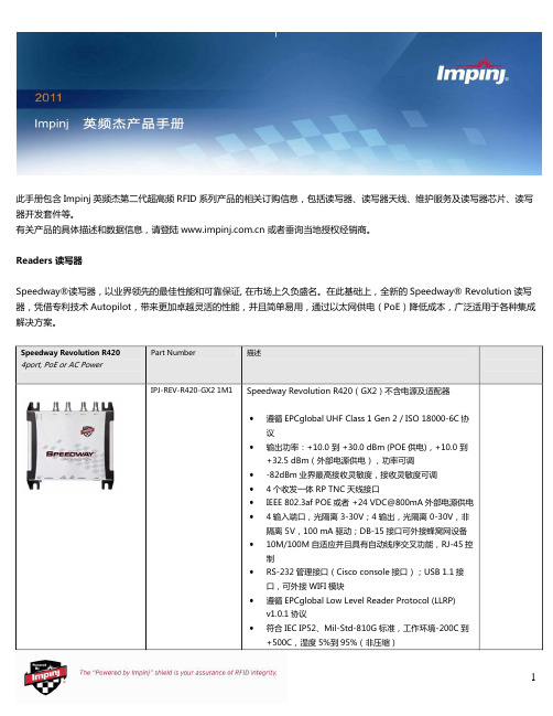
•
遵循 EPCglobal UHF Class 1 Gen 2 / ISO 18000-6C
协议
•
输出功率:+10.0 到 +30.0 dBm (POE 供电),+10.0
到 +32.5 dBm(外部电源供电),功率可调
•
-82dBm 业界最高接收灵敏度,接收灵敏度可调
•
2 个收发一体 RP TNC 天线接口
RFID 工作频段
•
内置功放+20dBm 最大输出,可配合使用外置功放,
5
Indy R2000 Chips Indy R500 Chips
Part Number
可配置数字基带
•
发射相位噪声-116 dBm/Hz@250kHz
•
-75 dBm 接收灵敏度(+5dBm 载波泄漏,DRM 模
式)
•
相关接收机架构保证了稳定的 RSSI 值以及可信的载波
Part Number IPJ-A0402-USA
Part Number IPJ-A0303-000
描述
Guardwall(FCC)(70×40×10 cm)
•
工作频段:902-928 MHz
•
极化方式:左旋和右旋极化(内置两种极化单元),
3dB 轴比(最大)
•
远场增益:+6 dBi
•
半功率波瓣宽度:55 度
可配置数字基带
•
发射相位噪声-126 dBm/Hz@250kHz
6
Indy R2000 Dev Platform
Indy R1000 Dev Platform Indy Source Code License
英频杰(Impinj) R220

适用于要求较低的应用环境。不支持R420那样的最大生产模式,包括Max Throughput FM0, Hybrid, Max Miller和自动设置单个阅读器
· 美国, 加拿大以及其他符合US FCC Part 15的地区 · 欧洲以及其他符合 ETSI EN 302 208 v1.2.1 无 LBT 地区 · Brazil, 香港, 印度, Uruguay, 越南 · 正在申请认证的地区—澳大利亚, 中国大陆, 马来西亚, 新加坡, 台湾地区,与泰国 2个专为Impinj阅读器天线优化的高性能的单极化天线端口 (RP TNC) · +10.0 to +30.0 dBm (PoE) · +10.0 to +32.5 dBm1 (外接通用电源) 注1: Speedway Revolution 需要专业人士安装,只能配对Impinj认可的天线, FCC Part 15.247 规约下.不超出 36 dBm EIRP ,其他区域有相似规定。查阅安装与操作手册以了解更多. -82 dBm
10 dB
EPCglobal 低级读写器协议 (LLRP) v1.0.1
10/100BASE-T auto-negotiate (full/half) with auto-sensing MDI/MDX for autocrossover (RJ-45)
· Sierra Wireless AirLink PinPoint XT (CDMA 或 GSM 链接(带 GPS 数据)) · Sierra Wireless AirLink Raven XT (CDMA 或 GSM 链接) (* 可从Impinj授权的合作伙伴获取)
最大接收灵敏度82dbm最大返回损耗10db应用界面epcglobal低级读写器协议llrpv101网络链接10100basetautonegotiatefullhalfautosensingmdimdxautocrossoverrj45蜂窝网络链接sierrawirelessairlinkpinpointxtcdmagsm链接带gps数据sierrawirelessairlinkravenxtcdmagsm链接可从impinj授权的合作伙伴获取ip地址配置dhcp静态or或使用组播域名系统mdns的链路本地地址lla时间同步网络时间协议ntp管理界面使用系列管理控制台端口的impinjrshell管理控制台telnet或sshsnmpv2mibii系统记录可靠的固件升级可扩展的升级机制可以按计划升级多个读写器apple商品uhf芯片rfid系统rfid配件连接器复用器切换器分安装支架会员管理超高频系列一体机系列通道系列持机系列uhf天线高频系列高频一体系列高频手持uhf电子标签inlaylabel智能卡类金属系列异型类标签hf电子标签高频inlay标签智能卡系抗金属系列lf系列产品读卡器系列电子标签系24g微波系列热销推荐impinjindyr2000rfid标签芯片您浏览过的商品清除列表查看所有空闲典型ldcpoe30dbm电源适配器30dbm电源适配器325usbflashdriveimpinjweb管理界面管理控制台rs232usingstandardciscostylemanagementcabledb9波特率
电路通信设备-ELF系列产品用户手册说明书

ELF SystemCopper / Fiber :: ELF FamilyUser ManualApplys to : ELF-1008-1100 :: ELF-1008-1200 :: ELF-1008-1800 :: ELF-3006-1100 :: ELF-3006-1800 ELF-9704-1119 :: ELF-3004-1800 :: ELF-3206-1200 :: ELF-3206-1900 :: ELF-PC12-SC00 ELF-9716-1900 :: ELF-9716-1700 :: ELF-0005-0001 :: ELF-PC12-FC00 :: ELF-SP12-SCPT ELF-SP12-FCPT :: ELF-PC12-SA00 :: ELF-SP12-SAPTTable of ContentsChapter 1: Descriptions (1)1.1 ELF Copper/Fiber System (1)1.2 ELF Modules (1)1.3 ELF Mounting Options (5)1.3.1 ELF Chassis (Model ELF-0000-2400) (5)1.3.2 Wall-Mount ELF Chassis Bracket (ELF-0000-0900) (7)1.3.3 ELF Wall Bracket (Model ELF-0000-0600) (10)1.3.4 ELF Lockable Wall-Mount Enclosure (Model ELF-0000-0800) (11)1.4 System-Level Applications (13)1.5 Installation Considerations (13)1.5.1 Location and Space (13)1.5.2 Tools and Equipment (13)1.5.3 Inspection (14)1.5.4 Technical Support (USA) (14)1.6 Specifications (14)Chapter 2: ELF DS1 Modules (17)2.1 ELF 8-Termination DSX-1, Wire-Wrap I/O (Model ELF-1008-1100) (17)2.2 ELF 8-Termination DSX-1, BNC I/O (Model 1008-1200) (19)2.3 ELF 8-Termination DSX-1, RJ48C I/O (Model ELF-1008-1800) (21)2.4 ELF 6-Termination DSX-1, Wire-Wrap I/O (Model ELF-3006-1100) (23)2.5 ELF 6-Termination DSX-1, RJ48C I/O (Model ELF-3006-1800) (24)2.6 ELF 4-Circuit DNI-1, Wire-Wrap I/O to RJ48C I/O (Model ELF-9704-1119) (25)2.7 ELF 4-Circuit DNI-1, RJ48C I/O to RJ48C I/O (Model ELF-3004-1800) (27)Chapter 3: ELF DS3 Modules (29)3.1 ELF 2-Termination DSX-3, Rear BNC I/O (Model ELF-3206-1200) (29)3.2 ELF 1-Termination DSX-3, TFA BNC I/O (Model ELF-3206-1900) (31)Chapter 4: ELF Fiber Modules (33)4.1 ELF Fiber Patch Modules (Model Series ELF-PC12) (33)4.2 ELF Fiber Splice/Patch Modules (Model Series ELF-SP12) (34)Chapter 5: ELF Multi-Purpose Modules (37)5.1 ELF RJ45C to RJ45C Patch Module (Model ELF-9716-1900) (38)5.2 ELF RJ45-IDC Patch Module (Model ELF-9716-1700) (39)5.3 ELF 12 x 4 Alarm Pin Block Module (Model ELF-0005-0001) (40)Chapter 6: Service (41)6.1 Owner Maintenance (41)6.2 Service (41)6.2.1 In-Warranty Service (41)6.2.2 Out-Of-Warranty Service (41)6.3 Repacking For Shipment (41)Chapter 7: Accessories (42)List of FiguresFigure 1 - ELF Chassis Mounting Options (6)Figure 2 - Installing ELF Chassis on a Rack (7)Figure 3 - Grounding an ELF Chassis (7)Figure 4 - Bracket (7)Figure 5 - Wall-Mount ELF Chassis Bracket Dimensions (8)Figure 6 - Wall-Mount ELF Chassis Bracket Installation (9)Figure 7 - ELF Wall Bracket Dimensions (10)Figure 8 - Typical ELF Wall Bracket Installation (10)Figure 9 - ELF Lockable Wall-Mount Enclosure (11)Figure 10 - ELF Lockable Wall-Mount Dimensions (12)Figure 11 - Model ELF-1008-1100 Dimensions (17)Figure 12 - Model ELF-1008-1100 Reference Schematic (18)Figure 13 - Model 1008-1200 Dimensions (19)Figure 14 - Model 1008-1200 Reference Schematic (20)Figure 15 - Model ELF-1008-1800 Dimensions (21)Figure 16 - Model ELF-1008-1800 Reference Schematic (22)Figure 17 - Model ELF-3006-1100 Dimensions (23)Figure 18 - Model ELF-3006-1100 Reference Schematic (23)Figure 19 - Model ELF-3006-1800 Dimensions (24)Figure 20 - Model ELF-3006-1800 Reference Schematic (24)Figure 21 - Model ELF-9704-1119 Dimensions (25)Figure 22 - Model ELF-9704-1119 Reference Schematic (26)Figure 23 - Model ELF-3004-1800 Dimensions (27)Figure 24 - Model ELF-3004-1800 Reference Schematic (27)Figure 25 - Model ELF-3206-1200 Dimensions (29)Figure 26 - Model ELF-3206-1200 Reference Schematic (30)Figure 27 - Model ELF-3206-1900 Dimensions (31)Figure 28 - Model ELF-3206-1900 Reference Schematic (31)Figure 29 - ELF-PC12-SC00 (33)Figure 30 - ELF Patch Module (Model ELF-PC12-SCxx, Typical Cabling (34)Figure 31 - Model Series ELF-SP12 Parts & Dimensions (34)Figure 32 - Splice Cassette (35)Figure 33 - Subunit Entrance Compartment (35)Figure 34 - ELF Splice/Patch Module (36)Figure 35 - Model ELF-9716-1900 Parts & Dimensions (38)Figure 36 - Model ELF-9716-1900 Schematic (38)Figure 37 - Model ELF-9716-1700 Parts & Dimensions (39)Figure 38 - Model ELF-9716-1700 Schematic (39)Figure 39 - Example of Model ELF-9716-1700 finished cable and wiring (40)Figure 40 - Model ELF-0005-0001 Parts & Dimensions (40)Chapter 1: Descriptions1.1 ELF Copper/Fiber SystemT elect’s ELF System is a small “edge” connection system for use in locations where equipment density — maximum density with simplified monitoring — is important. The ELF System is ideal for a 3G, 4G, LTE wireless network at a base transceiver station (BTS), customer premises, controlled environment vault, co-location, or at any remote network terminal.All ELF Systems consists of a chassis, wall brackets, or wall enclosures with DSX-1, DNI, DSX-3,Fiber, and/or Ethernet/Data modules:• ELF Chassis fit equipment cabinets, 19-in. or 23-in. EIA/WECO racks, or Telect’s Wall-Mount ELF Chassis Bracket. Each 1RU (1RU = 1.75 in.) chassis handles up to three, rear- and/or front-access ELF modules.DSX-1, DSX-3, fiber, and other ELF modules can be mixed in the same chassis.• Single-Module ELF Wall Brackets mount to the walls. Each bracket accommodates one total front-access ELF module• Single-Module ELF Wall enclosures include a lockable access door. The enclosure mounts to the wall and accommodates one rear- and/or front-access ELF module. Ideal for a Fiber ELF module.All chassis, brackets, and enclosures include shield ground pins for ITU G.703 compliance. ELFmodules are passive devices and do not require power. All chassis, enclosure, brackets, andmodules are mainly black.1.2 ELF ModulesThe cover shows a composite of all ELF modules and mounting options.The following identifies all ELF DSX1, DSX3, fiber, and signal-manager modules offered by Telect, along with section and page references. Mounting options (chassis and wall mount) are covered in this section.NOTE: All DS1 and DS3 Total Front Access and 12x4 Alarm Pin Block ELF Modules fit Telect’s ELFFRONTNOTE: All DS1 and DS3 Total Front Access and 12x4 Alarm Pin Block ELF Modules fit Telect’s ELF1.3 ELF Mounting Options1.3.1 ELF Chassis (Model ELF-0000-2400)• High-density 1RU chassis accommodates three ELF modules.• Fully enclosed environment provides robust RF protection.• Reversible mounting brackets available for 19-in. or 23-in. EIA/WECO racks. (Rack-mounting hardware included.) Chassis brackets also fit Telect’s Wall-Mount ELF Chassis Bracket.• Total termination capacity per chassis:− 18 or 24 DSX-1− 12 DNI− 3 or 6 DSX-3− 36 fiber splices/patches− 48 RJ45C-to-RJ45C patches− 36 alarm interconnectsFigure 1 - ELF Chassis Mounting OptionsFigure 4 - Bracket0.6)8(22.03 ()Figure 5 - Wall-Mount ELF Chassis Bracket DimensionsTypical wall installations are shown in the following illustrations. Telect recommends that the tie bar on the rear of the ELF Chassis be removed when installing in the Wall-Mount ELF Chassis Bracket. Also, when installing rear access ELF modules, T elect recommends including a minimum 2-ft (600-mm) service loop for any cabling or wiring intended for the rear of the ELF module(s). Don’t forget to install a ground wire on the ELF Chassis, as shown on Page 7.1.3.3 ELF Wall Bracket (Model ELF-0000-0600)Wall-mount bracket for one, total front access ELF module (ELF-3006-1100, ELF-3006-1800, ELF-3004-1800, orELF -0005-0001). Wall-mounting hardware is not included.Figure 7 - ELF Wall Bracket DimensionsThe following illustration shows a typical installation.Figure 8 - Typical ELF Wall Bracket Installation1.3.4 ELF Lockable Wall-Mount Enclosure (Model ELF-0000-0800)Wall-mount enclosure, designed initially for one fiber Array ELF module, accommodates any rear-and/orfront-access ELF module. Model ELF-000-0800includes a lockable access door, ideal for co-locations.Wall-mounting and grounding hardware are not included.The following illustration shows a typical installation.Figure 9 - ELF Lockable Wall-Mount EnclosureREAR VIEW(ROTATED)TOP VIEWFRONT VIEWFigure 10 - ELF Lockable Wall-Mount Dimensions1.4 System-Level Applications• Fiber Optic Splice/Patch Modules: Manage modest fiber count bundles being delivered to base stations in high-capacity wireless networks.• DSX-3 Modules: Deliver advanced services outward to the edge of the network, whether wireless or wireline.• DSX-1 Modules: Gain industry-leading density and options for T1/E1 signal management at the network’s edge.• RJ-TJ Patch Module: In remote HUTs, CEVs, and cabinets, takes T1/Ethernet equipment interface from inaccessible rear connection to front of equipment rack.• T1 Interconnect RJ45 Modules: Ideal for handoff applications in customer premise environments.1.5 Installation ConsiderationsCAUTION! Only qualified technicians may install and maintain this product.ALERT! These instructions presume you have verified that the Telect equipment being installed is compatible with the rest of the system, including power, ground, circuit protection, signal characteristics, equipment from other vendors, and local codes or ordinances.1.5.1 Location and Space• The ELF Chassis mounts in a 19 in. or 23 in. equipment rack (EIA or WECO) or inside an equipment cabinet.On an EIA rack, it takes up one RU of space (1RU = 1.75 in.).• The Wall-Mount ELF Chassis Bracket requires approximately 20 in. (503 mm) by slightly more than 2 in. (52 mm) if a minimum wall “footprint” is desired. If hugging the wall, reserve approximately 20 in. by 8.25 in. (210 mm) of space.• The ELF Wall Bracket requires approximately 6 in. (155 mm) by approximately 2 in. (45 mm) or 4 in. (102 mm) of wall space, depending on mounting orientation.• The ELF Wall-Mount Enclosure requires approximately 10 in. (255 mm) by approximately 7 in. (180 mm) of wall space.1.5.2 Tools and Equipment• common hand tools• wire-wrap tools for pinfields• a chassis ground wire—14 AWG minimum with ring terminalUse listed components (UL-recognized, CSA, ETL, TUV agency) and crimping tools.1.5.3 InspectionCompare the contents of the ELF shipping container(s) with the packing list. Call T elect if you are missing anything. Telect is not liable for shipping damage.If the shipping container is damaged, keep it for the carrier’s inspection. Notify the carrier and call Telect at 1-509-926-6000.Keep the container until you have checked equipment operation. If you experience any kind of problem, call Telect’s Customer Service Department. Use the original, undamaged container if you are instructed to return the ELF equipment to Telect.1.5.4 Technical Support (USA)Please read and understand all instructions before starting installation. If you have questions, contact Telect *******************************************.509.926.6000.When you receive the equipment, carefully unpack it and compare it to the packaging list. Please report any *****************************************************************.509.926.6000.Telect is not liable for transit damaged. If the product is damaged, please report it to the carrier and contact Telect Quality.1.6 SpecificationsTable 1 - DS1 ElectricalTable 2 - DS3 ElectricalTable 3 - Fiber OpticsThis page was intentionally left blankChapter 2: ELF DS1 ModulesTelect offers five DSX-1 and two DNI-1 ELF Modules:• All three ELF DSX-1 8-Termination Modules feature network element RJ45, BNC, or wirewrap connections on the rear and Telect’s Bantam patch/monitor jacks and wire-wrap crossconnections on the front.• Both ELF DSX-1 6-T ermination Modules are total front access modules. Wire-wrap network element, wire-wrap cross-connections, and Bantam patch/monitor jacks are all on the front.• Both ELF DNI-1 4-Circuit Modules contain RJ48C termination on the front along with 4 sets of Bantam patch/monitor jacks for the NE interconnections. One DNI-1 module is total front access with all Bantam interconnections between RJ48C NE-1/NE-2 terminations; the other module interconnects four NE-2 RJ48C termination on the front with wire-wrapped NE-1 termination on the rear.2.1 ELF 8-Termination DSX-1, Wire-Wrap I/O (Model ELF-1008-1100)Eight-circuit network element I/O wire-wrap pinfield on the rear and corresponding cross-connect pinfield and Bantam-style patch and monitor jacks on the front. Both pinfields provide individual shield grounds for each set of jacks. Screws for mounting module to an ELF chassis or lockable wall-mount enclosure are included.Figure 11 - Model ELF-1008-1100 DimensionsR1R2RT RT S. GND.IN OUT R TRT I/ORESISTOR VALUE = 475 ohmREFERENCE SCHEMATIC(TYPICAL FOR ALL CIRCUITS)X-CONS. GND.OUT IN MONINOUT Figure 12 - Model ELF-1008-1100 Reference Schematic2.2 ELF 8-Termination DSX-1, BNC I/O (Model ELF-1008-1200)Eight-circuit network element BNCs on the rear and corresponding cross-connect pinfield and Bantam-style patch and monitor jacks on the front. Pinfield provides shield grounds for each circuit. Screws for mounting module to an ELF chassis or lockable wall-mount enclosure are included.Note: Dimensions are in in. (mm)RRINOUTT75/120 OHMR T RT I/O RESISTOR VALUE = 475 ohmREFERENCE SCHEMATIC(TYPICAL FOR ALL CIRCUITS)X-CONS. GND.OUTIN INOUTM ONFigure 14 - Model ELF-1008-1200 Reference Schematic2.3 ELF 8-Termination DSX-1, RJ48C I/O (Model ELF-1008-1800)Eight-circuit network element RJ48Cs on the rear and corresponding cross-connect pinfield and Bantam-style patch and monitor jacks on the front. Pinfield provides shield grounds for each circuit. Screws for mounting module to an ELF chassis or lockable wall-mount enclosure are included.Note: Dimensions are in in. (mm)R1R287654321T R R TRTOUTS. GND.REFERENCE SCHEMA TIC(TYPICAL FOR ALL CIRCUITS)X-CONS. GND.OUT IN INOUT MO NIN T R I/ORESISTOR VALUE = 475 oh mFigure 16 - Model ELF-1008-1800 Reference Schematic2.4 ELF 6-Termination DSX-1, Wire-Wrap I/O (Model ELF-3006-1100)Six-circuit NE I/O and cross-connect pinfields and Bantam-style patch and monitor jacks are all on the front. Both pinfields provide individual shield grounds for each set of jacks. Screws for mounting module to an ELF chassis, wall-mount bracket, or lockable wall-mount enclosure are included.Figure 17 - Model ELF-3006-1100 DimensionsOUT S. GND.X-CONINMONS. GND .I/OTR IN RT OUT RT R T OU T IN R2R1REFERE NCE SCHEMATIC(TYPICAL FO R ALL CIRCUITS)RESISTOR VALU E = 475 o hmFigure 18 - Model ELF-3006-1100 Reference Schematic2.5 ELF 6-Termination DSX-1, RJ48C I/O (Model ELF-3006-1800)Six-circuit network element and cross-connect RJ48Cs, along with Bantam-style patch and monitor jacks, are all on the front. Screws for mounting module to an ELF chassis, wall-mount bracket, or lockable wall-mount enclosure are included.JacksFigure 19 - Model ELF-3006-1800 DimensionsR TR T INOUT CHASSIS GND.R 1RJ SHIELD GND.814675323T 24IN 678R T 5OUT(TYPICAL FOR ALL CIRCUITS)RESISTOR VALUE = 475 ohmR2R1MONOUT IN REFERENCE SCHEMATICX-CONI/OFigure 20 - Model ELF-3006-1800 Reference Schematic2.6 ELF 4-Circuit DNI-1, Wire-Wrap I/O to RJ48C I/O (Model ELF-9704-1119)This ELF DNI-1 4-Circuit Module contains 4, NE-1 wire-wrap termination on the rear. 4, NE-2 RJ48Ctermination are on the front along with 4 sets of Bantam-style patch and monitor jacks for interconnections and testing. Shields for all cable connectors are connected internally to chassis ground along with a shield ground pin for the wire-wrapped NE-1 cable. Screws for mounting module to an ELF chassis or lockable wall-mount enclosure are included.Tie-Down BarJacksFigure 21 - Model ELF-9704-1119 DimensionsFigure 22 - Model ELF-9704-1119 Reference SchematicOUTR R T IN RESISTOR VALUE = 475 ohmR2R1R1TTR T R R2INOUT MONINOUT MONS. GND.NE-1NE-2NE-2CHASSIS GND.GIN OUT NE-1123456782.7 ELF 4-Circuit DNI-1, RJ48C I/O to RJ48C I/O (Model ELF-3004-1800)The ELF DNI-1 4-Circuit Total Front Access Module contains 4, NE-1 and 4, NE-2 RJ48C terminations on the front along with 4 sets of Bantam-style patch and monitor jacks for interconnections and testing. Shields for all cable connectors are connected internally to chassis ground. Screws for mounting module to an ELF chassis, wall-mount bracket, or lockable wallmount enclosure are included.Tie-Down BarJacksFigure 23 - Model ELF-3004-1800 DimensionsREFERENCE SCHEM ATIC(TYPICAL FOR ALL CIRCUITS)RESISTOR VALUE = 475 ohm7642358RJ SHIELD GND.1CHASSIS GND.INOUT MONR1R2R 18R T 5OUT 3T24IN67NE-2NE-1MONOUT INR2R1R TR T INOUT Figure 24 - Model ELF-3004-1800 Reference SchematicThis page intentionally left blankChapter 3: ELF DS3 ModulesTelect offers two DSX-3 ELF Modules. Both feature 6-port mini-WECOs for temporary I/O and cross-connect patching, testing, and monitoring, along with BNC connectors for normal NE I/O and cross-connections:• ELF 2-Termination DSX-3 (Model ELF-3206-1200) has the NE BNCs on the rear, and • ELF 1-Termination DSX-3 (Model ELF-3206-1900) is total front access (TFA).Both modules fit the ELF chassis and Lockable Wall-Mount Enclosure. Mounting screws for installing on the chassis or enclosure are included.3.1 ELF 2-Termination DSX-3, Rear BNC I/O (Model ELF-3206-1200)JacksNote: Dimensions are in in. (mm)Figure 25 - Model ELF-3206-1200 DimensionsO IOXIXMONFRONTR2=768 OHM 1/4W R1=75 OHM 1/4W MON OXIXREAROIREFERENCE SCHEM ATICFigure 26 - Model ELF-3206-1200 Reference Schematic3.2 ELF 1-Termination DSX-3, TFA BNC I/O (Model ELF-3206-1900)Jacks Figure 27 - Model ELF-3206-1900 DimensionsOI OX IX MONFRONTR2=768 OHM 1/4WR1=75 OHM 1/4W R1R2R1MONR2OXIXREARO IREFERENCE SCHEM ATICFigure 28 - Model ELF-3206-1900 Reference SchematicThis page intentionally left blank.Chapter 4: ELF Fiber ModulesTelect manufactures two Fiber ELF platforms for patching, and patching with splicing:• ELF Fiber Patch (Models ELF-PC12-SC00, ELF-PC12-FC00, ELF-PC12-SA00, and ELF-PC24-LC00)• ELF Fiber Splice/Patch (Models ELF-SP12-SCPT, ELF-SP12-FCPT, and ELF-SP12-SAPT)All modules are available with either 12, SC/UPC, FC/UPC, SC/APC, or 24 LC/APC adapters. All modules fit the ELF chassis and lockable wall-mount enclosure. Mounting screws for installing on the chassis or enclosure are included. Telect supplies dust covers for all open fiber adapters.4.1 ELF Fiber Patch Modules (Model Series ELF-PC12-XX00)The following illustration shows an ELF-PC12-SC00.Figure 29 - ELF-PC12-SC00You can purchase Fiber Patch Modules with factory-installed 2-mm fiber jumpers, as shown belowFigure 30 - ELF Patch Module (Model ELF-PC12-SCxx, Typical Cabling4.2 ELF Fiber Splice/Patch Modules (Model Series ELF-SP12-XXPT)The following illustration shows an ELF-SP12-XXPT.Figure 31 - Model Series ELF-SP12-XXPT Parts & DimensionsThe module consists of a splice cassette mounted atop a subunit entrance compartment. (See the followingFigure 32 - Splice CassetteFigure 33 - Subunit Entrance CompartmentYou can purchase Fiber Splice/Patch Modules with 12 Array factory-installed 900 μm pigtails for splicing tofiber strands from an incoming IFC/OSP subunit.The opposite ends of factory-installed pigtails areterminated on the rear face of the fiber adapter atthe front of the module.The illustration on the right shows a finishedinstallation with 12 fiber strands (Model ELF-SP12-SCPT).Figure 34 - ELF Splice/Patch Module(Model ELF-SP12-SCPTTypical Cabling)Chapter 5: ELF Multi-Purpose ModulesTelect manufactures three multi-purpose signal manager modules for RJ45C and pin-block signals.All signal manager modules are straight feed-through:• The ELF RJ45C to RJ45C Patch Module (Model ELF-9716-1900) contains 16 RJ45C connectors on the rear which interconnect with 16 RJ45C connectors on the front. The module fits the ELF chassis and lockable wall-mount enclosure.• The ELF RJ45 to IDC Patch Module (Model ELF-9716-1700) contains 16 RJ45 connectors on the front which interconnect to T568A-coded IDC punch-down blocks for 100-Ohm cable on the rear. The module fits the ELF chassis and lockable wall-mount enclosure.• The ELF 12 x 4 Alarm Pin Block Module (Model ELF-0005-0001) is a bulkhead pin block primarily intended for interconnecting alarm signals. ELF-0005-0001 fits the ELF chassis, the wall-mount bracket, and the lockable-wall-mount enclosure.Mounting screws for installing on the chassis, bracket, or enclosure are included.5.1 ELF RJ45C to RJ45C Patch Module (Model ELF-9716-1900)Note: Dimensions are in in. (mm)Figure 35 - Model ELF-9716-1900 Parts & DimensionsCHASSIS GNDREARFRONTFigure 36 - Model ELF-9716-1900 Schematic5.2 ELF RJ45-IDC Patch Module (Model ELF-9716-1700)Top ViewFigure 37 - Model ELF-9716-1700 Parts & DimensionsA schematic illustration is shown on the right and a finished cable and wiring illustration is shown in the following illustration.Please see Telect Publication 129039 for detailed instructions on installation and wiring.Figure 38 - Model ELF-9716-1700 SchematicFigure 40 - Model ELF-0005-0001 Parts & DimensionsChapter 6: ServiceCAUTION! Only qualified technicians may install and maintain this product.6.1 Owner MaintenanceTelect’s ELF chassis, enclosures, and modules do not need preventive maintenance6.2 ServiceContact Technical Support (USA):Bye-mail:******************By phone: 888-821-4856 or 509-921-61616.2.1 In-Warranty ServiceContact your Telect equipment distributor, or call a Telect Customer Service Representative:1-509-926-6000Telect will repair or replace defective products within the limits of the warranty. See “Repacking for Shipment” in this section.Call a Customer Service Representative for a Return Material Authorization (RMA) before returning any equipment.6.2.2 Out-Of-Warranty ServiceThe procedure for out-of-warranty service is the same as for in-warranty service, except that Telect charges a processing fee, and you must submit a Purchase Order along with a Return Material Authorization (RMA) before returning equipment. Call a Customer Service Representative for help getting these forms.The processing fee guarantees a repair estimate and is credited against actual material and labor costs.6.3 Repacking For Shipment1. Tag the equipment showing owner’s name, address, and telephone number, together with a detaileddescription of the problem.2. Use the original shipping container if possible. If you do not have it, package the equipment in a way toprevent shipping damage. Include the RMA inside the container and legibly print the RMA number on the outside of the package, near the shipping address3. Insure the package.Chapter 7: AccessoriesIllustrationXXX FEETXXX FEETThis page intentionally left blank.。
国内外主要电子标签芯片厂商生产的大容量标签芯片归总(RFID,HF&UHF)
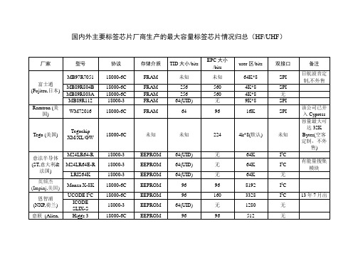
无
1280
无
意联(Alien,美国)
Higgs 3
18000-6C
EEPROM
96
96
512
无
EM(瑞士)
EM4325
18000-6C
EEPROM
48
352
3072
SPI
EM4233
18000-3
EEPROM
64(UID)
无
2K
无
英飞凌(Infineon,德国)
SRF 55V10S
18000-3
18000-6C
未知
未知
224
4k*8(默认)
未知
容量最大可达32K Bytes(空客定制,不外售)
意法半导体(ST,意大利&法国)
M24LR64-R
18000-3
EEPROM
64(UID)
无
64K
I2C
M24LR64E-R
18000-3
EEPROM
64(UID)
无
64K
I2C
有能量搜集模块
LRIS64K
FRAM
256
560
4K*8
SPI
MB89R803A
18000-6C
FRAM
256
560
4K*8
无
MB89R112
18000-3
FRAM
64(UID)
无
9K*8
SPI
Ramtron(美国)
WM72016
18000-6C
FRAM
64
96
16K
SPI
该公司已并入Cypress
Tego(美国)
英杰功率控制器通讯板说明书

PB20 通讯板 PROFIBUS
一 说明
PB20选件板通过PROFIBUS协议将装置与PROFIBUS网络连接起来。 PB20通讯板具备两个PROFIBUS接口,分别为1#口与2#口,通过板上拨码开关设置其地址与PPO模 式。当设置为不同地址时,可将两通讯接口接入同一PROFIBUS网络或不同网络;当地址设置相同时, 两通讯接口可在冗余的网络中运行。 订货时可指定为单通讯或双通讯:单通讯(PB20-1)、 双通讯(PB20-2)。
7.51 7.52 7.53 7.54 7.55 7.56 7.57 7.58 7.59 7.60 控制器单元 1#读对应
(5.51) (5.52) (5.53) (5.54) (5.55) (5.56) (5.57) (5.58) (5.59) (5.60) 控制器单元 2#写对应
7.61 7.62 7.63 7.64 7.65 7.66 7.67 7.68 7.69 7.70 控制器单元 2#读对应
通过 PB20 板上拨码开关设置通讯地址与 PPO 类型。 拨码值以二进制表示,当拨码在 ON 方向时表示 1,拨码在下方(数字方向)时表示 0。 地址拨码:地址拨码开关左边为二进制高位,右边为二进制低位;图 4 中 SW1 拨码为 00000011,
转换成十进制表示 3,因此 1#通讯口地址为 3。 PPO 拨码:拨码开关 SW2 和 SW4 第 2、3、4 位用二进制分别表示 1#与 2#通讯口的 PPO 类型。
PB20 通讯板 PROFIBUS 使用说明书
英杰电气有限公司为客户提供全方位的技术支持, 客户可与就近的英杰办事处或代理商联系。 内容如有改动,恕不另行通知!
目录
一 说明........................................................................................................................................................................1 二 技术参数................................................................................................................................................................1 三 安装........................................................................................................................................................................2 四 连接........................................................................................................................................................................2 五 地址与PPO类型设置............................................................................................................................................3 六 PROFIBUS-DP.....................................................................................................................................................4 七 参数区(PKW)读写 ..........................................................................................................................................6 八 过程数据区(PZD)读写....................................................................................................................................7 九 GSD文件 ...............................................................................................................................................................9 十 冗余功能................................................................................................................................................................9
瑛捷科技产品说明书

Features & Specifications• Available on FlexMove Aluminum Conveyors,FS (65 mm), FM (85 mm), FC (105 mm), FL (150 mm), FU (180 mm), and FV (260 mm)• Max. single product weight: 2.3 kg (5 lbs)• Max. product accumulation weight: 13.6 kg (30 lbs)• Max. conveyor speed: 50 m/min (164 ft/min)• Produces gap of approximately one product length• Pneumatic stop for pacing pucks or packages • Two Models:• Vertical Blade Stop; used in pairs as an alternating escapement for pacing round or rounded edge rectangular pucks• Horizontal Squeeze Stop; used in combination with Vertical Blade Stop for pacing product without rounded edges. Product must be able to withstand side squeeze pressure• Compatible with round or rectangular bottles, containers or pucks• UHMW face for non-marking contact surface • Includes flow controls with push-in air line connection• Requires photo sensors, pneumatic solenoid valves, wiring and programming• Rate depends on product size. Contact factory for detailsPUCK STOP MODULEDual Vertical Blade StopsHorizontal Squeeze Stop with Vertical Blade StopPuck stops alternate to pace productsVertical stop releases product and horizontal stop squeezes second to pace product141 mm[5.54 in]WW115 mm [4.52 in]50 mm [1.98 in]DimensionsTransforming Conveyor Automation© Dorner Mfg. Corp. 2021. All Rights Reserved. 851-954 0621Dorner – North & South AmericaDorner – U.S.A. Headquarters975 Cottonwood Ave Hartland, WI 53029, USA (800) 397-8664(262) 367-7600***************Dorner – Canada100-5515 North Service Road Burlington, Ontario L7L 6G6 Canada(289) 208-7306***************Dorner – Latin AmericaCarretera a Nogales #5297,Nave 11. Parque Industrial Nogales Zapopan, Jalisco C.P . 45222 Mexico+52.33.30037400****************************Dorner – EuropeDorner – GermanyKarl-Heinz-Beckurts-Straße 752428 Jülich, Germany+49 (0) 2461/93767-0 **********************Dorner – France8 rue des Frères Caudron 78140 Velizy-Villacoublay France+33 (0)1 84 73 24 27 **********************Dorner – Asia128 Jalan Permatang Damar Laut, Bayan Lepas 11960 Penang, Malaysia+604-626-2948|********************45 mm [1.78 in]W 91 mm[3.57 in]114 mm [4.48 in]W Vertical BladePart Number: 208169Horizontal SqueezePart Number: 208161141 mm 115 mm 50 mm [5.54 in]WW [4.52 in][1.98 in]。
英频杰读卡器培训资料

英频杰读卡器培训资料一、概述英频杰读卡器是一种用于读取和写入RFID标签和IC卡的设备。
它具有高速读取、高灵敏度、高可靠性等特点,被广泛应用于身份识别、门禁系统、物流管理等领域。
为了帮助用户更好地了解和使用英频杰读卡器,我们提供了本培训资料。
二、产品特点1、高速读取:英频杰读卡器支持高速读取RFID标签和IC卡,提高了数据传输速度和效率。
2、高灵敏度:读卡器具有高灵敏度,可以远距离读取RFID标签和IC卡,提高了使用便捷性。
3、高可靠性:英频杰读卡器采用高品质的硬件和软件,保证了长时间稳定运行和高可靠性。
4、多协议支持:读卡器支持多种协议,如ISO 、ISO 、Mifare等,可以与不同的系统兼容。
5、多种接口:英频杰读卡器提供多种接口,如USB、RS232、RJ45等,方便用户连接不同的设备。
6、远程管理:读卡器支持远程管理,用户可以通过网络对设备进行配置和管理。
7、易于集成:英频杰读卡器提供开放的API和文档,方便用户集成到自己的系统中。
三、使用方法1、连接设备:将英频杰读卡器通过USB或串口连接到计算机或网络中。
2、安装驱动:从官方网站下载并安装相应的驱动程序。
3、配置参数:根据实际需求配置读卡器的参数,如读取距离、读取速度等。
4、读取数据:在程序中调用读卡器的API函数,读取RFID标签和IC卡的数据。
5、处理数据:对读取到的数据进行处理和分析,如身份认证、数据统计等。
6、写入数据:如果需要,可以通过读卡器的API函数将数据写入RFID 标签和IC卡中。
7、维护保养:定期对读卡器进行维护保养,以保证其正常运行。
四、常见问题及解决方案1、读卡器无法连接:检查连接线是否完好,或者更换其他USB端口或线缆尝试连接。
2、读卡器无法识别:确认读卡器驱动程序已正确安装,并且设备已正确连接到计算机或网络。
检查设备是否开启并处于正常工作状态。
3、读取数据错误:检查RFID标签或IC卡是否完好,或者更换其他标签或IC卡尝试读取。
PAGlink微型充电器数据手册说明书

PAGlink Micro ChargerULTRA-COMPACT GOLD MOUNT TRAVEL CHARGER Array•The world’s smallest, single-position, multi-battery Gold Mount charger.•Charge up to 4 P AGlink Gold Mount batteries linked.•Designed for light travel - fits easily in your camera bag.•Charges 2 fully discharged 94Wh PAGlink batteries in 8 hours.•Power from a PSU (100-240V AC), a 12V vehicle battery or a 2A USB charger.© OCT 2017 PAG Ltd.PAG is the trademark of PAG Ltd.camera bag. It accepts 5-20V DC input, and can be powered from a variety of sources, making it the ideal travel charger.The Micro Charger will charge PAGlink Gold Mount batteries of any rated capacity, and from any state of charge, individually or linked. It can also be used for charging non-linking Gold Mount Li-Ion batteries manufactured by PAG.PAGlink is the first camera battery system that allows batteries to be linked for charging. At the end of a shoot, simply link your batteries and connect them to the charger. The next day, they will be fully charged and ready to go, without intervention.If you need power in a hurry, one fully discharged 94Wh battery will be 80% charged in approximately 3 hours. Twofully-discharged 94Wh PAGlink batteries will be fully-charged in approximately 8 hours.The charge status of each battery is shown on its individual display. The most-discharged batteries are given priority until all the batteries are in a similar state of charge; they are then fully-charged simultaneously. The charger features LEDindication of charging, charge completion, an absent battery and a faulty battery.PAG America is a division of the Carr Distribution Group:18 Center Street, Ramsey, NJ 07446, USA Sales Director: Bob Carr T: +1 631 300 8215E: ********************low-voltage DC. A power plug of your choice is included, which is interchangeable with other options that enable direct connection to worldwide AC outlets.The charger can also be powered from a 12V vehicle battery,Individual or linked charging, from any state of charge:PAGlink Gold Mount Batteries Models 9306 & 9313.Individual charging only:PAG Gold Mount Batteries Models 9310A, 9305A.Anton/Bauer Gold Mount Li-Ion Batteries.PAGlink Charging:The Micro Charger is designed for charging simultaneously up to 4 linked PAGlink batteries, of any rated capacity, from any state of charge.Recovery Charge:Automatically recovers a Li-Ion battery after shut down.Input: DC 5V to 20V. Connector: 2.1mm DC (PP90). Power Supply Unit: AC 100-240V ~ autoselected. Frequency 50-60Hz. Maximum power consumption 35W.Output: 1.5 Amps.Dimensions (charging shoe only) L x W x H:2.8" x 2.5” x 1.3” (72 x 63 x 33mm).Weight: 2.6oz (75g).Typical Battery Charging Times:Times are for fully-discharged batteries to fully-charged, when powering the charger using the Power Supply Unit. Charge times will be less if batteries are partially discharged.150Wh batteries will take 50% longer.AC POWER SUPPLY UNITCHARGER IN-CAR POWER LEADUSB POWER LEAD。
英杰克移动5000EFTPOS终端快速参考指南说明书
Quick Reference Guidefor Ingenico Move 5000 EFTPOS Terminal2Quick Reference Guide3Contactless Reader Menu Screenscroll up on the touch screen, or press the menu item number on the keypadCancelPress the red CANCEL key Clear entryCard InsertPrinterEnter Key and Power On Press the green ENTER keyPower OffRemove the terminal from any power source. Press and hold the Func and yellow CLEAR keys togetherEnter the sale amount from idle/home screen and press ENTERAsk the customer to TAP, INSERT or SWIPE their cardWhere prompted by the terminal, ask the customer to select their account type: Cheque, Savings or CreditWhen prompted, allow the customer to enter their PIN and press ENTERNote: Contactless cards do not require a PIN or signature for amounts under $100 Once approved, remove the card if inserted and press Y es to print a customer receipt, if requestedPress MENU key on the home screen, press 2 for Print, then 1Last transaction receipt:Press 1 for Last to reprint receipt for the last transactionSpecific receipt from the current settlement period:Press 2 for InvoicePress MENU key on the home screen, press 1 for Transactions, then 3 for Refund Enter your refund password and press ENTERAsk the customer to INSERT or SWIPE their cardAsk the customer to select their account type: Cheque, Savings or CreditOn PIN prompt, ask the customer to press ENTER to print the refund receipt to sign Note: Even if a PIN is entered, a signed receipt will still be required4 Quick Reference GuideThis will print a list of all transactions processed since the Last SettlementPress MENU key on the home screen, press 2 for Print, press 2 for Reports, then press 1for AuditPress MENU key on the home screen, and press 3 for BatchPre-settlement totals:Press 4 for Batch TotalsNote:T his will print the total value of transactions that have occurred since the Last SettlementPress Y es to print a Transaction List, if requiredLast Settlement totals:Press 2 for Last SettlementNote: This will print the total value of transactions in the Last Settlement periodView Batch details on the screen:Press 3 for Review BatchQuick Reference Guide 56 Quick Reference GuideInstalling the Paper RollStep 1Open the paper compartment by lifting the catch located at the rear of the terminal and pull the cover to the rear of the terminal.Step 2Place the paper roll into the compartment, ensuring that the paper protrudes over the top of the roll (if the paper protrudes from underneath the roll it has been inserted incorrectly). Pull the paper up toward the top of the terminal. Hold the paper and close the cover. Press simultaneously on both upper corners of the contactless landing zone, until it clips into position. If required, pressthe Feed key on the keypad to advance the paper.5For Display Transaction Totals, continue to press ENTER to view all totals, such as Sales, Refunds, Tips and so on 8View Batch Number21View Transaction by Invoice NumberAdditional FunctionsPress the Func key, the Function Number and ENTER to perform the following PIN pad functions:TroubleshootingHardware FaultsThe terminal does not turn on•C heck the battery (is discharged, is connected)•A full discharged battery can take a long charging time to recover•C onnect terminal-to-terminal power supply or put it on the powered base and check if the battery symbol is flashing or moving (= battery charging)Cards not read•C heck that the magnetic card is swiped correctly (with magnetic band onterminal side)•S wipe again the card with the magnetic stripe movement constant and rapid•V erify that the magnetic stripe is not damaged, grooved or cracked•M ake sure you have inserted correctly the smart card into the smart card reader and removed the card only after the transaction is performedThe receipt has not printed•C heck the presence and proper positioning of the paper roll possibly adjust the paper roll following the instructions in this manual•C heck the type of paper used (thermal paper must be used)Quick Reference Guide 78Quick Reference Guide 9Note: Graphic will only print on the customer copy of the receipt.ReceiptExample of the purchase transaction recordY our business name and addressDate and time of transactionY our Merchant ID number Y our Terminal ID numberAccount typeTruncated card number Expiry date Total amountTransaction approved/declined© 2020 Fiserv, Inc. or its affiliates. All rights reserved. Fiserv is a registered trademark of Fiserv, Inc. Other products referenced in this material may be trademarks or registered trademarks of their respective companies. 633964 2020-7Fiserv, Inc.30th Floor,100 Mount Street, North Sydney, NSW 2060, Australia********************************Visit the “Client Support” page on our websiteA comprehensive user guide to the EFTPOS Terminal can be downloaded from our website. The site is equipped to keep you up to date with news, forms and guides, security and fraud prevention information, access to our online reporting tool and much more.Or call 1800-243-444Our dedicated team of experts can assist you over the phone 24/7 with questions, problem resolution, and extra training. Keep your Merchant ID number handy when you call to help speed up your enquiry.。
Impinj-D500桌面式UHF读写器操作手册

Impinj桌面式UH F读写器操作手册第1章引言该读写器是美国Impi nj(英频杰) 公司设计开发,内置小型线极化天线,支持EPCglobal UHF Class1 Gen 2 / ISO 18000-6C国际标准。
产品兼容性好,读写速度快,操作便捷,性价比高,适用于UHF频段电子标签的发卡应用,广泛应用于物流仓储、门禁管理、车辆管理及资产管理等领域。
本文档用于说明读写器U SB驱动程序和Impinj D500软件的使用操作手册。
1.1 系统功能◆读取单个电子标签中的I D号或EP C码;◆对电子标签中用户数据区数据进行读写;◆良好的防冲撞性能,可同时读取多个电子标签中的ID号或EPC码;◆提供USB接口进行数据通信和对发卡器供电;◆LED灯指示读写器的电源情况以及工作状况;1.2 发卡器所需附件D500桌面式发卡器需要个人计算机系统及发卡器接口软件(USB驱动)和读写器演示软件(IMPINJ-D500)才能使用。
个人计算机系统的最低配置要求是:◆有USB接口◆存储器容量:128M或以上内存◆PIII400或以上◆Window s 2000/xp 或win 7软件平台◆需.net framework 2.0支持。
第2章安装本章介绍D500桌面式读写器的U SB驱动程序和IMP INJ-D500软件的安装。
(以下以WIN 7系统为例)2.1 USB驱动程序安装点击“计算机”属性,出现下图界面。
点击“设备管理器”在“其他设备”显示有未安装的驱动程序,右击扫描安装驱动,指定搜索安装的文件夹,系统自动搜索安装,下图为成功安装后(通用串行总线控制器——UsbHar ve.Sys for Impinj RFID MAC)。
此时USB驱动程序成功安装。
英频杰(Impinj)推出Indy R500读写器芯片

卡 ,然 后 储 存柜 进 行
队 、执法机 构和其他机 构的武器装备 检查 ,看看这个军官 的安全。
一
是否被授权使 用泰瑟
开始安装 的时候 ,警察部门使 枪 。若 授 权 了 ,这 套
用这套系统里的装有R I 的储存柜来 系统会通过一系列的 FD
监测和跟踪泰 瑟枪 。每把 泰瑟枪 都贴 法律 和程序指示指导这个军官 ,电子 每件 武器提 供一个完整的记录。它 着一个高频 的T AGS i 7  ̄ 磁 签署泰 瑟枪 ,然后系统发出信号使其 供 了 每件 武 器 完 整 的 历 史 记 录 ,为 YSAro3 0 x 盘模块 的R I 标签 ,并使用T FD AGS 中一个抽屉打开。 YS
・减 少分散 阅读 的I Q解调 器。
・抵 消提供 接收 器的灵敏 度 的有 源
、
近 日,英 国的一个警察部门正
在 试 行 一 套 基 于 RF D的 武 器 I
当有军官需要泰 瑟枪时 ,他在 储存柜
跟踪解决方案 ,这个方 案由T AGS 上的读写器前出示I YS D
公 司 和 RF P 限公 司 开发 ,可 保证 军 I有
Me i 0 2O M F D 写器和 安 装 doP 3 E R I 读 理 者 生 成 审 计 报 告 ,防 止 把 武器 发 左
这 套系统 名为智能抽 屉军械库系 给未 经授权 的人员 ,提 高了武器 的皇 统 ,自动记 录武器 的发放 和归还 ,为 全性 。
在储存柜上的天线来监控。
写器 ,用于零售 、制造业 、资产跟是 和访 问控制。R 0 n yD v l me 50Id e eo I p
Pa om ( 50Id开 发平 台 ,包含 lf t r R 0 y n
OctaneSdkQuickReference英频杰(Impinj)读写器sdk快速使用参考
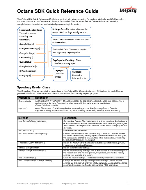
The OctaneSdk Quick Reference Guide is organized into tables covering Properties, Methods, and Callbacks for the main classes in the OctaneSdk. See the OctaneSdk Tutorial Workbook or Online Reference Guide for complete class descriptions and detailed programming information.Speedway Reader ClassThe Speedway Reader class is the main class in the OctaneSdk. Create instances of this class for each Reader you wish to control. Inherit from this class to add reader functionality to your program.TagReport ClassThe TagReport class contains tag information obtained by the Reader. Access TagReport instances through the SpeedwayReader class methods, callbacks, and events.Tag ClassThe Tag class contains the information obtained by the Reader for a specific EPC value. Access Tag instances through the TagReport class.Settings ClassThe Settings class carries the information on the readers RFID settings (configuration). Access Settings class instances through the SpeedwayReader class methods.Status ClassThe Status class allows access to the Reader’s status cached or in real time. Access Status class instances through the SpeedwayReader class methods.FeatureSet ClassThe FeatureSet class allows access to the Reader, model, and regulatory region specific differences. Access FeatureSet instances through the SpeedwayReader class methodsAdditional SupportThe Impinj Learning Center provides application notes and code samples. Impinj Support provides technical support.。
英频杰读卡器培训资料

20 | © 2013
FastIDTM
• 在固件升级过程中可恢复 – 操作稳定性提高 – 可以实现远程的固件升级 • 支持现有接口 – USB/UART – 数据接口兼容 – 不需要额外的硬件
• 故障安全Bootloader更可靠
23 | © 2013
固件升级历史
• V2.6 – 最新版本 – 更详尽的盘点数据
• V2.4.2 – Monza芯片支持(FastID、TagFocus) – Fail Safe Boot Loader • V2.3.0 – 支持 LBT – 支持R2000, R1000, R500
• V2.2.0 – 支持R2000,R1000
24 | © 2013
RF 基础知识
25 | © 2013
射频波
美国 = 300/915MHz ~ 33cm (~13”) 中国 = 300/920MHz ~ 32cm
26 | © 2013
UHF RFID工作频段
• UHF (860 – 960 MHz)
– 天线的发射特性变化
• 天线生产一致性 • 外部环境变化
– 在全功率发射时天线发射增加 – 特殊的天线如近场天线设计
• 一般都会有很高的反射特性
– 接收灵敏度提高大约
• Indy R2000是目前市场上唯一一款具有载波抑制能 力的读写器芯片
5
|©
2013
载波抑制框图
Impinj读写器使用说明 r420

Impinj读写器使用说明V1.0.0杭州紫钺科技有限公司2011年04月尊敬的客户,你好!首先非常感谢您对Impinj产品的支持!下面我们来看看如何快速、有效地连接与使用Impinj读写器,在这里我们以Impinj Revolution系列为例,(以下简称IPJ R)希望您使用愉快!一: 硬件连接读写器接口首先我们要了解下读写器的各种接口,如下图所示硬件的准备Impinj读写器一台、电源适配器一个、天线与馈线若干、直连网线2条、交叉网线一条、PC一台。
软件的准备需要在您的PC上安装Bonjour打印插件和MultiReader 程序,如下图所示完成以上安装,下面我们就来连接设备,这里我们通过TCP/IP的方式进行连接;IPJ R读写器可以通过与PC用网线直连的方式和通过网络交换机连接两种方式,这里我们以和PC直连的方式连接。
将PC本地的IP地址设为自动获取,包括自动获取DNS:二: 查找和更改读写器的IP首先在读写器外壳上找到其MAC地址,找到最后3位,如00:16:25:10:3E:C0中的10,3E,C0。
读写器的hostname为Speedwayr-XX-XX-XX,其中XX 为MAC地址后3位,如Speedwayr-10-3E-C0,下面以上述MAC地址为例。
查找读写器IP打开CMD命令,输入ping speedwayr-10-3E-C0.local,如图所示连接成功后,会显示产品目前的IP地址,如图所示更改读写器IP进入telnet下,如图所示然后使用open指令: o speedwayr-10-3E-C0.local.如图所示进入后,输入账号root 密码impinj,注意密码为不可见. 如图所示输入config network ip, 如图所示此命令下可以设置读写器IP的获取方式,其中dynamic 为将读写器设置成动态IP,static为将读写器设置一个固定IP,如图所示设置成功后退出即可。
美国英频杰公司

美国英频杰(Impinj)股份有限公司美国英频杰(Impinj®)公司是全球最领先的超高频Gen 2 RFID解决方案供应商。
基于公司的先进技术和与业界伙伴的紧密合作,创造出应用广泛的产品和解决方案,包括高性能标签芯片、读写器、读写器芯片、软件、天线与系统集成。
英频杰(Impinj®)拥有世界性能最好的读写器Speedway ,读写器芯片Indy和标签芯片Monza全球市场占有率第一,英频杰(Impinj®)产品品质已成为公认的行业标准。
在库存管理、资产跟踪、认证与序列化等全球垂直市场应用领域,英频杰(Impinj®)为客户提供了前所未有的性能、集成度与成本效益解决方案。
英频杰(Impinj®)公司,由Carver Mead 博士和Chris Diorio 博士共同创建于2000年5月,迄今已融资超过1亿1千万美元。
Carver Mead 博士,2003年被授予国家技术奖章,Chris Diorio 博士是UHF Gen 2 标准的驱动者,华盛顿大学副教授,用RFID技术彻底变革了供应链、医药等行业应用。
2011年公司成绩亮点:1. 在中国市场全面推广读写器Speedway Revolution。
此款读写器,运用英频杰(Impinj®)全新专利技术Autopilot,自动调节最佳工作状态,重新定义了高性能,简单易用,可靠性以及低成本的业界新标准,赢得市场客户的喜爱。
2. 标签芯片Monza 4 系列不断创新销售记录。
最新推出Monza5芯片。
作为业界最灵活、最佳性能的标签芯片,最新的Monza 4 系列以更高的读写可靠度、真正的全方位天线设计支持、独一无二的保密性和更大内存,不断创新销售记录,累计销售数量突破十亿片,拥有全球70%的市场份额。
同时impinj最新推出了Monza5芯片,实现了单品级应用的标签最低应用成本。
Monza 5的写入灵敏性是其他同类芯片的四到六倍,显著提高了写入的可靠性以及编码速度和锁定速度。
- 1、下载文档前请自行甄别文档内容的完整性,平台不提供额外的编辑、内容补充、找答案等附加服务。
- 2、"仅部分预览"的文档,不可在线预览部分如存在完整性等问题,可反馈申请退款(可完整预览的文档不适用该条件!)。
- 3、如文档侵犯您的权益,请联系客服反馈,我们会尽快为您处理(人工客服工作时间:9:00-18:30)。
此手册包含Impinj英频杰第二代超高频RFID系列产品的相关订购信息,包括读写器、读写器天线、维护服务及读写器芯片、读写器开发套件等。
有关产品的具体描述和数据信息,请登录impinj中国区代理杭州紫钺科技有限公司网站查询。
Readers读写器peedway?读写器,以业界领先的最佳性能和可靠保证,在市场上久负盛名。
在此基础上,全新的Speedway?Revolution读写器,凭借专利技术Autopilot,带来更加卓越灵活的性能,并且简单易用,通过以太网供电(PoE)降低成本,广泛适用于各种集成解决方案。
ReadersAntennas读写器天线
Impinj英频杰提供各种规格和频率特性的读写器天线。
技术支持400-672-2818。
总体上,FCC指902-928兆赫的超高频频率范围,ETSI指865-868兆赫和860-960兆赫的的超高频频率范围,LHPZ指左旋偏振,RHP指右旋偏振。
IndyReaderChips读写器芯片Indy?RFID读写器芯片,产品线包括基于Intel 公司获奖技术的Indy?RFID读写器芯片系列。
高度集成的IndyRFID读写器芯片与其支持软件是整个第二代超高频RFID读写器系列的核心,支持从近距离的嵌入式模块到远距离门式读写器的广泛应用。
订购信息:在通常情况下,供货期为4—6周,具体根据产品类型和数量而定。
确切供货期将在订单确认函(theorderconfirmation)中注明。
Impinj致力于提供具有价格竞争力的系列产品,并保留修改价格的权利,请联系impinj中国代理杭州紫钺科技有限公司了解最新价格。
