MEMORY存储芯片STM32F103RCT6中文规格书
MEMORY存储芯片GD32F103RCT6中文规格书
3.Functional description3.1. ARM® Cortex™-M3 coreThe Cortex™-M3 processor is the latest generation of ARM®processors for embeddedsystems. It has been developed to provide a low-cost platform that meets the needs of MCUimplementation, with a reduced pin count and low-power consumption, while deliveringoutstanding computational performance and an advanced system response to interrupts.⏹32-bit ARM®Cortex™-M3 processor core⏹Up to 108 MHz operation frequency⏹Single-cycle multiplication and hardware divider⏹Integrated Nested Vectored Interrupt Controller (NVIC)⏹24-bit SysTick timerThe Cortex™-M3 processor is based on the ARMv7 architecture and supports both Thumband Thumb-2 instruction sets. Some system peripherals listed below are also provided byCortex™-M3:⏹Internal Bus Matrix connected with I-Code bus, D-Code bus, System bus, PrivatePeripheral Bus (PPB) and debug accesses.⏹Nested Vectored Interrupt Controller (NVIC).⏹Flash Patch and Breakpoint (FPB).⏹Data Watchpoint and Trace (DWT).⏹Instrumentation Trace Macrocell (ITM).⏹Embedded Trace Macrocell (ETM).⏹Serial Wire JTAG Debug Port (SWJ-DP).⏹Trace Port Interface Unit (TPIU).⏹Memory Protection Unit (MPU).3.2. On-chip memory⏹Up to 3072 Kbytes of Flash memory⏹Up to 96 Kbytes of SRAMThe ARM®Cortex™-M3 processor is structured in Harvard architecture which can useseparate buses to fetch instructions and load/store data. 3072 Kbytes of inner Flash and 96Kbytes of inner SRAM at most is available for storing programs and data, both accessed (R/W)at CPU clock speed with zero wait states.The Table 2-4. GD32F103xx memory mapshows the memory map of the GD32F103xx series of devices, including code, SRAM,peripheral, and other pre-defined regions.3.3. Clock, reset and supply management⏹Internal 8 MHz factory-trimmed RC and external 4 to 16 MHz crystal oscillator⏹Internal 40 KHz RC calibrated oscillator and external 32.768 KHz crystal oscillator⏹Integrated system clock PLL⏹ 2.6 to 3.6 V application supply and I/Os⏹Supply Supervisor: POR (Power On Reset), PDR (Power Down Reset), and low voltagedetector (LVD)The Clock Control unit provides a range of frequencies and clock functions. These include anInternal 8M RC oscillator (IRC8M), a High Speed crystal oscillator (HXTAL), a Low SpeedInternal 40K RC oscillator (IRC40K), a Low Speed crystal oscillator (LXTAL), a Phase LockLoop (PLL), a HXTAL clock monitor, clock prescalers, clock multiplexers and clock gatingcircuitry. The frequency of AHB, APB2 and the APB1 domains can be configured by eachprescaler. The maximum frequency of the AHB, APB2 and APB1 domains is 108 MHz/108MHz/54 MHz. See Figure 2-8. GD32F103xx clock tree for details.GD32F10x Reset Control includes the control of three kinds of reset: power reset, systemreset and backup domain reset.The system reset resets the processor core and peripheralIP components except for the SW-DP controller and the Backup domain.Power-on reset(POR) and power-down reset (PDR) are always active, and ensures proper operation startingfrom/down to 2.6 V. The device remains in reset mode when V DD is below a specifiedthreshold. The embedded low voltage detector (LVD) monitors the power supply, comparesit to the voltage threshold and generates an interrupt as a warning message for leading theMCU into security.Power supply schemes:⏹V DD range: 2.6 to 3.6 V, external power supply for I/Os and the internal regulator.Provided externally through V DD pins.⏹V SSA, V DDA range: 2.6 to 3.6 V, external analog power supplies for ADC, reset blocks,RCs and PLL. V DDA and V SSA must be connected to V DD and V SS, respectively.⏹V BAT range: 1.8 to 3.6 V, power supply for RTC, external clock 32 KHz oscillator andbackup registers (through power switch) when V DD is not present.3.4. Boot modesAt startup, boot pins are used to select one of three boot options:⏹Boot from main flash memory (default)⏹Boot from system memory⏹Boot from on-chip SRAMThe boot loader is located in the internal boot ROM memory (system memory). It is used toreprogram the Flash memory by using USART0 (PA9 and PA10), if devices areGD32F103xF/G/I/K, USART1 (PA2 and PA3) is also available for boot functions. It also can453.5. Power saving modesThe MCU supports three kinds of power saving modes to achieve even lower powerconsumption. They are sleep mode, deep-sleep mode, and standby mode.These operatingmodes reduce the power consumption and allow the application to achieve the best balancebetween the CPU operating time, speed and power consumption.⏹Sleep modeIn sleep mode, only clock of Cortex™-M3 is off. All peripherals continue to operate andany interrupt/event can wake up the system.⏹Deep-sleep modeIn deep-sleep mode, all clocks in the 1.2V domain are off, and all of IRC8M, HXTAL andPLLs are disabled. Only the contents of SRAM and registers are retained. Any interruptor wakeup event from EXTI lines can wake up the system from the deep-sleep modeincluding the 16 external lines, the RTC alarm, the LVD output, USB Wakeup and EthernetWakeup. When exiting the deep-sleep mode, the IRC8M is selected as the system clock.⏹Standby modeIn standby mode, the whole 1.2V domain is power off, the LDO is shut down, and all ofIRC8M, HXTAL and PLL are disabled.The contents of SRAM and registers (exceptBackup registers) are lost. There are four wakeup sources for the Standby mode,including the external reset from NRST pin, the RTC alarm, the FWDGT reset, and therising edge on WKUP pin.3.6. Analog to digital converter (ADC)⏹12-bit SAR ADC⏹Up to 1 MSPS for 12-bit resolution⏹Analog input signal voltage range: V SSA to V DDA (2.6 to 3.6 V)⏹Temperature sensorUp to three 12-bit multi-channel ADCs are integrated in the device. Each has a total of up to21 multiplexed external channels. An analog watchdog block can be used to detect thechannels, which are required to remain within a specific threshold window. A configurablechannel management block of analog inputs also can be used to perform conversions insingle, continuous, scan or discontinuous mode.The ADCs can be triggered from the events generated by the general level 0 timers (TIMERx)or the advanced timers (TIMER0 and TIMER7) with internal connection. The temperaturesensor generates a voltage that varies linearly with temperature. The analog supply voltageV DDA can vary from 2.6 V to 3.6 V. The output voltage of temperature sensor is internallyconnected to the ADC_IN16 input channel.3.7. Digital to analog converter (DAC)⏹Two 12-bit DACs with independent output channels⏹8-bit or 12-bit mode in conjunction with the DMA controllerThe two 12-bit buffered DACs are used to generate variable analog outputs. The DACchannels can be triggered by the timer or EXTI with DMA support.In dual DAC channeloperation, conversions could be done independently or simultaneously. The maximum outputvalue of the DAC is V REF+.3.8. DMA⏹7 channel DMA0 controller and 5 channel DMA1 controller⏹Peripherals supported: Timers, ADC, SPIs, I2Cs, USARTs, DAC, I2S and SDIOThe direct memory access (DMA) controllers provide a hardware method of transferring databetween peripherals and/or memory without intervention from the CPU, thereby freeing upbandwidth for other system functions. Three types of access method are supported:peripheral to memory, memory to peripheral, memory to memory.Each channel is connected to fixed hardware DMA requests. The priorities of DMA channelrequests are determined by software configuration and hardware channel number.Transfersize of source and destination are independent and configurable.3.9. General-purpose inputs/outputs (GPIOs)⏹Up to 112 fast GPIOs, all mappable on 16 external interrupt lines⏹Analog input/output configurable⏹Alternate function input/output configurableThere are up to 112 general purpose I/O pins (GPIO), named PA0 ~ PA15, PB0 ~ PB15, PC0~ PC15, PD0 ~ PD15, PE0 ~ PE15, PF0 ~ PF15 and PG0 ~ PG15 for the device to implementlogic input/output functions. Each GPIO port has related control and configuration registers tosatisfy the requirements of specific applications. The external interrupt on the GPIO pins ofthe device have related control and configuration registers in the Interrupt/event ControllerUnit (EXTI). The GPIO ports are pin-shared with other alternative functions (AFs) to obtainmaximum flexibility on the package pins. The GPIO pins can be used as alternative functionalpins by configuring the corresponding registers regardless of the AF input or output pins. Eachof the GPIO pins can be configured by software as output (push-pull or open-drain), input,peripheral alternate function or analog mode. Each GPIO pin can be configured as pull-up,pull-down or no pull-up/pull-down. All GPIOs are high-current capable except for analog mode.3.10. Timers and PWM generation⏹Up to two 16-bit advanced timer (TIMER0 & TIMER7), ten 16-bit general timers, and two16-bit basic timer (TIMER5 & TIMER6)⏹Up to 4 independent channels of PWM, output compare or input capture for each andexternal trigger input⏹16-bit, motor control PWM advanced timer with programmable dead-time generation foroutput match⏹Encoder interface controller with two inputs using quadrature decoder⏹24-bit SysTick timer down counter⏹ 2 watchdog timers (Free watchdog timer and window watchdog timer)The advanced timer (TIMER0 & TIMER7) can be seen as a three-phase PWM multiplexedon 6 channels. It has complementary PWM outputs with programmable dead-time generation.It can also be used as a complete general timer. The 6 independent channels can be usedfor。
STM32F103增强型中文数据手册

数据手册STM32F103x6STM32F103x8 STM32F103xB 增强型,32位基于ARM核心的带闪存、USB、CAN的微控制器7个16位定时器、2个ADC 、9个通信接口功能■内核:ARM 32位的Cortex™-M3 CPU− 72MHz,1.25DMips/MHz(Dhrystone2.1),0等待周期的存储器−单周期乘法和硬件除法■存储器−从32K字节至128K字节的闪存程序存储器−从6K字节至20K字节的SRAM■时钟、复位和电源管理− 2.0至3.6伏供电和I/O管脚−上电/断电复位(POR/PDR)、可编程电压监测器(PVD)−内嵌4至16MHz高速晶体振荡器−内嵌经出厂调校的8MHz的RC振荡器−内嵌40kHz的RC振荡器− PLL供应CPU时钟−带校准功能的32kHz RTC振荡器■低功耗−睡眠、停机和待机模式−V BAT为RTC和后备寄存器供电■2个12位模数转换器,1us转换时间(16通道) −转换范围:0至3.6V−双采样和保持功能−温度传感器■DMA−7通道DMA控制器−支持的外设:定时器、ADC、SPI、I2C和USART■多达80个快速I/O口− 26/37/51/80个多功能双向5V兼容的I/O口−所有I/O口可以映像到16个外部中断■调试模式−串行线调试(SWD)和JTAG接口■多达7个定时器−多达3个16位定时器,每个定时器有多达4个用于输入捕获/输出比较/PWM或脉冲计数的通道− 16位6通道高级控制定时器−多达6路PWM输出−死区控制、边缘/中间对齐波形和紧急制动−2个看门狗定时器(独立的和窗口型的)−系统时间定时器:24位自减型■多达9个通信接口−多达2个I2C接口(SMBus/PMBus)−多达3个USART接口,支持ISO7816,LIN,IrDA接口和调制解调控制−多达2个SPI同步串行接口(18兆位/秒)− CAN接口(2.0B 主动)− USB 2.0全速接口■ECOPACK®封装(兼容RoHS)表一 器件列表参考基本型号STM32F103x6 STM32F103C6,STM32F103R6,STM32F103T6STM32F103x8 STM32F103C8, STM32F103R8,STM32F103V8, STM32F103T8 STM32F103xB STM32F103RB, STM32F103VB,STM32F103C8数据手册1 介绍 (3)2 规格说明 (3)2.1 器件一览 (4)2.2 概述 (5)3 管脚定义 (11)4 存储器映像 (19)5 电气特性 (20)6 封装参数 (20)7 订货代码 (20)7.1 后续的产品系列 (21)8 版本历史 (21)附录A 重要提示 (22)A.1PD0和PD1在输出模式下 (22)A.2ADC自动注入通道 (22)A.3ADC的混合同步注入+交替模式 (22)A.4ADC通道0 (22)1介绍本文给出了STM32F103xx增强型的订购信息和器件的机械特性。
STM32F103RET6中文资料_数据手册_参数
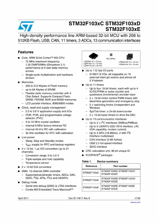
STM32F103RCT6使用说明

STM32开发板使用手册风帆 STM32开发板是风帆电子为初学者学习STM32 Cortex M3 系列ARM 而设计的学习板。
以STM32F103RCT6芯片为核心,配套寸彩色TFT屏模块,板载UART、USB、ADC电压调节、按键、JTAG接口、彩屏接口、流水灯、SD卡接口、IO引出口等多种硬件资源。
v1.0 可编辑可修改JTA2个LEDGPIOA引出1O USB 串口DS10B 20预HS0038红外接红外温度传感器连接GPIOB@C引出IO OLED@LCD 共用接口STM32F103寸LCD 接485芯片 RS485接口 1:A; 3:BNRF24L01W25Q16 FLASHSD 卡接口(在JF24C 模块预留GPIOC @D 引出IO蜂鸣器跳PS/2鼠标键盘三个按键: WAKEUPRESET按键Rs232电源开关 USB 接口 电源指自恢复保MAX232电源芯24c02、5V 电源输出; 线序为: GND/GND/5V BOOT 设置 线序为:GND /GND BOOT1/BOOT0此板子不管硬件还是软件完全无缝接兼容正点原子的MINSTM32,并对MINSTM32进行了完美的升级,让我们用最少的钱做更多的事,具体升级的部分包括:1、C PU的升级利用ST意法半导体的CPU兼容性强的优点,此板采用比STM32F103RBT6性能更强、且完全兼容的的STM32F103RCT6升级CPU,把完美的MINNI STM板子的功能发挥到极致,具体2个CPU的主要资源对比如下:可以看出,FLASH增加了一倍,达到256K,RAM也增加了1倍,让我们不用再为FLASH\RAM小而烦恼,使我们的存储空间更为强大;增加了一个16位普通IC/OC/PWM),2个16位基本(IC/OC/PWM),1个STI,2个USART,这里比STM32F103RB还多了一个DAC通道,这个STM32F103RB是没有的2、由于STM32F103RCT6有多达5个USART,因此在这个开发板上我们增加了个RS485芯片,我们可以进行485通信;3、STM32F103RCT6有多达5个USART,其中有3个支持7816协议,可以实现智能卡的设计,对于想学习、研究、设计智能一卡通的同学最好的选择;4、STM32F103RCT6比STM32F103RBT6多一个DAC通道,我们可以用杜邦线从我们的引出IO引脚上引出引脚,进行学习、设计。
stm32f103中文资料

深圳市迪通科技有限公司 TEL:0755-83312947 83313941 83317488FAX:0755-83311568
STM32F103x8, STM32F103xB数据手册
目录
1 介绍......................................................................................................................................................... 4 2 规格说明.................................................................................................................................................. 5
stm32f103中文手册[1]
![stm32f103中文手册[1]](https://img.taocdn.com/s3/m/f9dc370982c4bb4cf7ec4afe04a1b0717fd5b3fc.png)
STM32F103中文手册概述32位ARM® Cortex®-M3内核,最高运行频率72 MHz从16 KB到1 MB的闪存,从6 KB到96 KB的SRAM从36到144个引脚的不同封装,支持LQFP、BGA、TFBGA、UFBGA和V FQFPN等从1.65 V到3.6 V的宽电源电压范围,支持低功耗模式和电池供电从-40°C到+105°C的工作温度范围多达11个通信接口,包括3个USART、2个UART、2个I2C、2个SPI、1个CAN和1个USB 2.0全速多达15个定时器,包括7个16位通用定时器、2个16位基本定时器、2个16位高级定时器、2个32位定时器和2个看门狗定时器多达3个12位模数转换器(ADC),每秒可采样1.2 M次两路12位数模转换器(DAC)多达80个外部中断/事件源多达112个GPIO端口,支持5 V耐压CRC计算单元,用于检测数据传输错误实时时钟(RTC),支持日历功能和闹钟功能嵌入式内存保护单元(MPU),用于增强应用程序安全性嵌入式调试支持,包括串行线调试(SWD)和JTAG接口7层DMA控制器,支持所有外设数据传输可选的双银行闪存模式,支持实时软件更新存储器映射STM32F103系列单片机的存储器映射如下图所示:![存储器映射]代码区:包括闪存和系统存储器。
闪存用于存储用户程序代码和数据。
系统存储器用于存储引导加载程序(bootloader)和设备标识符。
SRAM区:包括SRAM1和SRAM2。
SRAM1用于存储用户程序数据和堆栈。
SRAM2用于存储备份寄存器和备份域。
外设区:包括APB1外设、APB2外设和AHB外设。
APB1外设和APB2外设是通过两个高速总线矩阵连接到内核的低速外设。
AHB外设是通过一个高速总线矩阵连接到内核的高速外设。
外部设备区:包括FSMC区域、NOR/PSRAM区域和NAND/CF区域。
STM32F103增强型中文数据手册

数据手册STM32F103x6STM32F103x8 STM32F103xB 增强型,32位基于ARM核心的带闪存、USB、CAN的微控制器7个16位定时器、2个ADC 、9个通信接口功能■内核:ARM 32位的Cortex™-M3 CPU− 72MHz,1.25DMips/MHz(Dhrystone2.1),0等待周期的存储器−单周期乘法和硬件除法■存储器−从32K字节至128K字节的闪存程序存储器−从6K字节至20K字节的SRAM■时钟、复位和电源管理− 2.0至3.6伏供电和I/O管脚−上电/断电复位(POR/PDR)、可编程电压监测器(PVD)−内嵌4至16MHz高速晶体振荡器−内嵌经出厂调校的8MHz的RC振荡器−内嵌40kHz的RC振荡器− PLL供应CPU时钟−带校准功能的32kHz RTC振荡器■低功耗−睡眠、停机和待机模式−V BAT为RTC和后备寄存器供电■2个12位模数转换器,1us转换时间(16通道) −转换范围:0至3.6V−双采样和保持功能−温度传感器■DMA−7通道DMA控制器−支持的外设:定时器、ADC、SPI、I2C和USART■多达80个快速I/O口− 26/37/51/80个多功能双向5V兼容的I/O口−所有I/O口可以映像到16个外部中断■调试模式−串行线调试(SWD)和JTAG接口■多达7个定时器−多达3个16位定时器,每个定时器有多达4个用于输入捕获/输出比较/PWM或脉冲计数的通道− 16位6通道高级控制定时器−多达6路PWM输出−死区控制、边缘/中间对齐波形和紧急制动−2个看门狗定时器(独立的和窗口型的)−系统时间定时器:24位自减型■多达9个通信接口−多达2个I2C接口(SMBus/PMBus)−多达3个USART接口,支持ISO7816,LIN,IrDA接口和调制解调控制−多达2个SPI同步串行接口(18兆位/秒)− CAN接口(2.0B 主动)− USB 2.0全速接口■ECOPACK®封装(兼容RoHS)表一 器件列表参考基本型号STM32F103x6 STM32F103C6,STM32F103R6,STM32F103T6STM32F103x8 STM32F103C8, STM32F103R8,STM32F103V8, STM32F103T8 STM32F103xB STM32F103RB, STM32F103VB,STM32F103C8数据手册1 介绍 (3)2 规格说明 (3)2.1 器件一览 (4)2.2 概述 (5)3 管脚定义 (11)4 存储器映像 (19)5 电气特性 (20)6 封装参数 (20)7 订货代码 (20)7.1 后续的产品系列 (21)8 版本历史 (21)附录A 重要提示 (22)A.1PD0和PD1在输出模式下 (22)A.2ADC自动注入通道 (22)A.3ADC的混合同步注入+交替模式 (22)A.4ADC通道0 (22)1介绍本文给出了STM32F103xx增强型的订购信息和器件的机械特性。
stm32f103中文手册[7]
![stm32f103中文手册[7]](https://img.taocdn.com/s3/m/38586d2658eef8c75fbfc77da26925c52cc59127.png)
stm32f103中文手册1. 概述stm32f103是一款高性能、低功耗、高集成度的32位微控制器,基于ARM Cortex-M3内核,支持Thumb-2指令集,具有72MHz的主频和64KB至512KB的闪存。
stm32f103具有丰富的外设资源,包括多种通信接口、定时器、模数转换器、DMA控制器、触摸感应控制器等,能够满足各种复杂的应用需求。
stm32f103还具有多种低功耗模式,能够实现动态电源管理,降低系统功耗。
stm32f1 03采用多种封装形式,适用于不同的应用场合。
2. 引脚定义stm32f103的引脚定义如图1所示。
stm32f103的引脚分为四类:电源引脚、复位引脚、晶振引脚和功能引脚。
电源引脚包括VDD、VSS、V DDA和VSSA,分别提供数字电源、数字地、模拟电源和模拟地。
复位引脚包括NRST和BOOT0,分别用于复位芯片和选择启动模式。
晶振引脚包括OSC_IN和OSC_OUT,分别连接外部晶振的输入和输出端。
功能引脚包括多达80个可编程的通用输入输出(GPIO)引脚,以及一些专用功能引脚,如JTAG/SWD调试接口、USB接口等。
图1 stm32f103引脚定义3. 系统架构ARM Cortex-M3内核:是stm32f103的核心部分,负责执行程序指令,处理数据和中断等。
存储器:包括闪存(Flash)、静态随机存储器(SRAM)和备份寄存器(Backupregisters),分别用于存储程序代码、数据和备份数据等。
外设总线:包括总线矩阵(Bus matrix)、总线桥(Bus bridge)和外设总线(Peripheralbus),分别用于连接内核、存储器和外设等。
时钟和复位控制:包括时钟树(Clocktree)、复位控制器(Reset controller)和电源管理单元(Power managementunit),分别用于提供时钟信号、复位信号和电源管理等。
stm32f103rbt6中文资料_数据手册_参数
万联芯城wwwwlxmallcom电子元器件采购网提供一站式配套解决物料烦恼万联芯城以良心做好良芯专为终端工厂企业客户提供电子元器件一站式配套报价服务客户提交物料清单商城即可整单报价整单下单有优惠万联芯城拥有完善的产品供应链体系及现代化仓储系统可满足多种bom报价需求点击进入万联芯城
万联芯城-电子元器件采购网,提供一站式配套,解决 物料烦恼,万联芯城-以良心做好良芯,专为终端工厂企业客户提供电 子元器件一站式配套报价服务,客户提交物料清单,商城即可整单报价, 整单下单有优惠,万联芯城拥有完善的产品供应链体系及现代化仓储系统 ,可满足多种BOM报价需求,点击进入万联芯城。
描述 STM32F103x8,STM32F103xB一百〇五分之一十八 DocID13587 Rev 16高级控制定时器(TIM1)高级控制定时器(TIM1) 可以看作是6路三相PWM复用通道.它具有互补的PWM输出,具有可编程的插入死区.它也可以看作是一个完整的通用定时器. 4个独立通道可以用于 ?输入捕捉 ?输出比较 ? PWM生成(边沿或中心对齐模式) ?单脉冲模式输出如果配置为通用16位定时 器,它具有与TIMx定时器相同的功能.如果配置为16位PWM发生器,具有完全调制能力(0-100%).在调试模式下,高级控制 定时器计数器可以被冻结,PWM输出禁用这些输出驱动的任何电源开关.许多功能与具有该功能的通用TIM定时器共享相同的 建筑.因此,高级控制定时器可以与TIM一起工作定时器通过定时器链接功能进行同步或事件链接.通用计时器(TIMx)多可以 嵌入三个可同步的通用定时器 STM32F103xx性能线设备.这些定时器基于16位自动重新加载一个16位预分频器,具有4个独立的 通道,用于输入捕捉/输出比较,PWM或单脉冲模式输出.多可输入12个输入捕获/输出比较/大封装上的PWM.通用定时器可以 通过定时器与高级控制定时器一起工作用于同步或事件链接的链接功能.他们的计数器可以在调试中冻结模式.任何通用定时器 都可用于产生PWM输出.他们都具有独立的DMA请求生成.这些定时器能够处理正交(增量)编码器信号 1到3个霍尔效应传感 器的数字输出.独立看门狗独立看门狗基于12位向下计数器和8位预分频器.它是来自独立的40 kHz内部RC,并且它独立于运行 主时钟,它可以在停止和待机模式下工作.它可以用作看门狗在发生问题时重置设备,或者作为应用程序超时的自由运行定时 器管理.它可以通过选项字节进行硬件或软件配置.柜台可以在调试模式下冻结.窗口看门狗窗口看门狗基于可以设置为自由运 行的7位下行计数器.它可以用作看门狗在出现. DocID13587 Rev 16 2.3概观 2.3.1 具有嵌入式闪存和SRAM的ARM?Cortex?-M3内核 ARM Cortex?-M3处理器是嵌入式的新一代 ARM处理器系统.它已经开发出来提供一个满足MCU需求的低成本平台实现,减少引脚数和低功耗,同时交付出色的计算性 能和对中断的高级系统响应. ARM Cortex?-M3 32位RISC处理器具有卓越的代码效率,通过ARM内核提供高性能预期的内存大 小与8位和16位器件相关联.因此,具有嵌入式ARM内核的STM32F103xx性能系列产品系列兼容所有ARM工具和软件.图1显示了 器件系列的一般框图. 2.3.2嵌入式闪存 64或128 KB的嵌入式闪存可用于存储程序和数据. 2.3.3 CRC(循环冗余校验)计算单元 CRC(循环冗余校验)计算单元用于从32位获取CRC码数据字和固定的生成多项式.在其他应用中,基于CRC的技术用于验证 数据传输存储完整性.在EN / IEC 60335-1标准的范围内,它们提供了一种方法验证闪存完整性. CRC计算单元有助于计算签名 在运行期间的软件,与链接时生成的参考签名进行比较,时间并存储在给定的存储位置. 2.3.4嵌入式SRAM以0等待的CPU时钟 速度访问(读/写)二十KB的嵌入式SRAM状态. 2.3.5嵌套矢量中断控制器(NVIC) STM32F103xx性能线嵌入一个嵌套向量中 断控制器处理多达43个可屏蔽中断通道(不包括16个中断线 Cortex?-M3)和16个优先级. ?紧密耦合的NVIC提供低延迟中断处 理 ?中断条目向量表地址直接传递给核心 ?紧密耦合的NVIC核心接口 ?允许早期处理中断 ?处理晚到高优先级中断 ?支持尾链 ? 处理器状态自动保存 ?中断条目在中断退出时恢复. DMA灵活的7通道通用DMA能够管理内存到内存,外设到内存和内存到外设的传输. DMA控制器支持循环缓冲管理避免了当 控制器产生中断到达缓冲区的末尾.每个通道都连接到专用硬件DMA请求,并支持软件触发每个通道.配置由软件和传输大小 之间进行源和目的地是独立的. DMA可用于主要外设:SPI,I 2 C,USART,通用和高级控制定时器TIMx和ADC. 2.3.14 RTC(实时时钟)和备份寄存器 RTC和备用寄存器是通过开启电源的开关提供的 V DD 电源存在或通过V BAT 引脚. 备份寄存 器是十个16位 当V DD 电源不存在 时,寄存器用于存储20个字节的用户应用数据 .实时时钟提供了一套连续运行的计数器,可 与之配合使用适合软件提供时钟日历功能,并提供报警中断和周期性中断.它采用32.768 kHz外部晶振,谐振器或振荡器内部 低功耗RC振荡器或高速外部时钟除以128内部低功耗RC的典型频率为40 kHz.可以使用RTC进行校准外部512 Hz输出,以补偿 任何天然晶体偏差. RTC具有32位可编程计数器,可使用Compare进行长期测量注册以产生报警.一个20位的预分频器用于时基 时钟默认配置为从32.768 kHz的时钟生成1秒的时基. 2.3.15计时器和看门狗中密度STM32F103xx性能线设备包括高级控制定时 器,三个通用定时器,两个看门狗定时器和一个SysTick定时器.表4比较了高级控制和通用定时器的功能.表4.定时器功能比较 计时器计数器解析度计数器类型预分频器因子 DMA请求代捕获/比较渠道补充输出 TIM1 16位向上,下,向上/向下任何整数 介于1之间和65536是 4是 TIM2, TIM3, TIM4 16位向上,下,向上/向下任何整数介于1之间
STM32F103RCT6使用说明

STM32F103RCT6使用说明STM32F103RCT6是一款功能强大的微控制器,适用于各种嵌入式应用。
本文将详细介绍该微控制器的使用方法和注意事项,帮助用户更好地了解和应用STM32F103RCT6。
一、硬件说明STM32F103RCT6采用ARM Cortex-M3内核,工作频率可达72MHz,具有128KB的Flash存储器和20KB的SRAM,拥有多达51个可编程的GPIO引脚。
此外,还具有12位的模数转换器(ADC)、定时器、串行通信接口(SPI、I2C、USART等)等丰富的外设。
用户可以根据具体需求选择不同的引脚和外设配置,实现不同功能的应用。
二、软件开发STM32F103RCT6支持多种开发环境,包括Keil、IAR、STM32CubeMX等。
用户可以选择适合自己的开发环境进行软件开发。
在编程方面,用户可以使用C语言或汇编语言进行编写。
在开发过程中,建议多参考官方文档和示例代码,以便更好地理解和熟练使用STM32F103RCT6的功能。
三、下载与调试在下载程序时,可以通过SWD接口或JTAG接口进行下载。
推荐使用ST-Link或J-Link等调试工具进行下载和调试,确保程序正常运行。
在调试过程中,可以使用断点、单步调试等功能进行程序调试,提高开发效率。
四、电源管理在使用STM32F103RCT6时,需要注意电源管理的问题。
保证电源稳定和电源波动小,避免对微控制器的正常工作造成影响。
可以通过外部稳压器、电容器等元件来实现电源的管理和滤波,确保系统的稳定性。
五、外设应用STM32F103RCT6内置了各种外设,如串口通信、定时器、PWM输出等。
在实际应用中,可以根据需要选择不同外设进行配置和使用。
例如,通过串口通信可以与其他设备进行通信;通过定时器可以实现精确的定时控制;通过PWM输出可以控制电机、灯光等。
六、安全性考虑在设计嵌入式系统时,需要考虑系统的安全性。
采取合适的措施确保系统的稳定性和数据的安全。
STM32f103寄存器说明书
CRC寄存器(一种算法,用以确认发送过程中是否出错)数据寄存器:CRC_DR可读写,复位值:0xFFFF FFFF;独立数据寄存器:CRC_IDR临时存放任何8位数据;控制寄存器:CRC_CR只零位可用,用于复位CRC,对其写1复位,由硬件清零;PWR电源控制(控制和管理电源)电源控制寄存器:PWR_CR控制选择系统的电源电源控制/状态寄存器:PWR_CSR睡眠或待机模式电源控制BKP备份寄存器(用以控制和管理备份数据)备份数据寄存器x:BKP_DRx (x = 1 … 10) 10个16位数据寄存器用以存储用户数据RTC时钟校准寄存器:BKP_RTCCR控制实时时钟的运行备份控制寄存器:BKP_CR控制选择清除备份数据的类型备份控制/状态寄存器:BKP_CSR对侵入事件的控制RCC寄存器(时钟的选择、复位、分频)时钟控制寄存器(RCC_CR)各时钟状态显示时钟配置寄存器(RCC_CFGR)时钟分频时钟中断寄存器(RCC_CIR)控制就绪中断使能与否APB2外设复位寄存器(RCC_APB2RSTR) APB1外设复位寄存器(RCC_APB1RSTR) 复位APB各功能寄存器AHB外设时钟使能寄存器(RCC_AHBENR) AHB时钟使能控制APB2外设时钟使能寄存器(RCC_APB2ENR) APB1外设时钟使能寄存器(RCC_APB1ENR) APB1时钟使能控制备份域控制寄存器(RCC_BDCR)备份域时钟控制控制/状态寄存器(RCC_CSR)复位标志寄存器AHB外设时钟复位寄存器(RCC_AHBRSTR) 复位以太网MAC模块时钟配置寄存器2(RCC_CFGR2)时钟选择与分频GPIO寄存器(设置端口的功能)端口配置低寄存器(GPIOx_CRL) (x=A..E)端口配置高寄存器(GPIOx_CRH) (x=A..E)端口输入数据寄存器(GPIOx_IDR) (x=A..E)只读数据,读出IO口的状态端口输出数据寄存器(GPIOx_ODR) (x=A..E) 可读可写端口位设置/清除寄存器(GPIOx_BSRR) (x=A..E)端口位清除寄存器(GPIOx_BRR) (x=A..E)将某一端口清零端口配置锁定寄存器(GPIOx_LCKR) (x=A..E) 用于保护端口配值AFIO寄存器(将端口重映射到其它端口用以端口的第二功能)事件控制寄存器(AFIO_EVCR)选择时间输出端口与引脚复用重映射和调试I/O配置寄存器(AFIO_MAPR) 各寄存器功能引脚重映射选择外部中断配置寄存器1(AFIO_EXTICR1)外部中断配置寄存器2(AFIO_EXTICR2)外部中断配置寄存器3(AFIO_EXTICR3) 外部中断配置寄存器4(AFIO_EXTICR4) 外部中断引脚重映射选择EXTI 寄存器(外部中断控制器)中断屏蔽寄存器(EXTI_IMR)用于屏蔽或开放某一引脚的中断请求事件屏蔽寄存器(EXTI_EMR)用于屏蔽或开放某一引脚的事件上升沿触发选择寄存器(EXTI_RTSR) 禁止或允许某一引脚的上升沿触发下降沿触发选择寄存器(EXTI_FTSR) 禁止或允许某一引脚的下降沿触发软件中断事件寄存器(EXTI_SWIER) 控制某引脚的软件中断挂起寄存器(EXTI_PR)显示某线的引脚有无触发请求DMA寄存器(脱离cpu的传输模式)DMA中断状态寄存器(DMA_ISR)中断情况标志器DMA中断标志清除寄存器(DMA_IFCR) 手动清除标志位DMA通道x配置寄存器(DMA_CCRx)(x = 1…7)传输控制寄存器DMA通道x传输数量寄存器(DMA_CNDTRx)(x = 1…7)数据传输剩余数量存储器DMA通道x外设地址寄存器(DMA_CPARx)(x = 1…7)设置数据传输外设源或目标地址DMA通道x存储器地址寄存器(DMA_CMARx)(x = 1…7)设置存储器地址ADC寄存器(模数转换器)ADC状态寄存器(ADC_SR)AD转换标志寄存器ADC控制寄存器1(ADC_CR1)ADC控制寄存器2(ADC_CR2)设置AD转换的各种功能ADC采样时间寄存器1(ADC_SMPR1)ADC采样时间寄存器2(ADC_SMPR2)某通道选择固定的采样时间ADC注入通道数据偏移寄存器x (ADC_JOFRx)(x=1..4) 设置数据偏移量ADC看门狗高阀值寄存器(ADC_HTR)设置模拟看门狗的阀值高限ADC看门狗低阀值寄存器(ADC_LRT)设置模拟看门狗的阀值低限ADC规则序列寄存器1(ADC_SQR1)ADC规则序列寄存器2(ADC_SQR2)ADC规则序列寄存器3(ADC_SQR3)设置ADC顺序ADC注入序列寄存器(ADC_JSQR)ADC 注入数据寄存器x (ADC_JDRx) (x= 1..4)ADC数据结果寄存器ADC规则数据寄存器(ADC_DR)DAC寄存器(数模转换器)DAC控制寄存器(DAC_CR)DAC软件触发寄存器(DAC_SWTRIGR)DAC通道1的12位右对齐数据保持寄存器(DAC_DHR12R1) DAC通道1的12位左对齐数据保持寄存器(DAC_DHR12L1) DAC通道1的8位右对齐数据保持寄存器(DAC_DHR8R1) DAC通道2的12位右对齐数据保持寄存器(DAC_DHR12R2) DAC通道2的12位左对齐数据保持寄存器(DAC_DHR12L2) DAC通道2的8位右对齐数据保持寄存器(DAC_DHR8R2)双DAC的12位右对齐数据保持寄存器(DAC_DHR12RD)双DAC的12位左对齐数据保持寄存器(DAC_DHR12LD)双DAC的8位右对齐数据保持寄存器(DAC_DHR8RD) DAC通道1数据输出寄存器(DAC_DOR1)DAC通道2数据输出寄存器(DAC_DOR2)TIM1和TIM8寄存器(高级的定时计数寄存器)TIM1和TIM8控制寄存器1(TIMx_CR1)TIM1和TIM8控制寄存器2(TIMx_CR2)TIM1和TIM8从模式控制寄存器(TIMx_SMCR)TIM1和TIM8 DMA/中断使能寄存器(TIMx_DIER) TIM1和TIM8状态寄存器(TIMx_SR)TIM1和TIM8事件产生寄存器(TIMx_EGR)TIM1和TIM8捕获/比较模式寄存器1(TIMx_CCMR1) TIM1和TIM8捕获/比较模式寄存器2(TIMx_CCMR2) TIM1和TIM8捕获/比较使能寄存器(TIMx_CCER) TIM1和TIM8计数器(TIMx_CNT)TIM1和TIM8预分频器(TIMx_PSC)TIM1和TIM8自动重装载寄存器(TIMx_ARR)TIM1和TIM8重复计数寄存器(TIMx_RCR)TIM1和TIM8捕获/比较寄存器1(TIMx_CCR1)TIM1和TIM8捕获/比较寄存器2(TIMx_CCR2)TIM1和TIM8捕获/比较寄存器3(TIMx_CCR3)TIM1和TIM8捕获/比较寄存器(TIMx_CCR4)TIM1和TIM8刹车和死区寄存器(TIMx_BDTR)TIM1和TIM8 DMA控制寄存器(TIMx_DCR)TIM1和TIM8连续模式的DMA地址(TIMx_DMAR)TIMx寄存器(控制定时器)控制寄存器1(TIMx_CR1)控制寄存器2(TIMx_CR2)从模式控制寄存器(TIMx_SMCR)DMA/中断使能寄存器(TIMx_DIER)状态寄存器(TIMx_SR)事件产生寄存器(TIMx_EGR)捕获/比较模式寄存器1(TIMx_CCMR1)捕获/比较模式寄存器2(TIMx_CCMR2)捕获/比较使能寄存器(TIMx_CCER)计数器(TIMx_CNT)预分频器(TIMx_PSC)自动重装载寄存器(TIMx_ARR)捕获/比较寄存器1(TIMx_CCR1)捕获/比较寄存器2(TIMx_CCR2)捕获/比较寄存器3(TIMx_CCR3)捕获/比较寄存器4(TIMx_CCR4)DMA控制寄存器(TIMx_DCR)连续模式的DMA地址(TIMx_DMAR)TIM6和TIM7寄存器(基本定时计数器)TIM6和TIM7控制寄存器1(TIMx_CR1)TIM6和TIM7控制寄存器2(TIMx_CR2)TIM6和TIM7 DMA/中断使能寄存器(TIMx_DIER)TIM6和TIM7状态寄存器(TIMx_SR)TIM6和TIM7事件产生寄存器(TIMx_EGR)TIM6和TIM7计数器(TIMx_CNT)TIM6和TIM7预分频器(TIMx_PSC)TIM6和TIM7自动重装载寄存器(TIMx_ARR)RTC寄存器(实时时钟)RTC控制寄存器高位(RTC_CRH)RTC控制寄存器低位(RTC_CRL)16.4.3 RTC预分频装载寄存器(RTC_PRLH/RTC_PRLL) 16.4.4 RTC预分频器余数寄存器(RTC_DIVH / RTC_DIVL)RTC计数器寄存器(RTC_CNTH / RTC_CNTL) 16.4.6 RTC闹钟寄存器(RTC_ALRH/RTC_ALRL)IWDG寄存器(独立看门狗,用以监督系统硬件的正常运行)键寄存器(IWDG_KR)预分频寄存器(IWDG_PR)重装载寄存器(IWDG_RLR)状态寄存器(IWDG_SR)窗口看门狗(WWDG)寄存器(用以监督软件的正常运行)控制寄存器(WWDG_CR)配置寄存器(WWDG_CFR)状态寄存器(WWDG_SR)FSMC寄存器(可变静态存储控制器)NOR闪存和PSRAM控制器寄存器SRAM/NOR闪存片选控制寄存器1…4 (FSMC_BCR1…4)SRAM/NOR闪存片选时序寄存器1…4 (FSMC_BTR1…4) SRAM/NOR闪存写时序寄存器1…4 (FSMC_BWTR1…4)NAND闪存和PC卡控制器寄存器PC卡/NAND闪存控制寄存器2..4 (FSMC_PCR2..4) FIFO状态和中断寄存器2..4 (FSMC_SR2..4)通用存储空间时序寄存器 2..4 (FSMC_PMEM2..4)属性存储空间时序寄存器 2..4 (FSMC_PATT2..4)I/O空间时序寄存器4 (FSMC_PIO4)ECC结果寄存器2/3 (FSMC_ECCR2/3)SDIO寄存器(数据传输控制器)SDIO电源控制寄存器(SDIO_POWER) SDIO时钟控制寄存器(SDIO_CLKCR) SDIO参数寄存器(SDIO_ARG)SDIO命令寄存器(SDIO_CMD)SDIO命令响应寄存器(SDIO_RESPCMD) SDIO响应1..4寄存器(SDIO_RESPx) SDIO数据定时器寄存器(SDIO_DTIMER) SDIO数据长度寄存器(SDIO_DLEN)SDIO数据控制寄存器(SDIO_DCTRL SDIO数据计数器寄存器(SDIO_DCOUNT) SDIO状态寄存器(SDIO_STA)SDIO清除中断寄存器(SDIO_ICR)SDIO中断屏蔽寄存器(SDIO_MASK)SDIO FIFO计数器寄存器(SDIO_FIFOCNT) SDIO数据FIFO寄存器(SDIO_FIFO)USB寄存器(usb传输控制器)通用寄存器USB控制寄存器(USB_CNTR)USB中断状态寄存器(USB_ISTR)USB帧编号寄存器(USB_FNR)USB设备地址寄存器(USB_DADDR)USB分组缓冲区描述表地址寄存器(USB_BTABLE)端点寄存器USB 端点n寄存器(USB_EPnR), n=[0..7]缓冲区寄存器发送缓冲区地址寄存器n(USB_ADDRn_TX)发送数据字节数寄存器n(USB_COUNTn_TX)接收缓冲区地址寄存器n(USB_ADDRn_RX)接收数据字节数寄存器n(USB_COUNTn_RX)CAN 寄存器(控制寄存器)CAN控制和状态寄存器CAN主控制寄存器(CAN_MCR)CAN主状态寄存器(CAN_MSR)CAN发送状态寄存器(CAN_TSR)CAN接收FIFO 0寄存器(CAN_RF0R)CAN接收FIFO 1寄存器(CAN_RF1R)CAN中断使能寄存器(CAN_IER)CAN错误状态寄存器(CAN_ESR)CAN位时序寄存器(CAN_BTR)CAN寄存器发送标识符寄存器(CAN_TIxR) (x=0..2)发送数据长度和时间戳寄存器(CAN_TDTxR) (x=0..2)发送低字节数据寄存器(CAN_TDLxR) (x=0..2)发送高字节数据寄存器(CAN_TDHxR) (x=0..2)接收FIFO标识符寄存器(CAN_RIxR) (x=0..1)接收FIFO数据长度和时间戳寄存器(CAN_RDTxR) (x=0..1)接收FIFO低字节数据寄存器(CAN_RDLxR) (x=0..1)接收FIFO高字节数据寄存器(CAN_RDHxR) (x=0..1)CAN过滤器寄存器CAN 过滤器主控寄存器(CAN_FMR)CAN 过滤器模式寄存器(CAN_FM1R)CAN 过滤器位宽寄存器(CAN_FS1R)CAN 过滤器FIFO关联寄存器(CAN_FFA1R)CAN 过滤器激活寄存器(CAN_FA1R)CAN 过滤器组i的寄存器x (CAN_FiRx) (互联产品中i=0..27,其它产品中i=0..13;x=1..2)SPI和I2S寄存器(串行外设接口控制器)SPI控制寄存器1(SPI_CR1)SPI控制寄存器2(SPI_CR2)SPI 状态寄存器(SPI_SR)SPI 数据寄存器(SPI_DR)SPI CRC多项式寄存器(SPI_CRCPR)SPI Rx CRC寄存器(SPI_RXCRCR)SPI Tx CRC寄存器(SPI_TXCRCR)SPI_I2S配置寄存器(SPI_I2S_CFGR)SPI_I2S预分频寄存器(SPI_I2SPR)I2C寄存器(数据传输寄存器)控制寄存器1(I2C_CR1)控制寄存器2(I2C_CR2)自身地址寄存器1(I2C_OAR1)自身地址寄存器2(I2C_OAR2)数据寄存器(I2C_DR)状态寄存器1(I2C_SR1)状态寄存器2 (I2C_SR2)时钟控制寄存器(I2C_CCR)TRISE寄存器(I2C_TRISE)USART寄存器(通用同步异步收发器)状态寄存器(USART_SR)数据寄存器(USART_DR)波特比率寄存器(USART_BRR)控制寄存器1(USART_CR1)控制寄存器2(USART_CR2)控制寄存器3(USART_CR3)保护时间和预分频寄存器(USART_GTPR)OTG_FS控制和状态寄存器(数据传输控制器)OTG_FS全局寄存器OTG_FS控制和状态寄存器(OTG_FS_GOTGCTL)OTG_FS中断寄存器(OTG_FS_GOTGINT)OTG_FS AHB配置寄存器(OTG_FS_GAHBCFG)OTG_FS_USB配置寄存器(OTG_FS_GUSBCFG)OTG_FS复位寄存器(OTG_FS_GRSTCTL)OTG_FS控制器中断寄存器(OTG_FS_GINTSTS)OTG_FS中断屏蔽寄存器(OTG_FS_GINTMSK)OTG_FS接收状态调试读/OTG状态读和POP寄存器(OTG_FS_GRXSTSR / OTG_FS_GRXSTSP)OTG_FS接收FIFO长度寄存器(OTG_FS_GRXFSIZ)OTG_FS非周期性TX FIFO长度寄存器(OTG_FS_GNPTXFSIZ)OTG_FS非周期性TX FIFO/请求队列状态寄存器(OTG_FS_GNPTXSTS)OTG_FS通用控制器配置寄存器(OTG_FS_GCCFG)OTG_FS控制器ID寄存器(OTG_FS_CID)OTG_FS主机周期性发送FIFO长度寄存器(OTG_FS_HPTXFSIZ)OTG_FS设备IN端点发送FIFO长度寄存器(OTG_FS_DIEPTXFx)(其中x是FIFO的编号,x=1…4)主机模式下的寄存器OTG_FS主机模式配置寄存器(OTG_FS_HCFG)OTG_FS主机帧间隔寄存器(OTG_FS_HFIR)OTG_FS主机帧号/帧时间剩余寄存器(OTG_FS_HFNUM)OTG_FS主机周期性发送FIFO/请求队列寄存器(OTG_FS_HPTXSTS)OTG_FS主机所有通道中断寄存器(OTG_FS_HAINT)OTG_FS主机所有通道中断屏蔽寄存器(OTG_FS_HAINTMSK)OTG_FS主机端口控制和状态寄存器(OTG_FS_HPRT)OTG_FS主机通道x特性寄存器(OTG_FS_HCCHARx)(此处x代码通道号,x = 0...7)OTG_FS主机通道x中断寄存器(OTG_FS_HCINTx)(其中x代表通道号,x=0...7,)OTG_FS主机通道x中断屏蔽寄存器(OTG_FS_HCINTMSKx)(其中x为通道号,x=0...7) OTG_FS主机通道x传输长度寄存器(OTG_FS_HCTSIZx)(其中x为通道号,x=0...7)设备模式下的寄存器OTG_FS设备配置寄存器(OTG_FS_DCFG)OTG_FS设备控制寄存器(OTG_FS_DCTL)OTG_FS设备状态寄存器(OTG_FS_DSTS)OTG_FS设备IN端点通用中断屏蔽寄存器(OTG_FS_DIEPMSK)OTG_FS设备OUT端点通用中断屏蔽寄存器(OTG_FS_DOEPMSK)OTG_FS设备所有端点中断寄存器(OTG_FS_DAINT)OTG_FS所有端点中断屏蔽寄存器(OTG_FS_DAINTMSK)OTG_FS设备V BUS放电时间寄存器(OTG_FS_DVBUSDIS)OTG_FS设备V BUS脉冲时间寄存器(OTG_FS_DVBUSPULSE)OTG_FS设备IN端点FIFO空中断屏蔽寄存器(OTG_FS_DIEPEMPMSK)OTG_FS设备控制IN端点0控制寄存器(OTG_FS_DIEPCTL0)OTG设备端点x控制寄存器(OTG_FS_DIEPCTLx)(其中x为端点号,x=1…3)OTG_FS设备控制OUT端点0控制寄存器(OTG_FS_DOEPCTL0)OTG_FS设备OUT端点x控制寄存器(OTG_FS_DOEPCTLx)(其中x为端点号,x=1…3) OTG_FS设备端点x中断寄存器(OTG_FS_DIEPINTx)(其中x为端点号,x=0…3)OTG_FS设备端点x中断寄存器(OTG_FS_DOEPINTx)(其中x为端点号,x=0…3)OTG_FS设备IN端点0传输长度寄存器(OTG_FS_DIEPTSIZ0)OTG_FS设备OUT端点0传输长度寄存器(OTG_FS_DOEPTSIZ0)OTG_FS设备端点x传输长度寄存器(OTG_FS_DIEPTSIZx)(其中x为端点号,x=1…3) OTG_FS设备IN端点传输FIFO状态寄存器(OTG-FS_DTXFSTSx)(其中x为端点号,x=0…3)OTG_FS设备端点x传输长度寄存器(OTG_FS_DOEPTSIZx)(其中x为端点号,x=1…3) OTG_FS电源和时钟门控寄存器(OTG_FS_PCGCCTL)以太网寄存器(通信传输控制器)MAC寄存器以太网MAC设置寄存器(ETH_MACCR)以太网MAC帧过滤器寄存器(ETH_MACFFR)以太网MAC Hash列表高寄存器(ETH_MACHTHR)以太网MAC Hash列表低寄存器(ETH_MACHTLR)以太网MAC MII地址寄存器(ETH_MACMIIAR)以太网MAC MII数据寄存器(ETH_MACMIIDR)以太网MAC流控寄存器(ETH_MACFCR)以太网MAC VLAN标签寄存器(ETH_MACVLANTR)以太网MAC远程唤醒帧过滤器寄存器(ETH_MACRWUFFR)以太网MAC PMT控制和状态寄存器(ETH_MACPMTCSR)以太网MAC中断状态寄存器(ETH_MACSR)以太网MAC中断屏蔽寄存器(ETH_MAIMR)以太网MAC地址0高寄存器(ETH_MACA0HR)以太网MAC地址0低寄存器(ETH_MACA0LR)以太网MAC地址1高寄存器(ETH_MACA1HR)以太网MAC地址1低寄存器(ETH_MACA1LR)以太网MAC地址2高寄存器(ETH_MACA2HR)以太网MAC地址2低寄存器(ETH_MACA2LR)以太网MAC地址3高寄存器(ETH_MACA3HR)以太网MAC地址3低寄存器(ETH_MACA3LR)MMC寄存器以太网MMC控制寄存器(ETH_MMCCR)以太网MMC接收中断寄存器(ETH_MMCRIR)以太网MMC发送中断寄存器(ETH_MMCTIR)以太网MMC接收中断屏蔽寄存器(ETH_MMCRIMR)以太网MMC发送中断屏蔽寄存器(ETH_MMCTIMR)以太网MMC1次冲突后发送”好”帧的计数器寄存器(ETH_MMCTGFSCCR)以太网MMC1次以上冲突后发送”好”帧的计数器寄存器(ETH_MMCTGFMSCCR)以太网MMC发送”好”帧的计数器寄存器(ETH_MMCTGFCR)以太网MMC CRC错误接收帧计数器寄存器(ETH_ MMCRFCECR)以太网MMC对齐错误接收帧计数器寄存器(ETH_ MMCRFAECR)以太网MMC接收帧”好”单播帧计数器寄存器(ETH_ MMCRGUFCR)27.8.3。
MEMORY存储芯片STM32F103ZET6中文规格书
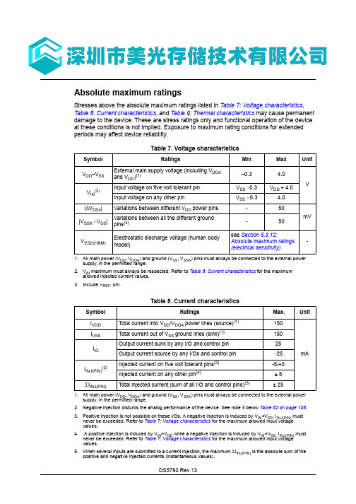
DS5792 Rev 13Absolute maximum ratingsStresses above the absolute maximum ratings listed in Table 7: Voltage characteristics , Table 8: Current characteristics , and Table 9: Thermal characteristics may cause permanent damage to the device. These are stress ratings only and functional operation of the device at these conditions is not implied. Exposure to maximum rating conditions for extended periods may affect device reliability.Table 7. Voltage characteristicsSymbol RatingsMin Max UnitV DD –V SS External main supply voltage (including V DDAand V DD)(1)1.All main power (V DD , V DDA ) and ground (V SS , V SSA ) pins must always be connected to the external powersupply, in the permitted range.–0.3 4.0V V IN (2)2.V IN maximum must always be respected. Refer to Table 8: Current characteristics for the maximumallowed injected current values.Input voltage on five volt tolerant pin V SS − 0.3V DD + 4.0 Input voltage on any other pinV SS − 0.34.0|ΔV DDx |Variations between different V DD power pins -50mV |V SSX − V SS |Variations between all the different ground pins (3)3.Include V REF- pin.-50V ESD(HBM)Electrostatic discharge voltage (human body model)see Section 5.3.12:Absolute maximum ratings (electrical sensitivity)-Table 8. Current characteristicsSymbol RatingsMax.UnitI VDD Total current into V DD /V DDA power lines (source)(1)1.All main power (V DD , V DDA ) and ground (V SS , V SSA ) pins must always be connected to the external powersupply, in the permitted range.150mA I VSS Total current out of V SS ground lines (sink)(1)150I IO Output current sunk by any I/O and control pin 25Output current source by any I/Os and control pin − 25I INJ(PIN)(2)2.Negative injection disturbs the analog performance of the device. See note 3 below Table 62 on page 108.Injected current on five volt tolerant pins (3)3.Positive injection is not possible on these I/Os. A negative injection is induced by V IN <V SS . I INJ(PIN) mustnever be exceeded. Refer to Table 7: Voltage characteristics for the maximum allowed input voltage values.-5/+0Injected current on any other pin (4)4.A positive injection is induced by V IN >V DD while a negative injection is induced by V IN <V SS . I INJ(PIN) must never be exceeded. Refer to Table 7: Voltage characteristics for the maximum allowed input voltage values.± 5ΣI INJ(PIN)Total injected current (sum of all I/O and control pins)(5)5.When several inputs are submitted to a current injection, the maximum ΣI INJ(PIN) is the absolute sum of thepositive and negative injected currents (instantaneous values).± 25Electrical characteristics STM32F103xC, STM32F103xD, STM32F103xEDS5792 Rev 135.3 Operating conditions5.3.1General operating conditionsTable 9. Thermal characteristicsSymbol RatingsValue Unit T STG Storage temperature range –65 to +150°C T JMaximum junction temperature150°CTable 10. General operating conditionsSymbol ParameterConditionsMin Max Unitf HCLK Internal AHB clock frequency -0 72MHz f PCLK1Internal APB1 clock frequency -0 36f PCLK2Internal APB2 clock frequency -0 72V DDStandard operating voltage -2 3.6V V DDA (1)1.When the ADC is used, refer to Table 59: ADC characteristics .Analog operating voltage(ADC not used)Must be the same potential as V DD (2)2.It is recommended to power V DD and V DDA from the same source. A maximum difference of 300mVbetween V DD and V DDA can be tolerated during power-up and operation.2 3.6VAnalog operating voltage (ADC used)2.43.6V BATBackup operating voltage- 1.8 3.6V P DPower dissipation at T A = 85°C for suffix 6 or T A = 105°C for suffix 7(3)3.If T A is lower, higher P D values are allowed as long as T J does not exceed T J max (see Table 6.7: Thermalcharacteristics on page 132).LQFP144-666mW LQFP100-434LQFP64-444LFBGA100-500LFBGA144-500WLCSP64-400T AAmbient temperature for 6 suffix versionMaximum power dissipation -4085°C Low-power dissipation (4)4.In low-power dissipation state, T A can be extended to this range as long as T J does not exceed T J max (seeTable 6.7: Thermal characteristics on page 132).-40105Ambient temperature for 7 suffix versionMaximum power dissipation -40105°CLow-power dissipation (4)-40125T JJunction temperature range6 suffix version -40105°C7 suffix version-40125DS5792 Rev 13STM32F103xC, STM32F103xD, STM32F103xE Electrical characteristics5.3.2 Operating conditions at power-up / power-downThe parameters given in Table 11 are derived from tests performed under the ambienttemperature condition summarized in Table 10.5.3.3 Embedded reset and power control block characteristicsThe parameters given in Table 12 are derived from tests performed under ambient temperature and V DD supply voltage conditions summarized in Table 10.Table 11. Operating conditions at power-up / power-downSymbol ParameterConditionsMin Max Unit t VDDV DD rise time rate -0∞µs/VV DD fall time rate20∞Table 12. Embedded reset and power control block characteristicsSymbolParameterConditionsMin Typ Max UnitV PVDProgrammable voltage detector level selection PLS[2:0]=000 (rising edge) 2.1 2.18 2.26V PLS[2:0]=000 (falling edge)2 2.08 2.16PLS[2:0]=001 (rising edge) 2.19 2.28 2.37PLS[2:0]=001 (falling edge) 2.09 2.18 2.27PLS[2:0]=010 (rising edge) 2.28 2.38 2.48PLS[2:0]=010 (falling edge) 2.18 2.28 2.38PLS[2:0]=011 (rising edge)2.38 2.48 2.58PLS[2:0]=011 (falling edge) 2.28 2.38 2.48PLS[2:0]=100 (rising edge)2.47 2.58 2.69PLS[2:0]=100 (falling edge) 2.37 2.48 2.59PLS[2:0]=101 (rising edge) 2.57 2.68 2.79PLS[2:0]=101 (falling edge) 2.47 2.58 2.69PLS[2:0]=110 (rising edge) 2.66 2.78 2.9PLS[2:0]=110 (falling edge) 2.56 2.68 2.8PLS[2:0]=111 (rising edge) 2.76 2.883PLS[2:0]=111 (falling edge)2.66 2.78 2.9V PVDhyst (2)PVD hysteresis--100-mV V POR/PDR Power on/power down reset threshold Falling edge 1.8(1)1.The product behavior is guaranteed by design down to the minimum V POR/PDR value.1.88 1.96V Rising edge 1.84 1.922.0V PDRhyst (2)PDR hysteresis--40-mV T RSTTEMPO (2)2.Guaranteed by design.Reset temporization-12.54.5msElectrical characteristics STM32F103xC, STM32F103xD, STM32F103xEDS5792 Rev 13DS5792 Rev 13STM32F103xC, STM32F103xD, STM32F103xE Electrical characteristicsTable 14. Maximum current consumption in Run mode, code with data processingrunning from FlashSymbolParameterConditionsf HCLK Max (1)1.Guaranteed by characterization results.UnitT A = 85°CT A = 105°CI DDSupply current in Run modeExternal clock (2), all peripherals enabled 2.External clock is 8 MHz and PLL is on when f HCLK > 8 MHz.72 MHz 6970mA48 MHz5050.536 MHz 3939.524 MHz272816 MHz2020.58 MHz 1111.5External clock (2), all peripherals disabled 72 MHz 3737.548 MHz2828.536 MHz 2222.524 MHz16.51716 MHz 12.5138 MHz88Table 15. Maximum current consumption in Run mode, code with data processingrunning from RAMSymbolParameterConditionsf HCLK Max (1)1.Guaranteed by characterization results at V DD max, f HCLK max.UnitT A = 85°CT A = 105°CI DDSupply current in Run modeExternal clock (2), all peripherals enabled 2.External clock is 8 MHz and PLL is on when f HCLK > 8 MHz.72 MHz 6667mA48 MHz43.545.536 MHz 333524 MHz2324.516 MHz16188 MHz 910.5External clock (2), all peripherals disabled 72 MHz 3333.548 MHz2323.536 MHz 1818.524 MHz1313.516 MHz 1010.58 MHz66.5。
STM32F103_数据手册(中文)
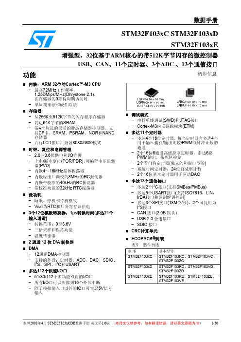
系统时钟的选择是在启动时进行,复位时内部8MHz的RC振荡器被选为默认的CPU时钟,随后可以选 择外部的、具失效监控的4~16MHz时钟;当外部时钟失效时,它将被隔离,同时产生相应的中断。 同样,在需要时可以采取对PLL时钟完全的中断管理(如当一个外接的振荡器失效时)。 具有多个预分频器用于配置AHB的频率、高速APB(APB2)和低速APB(APB1)区域。AHB和高速APB 的最高频率是72MHz,低速APB的最高频率为36MHz。参考图二的时钟驱动框图。
参照2008年4月 STM32F103xCDE数据手册 英文第1.0版 (本译文仅供参考,如有翻译错误,请以英文原稿为准)
4/30
STM32F103xC, STM32F103xD, STM32F103xE数据手册
● 代码可以在除PC卡外的片外存储器运行; ● 目标频率为SYSCLK/2,即当系统时钟为72MHz时,外部访问的速度可达36MHz;
STM32F103xC、STM32F103xD和STM32F103xE增强型系列拥有内置的ARM核心,因此它与
所有的ARM工具和软件兼容。
图一是该系列产品的功能框图。
内置闪存存储器
高达512K字节的内置闪存存储器,用于存放程序和数据。
CRC(循环冗余校验)计算单元
CRC(循环冗余校验)计算单元使用一个固定的多项式发生器,从一个32位的数据字产生一个CRC码。 在众多的应用中,基于CRC的技术被用于验证数据传输或存储的一致性。在EN/IEC 60335-1标准的范 围内,它提供了一种检测闪存存储器错误的手段,CRC计算单元可以用于实时地计算软件的签名, 并与在链接和生成该软件时产生的签名对比。
− 多达3个SPI接口(18M位/秒),2个可复用为 I2S接口
stm32f103中文资料
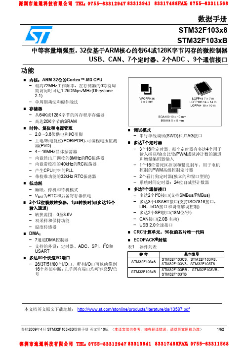
数据手册参照2009年4月 STM32F103x8B 数据手册 英文第10版 (本译文仅供参考,如有翻译错误,请以英文原稿为准) 1/62STM32F103x8 STM32F103xB中等容量增强型,32位基于ARM 核心的带64或128K 字节闪存的微控制器USB 、CAN 、7个定时器、2个ADC 、9个通信接口功能■ 内核:ARM 32位的Cortex™-M3 CPU− 最高72MHz 工作频率,在存储器的0等待周期访问时可达1.25DMips/MHz(Dhrystone 2.1)− 单周期乘法和硬件除法 ■ 存储器− 从64K 或128K 字节的闪存程序存储器 − 高达20K 字节的SRAM ■ 时钟、复位和电源管理− 2.0~3.6伏供电和I/O 引脚 − 上电/断电复位(POR/PDR)、可编程电压监测器(PVD)− 4~16MHz 晶体振荡器− 内嵌经出厂调校的8MHz 的RC 振荡器 − 内嵌带校准的40kHz 的RC 振荡器 − 产生CPU 时钟的PLL− 带校准功能的32kHz RTC 振荡器 ■ 低功耗− 睡眠、停机和待机模式− V BAT 为RTC 和后备寄存器供电■ 2个12位模数转换器,1μs 转换时间(多达16个输入通道)− 转换范围:0至3.6V − 双采样和保持功能 − 温度传感器 ■ DMA :− 7通道DMA 控制器− 支持的外设:定时器、ADC 、SPI 、I 2C 和USART ■ 多达80个快速I/O 端口− 26/37/51/80个I/O 口,所有I/O 口可以映像到16个外部中断;几乎所有端口均可容忍5V 信号■ 调试模式− 串行单线调试(SWD)和JTAG 接口■ 多达7个定时器− 3个16位定时器,每个定时器有多达4个用于输入捕获/输出比较/PWM 或脉冲计数的通道和增量编码器输入− 1个16位带死区控制和紧急刹车,用于电机控制的PWM 高级控制定时器− 2个看门狗定时器(独立的和窗口型的) − 系统时间定时器:24位自减型计数器 ■ 多达9个通信接口− 多达2个I 2C 接口(支持SMBus/PMBus) − 多达3个USART 接口(支持ISO7816接口,LIN ,IrDA 接口和调制解调控制) − 多达2个SPI 接口(18M 位/秒) − CAN 接口(2.0B 主动) − USB 2.0全速接口 ■ CRC 计算单元,96位的芯片唯一代码 ■ ECOPACK ®封装 表1 器件列表参 考 基本型号STM32F103x8STM32F103C8、STM32F103R8、STM32F103V8、STM32F103T8 STM32F103xBSTM32F103RB 、STM32F103VB 、STM32F103TB本文档英文原文下载地址: /stonline/products/literature/ds/13587.pdf目录1介绍 (4)2规格说明 (5)2.1器件一览 (5)2.2系列之间的全兼容性 (6)2.3概述 (6)2.3.1ARM®的Cortex™-M3核心并内嵌闪存和SRAM (6)2.3.2内置闪存存储器 (6)2.3.3CRC(循环冗余校验)计算单元 (6)2.3.4内置SRAM (7)2.3.5嵌套的向量式中断控制器(NVIC) (7)2.3.6外部中断/事件控制器(EXTI) (7)2.3.7时钟和启动 (7)2.3.8自举模式 (7)2.3.9供电方案 (7)2.3.10供电监控器 (8)2.3.11电压调压器 (8)2.3.12低功耗模式 (8)2.3.13DMA (8)2.3.14RTC(实时时钟)和后备寄存器 (8)2.3.15定时器和看门狗 (9)2.3.16I2C总线 (10)2.3.17通用同步/异步收发器(USART) (10)2.3.18串行外设接口(SPI) (10)2.3.19控制器区域网络(CAN) (10)2.3.20通用串行总线(USB) (10)2.3.21通用输入输出接口(GPIO) (10)2.3.22ADC(模拟/数字转换器) (10)2.3.23温度传感器 (11)2.3.24串行单线JTAG调试口(SWJ-DP) (11)3引脚定义 (13)4存储器映像 (21)5电气特性 (22)5.1测试条件 (22)5.1.1最小和最大数值 (22)5.1.2典型数值 (22)5.1.3典型曲线 (22)5.1.4负载电容 (22)5.1.5引脚输入电压 (22)5.1.6供电方案 (23)5.1.7电流消耗测量 (23)参照2009年4月 STM32F103x8B数据手册英文第10版(本译文仅供参考,如有翻译错误,请以英文原稿为准) 2/625.2绝对最大额定值 (23)5.3工作条件 (25)5.3.1通用工作条件 (25)5.3.2上电和掉电时的工作条件 (25)5.3.3内嵌复位和电源控制模块特性 (25)5.3.4内置的参照电压 (26)5.3.5供电电流特性 (26)5.3.6外部时钟源特性 (33)5.3.7内部时钟源特性 (37)5.3.8PLL特性 (38)5.3.9存储器特性 (38)5.3.10EMC特性 (38)5.3.11绝对最大值(电气敏感性) (39)5.3.12I/O端口特性 (40)5.3.13NRST引脚特性 (42)5.3.14TIM定时器特性 (43)5.3.15通信接口 (43)5.3.16CAN(控制器局域网络)接口 (47)5.3.1712位ADC特性 (47)5.3.18温度传感器特性 (51)6封装特性 (52)6.1封装机械数据 (52)6.2热特性 (59)6.2.1参考文档 (59)6.2.2选择产品的温度范围 (59)7订货代码 (61)8版本历史 (62)参照2009年4月 STM32F103x8B数据手册英文第10版(本译文仅供参考,如有翻译错误,请以英文原稿为准) 3/621 介绍本文给出了STM32F103x8和STM32F103xB中等容量增强型产品的订购信息和器件的机械特性。
stm32f103中文手册[12]
![stm32f103中文手册[12]](https://img.taocdn.com/s3/m/e697aebd8662caaedd3383c4bb4cf7ec4afeb60a.png)
stm32f103中文手册1. 概述72 MHz的主频,可达90 DMIPS的性能64 KB至512 KB的闪存,20 KB至64 KB的SRAM7个定时器,包括3个高级定时器和4个通用定时器2个12位模数转换器,每秒1 MSPS2个I2C接口,3个USART接口,2个SPI接口1个USB 2.0全速接口1个CAN 2.0B接口37至80个GPIO引脚,支持中断和唤醒功能3个12位数字摹拟转换器实时时钟,支持日历和闹钟功能4至16 MHz的晶振振荡器,内部8 MHz的RC振荡器,内部40 kHz的RC振荡器7种低功耗模式,包括待机模式、住手模式和睡眠模式单电源3.0 V至3.6 V或者双电源1.8 V至3.6 V工作电压工作温度范围为-40°C至+85°C或者-40°C至+105°C2. 引脚定义stm32f103有多种封装形式,包括LQFP64、LQFP100、LQFP144、BG A100等²。
不同封装形式的引脚数量和罗列方式不同,但引脚功能基本相同。
下表列出了stm32f103的引脚功能和描述:---引脚名称 ---引脚功能 ---引脚描述 -------:------: ---:------: ---:------: -------VSS ---接地 ---连接到电源地 -------VDD ---电源 ---连接到正电源 -------VDDA ---摹拟电源 ---连接到正电源 -------VSSA ---摹拟接地 ---连接到电源地 -------NRST ---复位 ---复位输入,低电平有效 -------BOOT0 ---引导模式选择 ---引导模式选择输入,高电平或者低电平 -------BOOT1 ---引导模式选择 ---引导模式选择输入,高电平或者低电平 -------OSC_IN ---晶振输入 ---连接到外部晶振或者时钟信号的输入端-------OSC_OUT ---晶振输出 ---连接到外部晶振或者时钟信号的输出端 -------PA0~PA15 ---端口A引脚 ---可编程I/O引脚,具有多种功能和特性 -------PB0~PB15 ---端口B引脚 ---可编程I/O引脚,具有多种功能和特性 -------PC0~PC15 ---端口C引脚 ---可编程I/O引脚,具有多种功能和特性 -------PD0~PD15 ---端口D引脚 ---可编程I/O引脚,具有多种功能和特性 -------PE0~PE15 ---端口E引脚 ---可编程I/O引脚,具有多种功能和特性 -------JTAG_TMS ---JTAG测试模式选择 ---JTAG接口的测试模式选择信号 -------JTAG_TCK ---JTAG测试时钟 ---JTAG接口的测试时钟信号 -------JTAG_TDI ---JTAG测试数据输入 ---JTAG接口的测试数据输入信号 -------JTAG_TDO ---JTAG测试数据输出 ---JTAG接口的测试数据输出信号 -------JTAG_TRST ---JTAG测试复位 ---JTAG接口的测试复位信号 ----3. 系统架构stm32f103的系统架构如下图所示³:32位RISC架构,支持Thumb-2指令集3级流水线,支持分支预测和异常处理13个通用寄存器和1个程序计数器1个嵌套向量中断控制器(NVIC),支持多达60个中断源1个系统控制块(SCB),包含系统配置、控制和状态寄存器1个系统定时器(SysTick),提供一个24位递减计数器,可用于操作系统的节拍计时1个调试接入端口(DAP),支持JTAG和SWD两种调试协议闪存:是stm32f103的非易失性存储器,用于存储程序代码和数据。
stm32f103rct6中文资料_数据手册_参数

家庭:嵌入式-微控制器 系列:STM32 芯体尺寸:32-位 速度:72MHz 连通性:CAN,I2C,IrDA,LIN,SPI,UART/USART,USB 外围设备:DMA,电机控制PWM,PDR,POR,PVD,PWM,温度传感器,WDT 输入/输出数:51 程序存储器容量:256KB (256K x 8) RAM容量:48K x 8 电压-电源(Vcc/Vdd):2 V ~ 3.6 V 振荡器型:内部 工作温度:-40°C ~ 85°C 封装/外壳:64-LQFP 包装:托盘 STM32F103RCT6是一种嵌入式-微控制器的集成电路(IC),是由ST公司开发的STM32F103RCT6系列的其中一种,芯体尺寸是32位,速度是72MHz,程序存储器容 量是256KB,程序存储器类型是FLASH,RAM容量是48K。 STM32F103F103通过I/O 接口与TFT液晶模块相连接,虽然很多的TFT液晶模块中内置的液晶屏控制器都支持SPI 接口通信(如ILI9325)但由于SPI传输速度较慢不利 于液晶数据的快速传输,因此很多液晶模块都选择采用并口通信。 其中PB0-PB15分别与D0-D15相连作为数据通信口,PA0、PA4、PA5、PA6、PA7 分别连接RESET、CS、RS、WR、RD,作为控制口,实现复位、片选、指令数 据切换、读写等控制功能。 软件部分的编程采用C语言,一方面主要完成STM32F103对I/O 管脚的配置,用来实现对四线电阻触摸屏端子状态的控制,通过中断方 式检测是否有触摸信息,配置A/D转换通道,读入电压根据公式计算出触点坐标。另一方面主要完成通过与TFT液晶模块的通信控制,实现触摸点坐标与液晶屏坐 标的对应并有效完成显示任务。软件的开发环境是MDK,MDK 将ARM 开发工具RealView DevelopmentSuite(简称为RVDS)的编译器RVCT与Keil的工程管理、调试 仿真工具集成在一起,支持ARM7、ARM9和最新的Cortex-M3核处理器,自动配置启动代码,集成Flash烧写模块,强大的Simulation设备模拟,性能分析等功能,与 ARM 之前的工具包ADS等相比,RealView编译器的最新版本可将性能改善超过20%.本文提出了基于STM32F103RCT6单片机的EMS液晶显示触摸屏的设计方 案。STM32F103F103的高速、低耗的优越性能完全可以达到触摸屏的主控制芯片要求,TFT液晶显示器可以满足更复杂、多彩、灵活的显示任务,符合显示屏性能 不断攀升的发展趋势。本设计充分利用了STM32F103芯片的优势,抛弃了传统触摸屏控制器控制触摸屏的方案,利用自身A/D完成了触摸屏功能,本方案大大简化 了硬件电路结构,通信更可靠,编程也更加简洁,最终既能达到EMS显示要求,出色地显示和设置了系统所需要的数据,又能降低系统的成本,通过实际使用达到 了良好的效果。鉴于当前电动车的快速发展,本方案可以拥有不错的应用前景。
- 1、下载文档前请自行甄别文档内容的完整性,平台不提供额外的编辑、内容补充、找答案等附加服务。
- 2、"仅部分预览"的文档,不可在线预览部分如存在完整性等问题,可反馈申请退款(可完整预览的文档不适用该条件!)。
- 3、如文档侵犯您的权益,请联系客服反馈,我们会尽快为您处理(人工客服工作时间:9:00-18:30)。
Features•Core: Arm® 32-bit Cortex®-M3 CPU–72 MHz maximum frequency, 1.25DMIPS/MHz (Dhrystone 2.1) performance at 0 wait statememory access–Single-cycle multiplication and hardwaredivision•Memories–256 to 512 Kbytes of Flash memory–up to 64 Kbytes of SRAM–Flexible static memory controller with 4 Chip Select. Supports Compact Flash, SRAM,PSRAM, NOR and NAND memories–LCD parallel interface, 8080/6800 modes •Clock, reset and supply management – 2.0 to 3.6V application supply and I/Os–POR, PDR, and programmable voltage detector (PVD)–4-to-16 MHz crystal oscillator–Internal 8 MHz factory-trimmed RC–Internal 40 kHz RC with calibration–32 kHz oscillator for RTC with calibration •Low power–Sleep, Stop and Standby modes–V BAT supply for RTC and backup registers • 3 × 12-bit, 1 µs A/D converters (up to 21channels)–Conversion range: 0 to 3.6 V–Triple-sample and hold capability–Temperature sensor• 2 × 12-bit D/A converters•DMA: 12-channel DMA controller–Supported peripherals: timers, ADCs, DAC, SDIO, I2Ss, SPIs, I2Cs and USARTs •Debug mode–Serial wire debug (SWD) & JTAG interfaces–Cortex®-M3 Embedded Trace Macrocell™•Up to 112 fast I/O ports–51/80/112 I/Os, all mappable on 16 external interrupt vectors and almost all 5V-tolerant •Up to 11 timers–Up to four 16-bit timers, each with up to 4IC/OC/PWM or pulse counter and quadrature(incremental) encoder input– 2 × 16-bit motor control PWM timers with dead-time generation and emergency stop– 2 × watchdog timers (Independent and Window)–SysTick timer: a 24-bit downcounter– 2 × 16-bit basic timers to drive the DAC•Up to 13 communication interfaces–Up to 2 × I2C interfaces (SMBus/PMBus)–Up to 5 USARTs (ISO 7816 interface, LIN, IrDA capability, modem control)–Up to 3 SPIs (18 Mbit/s), 2 with I2S interface multiplexed–CAN interface (2.0B Active)–USB 2.0 full speed interface–SDIO interface•CRC calculation unit, 96-bit unique ID •ECOPACK® packagesTable 1.Device summary Reference Part numberSTM32F103xCSTM32F103RC STM32F103VCSTM32F103ZCSTM32F103xDSTM32F103RD STM32F103VDSTM32F103ZDSTM32F103xESTM32F103RE STM32F103ZESTM32F103VE找Memory、FPGA、二三极管、连接器、模块、光耦、电容电阻、单片机、处理器、晶振、传感器、滤波器,上深圳市美光存储技术有限公司July 2018DS5792 Rev 13STM32F103xC, STM32F103xD, STM32F103xE Electrical characteristicsElectrical characteristics STM32F103xC, STM32F103xD, STM32F103xEDS5792 Rev 135.3 Operating conditions5.3.1General operating conditionsTable 9. Thermal characteristicsSymbol RatingsValue Unit T STG Storage temperature range –65 to +150°C T JMaximum junction temperature150°CTable 10. General operating conditionsSymbol ParameterConditionsMin Max Unitf HCLK Internal AHB clock frequency -0 72MHz f PCLK1Internal APB1 clock frequency -0 36f PCLK2Internal APB2 clock frequency -0 72V DDStandard operating voltage -2 3.6V V DDA (1)1.When the ADC is used, refer to Table 59: ADC characteristics .Analog operating voltage(ADC not used)Must be the same potential as V DD (2)2.It is recommended to power V DD and V DDA from the same source. A maximum difference of 300mVbetween V DD and V DDA can be tolerated during power-up and operation.2 3.6VAnalog operating voltage (ADC used)2.43.6V BATBackup operating voltage- 1.8 3.6V P DPower dissipation at T A = 85°C for suffix 6 or T A = 105°C for suffix 7(3)3.If T A is lower, higher P D values are allowed as long as T J does not exceed T J max (see Table 6.7: Thermalcharacteristics on page 132).LQFP144-666mW LQFP100-434LQFP64-444LFBGA100-500LFBGA144-500WLCSP64-400T AAmbient temperature for 6 suffix versionMaximum power dissipation -4085°C Low-power dissipation (4)4.In low-power dissipation state, T A can be extended to this range as long as T J does not exceed T J max (seeTable 6.7: Thermal characteristics on page 132).-40105Ambient temperature for 7 suffix versionMaximum power dissipation -40105°CLow-power dissipation (4)-40125T JJunction temperature range6 suffix version -40105°C7 suffix version-40125STM32F103xC, STM32F103xD, STM32F103xE Electrical characteristics5.3.2 Operating conditions at power-up / power-downThe parameters given in Table 11 are derived from tests performed under the ambienttemperature condition summarized in Table 10.Table 11. Operating conditions at power-up / power-downSymbol ParameterConditionsMin Max Unit t VDDV DD rise time rate -0∞µs/VV DD fall time rate20∞Electrical characteristics STM32F103xC, STM32F103xD, STM32F103xE5.3.4 Embedded reference voltageThe parameters given in Table 13 are derived from tests performed under ambienttemperature and V DD supply voltage conditions summarized in Table 10.Table 13. Embedded internal reference voltageSymbol ParameterConditions Min Typ Max Unit V REFINTInternal reference voltage –40 °C < T A < +105 °C 1.16 1.20 1.26V–40 °C < T A < +85 °C1.16 1.20 1.24T S_vrefint(1)1.Shortest sampling time can be determined in the application by multiple iterations.ADC sampling time when reading the internal reference voltage-- 5.117.1(2)2.Guaranteed by design.µsV RERINT(2)Internal reference voltage spread over the temperature rangeV DD = 3 V ±10 mV--10mV T Coeff (2)Temperature coefficient---100ppm/°C。
