ABB吊舱式推进器水下安装介绍
自卸船吊舱推进器基座环内场加工方式探索
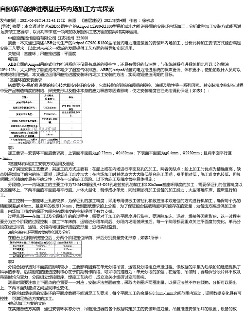
自卸船吊舱推进器基座环内场加工方式探索发布时间:2021-06-08T14:32:43.127Z 来源:《基层建设》2021年第4期作者:徐佛忠[导读] 摘要:本文通过简述ABB公司生产的Azipod CZ980-R1800型吊舱式电力推进装置的安装环内场加工,分析此种加工安装方式能否满足安装工艺要求,以此对未来这一领域的发展提供工艺方面的指导和实际运用。
中船澄西扬州船舶有限公司江苏扬州 225000摘要:本文通过简述ABB公司生产的Azipod CZ980-R1800型吊舱式电力推进装置的安装环内场加工,分析此种加工安装方式能否满足安装工艺要求,以此对未来这一领域的发展提供工艺方面的指导和实际运用。
关键词:基座环;吊舱推进器;平面度0前言ABB公司的Azipod吊舱式电力推进系统不仅具有卓越的操控性,还具有很好的节油性,与传统轴系推进系统相比可以节约燃油10%-15%,大大降低了燃油成本并减少了温室气体排放。
ABB的Azipod吊舱式电力推进系统的噪声更低、体积更小,使船舶设计人员可以有效地利用空间。
本文通过运用吊舱推进器安装环内场加工安装的方法,实现缩短建造周期的目标。
1基座环的安装要求搭载要求--吊舱推进器的核心技术即安装环的安装,它直接影响到船舶后期的操控、油耗及稳性等一系列因素。
其安装精度控制在过程中受产品制造精度的制约、焊接变形以及船体本身的应力释放等因素影响,使之安装精度往往无法得到保证(如表1):表1加工要求—安装环平面度要求高,上表面平面度为≤0.75mm,Φ2450mm;下表面平面度为≤0.4mm,Φ2950mm;且两平面平行度≤1mm。
2基座环内场加工安装方式运用及验证为了满足安装工艺要求,其加工的方式主要有:在船上或在内场进行平面及孔的加工。
两者优缺点:船上加工时优点为精确度高,缺点则是增加了船台的施工周期,现场施工难度加大;在内场加工时其优点为大大降低船台施工周期,费用相对低,施工难度也较低。
全回转吊舱式推进器线型设计

全回转吊舱式推进器线型设计朱东华;魏菲菲【摘要】对吊舱推进器的特点、水动力性能以及代表厂商和产品进行了介绍.通过对线型设计时所需注意事项的分析,展示了其在多种船型领域的适用性.【期刊名称】《船舶设计通讯》【年(卷),期】2014(000)002【总页数】4页(P10-13)【关键词】吊舱推进器;线型设计;水动力性能【作者】朱东华;魏菲菲【作者单位】上海船舶研究设计院,上海201203;上海船舶研究设计院,上海201203【正文语种】中文【中图分类】U664.30 前言全回转吊舱式推进器(又称POD推进器,简称吊舱式推进器)是由动力驱动固定在水下船体之外吊舱之内的螺旋桨,吊舱可以绕其纵轴360°旋转,自由地向任何方向推进。
吊舱式推进器的概念是在20世纪80年代末提出的,是一种全新的推进理念。
它集推进和操舵装置于一体,极大地增加了船舶设计、建造和使用的灵活性。
吊舱式推进器广泛应用在客船(邮轮或渡轮)、大型集装箱船、钻井平台、海洋工程支援船、客滚船、游艇、科学考察船、打捞船和 LNG 船上[1]。
1 吊舱式推进器特点[2-3]1.1 优点吊舱式推进器和传统推进器比较有许多优点:1)节能减排。
选用吊舱式推进器可以调节电机(或液压马达)的转速来适应外部变化的载荷,发动机将处在最佳状态运转,提高了能效水平,延长了发动机的寿命,实现节能减排的目的。
2)操纵性能好。
推进器可在360°范围内旋转,极大地提高了船舶的操纵性和机动性。
3)噪声更低、振动更小。
与常规桨相比,吊舱式推进器的桨盘面处可得到更均匀的来流,从而明显减少振动、降低噪声。
4)结构简单可靠。
5)提高舱容利用率。
采用吊舱式推进器可以重新优化尾部线型,充分利用机舱舱容,使船体设计尤其是船尾和集控室部分的设计具有很大的灵活性。
6)安装维护方便。
采用模块化设计、安装,缩短了船舶建造和维修周期。
1.2 缺点1)一次性投资成本增加。
2)由于船舶安装了多种新型设备,因此需要高素质的高级船员。
推进器安装方法与流程

推进器安装方法与流程Installing a Propeller: Methods and ProceduresInstalling a propeller is a crucial step in ensuring the smooth and efficient operation of a watercraft, whether it's a boat, jet ski, or even a larger vessel like a cruise ship. The process involves several key steps that must be followed carefully to avoid any damage to the propeller or the watercraft itself.The first step is to prepare the area where the propeller will be installed. This involves clearing any debris or obstacles that could interfere with the installation process. It's also important to ensure that the area is dry and free of any moisture, as water can damage the propeller's components.Once the area is prepared, the next step is to remove the old propeller, if there is one. This usually requires the use of special tools, such as a wrench or a socket set, to loosen and remove the bolts that secure the propeller to the shaft. Once the old propeller is removed, it's important to inspect the shaft for any damage or corrosion.If the shaft is in good condition, the next step is to install the new propeller. This involves lining up the holes in the propeller with the shaft and then securing it in place with bolts. It's crucial to ensure that the propeller is properly aligned with the shaft toavoid any issues with balance or vibration.Once the propeller is securely installed, the final step is to test it. This involves starting the engine and observing the propeller's operation. It's important to check for any vibrations or noises that could indicate a problem with the installation. If everything appears to be working properly, the installation is complete.推进器的安装方法与流程安装推进器是确保水上工具如船只、喷气式滑水板甚至大型游船如游轮平稳、高效运行的关键步骤。
详述全回转吊舱电力推进器的安装工艺及实施

详述全回转吊舱电力推进器的安装工艺及实施摘要:本文介绍某自卸船两台全回转吊舱电力推进器(以下简称电推)的安装及精度控制过程,通过电推法兰片体组立(以下简称组立)制作精度控制、拉线定位、平面度控制等措施,实现实船精准安装,解决电推法兰纵倾角与双轴线定位的安装难题。
实践证明,该安装工艺对该类型推进器的安装具有重要的指导作用和参考价值。
关键词:电推组立拉线定位平面度控制精准安装0引言船舶航行过程中采用电推作为动力已成为主流,其突出特点是操纵性能好,螺旋桨可绕垂直轴作360°回转,其结构简单,体积小,更经济节能,运行可靠且灵活,能使船舶原地回转、紧急停止、急速转弯、快速进退和瞬时适应海况变化,消除负载瞬态。
某自卸船艉部配置两台全回转电推,舵线纵倾角7±0.1°。
实船电推安装、轴舵线定位精度要求高、工艺复杂,是该船建造的一大难题,所以对电推的安装必须深入策划与研究,并编制了相应的安装工艺指导生产施工,下面就对该设备的安装工艺以及现场具体实施进行细述。
1 组立的制作与精度控制为缩短船台建造周期,提高建造精度,技术先行,策划研究了组立的制作和精度控制的技术方案,以实现船台阶段本组立的精准定位和快速合拢搭接,提供坚实基础。
1.1组立的制作精度控制由于组立的结构型式相对较弱,在制作时要考虑其焊接变形和后期机加工装夹时引起的变形须对其临时加强。
工艺方案决定在放射状T型肘板间增加20#槽钢加强,加强离法兰100mm处布置,槽钢两端满焊,中间双面点焊,焊点长度大于50mm,双面不小于4个焊点,槽钢上船台后割除。
1.2组立法兰及螺纹孔内场加工该电推法兰上布置了75个M42的螺纹孔和3个φ53Xφ100的安装导向孔,法兰厚度100±2mm,法兰上平面平面度要求0.75mm以内,下平面平面度0.4mm以内,加工精度极高。
若在船台上直接外镗加工法兰平面与钻孔攻丝,船台周期长,费工费时,施工困难,环境恶劣。
11830吊舱式电力推进装置的应用
上海造船 2007年第 1期 (总第 69期 )
— 19 —
(ACS600W ) 、1套 5次谐波滤波器和 1 套紧凑型吊 舱式推进装置 (Azipod)组成 。 3. 1 中心电站
中心电站设有 3台主柴油发电机组 (每台机组 功率为 1 800 kW , 1 000 r/m in, 690 V , 50 Hz) , 1 台 停泊柴油发电机组 (机组功率为 600 kW , 1 000 r/ m in, 690 V , 50 Hz) 。主柴油发电机组既供推进电机 等动力系统的用电 ,又供船舶日常用电 。 3. 2 6脉冲推进变频器
1 前 言
由 708研究所设计 ,江南造船 (集团 )有限责任公
司建造的综合海洋监测船“中国海监 83”号是首艘由
我国自行设计的采用紧凑型吊舱装置的全电力推进
系统船舶 ,也是目前国内最大、设备最先进的综合海
洋监测船。其主要技术参数 :
总 长
98 m
垂线间长
86 m
型 宽
15. 2 m
型 深
(2) 690 V 电缆与 400 V 电缆分束 ; (3)每根电缆接地必须良好 。 经上述有效的技术措施 ,效果明显 。试航测试 报告显示 :发电机组 ( 1 800 kW ×3 + 600 kW )同时 工作 ,电站总负荷 4 140 kW , 690 V 电网的谐波值为 8. 6% (符合允许数值 10%以下 ) , 400 V 电网的谐 波值为 4. 3% (符合规范规定数值 5%以下 ) 。试航 中通信电子设备的工作正常 。
abb azipod吊舱推进器介绍
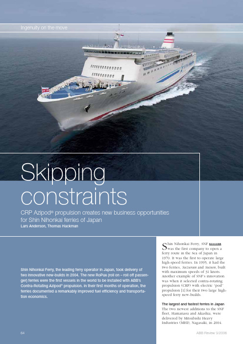
Ingenuity on the move SkippingIngenuity on the moveSkipping constraintsCRP Azipod propulsion, an azimuth-ing 17.6 MW Azipod unit installed in a contra-rotating mode, aft of the main propeller 1.There is always a risk involved when building a prototype. But, as CRP pod propulsion was the only solution able to achieve a 24-hour schedule and a daily ferry service, the decision to go ahead with the CRP Azipod propul-sion was taken. In doing so, SNF and MHI broke the decades-long deadlockin the marine industry’s attempt to seize the full benefits of contra-rotat-ing propulsion .Deliveries from ABB Marine included a 17.6 MW Azipod unit for each of the two ferries, working in tandem with a reduction-gear-driven CP (con-trollable pitch) pod propeller. ABBa lso delivered the control systems and the 27-MW, 6.6-kV power generationand distribution systems.The layout of the propulsionplant features two Wärtsilä 12V46 engines driving a CP propeller through a twin-in/single-out gearbox. Another pair of 12V46 engines drives alternators that feed electricalpower to the Azipod unit. The power distribution is 25.2 MW on the CP propeller and 17.6 MW on the Azipod, making 42.8 MW in total. In order to achieve the same vessel speed, a conventional twin-shaft propulsion system would require a total installedpower of approximately47 MW.Demanding weather conditionsThe weather conditions in the Sea of Japan can be divided into two distinct seasons, win-ter and summer. The winter season lasts from November through March and, during this time, the Sea of Japan is infamously stormy. The air temperature can drop below zero and, even though the sea never actually freezes, ice build-up on ships can be a problem. The winds during the winter storms often reach speeds of more than 30 m/s, with waves in excess of eight meters high.Shin Nihonkai normally de-lays or cancels ferry depar-tures when the height of the waves exceeds 5 meters but, because of the length of its routes, weather conditions vary and ferries can be de-layed by unexpected storms. Maintaining a high averageWith an overall length 224.5 meters, and with a service speed of 30.5 knots, these two RoPax ferries are the largest and fastest in Japan . They are also the first vessels in the world to take advantage of ABB’s contra-rotat-ing Azipod ® propulsion system.Major benefits from CRP pod propulsionShin Nihonkai Ferry operates an extensive network of ferry routes between the islands of Honshu and Hokkaido in northern Japan. The main reason for choos-ing CRP Azipod ® propulsion was the increasing cost ofbunker fuel. But a numberof additional benefits werealso gained.At 573 nautical miles, the Maizuru-Otaru route is the longest in the network. Be-cause of its length, the route had always required three ferries to provide a daily ser-vice. These three ferries, op-erating at 20 knots, covered the distance in 30 hours and were able to keep consistentarrival and departure times in both ports. In order to provide a daily service with only two ferries, the vessels needed to be larger and able to maintain a cruising speed of 30.5 knots. Shin Nihonkai Ferry had been investigating how this might be achieved, but real-ized that the cost, in terms of fuel consumption, at these speeds would havebeen prohibitive.For a two-ship solution tobe viable, a remarkable (yetrealistic) reduction in fuelconsumption would have tobe demonstrated to SNF.When presented with theCRP Azipod propulsion con-cept, which promised highfuel oil cost savings, ShinNihonkai Ferry becamei nterested. After intensiver esearch, MHI chose a sin-gle-skeg hull solution withShin Nihonkai Ferry Co., Ltd.Factbox 2 Ferry specificationsIngenuity on the moveSkipping constraintsour operations, we are also opening up new market opportunities.”Fuel consumption reduced by 20 percentThe target for Hamanasu and Akashia was to make a 10 percent saving in fuel oil consumption, as compared to conventional twin-screw ferries. In May 2004, Hamanasu was the first ship to embark on the much-anticipat-ed initial sea trials. In the speed tests, with a power split of 55 percent for the forward propeller and 45 percent of the aft, the vessel logged a maxi-mum speed of 32.04 knots – a remark-able achievement.Even more remarkable was the fuel oil consumption, which set a new benchmark in the industry. The seaspeed is essential: a reduction in speed of as little as 1.5 knots can cause an hour’s delay on this route.During the summer season, the weath-er is calmer but the ferry routes are prone to relatively frequent typhoons. These are fairly easy to predict as they tend to be slow moving. Nonetheless, a ferry can be forced to sail through a typhoon to maintain the daily service.Built to expectationsMr. Yasuo Iritani, President of ShinN ihonkai Ferry, explains that hed ecided to go ahead with the project based on the positive result of their studies of the concept.“The ships are somewhat more expen-sive than conventional ferries but the operational savings are big enough forus to recover the initial expense,” he explains. Mr Iritani also comments that, with the new ferries, SNF has achieved its main objective of operat-ing a 24-hour service on the Maizuru-Otaru route.Compared with the exist-ing service, the vehicle turnaround time isr educed by 25 percen.“Compared with the existing service, the vehicle turnaround time is re-duced by 25 percent, which is attrac-tive to cargo distributors. For exam-ple, the reduced transportation time makes us an alternative to air cargo for high-grade perishable foodstuffs. This means we are not only improvingW 12V46C12600 kWCRP AZIPOD 17,6 MWW 12V46C12600 kWW 12V46C12600 kWW 12V46C12600 kW2910 kWIngenuity on the moveSkipping constraintstrials confirmed the findings from the extensive test made in MHI’s model basin in Nagasaki. After severalmonths of operation on their intended route, the owner has learned that the new vessels, for the same 24-hour ser-vice, will save some 20 percent in fuel consumption compared to the two old twin-shaft, diesel-driven ferries, which operated temporarily on the route. The service speed of the twin-shaft ferries was only 29.4 knots and their transportation capacity was 15 percent less than that of the new ships.Improved maneuverability with Azipod ® propulsionThe maneuverability of the ship was also of great interest. When maneu-vering at low speeds and in port, the Azipod unit can be used as a rudder and side thruster. At cruising speeds the steering range of the Azipod isr estricted, but, despite their size,H amanasu and Akashia are able to maneuver at low speed, without tug assistance, in winds up to 18 m/s. Un-der these conditions, smaller, conven-tional, twin-screw ferries require assis-tance.Flexible operationThe propulsion plant also offers great flexibility in terms of power distribu-tion. For example, the ships carry a lot of perishable foodstuffs from Hok-kaido, including dairy produce and vegetables. The cargo is transported in refrigerated trailers that require electrical power. However, on their return trip to Hokkaido, refrigerationis not required and the electrical pow-er can be used, if necessary, for pro-pulsion. Conversely, if weather condi-tions are favorable, the ship can sail one trip with only three engines, and still remain on schedule.The new vessels, will save some 20 percent in fuel consumption compared to the two old twin-shaft, ferries.Operational experienceMr Kiyoshi Takaoka, Marine Depart-ment Manager, says that the companyis very pleased with the performance of the new ships. The maneuverability is excellent and the ships are very sta-ble in rough seas.Mr Takahashi, Hamanasu’s captain, is also more than satisfied with his ship:“Under normal weather conditions the course stability is excellent. We do not normally go out if the wave height is above five meters, but some-times typhoons are unavoidable. Last summer we experienced typhoons and wave heights above eight meters with extreme winds. We reduced speed to 20 knots and, although it was a rough ride, the ship was fully maneuvrable. When maneuvering inport, I feel very safe because of the1Contra-rotating propellershigh thrust available from the Azipod unit; equaling that of two tug boats.”“When slow-steaming at five knots and below, the steering performance with the Azipod is still remarkable. The acceleration when leaving port is much better compared [to that of] oth-er ships and, at full speed, the stern wave is very small, which indicates good fuel economy.”Having built these first two vessels, MHI can recommend Azipod CRP pro-pulsion both for ferries and for high-day-rate vessels such as LNG (liquid natural gas) carriers, where redundan-cy is important.Lars AndersonWärtsilä Switzerland, Ltd.Winterthur, Switzerland lars.anderson@ Thomas Hackman ABB Oy Helsinki, Finlandthomas.hackman@Reference[1] ABB Review, 3/2005. “Green shipping”, by MattiTurtiainen。
abb azipod吊舱推进器介绍

的价格是相同的) 与其人均能源消耗 要实现这种变化,这只是一个必要条 带来的好处;
之间的关系情况,经过多年的观测表 件,而不是一个充分条件1)。
■ 通过 ABB 公司赠送的柴油发电机,
明,经济的发展过程是从左边的较低
使更多的住户可以接上微型电网,
处逐步增加到右边的较高处。
成功的项目
另外还有一台新的水泵,使他们可
Thema
Themenb编er者eic按h
为了让世界更加美好……
电力和生产率创造美好世界,这是 ABB 公司的核心 和基础。 ABB 公司是世界上电力基础设施产品和系统 (其中 包括从家庭电气设施一直到发电设备)以及工厂自动化和 制造工业工艺流程最佳化产品和系统的主要供应商。电 力和自动化是现代经济的两个基石,它们的发展与能否 具备高效而可靠的供电能力有着密切的关系,也与能否 把生产力持续提升到世界先进水平有着很大关系。 一个可靠的、低成本的供电基础设施能够使工业界 将其主要精力集中到他们的核心业务上去,并为社会创 造价值;同样,具有高生产率的制造工艺流程也是如 此。ABB 公司致力于帮助社会上各行各业实现更加美 好未来。当然,这样做不仅有利于工业界也同样有利于 ABB公司自身。 在 ABB 公司内部也在为了创造更加美好的世界而不 断工作。为了实现可持续发展,公司开展了多种项目, 还贯彻实行了有关职工安全方面的很多方案。我们的可 持续发展年度报告对我们在这方面所做的工作都有一个 很好的全面介绍。 ABB 公司采用了许多途径和方法来改善人们的生活 质量,例如,一套安全的家庭电气设施,可靠的供水, 一次舒适的火车旅行,运行稳定的电梯,在足球场看台 上的一个向阳座椅等等,还有其它无数的相类似的产 品,所有一切都是为了让世界变得更加美好。但是,当 发达国家中的人们由于火车误点而感到不高兴时,在其 它地方还有十多亿的人还没有完全享受到电力所带来的 方便与舒适呢!所以,对于更加美好世界的理解与体会 在全球各个地方显然是不同的。
吊舱式推进器敞水性能研究
吊舱式推进器敞水性能研究韩芸,沈兴荣,张峥摘要吊舱式推进器是伴随水面舰船电力推进技术的发展而于20世纪80年代末发展起来的一种新型推进器。
这种推进器集常规推进方式的舵、轴系、支架等附体于一身,利于重新优化舰船艉部线型,改善阻力性能。
本文对某型船拖式吊舱推进器的单元整体及单元桨的敞水性能分别进行了CFD分析和模型试验的比较研究,目的在于考察吊舱推进器舱体、支架等对敞水性能的影响,为采用吊舱推进器的舰船快速性预报提供一定的参考。
1引言吊舱式推进器的概念是由芬兰Kvaerner Masa-Yard和ABB公司在1989年率先提出的。
它突破了传统的“柴油机加开放式的传动轴系”推进系统的设计定式,集推进和操舵装置于一体,省去了舵、轴系、轴支架等附体,能够重新优化船体尾部线型,改善阻力性能,极大地增加了船舶设计、建造和使用的灵活性,已经在破冰船、可双向行进油轮、豪华游船、定期班轮、客滚船以及众多的工程船舶上获得成功应用。
本文以某船采用的拖式吊舱推进器为研究目标,应用商业软件FLUENT分别对螺旋桨及吊舱推进器整体的敞水性能进行了定常和非定常数值计算,并与试验结果进行比较,验证了数值计算的可行性。
本文同时考察了吊舱推进器舱体、支架等对敞水性能的影响,为采用吊舱推进器的舰船快速性预报提供一定的参考。
2 螺旋桨和吊舱推进器敞水性能数值计算2.1螺旋桨和吊舱推进器模型本文所分析吊舱推进器由舱体、支架、尾鳍、桨毂、毂帽以及五叶螺旋桨组成,螺旋桨和吊舱推进器的模型参数分别如表1和表2所示。
建模中对吊舱推进器整体采用滑移网格技术来实现螺旋桨的旋转效应,可以更真实地模拟螺旋桨和舱体、支架等之间的相互作用。
采用FLUENT前处理软件GAMBIT生成的吊舱推进器固定区域网格模型如图1所示,网格总数80万,最差网格畸变度为0.857,动区域为一圆柱体,直径1.27D,网格模型如图2所示,网格总数68万,最差网格畸变度为0.798。
abb azipod吊舱推进器介绍
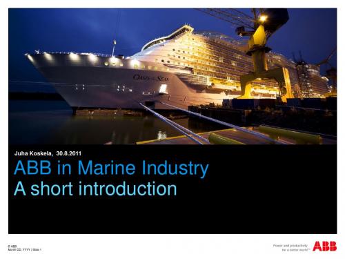
Electric power plant & propulsion Azipod@ propulsors and thrusters Drives for offshore oil drilling process Automation and electrification for Harbor cranes
Vessel information and control Proven systems for marine applications Quality components with service and support available throughout their lifecycle.
powering LNG carriers into new era of energy efficiency installed in more than 125 offshore drilling rigs and jack ups
© ABB Group July 27, 2013 | Slide 3
Finland, Norway, China and Singapore
© ABB Group July 27, 2013 | Slide 2
Moving people and goods safely and efficiently You will find ABB marine solutions
•
•
•
Electric propulsion
•
Diesel-Generator setsfor propulsion and ship use
浅谈AZIPOD推进装置船上安装
-35-作者简介:刘明栋(1991--),男,助理工程师,轮机工程。
陈晓俊(1985--),男,工程师,轮机工程。
杨梅(1966--),女,高级工程师,船舶舾装工艺。
卫作驹(1960--),男,高级技师,轮机工程。
浅谈AZIPOD 推进装置船上安装刘明栋陈晓俊杨梅卫作驹(广船国际总装一部、技术中心)摘要:本文以全球首艘极地凝析油轮的AZIPOD 推进装置船上安装作为研究对象,对安装工程的难、重点进行分析,为后续类似船舶建造提供参考。
关键词:转舵模块;推进模块;法兰DOI :10.3969/j.issn.2095-4506.2020.04.0110前言44500DWT Arc7冰区级极地凝析油轮是广船国际为希腊Dynacom 公司建造的全球首艘吊舱推进、双向破冰凝析油运输船,配备2套AZIPOD 推进装置,型号为VI2300-I4000H6。
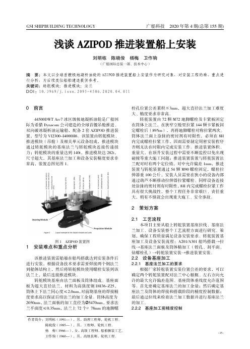
该装置由转舵模块、推进模块(吊舱)及相关单元设备组成,推进模块通过转舵模块的基座法兰与转舵模块连接传递扭力;转舵模块的重量达到140t,推进模块达282t,尺寸超大,其基座法兰加工和设备安装精度要求非常高,装置总图见图1。
图1AZIPOD 装置图1安装难点和重点分析该推进装置需船舶在船坞搭载达到安装条件后进行安装,根据设备技术要求需要焊接两个钢法兰到船体结构上,然后将转舵模块使用螺栓安装到该法兰上,最后连接推进模块。
转舵模块基座由法兰面板及筒体组成。
基座面板为超大直径法兰,材料为高强度钢DH36-Z25,筒体上下法兰同心度≤2.0mm,对前期基座的焊接精度要求高以保证后续法兰的加工余量。
筒体高度为2050mm,法兰面板的加工直径为Ø5470mm,要求法兰平面度≤0.35mm,法兰上72个∅78mm 的地脚螺栓孔位置公差累积≦3mm,超大直径法兰加工难度大、精度要求非常高。
转舵装置由72颗M72地脚螺栓及卡紧板固定在筒体上法兰,在狭窄空舱里拉紧144颗卡紧板固定螺栓后(89Nm),再将地脚螺栓对称拉紧两次。
水下推进器技术说明

水下推进器技术说明水下推进器主要用在厌氧池中,对池内半液态的污泥进行搅拌混合,保持污泥不沉淀,也可用在氧化沟等形式的曝气池中,解决普通曝气器充氧与推流作用的矛盾,还可用在均质池中,促进出水水质的均匀和防止有机杂质在均质中的沉淀。
(1)结构特点水下推进器由电机、减速箱、轮毂、叶片组成,叶轮直径为1100~2500mm,转速为38~47r/min。
水下推进器利用一根不锈钢方管作为导向杆,导向杆对水下推进器进行定位和提供支撑,一般通过安装在操作平台上的手动绞盘提升到水面以上的检修平台进行检修。
为了对水下推进器进行有效监控,一般在定子内安装温度传感器,温度大于125℃时电机可以自动断电停止运转;在减速箱前的油箱内配有湿度传感器,油室内水分达到10%时,可以发出警报并自动断电。
水下推进器电机的绝缘等级为F级,依靠四周的污水或污泥进行冷却,电缆与接线盒入口密封使用专用橡胶结构密封,其他密封处使用O 形圈加不干性密封胶进行密封。
减速箱与电机连在一起,采用两级齿轮减速机构,结构紧凑,第一级的小齿轮在电机输出轴上直接加工而成。
减速箱前部设置密封油室,输出轴贯穿油室,为防止污水进入池室,输出轴出油室的部位使用机械密封。
水下推进器的轮毂直接套在减速箱的输出轴上,使用平键实现动力传递。
为防止轮毂的轴向窜动,在输出轴顶端用螺栓压紧盖板阻止轮毂外窜,向内轴向窜动由输出轴上的轴肩来完成。
水下推进器有两只向后弯的叶片,其骨架为钢质,外表覆盖既耐腐蚀、又具有很好强度和刚度的工程塑料,叶片后弯可以起到防缠绕和减小反作用力的双重作用。
(2)使用和维护注意事项①水下推进器安装前,要检查接线是否正确,防止叶片反转,还要认真检查减速箱和油室内的油质和油位是否正确,同时要保证各紧固件正确紧固,尤其要注意电机接线盒上的入口处密封是否完好。
无水试运转的时间不能超过3min。
②水下推进器的安装深度必须保证叶片的最高点到水面的距离大于0.8m。
③及时清理干净积存在提升钢丝绳上的垃圾,每个月都要对吊环、吊环扣及钢丝绳上的磨损情况进行检查,并根据磨损程度随时更换。
中国海监83号船的ABB电力推进系统
频器 直接 供 电 。 由变 频 器 控 制 永 磁 同步 电机 , 电机
转 速 0 2 8p ; ~ 8rm
整个 电站 由功率 管理 系统 P MS自动监控 , 时 随
保 证 推 进 及 船 舶 电 网安 全 所 需 ; 配 置 推 进 操 纵 和 控 制 的 驾 驶 室 控 制 板 和 仪 表板 ;
符 合 S AS公 约 要 求 。 0L ( ) 回 转 吊舱 式 电 力 推 进 系 统 加 上 双 艏 部 侧 6全 推 器 , 使 监 察 船 艏 艉 均 可 迅 速 获 得 横 向 推 力 , 足 可 满
站系 统 和主推 进 系统 两部 分组 成 。每 一 推进 系统 配
置 发 电 机 、9 V 低 压 配 电 板 、 电 变 压 器 、 频 器 、 60 供 变
提 要 中 国 海 监 8 3号 船 的 AB 电 力 推 进 系 统 B
推 进 系 统 通 过 6 0 电 网 向 AC 6 0水 冷 式 变 9V S0
由 电站 系统 和 主推 进 系统 两部 分 组 成 。介 绍 了 该 系统 的 配 置 以及 操 纵 性 能 和 运 行 的 经 济 性 。 并 对 实船 测 得 的 振 动 和 噪 声数 据 进 行 了对 比 、 析 与 评 价 。 分
一
定位 系 统 的 30 0吨级 综合 海洋 监 察船 。 0
2 全 回转 吊舱 式 电力 推 进 系 统 典 型 配 置
( ) 国海监 8 1中 3号 的 AB 电 力 推 进 系 统 由 电 B
方 向 由零 至 全 速 间 无 级 平 滑 变 速 , 力 通 过 3 O 电 6。
的滑 环传 输 给 推进 电动 机 ; 装 在 舵 浆 舱 内 的转 舵 安 模块 含 2台转舵 电机 及供 电变 频 器 , 分别 由主 、 急 应 电源 供 电 , 实现 3 0全 回转 ; 电源 和操舵 装 置均 可 6。 主
中国海洋科考船装备ABB电力推进系统

中国海洋科考船装备ABB电力推进系统
佚名
【期刊名称】《电气制造》
【年(卷),期】2010(000)006
【摘要】全球领先的电力和自动化技术集团ABB近日宣布,中国自主设计并制造的深海海洋科学综合考察船将采用ABB先进的Azipod吊舱式电力推进系统,大幅提高船舶燃油效率,显著降低废气排放。
【总页数】1页(P12-12)
【正文语种】中文
【中图分类】U664.3
【相关文献】
1.中国科考船装备ABB电力推进系统 [J],
2.直流电力推进系统在小水线面双体科考船上的应用 [J], 李鸿瑞;熊良胜;邵诗逸
3.直流电站电力推进系统在小水线面双体科考船中的应用 [J], 李明刚;袁毓
4.我国科考船装备Azipod吊舱式电力推进系统 [J],
5.中国科考船装备ABB电力推进系统 [J],
因版权原因,仅展示原文概要,查看原文内容请购买。
- 1、下载文档前请自行甄别文档内容的完整性,平台不提供额外的编辑、内容补充、找答案等附加服务。
- 2、"仅部分预览"的文档,不可在线预览部分如存在完整性等问题,可反馈申请退款(可完整预览的文档不适用该条件!)。
- 3、如文档侵犯您的权益,请联系客服反馈,我们会尽快为您处理(人工客服工作时间:9:00-18:30)。
Deep water installation to drill ship Deep water installation to semi-submersibles ”Mud plate” installation for shallow water
Internal installations are very simple and fast to do
2.
3.
4.
1.
2.
3. & 4.
© ABB Oy, Marine & Turbocharging, 2011 8
Installation Drill Ship – Deep Water
- Main principle: Step 2
1.
The diver re-connects the three strand jack fixed anchor assemblies to the Azipods three prerigged guide wires. The operations manager instructs the crane operator to recover the auxiliary hoist and rigging. The diver instructs the crane operator to begin lowering the Azipod in increments until the weight starts to come onto the strand jack cables. At any time during the above sequence and at the discretion of the diver and operations manager. Provided that the crane wire is clear of the vessel and the angle of the strand jack cables is acceptable then the internal jacking crew can be instructed to start raising the Azipod.
© ABB Oy, Marine & Turbocharging, 2011 6
Lifting – Complete Unit
Azipod CZ1400L – 4500kW
Weight in air 71,5tons No need for special transport or lifting cradles Single lifting Well balanced Lifting points
Veli-Pekka Peljo 2011-06-21
Azipod CZ1400L UW Installation to a Vessel
© ABB Oy, Marine & Turbocharging, 2011 1
ABB Azipod CZ1400L Thruster Installation
© ABB Oy, Marine & Turbocharging, 2011 5 © ABB Group March 29, 2012 | Slide 5
Azipod CZ Strand Jack Arrangement (example)
Jacking room Azipod room
This study is based on following makers technology: Dorman Long Technology Jacks 3 × DL-S46, Power Pack DL-L-15/4/300/E (non ABB delivery)
© ABB Oy, Marine & Turbocharging, 2011 3
Azipod CZ Lifting Points
Single point lifting points B & D SWL 80 ton C2 D C1 C3 D C3 B C1 B 3-point lifting points C1, C2 & C3 SWL 35 ton
ABB Azipod type CZ thrusters can be installed underwater Basic principle of the installation method is well proven and typical also for other types of thrusters. Installation depth max 50m ABB have guidelines for following installation methods:
Installation Drill Ship – Deep Water
- Main principle: Step 1
1.
The Azipod is pre-rigged on the deck with the short guide wires in place on the three lifting points. The pair of main lift wires can be attached to the delta plate on the strut and on the nozzle. With the diver remaining clear of the lift but at a visual vantage point for monitoring the decent the operations manager instructs the crane operator to lower the Azipod to a water depth of approximately 32m. The operations manager instructs the crane operator to lower the crane auxiliary hoist and rigging (hanging off wires) to the diver. The diver connects the cranes auxiliary hoist rigging to the three strand jack fixed anchor assemblies.
© ABB Oy, Marine & Turbocharging, 2011 2 © ABB Group March 29, 2012 | Slide 2
Introduction f thruster change out procedure
ABB provides document Generic Underwater Removal and Installation Procedures (SPL) for shipyard to adapt it on their own use. Document describes the basic idea and procedure for underwater change out for ABB Azipod CZ thruster. Described procedure is for guidance only and will not be vessel specific. Generic procedure is related primarily to Drill ships but can be adopted for use with Semi Submersibles. The procedure assumes that the vessels own cranes are suitable for purpose, can reach both sides of the vessel fore and aft and are rated over and above the thrusters dry weight of Azipod CZ should the vessel cranes not be rated for or capable of reaching the work site then a floating crane barge will need to be assigned. Water depths shown in the sequence drawings are for guidance only as depths will be dependent on vessel size, draught and the reach of the crane. In all cases the maximum depth must not exceed 50meters. Generic Underwater Removal and Installation Procedures (SPL) describes External Underwater procedure only and it is assumed that the Internal preparations in Azipod CZ Internal Installation has been completed and that the thruster is ready to be removed. ABB will provide also Installation checklist document containing a checklist that should be completed at each relevant stage of the operation. The Drill ship will need to be at anchor during this procedure with all thrusters stopped and isolated. Process described in the document covers actions for a number of parties and responsibilities of the actions must be agreed in every case. Presented process is recommended by ABB. The lifting equipment and rigging discussed in the document is for guidance only and ultimately is the responsibility of the shipyard and or vessels owner.
