Abaqus划分网格技巧小结
ABAQUS 划分网格的方法(读书总结)

划分网格的方1.独立实体(independent instance)和非独立实体(dependent instance)对非独立实体划分网格时,应在窗口顶部的环境栏中把Object选项设为part,即对部件划分网格;对独立实体划分网格时, 应在窗口顶部的环境栏中把Object选项设为assembly,即对装配件划分网格2.网格单元形状在MESH功能模块中,Mesh—Controls,弹出Mesh Controls对话框,其中可选择单元形状。
2D问题,有以下可供选择的单元形状。
1)Quad:网格中完全使用四边形单元;2)Quad-dominated:网格中主要使用四边形单元,但在过渡区域允许出现三角形单元。
选择Quad-dominated类型更容易实现从粗网格到细网格的过渡;3)Tri:网格中完全使用三角形单元;对于3D问题,包括以下可供选择的单元形状:1)Hex:网格中完全使用六面体单元;2)Hex-dominated:网格中主要使用六面体单元,但在过渡区域允许出现楔形(三棱柱)单元;3)Tet:网格中完全使用四面体单元;4)Wedge:网格中完全使用楔形单元;Quad(2D问题)和Hex(3D问题)可以用较小的计算代价得到较高的精度,应尽可能选择这两种单元。
3.网格划分技术Structured(结构化网格):采用结构化网格的区域显示为绿色;Sweep(扫掠网格):采用扫掠网格的区域显示为黄色;Free(自由网格):采用自由网格的区域显示为粉红色;自由网格技术采用Tri和Tet,一般应选择带内部节点的二次单元来保证精度;结构化网格和扫掠网格一般采用Quad和Hex单元,分析精度相对较高。
4.划分网格的算法使用Quad和Hex单元划分网格时,有两种可供选择的算法:Medial Axis(中性轴算法)和Advancing Front(进阶算法)。
Medial Axis(中性轴算法):首先把要划分网格的区域分成一些简单的区域,然后使用结构化网格划分技术来为简单区域划分网格。
ABAQUS 网格技术(孤立网格、网格划分)

– 本例输入的机械部件已经采用一阶四面 体单元划分完毕。
ABAQUS/CAE_孤立网格
• 将一阶单元转为二阶,或将二阶单元转为 一阶
• 对平面、三角形孤立网格进行网格重划分。
用于处理不良几何形状的更加 高级的网格编辑工具在 “ABAQUS/CAE: Geometry Import and Meshing” 讲座中有 更详细的介绍
L6.14
ABAQUS/CAE_孤立网格
导入孤立网格
• 移动节点 – 用户可以指定任意一种移动节点的方法: • 新的坐标 • 在任意坐标系中,坐标的改变 (偏置) δx, δy, δz, δr, δθ, 等等。 – 在不需要重新选择节点的前提下,可以进行连续的增量变化。 – 创建单元 – Tip(提示)按钮将显示选定单元形状的节点顺序。 – 检测无效的单元。
ABAQUS/CAE_孤立网格
历程数据以第一个 *STEP 选 项开始
历程数据以最后一个*END STEP选项结束
L6.9
导入孤立网格
– 可以通过ABAQUS输入文件(.inp) 或输出数据库文件(.odb)导入已有 网格。
– 被导入的网格称“孤立网格”,因 为它没有父几何体。
ABAQUS/CAE_孤立网格
– 模型数据
该行将会出现在每个输出页上。
*HEADING
CANTILEVER BEAM EXAMPLE
UNITS IN MM, N, MPa
*NODE
总结Abaqus操作技巧总结(个人)

总结Abaqus操作技巧总结(个人)Abaqus操作技巧总结打开abaqus,然后点击file——set work directory,然后选择指定文件夹,开始建模,建模完成后及时保存,在进行运算以前对已经完成的工作保存,然后点击job,修改inp文件的名称进行运算。
切记切记1、如何显示梁截面(如何显示三维梁模型)显示梁截面:view->assembly display option->render beam profiles,自己调节系数。
2、建立几何模型草绘sketch的时候,发现画布尺寸太小了1)这个在create part的时候就有approximate size,你可以定义合适的(比你的定性尺寸大一倍);2)如果你已经在sketch了,可以在edit菜单--sketch option ——general --grid更改3、如何更改草图精度可以在edit菜单--sketch option ——dimensions--display——decimal更改如果想调整草图网格的疏密,可以在edit菜单--sketch option ——general——grid spacing中可以修改。
4、想输出几何模型part步,file,outport--part5、想导入几何模型?part步,file,import--part6、如何定义局部坐标系Tool-Create Datum-CSYS--建立坐标系方式--选择直角坐标系or柱坐标系or球坐标7、如何在局部坐标系定义载荷laod--Edit load--CSYS-Edit(在BC中同理)选用你定义的局部坐标系8、怎么知道模型单元数目(一共有多少个单元)在mesh步,mesh verify可以查到单元类型,数目以及单元质量一目了然,可以在下面的命令行中查看单元数。
Query---element 也可以查询的。
9、想隐藏一些part以便更清楚的看见其他part,edge等view-Assembly Display Options——instance,打勾10、想打印或者保存图片File——print——file——TIFF——OK11、如何更改CAE界面默认颜色view->Grahphic options->viewport Background->Solid->choose the wite colour!然后在file->save options.12、如何施加静水压力hydrostaticload --> Pressure, 把默认的uniform 改为hydrostatic。
abaqus圆形区域划分网格

abaqus圆形区域划分网格在有限元分析中,abaqus是一个常用的有限元软件,能够对复杂结构进行力学性能的分析。
对于圆形区域的网格划分,在abaqus中也可以轻松实现。
本文将介绍如何在abaqus中将圆形区域进行网格划分的方法和步骤。
步骤一:创建圆形区域要在abaqus中划分圆形区域的网格,首先需要创建一个圆形的几何实体。
可以按照以下步骤操作:1.打开abaqus软件并创建一个新模型。
2.在Part模块中选择“Sketch”工具,进入绘图界面。
3.在绘图界面上选择“Circle”工具,然后在工作平面上绘制一个圆形。
4.输入圆的半径和圆心坐标等参数,调整圆的大小和位置以适应实际应用需求。
5.确认圆形的位置和大小后,退出绘图界面。
步骤二:划分网格一旦创建了圆形几何实体,下一步就是对其进行网格划分。
下面是划分网格的具体步骤:1.在Part模块中选择“Mesh”工具,进入网格划分界面。
2.在网格划分界面中,选择圆形几何实体。
可以使用鼠标单击选取,或者输入圆形实体的名称来选中它。
3.在选中圆形实体后,选择合适的网格划分方法。
abaqus提供了多种网格划分算法,如大小相等的正方形单元格划分、网格密度逐渐变化的方法等。
根据具体需求选择合适的网格划分方法。
4.调整网格划分参数。
可以通过调整参数来控制网格的细密程度和分辨率。
例如,可以调整单元格大小、单元格数量和网格密度等参数。
5.确认网格划分参数后,点击“Generate”按钮,abaqus将自动生成所需的网格划分。
步骤三:查看和修改网格在完成网格划分后,可以查看生成的网格,并根据需要进行进一步的修改和优化。
以下是查看和修改网格的操作步骤:1.转到网格模块,选择“Mesh”工具,进入网格划分界面。
2.在网格划分界面中,选择“Display Options”工具,调整显示选项。
可以选择显示节点、单元格、边界等,以便更好地了解网格的结构和分布情况。
3.查看网格划分结果,并根据需要进行修改。
abaqus技巧

三维结构的结构化网格划分structure 对于三维结构,只有模型区域满足以下条件,才能被划分为结构化网格:①没有孔洞、孤立的面、孤立的边、孤立的点;②面和边上的弧度值应该小于90°;③三维区域内的所有面必须要保证可以运用二维结构化网格划分方法;④保证区域内的每个顶点属于三条边;⑤必须保证至少有四个面(如果包含虚拟拓扑,必须仅包含六条边);⑥各面之间要尽可能地接近90°,如果面之间的角大于150°,就应该对它进行分割;⑦若三维区域不是立方体,每个面只能包含一个小面,若三维区域是立方体,每个面可以包含一些小面,但每个小面仅有四条边,且面被划分为规则的网格形状。
三维结构的扫略网格划分Sweep (扫略网格划分技术)对于三维结构,只有模型区域满足以下条件,才能被划分为扫略网格:①连接起始面和目标面的的每个面(称为连接面)只能包含一个小面,且不能含有孤立的边或点;②目标面必须仅包含一个小面,且没有孤立的边或点;③若起始面包含两个及两个以上的小面,则这些小面间的角度应该接近180°;④每个连接面应由四条边组成,边之间的角度应接近90°;⑤每个连接面与起始面、目标面之间的角度应接近90°;⑥如果旋转体区域与旋转轴相交,就不能使用扫略网格划分技术;⑦如果被划分区域的一条或多条边位于旋转轴上,ABAQUS/CAE不能用六面体或楔形单元对该区域进行扫略网格划分,而必须选择Hex—dominated形状的单元;⑧当扫略路径是一条封闭的样条曲线时,该样条曲线必须被分割为两段或更多。
总结(1 )对于不能采用结构化技术(Structured)和扫略技术(Sweep )进行网格划分的复杂结构,用户可以运用Partition 工具将其分割成形状较为简单的区域,并对这些区域进行结构化或扫略网格划分.如果模型不容易分割或分割过程过于繁杂,用户可以选用自由网格划分技术(Free )。
[精品]abaqus网格划分技巧
![[精品]abaqus网格划分技巧](https://img.taocdn.com/s3/m/9de7060afd4ffe4733687e21af45b307e871f9f3.png)
划分网格是有限元模型的一个重要环节,它要求考虑的问题较多,工作量较大,所划分的网格形式由于划分者的水平和思路不同而有很大的差异,因而对计算精度和计算规模会产生显著的影响。
有限元网格数量的多少和质量的好坏直接影响到计算结果的精度和计算规模的大小。
一般来讲,网格数量增加,计算精度会有所提高,但同时计算规模也会增加,所以在确定网格数量时应该权衡这两个参数。
网格较少时增加网格数量可以显著提高计算精度,而计算时间不会有很大的增加。
所以应注意增加网格数量后的经济性。
实际应用时可以比较疏密两种网格划分的计算结果,如果两种计算结果相差较大,应该继续增加网格,重新计算,直到误差在允许的范围之内。
ABAQUS中的网格划分方法应该是所有通用有限元分析软件中最强大的。
介绍一下网格划分技术,包括:结构化网格、扫掠网格、自由网格:1)结构化网格技术(STRUCTURED):将一些标准的网格模式应用于一些形状简单的几何区域,采用结构化网格的区域会显示为绿色(不同的网格划分技术会对相应的划分区域显示特有的颜色标示)。
2)扫掠网格技术(SWEEP):对于二维区域,首先在边上生成网格,然后沿着扫掠路径拉伸,得到二维网格;对于三维区域,首先在面上生成网格,然后沿扫掠路径拉伸,得到三维网格。
采用扫掠网格的区域显示为黄色。
3)自由网格划分技术(FREE):自由网格是最为灵活的网格划分技术,几乎可以用于任何几何形状。
采用自由网格的区域显示为粉红色。
自由网格采用三角形单元(二维模型)和四面体单元(三维模型),一般应选择带内部节点的二次单元来保证精度。
4)不能划分网格:如果某个区域显示为橙色,表明无法使用目前赋予它的网格划分技术来生成网格。
这种情况多出现在模型结构非常复杂的时候,这时候需要把复杂区域分割成几个形状简单的区域,然后在划分结构化网格或扫掠网格。
注意:使用结构化网格或扫掠网格划分技术时,如果定义了受完全约束的种子(SEED),网格划分可能不成功,这时会出现错误信息们,可以忽略错误信息,允许ABAQUS去除对这些种子的约束,从而完成对网格的划分。
ABAQUS常用技巧归纳图文并茂
ABAQUS常用技巧归纳图文并茂ABAQUS常用技巧归纳一、背景介绍ABAQUS是一款广泛应用于工程领域的有限元分析软件,具备强大的功能和丰富的工具包,被工程师广泛使用。
然而,在使用ABAQUS的过程中,我们经常会遇到一些技巧和问题,本文将针对一些常见的ABAQUS技巧进行归纳总结,帮助读者更好地应用ABAQUS进行工程分析。
二、常用技巧1. 单元类型选择在使用ABAQUS进行有限元分析时,选择合适的单元类型是非常重要的。
根据具体的分析对象和问题类型,可以选择不同的单元类型,如线性单元、非线性单元或复合单元。
合理的单元选择可以提高计算效率和分析精度。
2. 网格划分优化合理的网格划分对计算结果的准确性和计算效率至关重要。
在ABAQUS中,提供了多个网格划分工具和算法,可以帮助用户进行网格优化。
例如,使用网格生成工具可以自动生成符合几何形状和尺寸要求的网格,使用网格划分工具可以调整网格的密度和精度。
3. 材料模型选择在ABAQUS中,提供了多种材料模型,用于描述材料的力学行为。
根据具体的分析对象和材料性质,可以选择合适的材料模型,如线性弹性模型、塑性模型或粘弹性模型。
合理的材料模型选择可以更好地模拟材料的本构行为。
4. 边界条件设置在有限元分析中,正确设置边界条件是保证结果准确性的关键。
在ABAQUS中,可以通过节点约束、荷载施加和接触定义等方式来设置边界条件。
应根据具体的分析问题和工况设置合理的边界条件,以确保计算结果的可靠性。
5. 后处理及结果分析ABAQUS提供了强大的后处理和结果分析功能,可以帮助用户深入理解计算结果。
通过后处理工具,可以对计算结果进行可视化分析、曲线绘制和云图展示等,帮助用户对结果进行全面的评估和解读。
6. 自定义脚本开发除了使用ABAQUS内置的工具和功能,用户还可以通过编写脚本来定制化分析过程。
ABAQUS支持Python脚本的开发和调用,用户可以利用脚本进行批处理、参数化分析和复杂算法实现等。
ABAQUS 单元总结与分析技巧

abaqus单元小结[zz]默认分类2009-04-28 20:37 阅读53 评论0 字号:大大中中小小1、单元表征单元族:单元名字里开始的字母标志着这种单元属于哪一个单元族。
C3D8I是实体单元;S4R是壳单元;CINPE4是无限元;梁单元;刚体单元;膜单元;特殊目的单元,例如弹簧,粘壶和质量;桁架单元。
自由度dof(和单元族直接相关):每一节点处的平动和转动1 1方向的平动2 2方向的平动3 3方向的平动4 绕1轴的转动5 绕2轴的转动6 绕3轴的转动7 开口截面梁单元的翘曲8 声压或孔隙压力9 电势11 度(或物质扩散分析中归一化浓度)12+梁和壳厚度上其它点的温度轴对称单元1 r方向的平动2 z方向的平动6 r-z方向的转动节点数:决定单元插值的阶数数学描述:定义单元行为的数学理论积分:应用数值方法在每一单元的体积上对不同的变量进行积分。
大部分单元采用高斯积分方法计算单元内每一高斯点处的材料响应。
单元末尾用字母“R”识别减缩积分单元,否则是全积分单元。
ABAQUS拥有广泛适用于结构应用的庞大单元库。
单元类型的选择对模拟计算的精度和效率有重大的影响;节点的有效自由度依赖于此节点所在的单元类型;单元的名字完整地标明了单元族、单元的数学描述、节点数及积分类型;所用的单元都必须指定单元性质选项。
单元性质选项不仅用来提供定义单元几何形状的附加数据,而且用来识别相关的材料性质定义;对于实体单元,ABAQUS参考整体笛卡尔坐标系来定义单元的输出变量,如应力和应变。
可以用*ORIENTATION选项将整体坐标系改为局部坐标系;对于三维壳单元,ABAQUS参考建立在壳表面上的一个坐标系来定义单元的输出变量。
可以用*ORIENTATION选项更改这个参考坐标系。
2.实体单元(C)实体单元可在其任何表面与其他单元连接起来。
C3D:三维单元CAX:无扭曲轴对称单元,模拟3600的环,用于分析受轴对称载荷作用,具有轴对称几何形状的结构;CPE:平面应变单元,假定离面应变ε33为零,用力模拟厚结构;CPS:平面应力单元,假定离面应力σ33为零,用力模拟薄结构;广义平面应变单元包括附加的推广:离面应变可以随着模型平面内的位置线性变化。
abaqus网格划分技巧

abaqus网格划分技巧
1、局部细化:在计算模型中需要更多的分析精度的地方,可以进行局部细化,采用不同的网格大小来满足模型的要求。
2、结构网格划分:在结构分析中,要求网格能够有效地表征出模型中结构物体的形状。
通常使用拓扑结构、均匀结构或者混合结构网格来实现这一目的。
3、等边三角剖分:等边三角剖分是一种常见的划分网格的方法,其优点是能够保证网格节点的质量。
4、自动划分:对于复杂的网格,可以使用abaqus自动划分网格功能来自动生成网格,以达到良好的精度和节点质量。
abaqus网格划分
abaqus网格划分如何使用3D实体单元?1 如果不需要模拟非常大的应变或进行一个复杂的、改变接触条件的问题,则应采用二次减缩积分单元(CAX8R,CRE8R,CPS8R.C3D20R等)。
2 如果存在应力集中,则应在局部采用二次完全积分单元(CAX8,CPE8,CPS8,C3D20等)。
它们可在较低费用下对应力梯度提供最好的解决。
尽量不要使用线性减缩积分单元。
用细化的二次减缩积分单元与二次完全积分单元求解结果相差不大,且前者时间短。
3 对含有非常大的网格扭曲模拟(大应变分析),采用细网格划分的线性减缩积分单元(CAX4R,CPE4R.CPS4R,C3D8R等)。
4 对接触问题采用线性减缩积分单元或非协调单元(CAX4I,CPE4I,CPS4II,C3D8I等)的细网格划分。
5 对以弯曲为主的问题,如能保证所关心部位单元扭曲较小,使用非协调单元(如C3D8I),求解很精确。
6 对于弹塑性分析,不可压缩材料(如金属),不能使用二次完全积分单元,否则易体积自锁,应使用修正的二次三角形或四面体单元、非协调单元,以及线性减缩积分单元。
若使用二次减缩积分单元,当应变超过20%-40%要划分足够密的网格。
7 除平面应力问题之外,如材料完全不可压缩(如橡胶),应使用杂交单元;在某些情况下,近似不可压缩材料也应使用杂交单元。
8 当几何形状复杂时,万不得已采用楔形和四面体单元。
这些单元的线性形式,如C3D6和C3D4,是较差的单元(若需要时,划分较细的网格以使结果达到合理的精度),这些单元也应远离需要精确求解的区域。
9 如使用了自由网格划分技术,四面体单元应选二次的,其结果对小位移问题应该是合理的,但花时间多。
在ABAQUS/Standard中选C3D10,ABAQUS/Explicit中选修正的(C3D10M)。
如有大的塑性变形,或模型中存在接触,且使用默认的“硬”接触关系,也应选C3D10M。
10 ABAQUS/Explicit模拟冲击或爆炸,应选线性单元。
典型零件ABAQUS 网格划分
ABAQUS 网格划分经典总结ABAQUS是大型通用的有限元分析软件,其强大的功能是对非线性的处理优于其他同类软件。
它的网格划分功能,可以说是相当强的,当然这得掌握其中奥秘。
运用合理,不亚于专业的网格划分软件,比如HM和ADINA,甚至比专业划分软件更优越和快捷。
本人对ABAQUS 网格划分的研究思路来源于HM的网格划分思路,也借鉴了NASTRAN的网格划分思路。
现在深知知识面广泛的重要性,每个软件都有它独当一面的地方,也有它不足之处,我们可以借鉴、学习其他软件的优点,并将优点运用于同类软件,弥补各类软件之不足。
综合运用各软件的优点,来达到优势互补,熟能生巧,巧能通精的目的。
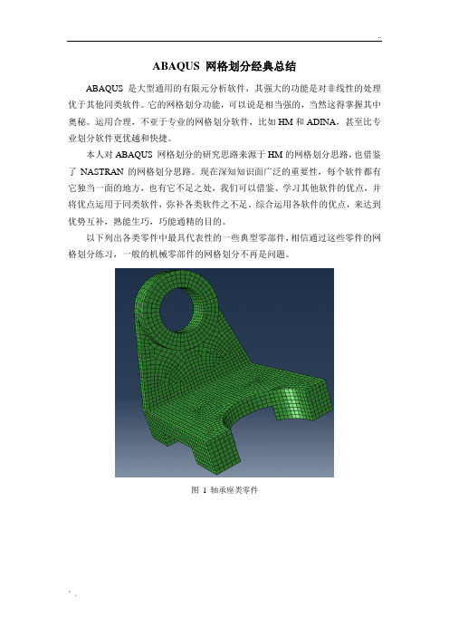
以下列出各类零件中最具代表性的一些典型零部件,相信通过这些零件的网格划分练习,一般的机械零部件的网格划分不再是问题。
图 1 轴承座类零件图 2 多支耳类零件图 3 箱体类零件图 4 空心圆柱与箱体组合零件图 5 环形槽类零件图 6.1 支耳、空心圆柱、空心长方体组合零件图6.2支耳、空心圆柱、空心长方体组合零件图7.1 类齿轮零件图7.2类齿轮零件这类零件的网格划分,ABAQUS确实不如HM优越,HM先在一个片体上进行网格划分,然后使用spin功能,进行旋转,很容易得到网格质量比较高的网格模型,而ABAQUS需要经过多次剖切才能得到网格质量较高的模型。
图8.1 剖切后网格控制显示剖切后,颜色显示为黄色和绿色,能用结构化和扫略网格划分技术。
如果网格划分质量较差,可以使用ABAQUS独到的短边、小面检查功能,不难发现,网格质量差的原因是存在短边、小面,这时ABAQUS的虚拟拓扑功能方能解决此问题。
使用虚拟拓扑后,网格划分质量是相对较高的。
如果有尖锐角度存在,这时可根据需要要适当使用一些四面体单元。
图8.2 网格完成后模型图9 相切空心圆柱模型图10 组合零件1图10 组合零件组合体总结思考复杂的模型也是由简单模型构成的,熟悉了简单模型的网格划分,复杂模型的高质量网格创建也就迎刃而解了。
abaqus技巧窍门

三维结构的结构化网格划分structure 对于三维结构,只有模型区域满足以下条件,才能被划分为结构化网格:①没有孔洞、孤立的面、孤立的边、孤立的点;②面和边上的弧度值应该小于90°;③三维区域内的所有面必须要保证可以运用二维结构化网格划分方法;④保证区域内的每个顶点属于三条边;⑤必须保证至少有四个面(如果包含虚拟拓扑,必须仅包含六条边);⑥各面之间要尽可能地接近90°,如果面之间的角大于150°,就应该对它进行分割;⑦若三维区域不是立方体,每个面只能包含一个小面,若三维区域是立方体,每个面可以包含一些小面,但每个小面仅有四条边,且面被划分为规则的网格形状。
三维结构的扫略网格划分Sweep (扫略网格划分技术)对于三维结构,只有模型区域满足以下条件,才能被划分为扫略网格:①连接起始面和目标面的的每个面(称为连接面)只能包含一个小面,且不能含有孤立的边或点;②目标面必须仅包含一个小面,且没有孤立的边或点;③若起始面包含两个及两个以上的小面,则这些小面间的角度应该接近180°;④每个连接面应由四条边组成,边之间的角度应接近90°;⑤每个连接面与起始面、目标面之间的角度应接近90°;⑥如果旋转体区域与旋转轴相交,就不能使用扫略网格划分技术;⑦如果被划分区域的一条或多条边位于旋转轴上,ABAQUS/CAE不能用六面体或楔形单元对该区域进行扫略网格划分,而必须选择Hex-dominated形状的单元;⑧当扫略路径是一条封闭的样条曲线时,该样条曲线必须被分割为两段或更多。
总结(1 )对于不能采用结构化技术(Structured)和扫略技术(Sweep )进行网格划分的复杂结构,用户可以运用Partition 工具将其分割成形状较为简单的区域,并对这些区域进行结构化或扫略网格划分。
如果模型不容易分割或分割过程过于繁杂,用户可以选用自由网格划分技术(Free )。
ABAQUS学习技巧总结
ABAQUS学习技巧总结1.加强对有限元理论的学习:ABAQUS是一种基于有限元方法的强大分析软件,因此要充分理解有限元理论的基本原理和假设,才能正确应用ABAQUS进行分析和模拟。
2.熟练掌握ABAQUS的使用界面:学习ABAQUS前,首先要了解软件的界面和基本操作,包括创建模型、定义材料、设置边界条件、网格划分等操作。
熟悉软件界面可以提高工作效率和减少出错的可能性。
3.控制模型精度和网格划分:模型的精度和网格的划分对分析结果的准确性和计算效率有着重要影响。
在进行模型划分时,要根据分析对象的特点和要求合理设定网格密度,避免过度细化或过度简化。
4.学会使用参数化建模:ABAQUS支持参数化建模,可以通过定义参数和变量来快速修改模型的几何形状和尺寸。
掌握参数化建模技巧可以快速生成不同几何形状和尺寸的模型,并进行参数优化和灵敏度分析。
5.熟悉材料模型的选择和参数设置:ABAQUS提供了多种材料模型,如线性弹性模型、塑性模型、粘弹性模型等。
根据不同材料的特性和分析要求选择适当的材料模型,并设置合理的参数值。
6.学会使用边界条件和荷载:在进行分析前,要定义好模型的边界条件和施加的荷载。
合理设置边界条件和荷载可以减少计算量和提高计算效率,并得到准确的分析结果。
7.了解并理解结果输出和后处理:ABAQUS可以输出各种工程量的结果,如应力、应变、位移、等效塑性应变等。
了解和理解结果输出的含义和格式,可以进行有效的后处理和结果分析。
8.学会使用预处理和后处理工具:ABAQUS提供了多种预处理和后处理工具,如网格生成、模型修复、网格平滑、结果可视化等。
学会使用这些工具可以提高工作效率和优化分析结果。
9. 提高编程和脚本能力:ABAQUS提供了Python编程接口,可以通过编写脚本进行批处理、自动化建模和分析。
提高编程和脚本能力可以进一步提高工作效率和掌握高级分析技巧。
10.学会查阅文档和使用技术支持:ABAQUS的官方网站提供了丰富的文档和教程,可以帮助学习者更好地了解和使用软件。
abaqus个人总结

1、部件为橙色时,表明为非独立实体,无法使用默认的网格划分技术来生成网格,需要首先把部件分为几个简单的区域,然后再每个区域上分别生成结构网格或者扫掠网格;2、部件区域为黄色时,表明可以生成扫掠网格;3、部件区域为绿色时,表明可以划分结构网格;4、分割面或者分割体的步骤:先切换到网格功能模块,将对象选为部件,然后点击左侧工具区的拆分面等拆分工具,选中要分割的对象,点击鼠标中键进入绘图环境,若提示将删除已有的网格,OK即可;分割后可以通过点击“为部件划分网格”,之后在视图区点击鼠标中键,重新生成网格;5、abaqus运行时出现错误:GUI detected error while waiting for ipc connection to close。
原因:ABAQUS对显卡硬件加速有要求方法一:1,打开电脑。
2、将鼠标指针指向桌面空闲区(不指向任何图标和功能按钮),右击,在菜单中选择“属性”。
3、点“设置”。
4、再选右下角的“高级”。
5、再选上边的“疑难解答”。
6、在“硬件加速”中,将指针拨到最左端(关闭显卡加速),点击右下角的“应用”,黑屏过后,点两次“确定”。
方法2我的电脑-属性-高级-系统变量-新建系统变量-变量名为:ABAQUS_NO_HARDWARE_ACCELERATION 值为1。
6、在ABAQUS中没有确定的单位,你必须根据自己所需要建模的零件大小自己设定尺寸。
下面是常用的两组国际标准单位,其余的可以自己推出:一、长度(m) 力(N) 质量(Kg) 时间(S) 应力/弹性模量(Pa) 能量(J) 密度(Kg/m3) 加速度m/s2二、长度(mm)质量(tone)应力(MPa)能量(mJ密度(tone/mm3)加速度(mm/s2),其余不变。
7、除非特殊说明,一般情况下柱坐标系的r方向(径向)、z方向(轴向)分别代表整体坐标系的1、2方向。
8、柱坐标系三个分量分别为径向,切向,和Z方向。
ABAQUS 划分网格的方法念书总结

划分网格的方1.独立实体(independent instance)和非独立实体(dependent instance)对非独立实体划分网格时,应在窗口顶部的环境栏中把Object选项设为part,即对部件划分网格;对独立实体划分网格时, 应在窗口顶部的环境栏中把Object选项设为assembly,即对装配件划分网格2.网格单元形状在MESH功能模块中,Mesh—Controls,弹出Mesh Controls对话框,其中可选择单元形状。
2D 问题,有以下可供选择的单元形状。
1)Quad:网格中完全使用四边形单元;2)Quad-dominated:网格中主要使用四边形单元,但在过渡区域允许出现三角形单元。
选择Quad-dominated类型更容易实现从粗网格到细网格的过渡;3)Tri:网格中完全使用三角形单元;对于3D问题,包括以下可供选择的单元形状:1)Hex:网格中完全使用六面体单元;2)Hex-dominated:网格中主要使用六面体单元,但在过渡区域允许出现楔形(三棱柱)单元;3)Tet:网格中完全使用四面体单元;4)Wedge:网格中完全使用楔形单元;Quad(2D问题)和Hex(3D问题)可以用较小的计算代价得到较高的精度,应尽可能选择这两种单元。
3.网格划分技术Structured(结构化网格):采用结构化网格的区域显示为绿色;Sweep(扫掠网格):采用扫掠网格的区域显示为黄色;Free(自由网格):采用自由网格的区域显示为粉红色;自由网格技术采用Tri和Tet,一般应选择带内部节点的二次单元来保证精度;结构化网格和扫掠网格一般采用Quad和Hex单元,分析精度相对较高。
4.划分网格的算法使用Quad和Hex单元划分网格时,有两种可供选择的算法:Medial Axis(中性轴算法)和Advancing Front(进阶算法)。
Medial Axis(中性轴算法):首先把要划分网格的区域分成一些简单的区域,然后使用结构化网格划分技术来为简单区域划分网格。
汽车桥壳ABAQUS 网格划分
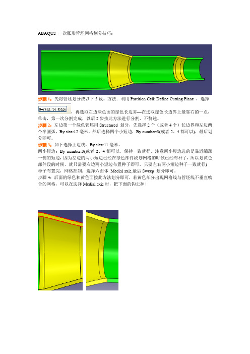
ABAQUS 一次胀形管坯网格划分技巧:步骤1:先将管坯划分成以下5段。
方法:利用Partition Cell: Define Cutting Plane ,选择,再选取左边绿色面的绿色长边界—在选取绿色长边界上最靠右的一点,单击,第一次分割完成,以后2步按此方法进行分割,不赘述。
步骤2:左边第一个绿色管坯用Structured 划分,先选择2个(或者4个)长边界和左边两个半圆弧,By size:12毫米,然后选择四个小短边,By number:3(或者2、4都可以),最后划分即可。
步骤3:如下选择上边线,By size:11毫米。
两小短边:By number:3(或者2、4都可以,保持一致就行,注意两小短边选的是靠近缩颈一侧的短边,因为左边的两小短边已经在绿色部件段划网格的时候已经布种了,所以划黄色部件段的时候,就只需要右边两小短边布置种子即可,只要左右两小短边种子一致就行) 种子布置完,网格控制:选择六面体Medial axis,最后Sweep 划分即可。
步骤4:后面的绿色和黄色面按此方法划分即可,若黄色部分出现网格线与管坯线不垂直吻合的网格,可以在选择Medial axis时,把下面的钩去掉!一次胀形模具网格划分:步骤1:如上图大致划分成五段;步骤2:从最大最规则的地方开始布种划分,这里选择第二个绿色部段,上边两个长边,By size:20毫米,两短边:By number:3,Sweep 划分即可;步骤3:划分右边底部:只需要两小短边划分成2等分即可(根据实际模型长度来看划分成几等分);步骤4:,By size:20毫米,Sweep 划分即可,左边两小短边可布种子为3等分,也可不布置,因为右边已经布置好了,布置左边两小短边对右边有冲突的。
步骤5:,这个和固定模具一样划分即可。
- 1、下载文档前请自行甄别文档内容的完整性,平台不提供额外的编辑、内容补充、找答案等附加服务。
- 2、"仅部分预览"的文档,不可在线预览部分如存在完整性等问题,可反馈申请退款(可完整预览的文档不适用该条件!)。
- 3、如文档侵犯您的权益,请联系客服反馈,我们会尽快为您处理(人工客服工作时间:9:00-18:30)。
Abaqus中三维几何体生成结构网格的分割方法图1 可以直接生成结构网格的三维几何体图2 不可以直接生成结构网格的三维几何体几何体中有孔圆弧≥900 有不能生成二维结构网格的面一个项点有三条以上的边共用图3 分割示例无法生成结构网格的问题分割示例 1 几何体中有孔如将孔分割成半圆或者1/4圆从而去除孔 2 圆弧≥900 如将1800圆弧分成两个900圆弧3 有不能生成二维结构网格的面如半圆周面只含有二个边而一个面至少含有三条以上的边界才能生成二维结构网格所以将半圆分半这样每个面便有三条边 4 一个顶点只能有三条边共用 5 一个区域至少有四个面如四面体6 如果区域中包含拓朴关系则这个区域只能有六个面。
如果多于六个面则如图4所示可以使用virtual topology对面进行合并直至所含的面只有六个面。
图4 使用virtual topology对面进行合并直至所含的面只有六个面7 面与面之间的角度最好接近于90°如果面与面角度≥1500则需进行分割8 对区域中的每个面则有以下要求8.1如果区域不是立方体cube则其面必须是一个整面单一面不能含有多个面片8 8.2 如果区域是立方体cubea side can be a connected set of faces that are on the same geometric surface. In addition the pattern of the faces must allow rows and columns of hexahedral elements to be created in a regular grid pattern along that entire side when the cube is meshed. For example Figure 5shows two acceptable face patterns and the resulting regular grid pattern of elements created by meshing the cubes using the structured meshing technique. Figure 5 Acceptable face patterns and the resulting meshes Figure 6 Unacceptable face patterns. The face pattern shown on the left is unacceptable for structured meshing because each face has only three sides. Each face in the pattern shown on the right has four sides but the pattern does not allow a regular grid of elements to be created on the partitioned side of the cube as shown in Figure 6. Figure 7 A regular grid of elements cannot be created Abaqus中三维几何体生成扫描网格的分割方法无法生成扫描网格的问题分割示例 1 起始面和目标面必须只能是一个整面a single face或是四边形组成的面片组合四边形的面片可以生成规则网格form a regular grid pattern。
图1所示provides two examples of acceptable connecting face patterns 图1 provides two examples of acceptable connecting face patterns 图2 Unacceptable connecting face patterns for swept meshing 2 目标面必须只能是一个整面当中没有独立的边和顶点。
如图3左边所示可以使用扫描网格因为独立的边和点都在起始面上而不在目标面上而右边的则不能生成扫描网格因为目标面上有两个面片。
图4 显示了变截面网格沿着路径生成的扫描网格。
图3 Only the region on the left can be meshed using the sweptmeshing technique 图4 Sweeping the mesh along a varying cross-section 可以使用virtual topology工具将目标面上的面片合并起来从而使其可以使用扫描网格命令。
图5便显示了使用virtual topology工具合并了目标面的面片为一个整面因为零件中含有virtual topology所以它只能使用advancing front algorithm. 图5 Combining faces makes a part swept meshable 3 对于旋转体截面不能与旋转轴有任何相交的点如图6所示。
同样如图7所示截面的一条边与轴线相交但如图8所示mesh the region with hexahedral-dominated elements by generating layers of wedge elements along the axis。
图6 The swept meshing technique cannot mesh a part if an isolated point touches the axis of revolution 图7 Abaqus/CAE cannot mesh a region with hexahedral elements if one or more edges lie along the axis of revolution 图8 Abaqus/CAE can mesh the region with hexahedral-dominated elements 具体实例可见帮助中的17.17.7 Sweep meshing a solid revolved region whose profile touches the axis of revolution 4 在旋转面的截面没有与旋转轴相交如果再满足截面完整则可以生成扫描网格。
图9的截面完整图10的截面丢失图11只有旋转轴上边没有图9 截面完整图10 截面丢失不能生成扫描网格图11 只有旋转轴上边没有可以生成扫描网格旋转区域使用样条曲线生成的截面spline只有在vertices at each end of the spline不在旋转轴上才能生成扫描网格。
5 If a part was created by sweeping a cross-section along a sweep path that is composed of a closed spline the resulting part is meshable only if it is split into two or more regions. 6 想生成扫描网格一般来说对几何体的要求是①起始面含有一个以上的面片且面片间的夹角接近于180°②起始面与目标面的连接面a connecting side必须有4个角cornersThe angle at each of the corners must be close to 90°. ③The angles between the source side and each of the connecting sides should be close to 90°. Similarly the angles between the target side and each of the connecting sides should be close to 90°. 从左到右的第三副图显示了a part with three faces on the source side. When the angle decreases between the faces that form the source side the part no longer satisfies the geometric characteristics of a swept meshable region.最右边的图显示了使用virtual topology将起始面上的面片进行合并后可以扫描网格但质量很差。
17.13.5 Meshing complex solids with hexahedral elements练习An overview of the methods for partitioning cells 定义分割平面使用基准面分割延伸面分割拉伸或扫描面分割Use n-sided patch Sketch planar partition 71. The Virtual Topology toolset What can I do with the Virtual Topology toolset ①Combine faces or edges②Ignore an edge or a vertex③Automatically combine or ignoreentities④Restore entities To preserve mesh quality edges and faces to be combined should have shallow included angles that are close to 180°. The recommended angle is between 120° and 240°. You can use the angle method to choose only adjacent faces with shallow included angles. For more information see “Using the angle method to select multiple objects” Section6.2.3. If the included angle at some edges or vertices lies outside this range Abaqus/CAE displays a warning and allows you to remove those edges or vertices from your selection. If you choose to retain the sharp edges the resulting mesh may not lie on a smooth surface. Figure 71–4 illustrates a mesh on a virtual surface that is not smooth. You can use the controls in the Create Virtual Topology dialog box to automatically ignore unnecessary model details based on a set of geometric parameters. You can control the following parameters to determine which features Abaqus/CAE considers merging with surrounding geometry: Edge length、Face size、Face aspect ratio、Face corner angle、Thickness of faces representing small stair features、Corner angle for combining adjacent edges or faces、Angle and radius controls for combining blends chamfered or rounded corners with surrounding faces、Redundant entities.。
