FemapV11复合材料建模分析
Femap
Femap作者:来源:《CAD/CAM与制造业信息化》2013年第02期出自Siemens PLM Software 的Femap软件是一种先进的工程分析环境。
它不依赖CAD和解算器,已经成为全世界Nastran用户最欢迎的工程分析环境。
它在全世界主要的工程设计组织和顾问中得到广泛应用,可以模拟复杂的产品、系统和过程,其使用领域包括卫星、飞机、国防、汽车、电子产品、重型建筑设备、吊车、海洋船舶和工艺设备。
Femap和NX Nastran已高度整合,能够提供一套综合性的数字化仿真解决方案。
不仅如此,Femap还对所有解算器开放,显示了作为一种核心分析工具的能力和价值。
Femap独立于CAD,除了提供处理非Parasolid几何图形所必需的先进几何工具之外,它还充分利用了SiemensParasolid的软件建模内核,从而可以直接处理Parasolid的表面和实体建模数据。
一、Femap的性能Femap可以帮助工程师和分析师利用FEA建模解决方案以合理的成本轻松、准确地完成最复杂的任务。
基于Windows的用户界面包含以下益处。
(1)在同一个环节中处理多个分析模型,每个模型使用多个视角。
(2)实现从一个模型到另一个模型的“剪切和粘贴”。
(3)使用模型信息树,对建模数据、装配管理、分析设置和结果的处理十分方便。
(4)使用实体编辑器检查和编辑Femap模型数据,在各种Windows应用程序之间复制和粘贴信息。
(5)使用基于栅格的便利表格来显示数据表,很容易对模型和结果进行排序、分组和编辑。
(6)使用可完全自定义的工具栏界面,从界面的最顶层选择Femap实体。
(7)充分利用基于Windows的常用工具的价值,Femap的特色在于它有一整套可完全自定义的停驻式浮动工具栏。
二、可扩展的解决方案1.功能强大而价格低廉的CAEFemap作为独立应用程序包含在Solid Edge软件中,并与NXNastran捆绑,其中的附加模块组成了一系列功能强大、可靠又价格低廉的解决方案,适用于有多种不同的分析要求的公司。
2024版Femap整体介绍

Femap整体介绍•Femap软件概述•Femap界面与操作基础目录•前处理功能详解•求解器原理及性能评估•后处理功能展示与应用•Femap高级功能介绍•总结与展望01 Femap软件概述随着计算机技术的发展,Femap 不断进行升级和改进,逐渐在工程分析领域占据重要地位。
2000年后,Femap加入西门子数字化工业软件家族,成为其重要组成部分,为用户提供更全面的仿真分析解决方案。
起源于20世纪80年代,由美国公司开发,专注于有限元分析(FEA)领域。
软件背景及发展历程提供丰富的CAD 接口,支持多种几何模型导入;具备高效的网格划分工具,可快速生成高质量的有限元模型。
强大的前处理功能内置多种求解器,支持线性、非线性、动力学、热力学等多种分析类型,满足用户不同需求。
全面的求解器支持提供直观的云图、矢量图、动画等多种结果展示方式;支持自定义报告生成,便于用户进行结果分析和交流。
丰富的后处理功能Femap 界面友好,操作简便,支持Windows 操作系统,易于学习和使用。
易用性Femap 核心功能与特点能源领域用于风力发电机、石油管道等设备的强度和疲劳寿命评估。
航空航天用于飞机、发动机等复杂结构的设计和性能分析。
汽车工业应用于车身、底盘、发动机等部件的结构优化和碰撞安全性分析。
电子行业对电子设备结构进行热分析、振动分析等,优化产品设计。
科研与教育为科研机构和高校提供强大的仿真分析工具,促进科研和教学工作的发展。
应用领域与行业分布02 Femap界面与操作基础界面布局及主要功能模块网格划分模块提供多种网格生成技术和网格编辑工具,以满足不同分析需求。
建模模块用于创建和编辑几何模型,支持多种CAD数据格式的导入和导出。
主界面包括菜单栏、工具栏、模型树、属性窗口以及图形窗口等部分,为用户提供了直观的操作环境。
求解模块支持多种求解器接口,可进行线性、非线性、动力学等分析。
后处理模块提供丰富的结果可视化工具,帮助用户直观地理解和评估分析结果。
复合材料结构分析总结
复合材料结构分析总结文章来源:目录1# 复合材料结构分析总结(一)——概述篇5# 复合材料结构分析总结(二)——建模篇10# 复合材料结构分析总结(三)——分析篇13# 复合材料结构分析总结(四)——优化篇做了一年多的复合材料压力容器的分析工作,也积累了一些分析经验,到了总结的时候了,回想起来,总最初采用I-deas,到MSC.Patran、Nastran,到最后选定Ansys为自己的分析工具,确实有一些东西值得和大家分享,与从事复合材料结构分析的朋友门共同探讨。
(一)概述篇复合材料是由一种以上具有不同性质的材料构成,其主要优点是具有优异的材料性能,在工程应用中典型的一种复合材料为纤维增强复合材料,这种材料的特性表现为正交各向异性,对于这种材料的模拟,很多的程序都提供了一些处理方法,在I-Deas、Nastran、Ansys中都有相应的处理方法。
笔者最初是用I-Deas下建立各项异性材料结合三维实体结构单元来模拟(由于研究对象是厚壁容器,不宜采用壳单元),分析结果还是非常好的,而且I-Deas强大的建模功能,但由于课题要求要进行压力容器的优化分析,而且必须要自己写优化程序,I-Deas的二次开发功能开放性不是很强,所以改为MSC.Patran,Patran 提供了一种非常好的二次开发编程语言PCL(以后在MSC的版中专门给大家贴出这部分内容),采用Patran结合Nastran的分析环境,建立了基于正交各项异性和各项异性两种分析模型,但最终发现,在得到的最后结果中,复合材料层之间的应力结果始终不合理,而模型是没有问题的(因为在I-Deas中,相同的模型结果是合理的),于是最后转向Ansys,刚开始接触Ansys,真有相见恨晚的感觉,丰富的单元库,开放的二次开发环境(APDL 语言),下面就重点写Ansys的内容。
在ANSYS程序中,可以通过各项异性单元(Solid 64)来模拟,另外还专门提供了一类层合单元(Layer Elements)来模拟层合结构(Shell 99, Shell 91, Shell 181, Solid 46 和Solid 191)的复合材料。
复合材料的力学模型与性能预测

复合材料的力学模型与性能预测在当今的工程领域,复合材料因其优异的性能而备受关注。
从航空航天到汽车制造,从体育用品到医疗设备,复合材料的应用日益广泛。
然而,要充分发挥复合材料的优势,准确理解其力学行为和预测其性能至关重要。
复合材料是由两种或两种以上具有不同物理和化学性质的材料组合而成的多相材料。
这些不同的组分相互作用,赋予了复合材料独特的性能。
常见的复合材料包括纤维增强复合材料(如碳纤维增强复合材料、玻璃纤维增强复合材料)和颗粒增强复合材料等。
为了研究复合材料的力学行为,科学家们建立了各种各样的力学模型。
其中,微观力学模型着重从材料的微观结构出发,分析单个纤维或颗粒与基体之间的相互作用。
通过这种模型,可以了解复合材料在微观尺度上的应力和应变分布,进而预测其整体性能。
例如,对于纤维增强复合材料,常用的微观力学模型有混合法则和等效夹杂模型。
混合法则基于材料的体积分数和各组分的性能,简单地对复合材料的性能进行估算。
虽然这种方法相对简单,但在一些情况下可能会产生较大的误差。
等效夹杂模型则将纤维视为等效的夹杂体,通过复杂的数学推导来计算复合材料的等效性能,其预测结果通常更为准确。
宏观力学模型则将复合材料视为均匀的连续体,不考虑其微观结构。
这种模型主要用于分析复合材料在宏观尺度上的力学响应,如梁、板等结构的弯曲、拉伸和压缩等行为。
常见的宏观力学模型包括经典层合板理论和有限元方法。
经典层合板理论将复合材料层合板视为由多层不同方向的单层板组成,通过叠加各单层板的贡献来计算层合板的整体性能。
这一理论在工程中得到了广泛的应用,但它对于复杂的加载情况和边界条件的处理能力有限。
有限元方法则是一种更为强大的工具,它可以模拟各种复杂的几何形状、加载条件和边界约束。
通过将复合材料结构离散为有限个单元,并对每个单元的力学行为进行分析,最终得到整个结构的响应。
有限元方法在复合材料的设计和分析中发挥着重要的作用,但它需要较高的计算资源和专业的软件支持。
复合材料模型建模与分析
复合材料模型建模与分析1.Cohesive单元建模方法1.1 几何模型使用内聚力模型(cohesive zone)模拟裂纹的产生和扩展,需要在预计产生裂纹的区域加入cohesive层。
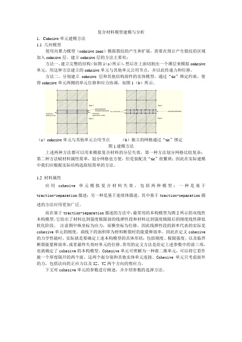
建立cohesive层的方法主要有:方法一、建立完整的结构(如图1(a)所示),然后在上面切割出一个薄层来模拟cohesive 单元,用这种方法建立的cohesive单元与其他单元公用节点,并以此传递力和位移。
方法二、分别建立cohesive层和其他结构部件的实体模型,通过“tie”绑定约束,使得cohesive单元两侧的单元位移和应力协调,如图1(b)所示。
(a)cohesive单元与其他单元公用节点(b)独立的网格通过“tie”绑定图1.建模方法上述两种方法都可以用来模拟复合材料的分层失效,第一种方法划分网格比较复杂;第二种方法赋材料属性简单,划分网格也方便,但是装配及“tie”很繁琐;因此在实际建模中我们应根据实际结构选取较简单的方法。
1.2 材料属性应用cohesive单元模拟复合材料失效,包括两种模型:一种是基于traction-separation描述;另一种是基于连续体描述。
其中基于traction-separation描述的方法应用更加广泛。
而在基于traction-separation描述的方法中,最常用的本构模型为图2所示的双线性本构模型。
它给出了材料达到强度极限前的线弹性段和材料达到强度极限后的刚度线性降低软化阶段。
注意图中纵坐标为应力,而横坐标为位移,因此线弹性段的斜率代表的实际是cohesive单元的刚度。
曲线下的面积即为材料断裂时的能量释放率。
因此在定义cohesive 的力学性能时,实际就是要确定上述本构模型的具体形状:包括刚度、极限强度、以及临界断裂能量释放率,或者最终失效时单元的位移。
常用的定义方法是给定上述参数中的前三项,也就确定了cohesive的本构模型。
Cohesive单元可理解为一种准二维单元,可以将它看作被一个厚度隔开的两个面,这两个面分别和其他实体单元连接。
西门子发布最新版Femap软件显著提高仿真效率

西门子发布最新版Femap软件显著提高仿真效率
佚名
【期刊名称】《工业设计》
【年(卷),期】2013(000)001
【摘要】最新发布的西门子Femap^TM软件显著增强了数据处理和图形性能,进而提高产品开发过程中仿真和分析的效率。
11版(Femap11)的数据访问速度提高了25倍,内存使用率减少了80%,因而能够交付一个更小的、更易处理的模型文件。
此外,与之前的版本相比,
【总页数】1页(P10-10)
【正文语种】中文
【相关文献】
1.西门子公司发布新一代高性能PLC控制器与最新版TIA博途V12软件平台
2.软件升级西门子SIMATIC水处理软件库最新版本发布
3.西门子发布新一代PLC控制器与最新版TIA博途V12软件平台
4.西门子发布最新版NX软件为实现数字化车间进一步提供扩展的工具箱
5.西门子新一代高性能PLC控制器与最新版TIA博途V12软件平台隆重发布
因版权原因,仅展示原文概要,查看原文内容请购买。
Femap 介绍
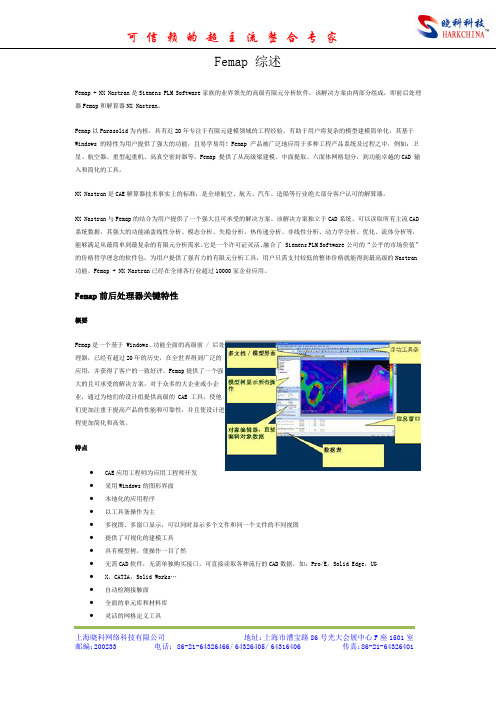
Femap 综述Femap + NX Nastran是Siemens PLM Software家族的业界领先的高级有限元分析软件。
该解决方案由两部分组成,即前后处理器Femap和解算器NX Nastran。
Femap以Parasolid为内核,具有近20年专注于有限元建模领域的工程经验,有助于用户将复杂的模型建模简单化,其基于Windows 的特性为用户提供了强大的功能,且易学易用!Femap 产品被广泛地应用于多种工程产品系统及过程之中,例如:卫星、航空器、重型起重机、高真空密封器等。
Femap 提供了从高级梁建模、中面提取、六面体网格划分,到功能卓越的CAD 输入和简化的工具。
NX Nastran是CAE解算器技术事实上的标准,是全球航空、航天、汽车、造船等行业绝大部分客户认可的解算器。
NX Nastran与Femap的结合为用户提供了一个强大且可承受的解决方案。
该解决方案独立于CAD系统,可以读取所有主流CAD 系统数据,其强大的功能涵盖线性分析、模态分析、失稳分析、热传递分析、非线性分析、动力学分析、优化、流体分析等,能够满足从最简单到最复杂的有限元分析需求。
它是一个许可证灵活、融合了 Siemens PLM Software公司的“公平的市场价值”的价格哲学理念的软件包,为用户提供了强有力的有限元分析工具,用户只需支付较低的整体价格就能得到最高级的Nastran 功能。
Femap + NX Nastran已经在全球各行业超过10000家企业应用。
Femap前后处理器关键特性概要Femap是一个基于 Windows、功能全面的高级前 / 后处理器,已经有超过20年的历史,在全世界得到广泛的应用,并获得了客户的一致好评。
Femap提供了一个强大的且可承受的解决方案,对于众多的大企业或小企业,通过为他们的设计组提供高级的 CAE 工具,使他们更加注重于提高产品的性能和可靠性,并且使设计进程更加简化和高效。
2024版FEMAP培训教程1

03
网格划分与优化策略
网格划分原则及技巧分享
遵循几何特征
根据模型的几何形状、尺寸和特 征进行网格划分,确保网格能够
准确反映模型的细节。
均匀性原则
尽量保持网格的均匀性,避免出 现过大或过小的网格,以提高计 算精度和稳定性。
问题解答和互动交流环节
针对学员在练习过程 中遇到的问题,进行 解答和指导。
通过讨论和互动,加 深对有限元分析方法 和应用的理解。
鼓励学员之间的互动 交流,分享各自的经 验和心得。
THANKS
感谢观看
FEMAP培训教程1
目录
• FEMAP软件简介与安装 • 模型建立基础 • 网格划分与优化策略 • 求解器设置与运算过程监控 • 后处理功能深入挖掘 • 实际应用案例分析与讨论
01
FEMAP软件简介与安装
FEMAP软件概述
FEMAP是一款广泛应用于有限元分析的软件,具有强大的前处理和后处理功能。
支持多种CAD软件格式(如 SolidWorks、CATIA、AutoCAD等) 的导入,实现与外部CAD软件的无缝 对接。
材料属性设置与分配
01
02
03
材料库管理
内置丰富的材料库,用户 可自定义材料属性并添加 到材料库中,方便后续调 用。
材料属性分配
将材料属性分配给几何模 型中的各个部分,确保分 析结果的准确性。
进度条
部分软件提供进度条果文件类型
01
了解并掌握各种结果文件的输出方式和查看方法,如文本文件、
二进制文件等。
后处理软件
02
利用后处理软件查看和分析结果文件,如云图、等值线图等。
复合材料热处理数值模拟模型建立及参数优化

复合材料热处理数值模拟模型建立及参数优化引言:复合材料是一种由两种或两种以上不同材料组成的新材料,具有较高的强度、刚度和耐磨性,被广泛应用于航空航天、汽车、船舶等领域。
在复合材料的制造过程中,热处理是一种重要的工艺,可以显著改善复合材料的性能。
数值模拟是研究复合材料热处理过程的有效方法,可以帮助工程师优化工艺参数,提高产品质量。
本文将探讨建立复合材料热处理数值模拟模型及参数优化的方法。
一、复合材料热处理数值模拟模型建立1.材料建模复合材料分为纤维增强复合材料和粒子增强复合材料两种。
在建立数值模拟模型时,需要将复合材料的宏观性能转化为材料模型中的本构关系。
对于纤维增强复合材料,可以通过等效材料法将其转化为各向同性材料进行建模;对于粒子增强复合材料,可以考虑粒子间的相互作用力,采用微观力学模型进行建模。
2.热传导模型热传导是复合材料热处理过程中的重要现象,其数值模拟模型需要考虑复合材料的热导率、热扩散系数和热源等因素。
可以利用有限元方法建立复合材料的热传导模型,并根据实际情况引入适当的边界条件。
3.相变模型复合材料在热处理过程中可能会发生相变,如固态相变、液态相变等。
相变模型的建立需要考虑复合材料的相变温度、相变潜热等参数,可以采用相场方法或相变耦合模型进行建模。
4.热应力模型由于复合材料的热膨胀系数和热导率在不同温度范围内可能存在差异,热处理过程中可能引起热应力的产生。
建立复合材料的热应力模型可以帮助预测热处理过程中的应力分布,进一步优化热处理参数。
二、参数优化方法1.设计实验为了建立准确可靠的数值模拟模型,在进行参数优化之前,需要进行一系列实验来获取材料的热性能参数和相关数据。
实验内容包括材料的热导率、热膨胀系数、热容等参数的测量,以及热处理过程中温度场、应力场等数据的采集。
2.响应面法响应面法是一种常用的参数优化方法,通过建立数值模拟模型,选取关键参数并进行多组实验,然后利用响应面模型对实验结果进行分析和拟合,最终得到最优参数组合。
基于FEM的水泥基压电复合材料的性能分析

元进行分析 ,能够得到复合材料 内部 的应力 、应变
分布和 电压 、电位移分布 。对复合材料的实 际应用 提供实验所无法给 予的指导和帮助 。 本 文对 水泥基 压 电复合材 料 建立 了有 限元模
型。 分析 了水泥基压 电复合材料 的压 电性能,得 出 了材 料 内部 的位 移和 应变 分布 以及压 电应变 常数
基 于 F M 的水 泥 基压 电复合 材料 的性 能分析 E
张宗振 ,徐 东字,鞠 超 ,黄世峰 ,程 新
( 济南大学 材料科 学与工程 学院,山东 济南 2 02 ) 5 0 2
摘 要 :建 立 了 13型水 泥 基 压 电复合 材 料 的 有 限元 模 型 , 并对 其 进 行 了静 力 分 析 、模 态 分 析 和 瞬态 动 力 学分 - 析 。得 到 了水 泥 基 压 电复合 材 料 的 内部应 力 应 变 分 布 、水 泥 基 体对 复合 材 料 压 电 性 能 的影 响 、 复合 材 料 的 厚度 振 动 模态 和 在 动 态 载荷 下 的响 应 情况 。发 现 水 泥 基压 电复 合 材 料产 生 的驱 动 应变 和 节 点 应 力 都集 中在 压 电 陶瓷 柱 上 , 高 泊松 比和 低 弹性 模 量 的 水泥 基 体 能 够 增 加 复合 材 料 的 压 电性 能 ;低 频下 水 泥 基 压 电复合 材 料 的振 动 特 性 与 压 电 陶瓷 相 同 ,且 对 外 部 的动 态 激 励 有着 良好 的 线性 响应 。 关 键 词 :智 能 材 料 ;水 泥 基 压 电 复合 材 料 ; 有 限元 模 型
根 据压 电方 程压 电陶瓷 的本构 关系矩 阵可 以
基金 项 目: 国 家 自然 科 学 基 金 资助 项 目 (0 4 0 2 5922) 新 (9 3) 16 一
复合材料构件数字化建模技术研究

复合材料构件数字化建模技术研究第一篇:复合材料构件数字化建模技术研究复合材料是一种由高强度、高刚度增强材料铺设在基体中所构成的新型材料,具有高比强度、高比模量、良好的抗疲劳性和抗腐蚀性等一系列优点。
随着复合材料在飞机上用量的日益增加,其重要性也越来越突出。
由于先进复合材料的可设计性及其在提高飞机性能上的巨大潜力,复合材料在飞机上应用的部位和用量的多少几乎已成为衡量当代飞机先进性的一个重要标志。
然而复合材料的结构设计与传统金属结构的设计又有许多本质的区别且更加复杂。
原因是复合材料在结构设计时并无确定的结构材料存在,其产品和材料的研制是同时进行的,材料的制造同样要按结构设计进行,因此需要设计人员与分析、制造人员之间更密切地配合,数据传递也更为频繁。
复合材料传统研制方法在传统的复合材料研制模式中,设计、分析及制造之间的数据是通过模拟量传递的。
设计工程师根据设计输入条件,依靠自身的经验和空间想象能力绘制铺层图和铺层顺序表,其中包括铺层的每一个细节,如尺寸、形状、剪口、铺层顺序、铺层角度等;强度校核时,分析工程师根据图纸内容及其对图纸的理解,将铺层信息等内容反映到强度计算模型中;工厂制造时,工装设计人员根据图纸设计模线样板及模具,零件制造车间再根据模线样板下料、铺叠(。
成型工艺以手工为主,构件质量在很大程度上依赖于工人的经验和熟练程度。
总的来说,这种传统的复合材料设计制造方式极可能会在设计、分析、制造(CAD/CAE/CAM)间出现数据源不唯一的情况,且制造的效率和精度都比较低,成本也过高,极大阻碍了复合材料的广泛应用。
复合材料数字化设计、分析与制造复合材料设计、制造专用软件的开发以及各种复合材料数控制造设备(如预浸料自动剪裁设备、激光投影设备和纤维自动铺放设备等)的研制成功,使复合材料构件研制过程的数据以数字量传递成为可能,设计、分析、制造结合得更为紧密。
设计、分析与制造见的数据传递通过在复合材料构件研制过程中引入数字化技术,可以保证设计、分析、制造数据源的唯一,真正做到复合材料CAD/CAE/CAM一体化,便于数字量传递,减少研制时间,加快研制进度。
Femap图文教程

常用工具栏功能介绍
缩放、旋转和平移视图
撤销和重做
用于调整模型视图的显示方式。
选择和取消选择
撤销上一步操作或重做已撤销的 操作。
选择或取消选择模型中的元素。
新建、打开和保存文件
用于创建新文件、打开已有文件 和保存文件。
属性窗口
显示所选元素的属性信息,如几 何尺寸、材料属性等。
模型视图操作技巧
使用鼠标中键进行旋转和缩放视图。
05
在非关键区域采用较粗的网格划分,以提高计算效率。
06
注意网格的连续性和协调性,避免出现畸形网格或重叠网格。
04
Femap建模与网格划分
几何建模方法
01
02
03
直接建模
在Femap中直接创建几何 模型,利用基本图形元素 (如点、线、面)构建复 杂结构。
导入外部模型
支持多种CAD格式导入, 如STEP、IGES、 Parasolid等,实现与其他 CAD系统的无缝集成。
易用。
02
Femap界面与基本操作
界面组成与布局
菜单栏
包含文件、编辑、视图、工具、 窗口和帮助等菜单项,用于执 行各种命令。
状态栏
显示当前操作状态和相关提示 信息。
主窗口
显示模型、分析结果和其他主 要信息。
工具栏
提供常用命令的快捷按钮,方 便用户快速执行操作。
模型树
展示模型的层次结构,方便用 户管理和查看模型。
非
何在Femap中定义相关
线
材料参数。
性
介绍接触问题的基本原
理和求解方法,包括接
案 例
触对的定义、接触刚度
解
的设置等,并展示
析
Femap中的相关操作。
复合材料模型

复合材料模型复合材料是由两种或两种以上的材料组合而成的新型材料,它具有优良的综合性能,广泛应用于航空航天、汽车、建筑等领域。
复合材料的力学性能对其工程应用具有重要影响,因此建立合理的复合材料模型对于预测和优化材料性能至关重要。
首先,复合材料的模型可以从微观层面和宏观层面进行建立。
在微观层面,可以采用有限元分析等方法,考虑单根纤维或复合材料中的微观结构,通过数学模型描述纤维与基体之间的相互作用,预测复合材料的强度、刚度等力学性能。
在宏观层面,可以采用连续介质力学模型,将复合材料视为均质、各向同性或各向异性的连续介质,通过弹性力学、塑性力学等理论建立复合材料的宏观力学模型。
其次,复合材料的模型可以根据不同的应用和要求进行选择。
例如,对于复合材料的强度分析,可以采用断裂力学模型,考虑裂纹的扩展行为,预测复合材料的断裂韧性和疲劳寿命;对于复合材料的成型和加工,可以采用流变学模型,考虑材料的流变行为,优化成型工艺参数,提高复合材料的成型质量。
此外,复合材料的模型还可以结合实验数据进行验证和修正。
通过对复合材料的拉伸、压缩、弯曲等力学性能进行实验测试,获取材料的应力-应变曲线和损伤演化规律,将实验数据与模型预测结果进行比较,验证模型的准确性,并对模型参数进行修正,使其更符合实际材料的力学行为。
综上所述,复合材料模型的建立是复合材料研究的基础,它对于预测和优化复合材料的力学性能具有重要意义。
通过建立合理的复合材料模型,可以为复合材料的设计、制备和工程应用提供理论指导和技术支持,推动复合材料在各领域的广泛应用和发展。
因此,在复合材料研究中,需要不断深化对复合材料模型的理论研究和实验验证,不断提高模型的准确性和适用性,为复合材料的发展做出更大的贡献。
DEFORM3DV11介绍

DEFORM3DV11介绍DEFORM 3D V11介绍1 DEFORM概览DEFORM是一款基于有限元法(FEM)的模拟分析软件。
其在金属材料成形及其相关领域被用来分析各种材料的成形过程以及热处理过程。
通过在计算机上模拟材料的制造成型过程,这款软件可以在以下方面帮助到工艺设计师和工程师:减少进行昂贵的车间试验以及重新设计工具和流程的需求改善工具和模具的设计来降低生产成本及材料浪费缩短将新产品推向市场的时间改善产品的微观结构及强度提升工艺控制质量不同于别的通用的有限元软件,DEFORM只为成型设计。
DEFORM的友好型界面可以让工程师们更好地专注于成型的工艺设计而不是繁琐的软件学习上。
DEFORM一个很大的亮点就在于它能够自动地重画网格来优化网格质量。
DEFORM -HT能够很好地模拟热处理过程,包括回火,退火,淬火,正火以及渗碳。
DEFORM-HT可以预测硬度,残余应力,淬火变形以及其他与热处理相关的机械性能和材料性能。
DEFORM同样具备其他先进的功能,如预测塑性断裂,微观组织演化,切削加工变形和切屑形态。
可扩展的用户子程序使高级研究人员可以自定义他们自己的本构、断裂和微观结构模型以及压力机规格和非金属材料。
Multiple Operation(MO)界面允许用户建立连续的模拟过程,其可自动按顺序完成模拟不用用户挨个操作。
DEFORM具有用于特定过程的不同向导,例如形状轧制,环锭轧制,挤压,逆向热处理,机加工,嵌齿,热处理,热处理炉等,这些向导是自定义的,可帮助用户轻松设置复杂的过程。
DOE(Design of Experiment)帮助用户研究指定范围内各种参数对过程的影响。
OPTIMIZA TION可帮助用户优化特定参数,例如模具负载,最大值。
钢坯应变,损伤值等最后,DEFORM能够研究从铸锭转换到成型,加工和热处理,再到最终产品安装的整个制造链。
同时,现代的用户界面设计使生产工程师和研究科学家均可轻松应用2 利用DEFORM分析的流程设计工艺过程可以从变形前变形后工件的形状,材料,变形温度等方面考虑采用哪种工具收集所需数据最主要的就是材料数据,如材料的应力应变方程,材料的属性值等处理条件数据在前处理界面设置好模拟过程提交模拟使用后处理查看结果假如结果不对。
工业复合材料零部件仿真热变形建模方法

工业复合材料零部件仿真热变形建模方法在工业复合材料的世界里,热变形这件事儿可是个大问题,尤其是在做零部件仿真时。
你要知道,工业复合材料那可不是一般的材料,它们的结构复杂,性能优异,但也容易受热膨胀或变形。
咱们做仿真分析,目的就是要预测这些零部件在不同工况下会怎么样,尤其是高温下,它们会变形到什么程度,真心让人头大。
说到热变形,简单来说,就是材料在受热后,形状发生了变化。
就像你拿个塑料杯子放到热水里,杯子会软,甚至变形,这就是热变形的简单表现。
工业复合材料零部件也是一样,它们在工作环境中承受各种热负荷,有时候是由于外界温度的变化,有时候是内部的温度波动。
材料在温度的作用下,可能会出现翘曲、膨胀,甚至是开裂。
这可不是什么小问题,尤其是当这些零部件一旦变形,就可能影响整个机械系统的性能,严重的甚至导致系统失效。
想象一下,一台发动机里的关键部件因为热变形卡住了,结果导致整个系统报废,真的是让人“头顶冒火”。
所以说,怎么通过仿真技术准确预测这些变化,成了我们亟待解决的难题。
通过仿真分析,我们可以在设计阶段就预测出热变形的情况,这样一来,设计师就能根据预测结果对材料的选择、部件的形状、加工工艺进行调整,避免一些“后悔药”根本没法救的情况。
这个过程可不是说做做计算就能完事儿的,而是需要大量的试算和模拟,得根据不同材料的特性、温度变化、外部环境等因素,结合实际生产中的情况,进行多维度的分析。
要说仿真建模的难点,最关键的一个问题就是材料的热膨胀系数。
你要明白,不同材料的膨胀系数差异大得很。
有些材料,温度稍微一高,它就开始膨胀;而有些材料,哪怕加热得再高,它也没啥大变化。
像金属、塑料、碳纤维这些复合材料,它们的膨胀系数各不相同。
如果咱们不能精确地了解这些材料的热响应,仿真出来的结果肯定不准确,最后的设计也会偏离实际需求。
就好比你买鞋子,不知道自己脚的具体尺寸,结果鞋子买大了,穿起来就不舒服;买小了,根本穿不上。
复合材料的热变形往往不简单地表现为均匀的膨胀或收缩。
2024年度《FEMAP示例入门与提高》版本83

根据桥梁的实际支撑情况,设置桥墩底部 的固定约束、桥面的滑动约束等。
通过FEMAP进行桥梁结构的有限元分析, 得到桥梁的应力、变形等结果,并评估其 安全性。
2024/3/23
20
05
求解器选择与结果输 出设置
2024/3/23
21
求解器类型介绍及选择建议
直接求解器
基于直接法,适用于中小规模问题,计算精度高,但内存消耗较大 。
的车身变形、加速度、能量吸收等数据。
02
可视化设计
根据数据的类型和特点,选择合适的图表类型和色彩方案,设计出直观
、易懂的可视化界面。
2024/3/23
03
结果展示
将设计好的可视化界面应用于汽车碰撞安全性分析结果,通过图表、动
画等形式展示车身在不同碰撞工况下的表现,帮助用户更直观地了解汽
车的安全性能。
飞机机翼结构优化设计结果
展示飞机机翼结构优化设计的结果,包括优化前后的性能对比、成 本降低和效益提升等方面的分析。
32
THANKS
感谢观看
2024/3/23
33
迭代求解器
基于迭代法,适用于大规模问题,内存消耗较小,但计算精度可能 受迭代次数和收敛准则影响。
选择建议
对于中小规模、对精度要求高的问题,推荐使用直接求解器;对于大 规模问题或需要快速求解的场景,推荐使用迭代求解器。
2024/3/23
22
结果输出设置方法
结果文件类型
支持多种格式的结果文件输出,如文本文件、 Excel文件、图形文件等。
2024/3/23
施加边界条件
根据实际问题,为模型施加适当的边界条 件,如固定约束、位移约束、力或压力载 荷等。
FemapV11复合材料建模分析

FemapV11复合材料建模分析IntroductionIn this exercise, you perform a linear stress analysis of a composite laminate fitting. The steps you will perform in this workshop are:Import a Femap Neutral File with geometry edits for meshing already appliedCreate two layups for the fitting –one for the normal thickness of the fitting and a second for reinforced areas around themounting holesCreate properties for the two layupsMesh the fittingAssign material directions to the meshApply constraints and loads to the fittingAnalyze the fitting and review resultsStep 1:Start Femap and Import Parasolid Geometry of the FittingStart FemapFrom either a desktop icon, or from the Windows Start menu, select the icon for Femap v11.Set your Femap preferences for the correct Geometry Scale Factor.The Geometry Scale Factor is number of length units permeter used by Parasolid.Select the command, File > Preferences.In the Preferences dialog box, select the Geometry/Model tab.Under the Geometry Preferences option group, set theGeometry Scale Factor to Millimeters.Click OK to apply the changes and close the dialog box.Import a Femap Neutral file with the fitting geometry editing for meshing and with mesh sizing already applied.Select the command, File, Import, Femap Neutral.In your workshop folder, select the Parasolid file,Fitting.NEU.In the Neutral File Read Options dialog box, click OK to read in the fitting.Your Femap model should appear as below.In this model, the green surfaces represent 5 mm offsets from the holes modeled as washers and the orange surfaces represent pads around the holes. These areas will be meshed with a thicker laminate than the rest of the fitting. Mesh sizes have also been preset for this model, with a default mesh size of 5.There are also three (3) additional coordinate systems that will be used to set material orientations. Display of points, coordinate systems and nodes are turned off in the current view.Save the model.Click the Save Model icon on the Model toolbar to execute the File > Save command.In the File, Save As dialog box, navigate up one folder to select the Exercises folder.Enter laminate-fitting as the name of the Femap model file.The .modfem extension for Femap models will beautomatically appended to the name.Click Save to complete saving the Femap model file.Step 2:Create two layups for the fitting – one for thenormal thickness of the fitting and a second forreinforced areas around the cutout and themounting holesSave your Femap model.Create a new 2D orthotropic material using a prepeg fabric.Using the Model Info pane, right-click on the Material object and select new.In the Create Material dialog box, click the Type button and select Orthotropic (2D) in the Material Type dialog box.Click OK to confirm your selection.You will now select a fabric from a material library provided with this workshop.Click the Load button in the Define Material dialog box.In the Select From Library dialog box, click the Choose Library button.In the Library File dialog box, navigate to your workshop folder and select the libraryComposites_Material_Library.esp, then, click the Openbutton to load the library into your model.Select the material, CFS003 Carbon LMT25 Epoxy Fabric in the Select From Library dialog box, then, click OK to load the attributes of this material into the Define Material dialog box.Note that the tensile and compressive properties are very similar for this composite fabric material.Click OK to complete creating the material.Since this will be the only material used in this model, you should Cancel the command.Note: If you want to load all the materials in a library into a Femap model, use the command, File, Import,Femap N eutral and select the material library. You’llneed to change the file extension to from .neuto .esp.Create a layup for the standard thickness of the fitting.Right-click on the Layups object in the Model Info pane and select New.In the Layup Editor dialog box, create Global Plies that represent the top, bottom and mid-plane of the layups byclicking the Global Ply iconIn the Global Ply Definition dialog box, click the New button.In the New Global Ply dialog box, set the Title to Bottom Global Ply.Select the material you just loaded from the material library and set the Thickness to .25.Click the More button to continue creating two moreglobal plies.Set the next Title to Midplane Global Ply.Select the material you just loaded from the material library and set the Thickness to .25.Click the More button to continue creating the final global ply.Set the next Title to Top Global Ply.Select the material you just loaded from the material library and set the Thickness to .25.Click the OK button to complete creating global plies.You should now see three global plies.In the Global Ply Definition dialog box, click Done.In the Layup Editor dialog box, set the Title to Standard Layup.Select the Global Ply ID, 1..Bottom Global Ply.Select the Material, 1..CFS003 Carbon LMT25 Epoxy Fabric.Set the Thickness to .25 and the Angle to 0.Click the New Ply button.For the next ply, set the Global Ply ID to 0..None.Set the Angle to 45.Click the New Ply button.Continue creating another ply by setting the Angle to 0.Note how the previous selections for Global Ply ID, Material,Thickness and Angle maintained.Click the New Ply button.Duplicate plies 2 and 3.Select Ply 2 in the Layup Editor dialog box.While holding the Shift key, select Ply 3.Click the Duplicate button.Note how the two plies have been copied at the top of the layup. Also note how the value of the Total Thickness hasbeen updated.Click OK to create the layup and to exit the Layup Editor dialog box.Click Cancel to end creating layups.In this step, you will display the Laminate Equivalent Properties using the Entity Info pane.Open the Entity Info pane by either clicking the Entity Info icon on the Panes toolbar, or by selecting the command, Tools, Entity Info.Edit the layup.Right-click on the Standard Layup object in the Model Info pane and select Edit from the menu.Note how the Laminate Equivalent Properties are nowdisplayed in the Entity Info pane including:Total ThicknessIn-Plane PropertiesBending/Flexural PropertiesA, B, D, A-Inverse, B-Inverse and D-Inverse matricesIn the Layup Editor dialog box, using the Shift key, select plies 4 and 5, and click the Duplicate button.Again, note how the Entity Info window’s display of theLaminate Equivalent Properties have been updated.Since we want a symmetric layup, using the Shift key, select plies 2 through 6, then click the Symmetric button.Note that you now have a total of 12 plies and a totalthickness equal to 3.Select Ply 12.Note that until only a single ply is selected, the New Plybutton is inactive. However, you will need to deselect the ply in order to create a new ply on top of the layup;otherwise the new ply will be created below the selected ply.While holding the Ctrl key, select Ply 12.Set the Global Ply ID to 3..Top Global Ply. Set the Angle to0 and then, click the New Ply button.Update the Global Ply for the middle plies.Select Ply 7.Set the Global Ply ID to 2..Midplane Global Ply.Click OK to complete the creation of the layup. Save your Femap model.Copy the first layup.Right-click on the newly created layup in the Model Info pane and select Copy from the menu.Modify the copied layup to represent the reinforced areas around the holes.Right-click the copied layup in the Model Info pane and select Edit from the menu.In the Layup Editor dialog box, change the Title to Hole Reinforcement Layup.While the Ctrl key, select plies 5, 6, 8 and 9.Click the Duplicate button.Note that the duplicated plies are now at the top of the layup.。
Femap_v11安装说明
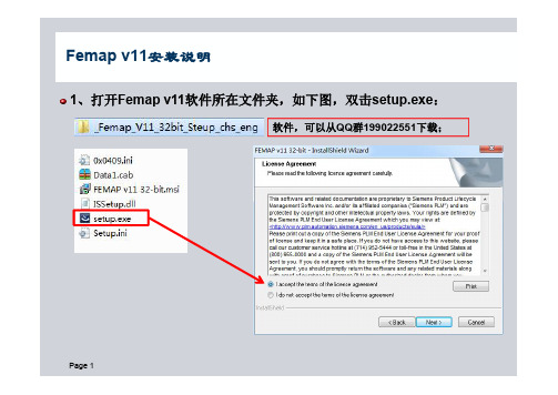
1、打开Femap v11软件所在文件夹,如下图,双击setup.exe :Femap v11安装说明软件,可以从QQ 群199022551下载;2、修改Femap v11软件安装路径,如下图:Femap v11安装说明3、选择Femap v11软件模块,如下图:Femap v11安装说明安装Femap 和求解器NX Nastran ;;实例文件;帮助文件;建议此四项为必选项;安装热流分析求解器IDEAS TMG ;动态分析后处理工具包;Solid Edge 连接;此三项为可选项;4、选择Femap v11语言,如下图:Femap v11安装说明、中文和德文;;;Femap 安装程序提供3种语言选项:英文、中文和德文;建议选择中文;安装后可以非常方便进行中文-英文相互调换;5、选择Femap v11的License 类型,如下图:Femap v11安装说明:单机版、网络版和;;安装后可以非常、网络版和;Femap 安装程序提供3种许可文件类型选项:单机版、网络版和300节点演示版;建议选择网络版;安装后可以非常方便进行单机版、网络版和300节点演示版相互调换;6、安装Femap v11程序,如下图:Femap v11安装说明在安装的最后需要创建一个scratch 文件夹,以存放分析时求解器Nastran 生成的临时文件;如果没有这个目录,则不会进行任何分析;其路径可以根据需要修改;Femap 安装非常方便,一般只需要10分钟左右即可安装完成;根据你电脑硬件配置不同,及选择模块不同,安装时间可能有所差别;7、Femap v11中文版,及中英文版转换方法,如下图:Femap v11安装说明Femap 中文版对于初学者来说,界面非常友好,方便使用者很快上手;但是在分析时,有时分析结果在消息栏中会出现乱码,不方便判断结果;方法:关闭,在,将其剪切到其,重新启动再,就不会出现乱码;,就把上面的文。
,界,方便使用者很快上手但是在分析时,有时分析结果在,不方便判断;这样就需要把中文版转换为英文版,方法:关闭Femap 软件,在Femap 安装目录下找到feres1100.dll 文件,将其剪切到其它文件夹中,重新启动Femap ,再次计算,就不会出现乱码;如果需要中文版时,就把上面的文件再复制回来即可。
- 1、下载文档前请自行甄别文档内容的完整性,平台不提供额外的编辑、内容补充、找答案等附加服务。
- 2、"仅部分预览"的文档,不可在线预览部分如存在完整性等问题,可反馈申请退款(可完整预览的文档不适用该条件!)。
- 3、如文档侵犯您的权益,请联系客服反馈,我们会尽快为您处理(人工客服工作时间:9:00-18:30)。
IntroductionIn this exercise, you perform a linear stress analysis of a composite laminate fitting. The steps you will perform in this workshop are:∙Import a Femap Neutral File with geometry edits for meshing already applied∙Create two layups for the fitting – one for the normal thickness of the fitting and a second for reinforced areas around themounting holes∙Create properties for the two layups∙Mesh the fitting∙Assign material directions to the mesh∙Apply constraints and loads to the fitting∙Analyze the fitting and review resultsStep 1:Start Femap and Import Parasolid Geometry of the FittingStart Femap∙From either a desktop icon, or from the Windows Start menu, select the icon for Femap v11.Set your Femap preferences for the correct Geometry Scale Factor.The Geometry Scale Factor is number of length units permeter used by Parasolid.∙Select the command, File > Preferences.∙In the Preferences dialog box, select the Geometry/Model tab.∙Under the Geometry Preferences option group, set the Geometry Scale Factor to Millimeters.∙Click OK to apply the changes and close the dialog box.Import a Femap Neutral file with the fitting geometry editing for meshing and with mesh sizing already applied.∙Select the command, File, Import, Femap Neutral.∙In your workshop folder, select the Parasolid file,Fitting.NEU.∙In the Neutral File Read Options dialog box, click OK to read in the fitting.Your Femap model should appear as below.In this model, the green surfaces represent 5 mm offsets from the holes modeled as washers and the orange surfaces represent pads around the holes. These areas will be meshed with a thicker laminate than the rest of the fitting. Mesh sizes have also been preset for this model, with a default mesh size of 5.There are also three (3) additional coordinate systems that will be used to set material orientations. Display of points, coordinate systems and nodes are turned off in the current view.Save the model.∙Click the Save Model icon on the Model toolbar to execute the File > Save command.∙In the File, Save As dialog box, navigate up one folder to select the Exercises folder.∙Enter laminate-fitting as the name of the Femap model file.The .modfem extension for Femap models will beautomatically appended to the name.∙Click Save to complete saving the Femap model file.Step 2:Create two layups for the fitting – one for thenormal thickness of the fitting and a second forreinforced areas around the cutout and themounting holesSave your Femap model.Create a new 2D orthotropic material using a prepeg fabric.∙Using the Model Info pane, right-click on the Material object and select new.∙In the Create Material dialog box, click the Type button and select Orthotropic (2D) in the Material Type dialog box.Click OK to confirm your selection.You will now select a fabric from a material library provided with this workshop.∙Click the Load button in the Define Material dialog box.∙In the Select From Library dialog box, click the Choose Library button.∙In the Library File dialog box, navigate to your workshop folder and select the libraryComposites_Material_Library.esp, then, click the Openbutton to load the library into your model.∙Select the material, CFS003 Carbon LMT25 Epoxy Fabric in the Select From Library dialog box, then, click OK to load the attributes of this material into the Define Material dialog box.Note that the tensile and compressive properties are very similar for this composite fabric material.∙Click OK to complete creating the material.∙Since this will be the only material used in this model, you should Cancel the command.Note: If you want to load all the materials in a library into a Femap model, use the command, File, Import,Femap Neutral and select the material library. You’llneed to change the file extension to from .neuto .esp.Create a layup for the standard thickness of the fitting.∙Right-click on the Layups object in the Model Info pane and select New.∙In the Layup Editor dialog box, create Global Plies that represent the top, bottom and mid-plane of the layups byclicking the Global Ply icon∙In the Global Ply Definition dialog box, click the New button.∙In the New Global Ply dialog box, set the Title to Bottom Global Ply.Select the material you just loaded from the material library and set the Thickness to .25.Click the More button to continue creating two moreglobal plies.∙Set the next Title to Midplane Global Ply.Select the material you just loaded from the material library and set the Thickness to .25.Click the More button to continue creating the final global ply.∙Set the next Title to Top Global Ply.Select the material you just loaded from the material library and set the Thickness to .25.Click the OK button to complete creating global plies.You should now see three global plies.∙In the Global Ply Definition dialog box, click Done.∙In the Layup Editor dialog box, set the Title to Standard Layup.∙Select the Global Ply ID, 1..Bottom Global Ply.Select the Material, 1..CFS003 Carbon LMT25 Epoxy Fabric.Set the Thickness to .25 and the Angle to 0.∙Click the New Ply button.∙For the next ply, set the Global Ply ID to 0..None.Set the Angle to 45.Click the New Ply button.∙Continue creating another ply by setting the Angle to 0.Note how the previous selections for Global Ply ID, Material, Thickness and Angle maintained.∙Click the New Ply button.Duplicate plies 2 and 3.∙Select Ply 2 in the Layup Editor dialog box.∙While holding the Shift key, select Ply 3.∙Click the Duplicate button.Note how the two plies have been copied at the top of thelayup. Also note how the value of the Total Thickness hasbeen updated.∙Click OK to create the layup and to exit the Layup Editor dialog box.∙Click Cancel to end creating layups.In this step, you will display the Laminate Equivalent Properties using the Entity Info pane.∙Open the Entity Info pane by either clicking the Entity Info icon on the Panes toolbar, or by selecting the command,Tools, Entity Info.Edit the layup.∙Right-click on the Standard Layup object in the Model Info pane and select Edit from the menu.Note how the Laminate Equivalent Properties are nowdisplayed in the Entity Info pane including:∙Total Thickness∙In-Plane Properties∙Bending/Flexural Properties∙A, B, D, A-Inverse, B-Inverse and D-Inverse matrices∙In the Layup Editor dialog box, using the Shift key, select plies 4 and 5, and click the Duplicate button.Again, note how the Entity Info window’s display of theLaminate Equivalent Properties have been updated.∙Since we want a symmetric layup, using the Shift key, select plies 2 through 6, then click the Symmetric button.Note that you now have a total of 12 plies and a totalthickness equal to 3.∙Select Ply 12.Note that until only a single ply is selected, the New Plybutton is inactive. However, you will need to deselect the ply in order to create a new ply on top of the layup;otherwise the new ply will be created below the selected ply.While holding the Ctrl key, select Ply 12.∙Set the Global Ply ID to 3..Top Global Ply. Set the Angle to0 and then, click the New Ply button.Update the Global Ply for the middle plies.∙Select Ply 7.∙Set the Global Ply ID to 2..Midplane Global Ply.∙Click OK to complete the creation of the layup. Save your Femap model.Copy the first layup.∙Right-click on the newly created layup in the Model Info pane and select Copy from the menu.Modify the copied layup to represent the reinforced areas around the holes.∙Right-click the copied layup in the Model Info pane and select Edit from the menu.∙In the Layup Editor dialog box, change the Title to Hole Reinforcement Layup.∙While the Ctrl key, select plies 5, 6, 8 and 9.∙Click the Duplicate button.Note that the duplicated plies are now at the top of thelayup.Select plies 14 and 15, then click the Move Down button seven (7) times to move these two plies below the middle ply.They should now be plies 7 and 8.Repeat the previous steps for plies 16 and 17 so that they are just above the middle ply.Select plies 16 and 17, then click the Move Down button two(2) times to move these two plies below the top ply.The layup should now look like the following.∙Click OK to complete editing the layup.Step 3:Create properties for the two layupsRight-click on the Properties object in the Model Info pane and select New from the menu.∙In the Define Property dialog box, click the Elem/Property Type button.∙In the Element / Property Type dialog box, select Laminate, then, click OK to change the Define Property dialog box toLaminate Element Type.Set the Title to Standard Thickness Laminate.Set the Layup to Standard LayupSet the BondShr Allow to 25.Set the Failure Theory to Tsai-Wu, then, click OK to create the laminate property.If Femap’s User Interface preference are set to the default of AutoRepeat Create Commands you will still be in the mode of creating a property. If not, you will need to again openthe Define Property dialog box by right-clicking on theProperty object in the Model Info pane and selecting New.∙In the Define Property dialog box, set the Title to Reinforced Area Laminate.Set the Layup to Hole Reinforcement Laminate.Set the BondShr Allow to 25.Set the Failure Theory to Tsai-Wu, then, click OK to create the laminate property.∙Cancel the property creation command.Set the mesh attributes for the model.∙Select the command, Mesh, Mesh Control, Attributes on Surface.∙In the Entity Selection dialog box, click Select All, then the OK button.∙In the Surface Mesh Attributes dialog box, Set the Property to 1..Standard Thickness Laminate.Select Offset as Surface to Top Face.With the option for Mapped Meshing Options turned On,select the option for Map Subdivisions.Click OK to set the surface attributes.Save your Femap model.Step 4:Mesh the fittingTurn off display of surfaces.∙On the Entity Display toolbox, click the View Surfaces Toggle icon.Mesh the part.∙Select the command, Mesh, Geometry, Surfaces.∙In the Entity Selection dialog box, click the Select All button, then, the OK button.∙In the Automesh Surfaces dialog box, set the Property toe Meshing Attributes.Click OK to mesh the fitting.Turn on display of element thickness.∙On the View toolbar, select the View Style menu icon and select Thickness/Cross Section from the menu.You model should now appear similar to below.Update the property of the elements around the holes to use the Hole Reinforcement Laminate property.∙Select the command, Modify, Update Elements, Property ID.∙In the Entity Selection – Select Elements to Update Property dialog box, set the Method to on Surface.∙Select the surfaces around the hole including the washers and pads.In the Select Property to Update dialog box, select 2..Hole Reinforcement Laminate and then, click OK.The mesh should be updated as shown below withelement thickness display enabled.Note that the offsets of the elements are maintained as the original mesh attribute was set to offset from the top surface.Note: In this case, it may be easier to view the mesh by assigning different colors to the two laminateproperties and displaying elements by property coloras shown below.With Femap v10.31, there is now an option to assignrandom colors to properties in the Color Palettedialog box.Step 5:Assign material directions to the meshSince this model is dealing with orthotropic materials,proper material directions should be assigned, otherwisethe material direction is assumed to be aligned with theglobal X-axis.In this fitting, the unidirectional fabric follows the contourof the part.Assign a material angle to the mesh.∙Select the command, Modify, Update Elements, Material Angle.∙In the Entity Selection dialog box, click Select All, then OK.∙In the Material Orientation Angle dialog box, select the following:Set Angle using Coordinate AxisXSelect as the Csys, 0..Basic Rectangular.Click OK to assign the material angle.Display material angle.∙Open the View Options dialog box by pressing the F6 hotkey.In the View Options dialog box, set the Category to Labels, Entities and Color.Select as the Options, Element – Material Direction.Set the Color Mode to Use View Color and set the ViewColor to black (0).Check the box for Show Material Direction.Click OK to apply the changes.and zoom in around the front, right corner.Modify the material angle around the bend and the right end of the fitting. You will use an API script to assign the materialangles.∙If not already activated, activate the Custom Tools toolbar.∙Select the API script by selecting Custom Tools, Element Update, Orient Material Angle Tangent to Curve.∙Select the inner radius on the fitting.∙In the Entity Selection dialog box, set the selection Method to on Surface.Select the three (3) surfaces around the bend as shown below, then, click OK.∙Repeat the command, Custom Tools, Element Update, Orient Material Angle Tangent to Curve.You can use the Ctrl+y hotkey as an alternative to selecting the command.∙Select the straight edge on the bottom front right edge of the fitting.In the Entity Selection dialog box, set the selection Method to on Surface.Select the surfaces on the right hand end of the fitting as shown below, then, click OK to confirm your selection.Zoom in around the hole on the front, right side of the fitting to see how the material angle has been updated.Save your Femap model.Step 6:Apply constrains and loads to the modelCreate a constraint set for the holes.∙In the Model Info pane, right-click the Constraints object, and select New.∙In the New Constraint Set dialog box, enter the Title as Pinned Mount Holes and then, click OK to create theconstraint set.Create a pinned constraint on the washers.∙Expand the newly created constraint set and right-click the Constraint Definitions object and select On Surface from the menu.In the Entity Selection dialog box, set the Method to color and select one of the washer surfaces.Click the Preview button before clicking OK.In the Create Constraints on Geometry dialog box, set the Title to Pinned Mount Holes.Set the type to Pinned – No Translation.Click OK to create the constraint.Create a constraint normal to the pads.∙Repeat the previous command by pressing the Ctrl+y hotky.∙In the Entity Selection dialog box, set the Method to color and select one of the pad surfaces.Click the Preview button before clicking OK.In the Create Constraints on Geometry dialog box, set the Title to Mount Normal Constraints.Set the type to Surface – Allow Sliding only along Surface (Symmetry).Click OK to create the constraint.Create loads on the fitting.In the Model Info pane, right-click the Loads object, and select New.In the New Load Set dialog box, enter the 500 N Total Load and, then, click OK to create the constraint set.Create a force load on the fitting.∙Expand the newly created load set and right-click the Load Definitions object and select On Surface from the menu.∙Select the bend radius surface, then, click OK.∙In the Create Loads on Surfaces dialog box, set the Title to 500 N Bearing Load.Set the type to Bearing Force.Set the Magnitude to 500.Set the Load Angle to 15.Enable the option for Normal To Surface.Click OK to create the load.Save your Femap model.Step 7:Analyze the fitting and review resultsCreate an analysis set for linear statics.∙In the Model Info pane, right-click the Analysis object and select New from the menu.∙In the Analysis Set Manager dialog box, click the New button.∙In the Analysis Set dialog box, set the Title to Bearing Load Linear StaticsSet the Analysis Program to 36..NX Nastran.Set the Analysis Type to 1..StaticClick OK to create the analysis set.∙Click the Analyze button.∙Once the analysis has complete, close the NX Nastran Analysis Monitor paneSave your Femap model.Display Von Mises stress contours.∙Open the PostProcessing Toolbox.∙Set the Contour Style to Contour.The Output Set should default to the new results and the Output Vector to m Ply1 VonMises StressYour graphics display should be similar to below.。