领域电脑话务员lwop6100快速安装指南
PS6100安装和设置手册

PS6100安装和设置手册
安装和设置手册
PS6100
安装指南
版本 1.0
管制型号系列 E04J 和 E05J
Copyright 2011 Dell, Inc. 版权所有,翻印必究。
Dell 是 Dell Inc. 的商标。
EqualLogic 是注册商标。
本文使用的所有商标和注册商标均属其各自所有者的财产。
本说明文件中的信息如有更改,恕不另行通知。
未经 Dell 书面许可,严禁以任何形式进行复制。
2011 年 6 月
部件号:29K28-S-CN A00
目录
前言 (v)
1 理解阵列安装步骤 (1)
2用机架安装阵列 (3)
开始之前 (3)
安装安全预防措施 (3)
机架要求 (3)
环境要求 (4)
保护硬件 (4)
包装箱物品和所需硬件 (5)
在机架中安装阵列的步骤 (6)
在机架中安装滑轨和系统 (6)
确定安装滑轨在机架中所放置的位置 (6) 将机箱滑入到机架中。
(6)
安装挡板 (7)
3连接阵列电缆 (9)
网络要求和建议 (9)
最低和推荐的电缆配置 (10)
连接并固定电源电缆 (11)
将阵列连接至网络 (12)
开启阵列 (13)
设置阵列的串行连接 (14)
串行电缆插针输出信息 (16)
4软件配置 (17)
选择配置方法 (17)
收集配置信息 (17)
iii。
业务技能“最新5.0软件”升级版安装说明

业务技能“最新5.0软件”升级版安装说明第一篇:业务技能“最新5.0软件”升级版安装说明附件2:业务技能“最新5.0软件”升级版安装说明一、从NOTES上“保存”下载出来“最新5.0软件”压缩包(注:保存到“我的文档”)。
二、下载出来后,点击鼠标右键,解压文件包(注意事项:安装测评系统前,务必将以前安装的测评软件,从“控制面板”内的“添加/删除”程序中删除原安装的所有业务技能软件,再行安装该软件,否则软件冲突不能正常使用;同时在安装软件前务必关闭电脑所有操作程序)。
三、解压后点击打开“业务技能测评(IT蓝图5.0更新版)安装软件”文件包,再点击“setup.exe”安装文件。
四、点击“下一步”、“下一步”……(单位名称随便填写)不改变路径,安装序列号为“2011-004-0303”,“下一步”……“完成”。
安装完成后应重新启动电脑。
五、安装完毕后,插上“加密锁(狗)”即可使用。
不清楚事项请查看软件“帮助”功能或原《中国银行员工业务技能测评系统V5.0版》使用说明书。
第二篇:业务软件V1.15.6版本升级说明TopIcis.R.1.15.6升级内容培训培训内容一:V1.15.6版本升级涉及执法、外资、OA业务模块内容培训: 执法:1.ICIS00017443 CH-TP-091216-027 办案人员对纠错案件不需要重走流程修改,实际操作步骤:案件某一环节的材料需要补录或纠错的,不应该让办案人员重走流程,应该让办案人员直接进入该环节进行补录或纠错。
实施分析:处理方案:一般案件下新增加一般案件信息修改功能,对结案的案件可以进行受理修改案件信息。
2.ICIS00020740 HF-TP-100413-013 执法流程问题实际操作步骤:目前软件中,执法流程走到调查取证时,必须先录入“询问通知书”才能再录入“询问笔录”。
而实际工作中,有可能通过电话等方式直接叫当事人来录询问笔录,因此要求软件去除此步骤限制。
【WSC6100-X256 盒式AC硬件安装手册】【版本S.0.3】【2015-03-27】DOC

WSC6100-X256 AC安装手册前言读者对象本手册的读者对象为安装WSC6100-X256盒式AC的工程技术人员,以及配置和管理WSC6100-X256盒式AC的系统管理员。
本手册需要读者熟悉广域网、以太网、无线局域网和组建广域网、局域网和无线局域网的概念和术语。
内容介绍本文档用于介绍WSC6100-X256盒式AC的外观、接口、规格及配件。
请先阅读本文档,再进行操作。
本手册共分为3章,具体包括以下内容:✧第一章节安装准备✧第二章节产品安装✧第三章节上电启动手册约定本手册中有关图标的约定如下:目录1安装前的准备 (4)1.1安全注意 (4)1.1.1通用安全建议 (4)1.1.2用电安全 (4)1.1.3静电安全 (4)1.2检查安装场所 (5)1.2.1温/湿度要求 (5)1.2.2洁净度要求 (5)1.2.3防电磁干扰要求 (6)1.2.4接地要求 (6)1.2.5供电要求 (7)1.3安装计划 (7)1.4安装工具 (7)2安装无线控制器 (8)2.1安装前的确认 (8)2.2无线控制器安装流程 (9)2.3无线控制器安装到机柜 (9)2.4安装 (10)2.5接口线缆的连接 (11)2.5.1配置电缆的连接 (11)2.5.25类线的连接 (11)2.5.3安装中的布线推荐 (11)2.5.4安装中的电缆捆扎 (12)3上电启动 (14)3.1上电前的检查 (14)3.2上电后检查 (14)1安装前的准备1.1安全注意为了避免对人和设备造成伤害,请在安装WSC6100-X256 无线控制器前仔细阅读本节的安全建议,以下的安全建议并不涉及所有可能出现的危险情况。
1.1.1通用安全建议请采取必要的安全保护措施(如在设备安装过程中,请佩戴防静电手腕等),以确保您和系统的安全。
确保您所处位置的地面是干燥、平整的,并确保您已做好防滑措施。
保持设备清洁、无尘,请勿将设备放置在潮湿的地方,也不要让液体进入设备内部。
GeForce 6100 AMz 主板 说明书

第五章:帮助信息................................................................................21
6.1
驱动程序安装注意事项............................................................................ 21
GeForce 6100 AM2
FCC Information and Copyright
This equipment has been tested and found to comply with the limits of a Class B digital device, pursuant to Part 15 of the FCC Rules. These limits are designed to provide reasonable protection against harmful interference in a residential installation. This equipment generates, uses and can radiate radio frequency energy and, if not installed and used in accordance with the instructions, may cause harmful interference to radio communications. There is no guarantee that interference will not occur in a particular installation.
IT6100系列操作手册

声明
© Itech Electronics, Co., Ltd. 2014 根据国际版权法, 未经 Itech Electronics, I Co., Ltd. 事先允许和书面同意,不得以 任何形式(包括电子存储和检索或翻译为 其他国家或地区语言)复制本手册中的任 何内容。
担保
本文档中包含的材料 “ 按现状 ” 提 供,在将来版本中如有更改,恕不另 行通知。此外,在适用法律允许的最 大范围内,ITECH 不承诺与本手册 及其包含的任何信息相关的任何明 示或暗含的保证,包括但不限于对适 销和适用于某种特定用途的暗含保 证。 ITECH 对提供、使用或应用本 文档及其包含的任何信息所引起的 错误或偶发或间接损失概不负责。如 ITECH 与用户之间存在其他书面协 议含有与本文档材料中所包含条款 冲突的保证条款,以其他书面协议中 的条款为准。
为了保证测量精度,建议温机半小时后开始操作。
版权所有 © 艾德克斯电子有限公司
iv
IT6100 用户手册
法规标记
CE 标记表示产品符合所有相关的欧洲法 律规定(如果带有年份,则表示批准此设 计的年份) 。 此仪器符合 WEEE 指令(2002/96/EC)标 记要求,此附加产品标签说明不得将此电 器/电子产品丢弃在家庭垃圾中。 此符号表示在所示的时间段内,危险或有 毒物质不会在正常使用中泄漏或造成损 害,该产品的使用寿命为十年。在环保使 用期限内可以放心使用,超过环保使用期 限之后则应进入回收循环系统。
限制性权限声明
美国政府限制性权限。授权美国政府使用 的软件和技术数据权限仅包括那些定制 提供给最终用户的权限。ITECH 在软件 和技术数据中提供本定制商业许可时遵 循 FAR 12.211(技术数据)和 12.212 (计算机软件)以及用于国防的 DFARS 252.227-7015(技术数据-商业制品) 和 DFARS 227.7202-3(商业计算机软 件或计算机软件文档中的权限)。
IBM OP710 P5系统安装实施文档

目录一、关于本文 (2)1.1编写本文目的 (2)1.2背景情况 (2)二、机房环境要求 (2)三.操作系统安装之前的准备工作 (2)四、Red Hat Enterprise Linux安装 (2)4.1安装操作系统 (2)4.2基本设置, (7)4.3 Boot分区的镜像建立 (7)4.4配置telnet、FTP等服务 (7)4.5创建informix数据库使用的逻辑巻 (7)4.6创建裸设备 (9)4.7启动时自动加载裸设备 (11)4.8启动时自动赋权 (12)一、关于本文1.1编写本文目的技术人员根据模板均能成功安装统一风格、符合规范的REDHAT Linux操作系统,了解主机的配置。
1.2背景情况主机型号:Power5 1.65GHz × 22G内存72.8G硬盘4块操作系统安装介质文件RedHat AS4.0 UPDATE2 CD1/5RedHat AS4.0 UPDATE2 CD2/5RedHat AS4.0 UPDATE2 CD3/5RedHat AS4.0 UPDATE2 CD4/5RedHat AS4.0 UPDATE2 CD5/5二、机房环境要求略三.操作系统安装之前的准备工作基本客户的硬件环境除了CPU和内存外,硬盘是四块,两块根盘做镜像,两块数据盘也做镜像。
●操作系统为RedHat Linux AS 4 (PPC);●内核版本为2.6.9-22.EL●支持RAID0、RAID1、RAID4、RAID5、RAID6;四块73GB SCSI接口的磁盘,两快根盘做镜像,两块数据盘也做镜像。
它们都是做RAID1。
RedHat AS4系统安在镜像根盘中,而另外的镜像数据盘就存放数据库的文件。
在RedHat AS4下实现软件RAID是通过mdadm工具实现的,其版本为1.6.0,它是一个单一的程序,创建、管理RAID都非常方便,而且也很稳定。
四、Red Hat Enterprise Linux安装4.1安装操作系统1.放入安装盘RedHat AS4.0 UPDATE2 CD1/5,引导进入安装界面:Welcom to RedHat Linux!Hit <TAB> for boot optionsWelcome to yaboot version 1.3.12Enter "help" to get some basic usage information.boot:按下[Enter],便可使用鼠标操作的图形介面安装程式来执行安装,若想进入文字模式的安装画面,请在[boot:]的提示下,输入[linux text]的指令。
AXIS 570 670 快速安装指南说明书

BACK TO AXIS ONLINEQuick Installation Guide This guide covers the installation and basic setup procedures for your AXIS 570/670. If you need more detailed instructions, please refer to the AXIS 570/670 User’s Manual.Hardware Installation1.Note the serial number found on the underside label of the AXIS570/670. You need this number during the networkconfiguration.2.Switch off the printer. Remove the AXIS 570/670 power supply.ing a standard printer cable, connect the printer to either theLPT1, LPT2, or COM1 port of the AXIS 570/670.4.Connect the AXIS 570/670 to the network using an appropriateEthernet or Token Ring cable.5.For the AXIS 670 only : Slide the Ring Speed switch to 4 or 16, asappropriate for your Token Ring network.6.Switch on the printer. Connect the AXIS 570/670 power supply.7.Ensure that the Network Indicator is flashing. To check the connections, print a Test Page by depressing the Test Button.LPT1PrinterConnector LPT2Printer Connector External Power Supply ConnectorEthernet Connector 10base2Ethernet10baseTConnectorCOM1PrinterConnector Network IndicatorPower IndicatorTest ButtonAXIS 570 Network Print Server LPT1PrinterConnector LPT2Printer Connector External Power Supply ConnectorToken Ring Connector STP Token Ring UTP Connector COM1PrinterConnectorNetwork IndicatorPower IndicatorTest ButtonRing SpeedSwitch(recessed)AXIS 670 Network Print ServerInstalling the AXIS 570/670You should proceed with the following instructions, as appropriate for your type of network. Refer to all relevant sections if you intend to use the AXIS 570/670 in a multiprotocol environment. NetwareBy following the instructions detailed below, install your AXIS 570/670 with the AXIS NetPilot™ installation Wizard, supplied on the AXIS Utilities disk. Please note that the AXIS NetPilot™ software will require a Windows platform that uses either NetWare or NetBIOS/NetBEUI.1.Load the AXIS NetPilot™ software by following the instructionson the label of the AXIS Utilities disk. After loading the software, double click on the NetPilot™ icon.2.The AXIS NetPilot™ will scan the network for Axis NetworkPrint Servers that have not been installed and your AXIS570/670 will subsequently feature as a New Axis Unit. Selectyour AXIS 570/670 from the Contents of ‘New Axis Units’ and then click the Install icon. The Installation Wizard will thenguide you through the basic installation.Should you require assistance with any of the operations click the Help icon and follow the instructions provided in the Help window. To set up print queues:1.Select the Network Print Server to be set up by clicking its icon.2.Choose Network from the Setup menu.3. A new window will open that allows you to create print queues,connect the AXIS 570/670 to print queues, and select eitherPrint Server mode or Remote Printer mode of operation for each printer.To set up the advanced operating parameters:1.Select the Network Print Server to be set up by clicking its icon.2.Choose Properties from the Setup menu.3. A set of Property Pages are opened which allow you to set up theway in which Print Server mode and Remote Printer modeoperate. You can also enable the frame types to be used.The setup is now completed and you can close the AXIS NetPilot™. Open a Windows application, e.g. Microsoft Word and then select Print... to ensure that your printer appears as the default printer. Make a test printout to verify that the AXIS 570/670 is functioning correctly.UNIXUNIX Please note that you need UNIX root privileges, or administrator privileges on a Windows NT server for this configuration procedure.1.Acquire an unused Internet Address from your NetworkAdministrator and choose a unique name for your AXIS570/670.2.Add your AXIS 570/670 IP address and host name to yoursystem host table by appending the following line to the/etc/hosts file: <internet address><host name>Example:192.36.253.96salesdept3.Update your alias name databases (YP/NIS).4.Perform the following commands to download the InternetAddress and verify correct Internet communication:AXIS 570 Ethernet Print Server:arp -s <host name> <node address> tempping <host name>Example for Ethernet:arp -s salesdept 00:40:8c:10:00:86 tempping salesdeptAXIS 670 Token Ring Print Server:arp -s 802.5 <host name> <node address> tempping <host name>Example for Token Ring:arp -s 802.5 salesdept 00:02:31:48:00:61 temp ping salesdept5.Log in to the AXIS 570/670 and up-load the axinstall script:Example: (user entries appear in bold)> ftp salesdeptName (salesdept:thomas): rootPassword: pass(not visible)ftp> get axinstallftp> bye6.Execute the script:sh axinstall↵The directions displayed on the screen will then guide youthrough the installation of LPD, FTP or PROS on your UNIX system.The UNIX Configuration is now completed.Notes:t The Node Address is based upon the serial number of the AXIS 570/670 but may optionally be a Locally Administrated Address. t You may alternatively use the RARP, BOOT or DHCP command to set the Internet Address; refer to the User’s Manual Section 7.Macintosh There is no support for Apple TokenTalk in the AXIS 670.Open the Chooser window by selecting Chooser in the Apple menu. Follow these steps to choose a printer:1.Click on the LaserWriter (or LaserWriter 8.0) Icon.2.If your network has more than one zone, click the name of the default zone.3.Click the name of the printer you want. The default printer name is shown as: AXIS<nnnnnn>_<port>, where <nnnnnn> is the last six digits of the serial number, and <port> is LPT1, LPT2, or COM1 respectively.4.For LaserWriter 8.0 printer driver only:Click Setup..., and then Select Auto Setup. If the printer, just as the print server, supports bi-directional printing the installation will then be automatically performed. If not, you will be prompted to select a PPD file matching your printer, then click OK.5.Click the close box. This completes the configuration.Repeat this procedure for each Macintosh using the AXIS 570. Windows Unless you wish to change the default name of your AXIS 570/670, the setup operation within a Windows environment may beperformed solely with the AXIS Print Utility for Windows, supplied on the AXIS Utilities disk. Perform the installation using the AXIS NetPilot™ should you wish to change the default name.Follow the instructions on the AXIS Utilities disk label to install the AXIS Print Utility for Windows on all workstations using peer-to-peer printing.The AXIS 570/670 setup for Windows comprises installing the AXIS 570/670 printer ports as Windows printer ports, and connecting the ports to a Windows printer driver.Peer-to-peer vs. Client-Server printing All users requiring access to a network printer in peer-to-peer mode will need to install the AXIS Print Utility for Windows software onto their workstation. Client-server mode requires only one user to install the AXIS Print Utility for Windows software onto their workstation.Client-server printing is suitable for larger networks and applications requiring central monitoring and priority management. The setup procedure for this print method is described below:1.Install AXIS Print Utility for Windows onto the file server.2.Set up your AXIS 570/670 from the file server as described in the following sections, but check the Share box for your printer.Apple EtherTalk WindowsYour shared printers can now be used by all the Windows clients and you do not need to install the AXIS Print Utility on the clients. Note:t the server setup should only be made on a Windows for Workgroups workstation.The procedures in the following sections describe how to setup the AXIS 570/670 for peer-to-peer printing. This print method does not require a file server and is recommended for smaller networks. Windows 3.1Windows 3.1 requires that network support such as LAN Server or LAN Manager Workstation software is installed in order to redirect a local printer port to a network device. If this is the case, proceed as described under Windows for Workgroups below.Windows for WorkgroupsFollow these steps to install your AXIS 570/670 for peer-to-peer printing at a Windows for Workgroups workstation:1.Double-click the AXIS Print Utility icon.2.In the Port menu, click Add.3.In the NPS Port list, select the AXIS 570/670 port to be installed.The ports appear as <name>.LP1, <name>.LP2, and<name>.CM1, where <name> is AX followed by last six digits of the AXIS 570/670 serial number. For example: AX570B35.LP1 Note that this alphanumeric name will be superseded by any new name given to your AXIS 570/670 when using the AXISNetPilot™.4.Accept or change the suggested Windows port name, and typeany comments in the Description field. Make a note of theWindows port name as you will need this later. Click OK toinstall the Windows port.5.In the Port menu, click Connect to bring up the WindowsPrinters dialog.6.Select a printer driver from the list of Installed Printers, or clickAdd>> to install a new driver. Click Connect...7.Select the Windows port name defined in step 4 above thatshould now feature at the bottom of the Ports list.8.Click OK to close the Connect dialog, and Close to closePrinters.The setup is completed and you can now print through your AXIS 570/670.Important note:t AXIS Print Utility for Windows must be running when you print through your AXIS 570/670. We strongly recommend that you copy the AXIS Print Utility icon into your StartUp file.Windows 95Follow these steps to install your AXIS 570/670 for peer-to-peer printing at a Windows95 workstation:1.Double-click the AXIS Print Utility icon.2.In the Port menu, click Add.3.In the NPS Port list, select the AXIS 570/670 port to be installed.The ports appear as <name>.LP1, <name>.LP2, and<name>.CM1, where <name> is AX followed by last six digits of your print server number. For example: AX570B35.LP1Note that this alphanumeric name will be superseded by any new name given to your AXIS 570/670 when using AXIS NetPilot™.4.Accept or change the suggested Windows port name, and typeany comments in the Description field. Make a note of theWindows port name as you will need this later. Click OK toinstall the Windows port.5.In the Port menu, click Connect to bring up the Printers folder.6.Double-click the Add Printer icon. The Add Printer Wizard willthen guide you through the installation. Click Next to proceed.7.Choose Local Printer, then click Next.8.Choose the appropriate Manufacturer and Printer model, andthen click Next.9.Select the Windows port name from step 4, then click Next.10.Accept or change the suggested Printer Name, then click Next.11.Click Finish to complete the installation.The setup is completed and you can now print through yourAXIS570/670.Important note:t AXIS Print Utility for Windows must be running when you print through your AXIS 570/670. We strongly recommend that you establish a shortcut to the AXIS Print Utility in yourStartUp file.Windows NTFollow these steps to install your AXIS 570/670 for peer-to-peer printing at a Windows NT workstation:1.Double-click the AXIS Print Utility icon.2.In the Port menu, click Add.3.In the NPS Port list, select the AXIS 570/670 port to be installed.The ports appear as <name>.LP1, <name>.LP2, and<name>.CM1, where <name> is AX followed by last six digits of the AXIS 570/670 serial number. For example: AX570B35.LP1 Note that this alphanumeric name will be superseded by any new name given to your AXIS 570/670 when using AXIS NetPilot™.4.Accept or change the suggested Windows Port name, and type any comments in the Description field. Make a note of the Windows Port name as you will need it later, then click OK to install the Windows Port.5.In the Port menu, click Connect to bring up Print Manager.6.In the Printer menu, click Create Printer.7.Type a name in the Printer Name field, select a suitable printer driver from the Driver list, and select Other... in the Print to list.8.In the Print Destinations dialog, select Local Port, then click OK.9.In the Port Name field, type: C:\~\<port>, where C:\~ is your spool directory, and <port> is the Windows Port name from step 4. Click OK.10.Close the Print Manager. The setup is complete.Important note:t AXIS Print Utility for Windows must be running when youprint through your AXIS 570/670. We strongly recommend that you copy the AXIS Print Utility icon into your StartUp file.OS/2Firstly, ensure that NetBEUI is active. If necessary, use MPTS/LAPS (LAN Server) or SETUP (LAN Manager) to activate it.Load AXIS Print Utility for OS/2 and Install your AXIS 570/670:1.Insert the Print Utilities for OS/2 disk into your disk drive, and open an OS/2 window. Execute the install.exe program .2.With the AXIS Print Utility running, install your AXIS 570/670 by clicking Install . The ports appear as <name>.LP1,<name>.LP2, and <name>.CM1, where <name> is AX followed by last six digits of the AXIS 570/670 serial number. For example: AX570B35.LP1Note that this alphanumeric name will be superseded by any new name given to your AXIS 570/670 when using AXIS NetPilot™.3.Select the ports you want to install, then click Install .Repeat this procedure for each server using the AXIS 570/670.Create a Print Queue (OS/2 version 1.x):1.Double-click the Print Manager icon, click Setup, then select Printers...2.Click Add to make a new printer definition, then type a name of your choice in the Name field.3.Select \PIPE\<name>.LP1 or \PIPE\<name>.LP2 from the Device list, then select a printer driver suitable for your printer.4.Click Add, then click OK to confirm the printer definition.5.Click Setup, then select Queues...6.Click Add to create a print queue. Type a name in the Name field.7.Click Add, then click OK to confirm the queue definition.UNIX OS/2Create a Print Queue (OS/2 version 2.x and above):1.Double-click the Templates folder, then drag the Printer icon out to the Workplace Shell (or into a folder) while holding the right mouse button down.2.Type a name of your choice in the Name field.3.Select \PIPE\<name>.LP1 or \PIPE\<name>.LP2 from the Port list, and select a printer driver suitable for your printer from the Standard Printer list.4.Click OK to confirm the printer definition.Print queue sharing:Open an OS/2 window and issue the following command:NET SHARE queue_name /PRINT, where queue_name is the name of the queue to be created.Important note:t AXIS Print Utility for OS/2 must be running when you printthrough your AXIS 570/670. We strongly recommend that you copy the AXIS Print Utility icon into your StartUp file.SNA The AXIS NetPilot™ can be used to setup SNA and IBMemulation parameters in the AXIS 570/670. To configure your IBM host please refer to Section 3 of the AXIS 570/670 User’s Manual.Web Management After setting the Internet Address and Host Name in the AXIS 570/670, as described in the UNIX section of this document, you are then able to access your AXIS 570/670 from any standard Web browser. To do this simply enter the Internet Address of the AXIS 570/670 as a URL in your browser, as follows:http://192.36.253.96, orhttp://salesdeptThe Home Page of the AXIS 570/670 will now be displayed in your browser, where links to the AXIS 570/670 Configuration, Management, Status, Account, and Help services are readily available.UNIX OS/2SNA UNIX InternetAXIS 570/670 Quick Installation GuidePart No: 14416Revision: 2.1, Date: March 1997Copyright © Axis Communications AB, 1995-1997SwedenAxis Communications ABPhone: +46 46 270 18 00, Fax: +46 46 13 61 30Email:*************,URL:USAAxis Communications Inc.Phone: 1-800-444-AXIS, (617) 938-1188, Fax: (617) 938-6161 Email:****************,URL:/FranceAxis Communications SAPhone: +33 1 49 69 15 50, Fax: +33 1 49 69 15 59JapanAxis Communications K.K.Phone: +81 3 3663 8801, Fax: +81 3 3663 8802Email:***************.jpSingaporeAxis Communications Pte Ltd.Phone: +65 250 8077, Fax: +65 352 1655Email:*************.sgHong KongAxis Communications Ltd.Phone: +852 2836 0813, Fax: +852 2573 5935Email:*************.hkChina (Beijing Office)Axis Communications Ltd. Beijing OfficePhone: +86 - 10 6856 1350, Fax: +86 - 10 6856 1359China (Shanghai Office)Axis Communications Ltd. Shanghai Office Phone: +86 - 21 6280 8527, Fax: +86 - 21 6280 6892。
Dolphin 6100中文使用说明

附帶 Windows CE® 5.0
快速入門指南
™
Dolphin 6100 行動電腦 快速入門指南
將包裝盒拆封
請檢查包裝盒中是否含有下列物品: • Dolphin 6100 行動電腦 (終端機) • 主電池組 (3.7v 鋰離子電池) • 交流電 (AC) 電源供應器 • 當地制式電源轉換插頭 備註:請務必保留原來的包裝,以備需要時送回 Dolphin 終端機進行維修,詳情
線上產品服務與維修協助
您也可以在 取得線上產品服務與維修協助。
7
Limited Warranty
Honeywell International Inc. ("HII") warrants its products and optional accessories to be free from defects in materials and workmanship and to conform to HII’s published specifications applicable to the products purchased at the time of shipment. This warranty does not cover any HII product which is (i) improperly installed or used; (ii) damaged by accident or negligence, including failure to follow the proper maintenance, service, and cleaning schedule; or (iii) damaged as a result of (A) modification or alteration by the purchaser or other party, (B) excessive voltage or current supplied to or drawn from the interface connections, (C) static electricity or electro-static discharge, (D) operation under conditions beyond the specified operating parameters, or (E) repair or service of the product by anyone other than HII or its authorized representatives.
一步步教你在ThinkPad T60p笔记本上安装WWAN

2009-3-20 13:48:00
拆机前,洗个手,摸摸接地面积大的金属(如水龙头一类)以释放体内静电这是例行工作了,如果有条件的话,能够带上防静电手环更好,没有就算了,估计你的 RP不至于这么差的,另外,拆机手册是要先看明白的,以便心中有数的拆,拆机手册坛子里面有,需要的兄弟自己搜索一下。 万事俱备,我们可以翻过本本的背面来看看了,这里Cafes特别用红色的圈圈为大家圈出需要注意的几个螺丝位,上方左右两个分别是键盘边框和屏轴的固定螺 丝,为方便起见,现在就可以先拆了它,不过记得标注好那颗螺丝用在什么地方的哦,这些螺丝的长度都会有一点点区别,如果你对拆解机器不是很熟,很容易装回 去的时候就高不清楚那颗螺丝用那里的了,下方5个是固定键盘和掌托的螺丝,也要拧掉。 凡是和键盘相关的螺丝位,都会带有下图这样的标记,以资识别,一共是5枚,连屏轴和键盘边框一共是9枚,其他的可以不用拆了。 拆除前记得先要拆除电池哦,Cafes我是带着防静电环(右手蓝色条)的,哈,安全第一,小时候拆机被静电击穿显卡芯片的阴影还是挥之不去呢~~哈哈~ 在标示的螺丝全部拧掉后,再翻过来,在掌托和键盘边框接口处轻轻的向自己身体方向托起掌托,注意别太用力扯掌托和主板之间的排线哦,对了,这里你还可以看到内存条。 轻松的拿起键盘,注意键盘和主板之间也有排线的哦,轻轻的向上拉起就可以了,嘿嘿,下面这张照片很明显是后来补拍的啦,你看MC5720都装上去了,呵呵,各位看官原谅则个咯~~ 键盘下面个个都是发热大户啊,CUP、GPU、WiFi卡、蓝牙猫,现在我们还要多装一块WWAN卡,还好T60P的散热还不算差,呵呵。 这个就是WWAN的卡槽了,可以看到Cafes的本本里是没有预留天线的,“清爽”得很啊。
5992
2009-3-20 13:59:00
U60超級行動電腦快速入門指南说明书
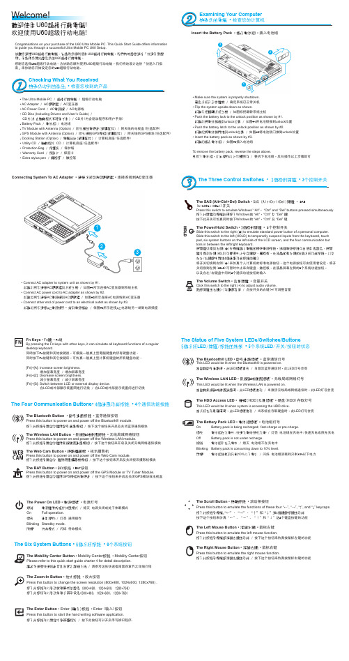
Insert the Battery Pack • 插入電池組 • 插入电池组• Make sure the system is properly shutdown. 確定系統已正常關機 / 确定系统已正常关机• Flip the system upside down as shown.如圖示把翻轉系統主機 / 如图标把翻转系统主机 • Push the battery lock to the unlock position as shown by #1.如圖#1將電池鎖推到unlock 位置 / 如图#1将电池锁推到unlock 位置• Push the battery latch to the unlock position as shown by #2.如圖#2將電池鎖閂推到unlock 位置 / 如图#2将电池锁闩推到unlock 位置• Insert the battery pack as shown by #3. 如圖#3插入電池組 / 如图#3插入电池组To remove the battery pack, reverse the steps above.要拆下電池組,反向操作以上步驟即可 / 要拆下电池组,反向操作以上步骤即可Welcome!歡迎使用U60超級行動電腦!欢迎使用U60超级行动电脑!Congratulations on your purchase of the U60 Ultra Mobile PC. This Quick Start Guide offers information to guide you through a successful Ultra Mobile PC U60 Setup.感謝您選擇U60超級行動電腦。
為協助您順利使用U60超級行動電腦,我們特地設計這份「快速安裝說明」來協助您開始設定您的U60超級行動電腦。
感谢您选择U60超级行动电脑。
【T61R61X61安装WinXP详细教程
【T61R61X61安装WinXP详细教程电脑直销免费咨询电话 800 858 2293ThinkPad T61/R61/X61系列硬件架构相当接近,原厂维修手册都可共享,此篇安装流程理论上可以适用在ThinkPad T61/R61/X61系列上面,记得再根据个别机种的硬件安装对应驱动程序。
ThinkPad 全系列机型驱动程序矩阵列表由于微软的许多组件都需在线下载,无法直接下载完整版本,因此才会视需要,将网络卡的驱动程序安装程序放在前面。
此外ThinkPad 的相关驱动程序也有安装顺序上的考虑,以下的安装流程其实已经把各环节都尽量考虑进去,如网友没有把握,不妨按照以下的顺序安装,感谢。
准备动作、设定 SATA 硬盘自从 T60/R60/X60 开始改用 SATA 界面硬盘,手动安装 WinXP 便遇到一个问题:「要选择Compatibility 还是AHCI 模式?」,这问题的主因源自于设定为 AHCI 模式时,必须在安装时按下「 F6 」,然后预先加载芯片组驱动程序。
但现在拥有 USB 界面软驱的使用者实在太少了。
在没有USB 软驱的状况下,有的使用者便设定成「Compatibility 模式」,却发现硬盘效能不彰,接着去BIOS 调回AHCI 模式之后,就会发生蓝底白字的系统当机惨剧。
因此很多人想到要重装 WinXP 就头大。
但根据Lenovo 原厂提供的资料,以及亲身体验,其实手动安装WinXP 并不困难!不需要准备 USB 软驱﹔不用忍受「 Compatibility 模式」效能不彰问题,更不会发生蓝底白字惨剧,关键只在于「安装流程的顺序!」请跟着本文的流程依序安装,相信大家都能顺利重返 WinXP 环境!1. 按下电源开关,开机时请按「 F1 」键,之后会进入 BIOS 画面。
2. 进入 BIOS 之后,进入「 Config 」页面3. 再进入「 Serial ATA(SATA) 」页面4. 将原先的「 AHCI 」改成「 Compatibility 」换言之,手动安装 WinXP 时,先采用「 Compatibility 模式」,规避掉需要透过 USB 软驱安装驱动程序的困扰,然后在后面的「步骤三」请网友务必按照说明安装 Intel Matrix Storage Manager Driver ,同时将硬盘更改为 AHCI 模式。
NC600快速安装手册
售后服务:包括技术支持和维修查询。维修查询为您提供24小时网上实时监控维修进度,您可以在这里查询您送修的维修品状况以及预 计返回时间。
TCP/UDP Socket模式的问题 1. 作为[TCP Server]时,不能被连接
解决办法 (1)确认没有别的PC与串口通讯服务器的相应端口有连接:进入串口通讯服务器的[统 计]查看[活动TCP信息] (2)[详细参数]中的[认证]是否为[none] 2. 作为[TCP Client]时,不能建立连接 解决办法 (1)检查要连接的TCP Server是否能够正确响应连接:可通过在WINDOWS下运行telnet + ip + tcp port的方式检测 (2)检查详细参数中的 [发起连接],看当前状况是否满足发起连接的条件。
把光标移动到 [保存当前设置] 回车,可实现参数的保存。保存成功后,把光标移动到 [重启设备] 回车,实现 NC600 重新启动,使设置的参 数生效。
也可通过网页的形式进行快速配置
IO-Server
故障排查 通过网络设置和维护串口通讯服务器时,可能遇到的常见问题 1. 用 [upgrade]程序 不能搜索到串口通讯服务器
4. 串口通讯服务器作为拨号服务器,连接已正常建立,但是客户端的PC用IE在地址栏目 输入域名打开网页时,总不能打开;在地址栏目输入IP地址时,能打开 解决办法 (1)串口通讯服务器中[PPP daemon]的[详细参数]中[分配DNS服务器]是否为‘Yes’;在[服务器]中设置的DNS是 否真实有效
对讲机设置LT6100设置频率的方法

LT6100设置频率的方法(上下行、哑音全设置)发表于2009年03月02日 21:10 阅读(40) 评论(0) 分类:1、按[V/M]键进入全频模式(VFO模式)。
按数字键输入需要的下行频率。
2、按[F]+[5]键选上差“+”还是下差“-”,反复按[F]+[5]键即可依次实现“+” “-” 和不选。
3、按[F]+[9]键进入选单模式,再按上下箭头到第16选单,再按[F]键进入修改模式,输入需要的差频值,按[F]键确认,按除侧面的两个小键以外的任一键退出,至此上下行频率已经设好。
4、按[F]+[6]键设置哑音,按上下箭头依次是“OFF”、“TONE”(发射带模拟亚音,接收没带模拟亚音)、“CTCSS”(发射接收都带模拟哑音)、“D CODE”(发射带数字哑音,接收没带数字亚音)、“DCS”(发射接收都带数字哑音)、“T DCS”(发射模拟哑音,接收数字哑音)、“D TSQL”(发射数字哑音,接收模拟哑音),选好后按[F]键确认,屏幕右上角应该出现‘CT“或“DCS”字样。
5、按[F]+[7],进入哑音值设置菜单,按上下箭头键选应该设置的数值,选好后按[F]键确认。
对于“CTCSS”和“DCS”“T DCS” “D TSQL”需要分别设置接收和发射的亚音值,而“TONE”和“D CODE”只需设置发射的亚音值。
6、设置完成后,按[F]键,左上角的“001”和左下角的“F”同时闪烁,可按上下箭头键选要存入的信道,最后按[V/M]存储。
记住,一定要按[V/M]键才能存储。
通话结束提示音当这个功能打开时,在通话结束时会有通话结束提示音,使通话的双方知道已经通话结束了。
缺点是只有一种提示音,没有可选的。
按[F]键,再按[9],进入选单模式,按上下键找到第20项“ROGER”,再按[F],用上下键选择“on”后,按任意键退出选单模式。
[img,17,19 语音加密功能当这个功能打开时,对通话进行加密,通话的双方必须都使用加密功能,才能听的清楚。
JK-TX-GSTN6100传输设备用户信息传输装置安装使用说明书

安装、使用产品前,请阅读安装使用说明书。
请妥善保管好本手册,以便日后能随时查阅。
JK-TX-GSTN6100传输设备/用户信息传输装置安装使用说明书(Ver.1.06,2020.11)注意:产品仅应被安装在产品安装使用说明书所明示规定的使用环境,不适用于有爆炸性气体或有腐蚀性气体的场所(包括使用磷化铝杀虫剂的烟草仓库)。
产品不可被安装在对设备有特殊认证要求的环境或场所(包括但不限于爆炸性环境、船舶、飞机、火车、机动车等交通工具)。
如有特殊需求,请联系本公司相应销售人员。
前言JK-TX-GSTN6100传输设备/用户信息传输装置是海湾公司充分调研消防市场需求,总结多年消防工程经验,融会国标GB 26875《城市消防远程监控系统》、GB 16806-2006《消防联动控制系统》和GB 26875.1-2011《城市消防远程监控管理中心第1部分:用户信息传输装置》的要求和精神设计的新一代用户信息传输装置。
JK-TX-GSTN6100传输设备/用户信息传输装置采用壁挂式结构、模块化设计,具有功能强、易维护、配置灵活的特点。
系统不仅能接收用户的火灾报警系统的火警、故障、屏蔽等信息,而且能接收到用户的建筑消防设施如消火栓系统、灭火系统、应急广播系统等的运行状态信息。
JK-TX-GSTN6100传输设备/用户信息传输装置提供开关量、RS232、RS485多种对外接口与外设连接,通过TCP网络、GPRS/CDMA无线网络或二者互为备份的通讯方式接入到我公司的城市消防远程监控系统中,是提高城市消防水平的最佳选择。
目录前言 (I)第一概述 (1)第1章产品简介 (1)1.技术新、可靠性高 (1)2.窗口化、汉字菜单式显示界面 (1)3.灵活的模块化结构 (1)4.具备自诊断功能 (1)5.模块式开关电源 (1)第二结构.安装.调试 (2)第2章结构、安装与调试 (2)2.1开箱检查 (2)2.1.1工程配置检查 (2)2.1.2传输装置内部配置及连接状况检查 (2)2.2传输装置的安装条件及方式 (2)2.3外观说明 (2)2.4开机检查 (3)2.5调试 (3)第三系统应用 (5)第3章一般用户使用说明 (5)3.1开机、关机与自检 (5)3.2键盘操作 (6)3.2.1键盘的命令功能和字符功能 (6)3.2.2数据输入的一般方法 (6)3.2.3主界面下的键盘操作 (6)3.2.4子菜单界面下的键盘操作 (7)3.3键盘解锁和锁键盘 (7)3.3.1键盘解锁 (7)3.4外设火警及手动火警 (7)3.5其他信息 (10)3.6与中心通讯的处理 (10)3.7火警及故障的处理 (10)3.7.1故障的一般处理方法 (10)3.7.2报警的一般处理方法 (10)3.8状态指示 (11)3.9巡检功能 (12)3.10状态查询 (14)3.11历史记录查询功能 (14)第4章系统管理员操作指南 (17)4.1默认设置 (17)4.2系统设置 (17)4.2.1编码报名 (17)4.2.2开关属性 (18)4.2.3报警延时设置 (18)4.2.4连接设置 (19)4.2.5防盗设置 (20)4.2.6校对时间 (20)4.2.7无线设置 (20)4.2.8传输设置 (21)4.3更改密码及初始化 (23)4.3.1系统初始化 (23)此时按“确认”键执行清除记录操作,按“取消”键返回上一级。
WEST6100中文简明安装及操作说明书

3. MESSAGES/ERROR INDICATION(信息和错误指示)这些信息表明有错误发生,或者表明过程变量的信号或其线路有问题。
该信息只是提供帮助,并不能替代操作人员及安装人员的安全责任。
小心:请首先解决问题,然后再继续工作。
置后,将看到该屏幕。
按进入 Configuration(配)模式,接着按或继续4. 串行通讯有关详细信息,请参考完整的用户指南(可以向您的供应商索取)。
5. OPERATOR(操作员)模式在加电时会进入该模式,也可以从 Select(选择)模式进入。
注意:开始常规操作之前,必须根据应用的要求对所有的 Configuration(配置)模式和 Setup(设置)模式参数进行设置。
按滚动参数,然后按或设置所需要的值。
注意:显示策略 6 下的所有 Operator(操作员)模式参数均为只读(请参阅 Configuration(配置)模式中的 diSP),它们只能通过 Setup(设置)模式来进行调整。
上显示屏下显示屏显示策略及可见时间说明PV 值当前有效的 SP 值1 和 2(初始屏幕)PV 值和所选 SP 的目标值在显示策略 2 下可调整设定值PV 值实际的 SP 值 3 和 6(初始屏幕)PV 值和所选 SP 的实际值(比如斜坡时的SP 值)。
(只读)PV 值(空白)4(初始屏幕)仅显示过程变量。
(只读)当前有效的SP 值(空白)5(初始屏幕)仅显示设定值的目标值。
(只读)SP 值SP1,3,4,5和6所选 SP 的实际值。
只读实际的SP 值SPrp rP 不为OFF所选 SP 的实际(斜坡)值。
只读斜坡速率rpSpr 在设置模式中被使能SP斜率,单位/小时,可调(显示策略6除外)激活的报警状态ALSt当存在一个或多个活动报警时。
上行将显示ALM 并闪烁报警 2 激活L21 报警 1 激活回路报警激活警告报警被激活ALdG诊断故障报警123i1 = 如果输出1的记数报警动作2 =如果输出2的记数报警动作3 =如果输出3的记数报警动作i = 如果环境超温报警动作输出锁存报警被激活ALOL输出锁存报警OL1_ =锁存 输出1报警动作OL_2 =锁存 输出2报警动作OL12 =锁存 输出1或2报警动作程序段号SGnb程序运行状态下当前运行程序的程序段号(只读)目标设定值SGtS程序运行状态下当前程序段的目标设定值(只读)剩余时间SGtr程序运行状态下当前程序段剩余时间。
一、快速安装指南

一、快速安装指南1.桌面上放置软垫,将速拍仪放置在软垫的示意位置,并掀起拍摄翻盖至水平 2.启动电脑后,将 USB 电缆方头的一端插到速拍仪底座上,电缆另一端的扁头插到电脑的 USB 端口上,电脑接口必须是高速 USB 2.0。
3.将速拍仪安装光盘放入电脑光驱,电脑会自动执行安装程序。
请根据屏幕上的提示和实际需求进行安装。
4.双击桌面上的速拍仪图标,启动速拍仪软件进行拍摄。
二、电脑系统需求Pentium 4 1.6 CPU 或更高,512 MB 以上内存,200 MB 硬盘空间,USB2.0 接口。
Windows XP-SP2 / Vista/Seven 操作系统(简体中文、繁体中文,英文)。
三、《速拍仪》软件介绍及基本使用方法1.启动:双击桌面上的速拍仪图标,启动《速拍仪》软件。
2.设置 1:选择拍摄界面,根据实际需求设置拍摄参数。
通常只设置,文件类型:BMP、JPG 等图片文件格式;颜色格式:彩色、灰度、黑白,并指定拍摄图像的保存位置。
3.设置 2:通常勾选“自动曝光”和“自动裁切纠偏”,这样可以很方便的拍摄各种题材和幅面的文档。
文档从最大幅面直至名片大小,即使没有摆正、没有放在视野中心,只要完全放置在拍摄视野内,按下“拍摄”按钮后都可以拍摄出没有黑边、不歪斜的图像。
为保证裁切准确,适当调整速拍仪底座位置,使速拍仪视野内只有深色(或稿垫背面黑色)的稿垫,不要让速拍仪“看”到稿垫的边缘、桌子的边缘。
4.连拍:大量快速拍摄时还可选择“连拍”,只要文档放置稳定后,速拍仪就自动拍摄一张,只需更换文档不用再次按钮操作,快捷方便。
5.光照:速拍仪安放位置应选择在光照均匀、拍摄视野内没有光斑、阴影的位置,如果拍摄的文档中有反光(特别是光亮的和反光的文档),请适当调整速拍仪或文档的位置,避开反光。
照明不足时可以按动速拍仪底座上的开关开启速拍仪的照明灯。
四、拍摄界面介绍【浏览】点击该按钮可以指定拍摄图像文件的存储位置。
lkoa操作手册

输入正确,将进入系统的主界面(个人桌面),登录后的主页面(个人桌面)如下图:此首页(个人桌面)页面中,显示与当前操作员有关额员工待办事宜列表个人办公工具等相关信息。
在此首页页面的上方有几个操作图片和链接,其中:点击可显示或隐藏页面左边的功能菜单列表。
点击可重新进入此‘个人桌面’(见‘个人桌面’说明)。
点击可进入短消息和定时提醒管理(见收发短消息和定时提醒说明)。
如果有员工向当前操作员发送消息,则其会开始闪动,同时会有声音提醒;点击进入即可查看相应的消息内容,当所有的消息均已查看完毕后,会自动停止闪动。
点击则重新显示(刷新)当前正在工作的页面内容。
点击则返回到前一个操作页面。
点击则转到下一个操作页面。
点击退出LKOA系统,返回到系统登录页面。
在标题栏中,点击当前操作员的姓名,可显示当前操作员的详细个人信息。
点击‘当前有XX用户在线’可查看当前正在使用LKOA系统的人员情况,如下图:点击某一离线人员的‘离线(详细)’链接,可查看该员工的离线留言信息。
级机构设置是一次性的。
一旦设置完以后是不能删除的,只能修改。
如果您不是首次进入且已经配置好了顶级机构信息,您看到的将是如下的登录界面:如果登录口令输入错误,您看到相应的登录出错提示信息页面,并要求重新输入登录密码。
如果登录口令输入正确,您看到的将是带TreeView引擎的管理页面(如下图):界面右方显示的是公司的体系结构,顶级机构在最上层,下面是各个部门的名称,部门可以是多级的,即部门下面可以有子部门,顶级机构下面的部门叫做一级部门,以此类推。
界面左方白色背景的就是TreeView引擎管理器,所有的部门、人事、职位等信息的设置都是由它来作导航。
它的结构以及操作方法类似于Windows的资源管理器,都是按层次列出每个节点,单击节点,可以在界面的右方浏览或编辑详细信息;双击节点或单击收缩开关(代表未展开、代表已展开)就可以展开或收缩当前节点。
在顶级机构下分层次列出了其下的所有部门以及部门下面的人员信息,在每个节点上显示的内容是机构或部门的名称,名称后面的‘姓名’代表该机构或部门的主管。
W321 341嵌入式计算机快速安装指南(第六版,2013年4月)说明书

– 1 –– 2 –– 3 –P/N: 1802003116015W321/341-LX Quick Installation GuideSixth Edition, April 20131. OverviewThe W321/341 embedded computers feature 2 or 4RS-232/422/485 serial ports, 1 Ethernet port, 4 DI/DO (W321 only), an embedded 802.11 b/g/n wireless LAN module, and an SD socket interface for storage expansion, making the W321/341 ideal for compact, wireless embedded applications.2. Package ChecklistPlease verify that the package contains the following items: • 1 W321/341 embedded computer • Quick Installation Guide • Document & Software CD• Ethernet Cable: RJ45 to RJ45 cross-over cable, 100 cm• CBL-4PINDB9F-100: 4-pin header to DB9 female console port cable, 100 cm • WLAN Antenna• Universal Power Adaptor• Product Warranty StatementOptional Accessories•35 mm DIN rail Mounting Kit (DK-35A)3. W321/341 Panel LayoutW341-LXW321-LXLED IndicatorsThe following table describes the LED indicators located on the front panel of the W321/341.If you find a weak wireless communication (where the signal strength indicates “Bad”), we suggest you install the W321/341 computers at some other place within a stronger wireless signal range, or boost the signal by installing another wireless access point or bridge.4. Installing the W321/341Wall or Cabinet MountingThe W321 have built-in “ears” for attaching the embeddedcomputers to a wall or the inside of a cabinet. We suggest using two screws per ear to attach the W321/341 to a wall or cabinet.The heads of the screws should be less than 6.0 mm in diameter, and the shafts should be less than 3.5 mm in diameter, as shown by the figureat the right.The W341 comes with two metal attachment plates for attaching the embedded computer to a wall or the inside of a cabinet. First, use two screws per bracket to attach the brackets to the rear of the W341. Next, use two screws per bracket to attach the W341 to a wall or cabinet. DIN Rail MountingDIN rail attachments can be purchased separately to attach the product to a DIN rail. When snapping the clips onto the DIN rail, make sure that the stiff metal springs are at the top.Wall or MountingDIN rail Mounting5. Connector DescriptionPower ConnectorConnect the 12 to 48 VDC LPS or Class 2 power line to theW321/341’s terminal block. If the power is properly supplied, the Power LED will light up. The OS is ready when the Ready LED glows a solid green.– 4 – – 5 – – 6 –/supportThe Americas: +1-714-528-6777 (toll-free: 1-888-669-2872)Europe: +49-89-3 70 03 99-0 Asia-Pacific: +886-2-8919-1230China:+86-21-5258-9955 (toll-free: 800-820-5036)2013 Moxa Inc. All rights reserved.Grounding the W321/341Grounding and wire routing help limit the effects of noise due to electromagnetic interference (EMI). Run the ground connection from the ground screw to the grounding surface prior to connecting the power.Shielded Ground:The shielded ground (or SG , sometimes called protected ground ) contact is the leftmost contact of the 3-pin power terminal block, when viewed from the angle shown here. Connect the SG wire to an appropriate grounded metal surface.Ethernet PortsThe 10/100 Mbps Ethernet port uses RJ45 connectors.Serial PortsThe serial ports use DB9 connectors. Each port can be configuredby software for RS-232, RS-422, or RS-485. The pin assignments for the ports are shown in the following table:SD SlotThe W321/341 has an internal SD slot for storage expansion. The SD slot allows users to plug a Secure Digital (SD) memory card compliant with the SD 1.0 standard for up to 1 GB of additional memory space, or a Secure Digital High Capacity (SDHC) memory card compliant with the SD 2.0 standard for up to 16 GB ofadditional memory space. Use a screw driver to remove the SD slot cover to access the slot. The slot is located on the right panel of the W321/341. Plug the SD memory card directly into the socket, and then replace the SD slot cover. The SD card will be mounted at /mnt/sd . To remove the SD card from the slot, gently push theSD card further into the slot and then remove the pressure to allow the card to spring out. You may then remove the card. DI/DOThe W321 comes with 4 digital input channels and 4 digital output channels. The DI/DO connectors is an array of five pairs of pin headers located on the right side of the computer. See the following figures for pin assignments.Console PortThe serial console port is a 4 pin header RS-232 port. It is designed for serial console terminals, which are useful for viewing boot-up messages. Use the CBL-4PINDB9F-100 cable included with the product to connect a PC to the W321/341’s serial console port. ResetPress the Reset button and hold it in for at least 5 seconds to load the factory default configuration. After killing all running processes, the system will take several seconds to synchronize its software to factory defaults. After the default configuration has been reloaded, the system automatically reboots. The Ready LED will blink on and off for the first 5 seconds, and then maintain a steady glow once the system has rebooted. Real-time ClockThe W321/341’s real-time clock is powered by a lithium battery. We strongly recommend that you do not replace the lithiumbattery without help from a qualified Moxa support engineer. If you need to change the battery, contact the Moxa RMA service team.6. Powering on the W321/341To power on the W321/341, install theterminal-block-to-power-jack converter on the W321/341’s DC terminal block (located on the left rear panel), and then connect the power adaptor. Note that the ground/earthing wire should connect to the rightmost pin of the terminal block. It takes about 30 seconds for the system to boot up. Once the system is fully booted the Ready LED will light up.7. Connecting the W321/341 to a PCThere are two ways to connect the W321/341 to a PC: (1) through the serial console port, or (2) by SSH console over the network.The COM settings for the serial console port are: Baudrate = 115200 bps, Parity = None, Data bits = 8, Stop bits = 1, Flow Control = None.To access the SSH console, you will need to know the W321/341’s IP address and netmask. The default LAN settings are shown below. For first-time configurations you may find it convenient to use a crossover Ethernet cable to connect directly from the PC to the W321/341.Default IP Address Netmask LAN 1192.168.3.127 255.255.255.0 LAN 2 (wireless)192.168.4.127 255.255.255.0Once the W321/341 is powered on, the Ready LED will light up and a login page will open. Use the following default username and password to proceed. The defaults are: Login: rootPassword: root8. Configuring the Ethernet InterfaceTo configure the Ethernet interface, use the following commands. Please note that etho0 stands for the IP address of the LAN port, wlan0 stands for the IP address of the wireless LAN.ifconfig eth0 192.168.3.127 ifconfig wlan0 192.168.4.127NOTE Refer to the W321/341 User’s Manual for information on how to configure the WLAN interface, and for other configuration information.。
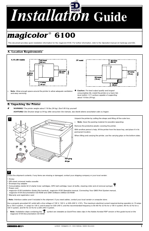
magicolor 6100 安装指南说明书
PDJLFRORU ®943314;339830334$This document provides quick installation information for the magicolor 6100. For further information, refer to the Operation manual (in hardcopy and CD).$1/RFDWLRQ 5HTXLUHPHQWV%18QSDFNLQJ WKH 3ULQWHUWARNING! The printer weighs about 119 lbs (54 kg). Don’t lift it by yourself.ACHTUNG! Der Drucker wiegt ca 54 kg; bitte versuchen Sie niemals, das Gerät alleine anzuheben oder zu tragen.EDNord - Istedgade 37A - 9000 Aalborg - telefon 96333500magicolor 6100 Print System! "" # $Caution:Do not hold the toner cartridge vertically.Remove the tonercartridges from theirshipping cartons.Holding a cartridge withboth hands, gently rock itfive or six timeshorizontally.Pull the tab to remove thetape.Remove the orangeprotective cover from eachcartridge.Press the front cover latchon the upper-right side ofthe printer and open theprinter’s front cover.Align the toner cartridgewith the cartridge guides.Gently push the cartridgeinto the printer.Caution:Each tonercartridge has a coloredlabel that correspondsto a colored label to theright of the cartridgeslots. Always install thetoner cartridge in theslot with a label of thesame color.Install the other tonercartridges.»Note: Leave the printer’s front cover in the open position while installing theOPC Belt Cartridge as described in the next section.% ! "" & " $Caution:The OPC belt is extremely sensitive to bright light and touch. Always leave it in its protective box until you’re ready to install it. Any exposure to light should be limited to less than two minutes or permanent damage could result. Always handle the cartridge by its sides so you don’t touch the surface of the belt.Rotate up the two lock levers to prepare the opening for the cartridge.Caution: Make sure the printer’s front cover isstill open.Pull out the two tension-release pins (one on each side of the cartridge).Remove the protective sheet from the cartridge.»Note: The white powder lubricant on a new OPCbelt is normal; it won’taffect quality.Holding the cartridge above the printer, align the guide pins on the cartridge with the guide slots in the lock levers.The green surface of the cartridge faces you.Caution: Whenlowering the cartridgeinto the guide slots, themetal contact on thelower left side of thecartridge should bealigned outside of theleft guide slot.Gently guide the cartridge into the printer.Rotate the two lock levers toward the back of the printer to secure the cartridge in the printer.12 345# $ # %1234EDNord - Istedgade 37A - 9000 Aalborg - telefon 9633350023magicolor 6100 Print System (continued)' ! "" ( & " " $ " ""Open the two cleaningroller lock levers by rotating them toward each other.Push the two tension release levers toward the rear of the printer.»Note: The printer isshipped with the tension release levers in the forward position.Install the cleaning roller in its slot.Close the two lock levers.Open the two oil bottle lock levers by rotating them away from each other.Insert the new oil bottle with the nozzle pointed down.Close the two lock levers. Close the printer’s top and front covers.( $ ) $Unpack the media cassette. Adjust the media guides to fit the size paper you’re loading.Squeeze the retainers at the ends of the left guide, move the guide to theappropriate location (media sizes are listed on the cassette).Release the retainers.Squeeze the retainers at the ends of the centerguide, and move the guide to the appropriate location.Release the retainers.Push the media pressure plate down to lock it in position.Fan a stack of approx-imately 250 sheets (½ ream) of letter-size paper.Load the paper.Caution: The paper should fit easily between the guides. Make sure the paper corners are not bent.A fill limit mark is provided on the inside left side of the cassette.Caution: Do not over-fill the cassette.The paper should face up with its top toward the right of the cassette.Slide the media cassette back into the printer.* ! "" + ( $ , ( - Caution : Unplug the printer’s AC power cord before performing the followingsteps.(Skip to “I. Connecting Interface and Power Cables” if you didn’t purchase a lower input feeder or duplex unit.)Check the lower input feeder kit contents:•Input feeder unit•Universal media cassette•One small metal bracket with thumbscrew (attached to LFU)•Two plastic side coversRemove the feeder from the shipping carton.» Note: One or two lower feeder units may be installed on the magicolor 6100Print System. The following steps apply to both single and dual LFU kit installations except where noted.WARNING! If consumables are installed, be sure to keep the printer level when moving it to prevent accidental spills.ACHTUNG! Achten Sie bitte darauf, das der Drucker mit eingebauten Tonerkartuschen nur waagerecht transportiert wird.Move the LFU(s) to a table or flat surface near the printer.Position the LFU cable connector away from the rear of the LFU.1&' % ! $ %23&4# & !(1!() " ( "23412EDNord - Istedgade 37A - 9000 Aalborg - telefon 96333500magicolor 6100 Print SystemLocate the front and rear positions of the positioning pins on the LFU, and make sure the metal coupler is in the open position.For dual LFU installations: After verifying that both metal couplers are inthe open position, align the positioning pins and set one LFU on top ofthe other.Set the printer on top of the input feeder.Be sure to align the printer and LFU as precisely as possible. Make sure the printer is not tilted on top of the LFU.Remove the printer’s connector access cover from the bottom left side of the printer by sliding the cover down and then out. The connector access cover is replaced by the left side cover of the LFU.Install the metal bracket underneath the side of the printer just below the connector.Holding the bracket at a slight angle, slide it upinto the hole underneath the printer before settingit to vertical.Make sure that the hole in the metal bracket is lined up with the corresponding hole on the input feeder.Tighten the thumbscrew to attach the bracket to the lower input feeder.For dual LFU installations: After completing the above steps, repeat the bracket installation between the lower and upper LFU.Remove the cassette from the printer.You should be able to see the metal coupler at the front upper-right corner of the printer’s cassette slot. Push the handle of the metal coupler around so the hook is attached to the slot on the printer.For dual LFU installations: In addition to the above instructions, close the metal coupler inside of the top-most LFU’s cassette slot to secure the two LFU’s together.Connect the LFU cable to the white printer connector. For dual LFU installations: Complete the above instructions and connect the lower LFU cable to the upper LFU connector.Install the right side cover(s).3!) (" " "45* % 6098mati.eps7 89EDNord - Istedgade 37A - 9000 Aalborg - telefon 9633350045magicolor 6100 Print System (continued)Install the left side cover(s).Attach the rotation slot on the cover to the rotation pin on the LFU.Rotate the left side cover to snap it into place on the printer.Adjust the two anchor feet on the right side of the LFU to level the printer.For dual LFU installations: Adjust both the upper and lower LFU anchor feet to level the printer.. ! "" % " /»Note: At least one lower feeder unit must be installed on the printer before the duplexer unit can be installed. Caution : Unplug the printer’s AC power cord before performing the following steps.Remove the duplex unit from its shipping box .Remove the shippingspacer from the bottom of the duplex unit.Retain all packagingmaterials for future storage and shipping use.Remove the upper paper exit cover from the top-rear of the printer.Using a flat-bladedscrewdriver or small coin, remove the two plugs from the rear of the printer by gently prying outward from the plug slots.Facing the back of the printer, remove the two access plates located on the rear, inside panels of the LFU by sliding them toward you.Open the duplexing unit top cover.Attach the duplex unit by aligning the pins with the slots located at the lower rear of the LFU.Push the top of the duplex unit toward the printer to snap it into place against the rear printer casing.Fasten the twothumbscrews to lock the duplexing unit into place.Close the duplexing unit top cover.10111+ "" ! "2*(!,"" " " - %' " %34' ( . /EDNord - Istedgade 37A - 9000 Aalborg - telefon 963335006magicolor 6100 Print SystemRemove the left side cover from the printer.Connect the duplex unit cable to the blackconnector at the left rear side of the printer.Reattach the left side cover.! ! 0 $ + 1"Refer to the Connecting Your QMS Print System manual for instructions on how to connect your printer to a computer or network.»Note: The printer requires a brief warmup (typically 3 minutes).Plug the printer into agrounded, surge-protected electrical outlet.»Note: In compliance with UL guidelines, “The appliance inlet is considered to be the main disconnect device.”A startup page should print when the printer is turned on.2 0See the Connecting Your QMS Print System manual for instructions on installing the QMS printer e the on line help to configure the driver for printing.See the magicolor 6100 Operation manual for further instructions on advanced printerconfiguration through the control panel menus.(Internet —Visit the QMS Product Registration page on the Internet at /support/prodreg/.Mail —Fill out and send in the warranty card enclosed in your shipment.Refer to one of the following:•magicolor 6100 Operation manual.•Appendix A, “QMS Customer Support,” in any magicolor Print System manual.# $ $ 3 4QMS, magicolor , and the QMS logo are registered trademarks of QMS, Inc. Adobe, Acrobat, the Acrobat logo/Adobe Systems Incorporated.This docu ment is Copyrighted © 2000 by QMS, Inc., One Magnum Pass, Mobile, AL 36618. All Rights Reserved. This document may not be copied in whole or in part, nor trans-ferred to any other media or language, without the express written permission of QMS, Inc.56121。
