B系列快速安装指南
戴尔PowerEdge服务器快速安装指南.pdf_1701143394.591269说明书
Software Quick Installation Guide w w w.d e l l.c o m|s u p p o r t.d e l l.c o mNotes and NoticesNOTE: A NOTE indicates important information that helps you makebetter use of your computer.NOTICE: A NOTICE indicates either potential damage to hardware or loss of data and tells you how to avoid the problem._________________Information in this document is subject to change without notice.©2006Dell Inc.All rights reserved.Reproduction in any manner whatsoever without the written permission of Dell Inc. is strictly forbidden.Trademarks used in this text: Dell, the DELL logo, and PowerEdge are trademarks of Dell Inc.; Microsoft and Windows are registered trademarks of Microsoft Corporation. Other trademarks and trade names may be used in this document to refer to either the entities claiming the marks and names or their products. Dell Inc. disclaims any proprietary interest in trademarks and trade names other than its own.January 2006P/N CC114Rev. A00This document is available on the Dell PowerEdge SC Server Installation CD and the Dell PowerEdge SC Server Documentation CD in English, French, German, Spanish, Japanese, andSimplified Chinese.Verifying the Software Kit ContentsThe system support software kit includes, but is not limited to, the following components:•The Dell PowerEdge SC Server Installation CD contains the tools you need to configure your system and install youroperating system. This CD also delivers the latest diagnostics and Dell-optimized drivers for your system.•The Dell PowerEdge SC Server Documentation CD includes documentation for your Dell™ PowerEdge™ SC system,peripherals, and RAID controllers.Compare the contents of your system accessories box with the packing slip or invoice enclosed with your system. If any components are missing or damaged, call Dell within 30 days of the invoice date for a free replacement. For more information, see"Obtaining Technical Assistance."34Installing and Configuring the Server and Operating System Perform the following steps to determine if an operating system is already installed on your system:1Ensure that the keyboard, mouse, and monitor are connected to your system, and turn on your system.2Read and accept the software license agreement to continue. If a message appears and states that bootable drives do not exist or that an operating system was not found, then an operating system is not installed on your system. Have youroperating system CD available and continue with step 3. NOTE: If an operating system is already installed on yoursystem, it is not necessary to continue with this process.To complete the installation process, locate theInstallation Instructions document that was provided withyour system and follow these instructions.3Insert the Dell PowerEdge SC Server Installation CD and restart your system.The following options are available during system boot:•Server Assistant — Boots through the CD.•Server Assistant with CD media check — Checks if the CD is created correctly and for validity of content.•Skip CD boot - Boot to hard drive — Boots from the hard drive and verifies if an operating system is installed onyour system. If an operating system is not installed onyour system, boots through the CD.NOTE: If you do not select an option within 10 seconds, thesystem automatically boots through the CD.4Select the language that you want to use.5Read and accept the software license agreement to continue. 6Select Server Setup on the System Support main page.7Follow the step-by-step instructions to configure your hardware and to install your operating system.5Updating Drivers and UtilitiesThe Dell PowerEdge SC Server Installation CD contains device drivers and system utilities that you can use to update your system. Use this CD to locate and extract the drivers designed for your system.NOTE: To update drivers and utilities, you can run the DellPowerEdge SC Server Installation CD only on systems running theMicrosoft® Windows® operating system. To extract drivers for systems that are not running Windows, you must first use this CD on a system running Windows and then copy or share the selected files to thefinal destination system.1Insert the Dell PowerEdge SC Server Installation CD into the CD drive on the system running Windows.The setup program should start automatically. If it does not,click the Start button, click Run, and then type x:setup.exe (where x is the drive letter of your CD drive).2Select the system and the file set that you want to update and click Continue.63Click the file name of the file you want to update.Y ou are prompted for a location to save the file.Files are delivered in compressed format. Running thecompressed file either creates a diskette(s) duringthe extraction or prompts you for the location to save theextracted files.Obtaining Technical AssistanceBefore contacting Dell for technical assistance, see theDell Support website at . If you need additional technical support, see "Getting Help" in your system's Hardware Owner’s Manual for country/region-specific information about contacting Dell by using telephone, fax, and Internet services. Antes de entrar em contato com a Dell para obter assistênciatécnica, consulte o site de suporte na Web: . Você precisará do número da sua etiqueta de serviço para identificação de seu equipamento. Caso necessite de suporte técnico adicional, é fornecida assistência técnica para hardware ao proprietário original do equipamento. Esse serviço está disponível de segunda asexta-feira, das 7 às 19:00h, em português. Telefone: 0800-90-3355.7For the latest product updates, such as drivers and patches, go to the Dell Support website at .Dell Enterprise Training and Certification is available now; see /training for more information. This service may not be offered in all locations.8。
Backup Box-(B0, B1) 快速安装指南说明书

Backup Box-(B0, B1) Quick GuideIssue: 04Date: 2023-02-1511.The information in this document is subject to change without notice. Every effort has been made in the preparation of this document to ensure accuracy of the contents, but all statements, information, and recommendations in this document do not constitute a warranty of any kind, express or implied.2.Before installing the device, read the user manual carefully to get familiar with product information and safety precautions.3.Only certified electricians are allowed to operate the device. Operation personnel must wear proper personal protective equipment (PPE).4.Before installing the device, check that the package contents are intact and complete against the packing list. If any item is missing or damaged, contact your dealer.5.The device damage caused by the violation of instructions in this document is not covered under warranty.6.The cable colors involved in this document are for reference only. Select cables in accordance with local cable specifications.FunctionThe Backup Box is used in a residential rooftop PV plant system to control the inverter grid-tied or off-grid state. When the grid fails, the inverter switches to the off-grid state and supplies power to off-grid loads in backup mode. When the grid recovers, the inverter switches back to the grid-tied state.Model NumberNo.Meaning Value1Product name Backup Box: Backup Box 2Design codeB0: single-phase B1: three-phaseSystem NetworkingThe grid-tied system of a rooftop PV plant consists of PV strings, an energy storage system (ESS),an inverter, a Backup Box, a management system, an AC switch, and a power distribution unit.Supported Grid TypesThe Backup Box supports the following grid types: TN-S, TN-C-S and TT. When the inverter is inthree-phase, three-wire mode, the Backup Box does not support off-grid operation.•Off-grid electric motor loads are not supported. The startup power of an electric motor is several times of its rated power, which may exceed the load capacity of the Backup Box, resulting in startup failure.•The off-grid load port cannot be directly connected to the power grid. Otherwise, the off-grid function is unavailable, causing shutdown upon overload.•The power of off-grid loads cannot exceed the maximum off-grid output power of the inverter.Appearance(1) Front panel(2) Lock(3) Hanging kit(4) Off-grid load port (BACKUP LOAD)(5) Grid AC port (GRID)(6) Inverter AC port (INVERTER AC)(7) COM port (COM)(8) Ventilation valve(9) Ground point(10) Off-grid load switch3Installation Space Angle1.When a Backup Box is installed outdoors, avoid direct sunlight. You are advised to install it in a sheltered place or install an awning over it.2. A surge protective device (SPD) needs to be installed on the grid side of the Backup Box.Installation Requirements2.12Mounting Holes and DimensionsWhen drilling holes, avoid the water pipes and power cables buried in the wall.Installing a Backup Box2.2⚫M6x60 expansion bolts are delivered with the Backup Box. If the length and number of the bolts do not meet installation requirements, prepare M6 stainless steel expansion bolts by yourself.⚫The expansion bolts delivered with the inverter are mainly used for solid concrete walls. For other types of walls, prepare bolts by yourself and ensure that the wall meets the load bearing requirements of the inverter.⚫In residential areas, do not install the inverter on drywalls or walls made of similar materials which have a weak sound insulation performance because the noise generated by theinverter is noticeable.LevelPreparations3.1⚫Connect cables in accordance with local installation laws and regulations.⚫Before connecting cables, ensure that the circuit breaker on the Backup Box and all the switches connecting to the Backup Box are set to OFF position. Otherwise, the high voltage of the Backup Box may result in electric shocks.⚫After opening the device panel of the Backup Box, remove the shockproof foam. Otherwise, the circuit breaker cannot work properly.⚫If the external AC switch can perform earth leakage protection, the rated leakage action current should be greater than or equal to 100 mA.⚫If multiple SUN2000s connect to the general residual current device (RCD) through their respective external AC switches, the rated leakage action current of the general RCD should be greater than or equal to the number of SUN2000s multiplied by 100 mA.⚫The rated input voltage of the Backup Box is 220 V/230 V (single-phase) or 380 V/400 V (three-phase). If the device runs in a weak power grid area, a self-recoveryovervoltage/undervoltage protector needs to be installed at the upstream of the X2 AC power grid input terminal of the Backup Box. This ensures that the device can bedisconnected from the power grid when the power grid voltage is abnormal, preventing damage.3No.Cable Type Conductor Cross-Sectional Area RangeOuter Diameter1PE cable Single-core outdoorcopper cable4–10 mm2N/A2Off-grid loadoutput power cableOutdoor copper cable4–6 mm210–21 mm3Grid AC outputpower cableOutdoor copper cable4–6 mm210–21 mm4Inverter AC inputpower cableOutdoor copper cable4–6 mm210–21 mm5Signal cable Two-core outdoorshielded twisted paircable0.20–1 mm24–8 mmPrepare cables based on site requirements.Installing an Output Power Cable for Off-Grid Loads3.3X1Before installing a cable, open the panel of the Backup Box, route the cable through the off-gridload port, and connect the cable. After all cables are connected, reinstall the panel.Off-Grid Load Terminal (X1)No..1234Single-PhaseLN-PEOff-Grid Load Terminal (X1)No..1234Three-Phase LN-PEStrip the cable to the wiring portInstalling a PE Cable3.2Do not connect the neutral wire to the enclosure as a PE cable. Otherwise, electric shocks mayoccur.Ground pointIf multiple inverters are connected in parallel, the connection of AC power cables L1, L2, and L3 on the power grid side of the Backup Boxes connected to each inverter must be the same.Installing an Inverter AC Input Power Cable3.5X2Connecting AC Input Terminals of the Inverter (X3)No.1234567891011Single-Phase-L---N---PE-Connecting AC Input Terminals of the Inverter (X3)No.12345678910111213Three-PhaseL1-L2-L3--N---PE-Strip the cable to the wiring portInstalling a Grid AC Output Power Cable3.4Connecting Grid AC Terminals (X2)No.1234567Single-PhaseL--N-PE-Connecting Grid AC Terminals (X2)No.1234567Three-PhaseL1L2L3N-PE-The sequence of connecting the cables to a single-phase Backup Box and to the AC terminals L, N, and PE on the inverter must be the same. The sequence of connecting the cables to a three-phase Backup Box and to the AC terminals L1, L2, and L3 on the inverter must be the same. Otherwise, the device cannot work properly. (As shown in the following figures, connect the cables to a single-phase Backup Box in the sequence of L, N, and PE from left to right, and connect the cables to a three-phase Backup Box in the sequence of L1, L2, and L3.)Backup Box-side terminal (single-phase)Inverter-side terminal (single-phase)X3Backup Box-side terminal (three-phase)Inverter-side terminal (three-phase)Strip the cable to the wiring portbel Definition Note1DIDigital input signal+Connects to the positive pole of the DI port and functions as the port for the Backup Box to send feedback signals.2GND GND of the DI portConnects to the GND of the DI port.Communications Terminal DefinitionInstalling Signal Cables3.7Neutral Wire DisconnectedIf the neutral wire needs to be disconnected in off-grid mode (such as in German), according to the local power grid standard, insert the short-circuiting plate between 10 and 11 of the AC terminal X3for the single-phase Backup Box. Insert the short-circuiting plate between 12 and 13 of the AC terminal X3 for the three-phase Backup Box.Power grid AC terminal X2 (Single-Phase/Three-Phase)Inverter AC terminal X3 (single-phase)Inverter AC terminal X3 (three-phase)Neutral Wire ConnectedIf the neutral wire cannot be disconnected from the power grid in off-grid mode (such as in Australia), insert the short-circuiting plate between 4 and 5 of the AC terminal X2 according to the local power grid standard.•When installing a short-circuiting plate, ensure that it is inserted into the correct port andsecurely installed to avoid short circuits caused by incorrect installation.•If no short-circuiting plate is installed, the neutral wire will be suspended in off-grid mode, but the off-grid/grid-tied switching function is not affected. You are advised to install ashort-circuiting plate according to the local power grid standard.Installing a Short-Circuiting Plate3.6The short-circuiting bar delivered with the product is bound to the ground cable inside the chassis.Inverter ACCOM port (COM)COM Port Pin Definitionsbel Definitio n Description 5GNDGNDConnects to the GND of the DI2 port.8DI2Digital input signal 2+Connects to the positive terminal of DI2 and functions as the port for the Backup Box to send feedback signals.3.8Connecting Signal Cables on the Inverter SideSUN2000-(2KTL-6KTL)-L1X4Strip the cable tothe wiring portSUN2000-(3KTL-12KTL)-M1COM port (COM)bel Definition Note8DIN1Digital inputsignal 1+Functions as the port for the Backup Box to send feedback signals.16GNDGNDConnects to the GND of DIN1.COM Port Pin DefinitionsInverter AC4No.Acceptance Criteria1The installation is correct and reliable.2Cables are routed properly as required by the customer.3Cable ties are secured evenly and no burr exists.4The PE cable is connected correctly, securely, and reliably.5The switch of the Backup Box and all the switches connected to it are OFF.6Cables are connected correctly and securely. Use a phase sequence meter to check whether the cables on the grid side are connected correctly.7Unused terminals and ports are locked by watertight caps.8The installation space is proper, and the installation environment is clean and tidy.5Powering On the Systeme a multimeter to check whether the AC voltage in the power distribution box (PDB) is within the allowed range and whether cables are correctly connected.2.Turn on the PDB AC switch between the Backup Box and the power grid. (Ensure that the load switch of the Backup Box is OFF.)3.Check whether the cable connection of the grid AC terminals is correct.4.(Optional) Remove the locking screw beside the DC switch on the inverter.5.Turn on the DC switch (if any) between the PV strings and the inverter.6.Turn on the DC switch at the bottom of the inverter.7.Check that the off-grid load power does not exceed the off-grid output power allowed bythe inverter.8.After ensuring that the load circuit is normal, turn on the AC switch of the Backup Box.9.Observe the LED indicators on the front of the inverter to check the running status of the inverter.Parameter SettingsOpen the FusionSolar app, log in to using the installer account, choose My > Device Commissioning , and connect to the WLAN hotspot of the solar inverter.On the home page, choose Setting > Feature parameters to set the off-grid/grid-tied control parameters.6System CommissioningDownload and install the latest version of the FusionSolar app by referring to the quick guide for the corresponding inverter model or the FusionSolar App Quick Guide . Register an installer account and create a plant and owner (skip this step if an account has been created). You can scan the QR code to obtain the FusionSolar App Quick Guide .During system deployment, the AC power supply needs to be connected to ensure that the off-grid/grid-tied switching function of the Backup Box can be verified.Category Status (Blinking orange at long intervals, On for 1s and then Off for 1s)Definition Running indicationN/A Steady green Steady green On-grid Steady orangeSteady orangeBackupBlinking orange at long intervalsOffStandby in backup modeBlinking orange at longintervalsBlinking orange at longintervalsOverload in backup mode If the off-grid load is overloaded, indicators and on the inverter blink orange slowly. Reduce the off-grid load power and manually clear the alarm or until the inverter is recovered. The inverter attempts to restart at an interval of 5 minutes. If the inverter fails to restart for three times, the interval changes to 2 hours. If the inverter is standby in off-grid mode, check the inverter alarms and rectify the fault.8Troubleshooting7Routine MaintenanceTo ensure the long-term and proper running of the system, you are advised to perform routine maintenance on the Backup Box periodically.1. Check the system cleanliness, system running status, electrical connection, and grounding reliability every half year.2. Check whether the off-grid/grid-tied switching function is normal each quarter.1.Backup Box checking solution:After arriving at the site, the personnel can check whether the Backup Box is damaged as follows:Parameter SettingsValueOff-grid modeIf this parameter is enabled, the Backup Box switches to the off-grid mode when the grid fails. This parameter can be set only when the Backup Box is configured. If the Backup Box is not configured, this parameter cannot be enabled. Otherwise, an alarm is generated.⚫Enable ⚫Disabled (default)Backup power SOC Sets the backup power SOC. In grid-tied mode, the battery does not discharge when it is discharged to the backuppower SOC. When the grid fails, the battery supplies power to loads in off-grid mode until it reaches the end-of-discharge capacity.[20%, 100%]Default value: N/AGrid-tied/Off-grid mode switchingIf this parameter is set to Automatic switching, the system switches to the off-grid mode when the grid fails, and switches to the grid-tied mode when the grid recovers.If this parameter is set to Manual switching, you need to log in to the app and connect the inverter to enable the off-grid mode when the grid fails.⚫Automatic switching (default)⚫Manual switching1.Power on the Backup Box according to the power-on procedure, wait for the inverter to connect to the power grid, and log in to the app to enable Off-grid mode .2.Turn off the AC switch in the PDB between the Backup Box and the power grid, and check whether the off-grid output is normal. The inverter indicators and are steadyorange. (If the AC switch between the inverter and the Backup Box is turned off, the off-grid switching is not triggered and the inverter is in off-grid standby mode.)3.Turn on the AC switch in the PDB between the Backup Box and the power grid. The inverter indicators and blink green slowly until the inverter is connected to the power grid.Verifying the Off-grid/Grid-tied Switching Functiona.It is recommended that loads be disconnected before checking.e a multimeter to check the connectivity between the Backup Box terminals, as shown in the following tables.9 c.If the conduction status of an item is inconsistent with that in the tables, the Backup Box is damaged.Three-Phase Backup Box2.If the mains recovers but the inverter still works in off-grid state (LED1 and LED2 are steady orange), contact the customer service personnel or dealer for repair.3.If the off-grid mode is enabled when no Backup Box is connected, an alarm indicating that the Backup Box is abnormal is reported when the AC power supply is disconnected. In this case, the fault cannot be rectified. The fault is rectified only after the inverter and battery are powered off.4.If the Backup Box is used for the first time and is not used later, you must disable the off-grid mode when the inverter is running properly. Otherwise, you need to power on the inverter again and modify the settings.5.If the single-phase Backup Box generates abnormal noises during repeated switching, check whether the inverter AC terminal is reversely connected to the power grid AC terminal.6.If the AC contactor KM3 of the Backup Box repeatedly switches on and off and generates abnormal sound, check whether the off-grid load is too high.No.Wiring RequirementsDetection TerminalCircuitBreaker (QF)Grid InverterX4-1 & X4-2COM-1& COM-2X2-1 & X3-2GRID-L & INVERTER-LX3-6 & X3-10INVERTER-N&INVERTER-PEX2-1 & X1-1GRID-L &LOAD-LX3-6 & X1-2INVERTER -N& LOAD-N1OnPoweroffShutdownConnected Disconnected Disconnected DisconnectedConnected2On PoweronShutdownDisconnected Connected Disconnected Connected Connected 3OnPower off Off-grid outputConnectedDisconnectedConnectedDisconnectedConnectedSingle-Phase Backup BoxNo.Wiring Requirements Detection Terminal CircuitBreake r (QF)Grid InverterX4-1 & X4-2COM-1& COM-2X2-1 & X3-1GRID-L1& INVERTER-L1X3-3 & X3-8INVERTER-L2& INVERTER-N X2-1 & X1-1GRID-L1& LOAD-LX3-3 & X1-2INVERTER-L2& LOAD-N1On PoweroffShutdown ConnectedDisconnectedDisconnected Disconnected Disconnected 2On PoweronShutdown Disconnected ConnectedDisconnected ConnectedDisconnected3OnPower off Off-grid outputConnectedDisconnectedConnectedDisconnected Connected9Customer Service ContactRegion Country Service Support Email PhoneEurope France******************************0080033888888 GermanySpainItalyUKNetherlandsOther countries For details, see .Asia Pacific Australia******************************1800046639Turkey******************************N/AMalaysia********************0080021686868/1800220036Thailand(+66) 26542662 (chargedby local call)1800290055 (free inThailand)China***********************400-822-9999Other countries********************0060-3-21686868Japan Japan*******************.com0120258367 India India******************************180****8009 South Korea South Korea*******************.com N/ANorth America USA******************************1-877-948-2934 Canada******************************1-855-482-9343Latin America Mexico******************************018007703456/0052-442-4288288 Argentina0-8009993456Brazil0-8005953456Chile800201866 (only for fixed) Other countries0052-442-4288288Middle East and Africa Egypt*****************************************/0020235353900 UAE*********** South Africa0800222900 Saudi Arabia8001161177 Pakistan0092512800019 Morocco0800009900 Other countries0020235353900。
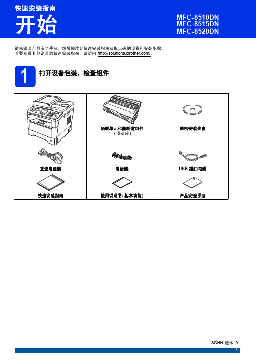
brother MFC-8510DN、MFC-8515DN、MFC-8520DN 快速安装指南
8
9 输入个人信息 (本机标识)
本设备可显示日期和时间。如果设置了本机标识,日 期和时间将打印到您发送的每份传真上。
a 按功能键,然后按数字键 0、 3。 b 使用拨号盘输入您的传真号码 ( 最多 20 个数
字),然后按 OK 键。
03. 本机标识
传真 :_ 输入并按OK 键
c 使用拨号盘输入您的电话号码 ( 最多 20 个数 字),然后按 OK 键。如果电话号码与传真号码 相同,请再次输入同一号码。 03. 本机标识 FAX:XXXXXXXXXXX
出厂振铃次数
振铃:4 次 传真检测:开
振铃:4 次 时间:30 秒
模式 传真自动 传真 / 电话
传真手动 外接应答设备
功能 将对方每个呼叫判断为 传真,并发出传真信 号。 但在振铃次数内可以接 听电话。
将自动判断对方是电话 或传真呼叫。 非传真呼叫时将发出快 速双振铃通知您接听电 话。
设备不判断对方每个呼 叫,仅作为普通电话铃 声,需您接听后处理。
外接应答设备自动应答 每次呼叫。如为语音信 息,则将其存储在 TAD 中; 如为传真信息,则 打印出传真。
使用说明
出厂设置电话振铃 4 次 (0 ~ 10 次可调,请参见使用说明书 ( 基本 功能 ) 中的振铃次数 )。电话振铃 4 次后自动发出传真接收信号;
建议:如果设备上外接了电话机,需要经常接听电话时,可将振 铃次数设置为 4 至 6 次。
2
2 移去设备上的包装材料
d 取出硒鼓单元和墨粉盒组件。
重要事项 切勿插入交流电源线。
a 移去设备上的固定胶带和平板扫描器上的保护 膜。
b 打开多功能纸盒 a,从多功能纸盒支撑板中取 出固定胶带 b,然后合上多功能纸盒。
博世B6512 B5512 B4512 B3512报警主机安装快速入门指南说明书

请在安装报警主机之前安装外壳。
将报警主机和随附硬件安装到外壳内。
安装顺序:(仅限北美使用)到并选择您所在地区,Test MenuNotification TestRevisionsTest Report Walk Test RFBT钱夹发射器RFDL–11三技术被动 红外微波, 35 x 25英尺RFPR–12被动红外,防宠物,40 英尺RFDW–RM 隐蔽式门/窗磁RFDW–SM表面安装门/窗磁RFGB 玻璃破碎探测器RFUN通用发射器,带门/窗磁RFSM无线烟雾探测器RFPR–C12幕帘被动红外,防宠物, 40 x 5英尺RFPB–SB RFPB–TB 单键和双键紧急按钮RFKF–TBS RFKF–FBS双键和四键遥控器ACA–ATR13ACD–ATR14CSACD–ATR11ISOB810 SDI2无线接收机RFRP 无线中继器所有博世IP摄像机DS9370/DS9371360三技术70英尺ISC–BDL2–WP12G/WP6G/W12G三技术40 x 40英尺/20 x 20英尺/40 x 40英尺B430电话(PSTN)D192G 警铃监测模块D125B 双重B类启动模块B201 双线供电循环F220/F220–B6R 烟雾探测器,带底座D132A 反转继电器B56键盘底盒D137安装支架D138安装支架,直角ICP–EZTS 通用防拆B10中型外壳B11小型外壳B208 8输入模块B308 8输出模块ISC–CDL1–W15x 三技术50英尺Commercial 系列B443蜂窝(需要 HSPA+ SIM卡)D5500CU RPS升级远程安全控制移动应用程序B99USB线远程安全控制+移动应用程序G450 Z-Wave 家用控制网关EN4200串行接收机B820 无线接口B942触摸屏报警主机B901门禁模块(仅限B6512)D101锁和钥匙套件ISC–CDL1–WA15x 三技术+防遮挡功能50英尺注意:部分产品和功能只在特定地区提供。
matlab2014b安装教程
matlab2014b安装教程1、下载解压缩,得到iso格式的matlab 2014b文件;2、安装DVDFab Virtual Drive虚拟光驱,并将iso文件装载到虚拟光驱中;3、打开“setup.exe”文件开始安装,选择“不使用internet安装”;4、选择“是”接受许可协议;5、安装密钥随意20个数字,11111111111111111111,就可以;6、安装路径,小编更改为D:\Program Files\MATLAB\R2014b;7、安装的产品,全选;8、快捷方式,全选;9、确定安装;10、正在安装,请稍等一会儿,大概30分钟,看电脑配置而定;11、安装完成,弹出产品配置说明;12、不要勾选“激活matlab”,否则将无法运行,这一步至关重要哟;13、找到虚拟光驱crack目录中的“libmwservices.dll”复制到【D:\Program Files\MATLAB\R2014b\bin\win64】替换同名文件即可成功破解;14、打开软件,用户已经拥有一个无限制完全免费的matlab 2014b破解版本。
matlab 2014b功能介绍一、主要特性用于数值计算、可视化和应用程序开发的高级语言可实现迭代式探查、设计及问题求解的交互式环境用于线性代数、统计、傅立叶分析、筛选、优化、数值积分以及常微分方程求解的数学函数用于数据可视化的内置图形以及用于创建自定义绘图的工具用于改进代码质量和可维护性并最大限度地发挥性能的开发工具用于构建自定义图形界面应用程序的工具可实现基于 MATLAB 的算法与外部应用程序和语言(如 C、Java、.NET 以及Microsoft Excel)集成的函数二、数值计算MATLAB提供了一系列用于分析数据、开发算法和创建模型的数值计算方法。
MATLAB语言包括用以支持常见的工程设计和科学运算的数学函数。
核心的数学函数采用处理器优化库,可以快速地执行向量运算和矩阵运算。
安华b 变频器说明书

南方安华B3000系列变频调速器使用手册V1.2深圳市南方安华电子科技有限公司SHENZHEN NOWFOREVER ELECTRONICS TECHNOLOGY CO.,LTD.目录序 言 (3)开箱检查 (4)1 安全注意事项 (5)1.1 安全事项 (5)1.2 注意事项 (7)2 产品规格及选配件 (10)2.1 产品技术规格 (10)2.2 产品系列介绍 (11)2.2.1 B3000系列变频器型号 (11)2.2.2 B3000系列变频器型号与铭牌说明 (12)2.2.3 B3000系列变频器外形尺寸 (13)2.2.4 防护盖 (15)2.2.5 LED键盘显示单元尺寸 (16)2.3 选配件 (17)2.3.1 制动电阻及制动单元选型推荐动 (17)3 安装及配线 (19)3.1 变频器安装 (19)3.1.1 符合EMC要求的安装方法 (20)3.1.2 噪声抑制 (22)3.1.3 使用浪涌抑制器 (24)3.1.4 漏电流及其对策 (24)3.1.5 使用电源滤波器的场合 (25)3.1.6 使用交流电抗器的场合 (25)3.2 变频器的配线 (26)3.2.1 概述 (27)3.2.2 主回路输入输出端子 (28)3.2.3 控制回路配置及配线 (29)3.2.4 现场配线要求 (40)3.2.5 接地要求 (41)4 变频器运行和操作说明 (42)4.1 运行说明 (42)4.1.1 运行命令通道 (42)4.1.2 频率给定通道 (42)4.1.3 变频器工作状态 (42)4.1.4 变频器运行方式 (43)4.2 操作指南 (43)4.2.1 键盘使用方法 (43)4.2.2 按键功能 (44)4.2.3 指示灯说明 (45)4.2.4 功能码参数的设置方法 (46)4.2.5 速度调节 (47)4.2.6 如何锁定/解锁键盘显示单元 (47)5 详细功能介绍 (49)5.1 基本运行参数(P0组) (49)5.2 电机参数(P1组) (54)5.3 起动制动参数(P2组) (57)5.4 磁通矢量控制参数(P3组) (61)5.5 电流矢量控制参数(P4组) (64)5.6 输入端子控制参数(P5组) (64)5.7 输出端子控制参数(P6组) (75)5.8 过程闭环参数(P7组) (81)5.9 多段参数(P8组) (86)5.10 增强功能参数(P9组) (87)5.11 显示参数(PA组) (102)5.12 通讯参数(PB组) (104)5.13 专用功能参数1(PC组) (105)5.14 专用功能参数2(PD组) (109)5.15 故障保护参数(PL组) (114)5.16 变频器状态(PN组) (119)5.17 参数保护(PP组) (120)5.18 厂家参数(PU组) (121)6 故障对策及异常处理 (122)7 保养和维护 (128)7.1 日常保养及维护 (128)7.2 定期维护 (128)7.3 变频器易损件更换 (129)7.4 变频器的存贮 (130)7.5 变频器的保修 (130)8 功能参数简表 (131)9 通讯协议 (167)通信方式 (167)协议格式 (167)协议功能 (167)几点说明 (177)应用举例 (177)变频器的定标关系 (178)序 言感谢您购买南方安华生产的B3000系列变频器。
德尔塔DOP-B系列触摸屏快速安装指南说明书
Preface Thank you for purchasing DELTA’s DOP-B series. This quick start will be helpful in the installation, wiring and inspection of Delta HMI. Before using the product, please read this quick start to ensure correct use. You should thoroughly understand all safety precautions before proceeding with the installation, wiring and operation. Place this quick start in a safe location for future reference. Please observe the following precautions:⏹Install the product in a clean and dry location free from corrosive and inflammable gases orliquids.⏹Ensure that all wiring instructions and recommendations are followed.⏹Ensure that HMI is correctly connected to a ground. The grounding method must comply withthe electrical standard of the country (Please refer to NFPA 70: National Electrical Code, 2005 Ed.).⏹Do not modify or remove wiring when power is applied to HMI.⏹Do not touch the power supply during operation. Otherwise, it may cause electric shock.⏹For the information of HMI software operation, and software installation, please refer to theHMI software manual.If you have any questions during operation, please contact our local distributors or Delta sales representative.The content of this quick start may be revised without prior notice. Please consult our distributors or download the most updated version at /industrialautomation.Safety PrecautionsCarefully note and observe the following safety precautions when receiving, inspecting, installing, operating, maintaining and troubleshooting. The following words, DANGER, WARNING and STOP are used to mark safety precautions when using the Delta’s HMI product. Failure to observe these precautions may void the warranty!InstallationWiringCall 1(800)985-6929 for SalesOperationD o not modify wiring during operation. Otherwise it may result in electric shockor personal injury.N ever use a hard or pointed object to hit or strike the screen as doing this may damage the screen and let the screen has not respond at all, and then cause HMIto work abnormally.Maintenance and InspectionD o not touch any internal or exposed parts of the HMI as electrical shock mayresult.Do not remove operation panel while power is on. Otherwise electrical shock may result.W ait at least 10 minutes after power has been removed before touching any HMI terminals or performing any wiring and/or inspection as an electrical charge maystill remain in the HMI with hazardous voltages even after power has beenremoved.T urn the power off before changing backup battery and check system settings after finishing change. (all data will be cleared after changing battery).B e sure the ventilation holes are not obstructed during operation. Otherwisemalfunction may result due to bad ventilation or overheating troubles.Wiring MethodCommunication WiringInstallation and Storage ConditionsThe product should be kept in the shipping carton before installation. In order to retain the warranty coverage, the HMI should be stored properly when it is not to be used for an extended period of time. Some storage suggestions are:⏹Store in a clean and dry location free from direct sunlight.⏹Store within an ambient temperature range of -20°C to +60°C (-4°F to 140°F).*********************** Call 1(800)985-6929 for Sales⏹Store within a relative humidity range of 10% to 90% and non-condensing.⏹Do not store the HMI in a place subjected to corrosive gases and liquids.⏹Correctly packaged and placed on a solid and durable surface.⏹Do not mount the HMI adjacent to heat-radiating elements or in direct sunlight.⏹Do not mount the HMI in a location subjected to corrosive gases, liquids, or airborne dust ormetallic particles.⏹Do not mount the HMI in a location where temperatures and humidity will exceedspecification.⏹Do not mount the HMI in a location where vibration and shock will exceed specification.⏹Do not mount the HMI in a location where it will be subjected to high levels ofelectromagnetic radiation.InstallationInstallation Notes⏹Improper installation will result in malfunction and greatly reduce the life of the HMI. Be sureto follow the guidelines in this quick start when installing the HMI.⏹In order to ensure the HMI being well ventilated, make sure that the ventilation holes are notobstructed and must provide sufficient free space around HMI.⏹To ensure the panel is well protected, be sure to install a waterproof gasket into HMI.⏹For use on a flat surface of a Type 4X "Indoor Use Only" enclosure or equivalent.⏹The allowable thickness of the panel for mounting should be less than 5 mm.Installation Method:Step 1:Ensure to put waterproof gasket into HMI and then insert the HMI into the panel cutout. Step 2:Ensure to insert fasteners into the HMI’s insertion slots and turn the screw till screwstouch panel cutout.Step 3:Turn the screw with less than torque 0.7N.M toavoid damage to plastic box.Step 4:Keep at least 60mm distance from rear of HMIproduct to the wall, installation surface or theother controllers for heat dissipation.Call 1(800)985-6929 for Sales*********************** Call 1(800)985-6929 for Sales***********************WiringPlease observe the following wiring notes while performing wiring.Wiring Notes⏹To prevent electric shock, do not change wiring when the power is connected and has not been turned off. ⏹Because there is no power switch on the HMI, ensure that an interrupter switch is attached on its power cable. ⏹ Please use shielded twisted-pair cables for wiring.Recommended wiring is in the table below: Wire Gauge (AWG)Stripped length Torque Solid 28 ~ 127 ~ 8 mm 5 kg-cm (4.3 lb-in) Stranded30 ~ 12 7 ~ 8 mm 5 kg-cm (4.3 lb-in) Be sure to perform wiring by referring to the following figure (power supply connector).Basic InspectionContentGeneral Inspection ⏹ Periodically inspect the screws of the connection between the HMI anddevice. Tighten screws as necessary as they may loosen due to vibrationand varying temperatures.⏹ Ensure that oil, water, metallic particles or any foreign objects do not fall inside the HMI, control panel or ventilation slots and holes. As these willcause damage.⏹ Ensure the correct installation and the control panel. It should be freefrom airborne dust, harmful gases or liquids.Inspection before operation (power is not applied) ⏹ Ensure that all wiring terminals are correctly insulated.⏹ Ensure that all wiring is correct or damage and or malfunction may result.⏹ Visually check to ensure that there are not any unused screws, metalstrips, any conductive or inflammable materials inside HMI.⏹ Ensure to lower electromagnetic interference when devices are influencedby it.⏹ Ensure that the external applied voltage to HMI is correct and matched tothe controller.Inspection before operation (power is applied)⏹ Check if power LED lights.⏹ Check if the communication among devices is normal.⏹ Please contact our local distributors or Delta sales representative if thereare any abnormal conditions. Call 1(800)985-6929 for Sales ***********************Call 1(800)985-6929 for Sales ***********************Pin Definition of Serial CommunicationDOP-B07S(E)415/DOP-B07PS415 / DOP-B08S(E)515 / DOP-B10S(E)615 SeriesCOM1 Port (Supports Flow Control)ContactCOM Port PIN RS-23212 RXD3 TXD45 GND67 RTS8 CTS9 PIN 1Note: Blank = No Connection.COM2 Port (Supports Flow Control)MODE1 MODE2 MODE3 COM PortPIN RS-232 RS-422 RS-485 1 TXD+ D+ 2 RXD 3 TXD 4 RXD+ 5 GND GND GND 6 TXD- D-7 RTS8 CTS9 RXD-PIN1Note1: Blank = No Connection.Note2: When COM2 port is used for RS-232 flow control, i.e. RTS and CTS signals are used for flow control,COM3 port will become incapable of being used.Note3: When COM2 port is used for RS-422 flow control, please refer to the following COM3 Port signalstable for pin assignments. The signals, RTS+, CTS+, RTS- and CTS- shown in brackets are the signals used for flow control. COM3 PortMODE1 MODE2 MODE3 COM PortPIN RS-232 RS-422 RS-485 1 TXD+(RTS+) D+ 2 RXD 3 TXD 4 RXD+(CTS+) 5 GND GND GND 6 TXD-(RTS-) D-789 RXD-(CTS-)PIN1 Note1: Blank = No Connection.Note2: When COM2 port is used for RS-422 flow control, please refer to the COM3 Port signals table abovefor pin assignments. The signals, RTS+, CTS+, RTS- and CTS- shown in brackets are the signals used for flow control.Call 1(800)985-6929 for Sales ***********************Call 1(800)985-6929 for Sales ***********************Ethernet Interface (LAN)Contact Ethernet Interface (LAN)PIN Ethernet 1 TX+ 2 TX-3 RX+456 RX-78 Note: Blank = No Connection.DOP-B05 / DOP-B07S(E)515 / DOP-B07PS515 Series COM1 Port (Supports Flow Control)Contact COM PortPIN RS-232 1 2 RXD 3 TXD45 GND67 RTS8 CTS9 PIN1 Note: Blank = No Connection.COM2 and COM3 PortMODE1 MODE2 MODE3 COM2COM3COM2 COM3COM2COM3COM PortPIN RS-232RS-485RS-485RS-485RS-232RS-4221 D+ TXD+2 RXD RXD 3 TXD TXD 4 D+ D+ RXD+5 GND GND GND 6 D- TXD-789 D- D- RXD-PIN1Note1: Blank = No Connection.Note2: B05 / B07S(E)515/ B07PS515 series models do not support RS-422 flow control function.Call 1(800)985-6929 for Sales ***********************Call 1(800)985-6929 for Sales ***********************Parts NamesDOP-B05S100 / DOP-B05S101 (Front View)BAPower LED Indicator (Lights in green when HMI works normally.) B Touch Screen / DisplayDOP-B05S100 / DOP-B05S101 (Rear View)Call 1(800)985-6929 for Sales ***********************Call 1(800)985-6929 for Sales ***********************AA Power LED Indicator (Lights in green when HMI works normally.)B Touch Screen / DisplayDOP-B07S(E)515 / DOP-B07PS515 (Rear View)A*********************** Call 1(800)985-6929 for SalesC: Power LED IndicatorLights in green when HMI works normally.: Operation LED Indicator (Blue)The operation LED indicator blinks in blue when either the communication is carried out or the data is accessing (please refer to the “Note1” below for explanation).: Alarm LED Indicator (Red)The alarm LED indicator blinks in red when one of the alarms is on.***********************Call 1(800)985-6929 for SalesDOP-B07S(E)415/ DOP-B07PS415 (Rear View)A Power Input TerminalBCOM3(It is provided with two LED indicators to indicate that HMI is in Read or Write status during the communication process.)C COM2(It is provided with two LED indicators to indicate that HMI is in Read or Write status during the communication process.) D COM1 E USB ClientF Ethernet Interface (LAN)G USB HostH Audio Output InterfaceI Memory Card Slot / Battery CoverCall 1(800)985-6929 for Sales ***********************: Power LED IndicatorLights in green when HMI works normally.: Operation LED Indicator (Blue)The operation LED indicator blinks in blue when either the communication is carried out or the data is accessing (please refer to the “Note1” below for explanation).: Alarm LED Indicator (Red)The alarm LED indicator blinks in red when one of the alarms is on.A Power Input TerminalB COM3(It is provided with two LED indicators to indicate that HMI is in Read or Write status during the communication process.)C COM2(It is provided with two LED indicators to indicate that HMI is in Read or Write status during the communication process.)D COM1E USB ClientF Ethernet Interface (LAN)G USB HostH Audio Output InterfaceI Memory Card Slot / Battery Cover: Power LED IndicatorLights in green when HMI works normally.: Operation LED Indicator (Blue)The operation LED indicator blinks in blue when either the communication is carried out or the data is accessing (please refer to the “Note1” below for explanation).: Alarm LED Indicator (Red)The alarm LED indicator blinks in red when one of the alarms is on.A Power Input TerminalB COM2(It is provided with two LED indicators to indicate that HMI is in Read or Write status during the communication process.)C COM3(It is provided with two LED indicators to indicate that HMI is in Read or Write status during the communication process.)D COM1E USB ClientF Ethernet Interface (LAN)G Memory Card Slot / Battery CoverH USB HostI Audio Output InterfaceJ System KeyPanel Cut-outDOP-B05S100 / DOP-B05S101+1.0+0.04"Note:T=1.6mm(0.063")~Units: mm (inches)DOP-B07S(E)415 / DOP-B07PS415+1.0Note:T=1.6mm(0.063")~6mm(0.24")+0.04"Units: mm (inches)Call 1(800)985-6929 for Sales ***********************Note:T=1.6mm(0.063")~+0.04"Units: mm (inches)DOP-B08S(E)515Units: mm (inches)Note:T=1.6mm(0.063")~6mm(0.24")+1.0+0.04"Units: mm (inches)SpecificationsDisplay Type 5.6” TFT LCD (65536 colors) 7” Widescreen TFT LCD(65536 colors)Resolution 320 x 234 pixels800 x 480 pixelsBacklight LED Back Light (less than 20,000 hours half-life at 25C) (Note 1)L C D M O D U L EDisplay Size 113.28 x 84.70mm152.4 x 91.44mmOperation System Delta Real Time OS MCU32-bit RISC Micro-controllerNOR Flash ROMFlash ROM 4 MB(OS System: 2MB / User Application: 2MB)Flash ROM 8MB(OS System: 2MB / User Application: 6MB)Flash ROM 128 MB (OS System: 30MB / Backup: 16MB / UserApplication: 82MB) SDRAM 8Mbytes16Mbytes64Mbytes Backup Memory 128Kbytes16MbytesBuzzer Multi-Tone Frequency (2K ~ 4K Hz )/85dBSound EffectOutput AUXN/AN/AN/AStereo output N/AIEEE 802.3, IEEE802.3uEthernet InterfaceN/AN/AN/A10/100 Mbps auto-sensing (has built-in isolated power circuit (Note3)) N/A Memory CardN/AN/ASD Card (supports SDHC)USB 1 USB Host (Note 2)Ver 1.1 / 1 USBSlave Ver 1.11 USB Host (Note 2) Ver 2.0 / 1 USB Slave Ver 1.1COM1RS-232 (supports hardware flow control)COM2RS-232/RS-485RS-232/RS-422/RS-485 RS-232/RS-422/RS-485 (has built-in isolated power circuit (Note 3))RS-232/RS-422/RS-485Serial COM PortCOM3 RS-422/RS-485RS-232/RS-422/RS-485 RS-232/RS-422/RS-485(has built-inisolated powercircuit (Note 3))RS-232/RS-422/RS-485 Function Key N/A Perpetual Calendar (RTC)Built-inCooling Method Natural air circulation Safety Approval CE /UL (Note 4) /KCC (Note 4)Waterproof DegreeIP65/NEMA4Operation Voltage (Note 5) DC +24V (-10% ~ +15%)(please use isolated power supply) DC +24V (-10% ~+15%)(please use isolated powersupply) DC +24V (-10% ~+15%) (has built-in isolated power circuit (Note 3))DC +24V (-10% ~ +15%)(please use isolated powersupply)Voltage Endurance AC500V for 1 minute (between charging (DC24V terminal) and FG terminals)Power Consumption(Note 5)3.0W5W7.5W5WBackup Battery 3V lithium battery CR2032 x 1Backup BatteryLife It depends on the temperature used and the conditions of usage,about 3 years or more at 25C.Operation Temp. 0o C ~ 50oC Storage Temp. -20o C ~ +60oCAmbient Humidity 10% ~ 90% RH [0 ~ 40C], 10% ~ 55% RH [41 ~ 50C]Pollution Degree 2 Vibration Resistance IEC 61131-2 Compliant5Hz ≦f <9Hz = Continuous: 1.75mm / Occasional: 3.5mm 9Hz ≦f ≦150Hz = Continuous: 0.5g / Occasional: 1.0gX, Y, Z directions for 10 timesDimensions (W) x (H) x (D)mm184 x 144 x 50 215 x 161 x 50 Panel Cutout (W) x (H) mm172.4 x 132.4 196.9 x 142.9 WeightApprox.670gApprox.970gdriving current is supplied to HMI. The life of LED backlight shown here is an estimated value under 25C normal temperature and humidity conditions. 2) USB Host port can provide up to 5V/ 500mA of power.3) The withstand voltage of the isolated power circuit is 1500V peak for 1 minute.4) Some models are in the process of application to UL and KCC certification. For more information, please consult our distributors.5)The value of the power consumption indicates the electrical power consumed by HMI only without connecting to any peripheral devices. In order to ensure the normal operation, it is recommended to use a power supply which the capacity is 1.5 ~2 times the value of the power consumption.6) Users can download the DOPSoft software, the program editor of Delta HMI product and the user manual via the following link: /industrialautomation/.7) The content of this quick start may be revised without prior notice. Please consult our distributors or download the most updated version at /industrialautomation/.Display Type 7” TFT LCD (65536 colors) 8” TFT LCD (65536 colors) 10.1” Widescreen TFT LCD(65536 colors)Resolution 800 x 600 pixels800 x 600 pixels1024 x 600 pixelsBacklight LED Back Light (less than 10,000 hours half-life at 25C) (Note 1) L C D M O D U L EDisplay Size 141 x 105.75mm162 x 121.5mm 226 x 128.7mmOperation System Delta Real Time OS MCU 32-bit RISC Micro-controllerNOR Flash ROMFlash ROM 128 MB(OS System: 30MB / Backup: 16MB / User Application: 82MB)SDRAM 64Mbytes Backup Memory 16MbytesBuzzer Multi-Tone Frequency (2K ~ 4K Hz )/85dBSound EffectOutput AUXN/AStereo output N/AN/AStereo output N/AStereo output IEEE 802.3, IEEE 802.3u IEEE 802.3, IEEE 802.3u IEEE 802.3, IEEE 802.3u Ethernet InterfaceN/A 10/100 Mbps auto-sensin g (has built-in isolated power circuit (Note 3))N/A N/A 10/100 Mbps auto-sensing(has built-in isolated power circuit (Note 3))N/A10/100 Mbps auto-sensing (has built-in isolated power circuit (Note 3))Memory CardSD Card (supports SDHC)USB 1 USB Host (Note 2) Ver 2.0 / 1 USB Slave Ver 1.1 COM1RS-232 (supports hardware flow control)COM2RS-232/RS-485 RS-232 / RS-485(has built-in isolated powercircuit (Note 3))RS-232/RS-485RS-232/RS-422/RS-485RS-232 / RS-422 / RS-485 (has built-in isolated power circuit(Note 3)) RS-232/RS-422/RS-485RS-232 / RS-422 / RS-485 (has built-in isolated power circuit(Note 3)) Serial COM PortCOM3RS-422/RS-485 RS-422 / RS-485(has built-in isolated power circuit (Note 3))RS-422/RS-485RS-232/RS-422/RS-485RS-232 / RS-422 / RS-485 (has built-in isolated power circuit(Note 3))RS-232/RS-422/RS-485RS-232 / RS-422 / RS-485 (has built-in isolated power circuit(Note 3))Function Key N/A Perpetual Calendar (RTC) Built-inSafety Approval CE /UL (Note 4) /KCC (Note 4)Waterproof DegreeIP65/NEMA4OperationVoltage (Note 5)DC +24V (-10% ~ +15%) (please use isolated power supply) DC +24V (-10% ~ +15%) (has built-in isolated power circuit (Note 3))DC +24V (-10% ~ +15%) (pleaseuseisolatedpower supply)DC +24V (-10% ~ +15%) (please use isolated power supply) DC +24V (-10% ~ +15%) (has built-in isolated power circuit (Note 3)) DC +24V (-10% ~ +15%) (has built-in isolated power circuit (Note 3)) Voltage Endurance AC500V for 1 minute (between charging (DC24V terminal) and FG terminals)Power Consumption(Note 5)7.68W5.2W7.8W12WBackup Battery 3V lithium battery CR2032 x 1Backup BatteryLife It depends on the temperature used and the conditions of usage, about 3 years or more at25C.Operation Temp. 0o C ~ 50oC Storage Temp. -20o C ~ +60oCAmbient Humidity 10% ~ 90% RH [0 ~ 40C], 10% ~ 55% RH [41 ~ 50C]Pollution Degree 2 Vibration Resistance IEC 61131-2 Compliant5Hz ≦f <9Hz = Continuous: 1.75mm / Occasional: 3.5mm 9Hz ≦f ≦150Hz = Continuous: 0.5g / Occasional: 1.0gX, Y, Z directions for 10 times Dimensions (W) x (H) x (D)mm184 x 144 x 50 227.1 x 174.1 x 61 272 x 200 x 61 Panel Cutout (W) x (H) mm172.4 x 132.4 219.4 X 166.5 261.3 X 189.3 WeightApprox.800gApprox.1226gApprox.1520gdriving current is supplied to HMI. The life of LED backlight shown here is an estimated value under 25C normal temperature and humidity conditions. 2) USB Host port can provide up to 5V/ 500mA of power.3) The withstand voltage of the isolated power circuit is 1500V peak for 1 minute.4) Some models are in the process of application to UL and KCC certification. For more information, please consult our distributors.5)The value of the power consumption indicates the electrical power consumed by HMI only without connecting to any peripheral devices. In order to ensure the normal operation, it is recommended to use a power supply which the capacity is 1.5 ~2 times the value of the power consumption.6) Users can download the DOPSoft software, the program editor of Delta HMI product and the user manual via the following link: /industrialautomation/.7)The content of this quick start may be revised without prior notice. Please consult our distributors or download the most updated version at /industrialautomation/.Önsöz DELTA’nın DOP-B serisi operatör panellerini seçtiğiniz için teşekkürler. Bu bilgi dökümanı Delta HMI kurulum, bağlantı, bakım ve kontrolünde kullanıcıya yardımcı olacaktır. Doğru kullanım için ürünü kullanmadan önce bu dökümanı mutlaka okuyunuz. Kurulum, bağlantı ve çalışma yapmadan öncegüvenlik uyarılarını tamamen anladığınızdan emin olunuz. Bu dökümanı daha sonra da kullanmak için iyi muhafaza ediniz. Lütfen aşağıdaki güvenlik uyarılarına dikkat ediniz:⏹Ürünün kurulumunu yanıcı gaz ve sıvılardan uzak kuru ve temiz ortamlara yapınız.⏹Bağlantıları yaparken tüm bağlantı kurallarının sağlandığından emin olunuz.⏹HMI’nın toprak bağlantısının doğru yapıldığından emin olunuz. Topraklama metodunun ürününkurulduğu ülke standartlarına uygun olduğuna emin olunuz (NFPA 70: National Electrical Code, 2005 Ed.).⏹HMI enerjili iken kablo bağlantısı yapmayınız ya da sökmeyiniz.⏹Çalışma sırasında power supply terminallerine dokunmayınız. Aksi halde elektrik şoku olabilir.⏹HMI yazılımının kurulumu, çalışması ve donanım bağlantısı ile ilgili daha fazla bilgi için lütfenHMI manualini inceleyiniz.Ürünün kullanımı ile ilgili sorularınız için, lütfen teknik servisimizle bağlantıya geçiniz.Herhangi bir ihbara gerek kalmaksızın bu bilgi dökümanının içeriği değiştirilebilir. Güncellenmişversiyonu elde etmek için teknik servise danışabilir veya /industrialautomation adresinden indirebilirsiniz.Güvenlik UyarılarıÜrünü alırken, kontrol ederken, kurulumunu yaparken, çalıştırırken, bakım ve arıza teşhisi yaparkenaşağıdaki güvenlik uyarılarına dikkat ediniz. DANGER, WARNING, ve STOP başlıkları DELTA HMIürününü kullanırken yapılması gerekenleri dikkat çekmek için kullanılmıştır. Ürünün garantisini muhafaza etmek için bu uyarılara mutlaka dikkat ediniz!KurulumBağlantıÇalışmaÇalışma sırasında kablo bağlantılarını değiştirmeyiniz. Aksi halde elektrik şokuna veya kişisel zararlara sebep olabilir.D okunmatik ekrana sert ve sivri nesneler kullanarak basmayınız. Aksi halde HMI ekranızarar görebilir, komutlara cevap veremeyebilir ve HMI’nın anormal çalışmasına sebepolabilir.Bakım ve KontrollerH MI içindeki devre elemanlarına dokunmayınız aksi halde elektrik şoku meydana gelebilir.Enerjili iken operatör paneli bağlantılarına müdahale etmeyiniz. Aksi halde elektrik şoku meydana gelebilir.H MI enerjisi kesildikten sonra HMI üzerinde tehlikeli seviyede elektrik şarj voltajıkalabileceğinden ürüne dokunmadan ve bağlantılara müdahale etmeden önce en az 10dakika beklenilmesi tavsiye edilir.P ili değiştirmeden önce ürünün enerjisini kesiniz ve pili değiştirdikten sonra sistem ayarlarını kontrol ediniz. (Pil değiştirildikten sonra tüm datalar silinecektir).Çalışma sırasında havalandırma deliklerinin tıkalı olmadığından emin olunuz. Aksi halde kötü havalandırmadan veya aşırı sıcaklıktan dolayı ürün zarar görebilir.Bağlantı MetoduHaberleşme BağlantısıKurulum ve Saklama KoşullarıKurulum yapılana kadar ürün orjinal kutusu içinde muhafaza edilmelidir. Ürünün garanti kapsamının devamı için, ürün belli bir süre kullanılmayacaksa, HMI uygun bir şekilde saklanmalıdır. Bazı saklama önerileri:⏹Doğrudan güneşışığının temas etmediği kuru ve temiz ortamda saklanmalıdır.⏹-20°C - +60°C (-4°F - 140°F) sıcaklık aralığında saklanmalıdır.⏹10% - 90% rutubet aralığında ve yoğunlaşmasız ortamda saklanmalıdır.⏹HMI aşındırıcı sıvı ve gaz bulunan ortamlarda saklanmamalıdır.⏹Ürün uygun paketlenmeli, sert ve düz bir yüzeyde saklanmalıdır.⏹HMI aşındırıcı gaz ve sıvının olduğu toz veya metal parçacıkların bulunduğu yerlere monteedilmemelidir.⏹HMI dokümanda belirtilen sıcaklık ve rutubet oranları dışında ortamlara monte edilmemelidir.⏹HMI dokümanda belirtilen titreşim ve şok oranlarının üzerindeki ortamlara monte edilmemelidir.⏹HMI yüksek seviyede elektromanyetik radyasyonun bulunduğu ortamlara monte edilmemelidir.KurulumKurulum Notları⏹Yanlış kurulum yapılması ürünün zarar görmesini veya çalışma ömrünün kısalmasına sebepolur. HMI kurulumunun doküman da belirtildiği gibi yapılması gerekir.⏹HMI’nın havalandırmasının doğru olduğuna emin olmak için, havalandırma deliklerinin tıkalıolmadığına ve HMI etrafına gerekli boşluğun bırakıldığına emin olunuz.⏹ Panelinkorumasını sağlama almak için, HMI içine su geçirmez conta takınız.⏹Düz yüzey, Tip 4X “Sadece kapalı alanda kullanım” ve eşdeğer ortamlarda kurulum yapılmalıdır.⏹Montaj için kullanılan panelin kalınlığı 5 mm’den az olmalıdır.Kurulum Metodu:Adım 1:HMI içine su geçirmez contanın takıldığına emin olunuz ve sonra pano boşluğuna yerleştiriniz. Adım 2:Montaj aparatlarını HMI’nın yuvalarına yerleştiriniz ve sonra panoya değene kadar vidaları sıkınız.Adım 3:Plastik kasaya zarar vermemek için vidayı0.7N.M’den az bir tork ile sıkınız.Adım 4:Isı dağılımı sağlanabilmesi için HMI arka paneli ileduvar, kurulum yüzeyi veya başka kontrol cihazıarasında en az 60 mm boşluk bırakınız.Call 1(800)985-6929 for Sales***********************Ba ğlant ıBa ğlant ı yaparken a şa ğıdaki ba ğlant ı noktalar ına dikkat ediniz. Ba ğlant ı Notlar ı⏹ Elektrik şokunu önlemek için, enerji varken ba ğlant ı yapmay ın ız.⏹ HMI’n ın power anahtar ı olmad ığı için, besleme kablosuna şalter konuldu ğuna emin olunuz. ⏹ Ba ğlant ı için lütfen çift dolanm ış sarmal (twisted pair) kablo kullan ın ız.Tavsiye edilen ba ğlant ı şekli a şa ğıdad ır :Kablo Kesiti (AWG)Soyulacak uzunlukTorkSolid 28 ~ 12 7 ~ 8 mm 5 kg-cm (4.3 lb-in) Stranded30 ~ 127 ~ 8 mm 5 kg-cm (4.3 lb-in)Lütfen ba ğlant ın ın a şa ğıdaki şekilde gösterildi ği gibi oldu ğuna emin olunuz. (power supply konnektör).Temel KontrolAçıklamaGenel Kontrol⏹ HMI ba ğlant ılar ın ı periyodik olarak kontrol ediniz. Titre şim ve s ıcakl ıkde ği şiminden dolay ı gev şeyen vidalar ı s ık ın ız.⏹ HMI içine, kontrol paneline veya havaland ırma slot ve deliklerine ya ğ, su,metal parçalar veya yabanc ı nesnelerin düşmedi ğine emin olunuz. Bu durum ürüne zarar verir. ⏹ Kurulumu do ğru yapt ığın ıza emin olunuz. Ortamda toz, zararl ı gaz ves ıv ılar olmamal ıd ır . Çal ışmadan önce kontrol (enerji verilmeden önce )⏹ Tüm ba ğlant ı terminallerinin do ğru izole oldu ğundan emin olunuz. ⏹ Zarar ve hasar meydana gelmemesi için tüm ba ğlant ılar ın do ğruyap ıld ığına emin olunuz.⏹ HMI içinde kullan ılmayan vidalar ın, metal parçalar ın, iletken veya yan ıc ımaddelerin olmad ığın ı gözle kontrol ediniz.⏹ Ürünü etkileyebilecek elektromanyetik gürültünün düşük oldu ğuna eminolunuz.⏹ HMI ünitesine uygulanan harici voltaj ın do ğru ve ürüne uygun oldu ğunukontrol ediniz . Çal ışt ırmadan önce kontrol (enerji verildikten sonra )⏹ Power LED ışığın ın yand ığın ı kontrol ediniz. ⏹ Cihazlar aras ında haberle şmenin normal oldu ğunu kontrol ediniz. ⏹ Anormal bir durum ile kar şıla şt ığın ızda teknik servisimizle ba ğlant ıyaCall 1(800)985-6929 for Sales ***********************。
博世B6512 B5512 B4512 B351控制面板快速安装指南说明书
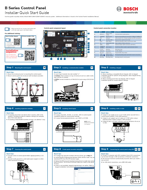
Mounting the control panelMount the enclosure prior to mounting the control panel.Mount control panel into enclosure with hardware provided.Installation sequence:keypad installation instructions.(North America only)1. Scan QR code.3. Locate and select your region for additional videos.Test MenuNotification TestRevisionsTest Report Walk Test RFBT Billtrap Transmitter RFDL–11PIR Microwave TriTech 35 x 25 ft. RFPR–12 PIR, Pet Immune 40 ft.RFDW–RMRecessed Door/Window ContactRFDW–SM Surface Mount Door/Window Contact RFGB Glass Break DetectorRFUN Universal Transmitter w/ Door/Window ContactRFSM Wireless Smoke DetectorRFPR–C12Curtain PIR,Pet Immune 40 x 5 ft. RFPB–SB RFPB–TB 1 & 2 ButtonPanicRFKF–TBS RFKF–FBS 2 & 4 Button KeyfobsACA–ATR13ACD–ATR14CSACD–ATR11ISOB810 SDI2 Wireless Receiver RFRP Wireless RepeaterAny Bosch IP cameraDS9370/DS9371360TriTech 70 ft.ISC–BDL2–WP12G/WP6G/W12G TriTech 40 X 40 ft./20 x 20ft./ 40 x 40 ft.B430 Telephone (PSTN)D192G Bell Super Vision ModuleD125BDual Class BInitiating Module B201 2–wire powered loopF220/F220–B6R Smoke Detector plus BaseD132AReversing RelayB56 Keypad Backbox D137 Mounting BracketD138 Mounting Bracket Right AngleICP–EZTS Universal TamperB10 Medium EnclosureB11 Small EnclosureB208 Octo-Input ModuleB308 Octo-Output ModuleISC–CDL1–W15x TriTech 50 ft.Commercial SeriesB443 Cellular (HSPA+ SIM Required)D5500CU RPS Upgrade Remote Security Control Mobile AppB99 USB Cable Remote Security Plus Mobile AppG450 Z-WaveHome Control GatewayEN4200Serial ReceiverB820Wireless InterfaceB942WTouch ScreenControl panel B901 Access Module (B6512 only)D101 Lock and Key setISC–CDL1–WA15x TriTech+ w/Anti-Mask 50 ft.Note: Not all products and features are available in all regions. Consult your Bosch representative or product datasheets for details.*Home automation may not be available in all regions. Consult your Bosch representative for details.-A versions of RADION devices are used in North and South America. Non -A versions are used in Europe, Africa, and Australia.B442 Cellular (GPRS SIM Required)B444 Cellular (Verizon LTE, hot SIM Required)B520 AUX Power Supply*CX4010 18 VACTransformer*TR1850 18 VACTransformerD121818Ah BatteryD135A Low-Battery Disconnect ModuleD1267Ah BatteryPowerCommunicatorsRADION wireless devicesKeypadsB940WTouch ScreenB920 Text w/ Function KeysB930 Text w/ Soft Keys B915 TextB921CCapacitive Touch RFID tags (for Readers & B942 Keypads)Inovonics wireless devicesPrograming and softwareIP camera integrationEnclosures & accessoriesResidential fireAccess modulesI/O expansion modules*Home automationWired motion detectorsBlue Line Gen2 SeriesClassic Series*DE-45-1818 VAC Transformer *Country specific, variants will apply(Not in all regions)(Not in all regions)(Not in all regions)(Not in all regions)(Not in all regions)B450 Remote Cellular Interface(Not in all regions)(Not in all regions)(Not in all regions)(Not in all regions)(Not in all regions)Installer Services Portal(Not in all regions). Program your Click the 3 vertical dots and select © Bosch Security Systems B.V., 2019 Modifications reserved F.01U.324.620 | 04 | 2019.09B942Touch ScreenB444-V Cellular (Verizon LTE) B444-A Cellular (AT&T LTE)(Not in all regions)Bosch Security Systems B.V.Torenallee 495617 BA Eindhoven NetherlandsB915I Text。
Visual-Basic-6.0安装步骤
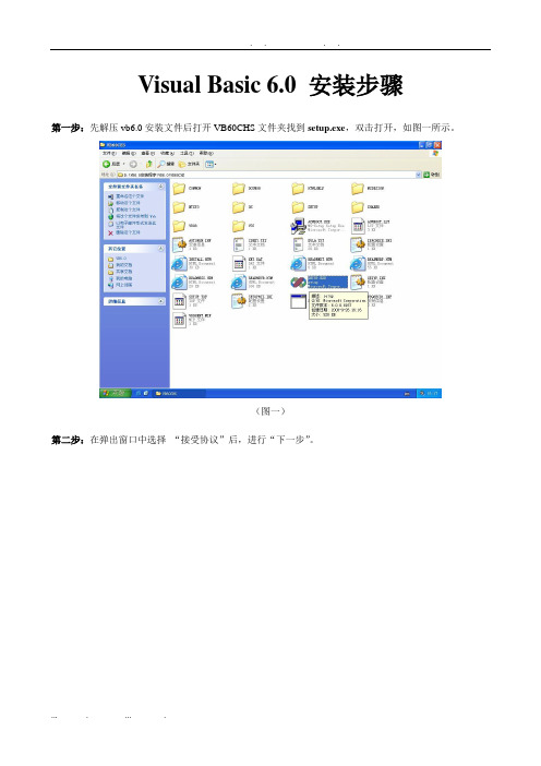
注意:
1.在安装完sp5更新包后,某些系统会提示重新启动windows,选择重启后,即可完成全部安装
2.安装完毕后打开VB6.0,点击工具栏中的“帮助(H)”,在下拉菜单中选择“关于Microsoft Visual Basic(A)”,如下图所示
3.在弹出窗口中发现红框所标注字样,以及在序列号红线处中未出现“*”字样,即为完整安装完毕。
Visual Basic 6.0SP5更新包安装步骤
第一步:打开VB6 sp5文件夹,找到setupsp5.exe,双击执行
(图一)
第二步:在弹出窗口中选择“继续”
(图二)
第三步:在弹出窗口中选择“接受”,然后程序会自行安装
(图三)
第四步:安装完毕后,在弹出窗口中点击“确定”即可完成整个VB6.0的安装。
第十步:重启后出现“安装MSDN”窗口,把勾去掉,然后点击“下一步”,如图十红框标注位置
(图十)
第十一步:在“现在注册“窗口中不打勾,点击“完成”。如图十一红框标注位置
(图十一)
注意:
1.第六、第七步一定按步骤做,不然会导致某些VB功能不可用(此2步十分重要)
2.第五步可能在某些操作系统中不出现,可跳过,亦可选择“是”,推荐选择“否”
Visual Basic 6.0安装步骤
第一步:先解压vb6.0安装文件后打开VB60CHS文件夹找到setup.exe,双击打开,如图一所示。
(图一)
第二步:在弹出窗口中选择“接受协议”后,进行“下一步”。
(图二)
第三步:在输入ID窗口中都输入1,然后下一步。
(图三)
第四步:选择“安装visual basic6中文企业版”,然后下一步。在弹出窗口中点击“继续”。
brother DCOP-145C DCP-165C DCP-185C 快速安装
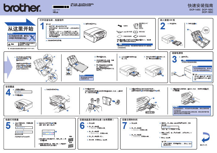
安装 Reallusion 公司支持的可选应用程序
13
您可使用 FaceFilter Studio 编辑照片数据并添 加照片效果,例如去除红眼或增强肤色。
重要事项
• 计算机必须连接到因特网上。 • 设备必须打开并连接到计算机。 • 确保您以管理员身份登陆。
a. 弹出并重新插入随机
光盘或从根目录中双 击start.exe程序再次 打开主菜单。
安装墨盒
4
a. 液晶显示屏显示: 无墨盒
b. 打开墨盒盖a。
1
c. 移去绿色保护部件a。
1
d. 打开墨盒的包装。
顺时针旋转黄色保护盖上的绿色旋钮直至其卡入到位,以解开封 条,然后移除保护盖a。
e. 将墨盒按照标签上箭头指示的方向装入。
注意锁定释放杆a的颜色是否与墨盒颜色b匹配。
1 2
1
f. 将墨盒轻轻地向前推动,直至卡入到位。 安装完所有墨盒后,
LX0712020
CHN 中国印刷
使用设备前,请仔细阅读此快速安装指 南以便获取正确的安装步骤和说明。
快速安装指南
DCP-145C DCP-165C DCP-185C
从这里开始
重要事项
初次安装驱动软件前,请勿将 USB接口电缆连接到设备上。
警告
此图标警告您应如何避免可 能造成的人身伤害。
本快速安装指南的图例均基于 DCP-145C。
c. 小心地将 USB 接口电缆嵌入槽内,然后从 重要事项
d. 抬起扫描器盖板,松开锁定杆
设备后部拉出。 将 USB 接口电缆连接到您 的计算机。
• 请勿将本设备连接到无电
a。轻轻按下扫描器盖
板支撑杆b,然后
1
源的 USB 集线器上。直接
USB 3.0 数据连接和 KM 切换器电缆快速安装指南说明书
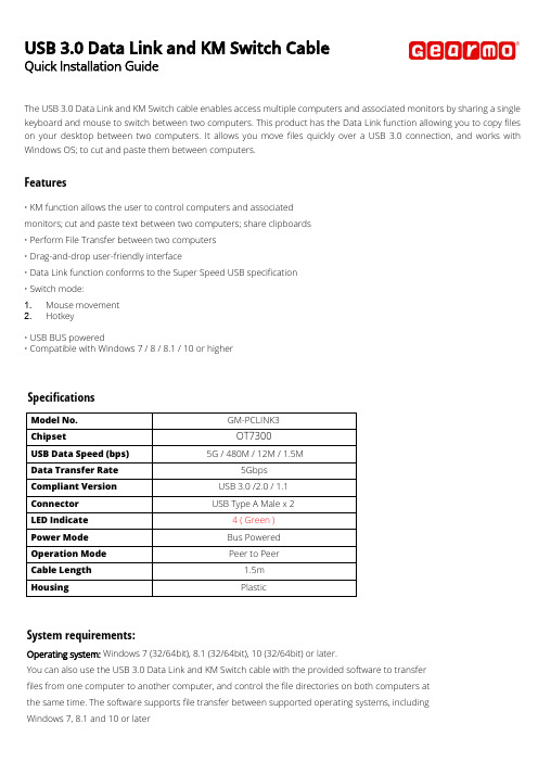
USB 3.0 Data Link and KM Switch CableQuick Installation GuideThe USB 3.0 Data Link and KM Switch cable enables access multiple computers and associated monitors by sharing a single keyboard and mouse to switch between two computers. This product has the Data Link function allowing you to copy files on your desktop between two computers. I t allows you move files quickly over a USB 3.0connection, and works with Windows OS; to cut and paste them between computers.Features•KM function allows the user to control computers and associate dmonitors;c ut and paste text between two computers; share clipboards•Perform File Transfer between two computers•Drag-and-drop user-friendly interface•Data Link function conforms to the Super S peed USB specification•Switch mode:1.M ouse movement2.Hotkey•USB BUS powered•Compatible with Windows 7 / 8 / 8.1 / 10 or higherSpecificationsModel No. GM-PCLINK3Chipset OT7300USB Data Speed (bps) 5G / 480M / 12M / 1.5MData Transfer Rate 5GbpsCompliant Version USB 3.0 /2.0 / 1.1Connector USB Type A Male x 2LED Indicate 4 ( Green )Power Mode Bus PoweredOperation Mode Peer to PeerCable Length 1.5mHousing PlasticSystem requirements:Operating system: Windows 7 (32/64bit), 8.1 (32/64bit), 10 (32/64bit) or later.You can also use the USB 3.0 Data Link and KM Switch cable with the provided software to transferfiles from one computer to another computer, and control the file directories on both computers atthe same time. The software supports file transfer between supported operating systems, includingWindows 7, 8.1 and 10 or laterInstallationStarting Windows1.Connect one end of the USB 3.0 Data Link and KM Switch cable to a standard USB port on one of the two computers.And connect the other end of the USB 3.0 Data Link and KM Switch cable to a USB port on the second computer.2.The device will automatically start the Smart KM Link software installation on both computers.3.An option window may appear. Please click on the executive archive “SmartDataLink.exe”Troubleshooting:If auto-run is not launched, please follow the steps:a.Check both computers are properly connected to the USB 3.0 Data Link and KM Switch cable.b.Go to My Computer and double-click the SMARTLINK icon (F:) to start the application. (In this case, SMARTLINK is seton drive F:)4.If the “User Account Control” window appears on the screen, Click “Yes” to continue.Click [Install] to continue…5. When the USB 3.0 Data Link and KM Switch cable is connected properly the [Oti U3 Transfer Cable] will be shown under Transfer Cable Class in the Windows Device Manager.Congratulation! You have successfully installed the USB 3.0 Data Link and KM Switch cable.Application Software InstructionsTo begin set up, please click USB3Smart Data Link Utility Icon found in bottom right corner of taskbar.Note:If there is one end connected to a USB 2.0 port of the 2 computers, the link icon will show as below figure. That means the operation is working on USB 2.0 specification.If there is one end failed to link, the SmartDataLink icon appears bottom right corner of taskbar will mark with an [x]To retrieve link connection, you may remove & plug in both ends of the USB 3.0 Data Link and KM Switch cable. Or go to My Computer and double-click the SMARTLINK icon (F:) and then click the executive archive “SmartDataLink.exe”.and select PreferencesSetupMove the mouse cursor to bottom right corner of taskbar, right click the SmartDataLinkicon for further settings. 1. KM Sharinga.Select [Turn Off] to disable the Keyboard and Mouse Control Switching Settings b.Use Mouse to Move Off the Edge of Screen:c.Select [Use mouse move off the edge of screen] to simply move the mouse off the edge of screen.d.Use Mouse Middle Button:e.Click the middle button of the mouse to switch the keyboard and mouse from one computer toanother.Hotkeya.You can setup the hotkey to activate the keyboard control switching.b.The default hotkey is (Alt+S)c.Move the mouse cursor to the second computer and open any editing application such as Word, Excel, Power Point,etc. and use the keyboard of the first computer to type the text on the file of the second computer.Note:1-1. P lease use a Mouse and Keyboard set. The Keyboard Switch function always follows the mouse cursor of the samecomputer. When using a USB Mouse or Keyboard that is not a set, it will default to its limitedscreen switching function mode only.1-2. When the keyboard & mouse is under controlled by other computer, you will see the icon on the bottomright corner of the taskbar.2. Clipboard sharinga.Open a file and select the content (text/pictures) you want from the first computer, right click and select “Copy”.b.Move the cursor to the location of the 2nd computer to place the Content (text/pictures), and right click and select“Paste”*When receiving clipboard data from another computer, the SmartDataLink icon appears at the bottom right corner of the taskbar.c.Select [ T urn Off] to disable the Clipboard Share Optionsd.Select [Auto Share] to activate Clipboard sharing between 2 computers automatically.Event NotificationYou may Activate/Disable [Play sound] & [Popup a Balloon Tip] according to the menu selections such as a clipboard data is arriving; or to Activate/Disable [Popup a Balloon Tip] when a clipboard data is sending.Activate/Disable [Play Sound] when switch keyboard and mouse control to another computer.3. File transferringDrag & DropIt is an easy and fast way to transfer files between two computers. Just “drag and drop” the file or folder to theother computer.You can also do the following to transfer files between the two computers.Copy & Paste:a.Right-click on the files that you want to copy and select Copyb.Move the cursor to the other computerc.Move the cursor to the location that you would like to place the file and Right click, then selectPaste Hotkeys (Shortcut on Keyboard) :a.Click on the files that you would like to copy, and press the (Ctrl+C) Keys from Windows OS computerb.Move the cursor to the other computerc.Move the cursor to the location that you would like to place the files, and press the (Ctrl+V) Keys to paste thecopied files to another computer.Note: Please use the original system hotkey settings on your computer operating system (the keyboard always follows the mouse cursor).4. Othersa. b.Select [Resident The Application]: the SmartDataLink will be activated automatically after boot in or restart Windows.When you disable this function or remove the USB 3.0 Data Link and KM Switch cable, the SmartDataLink will be Turned Off automatically.Select [Double Click The System Tray Icon]: double-click the SmartDataLink icon of taskbar, to turn off & disable clipboard sharing & KM sharing temporarily. Double-click the icon again to turn on the SmartDataLink function.If you have driver install questions or need software instructions, contact your distributor for further support.WEEE (Waste of Electrical and Electronic Equipment),Recycling of Electronic ProductsRegulatory ComplianceDisclaimer Information in this document is subject to change without notice. The manufacturer does not make any representations or warranties (implied or otherwise) regarding the accuracy and completeness of this document and shall in no event be liable for any loss of profit or any other commercial damage, including but not limited to special, incidental, consequential, or other damages. No part of this document may be reproduced or transmitted in any form by any means, electronic or mechanical, including photocopying, recording or information recording and retrieval systems without the express written permission of the manufacturer.All brand names and product names used in this document are trademarks, or registered trademarks of their respective holders.CE Certification This equipment complies with the requirements relating to electromagnetic compatibility. It has been manufactured under the scope of RoHS compliance.FCC Compliance StatementThis equipment generates and uses radio frequency and may cause interference to radio and television reception if not installed and used properly. This equipment has been tested and found to comply with the limits of a Class B digital device, pursuant to part 15 of the FCC Rules. These limits are designed to provide reasonable protection against harmful interference in a residential installation. You are cautioned that changes or modification not expressly approved by the party responsible for compliance could void your authority to operate the equipment. This device complies with part 15 of the FCC Rules. Operation is subject to the following two conditions:(1)This device may not cause harmful interference, and (2)This device must accept any interference received, including interference that may cause undesired operation In 2006 the European Union introduced regulations (WEEE) for the collection and recycling of all waste electrical and electronic equipment. It is no longer allowable to simply throw away electrical and electronic equipment. Instead, these products must enter the recycling process. Each individual EU member state has implemented the WEEE regulations into national law in slightly different ways. Please follow your national law when you want to dispose or any electrical or electronic products. More details can be obtainedfrom your national WEEE recycling agency.。
brother hl-b2050dn hl-b2000d hl-2595dw 安全手册 说明书
HL-B2050DN/ HL-B2000D/ HL-2595DW/ DCP-B7500D/ DCP-7090DW/DCP-L2535DW/ DCP-B7520DW/ DCP-B7530DN/ DCP-7190DW/DCP-L2550DW/ DCP-B7535DW/ DCP-7195DW/ MFC-B7700D/ MFC-B7720DN/MFC-7895DW兄弟工业株式会社日本名古屋市瑞穗区苗代町 15 番 1 号 邮编:467-8561尝试操作本产品或执行任何维修前,请仔细阅读这本手册。
未能遵循其中的说明可能会增加火灾、触电、烧伤或窒息发生的概率,造成人身伤害或财产受损。
对于因用户未遵循本手册中的说明而导致的任何损坏,Brother 概不承担任何责任。
如何使用本手册:1.使用设备前,请先通读整本手册。
请妥善保管好本手册,以便日后查阅。
2.请认真遵循本手册中的说明,并始终确保遵循产品上标注的所有警告事项与说明进行操作。
3.如果阅读本手册后对产品使用方法仍有疑虑,请联系 Brother 呼叫中心或您当地的 Brother 经销商。
4.为确保您能理解所有说明,请仔细阅读本手册中使用的符号和惯例。
5.注意:使用本产品前,请仔细阅读这些说明,以确保正确操作。
提示如需了解更多信息和产品规格,请访问以下网站阅读高级说明书:目录本手册中使用的符号和惯例 (3)编辑及出版说明 (3)选择安放产品的位置 (4)安全连接产品 (7)安全使用产品 (8)重要安全说明 (15)产品保修和责任 (16)商标 (19)开放源代码许可备注 (20)版权与许可 (20)关于复印的法律限制 (仅限带扫描功能的产品) (20)本手册中使用的符号和惯例本手册中使用的符号和惯例如下。
请遵循本产品上标注的所有警告事项和说明进行操作。
警告警告图标表示可能导致死亡或重伤的潜在危险情况。
注意注意图标表示可能导致轻微或中度伤害的潜在危险情况。
重要事项重要事项图标表示可能导致财产损失或产品损坏的潜在危险。
BB系统安装步骤

1. 硬件CPU的跳线及连接设置
ControlWave I/O Expansion Rack hardware
4. For the configuration activities, described in this manual, we will use Serial Communication Port 2 (COM2) on the the I/O Expansion Rack, which is configured by default for 9600 baud.
10. Install the Bezel so that it covers the PSSM and CPU Modules
1. 硬件CPU的跳线及连接设置
7. Open the Bezel door, and apply power to the ControlWave controller by setting the Power Switch on the PSSM Module to the ‘1’ position. When the ControlWave completes its power-on sequence, the code "00" should appear on the Port 80 display. The "00" code indicates the ControlWave does NOT have any application program loaded.
1. 硬件CPU的跳线及连接设置
ControlWave I/O Expansion Rack hardware
3. Remove the CPU Module from its carton and install it into Chassis slot 2, i.e., the second slot from the left end of the installed unit. CPU Module DIP Switches may be configured before or after the module has been installed into the Chassis.
华擎B150M-PIO主板快速安装指南说明书

93�体中文�简体中文B150M-PIO1.2 规格平台•uDTX 规格支持 PIO 和 Micro ATX•稳固的电容器设计CPU•支持第 6 代 Intel® Core TM i7/i5/i3/Pentium®/Celeron® 处理器(Socket 1151)•支持高達95W的CPU•Digi Power design•5电源相设计•支持 Intel® Turbo Boost 2.0 技术芯片集•Intel® B150•支持 Intel® Small Business Advantage 4.0内存•双通道 DDR4 内存技术•2 x DDR4 DIMM槽•支持 DDR4 2133 非 ECC,非缓冲内存 (非 ECC 模式下操作)•支持系统内存最大容量:32GB•支持 Intel® Extreme Memory Profile (XMP) 2.0•DIMM插槽中15μ金触点扩充槽• 1 x 直角型PCI Express 3.0 x16插槽(PCIE1:x16 模式)** 支持 NVMe SSD 用作启动盘•1 x 完全尺寸 Mini-PCI Express 插槽:适用于 mPCIe 和mSATA 设备图形•只有 GPU 集成的处理器才支持 Intel® HD Graphics 内置视效和 VGA 输出。
•支持 Intel® HD Graphics 内置视效: Intel® 快速同步视频,采用 AVC、MVC (S3D) 和 MPEG-2 Full HW Encode1、Intel®InTru TM 3D、Intel® Clear Video HD 技术、Intel® Insider TM、Intel® HD Graphics 510/530•Pixel Shader 5.0、DirectX 12•最大共享内存 1792MB•支持 DVI-D,60Hz 时最大分辨率达 1920x1200•支持“加速媒体编解码器”: HEVC, VP8, VP9•通过DVI-D端口支持HDCP•通过DVI-D端口支持全高清1080p Blu-ray (BD)播放94B150M-PIO音频•7.1 CH 高清音频(Realtek ALC887 音频编解码器)*要配置 7.1 CH 高清音频,需要使用高清前面板模块和通过音频驱动程序启用多通道音频功能。
华为TD-BBU安装实用手册
机柜前
c 在定位点打孔并安装膨胀螺栓
•为防止打孔时粉尘进入人体呼吸道和眼睛,操作人员 应采取适当的防护措施。 •打孔深度应该在52mm~60mm之间,且各孔位深度相 同。 •分解膨胀螺栓后,膨胀管的上端面必须与水泥地面相 平,不能凸出水泥地面。
d 将机柜放置于安装孔位并安装
水泥地面
螺栓 M12×60
拆卸UELP单板
设置UELP单板拨码BP530-APM30
将拆卸下来的单板恢复原位
d GPS避雷器外观 e 安装GPS避雷器
•GPS避雷器在室外场景APM30中时,安装在APM30内,保 护地线长度不超过30m,避雷器的“GND”端就近连接至机 柜的接地点上。
•GPS避雷器安装在室内场景中时,安装在馈窗口内侧的走 线架上,距馈窗口1m范围内,保护地线的长度不超过2m; 避雷器的“GND”端连接至室外的接地排上。
21
安装线缆
a 整体线缆图
安装E1线缆时 总体效果图
保护地线 DCDU-03C输入电源线 DBBP530输入电源线 风扇电源线 E1线 Ir光纤 外部告警线
GPS时钟信号线 DCDU-03C保护地线 直流RRU输入电源线 风扇告警线 DCDU-03C告警线
为了防止“GPS时钟信号线”引雷导致E1接口的损 坏, “GPS时钟信号线”和“E1线”走线必须间隔 30mm以上,同时适用于“天馈线”和“信号线”、 “电源线”和“信号线”、“接地线”和“信号线” 之间的间隔要求。
DBBP530 V004R001
快速安装指南
文档版本:03 部件编码:31504774 发布日期:2009-11-05
HUAWEI TECHNOLOGIES Co., Ltd.
目录
一、安装工具
BDCOM S2026B以太网交换机硬件安装手册
BDCOM S2026B以太网交换机硬件安装手册目录目录第1章 BDCOM S2026B简介 (1)1.1 标准配置时的外形说明 (1)1.2 交换机系统特性参数 (2)1.3 ROHS说明 (4)第2章安装准备 (5)2.1 使用注意事项 (5)2.2 安全建议 (5)2.2.1 根据以下原则确保安全 (5)2.2.2 安全警告 (5)2.2.3 带电操作安全原则 (6)2.2.4 预防静电放电损坏 (6)2.3 一般场所要求 (7)2.3.1 场所环境 (7)2.3.2 场所配置预防 (7)2.3.3 机架配置 (7)2.3.4 电源考虑 (8)2.4 安装工具和设备 (8)第3章安装S2026B交换机 (9)3.1 S2026B的安装流程 (9)3.2 交换机机箱安装 (9)3.2.1 安装机箱于桌面 (9)3.2.2 安装机箱于机架 (10)3.3 连接接口 (10)3.3.1 连接监控口 (10)3.3.2 连接快速以太网接口 (12)3.4 扩展以太网接口插卡模块 (14)3.5 安装后检查 (14)第4章交换机维护 (16)4.1 打开机箱 (16)4.2 关闭机箱 (16)第5章硬件故障分析 (18)5.1 故障隔离 (18)5.1.1 电源和冷却系统故障 (18)5.1.2 端口、电缆和连接故障 (18)5.2 指示灯说明 (18)第1章 BDCOM S2026B简介本节主要对BDCOM S2026B交换机总体方面的特性、参数作了说明和介绍,让读者对BDCOM S2026B交换机有一个总体的认识。
本公司每款交换机都有直流电源和交流电源两种,BDCOM S2026B-DC是使用直流电源的S2026B交换机。
1.1 标准配置时的外形说明BDCOM S2026B交交换机交换机标配端口由两个部分组成:24个快速以太网端口,1个Console端口,详细说明如下表。
表 1-1 标配端口特性表端口名称特点快速以太网端口 速率10/100M 自适应,线缆MDI/MDIX自识别,UTP (RJ45)接口,带LINK/ACT、100Mbps指示灯Console端口 速率9600bps,RJ45接口此外,在S2026B交交换机的前端还预留了两个以太网扩展插槽,后端提供了一个接地柱、一个电源插座。
一、快速安装指南
一、快速安装指南1.桌面上放置软垫,将速拍仪放置在软垫的示意位置,并掀起拍摄翻盖至水平 2.启动电脑后,将 USB 电缆方头的一端插到速拍仪底座上,电缆另一端的扁头插到电脑的 USB 端口上,电脑接口必须是高速 USB 2.0。
3.将速拍仪安装光盘放入电脑光驱,电脑会自动执行安装程序。
请根据屏幕上的提示和实际需求进行安装。
4.双击桌面上的速拍仪图标,启动速拍仪软件进行拍摄。
二、电脑系统需求Pentium 4 1.6 CPU 或更高,512 MB 以上内存,200 MB 硬盘空间,USB2.0 接口。
Windows XP-SP2 / Vista/Seven 操作系统(简体中文、繁体中文,英文)。
三、《速拍仪》软件介绍及基本使用方法1.启动:双击桌面上的速拍仪图标,启动《速拍仪》软件。
2.设置 1:选择拍摄界面,根据实际需求设置拍摄参数。
通常只设置,文件类型:BMP、JPG 等图片文件格式;颜色格式:彩色、灰度、黑白,并指定拍摄图像的保存位置。
3.设置 2:通常勾选“自动曝光”和“自动裁切纠偏”,这样可以很方便的拍摄各种题材和幅面的文档。
文档从最大幅面直至名片大小,即使没有摆正、没有放在视野中心,只要完全放置在拍摄视野内,按下“拍摄”按钮后都可以拍摄出没有黑边、不歪斜的图像。
为保证裁切准确,适当调整速拍仪底座位置,使速拍仪视野内只有深色(或稿垫背面黑色)的稿垫,不要让速拍仪“看”到稿垫的边缘、桌子的边缘。
4.连拍:大量快速拍摄时还可选择“连拍”,只要文档放置稳定后,速拍仪就自动拍摄一张,只需更换文档不用再次按钮操作,快捷方便。
5.光照:速拍仪安放位置应选择在光照均匀、拍摄视野内没有光斑、阴影的位置,如果拍摄的文档中有反光(特别是光亮的和反光的文档),请适当调整速拍仪或文档的位置,避开反光。
照明不足时可以按动速拍仪底座上的开关开启速拍仪的照明灯。
四、拍摄界面介绍【浏览】点击该按钮可以指定拍摄图像文件的存储位置。
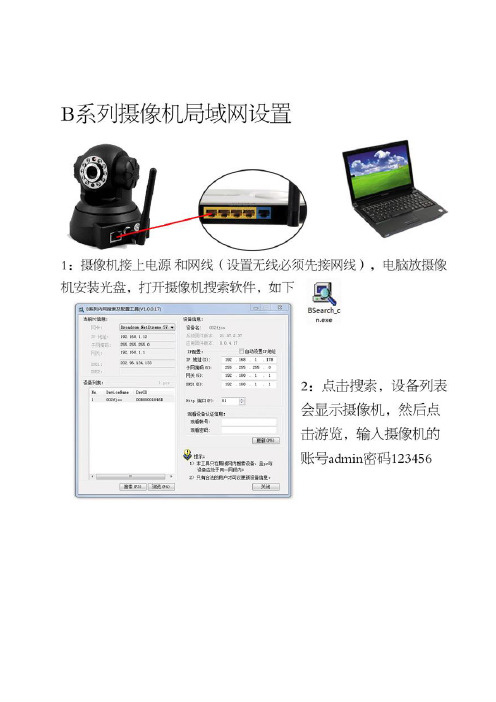
B系列快速安装指南
手机监控方法:手机访问分别为两种方式:手机游览器访问和使用软件方式:1:一般手机都支持javascript 如诺基亚,索爱,三星,摩托罗拉,HCT,IPHONE等。
能实现用网页游览器来访问网络摄像机的动态画面。
首先手机开通上网功能,使用手机自带的游览器或opera游览器(UC,QQ游览器等不支持)输入摄像机的域名如: 输入账号密码即可浏览到画面。
2:专用的软件来游览摄像机的画面,本款摄像机配有专用的软件,如果安卓系统,黑莓系统,JA V A程序。
软件安装和详细的设置方法可以查看光盘里面的手机访问文档。
IPHONE/IPAD 的软件可以到app里面下载越狱的可以到91里面下载,软件名称是live cams 。
3:必须摄像机设置好远程后才可以支持手机监控。
常见问题解答问:为什么使用搜索软件找不到摄像机?答:1,检查摄像机和查找器的电脑是否一个局域网内。
2:,网线或电源问题导致可能(检查电源背部指示灯,换网线试试)3,关闭电脑杀毒软件防火墙等。
问:为什么点击搜索软件浏览打开无法显示?答:1:查看搜索软件当前PC信息和设备信息的IP是否一个网段内。
如PC信息是192.168.0.103 网关是192.169.0.1 设备信息是192.168.1.178 网关是192.168.1.1.这样是不同网段的。
必须改摄像机的IP为192.168.0.178 网关192.168.0.1 输入账号admin密码123456 更新后就可以打开。
问:设置好路由器端口映射后远程还是无法打开摄像机的域名?答:1,检查设置对应摄像机的IP和端口是否正确,摄像机的端口不能用80.2 ,摄像机所接的路由器是否一级路由器,如果是多层路由器需要一级设置端口映射。
3,安装的宽带是否公网IP地址。
问:为什么网络摄像机画面很白或很暗,模糊不清晰或看不到画面?答:1:打开摄像机页面,调试控制面板里面的分辨率和对比度,如果是户外请选择室外模式。
- 1、下载文档前请自行甄别文档内容的完整性,平台不提供额外的编辑、内容补充、找答案等附加服务。
- 2、"仅部分预览"的文档,不可在线预览部分如存在完整性等问题,可反馈申请退款(可完整预览的文档不适用该条件!)。
- 3、如文档侵犯您的权益,请联系客服反馈,我们会尽快为您处理(人工客服工作时间:9:00-18:30)。
手机监控方法:
手机访问分别为两种方式:手机游览器访问和使用软件方式:
1:一般手机都支持javascript 如诺基亚,索爱,三星,摩托罗拉,HCT,IPHONE等。
能实现用网页游览器来访问网络摄像机的动态画面。
首先手机开通上网功能,使用手机自带的游览器或opera游览器(UC,QQ游览器等不支持)输入摄像机的域名如:输入账号密码即可浏览到画面。
2:专用的软件来游览摄像机的画面,本款摄像机配有专用的软件,如果安卓系统,黑莓系统,JAVA程序。
软件安装和详细的设置方法可以查看光盘里面的手机访问文档。
IPHONE/IPAD 的软件可以到app里面下载越狱的可以到 91里面下载,软件名称是live cams 。
3:必须摄像机设置好远程后才可以支持手机监控。
常见问题解答
问:为什么使用搜索软件找不到摄像机?
答:1,检查摄像机和查找器的电脑是否一个局域网内。
2:,网线或电源问题导致可能(检查电源背部指示灯,换网线试试)
3,关闭电脑杀毒软件防火墙等。
问:为什么点击搜索软件浏览打开无法显示?
答:1:查看搜索软件当前PC信息和设备信息的IP是否一个网段内。
如PC信息是网关是设备信息是网关是.这样是不同网段的。
必须改摄像机的IP为网关输入账号admin密码123456 更新后就可以打开。
问:设置好路由器端口映射后远程还是无法打开摄像机的域名?
答:1,检查设置对应摄像机的IP和端口是否正确,摄像机的端口不能用80.
2 ,摄像机所接的路由器是否一级路由器,如果是多层路由器需要一级设置端口映射。
3,安装的宽带是否公网IP地址。
问:为什么网络摄像机画面很白或很暗,模糊不清晰或看不到画面?
答:1:打开摄像机页面,调试控制面板里面的分辨率和对比度,如果是户外请选择室外模式。
拧摄像机前面的镜头可以对焦,达到最佳的效果。
2:看不到画面下载插件安装即可。
问:多个摄像机怎么设置?
答:摄像机默认IP地址都是相同的,必须用搜索软件改摄像机的IP,才可以同时使用,如摄像机A的IP是端口81 另外B摄像机就必须改端口82 由此类推。
问:摄像机密码忘记了怎么办?
答:找到摄像机上面RESET按钮,带电下长按20秒。
恢复出厂后默认账号AAAadmin密码123456
摄像机更多的功能请查看光盘里面的使用手册。
