以太网数据采集板
NET0816-LabVIEW
NET0816以太网数据采集卡应用文档首先感谢您选用CPUBBS论坛()的数据采集卡产品!愿与您携手共建美好明天!以太网采集卡的优势:1),跨平台,在任意可以上网的操作系统上均可以使用;2),不需要独立安装驱动程序,只需要计算机带有网卡并且能上网即可,采集卡无需驱动程序;3),开发平台不受限制,只要能支持TCP/IP的开发平台即可;4),其他接口都受限于接口个数,而以太网则可以通过将每个板子的IP设成不同即可实现组网成一个大系统,并且通过硬件触发功能实现同步采集(NET0816具有外部触发采集功能);5),无论是直连的网线还是交叉的网线,我们的采集卡均能自动识别,并将自动将信号翻转到能连接的状态;6),我们的NET0816已集成一个加密狗,用户可以使用它来保护自己的劳动成果,就算有其他人拿了您的应用程序,以及向我们购买了采集卡,如果密码没经过您修改写入,他一样无法正常使用(在您使用了板载的加密狗的情况下),最大程度保护了您的劳动成果,同样也为您节省成本另购一个加密狗;一,参数说明:NET0816是CPUBBS论坛()开发的多功能数据采集卡;其参数如下:1,配置有2个DIO(均可以配置成DI,DO,其中DIO1还可以配置成外部触发采集功能【此功能可以应用在大系统中,全部采集卡的IO并在一块,然后靠一个外部脉冲触发实现全部板卡同步开始采集】,DIO2可以配置成计数器功能);(CS,SID,SCLK配置成普通IO用,可以达到5个DIO);2,16位AD转换器;±10V的量程;8路差分输入;3,程控增益有:1,10,100,1000倍;4,可软件触发采集,也可以外部DIO1脉冲触发采集;5,采样率说明:单通道采集的情况下可以达到100K,多通道采集的情况下采样速率跟去抖点数有关系[这个软件中可以配置,设去抖点数为X,通道数为N,则多通道的情况下每通道的采样率为100/(N*X),默认情况下X=2,如果双通道采集,则每个通道的采样率为100/(2*2)=25K];(每年用量超过100套的用户,改动不大的功能前提下,可以向我们要求免费定制,定制门槛极低);二,接线方法:由左到右分别为:CH1~CH16,DIO_1,DIO_2,GND,AGND接线方法为:本采集卡有8路差分输入,CH1和CH9组成差分输入通道1,CH2和CH10组成差分输入通道2,依此类推;(如果用此方法接线会有噪声仍然耦合进去了,请再按上面接法之后,再将CH9~CH16同时再接入到AGND,即可解决)三,驱动程序安装方法:基于以太网,无需驱动程序(只需要计算机有网卡,并且已安装网卡的驱动程序,能上网即可);四,以太网数据采集卡操作流程:NET0816是以服务器的形式存在,用户需要主动去连接它,连接上以后即可发送指令及读取数据,操作相当简单;下面是采集卡的默认网络参数:IP: 192.168.1.20默认网关:192.168.1.1子网掩码:255.255.255.0远程端口:5000默认用户密码:0000000000000000(字符串,16个0,阿拉伯数字,如果用16进制发送即是16字节的0x30);此密码正确的情况下,可以修改新密码,但无法读回来密码,只能进行比较是否正确;特别注意事项:如果同一局域网内想多块卡同时使用,在刚拿到板卡时请每块卡单独插上去更改IP后才能全部再插到路由器上使用,因为出厂默认IP全部相同,同时插上去会IP冲突不能连接的;如果以上数据修改后又忘记了也不要担心,我们的板子具备一个自动恢复功能,操作方法为:将板子断电,用摄子将板子上面的J10的二个脚短接,然后上电,等待几秒后即可恢复默认值(包括密码也会恢复默认值);也可以将J10的跳线帽跳上,恢复默认值后再拔掉(不拔掉每次上电均会恢复默认值一次),J10的跳线帽在板卡背面:上面二个图,左边为平常的状态,右边为恢复默认值的状态;五,配套控制子VI使用说明:用户使用时请将NET1616.llb拷贝到工程目录下面,然后即可方便使用里面的各VI;现在我们来详细说明NET1616.llb内各子VI的使用方法(如果熟悉LabVIEW的朋友也可以通过打开演示程序Main.vi,里面有直接的使用方法,很详细,全部功能VI均使用到了。
基于网络的数据采集板卡研制
・21・
采样;⑤双极性模拟输入,范围土 10 V和±5 V可选; ⑥支持串行和并行输出;⑦低功耗⑺% AD7606模数 转换电路如图3所示。
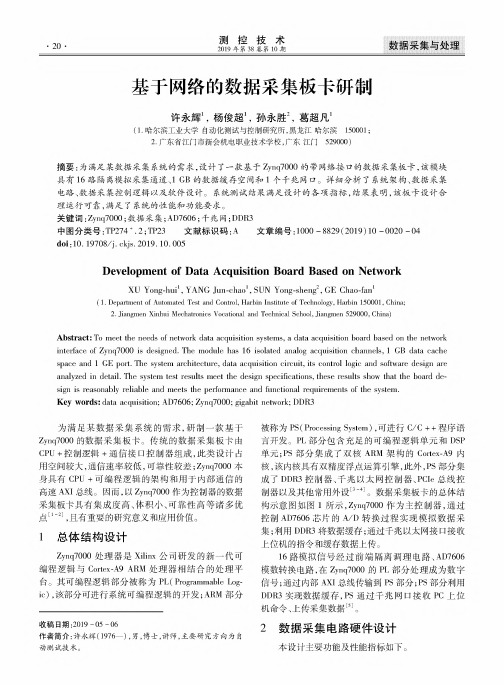
Abstract: To met the needs of netmork date acquisition systems, j date acquisition board based on the netmork interface of Zynq7000 is designed. The moduWe has 16 isolated analoo acquisition channeWs, 1 GB date cache space and 1 GE port. The system architecture, date acquisition circuii, iis ccntrol logic and softearo design art analyzed in detaii. The system isi csuIos met the design specincationSi thesi csuIos show that tie board de sign is reesonablz reliable and meets tUe perfoenanca and functional requirements of the system. Key wordt: data acquisition; AD7606; Zynq7000; gigabit netmork; DDR3
图1总体结构示意图 ① 16通道;
② 总采样率:1600 =S/s; ③ 单通道采样率:100 =S/s; ④ 分辨率:16-bit; ⑤ 输入范围:±36 V; ⑥ 传输速率:>100 Mbits/s; ⑦ 缓存容量:1 GB; ⑧ 连续采样时间上限:300 s; ⑨ 缓存数据上传时间:<60 /% 2.1前端调理电路设计 前端调理电路采用ADI公司的AD215芯片满足 速度和隔离要求。AD215是一种应用广泛的放大器, 以15 V电源供电,具有精度高、功耗低、共模性能好、 成本低的特点。其内部集成了变压器耦合、整流、三阶 滤波等功能,能起到较好的隔离、稳流和滤波作用。在 满足-3 dB带宽的采样要求时,AD215可支持100 =S/s采样率。前端调理电路图如图2所示。
基于PCIe总线的万兆以太网数据采集卡的设计与实现
基于PCIe总线的万兆以太网数据采集卡的设计与实现薛强;汤昊;孟庆磊;高峰;胡迪【摘要】随着以太网接口速率与流量的不断增长,实现对高速网络数据流实时、高效采集是网络安全和流量监控中的重要课题.设计了一块基于PCI Express总线的高速数据采集卡,以Xilinx FPGA芯片为硬件载体,实现了4路万兆以太网数据接入,并使用DMA机制通过PCI Express总线将数据传输到上位机.【期刊名称】《现代电信科技》【年(卷),期】2016(046)002【总页数】6页(P48-53)【关键词】数据采集卡;PCI Express总线;现场可编程逻辑阵列;万兆以太网【作者】薛强;汤昊;孟庆磊;高峰;胡迪【作者单位】中国信息通信研究院泰尔系统实验室,北京100191;中国信息通信研究院泰尔系统实验室,北京100191;中国信息通信研究院泰尔系统实验室,北京100191;中国信息通信研究院泰尔系统实验室,北京100191;中国信息通信研究院泰尔系统实验室,北京100191【正文语种】中文【中图分类】TP393.11论文引用格式:薛强,汤昊,孟庆磊,等.基于PCIe总线的万兆以太网数据采集卡的设计与实现[J].现代电信科技,2016,46(2):48-53.XUE Qiang,TANG Hao,MENG Qinglei,etal.Design and implementationof PCIe-based Gigabit Ethernetbus data acquisition card [J]. Modern Science& Technology of Telecommunications,2016,46(2):48-53.面对移动互联网、高清视频等业务的高速发展,网络带宽压力越发明显,网络容量成为未来业务发展的挑战之一。
电信运营商在从2G/3G分组核心网向4G EPC移动宽带演进过程中,核心网设备接口吞吐量也逐步从1 Gbit/s量级增加到10Gbit/s量级,目前10GE接口已经成为核心网的主流设备接口。
高速以太网通讯数据采集卡使用说明

16 位 64 通道 500KSPS 光隔 AD 16 通道光隔数字入/16 通道光隔数字出T9255 使用说明书一、性能特点:本板采用有线 10M/100M 以太网口的数据采集器。
本采集卡提供基于 DLL 的编程技术,用户不需要网络知识就可以实现网络采集与控制功能。
本板通过采用高速高精度 AD 芯片、高精度的放大器、高密度 FPGA 逻辑芯片、精细地布线以及优良的制版工艺,实现了高速、高精度实时数据采集,具有以下性能特点:1、2、3、4、5、6、64 通道模拟量高速采集。
可以设置 1-64 通道采集,起始通道号可以自由设定。
AD 幅值采集高精度:16 位采集精度,长时间采集时,误差跳码为±2LSB,相对精度优于 0.001%,直流电压波动小于 0.1 毫伏。
软件校准:将校准信息存储在板卡上,用户不用打开仪器设备就可以进行校准,使用方便,一般情况下不需要用户进行任何校准。
丰富的备用扩展资源:板上 CPLD 资源非常丰富,可以为用户的特殊需求进行定制,如旋转编码器接口、脉冲周期测量接口、PWM 输出接口、外同步接口、触发记录接口、开关量控制接口等(定制)。
提供外部时钟模式:在该模式下,外部时钟信号启动所有通道采集一次,从而实现多通道与外时钟同步采集模式(定制)。
提供外部触发启动模式:在该模式下,只有当外部给出上升延触发信号后才开始采集,从而实现用户外触发采集模式的需要(定制)。
二、功能与指标AD 的性能指标:AD 采样精度:16 位AD 通道数:单端方式 64 通道。
AD 采集的综合跳码误差为±2LSB。
模拟采集的定时精度:缺省情况下为 50PPM,特殊要求可以定制AD 输入电压范围:-5V 到+5V、0-10V 可选,或根据用户需要定制量程。
AD 输入阻抗:100 千欧模拟输入安全电压:±15 伏。
当超过 AD 输入量程时,只要不超过安全电压就不会损坏硬件。
建议用户尽可能使输入信号在量程范围内。
数据采集卡

(3)缓存:主要用来存储AD芯片转换后的数据。带缓存板卡可以设置采样频率,否则不可改变。缓存有 RAM和FIFO两种。FIFO主要用作数据缓冲,存储量不大,速度快;RAM一般用于高速采集卡,存储量大,速度较慢。
(4)分辨率:采样数据最低位所代表的模拟量的值,常有12位、14位、16位等。如12位分辨率,当电压量 程为5000mV,单位增量为(5000mV)/4096=1.22mV(注:2的12次方为4096)。
数据采集卡
计算机技术术语
01 分类
03 技术参数
目录
02 功能 04 选型
基本信息
数据采集是指对设备被测的模拟或数字信号,自动采集并送到上位机中进行分析、处理。数据采集卡,即实 现数据采集功能的计算机扩展卡,可以通过USB、PXI、PCI、PCI Express、火线(1394)、PCMCIA、ISA、 Compact Flash、485、232、以太网、各种无线网络等总线接入计算机。
分类
分类
基于PC总线的板卡种类很多,其分类方法也有很多种。 按照板卡处理信号的不同可以分为模拟量输入板卡(A/D卡)、模拟量输出板卡(D/A卡)、开关量输入板 卡、开关量输出板卡、脉冲量输入板卡、多功能板卡等。其中多功能板卡可以集成多个功能,如数字量输入/输出 板卡将模拟量输入和数字量输入/输出集成在同一张卡上。 根据总线的不同,可分为PXI/CPCI板卡和PCI板卡。
采用PoE供电的高速以太网分布式数据采集系统
块 适 用 于 快 速 以太 网应 用 开发 ;传 输部 分 充 分 利 用 了 以 太 网带 宽 大 、结 构 简 单 、可 扩 展 性 强 、成 本 低 廉 的 特 点 ,配合 上 位
机 监 控 软 件 ,可 以方 便 有 效 地 监 管 整 个 系统 。 系统 供 电 采 用 PoE技 术 ,在 传 输 数 据 的 网线 上 同时 提 供 电 流 ,避 免 了 以往
中 图 分 类 号 :TP274
文 献 标 识 码 :A
High-speed Distributed Data Acquisition System Based on PoE
W ang W ei
(M ilitary Representative Bureau of N aval Equipm ent Departm ent in Chongqing A rea,Chongqing 630042,China)
_
:
ll | |j
采 用 PoE供 电 的 高 速 以太 网 分 布 式 数 据 采 集 系统
王 伟
(海 军 装 备 部 驻 重 庆 地 区 军事 代 表 局 ,重 庆 630042)
摘 要 :设 计 了一 种 基 于 以 太 网 的 分 布 式 数 据 采 集控 制 系统 。 该 系统 的 数 据 采 集核 心 采 用 RCM5700微 处理 器模 块 ,该 模
Key words: Ethernet;distributed data acquisition;PoE Fra bibliotek引 言
分 布 式 数 据 采 集 已 经 成 为 了 目前 大 规 模 数 据 采 集 的 优 先 选 择 方 式 。长 期 以来 ,数 据 采 集 常 规 使 用 的集 中 式 采 集 方 式 在 信 号 种 类 繁 多 和 数 量 庞 大 的 大 型 分 布 式 系 统 中 的 应 用 ,极 易 导 致 系 统 连 接 复 杂 、难 以后 期 维 修 保 养 、数 据 中心 设 置 臃 肿 。
兆瓦级风电变流器控制系统的设计
2021.14(1)上海电气技术7兆瓦级风电变流器控制系统的设计杨军亮李春毛琼一上海电气输配电集团技术中心上海200042摘要:介绍了风电变流器控制系统的发展现状,在此基础上设计了兆瓦级风电变流器控制系统。
分析了这一兆瓦级风电变流器控制系统的硬件组成和软件功能。
关键词:风电变流器;控制系统;设计中图分类号:TM46文献标志码:A文章编号:1674-540X(2021)01-007-04Abstract:The development status of control system for the wind power converter was introduced,and the control system for the megawatt wind power converter was designed on this basis.The hardware composition and software functions of this control system for the megawatt wind power converter were analyzed.Keywords:Wind Power Converter;Control System;Design1设计背景随着新能源技术的不断提高,新能源利用效率越来越高,控制系统越来越智能化。
在过去的30多年中,风力发电装机容量持续增长.风力发电机额定容量由50kW提高至7.5MW O基于风电变流器控制系统发展现状,陆地兆瓦级风电变流器主要采用印制电路板控制器.这一控制系统响应速度快、成本低,能够满足陆地风力发电机的控制需求。
但是,印制电路板控制器需要从底层硬件开始设计,开发难度大、周期长。
海上环境较为恶劣,若将印制电路板控制器应用于海上兆瓦级风电变流器,则印制电路板的底层元器件会成为不稳定因素。
海上风电变流器控制系统稳定性和安全性的要求高于陆上风电变流器控制系统,加之海上风力发电机维护成本较高,应尽量减少出海次数,控制系统设计为冗余系统。
通用版-PLC-西门子CP443-1以太网模块

设备驱动任务文档
提出人:()
用户信息:(包括用户单位、用户姓名、联系方式。
如果是销售人员联系而暂无用户信息,列出相关销售人员的联系方式)
用户单位:
联系人:
联系方式:
资料描述:设备一套,说明书一份
需求描述:开发通用版-PLC-西门子CP443-1以太网模块驱动。
开始时间:9月01日
完成时间:9月14日
工作量表:开发160 测试40
测试报告
测试目的:测试驱动程序是否能正确的读取和设定。
基本过程:设计测试工程,定义仪表参数变量,进行变量组态,运行检测。
测试条件:此时与单台下位机连接,要合理的设计测试用例,各类寄存器应选取一些典型有代表性的地址进行测试,以期达到快速、高效的目的。
开始时间:结束时间:
备注:
注意事项:。
ADAM-6217快速入门手册

通过HTML 5连入移动设备
网络
无线访问接入点
连入
通过现场无线AP连 到网络
条形码扫描
扫描设备条形码或 直接访问IP
进入
登录网络服务器 访 问I/O 状态与历史 记录
通过html5连入移动设备网络无线访问接入点连入通过现场无线ap连到网络条形码扫描扫描设备条形码或直接访问ip进入登录网络服务器访问io状态与历史记录具备成组配置功能以设置多个模块adam6200系列模块具有成组配置功能减少重复配置工作在短时间内一次性完成对多个模块的配置
基于以太网的远程数据采集系统的开发

第一章引言1.1课程设计目的本次课程设计的主要目的,是让我们掌握工业生产过程中热工参数等数据采集系统的设计方法和热工过程中诸如温度、压力、流量、液位等参数的测量方法,以及工业以太网、数据采集系统结构、信号的获取、通信、远程数据采集模块及组态软件应用方法。
这次课程设计主要是培养我们独立分析和解决问题的工作能,以及综合运用所学知识进行实际工程设计的基本技能,查阅图书资料、产品手册和各种工具书的能力,工程绘图能力,初步编写技术报告的能力。
1.2课程设计内容本次课程设计的内容是以实验室热工自动化过程控制实验装置(型号:THJDL-1)为研究对象,选用研华公司ADAM-6000系列以太网I/O模块和MCGS组态软件,设计远程数据采集系统,完成实验装置中流量、压力、液位、温度四大热工参数的采集。
最终要达到的目的是通过这套系统,实现热工参数的远程采集。
1.3本人所参与的工作我在这次课程设计中担任的是组长,工作涉及到每一个方面,包括安排组员的任务,协调组员之间的工作内容等。
另外我收集了很多资料、最后的报告撰写我也参与了很大一部分的工作。
在MCGS软件的组态过程中,我与刘柳进行了很多的合作。
在实验室软件组态与接线过程中我也花费了相当多的精力,因为在这里我们遇到的问题是最多的,我们没有专门人员指导,所有的实验步骤都是我们自己摸索的,而且我们的实验老是不成功,软件与硬件不能通讯,我也联系了老师介绍给我们的技术员,但是问题依然没有得到彻底解决。
最后在我们组的共同努力下我们设计的数据采集系统终于采集到了有效的数据。
我也在这次设计过程中学习到了很多的新的有用的知识,在以后的工作中都是相当宝贵的。
第二章热工实验装置简介2.1热工自动化过程控制实验装置2.1.1对象系统的结构及组成“THJDL-1型热工自动化过程控制实验装置”是热工自动化控制实验的对象系统,实验系统的流程如图1 所示。
实验对象系统包含有:不锈钢储水箱;上水箱为有机玻璃圆筒型水箱;下水箱为不锈钢锅炉汽包;三相4.5kW电加热锅炉(由不锈钢锅炉内胆加温筒和封闭式外循环不锈钢冷却锅炉夹套构成)和铝塑盘管组成[1]。
DIO数据采集回放板使用手册

DIO数据采集回放板使用手册1. 产品简介 (1)1.1主要特点 (1)1.2工作模式 (1)1.3主要接口 (2)1.4结构框图 (2)1.5所需设备 (3)1.5.1 硬件设备 (3)1.5.2 软件设备 (5)2. 工作过程 (5)2.1射频板卡频点配置 (5)2.1.1 射频板卡与PC机连接 (5)2.1.2 频点配置程序编译 (7)2.1.3 频点配置程序烧写 (15)2.2DIO数据采集与回放 (20)2.2.1 硬件设备连接 (21)2.2.2 DIO数据采集回放板卡IP设置 (24)2.2.3 DIO数据采集 (28)2.2.4 DIO数据回放 (34)图1-1DIO数据采集回放板卡主要接口 (2)图1-2DIO数据采集回放板整体结构框图 (3)图1-3DIO数据采集回放板卡 (4)图1-4射频板卡 (4)图2-1USB转串口线与射频板卡连接 (6)图2-2射频板卡上连线示意图 (7)图2-3K EIL UVISION3工作界面 (8)图2-4打开频点配置程序所在磁盘 (9)图2-5打开频点配置程序所在文件夹 (10)图2-6打开CONFIG-GPS文件 (11)图2-7打开GPS频点配置程序 (12)图2-8GPS频点配置程序编译通过 (13)图2-9编译前“CONFIG-GPS”文件下的所有文件 (14)图2-10编译后“CONFIG-GPS”文件下的所有文件 (14)图2-11 STC-ISP工作界面 (15)图2-12打开程序文件所在磁盘 (16)图2-13打开程序文件所在文件夹 (17)图2-14打开GPS频点配置程序文件“CONFIG-GPS” (17)图2-15打开“RFC ONFIG.HEX”文件 (18)图2-16下载/编程 (19)图2-17射频板卡上电 (20)图2-18射频板卡与DIO板卡连接 (22)图2-19连接PC机和DIO板卡串口 (22)图2-20DIO板卡千兆以太网口与PC机连接 (23)图2-21连接12V电源适配器 (24)图2-22S ECURE CRT启动界面 (25)图2-23DIO板卡上电后S ECURE CRT界面 (26)图2-24DIO板卡IP设置 (27)图2-25重启DIO板卡 (28)图2-26S YSTEM T EST.EXE界面 (29)图2-27输入DIO板卡的IP地址 (30)图2-28PC机与DIO板卡网络连接正常 (31)图2-29TCP DIO T OOL启动 (32)图2-30通道设置 (32)图2-31采集数据 (33)图2-32TCP DIO T OOL启动 (35)图2-33数据回放 (35)DIO数据采集回放板使用手册1. 产品简介DIO数据采集回放板卡具备多频点卫星中频信号的采集和回放功能。
基于FPGA+ARM的高速图像数据采集板的设计

A R M之 间的数据采集接 口设计 方案,并 实现 了l J i n u x 操作 系统 下F P G A 设备 的中断处理程序 的开发 。并通过设计千兆 以太 网接 口实现 了图像数据的实时远程传 输。
【 关 键 词 】AR M ;F P GA; 千 兆 以 太 网 ;嵌 入 式l i n u x; 中断
1 . 概 述
随 着 图 像 处 理 技 术 的 快 速 发 展 , 图 像 采 集 处 理 系 统在 提 高 工 业 生 产 自动 化 程 度 中 的 应 用 越 来 越 广 泛 。 本 文 结 合 实 际 系 统 中 的 前 端 图像 处 理 和 图 像 数 据 传输 的 需要 ,充分利 用A R M 的灵活性 和F P G A 的 并 行 性 的特 点 , 设 计 了一 种 基 于A R M + F P G A 的 高 速 图像 数 据 采 集 传 输 系 统 。所 选 用 的A R M 体 系结 构 是 3 2 位 嵌 入 式 R I S C 微 处 理 器 结 构 , 该 微 处 理 器 拥 有 丰 富的指令集 且编程灵活 ;而F P G A  ̄ J J 在 速 度 和 并 行 运 算 方 面 有 很 大 优 势 ,适 合 图 像 处 理 的 实 时 性 要 求 ; 并 且 通 过 于 兆 以 太 网 接 口 实 现 了采 集 板 与 上 位 机 之 间 图 像 数 据 的高 速 远程 传 输 。 2 . 硬 件 设 计 方 案 2 . 1系 统 总 体设 计 本 设 计 采 用 的A R M 芯 片 为 三 星 公 司 的 ¥ 3 C 2 4 4 0 A 、F P G A 芯片为X i 1 i n x 公 司 生 产 的S p a r t a n 系 列的¥ 3 C 5 0 0 E 芯 片 , 系 统 组 成 还 包括 千兆 以太 网控 制 芯 片 A X 8 8 1 8 0 、 千 ̄ 6 P H Y 芯片8 8 E 1 1 1 1 、存 储 器 、 嵌 入 式 L i n u x 、 网络 驱 动 程序 等 ( 如图1 所 示) 。 本设计 的主控 芯片¥ 3 C 2 4 4 0 A 是 基 于 A R M 9 2 0 T 核的1 6 / 3 2 位R I S C 微 处理 器 ,采 用 了0 . 1 3 u m 的C M O S 标 准 宏 单 元 和 存 储 器 单 元 ,运 行 频率 高 达5 0 0 M H z 。A P d V I 9 2 0 T 实现 了删 ,A 惦A B U S S U H a r v a r d 高速 缓 冲体 系 结 构 构 。 这 一 结 构 具有 独 立 的 1 6 K B 指 令 C a c h e S g 1 6 K B 数 据C a c h e 。每 个 都 是 由 具有 8 字 长 的行 组 成 。通 过 提供 一套 完 整 的通 用 系统 外 设 ,¥ 3 C 2 4 4 0 A 减 少 整体 系 统 成本 和 无 需配置 额 外 的组 件 。它 主 要面 向手持 设 备 以及 高性 价 比、低 功耗 的应 用 ,具有 非 常丰 富 的 片上 资源 。 F P G A 芯 片s 3 C 5 O O E 主要 用 于 图像传 感器 的控 制 、 图像 数据 的缓存 及 外 围芯 片 时序
DAQBOARD数据采集板系列产品说明书

The DAQBOARD family of data acquisition boards offers more signal conditioning choices than any comparable product, while also providing high-speed performance and low price. These ISA-bus boards offer 10 µsec per-channel, 16-bit measurement capacity over their 16analog input channels and maintain the same performance when expanded up to 256 channels.Moreover, both the boards’ 16 built-in and 256 expansion channels can each be programmed for a different,dynamically selectable gain. This means that a single DAQBOARD can measure various signal types, from thermocouples to strain-gages, while maintaining the 10µsec per-channel rate. Most other data acquisition boards suffer significant speed and performance declines when equipped with expansion channels, because their on-board sequencing supports only built-in channels.The DAQBOARD family’s 256-channel expansion capacity includes low-cost, compact signal conditioning boards for measuring temperature, voltage, and strain, as well as boards for performing isolation, low-pass filtering, and simultaneous sample and hold. These boards can behoused in similarly inexpensive and compact three- or ten-slot enclosures.FLEXIBLE TRIGGERINGThe DAQBOARDs offer an array of both analog and digital triggering capabilities. For example, the units permit you to trigger on the analog input level from any one channel, and also allow you to program the slope and polarity of the trigger level. Because the DAQBOARDS feature ahardware-based trigger, they minimize trigger latency to less than 10 µs. In contrast, most plug-in boards thatemploy software-polling triggers have typical trigger-to-A/D conversion latencies of 100 µs or more. The DAQBOARDs can also be triggered from a TTL-level digital input or from a command from the PC. Pre-trigger data can be collected using any analog channel as the triggering event.ߜ16-bit A/Dߜ100K Reading/sec Real-time Storage-to-Diskߜ8 Differential- or 16 Single-Ended Inputs, Expandable to 256ߜX1, 2, 4, or 8 Programmable Gain (Other Gains Available with Option Cards)ߜExpansion Cards for High Voltage/current,Strain Gage,Thermocouple, Isolation, Filtering and Simultaneous Sample and Holdߜ512-location Scan Memory for User-Defined Channel/Gain SequencingߜAnalog, Digital, or Software Trigger ߜTwo 12-bit Analog Outputs, 100kHz via On-board DMA or FIFOߜ24 General-Purpose Digital I/O Lines,Expandable to 192ߜ16 High-speed Digital-Input Lines,Scannable at up to 100kHz ߜFive Programmable 16-bit Counter/timersData Acquisition Boards For Desktop PCs$1095Basic SystemShown smaller than actual size.The DAQBOARD is no longer available. Please see the OMB-DAQBOARD-2000 as a substitute or contact salesreceived pulses is accumulated, permitting pulse accumulation concurrently with the measurement ofanalog input channels. The units also permit the width of a digital input pulse to be measured on each channel, with resolution to 1 µs.PULSE/FREQUENCY OUTPUTIn pulse/frequency output modes, the DAQBOARD-200’s five counter-timer channels can each be independently programmed to perform one of several functions. In the pulse generation mode, a single pulse of programmable width can be generated from dc to 500 kHz. In the frequency-generation mode, the DAQBOARDs can generate a square wave of duty cycle from 0.0005% to 99%, with frequencies up to 1 MHz.An external timebase can also be input to achieve other frequency outputs. Each of the DAQBOARDs’ counter-timer channels has a one-shot output mode that can generate a pulse output in response to a hardware or software trigger input. The pulse begins at a programmable delay from 1 µs to 655 seconds after receipt of the trigger.SOFTWAREDAQBOARD products support a wide variety of software options, providing you with a diverse selection of software packages in which to develop your data acquisition system.DOS and Windows DriversEvery OMB-DAQBOARD product is supplied with drivers that enable you to develop your own applications under either DOS or Windows. The units’ DOS drivers arecompatible with QuickBASIC, C, and Pascal; the Windows drivers are compatible with Visual Basic, Visual C, and C++. DAQVIEWAll DAQBOARD data acquisition systems includeDAQVIEW, a Microsoft Windows data logging and control application that provides a “no-programming required”interface to all DAQBOARD features.Analog InputDAQVIEW includes an Analog Input window for setting up the unit to acquire data to disk. DAQVIEW’s on-screencontrols let you set parameters such as trigger source, trigger level, and number of scans, and also provides you with a channel-configuration spreadsheet for selecting andassigning labels and gains to each channel. Once you have configured a DAQBOARD and armed it for acquisition, a strip chart window can be opened to display channel data trends in real time. DAQVIEW also enables you to easily access option boards connected to a DAQBOARD. DAQVIEW lets you specify the data format of your output files as binary,ASCII, or both. The ASCII format is compatible with many spreadsheets and graphical analysis programs. You can also use DAQVIEW’s mX+b facility to scale and offset readings on a per-channel basis.Analog OutputDAQVIEW provides an analog output window for interactive control of the DAQBOARD’s’ two D/A converters. Thewindow features a slider and a text entry field for each D/Aconverter, facilitating the setting of output voltage.ANALOG INPUTThe DAQBOARDS’ built-in analog input capability permits them to measure 8 channels in a differential input mode, or 16 channels in a single-ended mode.Their on-board programmable gain instrumentation amplifiers can be dynamically set to x1, 2, 4, or 8.Other gains can be obtained via expansion cards. The DAQBOARDs A/D converter scans selected channels at a constant 10µs/channel rate, minimizing the time skew between consecutive channels. The time between the start of each scan sequence can be programmed to start immediately or at intervals up to 12 hours. The OMB-DBK expansion cards permit each DAQBOARD to be expanded up to 256channels while maintaining its 10µs per channel rate.(For applications that require simultaneous sampling of multiple channels, see OMB-DBK17).ANALOG OUTPUTEach DAQBOARD has two 12-bit D/A converters that allow you to generate voltages of 0 to +5 V. In addition,with a bipolar external reference, output voltages between -10 Vdc and +10 Vdc may be obtained. One D/A converter is internally wired to the analog trigger comparator, and can be software programmed to act as either the trigger-level setting, or the second analog output channel. The DAQBOARDs’ analog outputs can be programmed whenever the DAQBOARDs are not transferring A/D data.HIGH-SPEED DIGITAL INPUTThe DAQBOARD-200 has the ability to scan 16TTL-level digital inputs as part of the user-defined scan sequence. Thus, the units can acquire the state of all 16 high-speed digital input lines within an analog scan sequence. The DAQBOARDs transfer theacquired digital word to the PC within the same data stream as the acquired analog data, eliminating the need for special data handling by the software.GENERAL-PURPOSE DIGITAL I/OThe DAQBOARD-200 includes 24general-purpose digital I/O lines, programmable in 8-bit groups as either inputs or outputs. Digital I/O capacity can be expanded up to 192 lines with the addition of optional expansion cards. The digital I/O lines can beaccessed by the PC whenever the DAQBOARDs are not transferring data from the A/D converter. If an application requires digital inputs with critical timing,the unit’s 16 high-speed digital inputs should be used.FREQUENCY/PULSE INPUTThe DAQBOARD-200 provides five 16-bitcounter/timers, which can be programmed for a wide variety of functions. For frequency measuringapplications, each channel can count frequency inputs up to 7 MHz, with programmable gate time from 1µs to 655 seconds. If expansion beyond the 16-bit capacity of a single channel is required, the units permit channels to be cascaded via software. Also, each channel can be configured for pulse-counting or totalizing applications—wherein the number ofDAQBOARD SeriesD1Digital I/ODaqView includes a digital I/O window that provides you with full interactive control of digital I/O on a DAQBOARD P2 connector and up to four attached option cards. The window allows you to independently configure each port as either an input or output. Counter-Timer WindowDAQVIEW includes a counter-timer window that provides frequency measurement, totalizing, andpulse-train generation applications for the DAQBOARD-200’s five counter-timers.PostViewThis post-acquisition waveform viewing program provides strip-chart recorder-like graphical displays for reviewing large amounts of previously acquired data. Users can display up to 16 channels of data that have been collected and saved to a file by DAQVIEW. Using the program’s intuitive on-screen controls, you can expand, contract, and auto-scale waveforms as well as scroll in either direction.The program also lets you employ the mouse to place markers for extracting time and magnitude data from any point in the waveform. Multiple applications of PostView can be launched simultaneously to view several data files concurrently.EXPANSION, SIGNAL CONDITIONING AND POWER OPTIONSThe DAQBOARDs can be easily expanded beyond their built-in channel capacity via our wide ranging OMB-DBK Series of expansion, signal conditioning, and power supply cards. (See Section H for details and specifications for all OMB-DBK cards.)Analog Input ExpansionAll OMB-DBK Series analog expansion cards are designed to daisy-chain to the P1 analog connector found on all DAQBOARD models.Because the DAQBOARDs feature an on-board channel/gain sequencer, they can directly address up to 256 channels, enabling the scanning of all expansion channels at the same 10µs rate as on-board channels. When equipped with analog input expansion cards, the DAQBOARD must be configured for 16 single-ended inputs. Each 16-channel expansion card in use consumes one of the DAQBOARD’s on-board analog channels; consequently, a maximum of sixteen 16-channel cards can be accommodated, for a total of 256 channels. OMB-DBK Series cards with only 2 or 4 channels can share the same DAQBOARD base channel to maintain the 256 channel maximum.When analog expansion cards are in use, unused DAQBOARD base channels are available to measure input signals. (The OMB-DBK11A screw terminal card provides convenient access to the DAQBOARD base channels.)Data Acquisition Boards for Desktop PCsDAQBOARD SeriesAnalog Input Card HousingYou can house the OMB-DBK analog input expansion cards in a variety of ways. Your choice will depend on the number of cards required by your system.If your application requires six or fewer cards, the slim 3-slotOMB-DBK10 expansion card enclosure is a good choice. The OMB-DBK10 requires anOMB-CA-131-x cable for daisy chaining the analog expansion cards. The OMB-DBK10 enclosures can easily be stacked together.If your application requires more than 6 expansion cards or if you want to allow for future system expansion, the compact 10-slot OMB-DBK41 analog expansion card enclosure isthe preferred solution.Multiple OMB-DBK41s can bedaisy-chained to cost-effectivelyhouse the number of analog inputcards required to bring aDAQBOARD system up to itsmaximum expansion capacity of256 channels. Also, because itfeatures an analog backplane forconnecting the expansion cards,the OMB-DBK41 obviates a longdaisy-chain cable.Powering Analog CardsEvery DAQBOARD model has thecapacity to power several analogexpansion cards. However, if thenumber of cards in yourapplication requires more powerthan can be obtained from thepower supply, the OMB-DBK32Apower supply card is available tomeet your system’s power needs.The OMB-DBK32A attachesdirectly to the P1 analogexpansion bus and supplies powerto all analog expansion cards. TheOMB-DBK32A can be poweredfrom an included ac adapter, orfrom any +10 to +30 Vdc source.When installed in the OMB-DBK10 three-slot expansionenclosure, the OMB-DBK32A isattached via the OMB-CA-131-xcable. If used with the OMB-DBK41 ten-slot expansion cardenclosure, it simply installs intoone of the analog expansionslots on the unit’s backplane.Digital I/O ExpansionThe DAQBOARD-200 featuresa P2connector equipped with 24 digitalI/O channels. You can expandthese models’ digital I/O capacityup to 192 channels via the use ofOMB-DBK series digital I/O cards.These cards can be housed in theOMB-DBK10 three-slot expansionenclosure.(See Section H fordetails and specifications for allOMB-DBK cards.)Connector:DB37 male, P1Resolution: 12-bitsVoltage Ranges:0 to 5 Vdc with built-in reference; 0 up to ±10 Vdc with external referenceMax Output Current:10 mA GENERAL PURPOSE DIGITAL I/O DAQBOARD-200Channels:24 expandable up to 192Depth:512 locationChannel to Channel Rate:10µs/channel, fixedExpansion Channel Sample Rate:same as on-board channels,10µs/channelANALOG OUTPUTS DAQBOARD-200, 216Channels:2Data Acquisition Boards for Desktop PCsDAQBOARD shown with OMB-DBK41expansion enclosure and OMB-DBK cards. (See section H for OMB-DBK specifications)Ordering Example:Qty Description Price 1DAQBOARD-200 16-bitboard with digital I/O$12951 OMB-DBK10 Three slot expansion card enclosure 1953 OMB-DBK81 7-channel thermocouple inputexpansion cards @ 49514851OMB-CA-131-3 Cable from DAQBOARD toOMB-DBK10 65Total Cost:$3040SpecificationsGENERALDAQBOARD-200, 216Power Consumption:200: 1550 mA @ 5 Vdc; 216: 1500mA @ 5 Vdc Operating Temperature:0 to 50°CStorage Temperature:0 to 70°CHumidity:0 to 95% RH, non-condensingA/D SPECIFICATIONS Type:Successive approximationResolution:200, 216: 16-bit Conversion Time:8 µs Linearity:±1 bit16-BIT DAQBOARD-200, 216Channels: 16 single-ended,8differential, expandable up to 256differential; single-ended/differential operation is software programmable Connector: DB37 male, P1Resolution:16-bitsRanges: unipolar/bipolar operation is software programmable on a per-channel basisUnipolar: 0 to 10 V, 0 to 5 V, 0to 2.5 V, 0 to 1.25 VBipolar:0 to ±5 V, 0 to ±2.5 V, 0to ±0.125 V, 0 to ±0.625V Max Overvoltage:30 Vdc Input Impedance:100 M ΩTRIGGERINGDAQBOARD-200, 216Analog TriggerProgrammable Level Range:0to ±5VTrigger to A/D Latency:10 µs max Digital TriggerLogic Level Range:0.8 V low, 2.2 V highTrigger to A/D Latency:10 µs max Software TriggerTrigger to A/D Latency:Dependent on PC speedPre-Trigger: up to 65,536 scans SEQUENCERDAQBOARD-200, 216Randomly programmable forchannel & gain; DAQBOARD-200 is also randomly programmable for unipolar/bipolar ranges and single-ended/differential modesDAQBOARD Series Connector:DB37 male, P2 Device:82C55Output Voltage LevelsMin “1” Voltage:*********sourcingMax “0” Voltage:0.4 @2.5 mA sinkingOutput CurrentMax Source Current: 2.5 mAMax Sink Current:-2.5 mA Input Voltage LevelsMin Required “1” VoltageLevel: 2VMax Allowed “0” VoltageLevel:0.8VOutput Float Leakage Current:10 µAHIGH-SPEED DIGITAL INPUTSDAQBOARD-200Lines:16Connector:DB37 male, P3Max Sampling Rate:100K words/sInput Low Voltage: 0.8 V maxInput High Voltage: 2 V minInput Low Current: 10 nAInput High Current:-10µACOUNTER/TIMERDAQBOARD-200Channels:5Connector: DB37 male, P3Frequency/Pulse CountingMode:up or down, binary or BCDMax Pulse Count:80-bit binary (5channelscascaded)Max Input Rate: 7 MHzMin High Pulse Width: 70 nsMin Low Pulse Width: 70 nsOn-board Time Base: 1 MHzInput Low Voltage: 0.8 V maxInput High Voltage: 2.2 V minInput Low Current: 10 µA maxInput High Current:-10 µA maxFrequency/Pulse GeneratingModeMax Output Frequency: 1 MHzDuty Cycle: variable betweenlimits of approximately 0.0015%and 99.99%Output High Voltage:2.4 V min @ -200µAOutput Low Voltage:***********mAPostView software, and complete operator’s manual. D1 ANALOG INPUT AND MULTI-FUNCTION CARDSMOST POPULAR MODELS HIGHLIGHTEDCANADA www.omega.ca Laval(Quebec) 1-800-TC-OMEGA UNITED KINGDOM www. Manchester, England0800-488-488GERMANY www.omega.deDeckenpfronn, Germany************FRANCE www.omega.fr Guyancourt, France088-466-342BENELUX www.omega.nl Amstelveen, NL 0800-099-33-44UNITED STATES 1-800-TC-OMEGA Stamford, CT.CZECH REPUBLIC www.omegaeng.cz Karviná, Czech Republic596-311-899TemperatureCalibrators, Connectors, General Test and MeasurementInstruments, Glass Bulb Thermometers, Handheld Instruments for Temperature Measurement, Ice Point References,Indicating Labels, Crayons, Cements and Lacquers, Infrared Temperature Measurement Instruments, Recorders Relative Humidity Measurement Instruments, RTD Probes, Elements and Assemblies, Temperature & Process Meters, Timers and Counters, Temperature and Process Controllers and Power Switching Devices, Thermistor Elements, Probes andAssemblies,Thermocouples Thermowells and Head and Well Assemblies, Transmitters, WirePressure, Strain and ForceDisplacement Transducers, Dynamic Measurement Force Sensors, Instrumentation for Pressure and Strain Measurements, Load Cells, Pressure Gauges, PressureReference Section, Pressure Switches, Pressure Transducers, Proximity Transducers, Regulators,Strain Gages, Torque Transducers, ValvespH and ConductivityConductivity Instrumentation, Dissolved OxygenInstrumentation, Environmental Instrumentation, pH Electrodes and Instruments, Water and Soil Analysis InstrumentationHeatersBand Heaters, Cartridge Heaters, Circulation Heaters, Comfort Heaters, Controllers, Meters and SwitchingDevices, Flexible Heaters, General Test and Measurement Instruments, Heater Hook-up Wire, Heating Cable Systems, Immersion Heaters, Process Air and Duct, Heaters, Radiant Heaters, Strip Heaters, Tubular HeatersFlow and LevelAir Velocity Indicators, Doppler Flowmeters, LevelMeasurement, Magnetic Flowmeters, Mass Flowmeters,Pitot Tubes, Pumps, Rotameters, Turbine and Paddle Wheel Flowmeters, Ultrasonic Flowmeters, Valves, Variable Area Flowmeters, Vortex Shedding FlowmetersData AcquisitionAuto-Dialers and Alarm Monitoring Systems, Communication Products and Converters, Data Acquisition and Analysis Software, Data LoggersPlug-in Cards, Signal Conditioners, USB, RS232, RS485 and Parallel Port Data Acquisition Systems, Wireless Transmitters and Receivers。
用VB.NET实现基于以太网的数据采集
s t a b l e a nd r e l i a b l e o p e r a t i o n,a n d i mp r o v e s t h e t e s t a c c u r a c y o f me a s u r e me n t ,a nd a l s o s a v e s t h e t e s t c o s t . Ke y wo r ds: d a t a a c q u i s i t i o n; e t h e r n e t ; VB. NET; W5 1 00 c hi p
EM9636-多功能数据采集、以太网、USB和Wifi接口、脱机离线存储

EM9636-多功能数据采集、以太网、 USB和 Wifi接口、脱 机离线存储
EM9636是一款多功能数据采集模块、具有以太网、USB和无线Wi-Fi接口 EM9636数据采集模块是一款多功能、高性能的数据采集产品。CPU中央处理器采用ARM9核心板,内植入了嵌入式实时操作 系统linux,产品设计选用了新一代高速、高分辫率、高性能集成电路芯片。现场可编程门阵列FPGA的使用,使EM9636数据 采集产品发挥出了强大的功效,可满足多种需求。
★EM9636数据采集模块,具有Web服务器功能。为方便用户使用,EM9636开通了web 服务器功能,主机只要有web浏览 器,就可以对EM9636进行监控,不需要编写任何程序。用户可通过PC 端或手机端的web浏览器设置各项参数、查看状态以 及查看实时数据。手机或移动设备可通过Wi-Fi与EM9636直接通讯。 数据监控:
★免费提供上位机虚拟仪器分析软件。如使用PC机操作EM9636数据采集模块,我公司还可免费提供上位机虚拟仪器分析软 件(基于LabVIEW)。
虚拟仪器软件主要功能 实时波形显示:在采集过程中实时显示数据曲线波形图。 实时数值显示:在采集过程中实时显示所采集数值的结果。 数据存储与回放:对采集的信号进行存储与回放及分析。 显示及打印报表:以曲线或图表的形式打印报表。 图形分析功能:对数据曲线进行缩放、平移、定位(游标)、对比。 ★ EM9636数据采集模块具有多种固定方式。 结构材料:ABS757K阻燃,抗振动:17~500Hz,1G PTP 。 抗冲击:10G/PEAK(11m ,sec)。 工作温度:-20℃~+70℃。 净重:71g。 外壳表面处理:火花纹 产品尺寸:详见技术说明书。 EM9636数据采集模块具有体积小、功耗低、实时信号采集、并可宽温(需定制)使用,支持多种总线、离线脱机采集存储数 据等功能特点,可满足多种需求。网络接口可以将所采集的数据传输到局域网或公网,从而实现全球范围的数据采集与控制。 北京中泰研创科技有限公司
基才SOPC的以太网远程数据采集系统设计
摘 要 : 对测 控 系统 中设备 分散 , 测 环 境 恶 劣 的情 况 , 计 了一 种 基 于 S P 针 检 设 O C的 以 太 网远 程 数 据 采 集 系统 。 系 统采
样 基 于 N o Ⅱ软 核 的 S P 架构 , I / S I 入 式 实 时操 作 系统 为 软 件 运 行 平 台 , L P为 以 太 网通 信 协议 , i s OC 以 x O —I嵌 C 以 WI 实 现 了远 程 数 据 采 集和 以 太 网传 输及 控 制 。 整 个 系统在 C co e P C 5开发 板 上 实现 并 通 过 验 证 , y ln ⅡE 2 3 实验 结 果 满足 设
vaE h r e Srale i sse . ewh l ytm Sraie n e f d o co eⅡE 2 5 d v lp n o r 。 i ten t e zd i t s y tm Th oe sse i e z da dv r e nCy ln i l nh l i i P C3 中 。 往 存 在 现 场 检 测 环 境 恶 劣 . 备 往 设 分 散 , 要 检 测 系 统 具 有 远 程 分 布 式 数 据 采 集 功 能 , 实 现 需 以 设 备 的 远 程 检 测 与 监 控 。 入 式 以 太 网 技 术 将 以 太 网技 术 和 嵌 嵌 人 式 技 术 有 机 结 合 在 一 起 , 好 的 满 足 这 种 需 求 。E e t 很 h t me 与 传 统 通 讯 接 口相 比 , 有 性 价 比高 、 输 距 离 远 、 布 运 行 具 传 分 等 特点 【S P ¨ O C是 基 于 F G : P A解 决 方 案 的 S C 是 MC D P O , U、 S 、 F G 的 有 机 结 合 . 有 体 积 小 、 耗 低 、 灵 活 配 置 等 优 PA 具 功 可 点 [3 2 1 用 S P 以太 网技 术 将 S P 嵌 入 式 测 量 模 块 接 入 -。利 OC OC 网 络进 行 控 制 .使 其 实 现 P C机 所 具 有 的远 近 程 测 量 控 制 和 信 息 发 布 各 项 功 能 . 工 作 人 员 远 离 现 场 . 可 以 对 测 量 设 让 仍 备进行控制 并获得测量数据 。
ADAQ1002数据采集板使用说明书
ADAQ1002数据采集板使用说明书苏州迅芯微电子有限公司目录ADAQ1002 (1)数据采集板使用说明书 (1)目录 (2)声明 (3)阅前必读 (4)1产品简介 (5)2技术指标 (6)2.1接口说明: (6)2.2系统功耗与尺寸 (6)2.3外形尺寸 (7)2.4环境相关 (7)2.5产品包装 (7)2.6安装指导 (7)3产品布局和简要说明 (8)3.1板卡布局图 (8)3.2操作说明 (9)声明苏州迅芯微电子有限公司保留对其产品进行修正、改进和完善的权利,同时也保留在不做任何通告的情况下,终止其任何一款产品的供应和服务的权利。
用户应在下单前向苏州迅芯微电子有限公司获取相关信息的最新版本,并确认该信息是完整且最新的。
阅前必读简介本文是基于Kintex7系列FPGA芯片和AAD06S032G高速模数转换芯片的数据采集模块的硬件说明书,本说明书详细描述了ADAQ002数据采集卡的性能及使用方法。
保修所有由苏州迅芯微电子有限公司生产制造的硬件和软件产品,保修期为从发货之日起一年。
在保修期内由于产品质量原因引起的损坏,由苏州迅芯微电子有限公司提供免费维修或更换。
保修期内的软件升级,同样由苏州迅芯微电子有限公司免费提供。
警告标识本板卡包含ESD敏感器件,请采取必要的防护措施。
使用时请不要用手或非绝缘的物体接触板卡。
因使用不当造成的板卡损坏,本公司只提供付费的维修。
更多信息,请浏览以下网址:或通过该网站的相关信息联系销售人员。
1产品简介ADAQ002数据采集卡通过采样率30G的超高速数字采样ADC和FPGA算法处理,实现实时数据采集功能。
采集卡主要的处理器为Xilinx Kintex®-7480TFPGA,用于实现算法等功能,板卡的模数转换器(ADC)为32GSps 6bit ADC,芯片型号为AAD06S032G。
采集卡的算法处理结果可以通过串口上传至上位机,采集卡具备网口和串口等多种接口。
温度采集板的功能主治
温度采集板的功能主治1. 简介温度采集板是一种用于测量和记录环境温度的设备。
它通常由一个专用的电路板和相应的软件组成,可广泛应用于各种领域,如工业自动化、气象监测、生物医药等。
本文将介绍温度采集板的主要功能和应用领域。
2. 功能特点•温度测量:温度采集板能够实时测量环境温度,并将数据传输给相关的设备或系统。
•数据存储:采集板具备储存温度数据的功能,可以保存一定时间段内的温度变化记录。
•数据传输:采集板支持多种数据传输方式,如串口、以太网、无线等,方便将温度数据传输到不同的设备或系统中。
•精度控制:采集板具备高精度的温度传感器和精密的测量电路,能够提供准确的温度数据。
•报警功能:当温度超出设定的阈值范围时,采集板可以发出警报信号,以便及时采取相应措施。
•远程管理:采集板可以通过远程管理接口进行监控和管理,方便用户远程配置和控制。
3. 应用领域3.1 工业自动化温度采集板在工业自动化中扮演着重要的角色。
它可以用于监测和控制各种设备和设施的温度,确保工业生产过程的安全和稳定性。
例如,温度采集板可以用于监测机器设备的温度,当温度超出安全范围时,及时发出警报并采取相应措施,以防止设备过热或损坏。
3.2 气象监测温度采集板在气象监测领域也有着广泛的应用。
它可以用于测量和记录气象站点的温度变化,为气象科学研究和天气预测提供重要数据。
同时,温度采集板可以与其他气象设备集成,共同完成对气象要素的综合监测和分析。
3.3 生物医药在生物医药领域,温度采集板常用于药品贮存和运输过程中的温度监测。
它可以追踪和记录药品的温度变化,以保证药品的质量和安全。
此外,温度采集板还可以应用于实验室试验中,对生物样本和仪器设备的温度进行监控,确保实验的准确性和可靠性。
3.4 其他领域除了以上提到的领域,温度采集板还可以应用于环保监测、农业科学、食品加工等多个领域。
例如,在环保监测中,温度采集板可以用于监测水体、土壤、空气等的温度变化,对环境质量进行评估和监控。
- 1、下载文档前请自行甄别文档内容的完整性,平台不提供额外的编辑、内容补充、找答案等附加服务。
- 2、"仅部分预览"的文档,不可在线预览部分如存在完整性等问题,可反馈申请退款(可完整预览的文档不适用该条件!)。
- 3、如文档侵犯您的权益,请联系客服反馈,我们会尽快为您处理(人工客服工作时间:9:00-18:30)。
以太网数据采集板卡ETHSA800
(具有GPS秒脉冲多卡同步功能,16通道16位高精度AD)
1:产品应用及功能简介
ETHSA800是基于以太网接口的16通道16位高精度数据采集板卡。
板卡分为主板(主控板)和子板(AD数据采集板)两部分。
板卡可以扩接摄像头模块、LCD、GPS模块、WIFI 模块。
2:板卡性能指标
A:主板为主控板,具有如下性能:
1:主板CPU内核为ARM 32-bit Cortex™-M4F CPU。
2:主板板载1Mx16 SRAM;具有100M以太网接口、双USB接口(USB-OTG-FS和
USB-HS-Device)、RS422接口、CAN 总线接口、SD卡接口、实时钟;可以扩接cmos摄像头模块、LCD触摸屏模块、WIFI模块。
具有强大的以太网数据传输功能,数据可通过以太网传
输给远端主设备,也可同步保存到本地SD卡中,数据也可以通过高速USB总线传输给主机。
3:可以扩接CMOS摄像头模块,视频数据以JPEG格式通过以太网或高速USB总线传输给上位机,图片分辨率可达1600x1200,速率最高可达每秒15帧。
4:具有百兆以太网接口和高速USB接口,保证AD数据能够高速传输给上位机进行处理。
B:子板为数据采集板,具有如下性能:
1:16路模拟数据输入通道。
2:各通道数据同步采集。
3:高性能AD转换芯片,95.5 dB SNR, −107 dB THD。
4:每个通道模数转换精度16位。
5:每个通道转换频率均可达200 kSPS。
6:每个输入通道均为双极性输入通道,输入量程:±10V、±5 V。
7:每个模拟通道输入均具有钳位保护,提供7kV ESD额定值。
8:每个模拟输入通道具有1M欧姆模拟输入阻抗的输入缓存器。
9:每个模拟输入通道具有二阶抗混叠模拟滤波器。
10:每个模拟输入通道可通过数字滤波器提供过采样功能。
11:具有外触发功能,支持数字外触发信号及模拟外触发信号(模拟外触发信号的触发电平门限值可调)。
12: GPS多卡同步数据采集功能。
13:板载大容量SDRAM缓存。
14: FPGA负责AD数据采集时序控制,并负责与主板通讯。
主板ARM通过DMA方式接收子板AD数据。
C:ETHSA800采集正弦波示例
利用USBSG800产生1KHZ正弦波信号,ETHSA800采集该正弦波信号,并通过以太网传输给上位机进行显示处理。
D:ETHSA800的摄像头视频采集示例
ETHSA800利用摄像头模块采集视频(jpeg格式,分辨率1600x1200),通过以太网传输给上位机进行显示处理。