iir滤波器设计,c语言
n阶iir低通滤波器c语言

n阶iir低通滤波器c语言让我们回顾一下IIR滤波器的基本原理。
IIR滤波器是一种递归滤波器,其输出是当前输入样本与过去输出样本的线性组合。
这种结构使得IIR滤波器具有较低的内存需求和高效的计算能力。
在C语言中,可以使用差分方程的形式来表示IIR滤波器。
对于一个n阶IIR滤波器,其差分方程可以表示为:y(n) = b0 * x(n) + b1 * x(n-1) + ... + bn * x(n-n) - a1 * y(n-1) - ... - an * y(n-n)其中,x(n)是当前输入样本,y(n)是当前输出样本,b0、b1、...、bn和a1、...、an分别是滤波器的系数。
为了实现这个差分方程,我们可以使用一个循环来处理每个输入样本。
首先,我们需要定义滤波器的系数。
对于一个n阶IIR低通滤波器,我们可以使用以下公式来计算系数:b0 = (1 - cos(wc)) / 2bi = sin(i * wc) / 2, i = 1, 2, ..., nai = -cos(i * wc), i = 1, 2, ..., n其中,wc是低通滤波器的截止频率,可以根据应用需求进行调整。
在C语言中,我们可以使用数组来存储这些系数。
例如,可以定义一个长度为n+1的数组来存储b系数,以及一个长度为n的数组来存储a系数。
接下来,我们需要定义一个缓冲区来存储过去的输入样本和输出样本。
由于IIR滤波器是递归的,所以我们需要存储n个过去的输入样本和n个过去的输出样本。
我们可以使用两个长度为n的数组来实现。
在每个采样周期,我们首先将当前输入样本存储到缓冲区中,并更新过去的输入样本。
然后,我们使用差分方程计算当前输出样本。
最后,我们将当前输出样本存储到缓冲区中,并更新过去的输出样本。
以下是一个简化的示例代码,用于实现一个2阶IIR低通滤波器:```c#define N 2float b[N+1] = {0.5, 0.5}; // b系数float a[N] = {-0.5, 0.0}; // a系数float x[N+1] = {0.0}; // 过去的输入样本float y[N] = {0.0}; // 过去的输出样本float iir_lowpass(float input) {float output = 0.0;// 更新过去的输入样本for (int i = N; i > 0; i--) { x[i] = x[i-1];}x[0] = input;// 计算输出样本for (int i = 0; i <= N; i++) { output += b[i] * x[i];}for (int i = 0; i < N; i++) { output -= a[i] * y[i];}// 更新过去的输出样本for (int i = N-1; i > 0; i--) { y[i] = y[i-1];}y[0] = output;return output;}```以上代码实现了一个2阶IIR低通滤波器。
fdatool iir参数 c语言

fdatool iir参数 c语言fdatool是MATLAB中的一个工具,用于设计和分析数字滤波器。
在fdatool中,我们可以选择使用IIR(无限冲激响应)滤波器来实现我们的滤波需求。
本文将介绍如何在fdatool中使用C语言来实现IIR滤波器参数。
我们需要了解什么是IIR滤波器。
IIR滤波器是一种数字滤波器,其输出信号是过去输入信号的线性组合和过去输出信号的线性组合。
IIR滤波器的特点是具有无限长的冲激响应,因此可以更好地逼近现实世界中的信号。
在fdatool中,我们可以通过选择IIR滤波器类型和设置滤波器参数来设计我们的滤波器。
首先,我们需要选择滤波器类型,常见的IIR滤波器类型包括低通滤波器、高通滤波器、带通滤波器和带阻滤波器。
根据我们的信号处理需求,选择相应的滤波器类型。
然后,我们可以在fdatool中设置滤波器参数。
常见的滤波器参数包括截止频率、通带增益、阻带衰减等。
通过调整这些参数,我们可以得到满足我们需求的滤波器。
接下来,我们可以使用fdatool生成C语言代码。
在fdatool界面的右上角,有一个“Generate MATLAB code”按钮,点击该按钮后,可以选择生成C语言代码。
在弹出的对话框中,我们可以选择生成C语言代码的选项,例如生成C函数、生成C头文件等。
根据我们的需求选择相应的选项。
生成C语言代码后,我们可以将其导入到我们的C语言项目中。
在C语言项目中,我们可以调用生成的函数来实现滤波器功能。
根据生成的C代码,我们可以看到滤波器的相关参数和计算过程。
通过理解这些代码,我们可以更好地了解滤波器的工作原理和实现细节。
除了生成C语言代码,fdatool还提供了其他方便的功能,例如滤波器响应的可视化和性能分析。
通过这些功能,我们可以更好地理解和优化我们的滤波器设计。
总结起来,通过fdatool中的IIR滤波器参数的设置和生成C语言代码,我们可以方便地设计和实现满足我们需求的滤波器。
IIR数字滤波器C语言
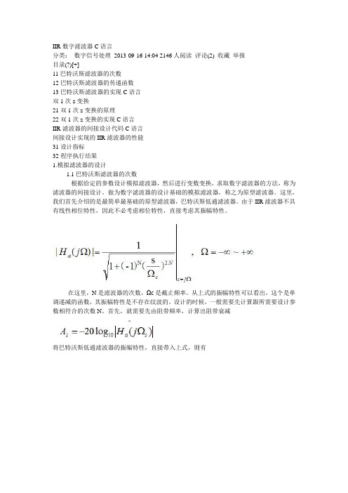
IIR数字滤波器C语言分类:数字信号处理2013-09-16 14:04 2146人阅读评论(2) 收藏举报目录(?)[+]11巴特沃斯滤波器的次数12巴特沃斯滤波器的传递函数13巴特沃斯滤波器的实现C语言双1次z变换21双1次z变换的原理22双1次z变换的实现C语言IIR滤波器的间接设计代码C语言间接设计实现的IIR滤波器的性能31设计指标32程序执行结果1.模拟滤波器的设计1.1巴特沃斯滤波器的次数根据给定的参数设计模拟滤波器,然后进行变数变换,求取数字滤波器的方法,称为滤波器的间接设计。
做为数字滤波器的设计基础的模拟滤波器,称之为原型滤波器。
这里,我们首先介绍的是最简单最基础的原型滤波器,巴特沃斯低通滤波器。
由于IIR滤波器不具有线性相位特性,因此不必考虑相位特性,直接考虑其振幅特性。
在这里,N是滤波器的次数,Ωc是截止频率。
从上式的振幅特性可以看出,这个是单调递减的函数,其振幅特性是不存在纹波的。
设计的时候,一般需要先计算跟所需要设计参数相符合的次数N。
首先,就需要先由阻带频率,计算出阻带衰减将巴特沃斯低通滤波器的振幅特性,直接带入上式,则有最后,可以解得次数N为当然,这里的N只能为正数,因此,若结果为小数,则舍弃小数,向上取整。
1.2巴特沃斯滤波器的传递函数巴特沃斯低通滤波器的传递函数,可由其振幅特性的分母多项式求得。
其分母多项式根据S解开,可以得到极点。
这里,为了方便处理,我们分为两种情况去解这个方程。
当N 为偶数的时候,这里,使用了欧拉公式。
同样的,当N为奇数的时候,同样的,这里也使用了欧拉公式。
归纳以上,极点的解为上式所求得的极点,是在s平面内,在半径为Ωc的圆上等间距的点,其数量为2N个。
为了使得其IIR滤波器稳定,那么,只能选取极点在S平面左半平面的点。
选定了稳定的极点之后,其模拟滤波器的传递函数就可由下式求得。
1.3巴特沃斯滤波器的实现(C语言)首先,是次数的计算。
次数的计算,我们可以由下式求得。
IIR滤波器的C实现

IIR滤波器的C实现IIR滤波器的C实现2012-04-10 13:58:54| 分类: Matlab | 标签: |字号大中小订阅第一步:点击菜单中的Edit->Convert Structure 选择Direct Form I ,SOS,(必须是Direct Form I, II不行)一般情况下,按照默认设置,fdatool设计都是由二阶部分串联组成的。
这种结构的滤波器稳定性比一个section的要好很多,其他方面的性能也好些。
如果不是的话,点击Convert to second order sections。
这时,滤波器的结构(structure)应该显示为Direct Form I,second order sections第二步:选择quantize filter,精度选择single precision floating point (单精度浮点)之所以不用定点是因为噪声太大,也不容易稳定。
点击菜单中的Targets -> generate c header ,选择export as:single precision floating point (单精度浮点)填写变量名称时,把NUM改成IIR_B,DEN改成IIR_A,其他不用动,保存为iir_coefs.h保存好的文件如下://一大堆注释//然后:/* General type conversion for MATLAB generated C-code */ #include "tmwtypes.h"/** Expected path to tmwtypes.h* C:\Program Files\MATLAB\R2010a\extern\include\tmwtypes.h*//** Warning - Filter coefficients were truncated to fit specified data type.* The resulting response may not match generated theoretical response.* Use the Filter Design & Analysis T ool to design accurate * single-precision filter coefficients.*/#define MWSPT_NSEC 9const int NL[MWSPT_NSEC] = { 1,3,1,3,1,3,1,3,1 };const real32_T IIR_B[MWSPT_NSEC][3] = {{0.8641357422, 0, 0},{1, -2, 1},{0.9949035645, 0, 0},{1, -1.999938965, 1},{0.9985351563, 0, 0},1, -1.99987793, 1},{0.9996337891, 0, 0},{1, -1.99987793, 1},{1, 0, 0}};const int DL[MWSPT_NSEC] = { 1,3,1,3,1,3,1,3,1 }; const real32_T IIR_A[MWSPT_NSEC][3] = {{1, 0, 0},{1, -1.938049316, 0.9401855469},{1, 0, 0},{1, -1.989501953, 0.9900512695},{1, 0, 0},1, -1.996887207, 0.9971923828},{1, 0, 0},{1, -1.999084473, 0.9993286133},{1, 0, 0}};第三步:打开iir_coefs.h把MWSPT_NSEC替换成IIR_NSEC, NL、DL数组删除掉,real32_T改成float ,其中有一个#include "twmtypes.h",不要它了,删掉改完的文件如下:#define IIR_NSEC 9//原来叫做MWSPT_NSECconst float IIR_B[IIR_NSEC][3] = {//为什么改为float很明显了吧{0.8641357422, 0, 0},{1, -2, 1},{0.9949035645, 0, 0{1, -1.999938965, 1},{0.9985351563, 0, 0 },{1, -1.99987793, 1},{0.9996337891, 0, 0 },{1, -1.99987793, 1},{1, 0, 0}};const float IIR_A[IIR_NSEC][3] = { {1, 0, 0},{1, -1.938049316, 0.9401855469 },{1, 0, 0},1, -1.989501953, 0.9900512695},{1, 0, 0},{1, -1.996887207, 0.9971923828},{1, 0, 0},{1, -1.999084473, 0.9993286133},{1, 0, 0}};保存文件,然后使用以下代码进行滤波这段代码是根据Direct Form I 2阶IIR滤波的差分方程编写的a0*y[n] = b0*x[n] + b1*x[n-1] + b2*x[n-2] - a1*y[n-1] -a2*y[n-2];//iir_filter.c#include "datatype.h"#include "iir_filter.h"#include "iir_coefs.h"static float y[IIR_NSEC][3];static float x[IIR_NSEC+1][3];int16 iir_filter(int16 in)uint16 i;x[0][0] = in;for(i=0;i<IIR_NSEC;i++){y[0] =x[0]*IIR_B[0]+x[1]*IIR_B[1]+x[2]*IIR_B[2]-y[1]*IIR_A[1]-y[2]*IIR_A[2];y[0] /= IIR_A[0];y[2]=y[1];y[1]=y[0];x[2]=x[1];x[1]=x[0];x[i+1][0] = y[0];}if( x[IIR_NSEC][0]>32767) x[IIR_NSEC][0]=32767;if( x[IIR_NSEC][0]<-32768) x[IIR_NSEC][0]=-32768;return ((int16)x[IIR_NSEC][0]);}//复位滤波器void iir_reset(void){uint16 i,j;for(i=0;i<IIR_NSEC+1;i++){for(j=0;j<3;j++){x[j]=0;}}for(i=0;i<IIR_NSEC;i++){for(j=0;j<3;j++){y[j]=0;}}}//iir_filter.h#ifndef _IIR_FILTER_H__#define _IIR_FILTER_H__int16 iir_filter(int16 x);void iir_reset(void);#endif使用方法:首先写好iir_coefs.h,然后调用iir_filter.c对数据流进行滤波一个伪代码例子:while(运行中){保存到SD卡(iir_filter(读取ADC采样值()));}这个函数比STM32 DSP库中的函数要好很多,DSP库中的2个IIR滤波函数都不能连续处理数据流。
单片机中IIR滤波器的实现

单片机中(C语言)IIR滤波器的实现转载原文参见https:///qq_21905401/article/details/53894517 IIR是无限长单位脉冲响应数字滤波器,其系统对应函数有如下形式:在知道滤波器相应的系数b[],a[]后可根据相应的差分方程,完成对数据的滤波,而滤波器的系数可以通过Matlab滤波器设计和分析工具箱Filter Design&Analysis Tool求得,下面以一个IIR三阶低通滤波器为例,介绍C语言IIR滤波器的实现方法:1、计算滤波器的系数根据信号的采样频率以及低通滤波器的截止频率,通过Matlab工具箱求得滤波器的系数b和a。
如信号采样率为f=400Hz,低通滤波器的截止频率fc=60Hz:Matlab中Start→ToolBoxes→Filter Design→Filter Design & Analysis Tool(fdatool)在Filter Design & Analysis Tool,输入滤波器的相应指标,点击“Design Filter”设计滤波器。
如下图所示:通过Analysis→Filter coefficients查看所设计滤波器系数:响应函数:2、差分方程C语言实现根据相应函数得到差分方程:a[0]*y[i]=Gain*(b[0]*x[i]+b[1]*x[i-1]+b[2]*x[i-2])-a[1]*y[i-1]-a[2]*y(n-2)其中Gain=0.146747,b[]={1,2,1},a[]={1,-0.837000,0.42398},x[i]为输入信号,y[i]为滤波后信号。
C语言实现代码如下:B[0]=1;B[1]=2;B[2]=1;A[0]=1;A[1]=-0.837000;A[2]=0.42398;Gain=0.146747;w_x[0]=w_x[1]=w_x[2]=0;w_y[0]=w_y[1]=w_y[2]=0;for(int i=0;i<len;i++){w_x[0]=x[i];w_y[0]=(B[0]*w_x[0]+B[1]*w_x[1]+B[2]*w_x[2])*Gain-w_y[1]*A[1]-w_y[2]*A[2];y[i]=w_y[0]/A[0];w_x[2]=w_x[1];w_x[1]=w_x[0];w_y[2]=w_y[1];w_y[1]=w_y[0];}也可以使用如下代码:w[0]=w[1]=w[2]=0;for(int i=0;i<len;i++){w[0]=A[0]*x[i]-A[1]*w[2]-A[2]*w[2];y[i]=(B[0]*w[0]+B[1]*w[1]+B[2]*w[2])*Gain;w[2]=w[1];w[1]=w[0];}注意:在滤波之前,需要将系数w_x[]、w_y[]、w置零。
用Matlab的FDAtool生成IIR滤波器参数以及参数生成C 语言文件

用Matlab的FDAtool生成IIR滤波器参数MATLAB IIR数字滤波器设计首先我们要明白相关的概念。
数字滤波器设计采用角频率,如何与实际信号频率对应?角频率w,采样频率fs ,实际信号频率f的转换关系为:W = 2*pi* f / fs采样频率的角频率为 2 *pi.数字滤波器的指标,以低通为例【见下图】:当我们设计的滤波器是带通的时候。
其通带截止频率有两个,阻带截止频率也有两个。
截止频率还有另外一个称谓,即边沿频率。
FIR 滤波器可以设计为线性相位,并且总是稳定的。
在多数情况下,FIR滤波器的阶数NFIR 显著大于具有等效幅度响应的IIR滤波器阶数NIIR。
NFIR/NIIR 通常为10的量级或更高. IIR 滤波器通常计算更简便。
在很多应用中,并不要求滤波器具有严格的线性相位,在这些情况下,通常会因计算简便而选择IIR滤波器。
例如在很多语音编码当中的滤波器很多都是IIR 滤波器,均衡器一般也用IIR滤波器。
也就是说对实时性要求不是很高的场合可以考虑使用FIR滤波器,当FIR滤波器阶数较长时,可以考虑用FFT去计算。
在设计IIR滤波器时,通常将数字滤波器的设计指标转化成模拟低通原型滤波器的设计指标,从而确定满足这些指标的模拟低通滤波器的传输函数Ha(s),然后再将它变换成所需要的数字滤波器传输函数G(z)。
上述滤波器设计的过程只需要了解其原理。
借助于MATLAB强大的工具,滤波器的设计变得比较简单了。
在MATLAB命令窗口中键入fdatool, 你将启动滤波器设计的图形界面。
你可以从simulink 中直接选择数字滤波器控件而启动。
本文主要讲述IIR数字滤波器设计的方法。
对从麦克风进来的信号滤波。
假定我们要把50hz的电频干扰去掉,同时人说话的频率一般不会超过3400hz。
我们设计一个带通滤波器,通带为【80-3200】,采样率为8k。
根据上面的需求,我们把相关的参数改成下面的界面:单击 Design Filter,数秒之后显示如下:可以看出:滤波器的阶数是36,还有一个 sections: 18. 由于在具体实现时一般是以2阶的级联或并联去实现的。
IIR数字滤波器设计 上机程序 c语言

一)x1(t)=4sin(100πt) Ts=1.25ms,T=80ms Ωp=2/Ts*tan(wp/2)=519.87rad/s,Ωs=815.24rad/s#include<math.h>#include<stdio.h>void IIRDF(float A[],unsigned long N);void fft(float A[],float B[],unsigned M);main(){float A[1024],B[1024],C[1024],D[1024],F[1024];//A[i],D[i]存储输入序列实部,B[i],F[i]存储输入序列虚部unsigned long N,i ,M;printf("input M=");scanf("%d",&M);N=1<<M;printf("input A[]:");for(i=0;i<N;i++){A[i]=4*sin((100*3.1415926*1.25/1000)*i);D[i]=4*sin((100*3.1415926*1.25/1000)*i);}for(i=0;i<N;i++){B[i]=0;F[i]=0;}printf("x(n):");for(i=0;i<N;i++)printf("x(%d)=%f",i,A[i]); //输出采样序列的值fft(A,B,M); //对输入的离散序列进行FFT,求其频谱for(i=0;i<N;i++)C[i]=sqrt(A[i]*A[i]+B[i]*B[i]); //C[i]为输入离散序列的频谱幅值printf("x(k):");for(i=0;i<N;i++)printf("X[%d]=%f\n",i,C[i]); //输出C[i]for(i=0;i<N;i++)B[i]=0; IIRDF(D,N);//A[i]已被占用,故用D[i]存储的输入序列通过低通滤波器,F[i]同理printf("y(n):"); //通过低通滤波器后的输出序列for(i=0;i<N;i++)printf("y(%d)=%f\n",i,D[i]);fft(D,F,M); //对输出序列进行FFT,求其频谱printf("y(k):");for(i=0;i<N;i++)C[i]=sqrt(D[i]*D[i]+F[i]*F[i]); //C[i]为输出离散序列的频谱幅值for(i=0;i<N;i++)printf("y(%d)=%f\n",i,C[i]); //输出C[i]printf("\n");}void IIRDF(float A[],unsigned long N)/*级联型低通滤波器*/ {unsigned long n ;float x[3]={0,0,0},y1[3]={0,0,0},y2[3]={0,0,0},y[3]={0,0,0}; //y(0)表示y(n),y(1)表示y(n-1),y(2)表示y(n-2)for(n=0;n<N;n++){x[0]=A[n];y1[0]=1.31432*y1[1]-0.71489*y1[2]+0.08338*x[0]+0.16676*x[1]+0.0 8338*x[2];/*第一级*/x[2]=x[1];x[1]=x[0];y2[0]=1.0541*y2[1]-0.37534*y2[2]+0.08338*y1[0]+0.16676*y1[1]+0.0 8338*y1[2];/*第二级*/y1[2]=y1[1];y1[1]=y1[0];y[0]=0.94592*y[1]-0.23422*y[2]+0.08338*y2[0]+0.16676*y2[1]+0.083 38*y2[2];/*第三级*/y2[2]=y2[1];y2[1]=y2[0];y[2]=y[1];y[1]=y[0];A[n]=y[0];}}#define swap(a,b) T=(a); (a)=(b); (b)=Tvoid fft(float A[],float B[],unsigned M)//蝶形运算程序,A存实部,B存虚部,M是级数{unsigned long N,I,J,K,L,LE,LE1,P,Q,R;float Wr,Wi,W1r,W1i,WTr,WTi,theta,Tr,Ti;N=1<<M;J=0;for (I=0;I<N-1;I++){if(J>I){float T;swap(A[I],A[J]);swap(B[I],B[J]);}K=N>>1;while (K>=2&&J>=K){J-=K; K>>=1;}J+=K;}for(L=1;L<=M;L++) //for循环为M级FFT运算{LE=1<<L; // LE=1<<L表示2的L次幂,相当于本级运算的NLE1=LE/2; //LE1=2的L-1次幂,相当于有L-1个Wn Wr=1.0;Wi=0.0;theta=(-1)*3.1415926536/LE1; //theta相当于-2π/N,W1r=cos(theta);W1i=sin(theta);for(R=0;R<LE1;R++)//for循环为每级有2的L-1次运算,R为系数序号,LE1为系数个数{for(P=R;P<N;P+=LE) //for循环为蝶形的群运算{Q=P+LE1;Tr=Wr*A[Q]-Wi*B[Q];Ti=Wr*B[Q]+Wi*A[Q];A[Q]=A[P]-Tr;B[Q]=B[P]-Ti;A[P]+=Tr;B[P]+=Ti;}WTr=Wr;WTi=Wi;Wr=WTr*W1r-WTi*W1i;Wi=WTr*W1i+WTi*W1r;}}return;}。
二阶滤波c语言

二阶滤波c语言对于一个简单的二阶滤波器,您可以使用如下C语言代码作为示例。
这个代码实现了一个简单的二阶IIR滤波器,用于处理一维数据。
c复制代码:#include <stdio.h>// 定义滤波器系数#define ALPHA 0.5// 定义滤波器状态double x1 = 0.0, x2 = 0.0;// 二阶IIR滤波器函数double filter(double input) {double output = ALPHA * input + (1 - ALPHA) * (x1 + x2);x2 = x1;x1 = input;return output;}int main() {// 输入数据(您可以在这里替换为实际数据)double input[] = {1.0, 2.0, 3.0, 4.0, 5.0};int size = sizeof(input) / sizeof(input[0]);// 对输入数据进行滤波处理for (int i = 0; i < size; i++) {double output = filter(input[i]);printf("Input: %f, Filtered Output: %f\n", input[i], output);}return 0;}在这个示例中,滤波器系数ALPHA是可调的,您可以根据需要调整它以改变滤波器的特性。
x1和x2是滤波器的状态,分别存储了上一次和上上一次的输入值。
每次调用filter 函数时,都会更新这些状态并返回滤波后的输出。
iir滤波c语言

iir滤波c语言IIR滤波(Infinite Impulse Response Filter)是一种数字滤波器,常用于信号处理和实时系统中。
本文将介绍IIR滤波器的基本原理、设计方法以及在C语言中的实现。
一、IIR滤波器的基本原理IIR滤波器是一种反馈滤波器,其输出不仅与当前的输入值有关,还与过去的输入值和输出值有关。
它的基本原理是通过将输入信号与滤波器的传递函数进行卷积运算,得到滤波器的输出信号。
二、IIR滤波器的设计方法1. 频率响应设计方法:通过设定所需的频率响应曲线,设计出相应的传递函数来实现滤波器。
常用的设计方法有巴特沃斯(Butterworth)滤波器、切比雪夫(Chebyshev)滤波器和椭圆(Elliptic)滤波器等。
2. 零极点设计方法:通过设定零点和极点的位置来设计滤波器的传递函数。
常用的设计方法有双线性变换法、脉冲响应不变法和双正交变换法等。
三、IIR滤波器的C语言实现在C语言中,可以通过差分方程的形式来实现IIR滤波器。
差分方程描述了滤波器的输入输出关系,可以用递归的方式计算滤波器的输出。
以下是一个简单的IIR滤波器的C语言实现示例:```ctypedef struct {float a[ORDER+1]; // 系数a的数组float b[ORDER+1]; // 系数b的数组float x[ORDER+1]; // 输入信号的数组float y[ORDER+1]; // 输出信号的数组}IIRFilter;void IIRFilter_Init(IIRFilter *filter) {int i;for(i = 0; i <= ORDER; i++) {filter->a[i] = 0.0;filter->b[i] = 0.0;filter->x[i] = 0.0;filter->y[i] = 0.0;}}float IIRFilter_Process(IIRFilter *filter, float input) { int i;float output = 0.0;for(i = ORDER; i >= 1; i--) {filter->x[i] = filter->x[i-1];filter->y[i] = filter->y[i-1];}filter->x[0] = input;for(i = 0; i <= ORDER; i++) {output += filter->b[i] * filter->x[i];output -= filter->a[i] * filter->y[i];}filter->y[0] = output;return output;}```在以上代码中,IIRFilter结构体定义了滤波器的系数和状态变量,IIRFilter_Init函数用于初始化滤波器,IIRFilter_Process函数用于处理输入信号并返回输出信号。
二阶IIR滤波器C代码实现

⼆阶IIR滤波器C代码实现#define PI 3.14159265358979323846typedef double sample_t;enum {BIQUAD_LOWPASS,BIQUAD_HIGHPASS,BIQUAD_BANDPASS_PEAK,};typedef struct{sample_t a0, a1, a2, a3, a4;sample_t x1, x2, y1, y2;}biquad_state;// 计算滤波器的系数,2nd-order Butterworth: q_value=0.7071 ,2nd-order Chebyshev (ripple 1 dB): q_value=0.9565,2nd-order Thomson-Bessel: // q_value=0.5773。
带通滤波器的q_value = sqrt(f1*f2)/(f2-f1),fs是指信号的采样频率,fc为cutoff frequence 或者是centern frequenc(带通滤波器) void filter_init(biquad_state *state, int type, int fs, float fc, float q_value){sample_t w0, sin_w0, cos_w0, alpha;sample_t b0, b1, b2, a0, a1, a2;w0 = 2 * PI * fc / fs;sin_w0 = sin(w0);cos_w0 = cos(w0);alpha = sin_w0 / (2.0 * q_value);switch(type){case BIQUAD_LOWPASS:b0 = (1.0 - cos_w0) / 2.0;b1 = b0 * 2;b2 = b0;a0 = 1.0 + alpha;a1 = -2.0 * cos_w0;a2 = 1.0 - alpha;break;case BIQUAD_HIGHPASS:b0 = (1.0 + cos_w0) / 2.0;b1 = -b0 * 2;b2 = b0;a0 = 1.0 + alpha;a1 = -2.0 * cos_w0;a2 = 1.0 - alpha;break;case BIQUAD_BANDPASS_PEAK:b0 = alpha;b1 = 0.0;b2 = -alpha;a0 = 1.0 + alpha;a1 = -2.0 * cos_w0;a2 = 1.0 - alpha;break;}state->a0 = b0 / a0;state->a1 = b1 / a0;state->a2 = b2 / a0;state->a3 = a1 / a0;state->a4 = a2 / a0;state->x1 = state->x2 = 0.0;state->y1 = state->y2 = 0.0;}//biquard滤波sample_t biquad(biquad_state *state, sample_t data){sample_t result = 0;result = state->a0 * data + state->a1 * state->x1 + state->a2 * state->x2 - state->a3 * state->y1 - state->a4 * state->y2;state->x2 = state->x1;state->x1 = data;state->y2 = state->y1;state->y1 = result;return result;}int main(int argc, char **argv) {biquad_state *stat = (biquad_state *) malloc(sizeof(biquad_state));int numbers = 1024;float fs = 1024;sample_t data[numbers], filter_data[numbers];float fc = 50;float q_value = 0.7071;int type = BIQUAD_LOWPASS;filter_init(stat, type, fs, fc, q_value);for (int i = 0; i <numbers; ++i){ data[i] = 0.5 * (sin(2 * PI * 40 * i / fs) + cos(2 * PI * 150 * i / fs + PI / 4)); }for (int i = 0; i <numbers; ++i){filter_data[i] = biquad(stat, data[i]);}free(stat);}。
simulink中iir一阶低通滤波c语言实现

simulink中iir一阶低通滤波c语言实现要在C语言中实现IIR(无限冲激响应)一阶低通滤波器,您需要首先理解滤波器的数学模型。
一阶低通滤波器的传递函数可以表示为:makefile复制代码H(z) = 1 / (1 + a*z^-1)其中a是滤波器的参数,控制着滤波器的性能。
以下是一个简单的C语言实现,它使用了一个一维数组来存储输入和输出信号,以及一个循环来迭代地应用滤波器。
注意,这只是一个简单的示例,可能不适用于所有应用,特别是在实时系统中,可能需要考虑更多的优化和异常处理。
c复制代码#include<stdio.h>#define N 100 // 定义数组大小double input[N]; // 输入信号数组double output[N]; // 输出信号数组double a = 0.5; // 滤波器参数void apply_filter(double* input, double* output, int length) {for (int i = 0; i < length; i++) {output[i] = input[i] / (1.0 + a * input[i]);}}int main() {// 初始化输入和输出数组(这里只是示例数据)for (int i = 0; i < N; i++) {input[i] = i; // 示例输入数据}for (int i = 0; i < N; i++) {output[i] = 0; // 清空输出数组}// 应用滤波器apply_filter(input, output, N);// 打印输出结果(这里只是示例)for (int i = 0; i < N; i++) {printf("%f\n", output[i]); // 打印输出结果(这里只是示例)}return0;}在上述代码中,我们定义了一个apply_filter函数,它接受输入和输出数组以及数组长度作为参数,并应用滤波器。
iir滤波算法c语言
iir滤波算法c语言The IIR (Infinite Impulse Response) filter is a digital filter commonly used in signal processing applications. It is a recursive filter that utilizes feedback to achieve its filtering characteristics. In this response, we will explore the IIR filter algorithm in the C programming language, discussing its working principle, implementation, advantages, disadvantages, and applications.The IIR filter algorithm operates by recursively applying a set of coefficients to the input signal and its previous output samples. This recursive nature allows the filter to have an infinite impulse response, meaning it can have a long-lasting effect on the output signal. Thefilter's response is determined by its transfer function, which is defined by the coefficients used in the algorithm.Implementing the IIR filter algorithm in C requires a basic understanding of digital signal processing concepts and programming skills. The algorithm involves maintaininga buffer to store the previous output samples, updating the buffer with each new input sample, and performing the filtering operation using the defined coefficients. The output of the filter is calculated by summing the products of the input and coefficient values.One advantage of the IIR filter algorithm is its efficiency in terms of computational resources. Compared to the FIR (Finite Impulse Response) filter, the IIR filter requires fewer operations, making it suitable for real-time applications with limited processing power. Additionally, IIR filters can achieve sharper frequency response characteristics, allowing for more precise filtering of specific frequency ranges.However, the IIR filter algorithm also has certain disadvantages. One major drawback is its susceptibility to instability. Due to the recursive nature of the filter, it can exhibit unstable behavior if the coefficient values are not carefully chosen. This instability can lead to unpredictable and undesirable output signals. Therefore, careful design and analysis of the filter coefficients arecrucial to ensure stability.The IIR filter algorithm finds applications in various domains, including audio processing, image filtering, telecommunications, and biomedical signal analysis. In audio processing, IIR filters are commonly used for tasks such as equalization, noise reduction, and echo cancellation. In image filtering, these filters can be employed for tasks like edge detection and image enhancement. In telecommunications, IIR filters are used for channel equalization and interference suppression. In biomedical signal analysis, these filters are utilized for tasks like ECG (Electrocardiogram) denoising and EEG (Electroencephalogram) analysis.In conclusion, the IIR filter algorithm in the C programming language is a powerful tool for digital signal processing applications. Its recursive nature allows for efficient processing and sharper frequency response characteristics. However, careful consideration must be given to stability issues when designing and implementing IIR filters. With its wide range of applications, the IIRfilter algorithm continues to play a significant role in various fields, contributing to advancements in signal processing and analysis.。
iir数字滤波器设计及c语言程序
iir数字滤波器设计及c语言程序IIR数字滤波器设计及C语言程序IIR(Infinite Impulse Response)数字滤波器是一种常用的数字信号处理技术,广泛应用于音频处理、图像处理、通信系统等领域。
本文将介绍IIR数字滤波器的设计原理,并给出相应的C语言程序实现。
一、IIR数字滤波器的设计原理IIR数字滤波器的设计基于差分方程,其输入信号和输出信号之间存在一定的差分关系。
相比于FIR(Finite Impulse Response)数字滤波器,IIR数字滤波器具有更窄的转换带宽、更高的滤波器阶数和更好的相位响应等特点。
IIR数字滤波器的设计主要包括两个关键步骤:滤波器规格确定和滤波器参数计算。
首先,根据实际需求确定滤波器的类型(低通、高通、带通或带阻)、截止频率、通带衰减和阻带衰减等规格。
然后,根据这些规格利用数字滤波器设计方法计算出滤波器的系数,从而实现对输入信号的滤波。
二、IIR数字滤波器的设计方法常见的IIR数字滤波器设计方法有脉冲响应不变法、双线性变换法和最小均方误差法等。
下面以最常用的脉冲响应不变法为例介绍设计方法。
脉冲响应不变法的基本思想是将模拟滤波器的脉冲响应与数字滤波器的单位脉冲响应进行匹配。
首先,根据模拟滤波器的传递函数H(s)确定其脉冲响应h(t)。
然后,将连续时间下的脉冲响应离散化,得到离散时间下的单位脉冲响应h[n]。
接下来,根据单位脉冲响应h[n]计算出数字滤波器的差分方程系数,从而得到滤波器的数字表示。
三、IIR数字滤波器的C语言程序实现下面给出一个简单的IIR数字滤波器的C语言程序实现示例,以低通滤波器为例:```c#include <stdio.h>#define N 100 // 输入信号长度#define M 5 // 滤波器阶数// IIR数字滤波器系数float b[M+1] = {0.1, 0.2, 0.3, 0.2, 0.1};float a[M+1] = {1.0, -0.5, 0.3, -0.2, 0.1};// IIR数字滤波器函数float IIR_filter(float *x, float *y, int n) {int i, j;float sum;for (i = 0; i < n; i++) {sum = 0;for (j = 0; j <= M; j++) { if (i - j >= 0) {sum += b[j] * x[i - j]; }}for (j = 1; j <= M; j++) { if (i - j >= 0) {sum -= a[j] * y[i - j]; }}y[i] = sum;}}int main() {float x[N]; // 输入信号float y[N]; // 输出信号int i;// 生成输入信号for (i = 0; i < N; i++) {x[i] = i;}// IIR数字滤波器滤波IIR_filter(x, y, N);// 输出滤波后的信号for (i = 0; i < N; i++) {printf("%f ", y[i]);}return 0;}```以上是一个简单的IIR数字滤波器的C语言程序实现示例。
拉氏变换差分方程c语言,IIR数字滤波器的实现(C语言)

拉⽒变换差分⽅程c语⾔,IIR数字滤波器的实现(C语⾔)经典滤波器和数字滤波器⼀般滤波器可以分为经典滤波器和数字滤波器。
经典滤波器:假定输⼊信号中的有⽤成分和希望去除的成分各⾃占有不同的频带。
如果信号和噪声的频谱相互重迭,经典滤波器⽆能为⼒。
⽐如 FIR 和 IIR 滤波器等。
现代滤波器:从含有噪声的时间序列中估计出信号的某些特征或信号本⾝。
现代滤波器将信号和噪声都视为随机信号。
包括 Wiener Filter、Kalman Filter、线性预测器、⾃适应滤波器等Z变换和差分⽅程在连续系统中采⽤拉普拉斯变换求解微分⽅程,并直接定义了传递函数,成为研究系统的基本⼯具。
在采样系统中,连续变量变成了离散量,将Laplace变换⽤于离散量中,就得到了Z变换。
和拉⽒变换⼀样,Z变换可⽤来求解差分⽅程,定义Z传递函数成为分析研究采样系统的基本⼯具。
对于⼀般常⽤的信号序列,可以直接查表找出其Z变换。
相应地,也可由信号序列的Z变换查出原信号序列,从⽽使求取信号序列的Z变换较为简便易⾏。
Z变换有许多重要的性质和定理:线性定理设a,a1,a2为任意常数,连续时间函数f(t),f1(t),f2(t)的Z变换分别为F(z),F1(z),F2(z),则有$$\mathbf{Z}[af(t)]=aF(z)$$ $$ \mathbf{Z}[a_1f_1(t)+a_2f_2(t)]=a_1F_1(z)+a_2F_2(z)$$滞后定理设连续时间函数在t<0时,f(t)=0,且f(t)的Z变换为F(z),则有$$\mathbf{Z}[f(t-kT)]=z^{-k}F(z)$$应⽤Z变换求解差分⽅程的⼀个例⼦:已知系统的差分⽅程表达式为$y(n)-0.9y(n-1)=0.05u(n)$,若边界条件$y(-1)=1$,求系统的完全响应。
解:⽅程两端取z变换$$Y(z)-0.9[z^{-1}Y(z)+y(-1)]=0.05\frac{z}{z-1}\\Y(z)=\frac{0.05z^2}{(z-1)(z-0.9)}+\frac{0.9y(-1)z}{z-0.9}$$可得$$\frac{Y(z)}{z}=\frac{A_1z}{z-1}+\frac{A_2z}{z-0.9}$$其中A1=0.5,A2=0.45,于是$y(n)=0.5+0.45 \times(0.9)^n \quad(n\geq0)$IIR数字滤波器的差分⽅程和系统函数IIR数字滤波器是⼀类递归型的线性时不变因果系统,其差分⽅程可以写为:$$y(n)=\sum_{i=0}^{M}a_ix(n-i)+\sum_{i=1}^{N}b_iy(n-i)$$进⾏Z变换,可得:$$Y(z)=\sum_{i=0}^{M}a_iz^{-i}X(z)+\sum_{i=1}^{N}b_iz^{-i}Y(z)$$于是得到IIR数字滤波器的系统函数:$$H(z)=\frac{Y(z)}{X(z)}=\frac{\sum_{i=0}^{M}a_iz^{-i}}{1-\sum_{i=1}^{N}b_iz^{-i}}=a_0\frac{\prod_{i=1}^{M}(1-c_iz^{-1})}{\prod_{i=1}^{N}(1-d_iz^{-1})}$$其中ci为零点⽽di为极点。
c语言实现iir椭圆滤波

c语言实现iir椭圆滤波
实现IIR(Infinite Impulse Response)椭圆滤波器需要一定的数学和C语言编程知识。
椭圆滤波器是一种数字滤波器,可以用于信号处理和数字通信中。
在C语言中实现IIR椭圆滤波器需要以下步骤:
1. 设计滤波器,首先,你需要根据滤波器的要求和规格设计椭圆滤波器的参数,包括通带频率、阻带频率、通带和阻带的最大衰减等。
这通常需要使用数字信号处理工具箱或者专门的滤波器设计软件来完成。
2. 转换为差分方程,一旦设计好滤波器,你需要将其转换为差分方程。
椭圆滤波器通常由二阶节组成,每个二阶节对应一个二阶差分方程,可以使用数字信号处理知识来进行转换。
3. 实现差分方程,将差分方程转换为C语言代码。
这涉及到使用递归或迭代方法来实现滤波器的差分方程,通常需要使用循环和数组来存储历史输入和输出。
4. 测试和调试,实现完滤波器后,需要进行测试和调试,以确
保滤波器按照设计要求正常工作。
在C语言中实现IIR椭圆滤波器需要深入理解数字信号处理和C语言编程,同时需要对滤波器设计和差分方程的转换有一定的了解。
同时,为了更好地理解和实现椭圆滤波器,建议阅读相关的数字信号处理和滤波器设计的教材和资料。
一阶iir滤波器 c语言
一阶IIR(Infinite Impulse Response,无限脉冲响应)滤波器是一种常见的数字滤波器,可用于信号处理中的滤波操作。
下面是一个使用C语言实现一阶IIR滤波器的示例代码:```c// 定义一阶IIR滤波器结构体typedef struct {float a; // 反馈系数float b; // 前馈系数float prev_input; // 上一个输入样本float prev_output; // 上一个输出样本} IIRFilter;// 初始化滤波器void initIIRFilter(IIRFilter* filter, float a, float b) {filter->a = a;filter->b = b;filter->prev_input = 0.0f;filter->prev_output = 0.0f;}// 应用滤波器float applyIIRFilter(IIRFilter* filter, float input) {float output = filter->b * input + filter->a * filter->prev_input - filter->a * filter->prev_output;filter->prev_input = input;filter->prev_output = output;return output;}```使用上述代码,你可以按照以下步骤来创建和使用一阶IIR滤波器:1. 创建一个 `IIRFilter` 结构体,并使用 `initIIRFilter` 函数初始化滤波器,设置反馈系数和前馈系数。
2. 在每次需要进行滤波的时候,调用 `applyIIRFilter` 函数,并传入当前的输入样本。
函数将返回滤波后的输出样本。
下面是一个使用示例:```cint main() {IIRFilter filter;float input = 1.0f; // 输入样本// 初始化滤波器,设置反馈系数和前馈系数initIIRFilter(&filter, 0.5f, 0.5f);// 应用滤波器,获取输出样本float output = applyIIRFilter(&filter, input);// 打印输出结果printf("Output: %f\n", output);return 0;}```以上示例演示了如何创建一阶IIR滤波器并对输入样本进行滤波。
IIR滤波器设计程序

IIRD_DF.c-双线性变换法设计IIR数字滤波器Infinite Impulse Response Digital Filter Design By Double Converting====================================================包括1.Lowpass 2.Highpass 3.bandpass三部分,如果有特殊需要把其他部分删除掉即可。
***********************************************************//*#include <windows.h>*/#include <math.h>#include <dos.h>#include <stdlib.h>#include <stdio.h>#include <string.h>#include <conio.h>#include <graphics.h>/*COMPLEX STRUCTURE*/typedef struct{double real,image;}COMPLEX;struct rptr{double *a;double *b;};#define PI (double)(4.0*atan(1.0))#define FNSSH(x) log(x+sqrt(x*x+1))#define FNCCH(x) log(x+sqrt(x*x-1))#define FNSH1(x) (exp(x)-exp(-x))/2#define FNCH1(x) (exp(x)+exp(-x))/2/********************************************************************************* **************/double *bcg(double ap,double as,double wp,double ws,int *n,double *h,int *type);struct rptr *bsf(double *c,int ni,double *f1,double *f2,int nf,struct rptr *ptr,int *no);double *pnpe(double *a,int m,int n,double *b,int *mn);double *ypmp(double *a,int m,double *b,int n,double *c,int *mn);void lowpass_input(double *wp,double *ws,double *ap,double *ar,double *f1,double *f2,int *nf); void highpass_input(double *wp,double *ws,double *ap,double *ar,double *f1,double *f2,int *nf); void bandpass_input(double *wp,double *ws,double *ap,double *ar,double *f1,double *f2,int *nf); void draw_image(double *x,int m,char *title1,char *title2,char *xdis1,char *xdis2,int dis_type);/*********************************************************************************** ************/void main(void){double *f1,*f2,*hwdb;double *h=NULL;int N,nf,ns,nz,i,j,k,ftype,type;COMPLEX hwdb1,hwdb2;double wp,ws,ap,as,jw,amp1,amp2;char title[80],tmp[20];struct rptr *ptr=NULL;/* printf("%lf",PI);getch();*/N=500;f1=(double *)calloc(4,sizeof(double));f2=(double *)calloc(4,sizeof(double));hwdb=(double *)calloc(N+2,sizeof(double));if (hwdb==NULL){printf("\n Not enough memory to allocate!");exit(0);}printf("\n1.Lowpass 2.Highpass 3.bandpass");printf("\nPlease select the filter type:");scanf("%d",&ftype);switch(ftype){case 1:lowpass_input(&wp,&ws,&ap,&as,f1,f2,&nf);break;case 2:highpass_input(&wp,&ws,&ap,&as,f1,f2,&nf);break;case 3:bandpass_input(&wp,&ws,&ap,&as,f1,f2,&nf);break;default:lowpass_input(&wp,&ws,&ap,&as,f1,f2,&nf);}h=bcg(ap,as,wp,ws,&ns,h,&type);printf("\nThe analog filter denominator coefficients of Ha(s):");for(i=0;i<=ns;i++)printf("\nb[%2d]=%16f",i,h[i]);ptr=bsf(h,ns,f1,f2,nf,ptr,&nz);printf("\nThe digital filter coefficients of H(z):");printf("\n(a is numerator coefficient. b is denominator coefficient.)");for(i=0;i<=nz;i++)printf("\na[%2d]=%10f,b[%2d]=%16f",i,ptr->a[i],i,ptr->b[i]);printf("\n\nPress any key to calculate the filter response of H(z)..."); getch();printf("\nWaitting for calculating...");/* Calculate the magnitude-frequency response*/for(k=0;k<=N;k++){jw=k*PI/N;hwdb1.real=0;hwdb1.image=0;hwdb2.real=0;hwdb2.image=0;for(i=0;i<=nz;i++){hwdb1.real+=ptr->a[i]*cos(i*jw);hwdb2.real+=ptr->b[i]*cos(i*jw);hwdb1.image+=ptr->a[i]*sin(i*jw);hwdb2.image+=ptr->b[i]*sin(i*jw);}amp1=(pow(hwdb1.real,2)+pow(hwdb1.image,2));amp2=(pow(hwdb2.real,2)+pow(hwdb2.image,2));if(amp1==0) amp1=1e-90;if(amp2==0) amp2=1e-90;hwdb[k]=10*log10(amp1/amp2);if(hwdb[k]<-200) hwdb[k]=-200;if(k%10==9) printf("*");}strcpy(title,"Transfer Property");if(type==1) strcat(title,"(BW Type) N=");if(type==2) strcat(title,"(CB Type) N=");itoa(ns,tmp,10);strcat(title,tmp);strcpy(tmp,"PI(rad)");draw_image(hwdb,N,title,"The Attenuation(dB)","0",tmp,0);free(ptr->b);free(ptr->a);free(h);free(hwdb);free(f2);free(f1);}/***************************************************************/void lowpass_input(double *wp,double *ws,double *ap,double *ar,double *f1,double *f2,int *nf){double fp,fr,fs;printf("\nPlease input the Fp,Ap,Fr,Ar,Fs value");printf("\nFp,Ap:Passband frequency(Hz) and MAXAttenuation(dB)");printf("\nFr,Ar:Stopband frequency(Hz) and MINAttenuation(dB)");printf("\nFs is the sample frequency(Hz) Lowpass filter");printf("\nInput parameters Fp,Ap,Fr,Ar,Fs:");scanf("%lf,%lf,%lf,%lf,%lf",&fp,ap,&fr,ar,&fs);if((fp>fr)||(*ap>*ar)||(fs<2*fr)){do{sound(1000);delay(200);nosound();printf("Invalid input! Please Reinput:");scanf("%lf,%lf,%lf,%lf,%lf",&fp,ap,&fr,ar,&fs);}while((fp>fr)||(*ap>*ar)||(fs<2*fr));}*wp=tan(PI*fp/fs);*ws=tan(PI*fr/fs);*f1=-1.0;*(f1+1)=1.0;*f2=1.0;*(f2+1)=1.0;*nf=1;}/*********************************************************************************** ***********/void highpass_input(double *wp,double *ws,double *ap,double *ar,double *f1,double *f2,int *nf) {double fp,fr,fs;printf("\nPlease input the Fp,Ap,Fr,Ar,Fs value");printf("\nFp,Ap:Passband frequency(Hz) and MAXAttenuation(dB)");printf("\nFr,Ar:Stopband frequency(Hz) and MINAttenuation(dB)");printf("\nFs is the sample frequency(Hz) highpass filter");printf("\nInput parameters Fp,Ap,Fr,Ar,Fs:");scanf("%lf,%lf,%lf,%lf,%lf",&fp,ap,&fr,ar,&fs);if((fp*ar)||(fs<2*fp)){do{sound(1000);delay(200);nosound();printf("Invalid input! Please Reinput:");scanf("%lf,%lf,%lf,%lf,%lf",&fp,ap,&fr,ar,&fs);}while((fp*ar)||(fs<2*fr));}*wp=fabs(1/tan(PI*fp/fs));*ws=fabs(1/tan(PI*fr/fs));*f1=1.0;*(f1+1)=1.0;*f2=-1.0;*(f2+1)=1.0;*nf=1;}/****************************************************************************/ void bandpass_input(double *wp,double *ws,double *ap,double *ar,double *f1,double *f2,int *nf) {double fp1,fp2,fr1,fr2,fs,wp1,wp2,wr1,wr2,cw0,pwp1,pwp2,pws1,pws2;printf("\nPlease input the Fp1,Fp2,Ap,Fr1,Fr2,,Ar,Fs value");printf("\nFp1,Fp2,Ap:Passband frequency(Hz) and MAXAttenuation(dB)");printf("\nFr1,Fr2,Ar:Stopband frequency(Hz) and MINAttenuation(dB)");printf("\nFs is the sample frequency(Hz) bandpass filter");printf("\nInput parameters Fp1,Fp2,Ap,Fr1,Fr2,Ar,Fs:");scanf("%lf,%lf,%lf,%lf,%lf,%lf,%lf",&fp1,&fp2,ap,&fr1,&fr2,ar,&fs);if((fp1>fp2)||(fp1fr2)||(*ap>*ar)||(fs<2*fr2)){do{sound(1000);delay(200);nosound();printf("Invalid input! Please Reinput:");scanf("%lf,%lf,%lf,%lf,%lf,%lf,%lf",&fp1,&fp2,ap,&fr1,&fr2,ar,&fs);}while((fp1>fp2)||(fp1fr2)||(*ap>*ar)||(fs<2*fr2));}wp1=2*PI*fp1/fs;wr1=2*PI*fr1/fs;wp2=2*PI*fp2/fs;wr2=2*PI*fr2/fs;cw0=sin(wp1+wp2)/(sin(wp1)+sin(wp2));pwp1=fabs((cw0-cos(wp1))/sin(wp1));pws1=fabs((cw0-cos(wr1))/sin(wr1));pwp2=fabs((cw0-cos(wp2))/sin(wp2));pws2=fabs((cw0-cos(wr2))/sin(wr2));if(fabs(pws1-pwp1)<FABS(PWS2-PWP2)){*wp=pws1;*ws=pws1;}else{*wp=pwp2;*ws=pws2;}*f1=1.0;*(f1+1)=-2.0*cw0;*(f1+2)=1.0;*f2=-1.0;*(f2+1)=0.0*cw0;*(f2+2)=1.0;}/**************************************************************************bcg-Chebyshev 和Butterworth 型模拟原型传输函数生成子程序即程序得到系统函数H(s).输出格式为:****************************************************************************/ double *bcg(double ap,double as,double wp,double ws,int *n,double *h,int *type){int i,j,k;double a,c,e,p,q,x,y,wc,cs1,cs2;COMPLEX *b;double pp[20];double xs[8][8]={{1.0},{1.0,1.41421356},{1.0,2.0,2.0},{1.0,2.61312593,3.41421356,2,61312593},{1.0,3.23606789,5.23606789,5.23606789,3.23606789},{1.0,3.86370331,7.46410162,9.14162017,7.46410162,3.86370331},{1.0,4.49395921,10.09783468,14.59179389,14.59579389,10.09783468,4.49395921},{1.0,5.12583090,13.13707118,21.84615097,25.68835593,21.84615097,13.13707118,5.12583090}};printf("\nTYPE 1.Butterworth 2.Chebyshev?(1/2):");scanf("%d",type);if(*type==2){c=sqrt(pow(10,as/10.0)-1.0);e=sqrt(pow(10,ap/10.0)-1.0);*n=(int)(fabs(FNCCH(c/e)/FNCCH(ws/wp))+0.99999);b=(COMPLEX*)calloc(*n+2,sizeof(COMPLEX));if(b==NULL){printf("\nNot enough memory to allocate!");exit(0);}wc=wp;a=pow(wc,(*n))/(e*pow(2.0,(*n)-1));q=1/e;x=FNSSH(q)/(*n);for(i=0;i<*n;i++){y=(2.0*i+1.0)*PI/(2.0*(*n));(b+i)->real=-wc*FNSH1(x)*sin(y);(b+i)->image=-wc*FNCH1(x)*cos(y);}}c=(pow(10.0,(0.1*ap))-1.0)/(pow(10.0,(0.1*as))-1.0);*n=(int)(fabs(log(c)/log(wp/ws)/2.0)+0.99999);b=(COMPLEX *)calloc(*n+2,sizeof(COMPLEX));if(b==NULL){printf("\nNot enough memory to allocate!");exit(0);}wc=wp/pow(pow(10.0,0.1*ap)-1.0,1.0/(2.0*(*n)));a=pow(wc,(double)(*n));for(i=0;i<*n;i++){p=PI*(0.5+(2.0*i+1.0)/2.0/(*n));(b+i)->real=wc*cos(p);(b+i)->image=wc*sin(p);}}printf("\nThe order of prototype filter is:%d",*n);/* b1=(COMPLEX*)calloc(*n+2,sizeof(COMPLEX));b2=(COMPLEX*)calloc(*n+2,sizeof(COMPLEX));h=(double *)calloc((*n+2),sizeof(double));if(h==NULL){printf("\nNot enough memory to allocate!");exit(0);}b1->real=-(b->real);b1->image=-(b->image);(b1+1)->real=1.0;(b1+1)->image=0.0;if(*n!=1){for(i=1;i<*n;i++){for(k=0;k<I;K++){cs1=(b1+k)->real-(b1+k+1)->real*(b+i)->real;cs2=(b1+k)->image-(b1+k+1)->real*(b+i)->image;(b2+k+1)->real=cs1+(b1+k+1)->image*(b+i)->image;(b2+k+1)->image=cs2-(b1+k+1)->image*(b+i)->real;}b2->real=-(b1->real*(b+i)->real-b1->image*(b+i)->image);b2->image=-(b1->real*(b+i)->image+b1->image*(b+i)->real); (b2+i+1)->real=((b1+i)->real);(b2+i+1)->image=((b1+i)->image);for(k=0;k<=i+1;k++){(b1+k)->real=(b2+k)->real;(b1+k)->image=(b2+k)->image;(b2+k)->real=0.0;(b2+k)->image=0.0;}}}for(i=0;i<=*n;i++)h[i]=(b1+i)->real;for(i=0;i<=*n;i++)printf("\nz[%2d]=%16f",i,h[i]);printf("\nz[0]=%16f,\nz[1]=%16f,\nz[2]=%16f,\nz[3]=%16f,\nz[4]=%16f",1.0,2.6131/wc,3.4142/pow (wc,2),2.6131/pow(wc,3),1/a);*/for(i=0;i<=*n-1;i++)pp[i]=xs[*n-1][i];for(i=0;i<=*n-1;i++)h[i]=pp[i]/pow(wc,i);free(b);/* free(b1);free(b2);*/return h;}/********************************************************************************/******************************************************************************** bsf-有理分式变换子程序**********************************************************************************/struct rptr * bsf(double *c,int ni,double *f1,double *f2,int nf,struct rptr *ptr,int *no){int i,j,ii,nd,ne,ng;double *d=NULL,*e=NULL,*g=NULL;ptr->a=pnpe(f2,nf,ni,ptr->a,no); /*calcute the numberator coefficients */ptr->b=(double *)calloc(*no+2,sizeof(double));if(ptr->b==NULL){printf("\nNot enough memory to allocate!");exit(0);}for(i=0;i<=ni;i++){ /* calculate the denominator coefficients */d=pnpe(f1,nf,i,d,&nd);e=pnpe(f2,nf,ni-i,e,&ne);g=ypmp(d,nd,e,ne,g,&ng);for(j=0;j<=ng;j++)ptr->b[j]+=c[i]*g[j];free(d);free(e);free(g);}return ptr;}/*********************************************************************************/ /*pnpe-*//**********************************************************************************/ double *pnpe(double *a,int m,int n,double *b,int *mn){int i,j,k,nk;double *c;*mn=m*n;c=(double *)calloc(*mn+3,sizeof(double));b=(double *)calloc(*mn+3,sizeof(double));if(b==NULL){printf("\nNot enough memory to allocate!");exit(0);}if(n==0) {*b=1.00;free(c);return b;}else{for(i=0;i<=m;i++) b[i]=a[i];if(n==1) {free(c);return b;}else {nk=m;for(i=1;i<N;I++){for(j=0;j<=m;j++)for(k=0;k<=nk;k++) c[k+j]+=a[j]*b[k];nk+=m;for(k=0;k<=nk;k++) {b[k]=c[k];c[k]=0.0;}}}}free(c);return b;}/****************************************************************************** /****************************************************************************** ypmp-********************************************************************************/ double *ypmp(double *a,int m,double *b,int n,double *c,int *mn){int i,j;*mn=m+n;c=(double *)calloc(*mn+3,sizeof(double));if(c==NULL){printf("\nNot enough memory to allocate!");exit(0);}for(i=0;i<=m;i++)for(j=0;j<=n;j++)c[i+j]+=a[i]*b[j];return c;}/***********************************************************draw_image************************************************************/void draw_image(double *x,int m,char *title1,char *title2,char *xdis1,char *xdis2,int dis_type) {int gdriver=DETECT,gmode,errorcode;/* registerbgidriver(EGAVGA_driver);initgraph(&gdriver,&gmode,"c:\\tc20");*/int i,scx,scy,y0,signa,signb;int style,userpat;int start_x=40,start_y=40,end_x=10,end_y=60;long tlen;double ys,xs,ym;char dis[40];/*initializes the graphics mode */initgraph(&gdriver,&gmode," ");/* errorcode=graphresult();if (errorcode!=grOK){printf("Graphics error:%s\n",grapherrormsg(errorcode));printf("Press any key to halt!\n");getch();exit(1);}*/scx=getmaxx();scy=getmaxy();ym=1.e-90;signa=0;signb=0;for(i=0;i<M;I++){if((*(x+i)>0)&&(*(x+i)>ym)) ym=*(x+i);if((*(x+i)<0)&&(-*(x+i)>ym)) ym=-*(x+i);}for(i=0;i<M;I++){if(*(x+i)>fabs(ym/20)) signa=1;if(*(x+i)<-fabs(ym/20)) signb=1;}if((signa==1)&&(signb==1)) ys=(double)((scy-start_y-end_y)>>1)/ym;else ys=(double)((scy-start_y-end_y)/ym);xs=(double)(scx-start_x-end_x)/m;y0=((scy-start_y-end_y)>>1)+start_y;/* draw the frame*/setcolor(DARKGRAY);/* select the line style */style=DASHED_LINE;userpat=1;setlinestyle(style,userpat,1);/* a user defined line pattern *//* binary:"0000000000000001" */for(i=0;i<=10;i++)line(start_x,start_y+(scy-start_y-end_y)*i/10,scx-end_x,start_y+(scy-start_y-end_y)*i/10); for(i=0;i<=10;i++)line(start_x+(scx-start_x-end_x)*i/10,start_y,start_x+(scx-start_x-end_x)*i/10,scy-end_y); setcolor(GREEN);style=SOLID_LINE;userpat=1;setlinestyle(style,userpat,1);rectangle(start_x,start_y,scx-end_x,scy-end_y);setcolor(YELLOW);for(i=0;i<=10;i++)line(start_x,start_y+(scy-start_y-end_y)*i/10,start_x+5,start_y+(scy-start_y-end_y)*i/10);for(i=0;i<=10;i++)line(start_x+(scx-start_x-end_x)*i/10,scy-end_y+15,start_x+(scx-start_x-end_x)*i/10,scy-end_y+20); settextstyle(DEFAULT_FONT,HORIZ_DIR,1);setcolor(YELLOW);if((signa==1)&&(signb==0)){strcpy(dis,"0");outtextxy(start_x+2,scy-end_y+4,dis);gcvt(ym,5,dis);outtextxy(start_x+1,start_y-10,dis);outtextxy(start_x-10,scy-end_y+24,xdis1);outtextxy(scx-2-strlen(xdis2)*8,scy-end_y+24,xdis2);}else if((signb==1)&&(signa==0)){line(start_x,y0,scx-end_x,y0);strcpy(dis,"0");outtextxy(start_x-10,y0,dis);gcvt(ym,5,dis);outtextxy(start_x+2,scy-end_y+4,"-");outtextxy(start_x+10,scy-end_y+4,dis);outtextxy(start_x-10,scy-end_y+24,xdis1);outtextxy(scx-2-strlen(xdis2)*8,scy-end_y+24,xdis2);}else{line(start_x,y0,scx-end_x,y0);strcpy(dis,"0");outtextxy(start_x-10,y0,dis);gcvt(ym,5,dis);outtextxy(start_x+2,start_y-10,dis);outtextxy(start_x+2,scy-end_y+4,"-");outtextxy(start_x+10,scy-end_y+4,dis);outtextxy(start_x-10,scy-end_y+24,xdis1);outtextxy(scx-2-strlen(xdis2)*8,scy-end_y+24,xdis2);}strcpy(dis,"Press any key to continue...");setcolor(LIGHTRED);outtextxy((scx-28*8)>>1,scy-16,dis);settextstyle(DEFAULT_FONT,HORIZ_DIR,2);tlen=strlen(title1);if((tlen<<4)<SCX){setcolor(LIGHTGREEN);outtextxy((start_x+scx-end_x-(tlen<<4))>>1,start_y-40,title1);}settextstyle(DEFAULT_FONT,VERT_DIR,1);tlen=strlen(title2);if((tlen<<4)<SCY){setcolor(LIGHTGREEN);outtextxy(start_x-20,(scy-end_y-(tlen<<3))>>1,title2);}/* draw the amplititude image */setcolor(WHITE);if((signa==1)&&(signb==0)) y0=scy-end_y;else if((signb==1)&&(signa==0)) y0=start_y;if(dis_type==0){for(i=0;i<M-1;I++)line(xs*i+start_x,y0-*(x+i)*ys,xs*(i+1)+start_x,y0-*(x+i+1)*ys); }else if(dis_type==1){for(i=0;i<=m;i++)line(xs*i+start_x,y0-*(x+i)*ys,xs*i+start_x,y0);}getch();closegraph();}。
基于DSP的IIR设计(C语言编程)
基于DSP的IIR滤波器设计姓名:专业:学号:指导教师:日期:一、设计目的为了熟练使用DSP ,在本课程结束之际,利用所学的数字信号处理知识设计一IIR 滤波器,并在基于DSP 平台的仿真软件CCS 下通过软件模拟仿真实现基本的滤波功能,其中输入信号和滤波器的各个参数自行确定。
首先可以借助Matlab 来产生输入数据,并根据输入信号确定滤波器参数,然后根据产生滤波器参数在CCS 下编写程序实现滤波器功能,最后进行滤波器性能的测试,完成本次课程设计。
本设计中使用的信号为信息信号: signal=sin(2*pi*sl*n*T)高频噪声: noise =0.5*sin(2*pi*ns1*n*T)混合信号: x=(signal+noise)其中sl=1000Hz ,ns1=4500Hz ,T=1/10000。
混合信号波形为滤波器输入信号波形,信息信号波形为输出信号波形,滤波器的效果为滤除两个高频噪声。
二、IIR 滤波器基本理论数字滤波器根据其冲激响应函数的时域特性,可分为两种,即无限长冲激响应(IIR)数字滤波器和有限长冲激响应(FIR)数字滤波器。
IIR 滤波器与FIR 滤波器相比,具有相位特性差的缺点,但它的结构简单,运算量小,具有经济、高效的特点,并且可以用较少的阶数获得很高的选择性。
因此也得到了较为广泛的应用。
(1)IIR 滤波器的基本结构IIR 滤波器差分方程的一般表达式为:)()()(10i n y b i n x a n y Ni i N i i -+-=∑∑==式中x(n)为输入序列;y(n)为输出序列;和为滤波器系数。
IIR 滤波器具有无限长的单位脉冲响应,在结构上存在反馈回路,具有递归性,即IIR 滤波器的输出不仅与输入有关,而且与过去的输出有关.其传递函数为:∑∑=-=-+=Nk kk M r r rZ a Z b z H 101)( 设计IIR 滤波器的任务就是寻求一个物理上可实现的系统函数H(z),使其频率响应H(z)满足所希望得到的频域指标,即符合给定的通带截止频率、阻带截止频率、通带衰减系数和阻带衰减系数。
