DM3200中文操作手册介绍
DM操作部分

输入保护
蜂鸣条件
1000V(HI端)
0.3V≤Vmeasured≤2V
测量频率或周期
1、红色测试引线接高电压HI端 黑色测试引线接低电压LO端 2、选中前面板的 按键,测量 信号频率。 3、将测试引线接于二极管两端, 开始检测。 量程 测量范围 仪器启用自动选择量程 0.33s~3.3us 3Hz~300kHz 输入信号范围 100mVAC~750VAC 输入保护 可配置参数 所有量程上的750Vrms (HI端) Null设定值
黑表笔
四线电阻测量参数值
2kΩ、20kΩ、200kΩ、1MΩ、 10MΩ、100MΩ 最大分辨率 100uΩ 六种量程
开路电压
输入保护
<5V
(1)200Vpk (2)所有量程上的1000V(HI端) 可配置参数 量程、Null设定值
电容测量
红表笔
1、红色测试引线接高电压HI端, 黑色测试引线接低电压LO端。 2、选中前面板的 按键,测量 电容。 3、根据测量电容的容值范围, 选择合适的电容量程。 4、设置Null设定值 5、将测试引线接于电容两端, 红色测试引线接电容的正极, 黑色测试引线接入电容的负级, 开始测量。 操作提示 用数字万用表测量电解电容前, 每次都要用测试引线将电解电 容的两个腿短接一下放电,然 后才可以测量。
连通性参数值
测试电流 量程 开路电压 输入保护 蜂鸣条件 1mA 量程固定在2KΩ <5V 1000V(HI端) 0≤Rtesting≤短路阻抗 (0Ω≤短路阻抗≤2kΩ)
检查二极管
红表笔 黑表笔
1、红色测试引线接高电压HI端 黑色测试引线接低电压LO端 2、选中前面板的 按键,检查 二极管的通断。 3、将测试引线接于二极管两端, 开始检测。 测试电流 量程 开路电压 1mA 量程固定在2Vdc <5V
诺帝菲尔3200用户手册-修改后

1.0目的规范操作程序,确保消防系统运行正常。
2.0适用范围适用于消防主机的操作。
3.0方法和过程控制3.1功能说明3.1.1指示灯A.火警指示灯:探测器报警或手动报警按钮被按下。
B.联动指示灯:输入输出模块动作或有回授信号。
C.运行指示灯:主CPU工作正常。
D.异常指示灯:系统工作异常。
E.故障指示灯:系统或编址单元异常。
F.隔离指示灯:系统中有编址单元被隔离。
G.消音指示灯:消音键被按下。
H测试指示灯:系统正处于测试中。
I.主电运行指示灯:主电源的工作状态。
J.备电运行指示灯:备用电源的工作状态。
K.电源故障指示灯:主电或备电异常。
L.自动指示灯:控制器的控制输出置于自动方式。
M.延时控制指示灯:控制器有正在延时的控制输出。
N.传输信息指示灯:控制器与外部设备进行数据传输。
3.1.2操作键A.消音键:消除控制器的报警音响。
B.检测键:预留。
C.自检键:瞬间点亮控制器面板上的所有指示灯。
D.复位键:清除系统当前状态,使整个系统重新工作运行。
3.1.3功能键A.F1~F5键:用于控制器编程操作。
B.0~9键:用于控制器编程操作。
C.Enter键、Esc键、方向键:用于控制器编程操作。
总线控制盘的指示灯和按键D.允许/禁止指示灯:表示该控制盘有效。
E.1~16号键输出指示灯:表明对应编号的按键已被按下。
F.1~16号键回授指示灯:表明收到对应编号联动设备动作的回授信号。
G.允许/禁止按键:切换有效/无效状态。
H.1~16号启动键:按下该键,启动对应的联动设备。
多线控制盘的指示灯和按键I.允许/禁止指示灯:表示该控制盘有效。
J.1~8号键输出指示灯:表明对应编号的按键已被按下。
K.1~8号键故障指示灯:表明控制盘到对应编号联动设备的线路异常。
L. 手动/自动键:只有置于“自动”时,该控制盘可接收自动启动信号(1组无源触点),启动对应的联动设备。
M.1~8号启动/停止键:按下该键,启动对应的联动设备。
DWL-3200AP中文用户手册
DWL-3200AP用户手册目录目录目录 (2)包装清单 (3)介绍 (4)特性和优势 (6)无线基础 (7)三种操作模式 (10)开始 (11)使用配置菜单 (13)AP管理器II (54)网络基础 (55)故障排除 (71)技术规格 (77)注册 (80)DWL-300AP 用户手册⏹ D-Link AirPremier TM DWL-3200AP 可管理无线接入点 ⏹2 以太网供电基本设备⏹ 电源适配器 -DC 48V ,0.4A ⏹ 电源线缆⏹内含手册和保修卡的CD光盘⏹ 快速安装向导 ⏹以太网电缆包装清单系统最小要求注意:使用不同于DWL-3200AP 内置电压的电源会损坏该设备,且不予保修。
如以上内件有任何遗失,请联系零售商。
⏹ 带Windows®,Macintosh®,或基于Linux 操作系统的计算机,并安装有以太网卡⏹ Internet Explorer 版本 6.0或 Netscape Navigator ™ 版本 7.0或更高包装清单⏹ 支架座DWL-3200AP 用户手册速率比以前的无线设备最快高达到15倍(在Super G 模式中无线信号速率最高达到108Mbps*),这样您就能够更快更有效地工作,提高生产力。
有了DWL-3200AP, 让大型文件能够快速通过网络,使诸如图形或多媒体,对带宽要求比较高的应用程序获益良多。
DWL-3200AP 能够以三种不同的无线组网模式运行;接入点,带有AP 的WDS (无线网络部署延展系统),或者WDS 模式。
使用PoE (以太网供电),减少了布线的工作量,节省了时间和资金,带来了更大的灵活性。
有了PoE ,DWL-3200AP 在CAT5电缆上可以在传输数据的同时,提供电源,使您的网络安装变得比较廉价,而且更方便。
Air 为了能更好地快速建立和扩展办公室中或其它工作地点,商业展示和特殊场合中的无线局域网(WLAN ),DWL-3200AP 在与其它D-Link Premier 产品一起工作在Super G 模式下时,提供的数据传输速率最高达到108Mbps 。
MODEL 3200时间器
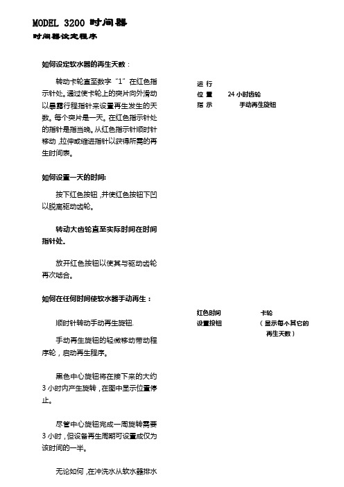
如何设定软水器的再生天数:转动卡轮直至数字“1”在红色指示针处。
通过使卡轮上的突片向外滑动以暴露行程指针来设置再生发生的天数。
每个突片是一天。
在红色指示针处的指针是指当晚。
从红色指示针顺时针移动,拉伸或缩进指针以获得所需的再生时间表。
如何设置一天的时间:按下红色按钮,并使红色按钮下凹以脱离驱动齿轮。
转动大齿轮直至实际时间在时间指针处。
放开红色按钮以使其与驱动齿轮再次啮合。
如何在任何时间使软水器手动再生:顺时针转动手动再生旋钮.手动再生旋钮的轻微移动带动程序轮,启动再生程序。
黑色中心旋钮将在接下来的大约3小时内产生旋转,在图中显示位置停止。
尽管中心旋钮完成一周旋转需要3小时,但设备再生周期可设置成仅为该时间的一半。
无论如何,在冲洗水从软水器排水管线流出停止后处理水可吸出。
运行位置 24小时齿轮指示手动再生旋钮红色时间卡轮设置按钮(显示每个其它的再生天数)注意!在盐箱中盐位必须总是高于水位。
如何设定软水器的再生天数:顺时针方向转动卡轮直至数字“1”与在固定中心盘上的黑色箭头相反,固定中心盘卡住卡轮。
当数字“1”旋至卡轮中相应于再生所需天数的再生用针时,从当天开始启动再生。
例如:图中显示再生用针插在卡轮中的数字3、6、9及12的位置,该设备将不会在当天(NO.1)再生,不会在下一天(NO.2)再生,而将在接下去的那天(NO.3)再生,并从那时起将每三天再生一次。
如何设置一天中的设备再生时间:放置一支圆珠笔或尖钉在带有一天时间数字的刻度盘上的任一孔中。
用笔或钉作为手柄在任一方向转动刻度盘直至所需再生时间与大齿轮上的点在一条线上。
图中显示设备设置再生时间于凌晨2:30,再生时间点在中心刻度盘早上部分的2和3之间。
如何设置一天的时间:按下红色按钮,并使红色按钮下凹以脱离驱动齿轮。
转动大齿轮直至实际时间在时间指示针处。
放开红色按钮以使其与驱动齿轮再次啮合。
在放松红色按钮后,确定驱动齿轮(位于红色按钮后)已完全与大齿轮啮合。
YAMAHA D3200 数字录音室操作指南说明书
D3200 - Digital Recording Studio FAQsHow do I export audio data to .WAV format on the D3200? How do I use and record with Session Drums on the D3200? How do I import audio from a CD into the D3200?How do I create an audio CD on the D3200?Exporting Audio Data to .WAV – D3200If you’d like to perform further edits or mastering to your recorded data via your computer/audio editing software, you will need to convert your tracks to the standard .wav format. Here’s how:1.Rewind the selected song to the beginning, either by pressing the rewind button, or by using the ClickPoint toselect the on-screen position locator and then rotating the value dial counterclockwise until the positionlocator shows “000.000.00”2.Press the STORE button3.Press the LOC1/IN button4.Play the song through to the end, or, use the ClickPoint to select the on-screen position locator and thenrotating the value dial clockwise until you’ve reached the end of the songNote: You can press the PLAY button to check your position from time to time. If you haven’t reached the end of the song yet, simply press the STOP button and keep scrolling through the song until you reach the end.5.Press the STORE button once again6.Press the LOC2/OUT buttonNow that you’ve supplied the “range” for what you would like to export (The points between the In location and the Out location). We can start the exportation process:7.Press the TRACK buttoning the ClickPoint, select the “Track Edit” tab on the bottom of the screenOn this screen, you will notice several parameters. The first, at the top of the screen, should indicate “CopyTrk (overwrite)”. You can leave this alone, since this is the function we’re going to use. The other settings are as follows:ing the ClickPoint, click the first location under “CopyTrk” to the left (source for the copy)ing the value dial, select the track(s) you’d like to exporting the ClickPoint click the second location, under “CopyTrk” to the right (destination for the copy)ing the value dial, select “Clip” (clipboard)ing the ClickPoint, click the “Exec” (execute) buttoning the ClickPoint, click on the “Export” tab at the bottom on the screening the ClickPoint, click “Drive”Here, you would choose to export the data to a CD, or, to the USB partition of the drive, which can be viewed over the USB connection. After you’ve selected and clicked “Yes” to confirm:ing the ClickPoint, click the “Exec” (execute) button17.When asked “Are you sure?” click “Yes”, and the export process will begin!Back to TopUsing and Recording the Session Drums – D3200The D3200 provides a pattern-based drum machine section named “Session Drums”. This can be a useful tool, as it provides backbeats to record to, as opposed to a standard metronome. Also, the patterns can be recorded and used as part of your song!To get the patterns to play:1.Press the SESSION DRUMS buttoning the ClickPoint, click “Run” on the screenAt this point, you can change things like variation, pattern and such to your liking. You can also chain patterns together to create an arrangement of patterns in other screens within the mode. While this gets into variants not easily covered in FAQ format, feel free to check the Session Drum section of the manual to see about all of the edits you can make!To record the patterns:1.Press the MIXER buttoning the ClickPoint, click on “CH Input/Sub-mixer”e the ClickPoint to choose the odd-numbers track that you want to designate as the left channel for thedrums (1, 3, 5, 7, etc.)ing the value dial set the track to the Drums Left icon. It will look like a small drum kit with “L” printed onthe kick drume the ClickPoint to choose the next even-numbered track that you want to designate as the right channel forthe drums (2, 4, 6, 8, etc.)ing the value dial set the track to the Drums Right icon. It will look like a small drum kit with “R” printedon the kick drum.7.Press the METER button8.Press the status buttons above the faders of the two tracks you previously dedicated to drums, so that theindicators are lit red9.Press the button above the “Drums” fader, so that the indicator is lit green10.Press the “REC” button, which will blink11.Press the “PLAY” buttonThe patterns will now be recorded and made into editable audio.Back to TopImporting From an Audio CD – D3200The D3200 can record from a standard audio CD onto desired channels. Here’s how it’s done:1.Insert the CD you wish to import track(s) from2.Press the CD buttoning the ClickPoint, select the CD Player Icon on the bottom right-hand side of the screening the ClickPoint, select the “>>” arrows to select the track you wish to recording the ClickPoint, select “CD IMPORT” at the top of the screenYou will be brought to a new window, which informs you that you should “Obey Copyright Rules” (... and of course you are – right?)ing the ClickPoint, select “YES”7.When the importation has been completed, using the ClickPoint, select “OK”You have now recorded the song as a Clip. Next, place it in a song:1.Press the TRACK buttoning the ClickPoint, select the “Edit Track” tab3.If not already selected on the screen, using the ClickPoint, make sure to select “CopyTrack” as the editoperationing the ClickPoint, click on the box above “Source”.ing the value dial, select “Clip2”, which accesses the audio CD data that has been importeding the ClickPoint, click on the box above “Destination”.ing the value dial, select “1-2”, which represents channels 1 and 2ing the click-point, on “EXEC” (Execute)You now have the tracks on the CD copied to channels 1 and 2 of the current song.Back to TopCreating an Audio CD – D3200This is a two part process. The first involves mixing your song down to the stereo Master Track. The second takes that mix on the Master Track and puts it onto the CD in such a way that it becomes a standard audio CD. Once your song sounds the way you want it to:1.Go to the beginning of the Song (000)2.Press the STORE button3.Press the LOC 1/IN button4.Go to the end of the song5.Press the STORE button.6.Press the LOC 2/OUT buttonYou’ve now set the range for the mix down. Now we’ll mix down:7.Go to the beginning of the Song once again8.Press the MASTER button until it is red in color9.Press the REC button10.Press the PLAY buttonLet the song play through, and the stereo mix of it will be on the Master Track. Now onto CD writing:11.Press the CD buttoning the click point, select “Album CD”ing the click point, select “Add”ing the click point, select the song on your list that you wish to burn to a CDing the click point, click on “OK”ing the click point, select “Write to CD”If you have more than one song mixed down, you can repeat steps 13 – 15 to add those songs, in order, to the CD prior to burning it.Back to Top。
3200中文设置手册教程

³ 999999 进入 / 退出编程
³ 901800 条码最短长度
条码长度锁定为 UPC/EAN 之外的条形码定义了特别的字符编号。首先扫描 进入 / 退出编程条形码开始设置,扫描条码长度锁定,然后扫描三个代码字 节表中的条形码代表期望设置的字符编号。例如,对于一个 12 个字符的条码 长度锁定,需扫描 0、 1、 2 三个条码。最后,再次扫描进入 / 退出编程条形 码进行保存。
³ 999999
进入 / 退出编程
³ 901900 条码长度锁定
代码字节
³
0
³
2
³
4
³
6
³
8
³
1
³
3
³
5
³
7
³
9
ASCII 转换图
十 十六
十 十六
十 十六
十六
十 十六
进制 进制 字符 进制 进制 字符 进制 进制 字符 十进制 进制 字符 进制 进制 字符
0 00 NUL 26 1A SUB 52 34 4 78 4E N 104 68 h
扫描 “ 进入 / 退出编程 ” 条码,即可开始。随后将 ASCII 字符的十进制等值 3 位数扫描到带代码字节条码的适当字符位置 (请参见代码字节,下页)。 若要保存,请再次扫描 “ 进入 / 退出编程 ” 条码。
示例:要添加星号 (*) 作为前缀,请扫描条码:
1. 进入 / 退出编程 2. 可配置的前缀 #1 3. 代码字节 0 4. 代码字节 4 5. 代码字节 2 6. 进入 / 退出编程
³ 999999 进入 / 退出编程
³ 903600 可配置的前缀 #2
³ 904600 可配置的后缀 #2
3200系列温控器说明书
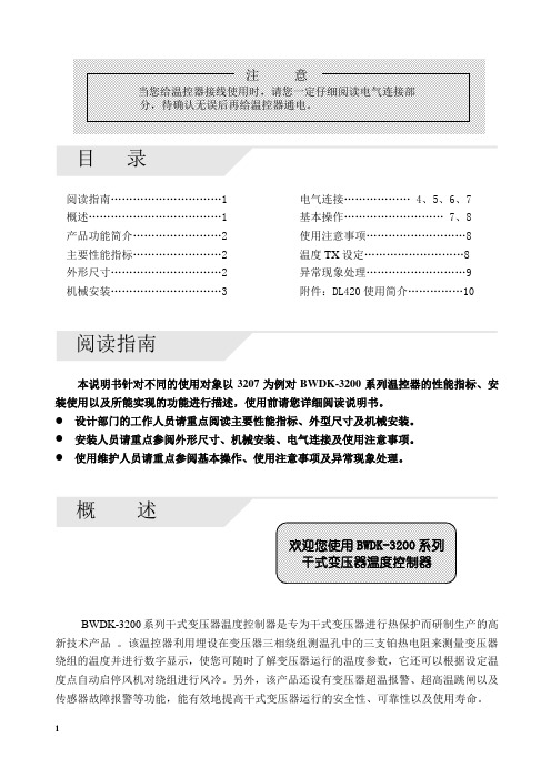
目录阅读指南…………………………1 电气连接……………… 4、5、6、7概述………………………………1 基本操作……………………… 7、8产品功能简介........................2 使用注意事项 (8)主要性能指标........................2 温度TX设定 (8)外形尺寸..............................2 异常现象处理 (9)机械安装..............................3 附件:DL420使用简介 (10)阅读指南本说明书针对不同的使用对象以3207为例对BWDK-3200系列温控器的性能指标、安装使用以及所能实现的功能进行描述,使用前请您详细阅读说明书。
●设计部门的工作人员请重点阅读主要性能指标、外型尺寸及机械安装。
●安装人员请重点参阅外形尺寸、机械安装、电气连接及使用注意事项。
●使用维护人员请重点参阅基本操作、使用注意事项及异常现象处理。
BWDK-3200系列干式变压器温度控制器是专为干式变压器进行热保护而研制生产的高新技术产品。
该温控器利用埋设在变压器三相绕组测温孔中的三支铂热电阻来测量变压器绕组的温度并进行数字显示,使您可随时了解变压器运行的温度参数,它还可以根据设定温度点自动启停风机对绕组进行风冷。
另外,该产品还设有变压器超温报警、超高温跳闸以及传感器故障报警等功能,能有效地提高干式变压器运行的安全性、可靠性以及使用寿命。
12产品功能简介主要性能指标正常工作环境温度:-10~+55℃ 控制误差:<±1℃相对湿度:5%~95% 显示方式:1位相位显示,3位半温度值显示 工作电源:AC220V ±10%,0.5A ,50Hz 外形尺寸(体积):263mm ×196mm ×85mm 测温范围:0~199.9℃ 最大功耗:10W测温精度:±0.5% 总重量:2.4kg外形尺寸前视图侧视图后视图3机械安装安装方式一:变压器本体安装安装方式二:变压器外壳安装图a 建议用安装支架结构图图b 安装后示意图图a 建议变压器外壳开孔尺寸图图b 安装示意图图c 安装后的位置图A.温控器铂电阻传感器的连接CA型铂电阻传感器电气连接图CB型铂电阻传感器电气连接图:B相B相45B .传感器的安装:安装步骤:1234传感器安装示意图C. 温控器端子排定义及接线1、3205端子排端子定义14 13 12 11 10 9 8注:1.1、2、3、4号端子空闲不用。
3200系列_中文手册
31ID 调节器 使用手册
目录
1.
1.1 1.2 1.3 1.4 1.4.1 1.4.2 1.4.3 1.4.4 1.5
2.
2.1 2.2 2.3 2.4 2.5 2.6 2.7 2.8 2.9 2.10 2.11 2.12 2.13 2.14
操作等级 2.............................................................................. 16
进入等级 2..........................................................................................................16 返回到等级 1 ..................................................................................................16
DTU柜DMP-3200说明书

智能配网终端智能配网终端产品(DTU)DMP2218型测控装置技术使用说明书南京磐能电力科技股份有限公司二零一一年五月用户手册V2.0感谢您选择使用南京磐能电力科技股份有限公司研发的DMP2218型配网自动化测控装置,为了方便您选购和安全、正确、高效的使用本终端,请仔细阅读本使用手册并在使用时务必注意一下几点。
注意CAUTION:◆该装置必须由专业人员进行安装与检修◆在对该装置进行任何内部或外部操作前、必须切断输入信号和电源◆始终使用合适的电压检测装置来确定仪表各部位无电压◆提供给该装置的电参数需在额定范围内下述情况会导致装置损坏或装置工作的异常:◆辅助电源电压超范围◆配电系统频率超范围◆电流或电压输入极性不正确◆带电拨通信插头◆未按要求连接端子连线◆废弃金属线头(丝)或其他金属物体遗留在机箱中,导致短路本手册可以在本公司的主页上下载到最新版本,同时也提供一些相应的测试软件下载。
如果您需要纸质用户手册可以向本公司的技术服务部门申请。
关于本装置的所有技术说明书和技术资料的版权为南京磐能电力科技股份有限公司所有,公司保留对所有资料的修改和解释权。
智能配网终端目录1.装置概述 (2)1.1.引用标准 (2)1.2.DTU终端测控装置选型说明 (3)1.3.DTU测控装置结构 (4)1.4.主要技术特点 (6)1.5.主要功能 (7)2.技术参数 (8)2.1.额定参数 (8)2.2.主要技术性能 (9)2.3.抗干扰性能 (9)2.4.绝缘性能 (10)2.5.机械性能 (10)2.6.环境条件 (11)3.装置硬件 (11)3.1.机箱结构 (11)3.2.主要插件 (12)4.系统信息说明 (13)4.1.定值整定信息 (13)5.典型应用 (14)5.1.环网柜应用 (14)5.2.配电房应用(节能监测) (14)5.3.配电房应用2----低压环网配电。
(15)6.调试及异常处理 (16)6.1.调试注意事项 (16)6.2.装置通电前检查 (16)6.3.绝缘检查 (16)6.4.上电检查 (16)6.5.采样精度检查 (17)6.6.遥信输入检查 (17)6.7.继电器接点校验 (17)6.8.跳合闸电流保护试验 (17)6.9.异常处理(见表9-1) (17)7.投运说明及注意事项 (17)8.贮存及保修 (18)8.1.贮存条件 (18)8.2.保修时间 (18)9.供应成套性 (18)10.随同产品一起供应的附件 (18)11.订货须知 (18)附图一能终端机箱尺寸及布置图(16路) (20)附图二智能终端机箱尺寸及布置图(10路) (21)DMP2218型技术使用说明书1.装置概述DMP2218型智能配电测控装置(以下简称装置),可用于10kV及以下电压等级的中性点不接地、经消弧线圈接地或经小电阻接地系统中馈电线路测控需求。
TASCAM -DM3200(中文说明书)

通道目的地 这里有 16 条总线,8 条辅助总线,
16 路可用插入,还有立体声总线模块。通道的输 出可以分配到这几处。
可用的物理输出包括内置的 TDIF 输出,8 通道 ADAT 光纤,两路立体声数字和一路立体声模拟 输出。
带 EQ 功能的 32 路通道有两种信号来源(input 和 return),这两种信号源可自由分配,可接通和 关闭,不管项目是否在记录或追踪阶段。请看分 配部分(46 页“Routing & assignment”)有关怎样 分配通道信号源的细说。
图 1.1:DM-3200 基本逻辑成分 a a.. 注意串联连接在 DM-3200 的最初版本中不可用。
数字方面包含 3 个 TDIF I/O 端口,ADAT“光纤” I/O 端口,两对立体声 S/PDIF 或 AES/EBU 输入和 输出。
两块 TASCAM 标准卡槽提供 I/O 的扩展容量,带 有多种可用的数字或模拟选项,包括 FireWire 扩 展卡提供的 DAW 和 DM-3200 之间的高速双向通
此外,即使工作在 88.2kHz 或 96kHz 的取样频率, DM-3200 仍保持通道和设备相同的数字如同运行 常规的取样频率。
输出 输出信号源(内置的和可选的插槽)被分
配到实际的物理输出。
自总线输出可以被分配到 TDIF 和 ADAT 端口后, 就允许录制混合环绕的全部的通道。
选项卡槽提供输出如同输入那样。
效果
DM-3200 集合了两个高品质数字效果器,包括一 个 TC Works 的数字混响程序。
信号可在内部通过总线或 aux 辅助送出分配到效 果器,返回信号在混合时把信号反馈到混合器通 道。作为选择,可分配的插入可用来插入和实现 进入通道模块的信号路径。
TASCAM DM-3200 DM-4800数字混音台说明书

222M COMPATIBLE TASCAMDM -3200/DM -4800 DIGITAL M IXERS The DM-3200 is a 32-chan-nel digital mixing console, even at its full 96kHz/24bit audio resolution. It features48 inputs at mixdown consisting of 16 analog mic/line inputs with analog inserts,24 channels of TDIF and 8 channels of ADAT built-in, with EQ and compression oneach channel. It has 16 mixing busses, 8 aux sends, 4-band fully-parametric EQ anddynamics on every channel, and 4 effects processors. It mixes in surround, panningup to 6.1 output channels, and the optional IF-SM/DM expansion card adds surroundmonitoring and downmixing. An additional expansion card, the IF-FW/DM FireWirecard, turns the console into a 24-channel computer audio interface, making it acomplete studio solution for professional DAW recording. It has 2 expansion cardslots to support optional FireWire, surround monitor, ADAT, AES/EBU, Analog, TDIFcards, Aviom A-Net, and CobraNet. DAW and transport machine control is standard.The DM-4800 has a 64-channel mix platform with a “fat channel” strip in the center ofthe board, providing instant access to 4-band parametric EQ, dynamics and aux con-trols available for the first 48 channels. It features 24 mic preamps and a completelyconfigurable 24-buss routing system.ITEM DESCRIPTIO N PRICEDM3200.....................32-channel digital mixer .................................................................CALLDM4800.....................64-channel digital mixer .................................................................CALLOptional AccessoriesMU1000.....................Optional meterbridge for DM3200 or DM4800 .................................CALLIFFW/DM-MKII ..........FireWire interface card ....................................................................CALLIFAN/DM ....................8-channel balanced analog card ....................................................CALLIFTD/DM ....................8-channel TDIF digital card ............................................................CALLIFAE/DM ....................8-channel AES/EBU digital card .....................................................CALLIFSM/DM ...................Surround monitor card ....................................................................CALLIF-AV/DM ...................Aviom A-Net® Interface Card .........................................................CALLIF-CB/DM ..................CobraNet® Interface Card ..............................................................CALLPW1000CS ................Cascade cable for DM3200 .............................................................CALL (DM4800 / METER BRIDGE OPTIONAL)SYMETRIX ZONE MIX 760 Paging and music management for venues like restau-rants, bars, clubs, retail and more. Features 12 inputs (4 mic, 8 line), 6 outputs, com-pression, AGC, matrix mixing, paging, feedback elimination, filters and equalization. Set-up uses a straightforward Windows interface connected via Ethernet. Remote control isachievable with the Symetrix ARC-2I adaptive remote control wall plate. The ARC-2I is amenu-driven remote control with 24 menus, each with up to 16 enumerations that canbe used to control basic functions or initiate complex logic-based control events suchas gain, preset triggering, source selection, room combining and more.ITEM DESCRIPTIO N PRICE760............................Zone mixer, 12 inputs ...............................................................1239.00ARC-2I ......................Adaptive remote control wall plate ..............................................199.00WHIRLWIND M IX-5S All-purpose mixer for sound con t ract i ng. Offers 4 inputchannels, each with XLR and 1/4" TRS balanced con n ec t ors, suitable for mic or line-level use. An LED readout provides a visual in d i c a t ion of levels, and phantom poweris provided for operating condenser mi c ro p hones. XLR and 1/4" TRS outputs areprovided, with the XLR output mic or line level swit c h a ble. The outputs have theirown drive-circuit for isolation. An aux channel is pro v id e d with RCA input jacks forconnecting a tuner, CD player, tape player, etc.ITEM DESCRIPTIO N PRICEMIX-5S ......................Stereo mixer ................................................................................379.07MIX-5 ........................Mono version of MIX-5S ...............................................................336.898 SERIES LIVE The Yamaha log 8-group consoles with lots of features, great performance and quality sound. Each mono input223compact console package thatincludes Yamaha’s unsurpassedIXING STUDIO MW10C5D DIGITAL LIVE in two versions, the microphone preamps on the standard PM5D224AHA LS9 DIGITALExpandable digitalpact and lightweight frame with16 mono-input/4 stereo-inputconfiguration (LS9-16) or in thelarger frame, high-input capacity (LS9-32). With 32 input head amps for mic or line levelinputs plus 4 stereo inputs, the LS9-32 can comfortablyhandle the complex and varied source requirementsfor live sound applications. Both models can doublethe mono input capacity, expanding to 32 (LS9-16) orYGDAI interface cards. They have motorized 100mmlong-throw faders and a versatile bus architecture withLS9-16LS9-32M7CL-32M7CL-48AVY16-ES100MY8AD24MY8AE96S MY8AEB MY8DA96MY8AE MY8AD96MY8AE96MY16AE MY16AT MY16-CII MY16ES64MY16MD64YAMAHA CARDS FOR DIGITAL MIXERS ITEM DESCRIPTIO N PRICE AVY16-ES100 .......16-channel Ethersound network I/O card, RJ45 ....................................CALL MY4AD ..................24 bit 4-channel input card – XLR .......................................................CALL MY4DA ..................20 bit 4-channel output card – XLR .....................................................CALL MY8AD24..............8-24bit analog inputs on balanced 1/4" connectors ............................CALL MY8AD96..............24 bit/96kHz 8-channel line level analog input card (25-pin D-sub) ......CALL MY8ADDA96 .........8-channel analog I /O ............................................................................CALL MY8AE ..................8 AES/EBU digital format I /O (25-pin D-Sub) .......................................CALL MY8AE96..............24 bit/96kHz 8-channel AES/EBU digital I /O card (25-pin D-sub) ........CALL MY8AE96 ..............24 bit/96kHz 8-channel AES/EBU digital I/O card w/sample rate converter (25-pin D-sub) ...............................................CALL MY8AEB ................8-channel AES/EBU I/O card w/video input on BNC ..............................CALLMY8AT ..................8 ADAT digital format I /O (optical connectors) .....................................CALL MY8DA96..............24 bit/96kHz 8-channel line level analog output card (25-pin D-sub) .......CALL MY8-SDI-D ...........1-channel/8-multiplex 24bit HD/SDI card, w/2X BNC ...........................CALL MY8TD ..................8 TDI F digital format I /O (25-pin D-Sub) ..............................................CALL MY16AE ................16-channel AES/EBU I /O card ...............................................................CALL MY16AT ................16-channel ADAT I /O card .....................................................................CALL MY16-CII ..............16-channel Cobranet network I/O card .................................................CALL MY16ES64 ............16-channel EtherSound network I/O card, 2 Ethercon,9-pin HA remote, and 2 RJ45 cascade. Use with up to3-MY16EX cards to increase I/O to 64. .................................................CALLMY16EX ................16-channel I/O expansion card for use with MY16MD64 or MY16ES64,has 2 RJ45 cascade, uses standard CAT5 cables for interconnect ..........CALLMY16MD64...........16-channel MADI I/O card, 2-BNC, 2 optical MADI, & 2 RJ45 cascade.Use w/up to 3 MY16EX cards to increase I/O to 64. ..............................CALLMY16TD ................16-channel TDI F I /O card ......................................................................CALLLightViper fiber optic system interface cards for YGDAI-compatible Yamaha consolesVIMMY32M-T4 ......Interface card with TAC4 fiber connector ........................................1609.00 VIMMY32M-OC .....Interface card with Neutrik OpticalCon fiber connector ..................1015.00VIMMY32M-LC ......Interface card with LC fiber connector ..............................................899.00VIMMY32-S ..........Slave card, no fiber connections .......................................................740.00VIMMY32M-ST ......Interface card with ST optics ............................................................934.00Please visit the LightViper Digital Optical Snakes Systems section for more information and compatible gear.WAVES WSG-Y16 SOUNDGRID I/O CARD FOR YAMAHA MIXING CONSOLES Waves SoundGrid is a new audio networking and processing platform that delivers high precision with low latency. The WSG-Y16 brings cutting-edge SoundGrid technology to Yamaha mixing consoles. Together with a server, a Mac or PC, and iLok authorized Waves plug-ins, the WSG-Y16 lets you process 16 channels of audio using Waves award-winning plug-ins (in conjunction with Waves Multi-Rack software) directly from a Yamaha console. Features include redundancy and recovery safety net, MIDI control from the console, plus scalablilty and expand-ability, make this card indespensible to any compatible Yamaha console. Supports 44.1/48/88.2/96kHz sample rates (44.1 & 48kHz for 16 channel processing) and tranmits via Ethernet.ITEM DESCRIPTIO N PRICE WSG-Y16 ...................Mini-YGDAI SoundGrid I/O card ...................................................640.00Tenemos ventas y servicio en Español.Expertos que hablan Español disponibles en x1178 y x1164.Honesty and Valuesince 1971。
TD3200变频器用户手册(中文)
D3200 D3300系列快速网络指南说明书
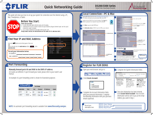
1 Find Your IP and MAC Address
Press the button on the front panel of the DVR. OR Right-click and click the Main Menu button ( System>Info.
), then
Record your information below:
Password: Enter DDNS Device Password.
Click Apply to save your settings.
NOTE: It may take between 10~15 minutes for the DDNS server to update with your new DDNS address.
f
Record your information here:
DDNS User Name: DDNS Domain Name: DDNS Password:
D3200/D3300 Series Quick Network Guide - English - R5
Quick Networking Guide
6 Connect Over the Internet—PC & Mac
a Install CMS-D3 from the CD or from /pro on a PC or Mac on a different network than the DVR.
b Double-click the CMS-D3 icon from the desktop. Click Login (by default a password is not required to log into the software).
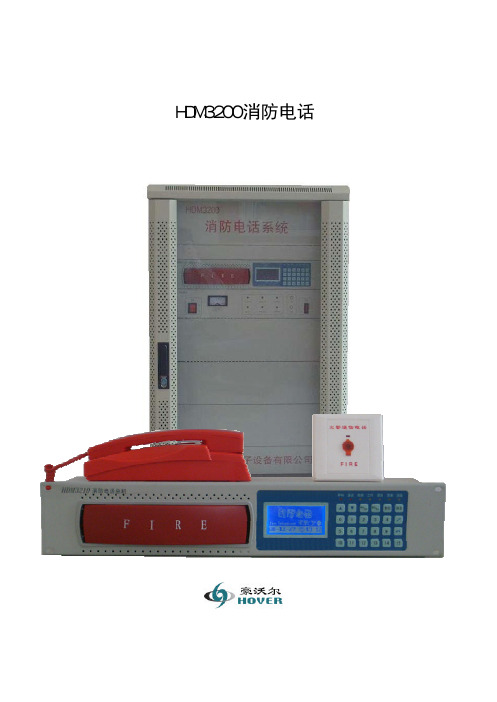
HDM3200消防电话使用说明书
HDM3200消防电话使用说明书北京豪沃尔电子设备有限公司 注意事项前言注意:用户在安装、使用产品前,请阅读本说明书以及机器上标明的所有警告及说明事项。
如果您遵从以下有关安装、使用以及保养步骤,系统会处于良好工作状态。
本机是完全集成化的装置,并无用户可以修理的部件。
一概述感谢您选用我们的HDM3200消防电话系统。
HDM3200消防电话系统是为适应用户的不同需要,并严格按照国家标准GB16806-2006设计开发的一款采用二总线技术的新型消防应急通讯产品。
是广泛应用于建筑物及公共场所内消防控制系统中的重要通信设备。
HDM3200消防电话系统包括HDM3210消防电话主机,HBM1001消防电源以及备用电池组成。
HDM3210消防电话总机可接入HD312台壁式消防电话分机、HD322消防电话插孔以及和它配套的HD220插孔式消防电话分机,构成完善的消防应急通信系统,适用于建筑内发生火灾或紧急情况时与中心控制室通讯、调度。
当应用现场出现紧急情况时,现场人员通过本系统快速与中心控制室取得联系,或中心指挥系统由其它系统得到紧急信息,通过火警广播通信系统调度指挥现场,通过广播快速指挥或疏散人员。
为使用户尽快熟悉和正确使用该设备,针对本系统编制了这本使用操作说明书。
1. HDM3200消防电话采用四门式标准机柜,侧门可拆卸,便于安装调试。
前面为超大钢化玻璃门,方便系统监控,前后门均配有门锁,防止误操作。
2. HDM3210消防电话主机使用标准直流24伏供电,前面板镶嵌电话座整体注塑件结构,轻触式按键,数字键盘输入,人性化操作,大型液晶显示屏,蓝色背光显示,实时时钟显示,美观大方、线条流畅。
给使用、安装和维护带来了极大便利,具有结构紧凑、安装方便、通用性强、使用灵活、应用范围广,可靠性高等特点。
3. HDM3210消防电话主机与分机HD312、HD322、HD220组成电话系统,可应用于建筑物内紧急情况下的语音通信。
3200使用说明书

(1) Function mode: Displays the currently selected display (Spectrum, Bar graph, and Counter)(see page 23)(2) Scan mode: Displays the selected scan mode.3 types of scanning may be selected. See page 14 and 26 for manual scan, pages 17& 26 for search and pages 16 & 26 for channel scan.(3) Title name: The data memory, which is, selected (page 37)(4) Marker Frequency: The frequency in which the unit is currently tuned to as indicated by the marker indicator.(5) Ref.Level: The base line reference amplitude(0 level). The Reception modes (page 50)or the selected external Attenuator value (page 46)sets this value.(6) Marker Level: The amplitude value of the signal level the unit is currently tuned to as indicated by the marker.(10) Reception Mode: The type of modulation needed for aural reception of the incoming signal.Note: a CW or a signal other than a Narrow Band FM(NBFM),wideband FM(WBFM), AM or SSB may be displayed by selecting a reception mode which has the appropriate bandwidth(see page 5).button.(11) Sweep Mode: Determines how the scan moves across the screen when the squelch is activated.(See page 26)(12) Displays the value of the squelch level (see page 51).(13) Marker: Indicates the signal level currently being scanned(14) Attenuator Value: Displays the amount of external attenuation connected to the input. Whenan external Attenuator is used, the value of the Attenuator must be added to the Reference level. This is accomplished through the ATT dB set in the systemCONTENTSQuick Main Menu set up guide (ⅰ)Quick System Menu set up guide (ⅱ)Function Key Menu guide (ⅲ)Display Description (ⅳ)Ⅰ. Introduction (4)1. General (4)2. Features (4)Ⅱ. Specifications (4)Ⅲ. Precautions (7)Ⅳ. Functional Description (9)1. Panel Description (9)Ⅴ. Basic operation (12)1. General (12)1 Prior to connecting to a power source (12)2 Input connection (12)3 Powering the unit on (12)4 Entering a Frequency value (13)5 Scanning (13)6 Positioning the Frequency marker (14)7 Power Off (14)2. Manual Scan (14)3. Ch. Memory Scan (16)4. Search Scan5. Difference Mode6. Frequency Counter7. Recorder Mode8. Power supply1 Car and AC adapter2 Battery Replacement Ⅵ. Menu Description1. The Main Menu1 Main menu display2 Function Modes3 Scan Modes4 Sweep Mode5 Edit Channel 5-1 Selecting Edit Channel 5-2 Assigning a Channel number 5-3 Entering a Channel name5-4 Insert Function5-5 Delete Function1-6 Setup Memory6-1 Setup Memory6-2 Save and Load setups 6-3 Title Names1-7 Data Memory 7-1 Data Memory Setup 7-2 Saving and Loading7-3 Title name ....................................................................................17..............................................................................19...........................................................................19.................................................................................21....................................................................................22........................................................................22........................................................................22....................................................................................23.................................................................................23...........................................................................23..............................................................................23....................................................................................26....................................................................................27 (28) (28) (30)............................................................30...........................................................................32...........................................................................32.................................................................................32..............................................................................32.....................................................................34....................................................................................35 (37) (37)........................................................................38 (38)8 SSB BFO9 Hold Mode10 Level Hold 2. The System Menu1 System Menu display2 db Unit3 Power Off4 I/O Menu5 Printer Menu6 Copy Set Mode7 External Attenuators 8 Test Set Menu9 SCRB Menu10 Battery Check 11 Keyboard Buzzer 3. Function Keys …………1 RUN2 STEP3 MODE4 SQL (Squelch Level)4. LCD Men …………u 1 LCD Contrast2 LIGHT 3 GRID 4 PRINT ........................................................................................................ 39..........................................................................................39.. (41)....................................................................................42...........................................................................42............................................................................................... 43........................................................................................... 43............................................................................................ 44........................................................................................ 44....................................................................................45...........................................................................46.................................................................................47....................................................................................47.................................................................................. 48 (48)................................................................................ 49.............................................................................................. 49................................................................................................49. (50)............................................................................ 51.......................................................................................51.................................................................................51................................................................................................52...................................................................................................52 (53)I. INTRODUCTION1. GeneralThe 3201 is the world’s first hand-held RF Field Strength Analyzer.With a wide band reception range of 100 KHz to 2060MHz, the 3201is a compact and Lightweight portable analyzer. It is the ideal tool for field RF technicians to test, install and Maintain Mobile Telecommunications Systems, Cellular and Cordless Phones, CB Radios, Paging Systems, Cable and Satellite TV systems as well as antenna site measurements and Maintenance.2. Features•100KHz to 2060MHz measurement range•Measures and demodulates Narrow Band FM(N-FM), Wide Banc FM(W-FM),AM, Single Side Band (SSB) signals.•Built-in 2GHz Frequency Counter.•PLL tuning system for precise frequency tuning.•Up to 160 channels may be scanned and displayed on the LCD•Built-in Speaker•192 X 192 pixel backlit LCD•All functions are menu selectable•Has a RS-232 and parallel interfaceII. SPECIFICATIONSReception FrequencyFrequency range Freq. Accuracy (TXO) Freq. Accuracy (display) DemodulationStep frequencyData memorySet Up memory Reception sensitivityScan spee : 100KHz to 2060MHz: ±3PPM: ±25PPM: N-FM, W-FM, AM, SSB: 5KHz to 9995KHz in multiples of 5KHz and 6.25KHz: Stores 10 displays of up to 160 Channels per display(1600) : Stores 10 setups for each scan mode: Approx.0 –6 dBµEMF.(S/N: 12dB at N-FM, 10dB at W-FM): 12.5Ch./sec.max.dInput impedanceMax.Input voltageAudio output Level MeasurementN-FM mode RangeResolutionAccuracyRepeatabilityBandwidthW-FM/AM/SSB RangeResolutionAccuracyRepeatabilityBandwidth Spurious and Noise Level internally generated : 50Ω(standard): Max. 5V RMS : 120mW into 8Ωspeaker: -70 to –20dBmV(-10 to 40dB µV)for 300 to 1800MHz -60 to –20dBmV(0 to 40dB µV)for 1 to 300MHz and 1800 to 2000MHz : ±0.5dB µV : ±3dB(at an ambient of temperature of 23℃±3℃): ±2dB : Approx. 12.5KHz(-6dB): -60 to –10dBmV(0 to 50dB µV)for 300 to 1800MHz -50 to –10dBmV(10 to 50dB µV)for 10 to 300MHz and 1800 to 2000MHz : ±0.5dB µV : ±3dB(at an ambient of temperature of 23℃±3℃): ±2dB : WFM: Approx. 180KHz(-6dB), AM/SSB:Approx.2.4KHz(-6dB): -35dBc W-FM: -45dBc for N-FM typical, below a full scale signal level frequency.FunctionsDisplay modes Sweep modesScan modesHold modesLevel hold modesSquelch function Copy function : Spectrum displayMulti Bar graph display(5, 10, 20, 40, 80, 160CH)Single Bar graph displayDifference frequency displayFrequency measurement level display: Single, Normal, Free Run, Free Single : Manual, CH.Memory and Search scan : Delay run, Delay hold and delay stop : Max. Hold, Hold, 40mS, 100mS and 200ms peak hold : Squelch level is displayed as a bar graph and a digital Readout. Thesquelch level may be adjusted to any value from the reference level to Full scale: The copy set mode allows the contents of the Channel edit, Setup andData memories to be copied to an external device. Data may also be written in to these memories from an external device.Frequency CounterFrequency range No. of digits Resolution Accuracy Sampling time Input sensitivityInput impedance Max.Input voltage Data memory : 9MHz to 2060MHz: 7 digits: 1KHz:±50 PPM ±1 count: 0.512sec.: 9MHz to 2000MHz: 150mV RMS 20MHz to 1000MHz: 100mV RMS : 50Ω: 5V RMS Max.: 10 readings may be storedMiscellaeous SpecificationsLCDBack lightRS-232C Interface Power sourceAuto Power Off : 192 X 192 pixels green, Led backlit: Back light will shut off 5 seconds after the last key depression or continuously on may be selected: 1200, 2400, 4800, 9600 BPS(8 Pin Mini Din): (6)1.5V AA type NICD batteries 11V to 16V 400mA Max.AC to DC adapter, 12VDC car adapter: Unit will shut off after 5, 10, 20 or 30 minutes of idle time,menu selectable.Physical specificationsOperating Temperature & Humidity Storage TemperatureDimensionWeight : 0℃to 40℃at 35-85% RH: 10℃to 50℃: 4”(W) x 9”(H) x 1.77”(D): Approx. 1.4Ib(including antenna)Std AccessoriesCoaxial cable, earphones, Antenna (receiver only), (6)AA NiCd batteries RS232C cable, carrying Case carrying strap, Vehicle power adapter, AC/DC adapter, operators manualOptional accessories: Parallel printer cable and PR-232C mini printerIII. PRECAUTIONSStorageDo not store this equipment in:•Direct sunshine, near heating devices or in an automobile in the summer time.•Locations with high humidity and poor ventilation.•Dusty or smoky environments.•Extremely low temperature.Handling•This product is a sophisticated electronic device, do not:Service or perform adjustments.•Do not apply great force to the keys and switches.Be sure the slide switch inside the battery cover is set to the right Position, If alkaline batteries are used set the switch to right (dry position). If NiCd batteries are being used set the switch to the left (NiCd position)Warning: If the switch is in the NiCd position when alkaline batteries are used may cause these batteries to over heat, explore or leak.AntennaDue to the broad applications of this unit, the supplied antenna is for the 800MHz cellular band. It may be necessary to use a different antenna more appropriate for your application.The receiving conditions vary with location and antenna. On some occasions, it’s not possible to receive the desired signals due to strong Interference from other electronic sources such as broadcast stations.Connecting to other devicesWhen connecting this unit to other devices (CATV cable etc) be sure that the measured system voltage is not greater than the maximum input voltage. Use attenuators to preventthe input voltage from being overloaded by higher than the rated input voltage(5V rms).If the input voltage is greater than the rated input voltage of this unit, possible damage may result.Be sure that the external DC input jack is the correct polarity.The DC jack tip must be positive in respect to ground.If the unit is not functioning correctly or “locked up”when the power is turned on perform the following procedure:•Press the power button to shut the power off•keys simultaneously. This will clear the internal memory and return the unit to normal operation.Note: An alternate method to clear a malfunctioning unit is to select ALL RESET from Test set menu located in the system menu.IV. FUNCTIONAL DESCRIPTION 1. PANEL DESCRIPTION1). Signal level input connectorConnect to the Antenna or Coax cable. Maximum input Voltage is 5 Volts.2).Frequency counter inputConnect to the signal source to be measured. Maximum input voltage is 5 Volts.3). Volume controlAudio output Volume control. To increase the volume, rotate the Volume control clockwise.4). Earphone Jack5). Attenuator ““(Pushed in) Inserts 10dB of attenuation into the Signal level input. Used in the presence of noise or very strong signals.““(Pushed Out) No attenuation6). LCD (Liquid Crystal Display)Displays the Signal levels, their characteristics (frequency, amplitude, etc) and pertinent system data.7).Press this button to turn the power on. Press again to turn the power off.LCD menu items consists of LCD Contrast control, LCD Grid select, Backlight and Print command. These items arekeys.9).key a 3rd time returns the LCD to the signal level displays.10).This key enters the menu item you have selected or the numeric values you have enteredform the keyboard.These keys select: Run, Step frequency menu, Reception modemenu, and squelch Level.These keys are located at the bottom of the LCD display. They also are used to select the itemskey will enter a negative13). This key is used for entering decimal points. If a decimal point is already entered, this key isthen used for clearing a keyboard entry.14).This key is used for incrementing and decrementing the Market frequency and for selecting items in the various menus.15).Rotary Dial Knob) but at a faster rate.The rotary dial knob allows one-handed operation.16). DC Input Jack The AC/DC adapter and cigarette lighter adapter connect to this input for applying DCPower to the unit from an external source.17). RS-232C Connector(8 pin mini DIN connector)This connector is used for interfacing to a personal computer or a printer.18). Belt ClipFor attaching the RF-3201 to your belt.19). SpeakerFor listening to the demodulated output of a RF carrier signal level.V. BASIC OPERATION1. General1 Prior connecting to a power sourceSee page 22 for inserting batteries, battery charging and connecting to a power source.2 Input connectionConnect the antenna or coax cable to the BNC input marked ANT if measuring a RF carrier signal level. If measuring a frequency connect the coax cable to the Frequency counter input.Note: Do not exceed 5V rms3 Powering the unit on[2] The welcome screen will be displayed followed by the last screen that was displayed prior toshutting the power off.[4] See the graphic below for a description of the LCD display when powered on.[5] Adjust the volume control for an appropriate sound level. If the signal level is belowthe squelch level there will be no output sound from thespeaker.key to quit.4 To enter a frequency value[1] The selected scan mode is displayed in the top center of the LCD. In the above,example manual scan was selected. The frequency entered from the keyboard in thiscase is the is the center frequency and is the frequency indicated by the market.Note: in order to enter a frequency from the keyboard scanning must be halted.Example1: To enter 100.00625MHz from the keyboard: Press the following key sequence:Example2: To enter 500KHz press the following key sequence:Note:but if the decimal point has[3] The frequency value has different functions for the Manual, Search and Cannel scan.The entered frequency in manual scan sets the Center frequency where as the entered frequency values in search scanning sets the Start and stop frequencies.In the Channel scan mode the entered frequency value is stored along with its channel name in the Channel memory (see page 28 through 30). This will be used for scanningpreviously stored scans along with their channel namesand frequency.5 Scanningicon and the scanning will start.[2] If Free Run sweep is selected from the Sweep menu scanning will be continuous andkey a second time will stop the scanning.[3] When Normal Sweep has been selected the scan will halt when the signal level value isgreater than the squelch level. Scanning will resume when the signal level value dropsbelow the squelch level.[4] When scanning is halted the marker will indicate the signal level and display theamplitude value on the LCD.6 Positioning the Frequency Marker indicatorwhen the scanning has been halted can be used to position the marker frequency indicator over asignal level in order to find it’s frequency andsignal level amplitude values.7 Power Offfinished.Note: When the unit is powered-on again, the screen prior to powering off will be displayed.2. Manual Scan Mode[1] when Manual scan mode is selected, It is necessary to enter the following information:a) The Center frequency value from the keyboard,menu.c) The Frequency Span which is set by the Step frequency. The Frequency span isdetermined by the number of channels per displayed (Selected from the function menumultiplied by the step frequency. See the 2 examples below on how the frequency spanis determined by the step frequency.Example 1: To set a frequency span of 8MHz using the Spectrum display mode a stepfrequency of 50KHz is required(160 x 0.050MHz = 8MHz).Example 2: If a 40 Bar graph display is selected and the step frequency is 100KHz theFrequency span is 40 x 0.1MHz = 4MHz.[2] To select the Manual scanning mode press the following key sequence:(Select the Scan menu) (Select Manual Scan mode)[3] The center frequency, Span, Step Frequency and reception mode are displayed in the lowerpart of the LCD.Note:The frequency span is not displayed in the 2 channel difference, Single or counter modes.[4] To enter the Center/Market frequency the unit must not be Scanning (Run icon not highlighted)(See pages 12 and 13)[5] When the scanning is stopped the Market frequency indicator may be positioned over akeys or rotating the dial knob.The position of the market may be moved by up to 160 channels.(+80 channels to –80 channels)In the 2-channel mode the market/center frequency and the difference frequency are scanned and displayed.Note:Scanning is not available in the signal channel or counter mode.[7] You can save 10 displays of up to 160 channels and their setups by storing them in the Dataand setup memory. These may be selected from the main menu.(see pages 32 through 38)[8] Example of a manual scan display3. Ch. Memory Scan[1] Names and frequencies of signal levels of interest may be entered and stored in thechannel memory prior to scanning. When scanned these signal levels will be displayedalong with their frequencies and name.Ten displays of up to 160 signal level Channels per display(1600 channels total) may beentered, edited and stored in the channel memory (See pages 28 through 30)[2] To select the Channel scan mode press the following key sequence.(Select Scan Mode) (Select Chan.Scan)[3] The LCD will display the current signal level frequency as indicated by the marker, thesignal amplitude, and the channel name displayed at the bottom of the LCD.[4] A signal level frequency may also be entered in to the channel memory from the keyboard(see page 12 for entering frequencies).The type of reception (demodulation) must also be selected(see page 48).The step frequency will be indicated but is not used for the Channel scan mode.the left most position (The RUN icon is highlighted).frequency indicator and display the amplitude, frequency and name of the signal levelsdisplayed on the LCD. The market indicator may be moved up to +80 channels to –80channels from its present position.Note:Scanning is inoperative in the Single scan and counter modes.In the Difference mode only the Market and the difference frequency is scanned and displayed.[7] A stored display in the Data memory may be scanned and displayed in the channel scanmode. The set up memory in this case is used for selecting the stored display to be scanned.[8] Example of a channel scan display:4. Search Scan[1] Search scan is the scanning between a start stop frequency, which are entered from thekeyboard.[2] To selected the scan mode enter the following key sequence:(Select the Scan menu) (Select search Scan)[3] The START, STOP, STEP frequencies and the reception mode (demodulation type) willbe displayed at the bottom of the LCD with the start frequency highlighted.[4] Enter the START FREQUENCY from the keyboard. This frequency will now be displayedas the start frequency and at the market frequency indicator (See page 12).When the START frequency is entered, STOP FREQUENCY will be highlighted.Enter the STOP frequency from the keyboard.Note ;scanning must be stopped before entering the START and STOPfrequencies.frequency indicator at the step frequency increment to different positions depending on which key is pressed or which direction the rotary dial is rotated.Marker frequency indicator will update at the step frequency increment until it reaches the STOP frequency. When the stop frequency is reached the scanning will start over at the start frequency if Free Run or Normal sweep was selected or stop if Free single or single sweep was selected.signal where the Marker frequency indicator halted will be displayed.[8] If the Scan mode is changed to Manual Scan the frequency where the marker halted(in step 7) will become the center frequency.[9] You can save 10 displays of up to 160 channels per display and their setups by storing themin the Data and setup memory in the main menu. (See pages 32 through 38)5. Difference modeScans and displays 2 signal levels in which one signal level frequency is entered from the Keyboard and the other signal level is at a difference frequency selected from the step Frequency menu. The amplitude of each is displayed as a bar graph on the right side of the Display along with their signal difference.This feature is useful for measuring the difference in amplitudes between the video carrier And audio carriers of a TV signal or measuring the variation in amplitude of a transmitted Signal at different locations[1] To select the 2 channel difference mode press the following key sequence:(Select the Function mode) (Select 2 channel Difference)[2] Enter the marker frequency to be measured from keyboard.[3] Select or enter from the keyboard the difference frequency to be measured form the step[4] The LCD will display the bar graphs of the marker frequency and difference frequency amplitudes. The difference amplitude between the two signal levels will also be displayed.6. Frequency Counter The frequency counter may be used to measure and record unknown frequencies[1] To select the frequency counter press the following key sequence (select Function) (select counter)[3] Connect the signal source output to the counter input Note : Maximum input voltage is 5Voltssignal is measured, is frequency value will be stored in the data memory starting at frequency position #1 (see page 38).If the input frequency values changes the new frequency value will be stored insuccessive positions until all 10 positions are written. Additional frequencies will then displace previously stored frequencies starting with the 1position.will be the displayed at the marker indicator [6] A frequency stored in the counter data memory may be recalled by selecting the desiredused as the center frequency when set to the manual-scanning mode.Difference Display (Pg. 19) Counter Display (Pg. 19)7. Recorder functionThe 3201 may be used to display and record (store in memory) trends and variations of a Signal level as a continuous pattern of bar graphs. This feature is convent if the amplitude Variations of a signal level under test need to be monitored over a period of time.To set the Recorder mode use the following procedure:[1](Select the Scan menu) (select Manual or search scan)[2] (Select the function menu) (Select spectrum or bar graph display)[3] Input from the keyboard the frequency to be measured. If using the Manual scan mode setthe center frequency of if using the search scan input the start frequency.[4] Set the step frequency to 0㎑. This may be accomplished as follows:key.Then press the following key sequence:The scan will start from the left side of the LCD at a rate of 80mS/CH or 12.5Ch/Sec.This is 3.2sec/Div. In the 80Bar graph display the scanspeed is 6.4Channels per second or 1.6 sec per division.[6] The displays and settings may be stored in the data and setup memories8. Power supply1. Car adapter and Ac adapter[1] Before connecting be sure the power is off[2] Connect the AC adapter to the external DC input jack (see page 9 for location)2. Battery replacement[1] Shut of the power and remove the external power adapter.[2] Remove the screws form the battery cover. Lift the battery cover and remove the 6 AAbatteries.[3] Set the slide switch according to the type of battery being installed. (To the left foralkaline or manganese batteries (dry). To the fight for NiCd batteries)[4] Insert the new batteries into the case. Observe battery polarity.[5] Replace the battery cover and reinstall the screw.[6] Check to the Battery test indicator in system menu (see page48) for the conditionof the battery installed.[7] For a quick charge it is recommend charging the batteries while the power is off.When using the car adapter recharge the batteries while the engine is operatingⅥ. Menu Description1. The Main Menu1. Main menu display☞To display the main menu Press the following keys(select the desired menu)Main Menu Display 2. Function modeThe Function mode selects the type of LCD display.☞Press the following keys to select the Function mode:(select the Function mode) (select the desired display)▶Scans 160 Channels and displays their signal levels as a spectrum. The channel at the marker indicator will have its frequency and amplitude displayed on the LCD. See figure 1 on page 25.▶Scans 160 Channels and displays their signal levels as bar graphs. The channel at the marker indicator will have its frequency and amplitude displayed on the LCD. See figure 2 on page 25.▶Scans 80 Channels and displays their signal levels as bar graphs. The channel at the marker indicator will have its amplitude and frequency displayed on the LCD. See figure 3 on page 25.▶Scans 40 Channels and displays their signal levels as bar graphs. The channel at the marker indicator will have its amplitude and frequency displayed on the LCD. See figure 4 on page 25.▶Scans 20 Channels and displays their signal levels as bar graphs. The channel at the marker indicator will have its amplitude and frequency displayed on the LCD. See figure 5 on page 25.▶Scans 10 Channels and displays their signal levels as bar graphs. The channel at the marker indicator will have its amplitude and frequency displayed on the LCD. See figure 6 on page 25.▶Scans 5 Channels and displays their signal levels as bar graphs. The channel at the marker indicator will have its amplitude and frequency displayed on the LCD. See figure 7 on page 25.▶Scans and displays 2 signal levels in which one frequency is entered from the keyboard and the other signal level is at difference frequency selected from the step frequency menu. The amplitude of each is displayed as a bar graph along with their difference amplitude. See Figure 8 on page 25.▶Displays a single frequency and its amplitude as a bar graph. See figure 9 on page 25.▶Displays a measured frequency together with its amplitude as a bar graphsee figure 10 on page 25.。
DMP3200系列保护测控装置使用说明书
5)结构紧凑,防水、防潮、防尘性能优良,可适应比较恶劣的运行环境。
1.5
标配RS485接口与监控系统通讯,通信协议符合IEC60870-5-103标准。
1.6
1)可集中组屏;
2)可就地安装在开关柜上;
3)抗干扰性能、绝缘性能良好。
1.7
1)完善的自检体系,硬件监测直到跳闸出口继电器;
保护CT与测量CT分开,保证保护要求的抗饱和特性与测量精度。交流模件共可以装12路交流输入回路,据用户所要求的保护功能及测量功能而配备。
4.4 CPU模件
CPU模件是整个装置的核心部分,完成模拟量、开关量的采集、处理,各种保护判据的运算、判断,然后产生相应的控制出口,发信号及通信传输等。
a)本插件上设有2路RS485串行接口或2路以太网用于与外界联系。
a)“CT变比”、“PT变比”根据现场实际情况输入,方便装置显示一次电流、电压和功率。
b)电度设置:“确认” 后显示
远动实验:“确认”后显示。通过菜单按钮进行远动信息传输试验,只发信号,不实际出口,可在线试验,用以远动调试。
(6)通信功能:“确认”后显示
a)通信地址,设置与管理机的通讯地址,不能随意更改。
可以本地或远方整定定值,可以存储8套定值;
操作回路符合反措要求;
采用硬件实时时钟,掉电后仍连续计时;
采用整面板、背插式6U机箱,抗干扰能力强,通过4级严酷测试;
可安装在开关柜上,也可集中组屏。
1.2
1)保护功能精确可靠并可灵活配置;
2)精确测量三相电流、三相电压、三相功率、积分电度、频率;
3)具有“四遥”功能。
4.5操作板模件
完成开关的远方/就地操作切换、就地操作、开关防跳、保护动作出口,远方遥控操作,开关量采集的光电隔离功能。
DM—3200数字调音台的功能特性和应用
DM—3200数字调音台的功能特性和应用作者:薛万成张涛涛来源:《中国科技博览》2014年第35期[摘要]DM-3200数字调音台作为一款典型录音棚使用录音调音台具有很多卓越的优点。
本文对该型调音台做简要介绍,并介绍该型调音台常用操作和日常应用应该注意的问题。
[关键词]数字音频工作站数字调音台功能特性录音棚中图分类号:TN912.2 文献标识码:A 文章编号:1009-914X(2014)35-0287-02引言数字音频工作站(DAW)系统经过多年的发展,技术越来越成熟,功能越来越先进。
而数字调音台是录制系统的“心脏”,对节目质量起着决定性的作用。
下面对DM-3200数字调音台的基本逻辑组成、功能特性以及实际应用方面分别作介绍。
1、DM-3200数字调音台简介DM-3200是一款全新设计的48轨专业数字控制调音台。
继承DM-24简单易用的操作特点,DM-3200在DM-24的基础上增加了更多的总线、更多效果器和更多辅助总线、USB接口以及其他新的特征。
它的用户界面包括16个带LED指示灯的数值旋钮来快速察看调音台的设置。
此外,还支持6.1的环绕声声相控制,可选的IF-SM/DM环绕声监听扩展卡添加了多通道的监听端口。
你还可以添加IF-FW/DM 24通道火线接口卡,从而使DM-3200成为目前世界上功能最强大的计算机接口、软件控制器和调音台。
在任何时候,DM-3200都是一款专业的录音、后期制作、电影配乐及其它应用领域的理想工具。
另外,还设有表桥等硬件设备。
2、 DM-3200数字调音台的日常应用根据实际的使用情况和将来发展要求,给DM-3200作了以下配置:10路模拟输入,包括2路TASCAM CD输入,2路先锋DVD输入,2路卡座输入.2路TASCAM MD输入,2路SHURE-7B话筒输入;1路数字输入,用于计算机输入;l路立体声拟输出到MD,1路数字输出到计算机;监听从2个PHONES耳机输出,MONITOR经功放后输出到监听音箱。
DM3220操作维修手册
OK
X
【自动返回机械原点操作】:
- 1、下载文档前请自行甄别文档内容的完整性,平台不提供额外的编辑、内容补充、找答案等附加服务。
- 2、"仅部分预览"的文档,不可在线预览部分如存在完整性等问题,可反馈申请退款(可完整预览的文档不适用该条件!)。
- 3、如文档侵犯您的权益,请联系客服反馈,我们会尽快为您处理(人工客服工作时间:9:00-18:30)。
在你的设置中,时间码、字同步、MIDI、9-pin 串行控制等同样提供广阔的与其他设备结合的可 能。
请阅读这本手册
请带着问题小心地阅读手册。虽然作的各种努力 为的是尽可能容易地使用 DM-3200,但有很多特 色可能不是立即显现出来。
第二种方法,DM-3200 可当作外置的混合器用, 从这个工作中释放电脑,为音频编辑存储 DAW, 等等。
在 两 种 情 况 下 , TM 同 伴 软 件 可 用 来 管 理 DM-3200。由单元伴随最新版本的软件看文件, 可说明软件能力的全部细节。
其中一些特征可能在 DM-3200 固件最初的版本里 没有用到。
TASCAM DM-3200 用户手册
3
目录
பைடு நூலகம்4 TASCAM DM-3200 用户手册
目录
TASCAM DM-3200 用户手册
5
目录
6 TASCAM DM-3200 用户手册
图表清单
TASCAM DM-3200 用户手册
7
图表清单
8 TASCAM DM-3200 用户手册
1-介绍
这个部分提供了 DM-3200 的特点和便捷一览,当使用这个单元时,同样也包括有关操作程序概观。了 解这部分很重要,它可增进理解 DM-3200 在设置和使用单元后进行工作的方法。
TASCAM DM-3200 中文使用手册
TASCAM DM-3200 用户手册 1
重要安全防范
致用户
这台设备已经过测试,依照 FCC 规定第 15 页, 遵守对 Class A 类数字设备的限制。这种限制 被设计来提供合理的保护预防有害的干扰,当 设备在商业环境中操作时。这台设备产生,使 用,能辐射无线电波能量,如果没有依照指导 手册安装和使用,可能对无线电通讯造成干 扰。 这台设备的操作在居民区很可能造成有害的 干扰,在一事例中使用者被要求自己花费消除 干扰。
有非绝缘的危险电压存在,可能足够大而构成对人体的电击危险。
等边三角形内惊叹号是有意提醒使用者在设备附随的印刷品内有重要操作 和维护(维修)指导。
这个设备的序列号位于后面板上。请 记下机型号码和序列号,并保留你的 记录。 机型号 序列号
警告: 为了预防火灾和触电,不要将 设备暴露在雨天或潮湿环境
2 TASCAM DM-3200 用户手册
12. 只能用手推车、工作台、三脚架、托架,或 厂家指定的、或随设备一起出售的桌子。使 用手推车时,要小心移动手推车/设备两者过 突出物,避免损坏。
13 在闪电风暴雨期间或长期不用时拔掉插头。 14 把所有维修服务交给有资格的维修人员。当
设备以任何形式损坏时,可要求修理,比如 电源线或插头坏、液体溢出或物品掉进设备、 设备被暴露在雨天、潮湿之中、不能正常操 作,或跌落。 ● 不要将设备暴露在水滴或液体飞溅下。 ● 不要将充满液体的物品,比如花瓶之类放在 设备上面。 ● 不要安装设备在限制的空间,像看书场合或 类似的单位。 ● 设备画名义上的非操作电源从 AC 电源插座带 电源开关在关的位置。 ● 设备应该足够地靠近 AC 电源插座以便能容易 地随时抓住电线插头。 ● Class I 类设备应连接到带接地保护的 AC 电 源插座上。
重要安全说明
1. 阅读此说明书。 2. 保留此说明书。 3. 留意所有警告。 4. 遵循所有的指令。 5. 不要将这台设备靠近水源。 6. 用干布清洁。 7. 不要遮住任何通风口;安装要与厂家的一致。 8. 安装时不要靠近热源,比如电暖器、热寄储
器、炉子,或其他产生热量的设备(包括放 大器)。 9. 不要毁坏有极性的或接地型插头的保险用 途。有极性的插头有两叶片,一片比另一片 宽;接地型插头有两叶片和第三条接地管脚, 宽的叶片或第三条管脚提供给你安全。如果 提供的插头不合你的插座,向电工咨询旧插 座的替换。 10. 保护电源线从预防来回走动或伸缩,特别是 插头、可移动的插座,还有从设备之处离开 这几方面入手。 11. 只能用厂家指定的附件。
计算机(DAW)整合
DM-3200 可随计算机系统使用:用内置的 USB 端 口,此 USB 端口可由 DM-3200 的 DAW 控制,来 模拟硬件控制器。
附加的可选 FireWire 火线扩展卡(IF-FW),提供 所有 USB 的功能性,同时允许多通道数字音频在 DM-3200 和 DAW 应用程序间发送和接收。
在多种场所工作比以前容易了,如 DM-3200 按你 自己的方法工作一般;在项目方面,所有的信息 和设置被一起存贮以备将来重新调用。
项目的数据存储在标准 CompactFlash 卡上,脱机 存储,档案和传输在设备之间很容易。
另外,计算机半自动库管理程序功能使得修改忙 碌的录音棚时间表之急需变得很简易。
警告
没有特别地经过 TEAC 公司认可改变或修改这 台设备将取消使用者操作这台设备的权力。
CE 标签信息 a) 适用电磁兼容环境:E4 b) 浪涌电流峰值:8A
小心:为了减少电击的危险,不要打开盖子(或后面 板),里面没有用户可维修的零件。涉及维修请找有 维修资格的人员。
等边三角形内带有箭头的闪电符号,是有意提醒使用者在产品的附件里面
其他关键点
自从 DM-3200 按想像中被设计带有工作环境,完 整的控制室和录音棚监听设备、对讲,都被整合 在一起。
DM-3200 提供的自动化工具独立于任何外部的计 算机。在 DM-3200 单机模式中,混合移动能更容 易被记录、编辑和重放,只需一个时间码信号(包 括内置的发生器)。
Sony P2 9-pin 协议同样提供、允许从中心单元控 制其他的录音设备。
DM-3200 提供给你新的、灵活的方式来混音和录 音。
设计结合了最新的 Digital Audio Workstation(数 字音频工作站,简称 DAW)个人电脑软件和单机 录音,可构成任何录音棚的心脏。
全电动推子,16 个带环形 LED 指示灯的旋转编码 器,一块大屏幕 LCD 显示器和人体工程学专用控 制,让你生出 DM-3200 使用起来很强大的感觉。