光纤收发器百兆英文说明书
光纤收发器HTB-1100使用说明

光纤收发器使用说明(HTB-1100、HTB-1100S)一.概述光纤收发器是一种用来将计算机网络的电信号转换成光信号的光电信号转换器。
HTB-1100和HTB-1100S是10/100M自适应光纤收发器,它完全符合IEEE802.310BaseT, IEEE802.3u100BaseTX,100Base-FX标准。
并已通过了信息产业部电信设备进网检测,所有技术指标全部达到了入网标准。
HTB-1100是多模光纤收发器;HTB-1100S是单模光纤收发器。
光纤收发器有1个RJ45接口和1个SC或ST 接口,分别用来连接双绞线和光纤。
光纤收发器有6个LED指示灯:POWER、FX 100、TX100、FX Link/Act、TX Link/Act、Fdx。
二.安装和初始化请按以下步骤安装netLINK系列光纤收发器:1.将光纤跳线或尾纤从光纤终端盒连接到光纤收发器。
请注意要将对方设备的发送端(TX)连到收发器的接收端(RX),将对方设备的接收端(RX)连到收发器的发送端(TX)。
2.将UTP跳线从网络设备连接到光纤收发器的RJ45接口,根据与光纤收发器对接设备的要求选用直通线或交叉线,一般与交换机等多地址网络设备连接时需用交叉线,而与服务器、工作站等单地址网络设备连接时需用直通线。
3.将电源适配器的DC插头接到光纤收发器的DC插座上,再将电源适配器的AC插头插入AC插座,此时光纤收发器的POWER灯亮,其它指示灯先按自检顺序依次闪亮,自检完成后将根据光纤收发器所检测到与之对接网络设备的状态来决定收发器的工作状态,指示灯将显示此时收发器的工作状态。
三.LED指示灯光纤收发器有6个LED指示灯,它们显示了收发器的工作状态,根据LED所示,就能判断出收发器是否工作正常和可能有什么问题,从而能帮助找出故障。
它们的作用分别如下所述:PWR:灯亮表示DC5V电源工作正常FX100:灯亮表示光纤传输速率为100MbpsFX Link/Act:灯长亮表示光纤链路连接正确;灯闪亮表示光纤中有数据在传输FDX:灯亮表示光纤以全双工方式传输数据TX100:灯亮表示双绞线传输速率为100MbpsTX Link/Act:灯长亮表示双绞线链路连接确;灯闪亮表示双绞线中有数据在传输四.光纤部分参数HTB-11001100S-251100S-401100S-60光纤接口SC/ST SC SC SC光纤类型多模单模单模单模中心波长850/1300nm1310nm1310nm1310nm传输距离2公里25公里40公里60公里最小发送功率-19.0dBm-19.0dBm-9.0dBm-5.0dBm最大发送功率-12.0dBm-9.0dBm-5.0dBm0dBm接收灵敏度<-30dBm<-32dBm<-32dBm<-36dBm允许链路损耗11.0dBm13.0dBm23.0dBm31.0dBm五.技术参数●标准:IEEE802.310BaseT,IEEE802.3u100Base-TX,100Base-FX●接口:双绞线:RJ45光纤:SC或ST●LED:PWR,FX100,FX Link/Act,FDX,TX100,TX Link/Act●传输速率:双绞线:10Mbps,100Mbps光纤:100Mbps●双工方式:全双工或半双工●双绞线:5,5E类●光纤:多模:50/125,62.5/125µm单模:8.3/125,9/125,10/125µm●电源:交流220V(100-250V),50Hz直流:5V,1A●环境温度:0~50℃●存储温度:-20~70℃●湿度:5%~90%●体积:26×70×95mm(高×宽×长)六.装箱单HTB-1100或HTB-1100S光纤收发器1台AC220V/DC5V电源适配器1只使用说明1份注:1.光纤接口总是设置为100M全双工方式。
光纤收发器HTB-1100使用说明

光纤收发器使用说明(HTB-1100、HTB-1100S)一.概述光纤收发器是一种用来将计算机网络的电信号转换成光信号的光电信号转换器。
HTB-1100和HTB-1100S是10/100M自适应光纤收发器,它完全符合IEEE802.310BaseT, IEEE802.3u100BaseTX,100Base-FX标准。
并已通过了信息产业部电信设备进网检测,所有技术指标全部达到了入网标准。
HTB-1100是多模光纤收发器;HTB-1100S是单模光纤收发器。
光纤收发器有1个RJ45接口和1个SC或ST 接口,分别用来连接双绞线和光纤。
光纤收发器有6个LED指示灯:POWER、FX 100、TX100、FX Link/Act、TX Link/Act、Fdx。
二.安装和初始化请按以下步骤安装netLINK系列光纤收发器:1.将光纤跳线或尾纤从光纤终端盒连接到光纤收发器。
请注意要将对方设备的发送端(TX)连到收发器的接收端(RX),将对方设备的接收端(RX)连到收发器的发送端(TX)。
2.将UTP跳线从网络设备连接到光纤收发器的RJ45接口,根据与光纤收发器对接设备的要求选用直通线或交叉线,一般与交换机等多地址网络设备连接时需用交叉线,而与服务器、工作站等单地址网络设备连接时需用直通线。
3.将电源适配器的DC插头接到光纤收发器的DC插座上,再将电源适配器的AC插头插入AC插座,此时光纤收发器的POWER灯亮,其它指示灯先按自检顺序依次闪亮,自检完成后将根据光纤收发器所检测到与之对接网络设备的状态来决定收发器的工作状态,指示灯将显示此时收发器的工作状态。
三.LED指示灯光纤收发器有6个LED指示灯,它们显示了收发器的工作状态,根据LED所示,就能判断出收发器是否工作正常和可能有什么问题,从而能帮助找出故障。
它们的作用分别如下所述:PWR:灯亮表示DC5V电源工作正常FX100:灯亮表示光纤传输速率为100MbpsFX Link/Act:灯长亮表示光纤链路连接正确;灯闪亮表示光纤中有数据在传输FDX:灯亮表示光纤以全双工方式传输数据TX100:灯亮表示双绞线传输速率为100MbpsTX Link/Act:灯长亮表示双绞线链路连接确;灯闪亮表示双绞线中有数据在传输四.光纤部分参数HTB-11001100S-251100S-401100S-60光纤接口SC/ST SC SC SC光纤类型多模单模单模单模中心波长850/1300nm1310nm1310nm1310nm传输距离2公里25公里40公里60公里最小发送功率-19.0dBm-19.0dBm-9.0dBm-5.0dBm最大发送功率-12.0dBm-9.0dBm-5.0dBm0dBm接收灵敏度<-30dBm<-32dBm<-32dBm<-36dBm允许链路损耗11.0dBm13.0dBm23.0dBm31.0dBm五.技术参数●标准:IEEE802.310BaseT,IEEE802.3u100Base-TX,100Base-FX●接口:双绞线:RJ45光纤:SC或ST●LED:PWR,FX100,FX Link/Act,FDX,TX100,TX Link/Act●传输速率:双绞线:10Mbps,100Mbps光纤:100Mbps●双工方式:全双工或半双工●双绞线:5,5E类●光纤:多模:50/125,62.5/125µm单模:8.3/125,9/125,10/125µm●电源:交流220V(100-250V),50Hz直流:5V,1A●环境温度:0~50℃●存储温度:-20~70℃●湿度:5%~90%●体积:26×70×95mm(高×宽×长)六.装箱单HTB-1100或HTB-1100S光纤收发器1台AC220V/DC5V电源适配器1只使用说明1份注:1.光纤接口总是设置为100M全双工方式。
Omate1100N光纤收发器使用说明书

Omate1100N 光纤收发器 使用说明书 V1.0
BEIJING OMATE DIGITAL TECHNOLOGY CO., LTD.
Contents
................................................................................... .5
......................................................................................... 10 ...................................................................... ............... 10
6-13
User Manual
Chapter 2 Installation 第二章 安装说明
图二. 光纤收发器机架
前面板图
图三. 光纤收发器机架后面板图
User Manual
7-13
8-13
一光两电 ,英文, 光纤收发器 ,说明书
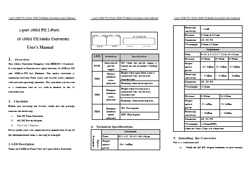
1-port 100M FX 2-Ports10/100M TX Media ConvertersUser’s Manual 1.OverviewThis Media Converter Complies with IEEE802.3 Standards. It is designed to Convert data signal between 10/100Base-TX and 100Base-FX fast Ethernet. The media converter is connected between Fiber cable and twisted cable segments with network operating smoothly. This converter can be used as a standalone unit or asa slide-in module to the 14 converter rack.2.ChecklistBefore you installing the Switch, verify that the package contains the following:1.The TP-Fiber Converter2.AC-DC Power Adapter.3.This User’s Manual.Piease notify your sales representative immediately if any of the aforementioned items is missing or damaged.3. LED DescriptionThere are 6 LED At Front View of 2 port Media ConverterLED Definition SpecificationPWRIndicator ofpowersupplyON when the power supply isturned on and in normal workingstatusFRXOpticalinterfacestatusindicatorBright when optic fiber cable isconnected well, but no datatransmissionBlinking when receiving dataTRXEthernetinterfacestatusindicatorBright when twisted pair isconnected well, but no datatransmissionBlinking, when receiving dataFDXEthernetinterfacemodeindicatorON, Full duplexOFF, Half duplex4.Technical SpecificationsOptical ParametersMultimodeFiber 62.5/125, 50/125,100/140µmOutputopticalpower-20~-14dBmReceivingsensitivity<-31dBDistance 0~2km or 0~5kmConnector SC, ST, FCWavelength 850nm/1310nmSinglemodeFiber 9/125,8.3/125,8.7/125or 10/125µmDistance 0~20km 0~40km 0~60kmOutputopticalpower-12~-8dBm -8~-3dBm -3~ 0dBmReceivingsensitivity< -37dBm < -37dBm < -38dBmConnector SC, ST, FCWavelength 1310nmDistance 0~80km 0~120kmOutputopticalpower-3~ 1dBm -3~ 2dBmReceivingsensitivity< -38dBm < -38dBmConnector SC, ST, FCWavelength 1550nm(DFB)when less than 15km, use attenuator5.Installing the ConverterFor as a standalone unita)Verify the AC-DC adapter conforms to your countryAC Power requirement and insert the power plugb)Connect the media cable for network connectionfor as a slide-in unitc)The slide-in Media Converter and Converter Rackshould be supplied only form the same source, bothMedia Converter and Rack are built to match eachother at dimensions, DC jack, DC receptacle andpower safelyd)Turn off the 19” converter rack powere)Ensure that there is no activity in the networkf)Locate +5VDC power jack on converter back,carefully slide in and plug to 19” rack +5VDCpower receptacleg)Connect the media cable for network connectionh)Turn on the converter rack power , the Power LEDwill light up6.Cable Connection Parameter100Base-X network allows 512-bit time delay between any two node stations in a collision domain. The overall Bit-timeof TP/Fiber wires and devices must be within 512bit in a segment. You may use a switch to break up collision domain and extend the cabling distance.●TP Cable Limitations:Cat.5 100m●Multi-mode Converter Fiber Cable Lions:SC/ST/FC/LC Multi-mode Converter Models:Multi-modeFull-duplexNode to Node :2KmNode to Switch :2KmSC/ST/FC/LC Single Mode Converter Models:SC.S20Full-duplexNode to Node :20KmNode to Switch :20Km7.TP-Fiber Technical Specifications●Standards:I EEE802.3 IEEE802.3u 10/100Base-TX 100Base-Fx●TP Port: RJ45●UTP Cable: Cat.5 cable up to 100m●Wavelength: 1310nm/1550nm●Fiber cable(um):50/125,62.5/125,or 100/140/um multi-mode8.3/125,8.7/125,9/125/or10/125/um single-mode●Max distance:Singlemode:20~120kmMultimode: 2km●LED Indicators:FDX, TRX FRX,PWR●Data Transfer Rate:Speed Forwarding Rate100Mbps 148,800PPS10Mbps 14,880PPS*Flow Control:IEEE802.3x compliant for full-duplex Backpressure flow control for half-duplex* Power Requirement:2A@+5VDC*Ambient Temperatur e:0 to 60℃* Humidity:5% to 90%*Dimensions: 25(H)70 (W)94(D)mm●Note: Connecting to Router, Bridge, or Switch, pleaserefer to the device's Technical Manual。
Skylane Optics 光纤收发器产品手册说明书

PUBLIC_REV2017_AProduct GuideTransceivers for Datacom and TelecomApplicationsData CenterOptimized fiber optic solution for Data Center Application FTTHBroad Product Portfoloio and Technology for FTTH Broadband Networks WirelessEnabling Rapid Expnsion of Mobile Broadband Enterprise - CampusWe provides the enterprise network market with the most comprehensive product combinationsSkylane Optics is a leading provider of transceivers for optical communication. We offer an extensive portfolio for the enterprise, access, and metropolitan fiber optical market.The offerings provided by Skylane Optics are characterized by high quality and performance. In combination with our strong technical support, we enable our customers to build cost optimized network solutions solving existing and future capacity needs.SolutionsOur Engineering and Logistics Center> Inventory, logistics, programming and quality control based in Fraire, Belgium> IQC [Incoming Quality Control] and OQC [Outgoing Quality Control]> 100% optimized for handling of transceivers > SD [ANSI/ESD S20.20] compliant > Clean room environment; class 100K > Traceability> High CapacityOur Laboratory> Lab, based in Fraire, Belgium > Technical support > RMA handling> Qualification tests:- Measure performance over the temperaturerange to verify compliance with standards - Compliance with standards (IEEE, IEC, MSA)- Power consumption - Eye diagram - Sensitivity- WavelengthQualityCompatibilityAdva Agilent Alcatel - Nokia Allied Telesis Apac Opto AristaArborAruba Networks AsgaAvaya – Nortel BlackMagic Broadcom BrocadeBTI System BullCalix Carelink CienaCiscoCitrixCOE Commscope Coriant Corrigent CPECyanD-Link datacomDellDNWPECIEdge-Core Enterasys EricssonEricsson RedbackExtremeFibrolanForce10Fortigate (Fortinet)GeneexisGigamonHirschmanHPHP - ProcurveHP - H3CHP - BladeSystemHP - SANHP - ServerHSEHuaweiIBMID QuanticInfineraIntelIXIAJDSUWavereadyJuniperKeymileKTILANCOMLinksysLynxMellanoxMerakiMicrosensMikrotikMoxaMRVLynxMarconiMikrotikMyricomNECNetgearNexansOptowayOrckitPacketfrontPacketlightPalo AltoPica8Procera NetworksQlogicRADRadwareRiverstoneSorentoTellabsTP-LinktrendnetTransition NetworksUnifi - SwitchVSSWestermoWTDZhoneZTEZyxelHIGHLY COMPATIBLE : MAKE YOUR TRANSCEIVER COMPATIBLE FOR ALL MAJOR PLATFORM.WhySkylane Optics ?CustomizationDue to our high experienced engineers, we are enable to modify the hardware and software of the transceivers. We are also able to produce transceivers with withelabelling.Technical SupportHighly experienced Skylane Optics engi -neers will visit your facility to solve your issues.Quality & AssuranceWe have cutting-edge test equipment to ensure we supply high quality products.Mutli CompatibilitySkylane Optics offers the most cost-effec -tive solutions for all major platforms withthe proprietary firmware.Innovations for Early AdoptersThe manufacturing environment is strictly compliant to most avanced standard, whichensure long term reliability.Skylane Optics transceivers are certified by TUV.> E N 60950-1:2006 ITE, Safety, General require -ments > EN 60825-1:2007 Safety of laser products > EN 60825-2:2004 Safety of Optical Fiber Com -munication SystemsSkylane Optics transceivers are CE and ROHS compliant.Skylane Optics transceivers are certified by ULCertificationsT R A N S C E I V E R ST R A N S C E I V E R S P O NC A B L E SC OD I N G B O XP A S S I V E S(V i s i b i l e o n o u r w e b s i t e )Q S F P28100GBase-SR4Q2885P10C0PF103 Gb/s Multi Mode850nm 100m0°C to 70°C 100GBase-SR4/OTU4Q2885P10C1PF112 Gb/s Multi Mode850nm100m0°C to 70°C 100GBase-eSR4Q2885P30C0PF103 Gb/s Multi Mode850nm300m0°C to 70°C 100GBase-eSR4/OTU4Q2885P30C1PF112 Gb/s Multi Mode850nm300m0°C to 70°C 100GBase-PSM4Q2813P50C0PD103 Gb/s Single Mode1310nm500m0°C to 70°C100GBase-CWDM4Q28QL002C00F103 Gb/s Single Mode1270/1290/1310/1330nm2km 0°C to 70°C 100GBase-CLR4Q28QL002C00D103 Gb/s Single Mode1270/1290/1310/1330nm 2km 0°C to 70°C 100GBase-LR4Q28QD010C00D103 Gb/s Single Mode LAN-WDM 800GHz10km 0°C to 70°C 100GBase-LR4/OTU4Q28QD010C10D112 Gbps Single Mode LAN-WDM 800GHz10km 0°C to 70°C 100GBase-ER4 Lite Q28QD040C00F103 Gb/s Single Mode LAN-WDM 800GHz40km 0°C to 70°C 100GBase-ER4/OTU4 Lite Q28QD040C10F112 Gbps Single Mode LAN-WDM 800GHz40km 0°C to 70°CC F P4100GBase-LR4CF4QD010C00D103 Gb/s Single Mode LAN-WDM 800GH z10km0°C to 70°C 100GBase-LR4/OTU4CF4QD010C10D112 Gbps Single Mode LAN-WDM 800GH z10km 0°C to 70°C 100GBase-ER4 Lite CF4QD040C00F103 Gb/s Single Mode LAN-WDM 800GH z40km0°C to 70°C 100GBase-ER4/OTU4 Lite CF4QD040C10F112 Gbps Single Mode LAN-WDM 800GH z40km 0°C to 70°CC F P2100GBase-LR4CF2QD010C00D103 Gb/s Single Mode LAN-WDM 800GH z10km0°C to 70°C 100GBase-LR4/OTU4CF2QD010C10D112 Gbps Single Mode LAN-WDM 800GH z10km 0°C to 70°C 100GBase-ER4CF2QD040C00D103 Gb/s Single Mode LAN-WDM 800GH z40km0°C to 70°C 100GBase-ER4/OTU4CF2QD040C10D112 Gbps Single Mode LAN-WDM 800GH z40km 0°C to 70°CC F P100GBase-LR4CFPQD010C00D103 Gb/s Single Mode LAN-WDM 800GH z10km0°C to 70°C 100GBase-LR4 OTU4CFPQD010C10D112 Gbps Single Mode LAN-WDM 800GH z10km 0°C to 70°C 100GBase-ER4CFPQD040C00D 103 Gb/s Single Mode LAN-WDM 800GH z40km0°C to 70°C 100GBase-ER4/OTU4CFPQD040C10D112 Gbps Single Mode LAN-WDM 800GH z40km 0°C to 70°CQ S F P+40GBase-SR4QFP85xxx40PD 40 Gb/s Multi Mode850nm 100/300m0°C to 70°C 40GBase-PSM4 IR4 QFP13C1440PD40 Gb/s Single Mode1310nm1,4km0°C to 70°C 40GBase-PSM4 LR4QFP1301040PD40 Gb/s Single Mode1310nm10km 0°C to 70°C40GBase-IR4QFPQLC1400D40 Gb/s Single Mode1270/1290/1310/1330nm1,4km 0°C to 70°C 40GBase-LX4QFPQL002400U40 Gb/s Single/Multi Mode1270/1290/1310/1330nm2km 0°C to 70°C 40GBase-LR4QFPQL010400D40 Gb/s Single Mode1270/1290/1310/1330nm 10km 0°C to 70°C 40GBase-ER4QFPQL040400D40 Gb/s Single Mode1270/1290/1310/1330nm40km 0°C to 70°CS F P2825GBase-SR S2885P10250F25 Gb/s Multi Mode850nm100m-40°C to 85°C 25GBase-LR S2813010250D25 Gb/s Single Mode1310nm10km-40°C to 85°C 25GBase-ER S2813040250F25 Gb/s Multi Mode1310nm40km0°C to 70°C25GBase-CWDM S2CXX010250D25 Gb/s Single Mode CWDM ITU ch. 10km-20°C to 85°CX F P10GBase-SR XFP85P3010xD10.3 Gb/s Multi Mode850nm 300m -40°C to 85°C 10GBase-LR XFP1301010xD10.3 Gb/s Single Mode1310nm 10km -40°C to 85°C 10GBase-LR/OC-192XFP130100HxD11.35 Gb/s Single Mode1310nm 10km -40°C to 85°C 10GBase-LR XFP1302010xD10.3 Gb/s Single Mode1310nm 20km -40°C to 85°C 10GBase-ER XFP1504010xD10.3 Gb/s Single Mode1550nm 40km -40°C to 85°C 10GBase-ER/OC-192XFP150400HxD11.35 Gb/s Single Mode1550nm 40km -40°C to 85°C 10GBase-ZR XFP1508010xD10.3 Gb/s Single Mode1550nm 80km -40°C to 85°C 10GBase-ZR/OC-192XFP150800HxD11.35 Gb/s Single Mode1550nm 80km -40°C to 85°C10GBase-CWDM XFCxxB1010xD10.3 Gb/s Single Mode CWDM ITU ch. 10dB -40°C to 85°C 10GBase-CWDM XFCxx04010xD10.3 Gb/s Single Mode CWDM ITU ch. 14dB/40km -40°C to 85°C 10GBase-CWDM XFCxx07010xD10.3 Gb/s Single Mode CWDM ITU ch. 23dB/70km -40°C to 85°C10GBase-DWDM XFDxx04010xD10.3 Gb/s Single Mode DWDM ITU ch. 14dB/40km -40°C to 85°C 10GBase-DWDM/OC-192XFDxx0400HxD11.35 Gb/s Single Mode DWDM ITU ch. 14dB/40km -40°C to 85°C 10GBase-DWDM XFDxx08010xD10.3 Gb/s Single Mode DWDM ITU ch. 23dB/80km -40°C to 85°C 10GBase-DWDM OC-192XFDxx0800HxD11.35 Gb/s Single Mode DWDM ITU ch. 23dB/80km -40°C to 85°C10GBase-Tunable XFDTU0800H0D11.35 Gb/s Single Mode50GHz DWDM tun 23dB/80km0°C to 70°C10GBase-Bidi XFB23xxx10xD10.3 Gb/s Single Mode1270/1330nm 10/20/40/60km-40°C to 85°C 10GBase-Bidi XFB32xxx10xD10.3 Gb/s Single Mode1330/1270nm10/20/40/60km-40°C to 85°CX2X2X2S00000100D 10.3 Gb/s n/a n/a n/a0°C to 70°C X E N P A KXenpak XPS00000100D 10.3 Gb/s n/a n/a n/a0°C to 70°CS F P+16x Fiber Channel SW SPP85P10160C14.025 Gb/s Multi Mode850nm100m0°C to 70°C 16x Fiber Channel LW SPP13010160C14.025 Gb/s Single Mode1310nm10km0°C to 70°C 6G CPRI SR SPP85P30L6xD 6.144 Gb/s Multi Mode850nm300m-20°C to 85°C 6G CPRI LR SPP13002L6xD 6.144 Gb/s Single Mode1310nm2km-40°C to 85°C 6G CPRI LR SPP13010L62D 6.144 Gb/s Single Mode1310nm10km-40°C to 85°C 10GBase-SR SPP85P3010xD10.3 Gb/s Multi Mode850nm300m-40°C to 85°C 10GBase-LRM SPP13P2210xA10.3 Gb/s Multi Mode1310nm220m-40°C to 85°C 10GBase-LR SPP13xxx10xD10.3 Gb/s Single Mode1310nm10/20km-40°C to 85°C 10GBase-ER SPP1504010xD10.3 Gb/s Single Mode1550nm40km-40°C to 85°C 10GBase-ZR SPP1508010xD10.3 Gb/s Single Mode1550nm80km-40°C to 85°C 10GBase-ZR100SPP15100100D10.3 Gb/s Single Mode1550nm100km0°C to 70°C10GBase-CWDM SPCxxB1010xD10.3 Gb/s Single Mode CWDM ITU ch. 10dB-40°C to 85°C 10GBase-CWDM SPCxx04010xD10.3 Gb/s Single Mode CWDM ITU ch.14dB/40km-40°C to 85°C 10GBase-CWDM SPCxx07010xD10.3 Gb/s Single Mode CWDM ITU ch.23dB/70km-40°C to 85°C6G CPRI CWDM SBHxDxxxL62D 6.144 Gb/s Single Mode CWDM ITU ch.10dB/18dB-40°C to 85°C 6G CPRI CWDM SBHxUxxxL62D 6.144 Gb/s Single Mode CWDM ITU ch.10dB/18dB-40°C to 85°C10GBase-DWDM SPDxx04010xD10.3 Gb/s Single Mode DWDM ITU ch. 14dB/40km -40°C to 85°C 10GBase-DWDM SPDxx08010xD10.3 Gb/s Single Mode DWDM ITU ch.23dB/80km-40°C to 85°C10GBase-Tunable SPDTU08010xD11.35 Gb/s Single Mode50GHz DWDM tun23dB/80km-40°C to 85°C10GBase-Bidi SPB23xxx10xD10.3 Gb/s Single Mode1270/1330nm 10/20/40/60km-40°C to 85°C 10GBase-Bidi SPB32xxx10xD10.3 Gb/s Single Mode1330/1270nm10/20/40/60km-40°C to 85°C 10GBase-Bidi SPB45080100D10.3 Gb/s Single Mode1490/1550nm80km0°C to 70°C 10GBase-Bidi SPB54080100D10.3 Gb/s Single Mode1550/1490nm80km0°C to 70°C10GBase-T SPT00M30100010.3 Gb/s Copper n/a30m0°C to 70°CS F P100Base-LX SF P13xxxFExD125 Mb/s Single Mode1310nm2/10/20/30/40/60km-40°C to 85°C 100Base-LX SGMII SGP13xxxFExD125 Mb/s Single/Multi Mode1310nm2/10km -40°C to 85°C 100Base-ZX SFP15080FExD125 Mb/s Single Mode1550nm 80km -40°C to 85°C 1000Base-SX SFP85P55GExD 1.25 Gb/s Dual Fibre-MM850nm 550m -40°C to 85°C 1000Base-LX SFP13001GExD 1.25 Gb/s Dual Fibre-MM1310nm 2km -40°C to 85°C 1000Base-LX40SFP13xxxGExD 1.25 Gb/s Single Mode1310nm 10/20km -40°C to 85°C 1000Base-EX SFP13040GExD 1.25 Gb/s Single Mode1310nm 40km -40°C to 85°C 1000Base-ZX SFP15xxxGExD 1.25 Gb/s Single Mode1550nm 60/80/120km -40°C to 85°C 0C-48 Multi Rate SX SFP13002PAxD 2.67 Gb/s Single Mode1310nm 2km -40°C to 85°C 0C-48 Multi Rate LX SFP13020PAxD 2.67 Gb/s Single Mode1310nm 20km -40°C to 85°C OC-48 Multi Rate LX40SFP13040PAxD 2.67 Gb/s Single Mode1310nm 40km -40°C to 85°C 0C-48 Multi Rate EX SFP15040PAxD 2.67 Gb/s Single Mode1550nm 40km -40°C to 85°C 0C-48 Multi Rate ZX SFP15080PAxD 2.67 Gb/s Single Mode1550nm 80km -40°C to 85°C 3G CPRI Base-SX SFP85P30L31D 3.072 Gb/s Multi Mode850nm300m-20°C to 85°C 3G CPRI SX SFP13002L32D 3.072 Gb/s Single Mode1310nm2km-40°C to 85°C 3G CPRI LX SFP13010L32D 3.072 Gb/s Single Mode1310nm10km-40°C to 85°C1000Base-CWDM SFCxx040GE0D 1.25 Gb/s Single Mode CWDM ITU ch. 16dB/40km 0°C to 70°C 1000Base-CWDM SFCxx080GE0D 1.25 Gb/s Single Mode CWDM ITU ch. 24dB/80km 0°C to 70°C 1000Base-CWDM SFCxx120GE0D 1.25 Gb/s Single Mode CWDM ITU ch. 32dB/120km 0°C to 70°C 1000Base-CWDM SFCxx160GE0D 1.25 Gb/s Single Mode CWDM ITU ch. 40dB/160km 0°C to 70°C 4x Fiber Channel-CWDM SFCxx0404F0D 4.25Gb/s Single Mode CWDM ITU ch. 16dB/40km0°C to 70°C 4x Fiber Channel-CWDM SFCxx0804F0D 4.25Gb/s Single Mode CWDM ITU ch. 24dB/80km0°C to 70°C OC-48 Multi Rate CWDM SFCxx040PAxD 2.67Gb/s Single Mode CWDM ITU ch. 16dB/40km-20°c to 85°C OC-48 Multi Rate CWDM SFCxx080PAxD 2.67Gb/s Single Mode CWDM ITU ch. 24dB/80km-20°c to 85°C3G CPRI Bidi CWDM SBHxDB22L32D 3.072 Gb/s Single Mode CWDM ITU ch. 22dB-40°C to 85°C 3G CPRI Bidi CWDM SBHxUB22L32D 3.072 Gb/s Single Mode CWDM ITU ch. 22dB-40°C to 85°C1000Base-DWDM SFDxxyyyGE0D 1.25 Gb/s Single Mode DWDM ITU ch. 80/100/120km0°C to 70°C1000BASE-T SFT00P10GE0x 1.25 Gb/s Copper n/a100m 0°C to 70°C 1000BASE-T SGT00P10DR0x 1.25 Gb/s Copper n/a100m 0°C to 70°C1000Base-BXD SBD53xxxFExD125 Mb/s Single Mode1550/1310nm 10/20/40/60km -40°C to 85°C 1000Base-BXU SBU35xxxFExD125 Mb/s Single Mode1310/1550nm 10/20/40/60km -40°C to 85°C 1000Base-BXD SGMII SGD53010FExD125 Mb/s Single Mode1550/1310nm 10km -40°C to 85°C 1000Base-BXU SGMII SGU35010FExD125 Mb/s Single Mode1310/1550nm 10km -40°C to 85°C 1000Base-BXD SBD53xxxGExD 1.25 Gb/s Single Mode1550/1310nm 3/10/20/40/60km -40°C to 85°C 1000Base-BXU SBU35xxxGExD 1.25 Gb/s Single Mode1310/1550nm 3/10/20/40/60km -40°C to 85°C 1000Base-BXD SBD43xxxGExD 1.25 Gb/s Single Mode1490/1310nm 10/20/40/60km -40°C to 85°C 1000Base-BXU SBU34xxxGExD 1.25 Gb/s Single Mode1310/1490nm 10/20/40/60km -40°C to 85°C 1000Base-BXD SBD43xxxDRxD 1.25 Gb/s Single Mode1490/1310nm 10/20km -40°C to 85°C 1000Base-BXU SBU34xxxDRxD 1.25 Gb/s Single Mode1310/1490nm 10/20km -40°C to 85°C 1000Base-BXD SBD53xxxDRxD 1.25 Gb/s Single Mode1550/1310nm 10/20km -40°C to 85°C 1000Base-BXU SBU35xxxDRxD 1.25 Gb/s Single Mode1310/1550nm 10/20km -40°C to 85°C1000Base-BXD CSFP SCD53xxxDRxD 1.25 Gb/s Single Mode1550/1310nm 10/20km 0°C to 70°C 1000Base-BXD CSFP SCD53xxxGExD 1.25 Gb/s Single Mode1550/1310nm 10/20km 0°C to 70°C 1000Base-BXD CSFP SCD43xxxGExD 1.25 Gb/s Single Mode1490/1310nm 10/20/40km0°C to 70°CTransceivers PONGPON OLT B+SBM43CBPDGxD 2,488 Mbps 1,244 Mbps Bidi SFP 1490/1310nm DFB APD B+ -40°C to 85°C SC GPON OLT C+SBM43CCPDGxD 2,488 Mbps 1,244 Mbps Bidi SFP 1490/1310nm DFB APD C+ -40°C to 85°C SC GPON OLT C++SBM43CCCDG3D2,488 Mbps1,244 MbpsBidi SFP1490/1310nmDFBAPDC++0°C to 70°CSCXGSPON OLTXSM52CN1NN3D9,953 Mbps9,953 MbpsBidi XFP1577/1270nmEMLAPDN10°C to 70°CSCXGSPON OLT SSM52CN1NN3D 9,953 Mbps 9,953 Mbps Bidi SFP+1577/1270nm EML APD N10°C to 70°C SC XGSPON ONUSSN25CN1XXxD10,3125 Mbps10,3125 MbpsBidi SFP+1270/1577nmEMLAPDN1-40°C to 85°CSC10GEPON OLTSPH53C30XR3D 10,3125 Mbps 1,25 Mbps Bidi SFP+1577/1310nm EML APD PRX300°C to 70°C SC 10GEPON ONUSPI25C30PR3D 10,3125 Mbps 10,3125 Mbps Bidi SFP+1270/1577nm EML APD PR300°C to 70°C SC SPI35C30RX3D 1,25 Mbps 10,3125 Mbps Bidi SFP+1310/1577nm DFB APD PRX300°C to 70°C SC XGPON1 OLT SPF52CN1ND3D 9,953 Mbps 2,488 Mbps Bidi SFP+1577/1270nm EML APD N10°C to 70°C SC XGPON1 ONUSPG25CN1DNxD2,488 Mbps9,953 MbpsBidi SFP+1270/1577nmDFBAPDN1-40°C to 85°CSC10GEPON OLT XBO52C30PR3D 10,3125 Mbps 10,3125 Mbps Bidi XFP 1577/1270nm EML APD PR300°C to 70°C SC XGPON1 OLTXBM52CN1ND3D9,953 Mbps2,488 MbpsBidi XFP1577/1270nmEMLAPDN10°C to 70°CSCX F PS F PS F P +A L L P R O D U C T S A R E D D MQ S F P 28Q S F P +100GBase-T DAPQQMxxC000QSFP28 to QSFP28103 Gb/s n/a n/a n/a 50cm/1/2/3m 100xGigabit Ethernet 0°C to 70°C 1100GBase-T Breakout CableDAPQSMxxC000QSFP28 to 4x SFP28103 Gb/sn/an/an/a50cm/1/2/3m25x/100x Gigabit Ethernet0°C to 70°C1,2100GBase DAOQQMxxC00D QSFP28 to QSFP28103 Gb/s 850nm 4x VCSEL 4xPIN 1/3/5/10/15/30/50/75/100m 100xGigabit Ethernet 0°C to 70°C 1100GBaseBreakout CableDAOQSMxxC00DQSFP28 to 4x SFP28103 Gb/s850nm4x VCSEL4xPIN50cm/1/2/3m25x/100x Gigabit Ethernet0°C to 70°C1,240GBase-T (passive)DAPQQxxx4000QSFP+ to QSFP+40 Gb/s n/a n/a n/a 50cm/1/2/3/4/5m 40xGigabit Ethernet 0°C to 70°C 140GBase-T Breakout DAPQSxxx4000QSFP+ to 4x SFP+40 Gb/s n/a n/a n/a 50cm/1/2/3/4/5m10x/40x Gigabit Ethernet 0°C to 70°C 1,240GBase-T (active)DAAQQMxx4000QSFP+ to QSFP+40 Gb/sn/an/an/a7/10m40xGigabit Ethernet0°C to 70°C140GBase DAOQQxxx400D QSFP+ to QSFP+40 Gb/s 850nm 4x VCSEL 4xPIN 3/5/10/30/50/100m 40xGigabit Ethernet 0°C to 70°C 140GBaseBreakout CableDAOQSMxx400DQSFP+ to 4x SFP+40 Gb/s850nm4x VCSEL4xPIN3/5/10/30/50/100m10x/40x Gigabit Ethernet0°C to 70°C1,21 M x x & x x x I N P A R T N U M B E R I N D I C A T E S C A B L E L E N G T H.2 B R E A K O U T C A B L E.25GBaseDAOSSMxx250DSFP28 to SFP2825 Gb/s850nmVCSELPIN1/2/3/5/10/20/30/50/100m25xGigabit Ethernet0°C to 70°C1S F P 28S F P +25GBase-TDAPSSMxx2500SFP28 to SFP2825 Gb/sn/an/an/a50cm/1/2/3/5m25xGigabit Ethernet0°C to 70°C110GBaseDAOSSxxx100DSFP+ to SFP+10.3 Gb/s850nmVCSELPIN1/3/5/7/10/15/20/30/50/100m10x Gigabit Ethernet 10x Fibre Channel0°C to 70°C110GBase-T (passive)DAPSSMxx1000SFP+ to SFP+10.3 Gb/s n/a n/a n/a 50cm/1/2/3/5/7m 10x Gigabit Ethernet 10x Fibre Channel 0°C to 70°C 110GBase-T (active)DAASSxxx1000SFP+ to SFP+10.3 Gb/sn/an/an/a1/2/3/5/7/10m10x Gigabit Ethernet 10x Fibre Channel0°C to 70°C11 M x x & x x x I N P A R T N U M B E R I N D I C A T E S C A B L E L E N G T H.2 B R E A K O U T C A B L E.Coding BoxThe SkyBox is a solution, provided and managed by Skylane Optics , enabling our customer to program Skylane Optics transceivers by themselves.Customers can now easily make SFP/ SFP+/ SFP28 / CSFP , XFP , QSFP+/ QSFP28 and XFP transceivers compatible with equipment from a large number of vendors (Cisco, Juniper, HP , …).The wavelength of Skylane tunable transceivers can also be set to the desired value using SkyBox . To allow use of SkyBox in any situation, the box comes with a battery.By the way, you never know where you must reprogram and install your transceivers!As the world is getting more and more connected the SkyBox comes with a mobile and desktop applica -tion compatible with android ® and Mac OS ®.With this toolbox, you are able to code your transceivers but also to see the history of all your previous coding activities.Furthermore, other options can be added such as OTDR, Power Meter, VOA, Wavelength meter.There is no other brand offering a battery-powered coding box.The SkyBox is a real partner for you engineers on the field. With SkyBox, you do not need to code your transceiver before leaving the office. You can do everything on the field.M ain benefitsUser Friendly The SkyBox is provided with a mobile and desktop application.Cost-effective Solution Less part numbers needed and stock management/logistics will be simplified.H ighly CompatibleMake your transceiver compatible for all major platform.ContactP20PRODUCT GUIDE B E L G I U MR u e d u M o u l i n , 18B -5650 F r a i r e B e l g i u mT. +32 71 610 640F. +32 71 610 649E. i n f o @s k y l a n e o p t i c s.c o m R u a U m b u 286 - 1º p a v i m e n t o A l p h a v i l l e C a m p i n a s E m p r e s a r i a l C E P 13.098-325 C a m p i n a s S ão P a u l o - B r a s i l T.+55 (19) 3514-6000E. i n f o @s k y l a n e o p t i c s.c o m V i k d a l s g r än d , 10A 13140 N a c k a S w e d e n E. i n f o @s k y l a n e o p t i c s.c o m B R A Z I L S W E D E N U S A (C O M I N G S O O N )F O L L O W U S O N :Tw i t t e r | L i n k e d I nO U R O F F I C E S A R O U N D T H E W O R L D。
OPT-100光纤收发器用户手册

快速以太网光纤收发器FAST Ethernet Media Converter用户手册USER MANUALEdision: 1.0OPT-100光纤收发器用户手册一.概述OPT-100系列光纤收发器通过把原来在双绞线上传输的以太网电信号转换为在光纤上传输的光信号,极大地延伸了以太网的连接距离。
OPT-100系列光纤收发器的光接口满足IEEE802.3u 100Base-FX标准;电接口满足IEEE802.3 10Base-T和IEEE802.3u 100Base-TX标准,支持10/100M、全双工/半双工自动协商,可以灵活地满足局域网的用户和网络系统集成商的组网需求。
OPT-100光纤收发器依据光传输介质的不同分为多模、单模双纤和单模单纤三种。
由于单纤双向收发器的光信号采用波分复用技术,发送波长和接收波长不同,即一台设备发送波长为1310nm、接收波长为1550nm,另一台设备发送波长为1550nm、接收波长为1310nm,因此必须配对使用。
二.技术指标△符合 IEEE 802.3、IEEE 802.3u、IEEE 802.3X、10Base-TX、100Base-TX、100Base-FX 标准。
△符合电信级运营标准,平均无故障时间大于5万小时。
△支持TCP/IP、PPPOE、DHCP、ICMP、NAT等协议。
△流控方式:全双工采用IEEE 802.3X,半双工采用Backpressure标准。
△内置高效交换核心,高速缓存容量为1Mbit,MAC地址列表深度为1K。
△电口支持自动协商功能,自动调整传输方式和速率。
△电口支持Auto-MDI/MDIX自动翻转。
△支持存储转发模式。
△支持最长1552 Byte超长数据包传输。
△支持QoS,保证VOIP数据包传输。
△支持STP生成树,构成冗余网络。
△接口: 电口: RJ45 光口: SC△双绞线: 超5类、6类△单模光纤: 8/125、8.3/125、9/125µm△工作温度: 0 ~ 50℃△存储温度: -20 ~ 70℃△湿度: 5% ~ 90%△外形尺寸:长 * 宽 * 高 = 92 *68 *28 (mm)三.产品安装请按以下步骤安装光纤收发器:a)将光纤终端盒引出的光纤跳线或尾纤插到设备的光口。
光纤收发器说明书

产品名称: N-net 10/100M自适应以太网光纤收发器N-net 10/100M自适应以太网光纤收发器产品说明:N-net 10/100M自适应以太网光纤收发器概述NT-1100/NT-1100S 10/100M自适应以太网光纤收发器,可以将10/100Base-TX的双绞线电信号和100Base-FX的光信号进行相互转换。
它将网络的传输距离极限从铜线的100米扩展到100公里(单模光纤)。
典型应用是以太网距离互连,例如小区机房与城域网的连接。
由于具有自适应的功能,在与交换机连接时,交换机不需要任何设置。
新增防雷功能,保证了设备的安全性。
外置电源、内置电源可选交流220V、直流-48V 可选N-net 10/100M自适应以太网光纤收发器产品特性:自适应NT-1100/NT-1100S具有10/100M速率自适应,全/半双工自适应功能。
在网络升级时极大保护了原有的网络投资。
大容量缓存独有的缓存技术可以保证您的网络在数据传输及多媒体应用时表现得更为出色,缓存为2M。
N-net 10/100M自适应以太网光纤收发器性能:N-net 10/100M自适应以太网光纤收发器骨干特性符合:10Base-T标准符合:100Base-TX/FX标准符合:标准N-net 10/100M自适应以太网光纤收发器端口传输速率光口:100Mbps电口:10/100Mbps交叉线与直通线自动识别NT-1100/NT-1100S与交换机或服务器等设备相连时,既可以使用交叉线也可以用直通线。
TX LINK/ACT灯亮,表示链路连通正确。
N-net 10/100M自适应以太网光纤收发器双工支持NT-1100/NT-1100S支持全/半双工自适应,10/100M自适应。
N-net 10/100M自适应以太网光纤收发器网络线缆10/100Base-TX UTP 5类线100Base-FX:多模光纤50/125,125或100/140μm单模光纤125,125,9/125或10/125μmN-net 10/100M自适应以太网光纤收发器传输距离10/100Base-TX:100米100Base-FX:2公里(多模),25/40/60/100公里(单模)N-net 10/100M自适应以太网光纤收发器光接口特性:波长:1310nm(25公里、40公里、2公里)1550nm(100公里)1310nm(多模2公里)N-net 10/100M自适应以太网光纤收发器LED显示:PWR:电源指示灯FX LINK/ACT:光链路连接/活动状态指示灯TX LINK/ACT:电链路连接/活动状态指示灯FX100:光口速率指示灯TX100:电口速度指示灯FDX:全、半双工指示灯N-net 10/100M自适应以太网光纤收发器端口配置:1个RJ45 10/100Base-TX端口1个SC/ST 多模/单模双工连接头N-net 10/100M自适应以太网光纤收发器电源要求:外置电源:5VDC 1A功耗:<5W内置电源:220VAC、-48VDC功耗:<5WN-net 10/100M自适应以太网光纤收发器环境要求:工作温度范围:0℃~60℃储存温度范围:-40℃~85℃相对湿度:5%~90%尺寸:电源外置式:26mm×71mm×94mm电源内置式:40mm×110mm×140mm以太网光纤收发器以太网光纤收发器机架说明书(使用前先阅本说明书)目录第一章10/100M光纤收发器说明书.................. 错误!未定义书签。
Allied Telesis 光纤转换器产品说明书

Connectivity GuideProduct Catalog | 1Allied Telesis2 |ETHERNET AND FAST ETHERNET STANDALONE MEDIA CONVERTERSMC13MC101XLMC102XLMC103XLMC103LHMC104XLMC115XLMC116XL10T 100TX 100TX 100TX 100FX MMF (SC)10T or 100TX 10T or 100TX Allied Telesis media converters enable the connection of disparate cabling types in networks where many cabling types exist. Network segments may also operate at different speeds, and media converters can be used to convert between speeds. Typically, media converters are used to connect copper and fiber-optic cabling that coexist in a network. Converters exist in a variety of standalone, multi-port, and modular forms. These different physical forms address the need for different applications and conversion densities.MMCThe Allied Telesis MMC Series of FastEthernet mini media converters leverages its smaller size to not only help the environment with a small carbon footprint, but also to save space in its working environment. Despite its compact size, the MMC Series delivers all the power and functionality of standard size media converters.PoEAllied Telesis PC PoE Series switches are the ideal solution for powering remote devices such as IP phones, video cameras, wireless access points, etc., which are more than 100 m from a Power over Ethernet switch.Desktop PoweredThe Allied Telesis DMC1000 Series of Gigabit mini media converters are among the smallest media converters in the market today. At just 1.25 in wide x 3.6 in deep x 0.85 in high, these media converters can easily fit into the palm of your hand. In addition to being compact — with a small carbon footprint — the DMC1000 Series can also be powered with the included micro USB to USB cable, and plugged directly into a laptop or PC. This saves installation time and cabling as there are no further power requirements necessary.Allied Telesis media converters extend network distances by adding fiber and VDSL (via coax and telephone-grade twisted pair) onlywhere it is needed. This enables customers to keep pace with changing technology and to integrate high-bandwidth devices into the network without changing the entire network infrastructure. From standalone units to chassis-based blades, Allied Telesis media converters are highly configurable to meet every need.Media ConvertersStandaloneFAST ETHERNET AND GIGABIT ETHERNET STANDALONE MINI MEDIA CONVERTERS10/100TX10/100TX10/100/1000T100FX (LC)100FX (SC)1000SX (LC)MMF MMF MMF100FX100FX1000SX1310 nm850 nmMMC200/LC MMC200/SC MMC2000/LCGIGABIT ETHERNET STANDALONE MEDIA CONVERTERSMC1004MC1008/SP1000T1000T1000SX (SC)SFP* Dependant on SFPMedia Converters | 3Allied Telesis4|Desktop PoweredUniversal Power SupplyFor customers already using Allied Telesis media converters, replacement power adapters are available.▶MCPWRUniversal, high-efficiency external power adapterFAST ETHERNET AND GIGABIT DESKTOP USB POWEREDMissingLinkThe Allied Telesis MissingLink ™feature enables media converters to pass the link status of their connections and therebytrigger corrective action when a problem on a link is detected.For example, if the twisted-pair cable to the 10/100TX port on an Allied Telesismedia converter were to fail, the unit would respond by dropping the link on the 100FX fiber-optic port.Most managed devices, such as switches and routers, can be configured to take a specific recovery action in the event of the loss of connection on a port. In some cases, the unit can be configured to seek a redundant path to a disconnected end-node or send out a trap to a network management station, and so alert the network administrator of the problem.Smart MissingLinkThe Allied Telesis Smart MissingLink ™feature has identical operation to MissingLink, with an added link failure alert system. If any of the media converter ports fail, the link LED will begin to flash. This aids with diagnostics, allowing network administrators to more quickly locate and rectify the fault.Smart Link RestorationSmart Link restoration allows the devices, in the cases of power failure, link loss or other interrupted service, to automatically restore the link without the need to restart/reset them.RedundancyIn many cases, Allied Telesis media converters are critical components in a network, carrying data between sites over long distances. It is imperative that all efforts are taken to ensure reliability of the network, and thus a network design with redundancy is mandatory. The components most likely to fail are the power supplies. The majority of Allied Telesis media converters can be deployed with hot-swappable, hot-removable power supplies to ensure maximum uptime.DMC1000/SCDMC1000/STSUPERSPEED USB 3.1/USB-C TO FIBER MEDIA CONVERTERSUSB 3.1/USB-C UMC200/STUMC2000/LCGIGABIT ETHERNET STANDALONE MEDIA CONVERTERS FAST ETHERNET STANDALONEPC2000/LC PC2002POE10/100/1000T10/100/1000T1000SX (LC)SFPLC1000SXPoE & IndustrialIndustrialAllied Telesis industrial Ethernet media converters offer an operating range from -40° to 75°C.The temperature-hardened IMC Series features Plug-and-Play and auto-negotiation.PoE* Dependant on SFP Allied Telesis PC PoE Series switches are the ideal solution for powering remote devices such as IP phones,Media Converters | 5Allied Telesis6|DesktopAll Allied Telesis media converters have the option to be fitted with rubber feet. These allow the product to be positioned on the desktop.WallA standalone media converter or switch can be easily mounted on a wall or under a table using this wallmount fixture. ▶WLMTWallmount fixture (supplied in packages of 10)DIN RailThis universal bracket allows a wide range of Allied Telesis media converters and media/rate converters to be mounted onto an industry-standard 35 mm DIN rail. ▶DINRAIL1-010Mounting kit (supplied in packages of 10)Mounting HardwareThe majority of unmanaged Allied Telesis MC, GS, and FS Series media converters can be mounted in anumber of ways.RackLarger multi-channel and modular mediaconverters ship with 19" rackmount kits. Smaller media converters may also be rackmounted in a number of ways:▶MCR1 chassisThis small chassis can berackmounted, and allows a single standalone media converter or 2-port switch to be powered by an internal power supply. It is available with either AC or -48vDC power supply.▶MCR12 chassisThis chassis allows mounting of up to 12 standalone media converters orswitches. The chassis supports optional redundant power supplies and can be AC or DC powered. ▶TRAY1 andTRAY4These simple trays allow one to four standalone media converters to be mounted into a rack.MMC Rack▶MMCR18This chassis allows mounting of up to 18 standalone MMC Series mediaconverters. The chassis supports optional redundant power supplies and can be AC or DC powered. Standard, 19-inch, rack.Product Catalog | 7FAST ETHERNET FIBER GIGABIT FIBER2814FX2874SXExpressCard/34 (54 compatible)ExpressCard/34 (54 compatible)SCSC■■■Preboot Execution Environment (PXE) SupportPXE allows network administrators to perform prebootprocedures on a system, such as installing an operating system,running a virus checker, or downloading a predefined systemconfiguration. PXE support included in Allied Telesis adaptercards allows a workstation or computer to boot from a remoteserver connected to the network prior to booting from the localhard drive.8 |Allied TelesisAdapter Cards | 9Jumbo Frames SupportNormal Ethernet packets are limited to a maximum size of 1548 bytes. Received packets larger than this are normally rejected by the interface card as errors. Jumbo frames support is beneficial for sending large packets, especially when the data contained in these packets either has a time-critical element, or is so large that the time taken to send multiple smaller packets is too great. Jumbo frame packets are normally up to 9000 bytes long.Long-Distance FiberWith the introduction of single-mode fiber adapters, Allied Telesis has extended the size of a fiber network from up to two kilometers over multi-mode fiber, to up to 20 km for Fast Ethernet, and 10 km forGigabit Ethernet.Advanced Power Management (ACPI)ACPI is part of the environmental control initiative for computers. Allied Telesis adapter cards support ACPI, which places the system in a low power state when it is not receiving or transmitting data.GIGABIT FIBER2916SX2916LX102914SX/LC2914SX/SC2914SPPCI (32-bit)PCI (32-bit)PCIe (x1)PCIe (x1)PCIe (x1)SFP SC, LC LC LC SC SFPMMF SMF MMF MMF10/100 SFP220 m / 500 m10 km220 m / 500 m220 m / 500 m Depends on SFP ■■■■Allied Telesis 10 |Wake-on-LAN (WoL)WoL is a feature of adapter cards that allows a computer fitted witha card to be remotely powered-on. The computer receives a specialdata packet via the network port that will cause the computer to boot.This, coupled with PXE support, allows network administrators to gaincomplete access to all computers on their networks.Adapter Cards | 11Network VirtualizationAllied Telesis server adapter cards are specifically designed for use in a virtualized environment. The cards interact directly with the virtualization hypervisor software, offloading many of the interface tasks from the main CPU, thus increasing the overall performance of the virtual machine.The ANC10S Series 10 Gigabit adaptercard improves performance with next-generation technology — VMware, DataCenter Bridging, Direct Path, NetQueue— that includes features such as loopback(inter-VM communication), priority-weightedbandwidth management, and doubling thenumber of data queues per port from fourto eight. Also supported are multicast andbroadcast data on a virtualized server.Superior FunctionalityThe ANC10S Series includes dedicatedhardware and processors to process framesat the highest levels for both transmit andreceive paths in the operating system —advantageous for virtualization applications.The ANC10S Series enables convergenceof all networked communications possiblein a server, such as data (LAN), storagenetworks (iSCSI), and clustering.Allied Telesis 12 |Product Catalog | 13Allied Telesis14 |FAST ETHERNET FIBER TRANSCEIVERSSPFX/2SPFXBD-LC-13SPFXBD-LC-15SPFX/15SFP SFP SFP SFP MMF SMF SMFSMF 2 (Rx, Tx) 1 (BiDi) 1 (BiDi) 2 (Rx, Tx)100Mbps 100Mbps 100Mbps 100MbpsGIGABIT FIBER TRANSCEIVERSSPSXSPSX/ISPEXSPLX10SPLX10/ISFP SFP SFP SFP SFP MMF MMF MMF SMF SMF 2 (Rx, Tx) 2 (Rx, Tx) 2 (Rx, Tx)1000Mbps 1000MbpsQSFP+ Cables ▶QSFP1CUQSFP+ 1 m cable▶QSFP3CU QSFP+ 3 m cableOptical Cables ▶MTP12-1MTP cable for QSFP+ Series, 1 m▶MTP12-5MTP cable for QSFP+ Series, 5 mBreakout Cables▶QSFP-4SFP10G-3CUQSFP+ port to 4 × 10G ports, 3 m▶QSFP-4SFP10G-5CUQSFP+ port to 4 × 10G ports, 5 mTransceivers | 15SFP+SFP+TwinaxTwinax 10G10GSP10 Series (SFP+)The SP10 Series offers customers a wide variety of 10 Gigabit Ethernet connectivity options for data center, enterprise, and service provider transport applications. These hot-swappable devices plug into an Ethernet SFP+ port and have the smallest 10G form factor in the industry. Configurations can be optimized to meet a variety of distance and service requirements.COPPER RJ-45 TRANSCEIVERS SPTXSFP 10/100/1000T 100 m RJ-450°C to 70°CSP10TW1SP10TW3GIGABIT FIBER TRANSCEIVERSSFP SFP SFP SFP SMF SMF SMF SMF 1 (BiDi) 1 (BiDi) 2 (Rx, Tx) 2 (Rx, Tx)1000Mbps1000MbpsSPBD10-13SPBD10-14SPLX40SPZX80Allied Telesis16 |Network Service Provider Transceiversi MG Transceivers▶TN-P015-ASC, Gigabit/100M, 20 km SFP, Tx 1310, Rx 1480 - 1560, use with iMG1400 Series ▶SPBD20EPON-13/I20 km, bi-directional, 1 Gigabit GEPON SFP for iMG2426FMODEL GIGABIT OPTICS (NSP)FEATURESSPBD20-13/ISPBD20-14/ISPBD40-13/ISPBD40-14/IFORM FACTOR SFP SFP SFP SFP FIBER TYPE SMF SMF SMF SMF NUMBER OF FIBERS 1 (BiDi) 1 (BiDi) 1 (BiDi) 1 (BiDi)SPEED 1000Mbps1000Mbps1000Mbps1000MbpsDDM■■■■Rx WAVELENGTH 1550 nm 1310 nm 1490 nm 1310 nm Tx WAVELENGTH 1310 nm 1490 nm 1310 nm 1490 nm MAX DISTANCE 20 km 20 km 40 km 40 km CONNECTOR TYPE SC SC LC LC TEMPERATURE-40°C to 95°C-40°C to 95°C-40°C to 85°C-40°C to 85°CTAA Compliant Transceiver ModulesAllied Telesis provides many options for Trade Act Compliant (TAA) optics. These products are manufactured in TAA compliant countries and continue our commitment to providing a wide range of offerings for any network requirement.Transceivers that can be ordered in TAA compliant versions are noted with TAA .© 2017 Allied Telesis, Inc. All rights reserved. Information in this document is subject to change without notice. All company names, logos, and product designs that are trademarks or registered trademarks are the property of their respective owners.EMEA5403_connectivity Rev A alliedtelesis .com。
百兆紧凑型工业光电转换器光纤收发器使用说明书
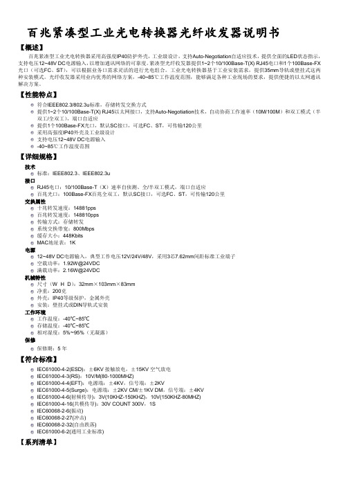
百兆紧凑型工业光电转换器光纤收发器说明书【概述】百兆紧凑型工业光电转换器采用高强度IP40防护外壳,工业级设计,支持Auto-Negotiation自适应技术,提供全面的LED状态指示,支持电压12~48V DC电源输入,以增加通讯网络的可靠度。
紧凑型光纤收发器提供1~2个10/100Base-T(X) RJ45电口和1个100Base-FX 光口(可选FC、ST),可以根据业务口需求灵活的进行光电组合。
工业光电转换器基于工业安装需求,提供35mm导轨或壁挂式这两种安装模式。
光纤收发器采用业内优秀的网络方案,-40~85℃工作温度范围,能够满足各种工业现场的要求,提供便捷的以太网通讯解决方案。
【性能特点】符合IEEE802.3/802.3u标准,存储转发交换方式提供1~2个10/100Base-T(X) RJ45以太网接口,支持Auto-Negotiation技术,自动协商工作速率(10M/100M)和双工模式(半双工/全双工),端口自适应提供1个100Base-FX光口,默认SC接口,可选FC、ST,可传输120公里采用高强度IP40外壳及工业级设计支持电压12~48V DC电源输入-40~85℃工作温度范围【详细规格】技术标准:IEEE802.3、IEEE802.3u接口RJ45电口:10/100Base-T(X)速率自侦测、全/半双工模式,端口自适应百兆光口:100Base-FX百兆全双工,默认SC接口,可选FC、ST,可传输120公里交换属性十兆转发速度:14881pps百兆转发速度:148810pps传输方式:存储转发系统交换带宽:800Mbps缓存大小:448KbitsMAC地址表:1K电源12~48V DC电源输入,典型工作电压12V/24V/48V,采用3芯7.62mm间距标准工业端子空载功率:1.92W@24VDC满载功率:2.16W@24VDC机械特性尺寸(W×H×D):32mm×103mm×83mm净重:200克外壳:IP40等级保护,金属外壳安装:壁挂式或DIN导轨式安装工作环境工作温度:-40℃~85℃存储温度:-40℃~85℃相对湿度:5%~95%(无凝露)保修保修期:5年【符合标准】IEC61000-4-2(ESD):±6KV接触放电,±15KV空气放电IEC61000-4-3(RS):10V/M(80-1000MHZ)IEC61000-4-4(EFT):电源端:±4KV,信号端:±2KVIEC61000-4-5(Surge):电源端:±2KV CM/±1KV DM,信号端:±4KVIEC61000-4-6(射频传导):3V(10KHZ-150KHZ),10V(150KHZ-80MHZ)IEC61000-4-16(共模传导):30V COUNT 300V,1SIEC60068-2-6(振动)IEC60068-2-27(冲击)IEC60068-2-32(自由跌落)IEC61000-6-2(通用工业标准)【系列清单】【产品外观】Ck1011 Ck1021 【LED 指示灯】【接地和电源连接】设备接地:转换器上侧板出有一接地螺丝,此点连接接地线的一端,另一端需可靠接入机房的大地。
d-link 百兆单模收发器 操作指南说明书
技术支持办公地址:北京市朝阳区安定路39号长新大厦7层703-704室技术支持中心电话:4006-828-828各地维修中心地址请登录客方网站查询网址:400电话工作时间:工作日9:00-19:00;节假日:9:00-18:00操作指南百兆单模收发器物品清单:●一个光纤收发器●一个电源适配器●一本快速安装指南使用说明:DFE-162SA与DFE-162SB须配套使用.光纤收发器发射波长接收波长传输距离DFE-162SA 1310nm 1550nm 20kmDFE-162SB 1550nm 1310nm 20km友讯电子设备(上海)有限公司(了解更多D-Link光电产品请扫描二维码)第一版(2019年06月)中国制造RECYCLABLELED 指示具体含义如下:LED指示灯状态说明FX 亮光口连接正常闪烁光口有数据传输UTP亮电口连接正常闪烁电口有数据传输PWR 亮电源正常正确连接完成后,光纤收发器不需要进行任何设置。
规格参数硬件连接:一、保修信息:1凡属正常使用情况下由于产品本身质量问题引起的故障,在保修期内D-Link公司将负责给予有限保修。
2、产品出现故障,请直接送至就近的D-Link修中心。
D-Link公司在全国各大中城市设有维修中心,将为用户提供高效、优质的服务,具体联系方式请见,官方网站3、产品的保修期以D-link公司在中国发布该产品时宣布的保修期为准,详情请查阅4、若对所选购的产品有超出标准保修外的需求,欢迎查询“延保、续保服务介绍”二、保外条款:以下情况不属于保修范围1、非硬件或版本的技术问题2、机器浸水、运输、装卸、震裂、碰撞、使用后所产生的污渍或表面划伤等其他非正常使用原因造成的故障或损环3、擅自拆机,改装或产品经过非我公司所属成者授权服务中心技术人员维修或拆装4、非产品所规定的工作环境下使用造成的故障或损坏(例如温度过高、过低、过于潮湿或干燥,海拔过高,电压或电流不稳定,零地电压过人等等)5、由于不可抗拒(如火灾、地震,等)或自然灾害(如雷击)所造成的故障或损坏6、由于用户或第三方误用或不正确的安装调试造成的故或损环7、无D-Link标识、产品序列号,易碎标签等信息无法识別、被删除、篡改的情况之一的8、非区域内合法经销渠道所购买产品9、产品出保修期三、保修适用范国:中国,不包括香港、澳门特别行政区和台湾地区四、警示:1、上述各条款规定了D-Link公同对产品的所有责任,并取代其他一切明示、暗示的保证和/或责任。
台式SOT-10-100M-204产品手册

类型
数量
10/100Base-FX
2
备注 支持光口 1+1 保护
以太网口 l 符合 IEEE802.3 标准。 l 提供 4 个标准的 RJ45 双绞线接口。
光口 l 符合 100Base-Fx 标准 l 发光功率:-4 至-14dBm。 l 接收灵敏度:优于-36dBm。 l 动态范围:优于 25dB。 l 工作波长:1310nm(可选 850nm/1550nm) 。 l 光口连接器类型:SC 型(FC 型可选)。 l 传输距离:0~40Km(单模) ,0~5Km(多模)。 注1:传输距离与实际使用光纤的损耗、光纤接续损耗以及其它影响光纤线路质量的指标有
3 面板说明 3.1 前面板及实物图
图 1 SOT-10/100M-204 面板示意图
图 2 SOT-10/100M-204 前视图
地址:江西九江市庐山区工业园安平路 1010 号 电话:0792-8376677 传真:8360566
2
3.2 端口说明
SOT-10/100M-204 提供 4 个百兆 FE 口,可以设置成交换或隔离状态,同时提供 2 路光口,可
3.4 保护倒换应用说明
保护倒换功能自动开启,必须同时连接好两个光口,保护倒换才可实现。
两光口同时连接时,默认光口 1 主用(传输业务),默认光口 2 备用(保护光口 1),光口 1LinkDown 时,业务自动倒换至光口 2,。此时,若光口 1 再次 LinkUp,业务不会自动倒换至光口 1,光口 2LinkDown 时,业务才会自动倒换至光口 1,。即:仅当主用光口 LinkDown 时,才会自动倒换。
1
绿色 光口 1 连接状态指示灯
2
绿色 光口 2 连接状态指示灯
B&TON收发器资料
光口链接/状态指示灯
FX LINK/ACT
光口链接/状态指示灯
FDX TX-100 TX LINK/ACT
光口工作模式指示灯
电口信号 指示灯
电链接/状态 指示灯
状态 亮 灭 亮 灭 亮 闪烁 灭 亮 灭 亮 灭 亮 闪烁 灭
安装与连接
1.光纤收发器一般成对使用。典型的连接如下图所示:
工作情况 有电 无电
观以实物为准)如:
图 2-2 各类型光纤收发器面板结构图
-4-
指示灯状态说明
深圳市百通伟业科技有限公司
表 5.1 光纤收发器指示灯说明
指示灯 PWR
功能 电源指示灯
FX
光口链接/状态指示灯
FX LINK/ACT
光口链接/状态指示灯
TX-1000
TX LINK/ACT
电口信号 指示灯 电链接/状态 指示灯
4.首先确认设备的输入额定电压是 220V 还是-48V,然后接通对应的电源后,如 PWR 亮,表示供电正常。
七、技术参数
表 7.1 相关指标与参数
项目 线缆类型 传输类型 传输方式
MTBF 误码率 数据缓存器 功率稳定率 光功率接收动态范围(DBm)
工作温度 储存温度 最大电流
功耗 兼容性 EMC 体积
-5-
深圳市百通伟业科技有限公司
未开机等),则只有 FDX 指示灯亮。 技术参数
● 标准: IEEE 802.3z/AB 1000Base-T/SX/LX/ZX ● 接口: 双绞线: RJ45
光纤: SC、ST 或 FC LED: PWR, FX Link/ACT,FDX,TX-100,
TX Link/ACT,FX-100 ● 传输速率: 双绞线: 10/100/1000Mbps
可远端管理型以太网光纤收发器 说明书

10/100M、10/100/1000M可远端管理型以太网光纤收发器用户使用手册安全注意事项在安装和使用本设备之前,请仔细阅读以下事项,我公司不对任何由于违反安全事项造成的损失承担责任。
光电转换器输出为不可见激光辐射,光口发射的激光可能对人眼造成一定的损害,任何时候不要向光口望去,不使用光口时,请插入光模块堵头。
光电转换器为集成化设备,内含精密器件,为避免严重冲击对其构成损害,请避免剧烈振动和碰撞,请自行拆卸或维修,在我公司技术人员同意和指导下需要拆卸或维修时,必须按照防静电程序进行操作。
为保护设备的安全与运行稳定性,在使用本设备时须提供良好的接地保护。
请勿擅自拆卸光电转换器,否则将可能造成不可恢复的损失。
我公司将擅自拆卸设备为自动放弃保修权力。
目录第一章 网管系统功能介绍--------------------------------------------------------------------1第二章 网管型光纤收发器硬件使用说明--------------------------------------------------2 一.网管卡使用说明------------------------------------------------------------------------2二.级联卡使用说明------------------------------------------------------------------------3三. 10M/100M光纤收发器卡使用说明-------------------------------------------------4四. 10M/100M/1000M光纤收发器卡使用说明---------------------------------------5五.网管机架使用说明---------------------------------------------------------------------6六.技术参数---------------------------------------------------------------------------------7第三章 网管型光纤收发器软件使用说明--------------------------------------------------8 一硬件平台及软件环境-------------------------------------------------------------------8二 安装管理软件---------------------------------------------------8三SNMP管理软件的使用说明----------------------------------------------------------11四WEB管理软件的使用说明-----------------------------------------------------------19五FTP使用说明 --------------------------------------------------------------------------22六CONSOLE使用说明 ------------------------------------------------------------------24第四章常见故障解答 --------------------------------------------------------------------------25第一章网管系统功能介绍10/100M、10/100/1000M可远端管理型光纤收发器是款高可靠、低成本的以太网传输媒体转换器,其作用是高效率地实现10M、100M、1000M以太网电口和光口之间的转换。
光纤收发器百兆英文说明书

Copyright statementThis publication may not be reproduced as a whole or in part, any way whatsoever unless prior consent has been obtained from us.FCC warningThe media converter have been tested and found to comply with the limits for a Class A digital device ,pursuant to Part 15 of the FCC Rules .These standards are designed to provide reasonable protection against harmful interference when these devices are operated in commercial environment These devices can use ,generate and radiate radio frequency energy and may cause harmful interface to radio communications unless installed in accordance with this User’s Guide .Operation of this device in a residential area is likely to cause harmful interface which will make the user responsible for the appropriate remedial action at his/her own expense.CE mark WarningThese are Class A products. In a domestic environment these products may cause radio interface in which case the user will need to consider adequate preventative measures.Package ContentThank you for purchasing our Ethernet Media Converter. Before you start installing the Media Converter, verify the following items in the packageMedia ConverterUser’s ManualPower AdapterThe Media Converter makes it possible to mix network media to optimize total cost of ownership when you are extending legacy twisted-pair network to a fiber-optic backbone. , It is primarily designed for larger and higher bandwidth demanding workgroups that require expansion of the Ethernet network. The media Converter features a RJ45 jack and an ST/SC/FC fiber optic connectors, connecting the10/100Mbps network to the 100BASE-FX (fiber optic) network. At full duplex mode, the converter can extend distance up to 2 kilometers for Multi-mode fiber and up to 100 kilometers for Single-mode fiber., maximize conversion options and network design flexibilityFeaturesCompliant with IEEE802.3 10Base-T, and IEEE802.3u 100Base-TX/FX standards·Support auto-negotiation function in TP port to detect speed (10/100M) and duplex mode (full/half) automatically·Support auto uplink (auto MDI/MDI-X) in TP port, no more cross-over cable·Extend fiber-optic distance up to 100km with single-mode fiber·Provide various fiber-optic interfaces with ST/SC/FC connectors·Mountable in the converter chassisInstallationAs with any electric device, you should place the equipment where it will not be subject to extreme temperatures, humidity, or electromagnetic interference. Specifically, the site you select should meet the following requirements:Please follow the steps to install the media converter. This Converter is a plug-and-play device.1. Turn off the power of the device/station in the network in which the media converter will be installed.2. Ensure that there is no activity in the network.3.Attached fiber cable from the media converter to the fiber network. The fiber connections must be matched—Transmit socket to receive socket4.Attached a UTP cable from the 100Base-Tx network to the RJ-45 port on the5.Connect the power cord to the the media converter and check if the power LED lights up. The TP Link and FX link LEDs will light when all the cable connections are satisfactory.6.Turn on the power of the device/station.10/100TX to 100FX ConverterThis converter provides one TX port and one FX port. For the FX port, it provides options of either multi-mode or single-mode fiber accommodatingST/SC/FC connector. For the TX port, it uses RJ-45 connector supports auto senses the speed of 10/100Mbps.New features support Auto Uplink on TX port and LFPT(Link-Fault-Pass-Through).Auto Uplink: User can connect to PC or switch/hub by using eitherstraight-through or cross-over cable. It will automatically detect the type of cable and link the connection.Link Fault Pass-Through: When cable in one end is OUT(disconnected/damaged/at fault), it will inform the other end by turning OFF the remote end's link LEDs.1.Cable Connection of the media converterPort type Cable Type Max.Length10/100BASE-T Cat.3.4.5 UTP. RJ-45 100 meters100BASE-FX Single-mode Fiber of 1300nm (9 or 10/125µm) 15∽100kmLED IndicationPlease refer to the following table for LED indication of MC-0110 SeriesLED Status IndicationFEF Steady Lit when local FX port receive signal from remote port Off NO receiptionSPD Steady When PT data rtansmission speed is 100M Off When PT data rtansmission speed is 10M Flashing Collision occurredOff Connection in half-duplex modePhysical DescriptionTypical Optical Power Budget。
10M 100M光纤收发器 XTR100B系列 说明书

用户手册
型号:XTR100B系列
深圳市信渝达科技开发有限公司
Howfflink XTR100B 系列光收发器说明书
XTR100B系列 光收发器说明书
目录 1、产品介绍……………………………………………..…………3 2、产品特性…………………………………………..………..…3 3、网络电缆…………………………………………..…..………3 4、包装清单…………………………..…………………..………4 5、外观指示………………………………………………........4 6、安装指南…………………………………….……………..….6 7、产品技术规格……………….………… -
Howfflink XTR100B 系列光收发器说明书
(图1) FX-LINK/ACT(绿色): "常亮" 表明光纤端口链接有效,“闪烁”
表明收发器正在从光纤连接器接收数据。 FX-FDX(绿色): "常亮" 表明光纤端口工作于全双工模式;"闪烁"
单模光纤最大传输距离20/40/60/80千米(不同型号而定)。 (5) 提供电源、光纤和UTP端口状态指示灯。 (6) 内置直流电源(5.0V); 外接 220V电源.
三、网络电缆
XTR100B系列收发器支持下列连接器和网络电缆: RJ-45连接器:5类双绞线 SC光纤连接器: 多模光纤:1300nm 62.5/125,50/125um ; 单模光纤:1300nm 9/125um ; 1550nm 9/125um .
体积
150x116x33mm(LxWxH)
网址: - 第 8 页 -
网络 设备 B
(图3) 光纤收发器的典型应用1 典型应用 2:
格林威尔光纤收发器说明书

一、FT3-CFE-AAAHB卡式光纤收发器1.1.1 10/100M自适应光纤收发器业务盘(FT3-FE)FT3-FE业务盘是GFT2000的插卡式用户盘之一。
主要完成电口以太网到光口以太网的媒质转换。
电口提供10/100M以太网接口,光口100M全双工模式。
1.1.1.1 FT3-FE前面板图5-12 FT3-FE面板1.1.1.2 指示灯说明指示灯名称意义正常工作状态PWR电源指示绿灯,电源指示。
亮:有电。
灭:没有上电。
FX-LINK光口LINK 绿灯,亮:光口LINK。
灭:光口没有LINK。
TX-ACT 电口以太网收发指示绿灯,电口以太网收发指示。
闪亮:以太网电口有数据收发。
灭:电口没有数据收发。
FX-ACT光口收发指示绿灯,光口以太网收发指示。
闪亮:以太网光口有数据收发。
灭:光口没有数据收发。
10/100M10M/100M指示黄绿双色,10M/100M指示。
绿灯亮:100M。
黄灯亮:10M。
灭:电口没有link。
H/F全半双工指示黄绿双色。
绿灯亮:以太网工作在全双工方式。
灭:以太网工作在半双工方式。
黄灯亮:表示以太网半双工方式发生碰撞。
1.1.1.3 FT3-FE拨码开关FT3-FE的可以通过拨码开关S1对以太网电口进行设置图5-13 拨码开关位置拨码开关含义拨位号OFF ON1 AutoEn/ AutoDis自动协商强制设置2 Full/Half全双工半双工3 100M/10M100M速率10M速率4 Soft / Hard软件网管配置硬件拨码开关配置□AutoEn/ AutoDis 拨到OFF时FT3-FE与连接设备通过自动协商确定速率和全半双工,此时开关2,3位无效。
当AutoEn/ AutoDis 拨到ON时通过2,3位开关确定FT3-FE的速率和全半双工。
□Full/Half设置以太网电接口的全双工□100M/10M设置以太网电接口的速率□Soft/ Hard拨到OFF时以太网电接口由网管软件配置,Soft/ Hard拨到ON时以太网电接口由第1-3位拨码开关配置。
亿兆未来MST100系列光纤收发器用户手册

图 4-4 MST100(S)-2/D 后面板图
图 4-5 KMST100(S)-1/D/2 面板图
MST100(S)-1/2/D 机壳:长 宽 高(mm): 157 88 42(内置电源)
设备功能 KMST100(S)-1/2/D 面板:高 宽(mm): 178 21
面板开关及接插件
MST100(S)设备的机壳前面板如图 5.1-1,MST100(S)-2/D 设备的机壳前面板如图 5.1-2,
要求进行操作请注意安全标识。并保存好本手册,以备将来参考用。
文档说明:
本用户手册根据中华人民共和国通信行业标准,并结合本公司 MST100 系列
设备实际情况编写,为 MST100 系列设备使用者提供参考。
日期
版本
说明
2012 年 12 月
V1.0
本用户手册更新
标志说明:
本书采用各种醒目标志来表示在安装操作过程中应该特别注意的地方,这 些标志的意义如下:
8. 主要技术参数 ............................... 13
8.1 相关标准 .............................. 13 8.2 基本特性 .............................. 13 8.3 光接口特性 ............................ 13 8.4 以太网接口指标 ........................ 13 8.5 供电条件 .............................. 13 8.6 工作环境 .............................. 13 8.7 设备质量 .............................. 13
光纤收发器使用说明
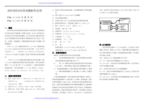
双纤双向光纤收发器使用说明中性10/100M 多模系列中性10/100M 单模系列一.概述双纤双向光纤收发器是用来将以太网的电信号转换成光信号的光电信号转换器,它的特点是用一对(芯)光纤就可以同步进行光信号的发送和接收,由于信号是以光脉冲的形式在光千种传输信号所以其相对于铜导线有许多又优点:安全性,可靠性,传输速度,传输距离都非常适用于局域网,城域网组网。
中性10/100M多模系列和中性10/100M单模系列是10/100M自适应双纤双向光纤收发器,它完全符合IEEE802.3, IEEE802.3u,10BaseT,100BaseTX, 100Base-FX标准。
并已通过了信息产业部电信设备进网测试中性10/100M多模系列是多模百兆双纤收发器;中性10/100M单模系列是单模百兆双纤收发器。
双纤双向收发器有1个RJ45接口和1个SC单芯接口,分别用来连接双绞线和光纤。
单纤收发器有6个LED指示灯:POWER、TX100、FX100、FX Link/Act、TX Link/Act、Fdx。
二.规格与特性说明△:符合 IEEE 802.3 IEEE 802.3u IEEE 802.3X IEEE802.1Q 100BASE-TX,100BASE-TX, 100Base-FX 标准△:支持TCP/IP、PPPOE、DHCP、ICMP、NAT协议△:流控方式:全双工采用IEEE 802.3X,半双工采用Backpressure标准△:电端口支持自动协商功能,自动调整传输方式和传输速度△:端口支持Auto-MDI/MDIX自动翻转△:支持存储转发模式△:支持电口的10M,100M模式或自适应模式的切换△:提供状态指示灯,外置电源(输出5V~50HZ 1A)△:接口: 电气口: RJ45 光纤口: SC△:双绞线: 超5类,6类△:多模光纤: 50/125,62.5/125µm△:单模光纤: 8/125,8.3/125, 9/125µm△:工作温度: 0 ~ 50℃△:存储温度: -20 ~ 70℃△:湿度: 5% ~ 90%△:体积:电源外置式:26×70×94mm(高×宽×长)电源内置式:30×110×140mm(高×宽×长)三.安装和初始化请按以下步骤安装单纤双向光纤收发器:a)将光纤跳线或尾纤从同一对光纤两端的光纤终端盒分别连接到远端收发器的SC口。
10M100M(4口)光纤收发器说明书

四口10/100M光纤收发器用户手册○Z感谢阁下购买本公司产品,在使用之前请详细阅读本用户手册。
注意本手册任何部分不得复印,翻制或以任何形式在网络中发送,除非得到本公司的书面许可。
本公司有权随时更改产品性能及本手册说明而不事先通知客户。
本手册所提及的商标所有权由各商标持有人所有。
对于以任何形式修改产品及本手册说明而造成的产品功能不能实现,本公司将不负任何责任。
本公司对由合法渠道(包括授权代理)取得产品的用户提供壹年有限质保,但不包括由于操作不当,错误连接和其它人为损坏及自然灾害造成的产品损坏及人员伤害。
在质保期内由于产品本身质量而造成不能正常使用的,本公司负责回收换新。
回收的产品归本公司所有。
目录第一章概述1.1、产品概述1.2、性能特征1.3、外形尺寸1.4、电源与功率1.5、环境要求第二章开箱与安装2.1、开箱检查2.2、电源及连接2.3、安装与使用第三章机型说明3.1、发送(TV)机信号指示灯与功能接口定义3.2、接收(RV)机信号指示灯与功能接口定义3.3、机架插卡型接收机第四章典型应用第五章问题解答5.1、上电自检5.2、状态诊断5.3、故障及处理第一章概述1.1、产品概述四口10/100M光纤收发器是采用全数字无压缩技术,进行以太网传输的光通信设备。
本设备可将4路以太网等复用在同一光纤上传输。
可根据用户的实际需要进行配置,灵活实现各种组网方案,大大降低了组网成本,有效的保护了用户投资。
四口10/100M光纤收发器广泛适用于安防监控、高速公路、电子警察、自动化智能小区、海关、电力、水利、石油、化工等诸多领域。
接口功能快速浏览请见第三章。
四口10/100M光纤收发器分发送机与接收机2个系列,每个系列又各有1-4路以太网形成各种不同的具体机型,但所有机型基本外型相同,仅接口位置及数量有差异,请使用时注意辨认。
本手册以四口10/100M光纤收发器机型满配置为例加以描述,其他机型不再一一描述,均可参照本手册。
M-FAST SFP-SM LC 100Mbps 单模光纤传输器说明书

MTBF (Telecordia SR-332 Issue 3) @ 25°C: 652 Years
Operating temperature:
0-+60 °C
Storage/transport temperature:
-40-+85 °C
Relative humidity (non-condensing):
Operating Voltage: Power consumption:
power supply via the switch 1W
Software
Diagnostics:
Optical input and output power, transceiver temperature
Ambient conditions
Technical Specifications
Product description
Type: Description: Part Number: Port type and quantity:
M-FAST SFP-SM/LC SFP Fiberoptic Fast-Ethernet Transceiver SM 9nector
Scope of delivery:
SFP module
Variants
Item #
Type
943866001 M-FAST SFP-SM/LC
Update and Revision:
Revision Number: 0.55 Revision Date: 08-07-2020
© 2020 Belden, Inc
Network size - length of cable
- 1、下载文档前请自行甄别文档内容的完整性,平台不提供额外的编辑、内容补充、找答案等附加服务。
- 2、"仅部分预览"的文档,不可在线预览部分如存在完整性等问题,可反馈申请退款(可完整预览的文档不适用该条件!)。
- 3、如文档侵犯您的权益,请联系客服反馈,我们会尽快为您处理(人工客服工作时间:9:00-18:30)。
Copyright statementThis publication may not be reproduced as a whole or in part, any way whatsoever unless prior consent has been obtained from us.FCC warningThe media converter have been tested and found to comply with the limits for a Class A digital device ,pursuant to Part 15 of the FCC Rules .These standards are designed to provide reasonable protection against harmful interference when these devices are operated in commercial environment These devices can use ,generate and radiate radio frequency energy and may cause harmful interface to radio communications unless installed in accordance with this User’s Guide .Operation of this device in a residential area is likely to cause harmful interface which will make the user responsible for the appropriate remedial action at his/her own expense.CE mark WarningThese are Class A products. In a domestic environment these products may cause radio interface in which case the user will need to consider adequate preventative measures.Package ContentThank you for purchasing our Ethernet Media Converter. Before you start installing the Media Converter, verify the following items in the packageMedia ConverterUser’s ManualPower AdapterThe Media Converter makes it possible to mix network media to optimize total cost of ownership when you are extending legacy twisted-pair network to a fiber-optic backbone. , It is primarily designed for larger and higher bandwidth demanding workgroups that require expansion of the Ethernet network. The media Converter features a RJ45 jack and an ST/SC/FC fiber optic connectors, connecting the10/100Mbps network to the 100BASE-FX (fiber optic) network. At full duplex mode, the converter can extend distance up to 2 kilometers for Multi-mode fiber and up to 100 kilometers for Single-mode fiber., maximize conversion options and network design flexibilityFeaturesCompliant with IEEE802.3 10Base-T, and IEEE802.3u 100Base-TX/FX standards·Support auto-negotiation function in TP port to detect speed (10/100M) and duplex mode (full/half) automatically·Support auto uplink (auto MDI/MDI-X) in TP port, no more cross-over cable·Extend fiber-optic distance up to 100km with single-mode fiber·Provide various fiber-optic interfaces with ST/SC/FC connectors·Mountable in the converter chassisInstallationAs with any electric device, you should place the equipment where it will not be subject to extreme temperatures, humidity, or electromagnetic interference. Specifically, the site you select should meet the following requirements:Please follow the steps to install the media converter. This Converter is a plug-and-play device.1. Turn off the power of the device/station in the network in which the media converter will be installed.2. Ensure that there is no activity in the network.3.Attached fiber cable from the media converter to the fiber network. The fiber connections must be matched—Transmit socket to receive socket4.Attached a UTP cable from the 100Base-Tx network to the RJ-45 port on the5.Connect the power cord to the the media converter and check if the power LED lights up. The TP Link and FX link LEDs will light when all the cable connections are satisfactory.6.Turn on the power of the device/station.10/100TX to 100FX ConverterThis converter provides one TX port and one FX port. For the FX port, it provides options of either multi-mode or single-mode fiber accommodatingST/SC/FC connector. For the TX port, it uses RJ-45 connector supports auto senses the speed of 10/100Mbps.New features support Auto Uplink on TX port and LFPT(Link-Fault-Pass-Through).Auto Uplink: User can connect to PC or switch/hub by using eitherstraight-through or cross-over cable. It will automatically detect the type of cable and link the connection.Link Fault Pass-Through: When cable in one end is OUT(disconnected/damaged/at fault), it will inform the other end by turning OFF the remote end's link LEDs.1.Cable Connection of the media converterPort type Cable Type Max.Length10/100BASE-T Cat.3.4.5 UTP. RJ-45 100 meters100BASE-FX Single-mode Fiber of 1300nm (9 or 10/125µm) 15∽100kmLED IndicationPlease refer to the following table for LED indication of MC-0110 SeriesLED Status IndicationFEF Steady Lit when local FX port receive signal from remote port Off NO receiptionSPD Steady When PT data rtansmission speed is 100M Off When PT data rtansmission speed is 10M Flashing Collision occurredOff Connection in half-duplex modePhysical DescriptionTypical Optical Power Budget。
