PMAC9900E产品说明书_中文
PMAC9900E_modbus通讯协议
PMAC®9900E标准电量监测仪MODBUS串行通信协议ZHUHAI PILOT ELECTRONICS Co.,LtdDoc.No.03-0304-002珠海派诺电子有限公司目录第一章简介 ----------------------------------------------------------------------------------2 11串行通讯协议的目的----------------------------------------------------------21 2 MODBUS通讯协议的版本 ------------------------------------------------------2第二章PMAC®9900E-MODBUS串行通讯协议详细说明-----------------------------22 1 协议基本规则 ---------------------------------------------------------------------22 2 传送模式 ---------------------------------------------------------------------------22 3 包裹结构 ---------------------------------------------------------------------------223 1 地址域 --------------------------------------------------------------------323 2 功能码域 -----------------------------------------------------------------323 3 数据域 --------------------------------------------------------------------323 4 校验域 --------------------------------------------------------------------32 4 网络时间 ---------------------------------------------------------------------------32 5 异常响应 ---------------------------------------------------------------------------32 6 广播命令 ---------------------------------------------------------------------------4第三章通信包裹 -----------------------------------------------------------------------------43 1 16位/32位数据通讯模式 -------------------------------------------------------43 2 读寄存器包裹 -------------------------------------------------------------------43 3 写寄存器包裹 -------------------------------------------------------------------5 第四章计算CRC-16校验码----------------------------------------------------------------7 第五章 PMAC®9900E寄存器说明 -------------------------------------------------------8附录A PMAC®9900E-MODBUS寄存器表 ---------------------------------------8 附录B 符号寄存器含义 --------------------------------------------------------------13 附录C 数据单位 -----------------------------------------------------------------------13 附录A 有关继电器的操作 -----------------------------------------------------------14第六章通信包裹范例---------------------------------------------------------------------- 14第一章 简介通信协议详细地描述了PMAC®9900E在MODBUS通讯模式下的输入和输出命令信息和数据以便第三方使用和开发1 1 串行通讯协议的作用通信协议的作用使信息和数据在上位机主站和PMAC®9900E之间有效地传递它包括1允许主站访问和设定所连接PMAC®9900E的全部设置参数2允许访问PMAC®9900E的所有测量数据和事件纪录1 2 MODBUS通讯协议的版本该通讯协议适用于本公司已经出厂的所有各种版本的PMAC®9900E仪表对于日后的系列若有改动会加以特别说明第二章 PMAC®9900E-MODBUS 串行通信协议详细说明2 1 PMAC®9900E-MODBUS协议基本规则以下规则确定在RS485或者RS232C回路控制器和其他RS485串行通信回路中设备的通信规则1所有RS485回路通信应遵照主/从方式在这种方式下信息和数据在单个主站和最多32个从站监控设备之间传递2主站将初始化和控制所有在RS485通信回路上传递的信息3无论如何都不能从一个从站开始通信4所有RS485环路上的通信都以打包方式发生一个包裹就是一个简单的字符串每个字符串8位一个包裹中最多可含255个字节组成这个包裹的字节构成标准异步串行数据并按8位数据位1位停止位无校验位的方式传递串行数据流由类似于RS232C 中使用的设备产生5主站发送包裹称为请求从站发送包裹称为响应6任何情况从站只能响应主站一个请求2 2 传送模式MODBUS协议可以采用ASCII或者RTU模式传送数据PMAC®9900E仅仅支持RTU 模式8位数据位无校验位1位停止位2 3 MODBUS包裹结构描述每个MODBUS包裹都由以下几个部分组成1地址域2功能码域3数据域4校验域23 1 地址域MODBUS的从站地址域长度为一个字节包含包裹传送的从站地址有效的从站地址范围从1~247从站如果接收到一帧从站地址域信息与自身地址相符合的包裹时应当执行包裹中所包含的命令从站所响应的包裹中该域为自身地址23 2 功能码域MODBUS包裹中功能域长度为一个字节用以通知从站应当执行何操作从站响应包裹中应当包含主站所请求操作的相同功能域字节有关PMAC®9900E的功能码参照下表功能码含义功能0x03 读取寄存器获得当前PMAC®9900E内部一个或多个当前寄存器值0x10 设置寄存器将指定数值写入PMAC®9900E内部一个或多个寄存器内23 3 数据域MODBUS数据域长度不定依据其具体功能而定MODBUS数据域采用”BIG INDIAN”模式即是高位字节在前低位字节在后举例如下Example 2.11个16位寄存器包含数值为0x12AB寄存器数值发送顺序为高位字节 =0x12低位字节 =0x0AB23 4 校验域MODBUS-RTU模式采用16位CRC校验发送设备应当对包裹中的每一个数据都进行CRC16计算最后结果存放入检验域中接收设备也应当对包裹中的每一个数据除校验域以外进行CRC16计算将结果域校验域进行比较只有相同的包裹才可以被接受具体的CRC校验算法参照附录2 4 网络时间考虑在RS485网络上传送包裹需要遵循以下有关时间的规定1主站请求包裹结束到从站响应包裹开始之间的时间最小为20毫秒最大为250毫秒典型值为60毫秒2从站响应包裹结束到主站下一请求包裹开始之间的时间在16位模式下典型值为100毫秒在32位模式下典型值为500毫秒3包裹中相邻两个字节之间的最大时间依据通讯波特率不同而不同一般来说最大字节时间为3倍的字节发送时间例如9600波特率下字节间隔为3毫秒4800波特率时字节间隔为6毫秒2 5 异常响应如果主站发送了一个非法的包裹给PMAC®9900E或者是主站请求一个无效的数据寄存器时异常的数据响应就会产生这个异常数据响应由从站地址功能码故障码和校验域组成当功能码域的高比特位置为1时说明此时的数据帧为异常响应下表说明异常功能码的含义功能码该码表示从站接收到非法的功能码或者是接收到一个错误的操作密码接收到无效的数据地址或者是请求寄存器不在有效的寄存器范围内2 6 广播命令PMAC®9900E-MODBUS协议不支持广播命令第三章通讯包裹PMAC®9900E-MODBUS支持两个功能码标准的MODBUS协议仅支持16位数据模式也就说传输任何测量值最大为65535为了支持传输更大的测量值PMAC®9900E提供了扩展的32位数据模式3.1节将描述16位数据模式与32位数据模式的不同 3.2节将说明PMAC®9900E的读数据包裹和响应包裹的格式 3.3节将说明PMAC®9900E写数据包裹和响应包裹的格式3 1 16位/32位数据通讯模式16位数据模式中所有的数据都是通过一个16位寄存器表示即使实际数值超过65535但是传输的最大值只能为6553532位模式中所有的数据都是依照如下规则组织的1除电能参数以外的实时数据和设置参数都是用两个寄存器说明高位寄存器 =实际值 / 10000 商值低位寄存器 =实际值 / 10000 余数这种设定方式是为了兼容MODICON的PLC装置2符号寄存器高位寄存器固定位0低位寄存器仍然保持原有数据3电能数据不论采用16位或者32位数据模式都可以采用两个寄存器表示16位数据模式高16位 =实际值 / 1000 商值低16位 =实际值 / 1000 余数32位数据模式:高32位寄存器高16位 =0低16位 =实际值 / 1000000 商值低32位寄存器高16位 =实际值 / 10000 / 100 余数低16位 =实际值 / 10000 余数在16位数据模式下电能数据最大为65000MWH在32位数据模式下电能数据最大为2000GWH3 2 读寄存器功能码03由主站机发送的包裹请求PMAC®9900E响应所有有效的寄存器在起始寄存器和终止寄存器之间一般读寄存器不需要密码但在以下两种情况下需要正确的密码1去读一个被保护的寄存器目前唯一被保护的寄存器是保护仪表密码的寄存器2如果只读保护寄存器地址43017已设置那么密码正确才能读任何寄存器在响应包裹中仅仅有效的寄存器才能被发送PMAC®9900E没有配置的寄存器或对该输入电压模式下不存在的寄存器将不被发送由于MODBUS协议中并没有专门的密码域所以执行与密码相关的操作时需要执行一个特殊的操作首先采用写寄存器功能码将密码写入密码寄存器中地址43051无论写入密码是否正确PMAC®9900E都会做出响应此时用户在执行需要操作的功能如果先前的写入密码不正确则响应的包裹为异常如果写入密码正确则PMAC®9900E会响应正常的数据16位模式读寄存器包裹格式主机PMAC®9900E响应格式PMAC®9900E主机从站地址1字节从站地址1字节功能码03H 1字节功能码03H 1字节起始寄存器地址2字节字节数2*寄存器数目1字节寄存器个数2字节第一个寄存器数据2字节CRC校验码2字节第二个寄存器数据2字节…………CRC校验码2字节32位模式读寄存器包裹格式主机PMAC®9900E响应格式PMAC®9900E主机从站地址1字节从站地址1字节功能码03H 1字节功能码03H 1字节起始寄存器地址2字节字节数2*寄存器数目1字节寄存器个数2字节第一个寄存器数据高位字2字节CRC校验码2字节第一个寄存器数据低位字2字节第二个寄存器数据高位字2字节第二个寄存器数据低位字2字节…………CRC校验码2字节注意1响应包裹中只会包含有效的寄存器那些未配置的寄存器和无效的寄存器都不会被仪表发送上来所以用户首先要确定仪表中所配置的寄存器例如如果用户需要请求40046寄存器数据而且当前PMAC®9900E并未配置该寄存器则仪表将会将40055寄存器数据送上假定仪表在40046寄存器后配置的第一个有效寄存器是400552 32位数据模式下请求寄存器数目是16位数据模式下的2倍例如在32位模式下请求10个参数需要20个寄存器但在16位模式下只需要10个寄存器3 3 写寄存器功能码16该命令允许主站配置PMAC®9900E工作参数以下为数据格式16位模式响应格式PMAC®9900E主机写寄存器包裹格式主机PMAC®9900E从站地址1字节从站地址1字节功能码10H 1字节功能码10H 1字节起始寄存器地址2字节起始寄存器地址2字节寄存器个数2字节寄存器个数2字节1字节CRC校验码2字节字节个数2*寄存器个数第一个寄存器数据第二个寄存器数据……….CRC校验码2字节32位模式响应格式PMAC®9900E主机写寄存器包裹格式主机PMAC®9900E从站地址1字节从站地址1字节功能码10H 1字节功能码10H 1字节起始寄存器地址2字节起始寄存器地址2字节寄存器个数2字节寄存器个数2字节1字节CRC校验码2字节字节个数2*寄存器个数第一个寄存器数据高位字第一个寄存器数据低位字第二个寄存器数据高位字第二个寄存器数据低位字……….CRC校验码2字节注意1 PMAC®9900E假定写入的寄存器从第一个寄存器开始是连续的2 32位模式下写入的寄存器数目是16位模式的两倍例如在32位模式下写10个参数需要20个寄存器而在16位模式下只需要10个寄存器第四章计算CRC-16该部分将描述计算CRC-16的过程在帧中的有关的字节被义为是一串2进制数据(0,1)第16位校验和是这样得到的该串数据流被216乘然后除以发生器多项式该式以2进制表示为1100000000000101商被忽略16位的余数就是CRC的值在计算CRC-16值时全部算术运算用modulo two或者异或XOR算法按照下列步骤产生CRC-16的校验和1省略发生器最有意义的位并且把位的顺序颠倒过来形成一个新的多项式结果是1010000000000001或者16进制的A0012将全部1或者16进制FFFF装入16位寄存器3用16位寄存器中低阶字节对第一个数据字节进行XOR运算把结果存入16位寄存器4把16位寄存器向右移一位如果溢出位为1则转向第5步骤否则转向第6步骤5用新的发生器多项式对16位寄存器执行MOR运算并且把结果存入16步骤6重复步骤4直到移位8次为止7用16位寄存器的第阶字节对下一个数据字节进行XOR运算将结果存入16位寄存器8重复步骤4-7直到小包的所有字节都已经用16位寄存器执行了XOR运算为止916位寄存器的内容就是CRC-16下面的例子是对16进制的6403这个字节进行CRC计算步骤 字节 动作 寄存器 位# 移位2 初值 1111 1111 1111 11111 装入第一字节 0000 0000 0110 01003 异或 1111 1111 1001 10114 右移一位 0111 1111 1100 1101 1 15a 异或多项式 1101 1111 1100 11004 右移一位 0110 1111 1110 0110 2 04 右移一位 0011 0111 1111 0011 3 04 右移一位 0001 1011 1111 1001 4 15a 异或多项式 1011 1011 1111 10004 右移一位 0101 1101 1111 11005 04 右移一位 0010 1110 1111 1110 6 04 右移一位 0001 0111 0111 1111 7 04 右移一位 0000 1011 1011 1111 8 15a 异或多项式 1010 1011 1011 11102 装入第二字节 0000 0000 0000 00117 异或 1010 1011 1011 11014 右移一位 0101 0101 1101 1110 1 15a 异或多项式 1111 0101 1101 11114 右移一位 0111 1010 1110 1111 2 15a 异或多项式 1101 1010 1110 11104 右移一位 0110 1101 0111 0111 3 04 右移一位 0011 0110 1011 1011 4 15a 异或多项式 1001 0110 1011 10104 右移一位 0100 1011 0101 11015 04 右移一位 0010 0101 1010 1110 6 15a 异或多项式 1000 0101 1010 11114 右移一位 0100 0010 1101 0111 7 15a 异或多项式 1110 0010 1101 01104 右移一位 0111 0001 0110 1011 8 0CRC-16 0111 0001 0110 1011第五章 PMAC®9900E寄存器说明所有的PMAC®9900E寄存器包括实时寄存器和设置寄存器在MODBUS通讯协议时都具有4XXXX的基址根据MODBUS协议请求PMAC®9900E中一个地址为4XXXX 的寄存器时主站实际读取为XXXX-1例如请求PMAC®9900E中40011寄存器主站实际寄存器号为10下表说明在不同电压模式下部分实时寄存器的状态发生了变化原有的有效寄存器变为无效寄存器电压模式寄存器描述WYE DEMO 3-WIRE DELTA40011 A相电压有效无效40012 B相电压有效无效40013 C相电压有效无效40014 相电压平均值有效无效40031 A相有功功率有效无效40032 B相有功功率有效无效40033 C相有功功率有效无效40035 A相无功功率有效无效40036 B相无功功率有效无效40037 C相无功功率有效无效40039 A相功率因数有效无效40040 B相功率因数有效无效40041 C相功率因数有效无效40043 A相视在功率有效无效40044 B相视在功率有效无效40045 C相视在功率有效无效附录 A PMAC®9900E-MODBUS寄存器表格表F –1 PMAC®9900E数据寄存器寄存器号寄存器类型描述标准配置Basic可选Optical40011 RO A相相电压 Basic40012 RO B相相电压Basic40013 RO C相相电压Basic40014 RO 相电压平均值Basic40015 RO AB线电压Basic40016 RO BC线电压Basic40017 RO CA线电压Basic40018 RO 线电压平均值Basic40021 RO A相电流Basic40022 RO B相电流Basic40023 RO C相电流Basic40024 RO 相电流平均值Basic40031 RO A相有功功率Basic40032 RO B相有功功率Basic40033 RO C相有功功率Basic40034 RO 三相有功功率Basic40035 RO A相无功功率Basic40036 RO B相无功功率Basic40037 RO C相无功功率Basic40038 RO 三相无功功率Basic40039 RO A相功率因数Basic40040 RO B相功率因数Basic40041 RO C相功率因数Basic40042 RO 功率因数总计Basic40043 RO A相视在功率Basic40044 RO B相视在功率Basic40045 RO C相视在功率Basic40046 RO 三相视在功率Basic40048 RO 系统频率Basic40050 RO 符号寄存器Basic40051 RO 有功电度输入KWH Basic40052 RO 有功电度输入MWH Basic40053 RO 有功电度输出KWH Basic40054 RO 有功电度输出MWH Basic40055 RO 有功电度净值KWH Basic40056 RO 有功电度净值MWH Basic40061 RO 无功电度输入KV ARH Basic40062 RO 无功电度输入MV ARH Basic40063 RO 无功电度输出KV ARH Basic40064 RO 无功电度输出MV ARH Basic40065 RO 无功电度净值KV ARH Basic40066 RO 无功电度净值MV ARH Basic40071 RO 视在电度净值KV AH Basic40072 RO 视在电度净值MV AH Basic表 F-2 状态寄存器寄存器号寄存器类型描述标准配置Basic可选Optical40902 RO 开关量S1状态Basic 40903 RO 开关量S2状态Basic 40904 RO 开关量S3状态Basic 40905 RO 开关量S4状态Basic 40906 RW 继电器RL1状态Basic 40907 RW 继电器RL2状态Basic 40908 RW 继电器RL3状态Basic 40909 RW 继电器RL4状态Basic 40910 RW 继电器RL1控制模式Basic 40911 RW 继电器RL2控制模式Basic 40912 RW 继电器RL3控制模式Basic 40913 RW 继电器RL4控制模式Basic 40914 RW 继电器RL1延时动作时间Basic 40915 RW 继电器RL2延时动作时间Basic 40916 RW 继电器RL3延时动作时间Basic 40917 RW 继电器RL4延时动作时间Basic 40918 RW 继电器RL1延时复归时间Basic 40919 RW 继电器RL2延时复归时间Basic 40920 RW 继电器RL3延时复归时间Basic 40921 RW 继电器RL4延时复归时间Basic40922 RO 继电器RL1上限报警标志Basic 40923 RO 继电器RL1下限报警标志Basic 40924 RO 继电器RL2上限报警标志Basic 40925 RO 继电器RL2下限报警标志Basic 40926 RO 继电器RL3上限报警标志Basic 40927 RO 继电器RL3下限报警标志Basic 40928 RO 继电器RL4上限报警标志Basic 40929 RO 继电器RL4下限报警标志Basic表 F-3 特殊功能寄存器寄存器号寄存器类型描述标准配置Basic可选Optical43002 RW PT一次侧电压Basic 43003 RW PT二次侧电压Basic 43004 RW CT一次侧电流Basic43005 RW C电压输入模式0123或4Basic43006 RW 设备号Basic43007 RW 波特率300120024004800960019200Basic43008 保留43009 RW 对比度视觉调节Basic 43010 RW 密码Basic 43011 WO 复位所有最小/最大值Basic 43012 WO 复位所有时间计数器如千瓦时Basic 43013 RO 版本号Basic 43014 RO 最新版本日期Basic 43015 RO 特征码Basic 43016 RO 设备类型Basic 43017 RW 允许只读保护YES OR NOBasic 43018 保留43019 RW 1#继电器设定V A上限值Basic 43020 RW 1#继电器设定V A下限值Basic 43021 RW 1#继电器设定VB上限值Basic 43022 RW 1#继电器设定VB下限值Basic 43023 RW 1#继电器设定VC上限值Basic 43024 RW 1#继电器设定VC下限值Basic 43025 RW 1#继电器设定IA上限值Basic43027 RW 1#继电器设定IB上限值Basic 43028 RW 1#继电器设定IB下限值Basic 43029 RW 1#继电器设定IC上限值Basic 43030 RW 1#继电器设定IC下限值Basic 43031 RW 1#继电器设定频率上限值Basic 43032 RW 1#继电器设定频率下限值Basic 43033 RW 2#继电器设定V A上限值Basic 43034 RW 2#继电器设定V A下限值Basic 43035 RW 2#继电器设定VB上限值Basic 43036 RW 2#继电器设定VB下限值Basic 43037 RW 2#继电器设定VC上限值Basic 43038 RW 2#继电器设定VC下限值Basic 43039 RW 2#继电器设定IA上限值Basic 43040 RW 2#继电器设定IA下限值Basic 43041 RW 2#继电器设定IB上限值Basic 43042 RW 2#继电器设定IB下限值Basic 43043 RW 2#继电器设定IC上限值Basic 43044 RW 2#继电器设定IC下限值Basic 43045 RW 2#继电器设定频率上限值Basic 43046 RW 2#继电器设定频率下限值Basic 43047 RW 3#继电器设定V A上限值Basic 43048 RW 3#继电器设定V A下限值Basic 43049 RW 3#继电器设定VB上限值Basic 43050 RW 3#继电器设定VB下限值Basic 43051 RW 3#继电器设定VC上限值Basic 43052 RW 3#继电器设定VC下限值Basic 43053 RW 3#继电器设定IA上限值Basic 43054 RW 3#继电器设定IA下限值Basic 43055 RW 3#继电器设定IB上限值Basic 43056 RW 3#继电器设定IB下限值Basic 43057 RW 3#继电器设定IC上限值Basic 43058 RW 3#继电器设定IC下限值Basic 43059 RW 3#继电器设定频率上限值Basic 43060 RW 3#继电器设定频率下限值Basic 43061 RW 4#继电器设定V A上限值Basic 43062 RW 4#继电器设定V A下限值Basic 43063 RW 4#继电器设定VB上限值Basic 43064 RW 4#继电器设定VB下限值Basic43066 RW 4#继电器设定VC下限值Basic43067 RW 4#继电器设定IA上限值Basic43068 RW 4#继电器设定IA下限值Basic43069 RW 4#继电器设定IB上限值Basic43070 RW 4#继电器设定IB下限值Basic43071 RW 4#继电器设定IC上限值Basic43072 RW 4#继电器设定IC下限值Basic43073 RW 4#继电器设定频率上限值Basic43074 RW 4#继电器设定频率下限值Basic注意对PMAC®9900E_rly2而言, 如果读到和#3#4继电器相关的寄存器PMAC®9900E将返回数据0附录 B 符号寄存器含义由于MODBUS数据为16位无符号字所以当用户需要判断功率以及电度的正负情况时就必须借助于符号寄存器40050进行以下为符号寄存器的定义位号寄存器位号寄存器D0 40031 D1 40032D2 40033 D3 40034D4 40035 D5 40036D6 40037 D7 40038D8 40039 D9 40040D10 40041 D11 40042D12 无效D13 无效D14 40055,40056 D15 40065,40066相应位为1说明对应的寄存器数据符号为负为0说明为正附录C 数据单位标准PMAC®9900E协议中的各项实时数据单位如下表所示用户解释数据时请参照名称单位分辨率电压伏特1V电流安培1A有功功率千瓦1KW无功功率千乏1KVar视在功率千伏安1KV A功率因数0.001频率赫兹0.1Hz有功电度千瓦小时1KWH无功电度千乏小时1KvarH视在电度千伏安小时1KV AH继电器延时时间秒1S附录D 有关继电器的操作PMAC®9900E通讯协议可以直接控制仪表继电器的工作状态和设置继电器的定值参数以下说明与继电器控制有关寄存器的含义1继电器状态寄存器该寄存器可读可写读时反映当前继电器的闭合或断开状态写时可以直接操作继电器的闭合和断开用户如果远端控制继电器时可以直接操作该寄存器一旦直接操作状态寄存器则继电器进入手动模式2继电器模式寄存器该寄存器可读可写反映当前继电器的控制是处于手动模式还是自动模式有关的定义参照仪表说明书数值为1表示继电器为手动模式为0表示继电器为自动模式手动模式下有关继电器的编程参数不再发挥作用3继电器报警标志寄存器该寄存器只能读当继电器处于自动模式下有效反映由于何种监测参数出现异常产生继电器动作具体的定义如下D6 D5 D4 D3 D2 D1 D0频率C相电流B相电流A相电流C相电压B相电压A相电压相应位为1表示该参量报警为0表示无报警信息第六章通信包裹范例以下采用几个实际的PMAC®9900E通讯范例说明协议的格式要求6.1 读寄存器范例1这是一个从主站向设备号UNIT为100的PMAC®9900E读请求的范例请求从40011寄存器开始连续20个寄存器数PMAC®9900E设置工作于DEMO模式三相四线星形和三相三线星形格式相同寄存器设置为16位模式主站请求地址功能域起始地址寄存器数目CRC校验64 03 000A 0014 6C32PMAC®9900E响应地址功能码字节数目40011 40012 4001364 03 10 015F 015F 015F40014 40015 40016 40017 40018 40021 015F 0260 0260 0260 0260 03EE 40022 40023 40024 40031 40032 40033 03EE 03EE 03EE 0144 0144 0144 40034 40035 40036 40037 40038 CRC校验03CC 008C 008C 008C 01A4 DB54注意请求连续的寄存器时如果其中包含有无效寄存器PMAC®9900E响应包裹将跳过无效寄存器顺序返回以同等个数的相临有效寄存器中数据6.2 读寄存器范例2这是一个从主站向设备号UNIT为100的PMAC®9900E读请求的范例请求从40011寄存器开始连续20个寄存器数PMAC®9900E设置工作于三角形模式寄存器设置为16位模式主站请求地址功能域起始地址寄存器数目CRC校验64 03 000A 0014 6C32PMAC®9900E响应地址功能码字节数目40015 40016 4001764 03 10 0000 0000 000040018 40021 40022 40023 40024 40034 0000 0000 0000 0000 0000 0000 40038 40042 40046 40048 40050 40051 0000 0000 0000 0000 0F00 029B 40052 40053 40054 40055 40056 CRC校验002F 0000 0000 029B 002F 8840注意请求连续的寄存器时如果从无效寄存器开始请求PMAC®9900E响应包裹将跳过无效寄存器从相临的有效寄存器开始返回同等个数的寄存器数据6.3 读寄存器范例3这是一个从主站向设备号UNIT为100的PMAC®9900E读请求的范例读取从40902到409094个开关量和4个继电器的状态PMAC®9900E设置工作于DEMO模式其他模式相同寄存器设置为16位模式主站请求地址功能域起始地址寄存器数目CRC校验64 03 0385 0008 5C54PMAC®9900E响应地址功能码字节数目40902 40903 4090464 03 10 0000 0000 000040905 40906 40907 40908 40909 CRC校验0000 0000 0000 0000 0000 B69D6.4 写寄存器范例1这是一个写寄存器范例来设置继电器的状态UNIT ID 100主站将写以下信息到PMAC®9900寄存器设置为16位模式1#继电器状态00002#继电器状态0001远程操作3#继电器状态00004#继电器状态0000从主站写命令地址功能码起始地址寄存器数目字节数目40906 4090764 10 0389 0004 08 0000 0001 40908 40909 CRC校验0000 0000 3530从PMAC®9900E响应地址功能域起始地址寄存器数目CRC校验64 10 0389 0004 19916.5 写寄存器范例2这是一个写寄存器范例来设置电压量程电流量程和仪表的电压模式UNIT ID 100主站将写以下信息到PMAC®9900寄存器设置为16位模式PT初级电压1200PT次级电压120CT初级电流5000电压模式0从主站写命令地址功能码起始地址寄存器数目字节数目43002 4300364 10 0BB9 0004 08 04B0 0078 43004 43005 CRC校验0388 0000 C7A4从PMAC®9900E响应地址功能域起始地址寄存器数目CRC校验64 10 0BB9 0004 1BFE。
智能电力监测仪使用说明书

3.2.4
电能参数显示在“电压-电流”栏旁边的“电能参数”栏,“功能”键用于查看2个标准的电能参数及其它选项的电能参数,按“功能”键将依次选择每个电能参数,所有功能选择完毕,显示将循环到第一个功能状态。
1、功能或相显示消失
图2.7.1RS485通讯连接
2.8
精度漂移为每年0.1%。精度校验时间间隔由用户的精度要求决定。有关精度校验请与本公司联系。
2.9
仪表发生故障一般采用整机更换的方法,但在初次安装时应作好以下工作,以保证维护尽可能方便。
1、应提供一个CT短接盒,这样使PMAC9900的电流输入不连接时,不会使CT开路,短接盒接线应使保护继电器的功能不受影响。
两个按键用于显示参数选项。
2)编程模式:存取所有设置参数。
打开电源时,PMAC9900为显示模式,并按“伏特-安培-电能参数”显示。
图3.2.1 PMAC9900面板图
注意:1、在有的情况下,一个电能参数要求有许多有效位的数或字符才能清楚地表达,这时,电能参数不能同电压(伏特)和电流(安培)同时显示,“电能参数”栏显示为空白。
2.5
图2.5.1到2.5.4为4线和3线Y型系统接线图。PMAC9900检测各相线对地的电压,如果监测是100V-347V系统,输入可以直接连接(如图2.5.1)。
PMAC9900仪表上的VOLTS MODE应设置为:4 WIRE WYE。
图2.5.14线Y型:3个元件直接连接(对100/173~347/600V系统)
1.试验盒端子:
RS485通讯线应布置在安全和容易查找的地方;通讯线应终止在试验盒(端子排)(如图2.8.1)以便于简化现场测试和诊断。
PMAC9900产品说明书

简单实用
PMAC®9900 采用了许多简化实用的设计 安装
根据用户指定数据进行设备整定 显示单元采用正面安装模式 安装深度布 超过 30mm
PMAC®9900 标准电量监测仪
3
测量
说明
PMAC®9900 按操作要求来显示测量值 显 示一次回路的电量参数为 电压
1 编程密码 该菜单要求用户输入正确的设备密码 在用 户未输入任何密码之前 显示如下
不同的工作模式下显示的具体电能参数项 目也会有所不同 用户可以参考实际的仪表 显示项目为准
当前状态下 光标键无效 按动增加键一次 出现以下显示 起始显示数值为 0
编程模式
用户在数据模式下时 同时将相序键和功能 键按下持续 2 秒钟左右 会出现如下显示 表明进入了编程模式
注意 PMAC®9900 标准型号是可以满足大部分现 场需求的 但在某些特殊场合下 例如在一 些发电厂中会采用 B 相接地系统 还有部分 现场会采用三相五线系统 这样就要求仪表 的中性点和地相分离 所以 PMAC®9900 提 供了一种改进型号以满足这些现场的需求 用户在设计时请注意选择适当的规格型号
测量相电压 Va Vb 和 Vc 以及平均值 测量或计算线电压 Uab Ubc 和 Uca 以及 平均值
电流 测量电流 Ia Ib 和 Ic 以及平均值
有功功率 计算三相有功功率 Pa Pb Pc 以及总和
电压测量
当系统电压等级小于 347V 相 /600V 线 时 PMAC®9900 电压测量回路可以直接接 入系统
PILOT® ELECTRONIC
PMAC®9900 标准电量监测仪 说明书
Installation & Operation Manual
GE Healthcare OEC 9900 Elite产品说明书

GE HealthcareDiscover the clear difference.All the special features you’ve come toassociate with OEC C-arms are residenton this latest generation C-arm, butwe’re taking the 9900 Elite to new heights.We’ve given you new features that canpositively impact your outcomes andenhance your productivity, while providingbetter return on your investment. Justwhat you’d expect from a recognizedmarket leader in mobile imagingtechnology for over 30 years.Come with us on a journey to discover thenew 9900 Elite’s superb imaging features.For over three decades,GE OEC has been amarket leader inmobile C-arm surgicalimaging. Now, theOEC 9900 Elite raisesthe mobile C-armstandard with PrecisionImaging Technologyusing DRM –DynamicRange Management.vascular productivity.Streamline eveStandard non-motorized C-arm offers superb mechanical design usingPremium 1k 2 High Resolution ImagingDigital Subtraction Roadmapping Iris Collimation Dual-Leaf CollimationSpine image withoutcollimator and Smart Window Image with Smart Window Metal Introduced Smart Metal EnabledNormal Digital Zoom Realtime Edge EnhancementImage I.Q.During live fl uoro, invisible AutoTraksampling window automatically moveswith the anatomy, ensuring superbimages no matter the position ofcollimation or centering.AutoTrakMoveable 18”Flat Panel Monitors• DICOM 3.0 internalinterface with Query andRetrieve standard.*• On-board DVD/CD Readand Write capability.• On-board Paper or HardCopy Film Option.Easy Archiving &DocumentationOEC ®9900 Elite....the cle • Twice the resolution.• Four times the information.21k 2 High ResolutionImaging • Standard High ResolutionBlack and White brightmonitors for superbfl uoroscopic viewing.• 700 Cd/m 2 maximumbrightness.• Optional right hand colormonitor for side-by-sideendoscopic and Black andWhite fl uoro images.• Advanced articulationmakes monitors visiblefrom all four sides.* DICOM options vary outside the United States.Physician Controlled X-ray Footswitch & Handswitch1k 2High ResolutionImaging Chain ear difference.C-arm Controls• Operation from eitherside of the system.Collision DetectionBumper forPatient Safetyon MD confi guration• High Resolution 9” (23 cm)or 12” (31 cm) Tri-ModeIntensifi er.- 9”, 6”, 4.5” (23, 15, 11 cm)- 12”, 9”, 6” (31, 23, 15 cm)15 kW Generator forPulsed CineBolus Chasing• 15 and 30 ppswith up to 150 mAfor high poweredpulse mode tostop motion orfreeze motion.• Generator isseparated fromthe X-ray tubeto provide highpower withoutincreasing X-raytube housingheat, improvingcooling effi ciency.High Power Rotating Anode X-ray Tube • High heat capacity X-ray tube with cooling system for long fl uoro on-times.• Fluoro• HLF High Level Fluoro• Digital Spot• Roadmap• Digital Subtraction• Low Dose ModePrecision Imaging...The DRM AdvantageProfi le Conventional OEC Image OEC 9900 Elite Image GeneralOrthopedicSpineVascularBolus ChaseCardiacvery procedure.working for you and your patients.training that can be shared with yourOur dedicated team of more than 200Field Service Engineers is made up offocused experts dedicated to servicingrst timerst time).Having engineers in all 50 states and a30-minute call-back commitment meanswe’re there for you when you need us.OEC systems maintained and running atpeak performance are better for you andperformance, choose the service offering*ts your needs. Our full-service,Primary Care coverage boasts a 97%preventative maintenance and offersconnectivity and unlimited parts andlabor features. Limited Service coverageis also available and provides technicalphone support, back-up on-site support* Service options may vary outside the United States.LR-990018-01©2008 General Electric Company – All rights reserved.General Electric Company reserves the right to make changes in specifi cations and features shown herein, or discontinuethe product described at any time without notice or obligation. Contact your GE Representative for the most current information.GE, GE Monogram and OEC 9900 Elite are trademarks of General Electric Company. GE OEC Medical Systems, Inc.Healthcare Re-imaginedGE is dedicated to helping you transformhealthcare delivery by driving criticalbreakthroughs in biology and technology. Our expertise in medical imaging and information technologies, medical diagnostics, patientmonitoring systems, drug discovery, andbiopharmaceutical manufacturing technologies is enabling healthcare professionals around the world discover new ways to predict, diagnose and treat disease earlier. We call this model of care “Early Health.” The goal: to help clinicians detect disease earlier, access more information and interveneearlier with more targeted treatments, so they can help their patients live their lives to the fullest. Re-think, Re-discover, Re-invent, Re-imagine.imagination at workg GE Healthcare,Surgery — Americas:Phone 801-328-9300Fax 801-328-4300GE Healthcare — Europe: Paris, FranceFax 33-1-30-70-94-35GE Healthcare — Asia:Tokyo, Japan —Fax: +81-452-85-5490Hong Kong —Fax: +852-2559-3588。
Signet 9900 H COMM Module Instruction Sheet说明书

*3-9900.094*For complete product information, please download the full 9900 Transmitter manual at Signet 9900 H COMM Module Instruction Sheet 3-9900.094 Rev. 4 05/18The H COMM Module enables communication between the 9900 and a HART ®-enabled device. The HART (H ighway A ddressable R emoteT ransducer) Protocol superimposes digital signals on top of the 4 to 20 mA analog signal.NOTE: With H COMM Module installed, a minimum of 24 V is required for loop-powered systems.EnglishInstallationIf the 9900 Base Unit will be mounted in a panel, plug-in modules may be installed either before or after the base unit is mounted.If the 9900 Base Unit will be mounted using the accessory wall mount kit (3-9900.392), install plug-in modules fi rst.If the Direct Conductivity/Resistivity Module or the 4 to 20 mA Output Module will be included in your unit, install the HCOMM module fi rst, then install the other module over the H COMM module To install the H COMM module, carefully align the module pins into its plug (see illustration) and push the module straight in until the tabs on the bottom edge snap into place.To uninstall, squeeze tabs, grasp the module and pull straight out.Wiring9900 Device ConnectionsLoop +Loop –Connecting HART with a Loop-powered sensor• English • Deutsch • Français • Español• Italiano • Português • 中文Georg Fischer Signet LLC, 3401 Aero Jet Avenue, El Monte, CA 91731-2882 U.S.A. • Tel. (626) 571-2770 • Fax (626) 573-2057For Worldwide Sales and Service, visit our website: • or call (in the U.S.): (800) 854-4090For the most up-to-date information, please refer to our website at 3-9900.094 Rev. 4 05/18© Georg Fischer Signet LLC 2018Loop +Loop –9900 Device ConnectionsConnecting HART to a Hand-Held Master DeviceHART ® is a registered trademark of the HART Communication Foundation, Austin, Texas, USA. Any use of the term HART hereafter in this document implies the registered trademark.Wiring continuedMfr. Part No. Code Description 3-9900.395159 001 697H COMM Module9900 Device ConnectionsConnecting HART to 9900 External PowerOrdering Information。
GE HEALTHCARE OEC 9900 Elite 说明书

GE HealthcareOEC® 9900 Elite Premium Digital Mobile C-arm Technical Data• 1k2high resolution imaging technology on a mobilesystem.• Featuring precision imaging Dynamic RangeManagement (DRM) for uncompromised image quality.• Flat panel monitors on an articulating arm allow viewing of images from anywhere in the room.• Simple user interface reduces procedure time toimprove efficiency.• Preset imaging profiles optimize I.Q. by enhancingfeatures of interest.• Remote service connectivity.X-ray System Generator• 60kHz high frequency• 15kW power• Up to 120kVp• Up to 75mA for radiographic film exposure • Continuous high level fluoro (HLF) up to 20mA• Digital spot up to 75mAX-ray Tube• Rotating anode X-ray tube• 0.3mm and 0.6mm focal spots• Anode heat capacity: 300,000 HU (per IEC 60613)• Anode cooling rate: 85,000 HU/min.• Housing heat capacity: 1,600,000 HU• Standard housing cooling 15,000 HU/min.• Passive housing cooling system: 22,500 HU/min. (Standard on 12 inch (31 cm)I.I. systems. Optional on 9 inch (23 cm) systems.Digital Image Rotation• Digitally adjusts image display• Automatic image update- Image rotation- Image reversal (side-to-side)- Image invert (top-to-bottom)• Image positioning without additional exposurePreView™ Collimator• On-screen collimator position indication • PreView™ iris collimator• PreView™ Tungsten rotatable double leaf collimator• Adjusts collimators without X-ray exposure Fluoro Mode• kVp range: 40 -120• mA range: 0.2 - 10 normal mode1.0 - 20 HLF (high level fluoro)• Auto and manual fluoro modes• AutoTrak™ ABS varies mA, kVp, camera gainPulsed Fluoro Mode• kVp range: 40 - 120• mA range: 0.2 - 10• Pulse rate: 1, 2, 4, 8• Pulse width: 25 or 50ms• AutoTrak™ ABS, mA, kVp, camera gain • Reduces X-ray dose to patient and operatorHigh Level Pulsed Fluoro• kVp range: 40 - 120• mA range: 1 - 40• Pulse rate: 1, 2, 4, 8• Pulse width: 25 or 50ms• AutoTrak™ ABS, mA, kVp, and camera gain Digital Spot Mode• kVp range: 40 - 120• mA range: Up to 75• Automatic exposure termination andautomatic image saveRadiographic Mode• mA range: up to 75• mAs range: up to 300• Computer controlled exposure time• Optional film cassette holder- 10” x 12” (24cm x 30cm) for 9” I.I.- 14” x 14” (35cm x 35cm) for 12” I.I.Video Imaging System9” Image Intensifier• Tri-mode 9”/6”/4.5” (23cm/15cm/11cm)image intensifier• Minimum central resolution (at themonitor):- 9” (23cm): 2.2 lp/mm- 6” (15cm): 3.0 lp/mm- 4.5” (11cm): 3.5 lp/mm• DQE: 65% (typical)12” Image Intensifier• Tri-mode 12”/9”/6” (31cm/23cm/15cm)image intensifier• Minimum central resolution (at monitor):- 12” (31cm): 1.6 lp/mm- 9” (23cm): 2.2 lp/mm- 6” (15cm): 2.6 lp/mm• DQE: 65% (typical)Precision imaging with Dynamic RangeManagement (DRM) enhances featuresof interest while attenuating backgroundnoise.• Preset Imaging Profiles- 9800- General- Orthopedic- Spine- Cardiac- Vascular- Bolus ChaseAutoTrak™Automatic Brightness Stabilization (ABS)• Automatically seeks the subject anatomyanywhere within the imaging field andselects the optimum imaging technique• Automatically adjusts to anatomical sizeand location• Provides uniform image quality throughoutentire image• Simplifies operationImage I.Q.• Smart Window- Dynamically senses the collimatorposition and automatically adjustsbrightness and contrast to producehigh image quality.• Smart Metal- Allows user to adjust automaticbrightness and contrast sensitivity levelsto metal- Provides optimum image quality evenwhen metal is introduced to the field• Tungsten Collimator- Denser collimator limits X-ray exposurearea- Reduces scatter radiation- Improves image detailVideo Camera• High resolution 1k x 1k CCD camera• Full frame capture• Motorized rotation• On-screen orientation indicator (real-timefeedback without fluoro)• Left-right image reversal• Top-bottom image invertVideo Display• Dual 18” (46cm) displayanti-glare, LCD flat panel monitorsmounted on an articulating arm- 22” horizontal travel- 7° up/10° down- Monitors viewable from all four sides ofworkstation- Horizontal and vertical viewing angle170°• 700 CD/M2 maximum brightness• Touch screen system control• 1280 x 1024 high resolution monitors• Ambient room-light compensation• Integrated color monitor for display ofVGA, DVI, DVI-D, S-VHS, and SDI-SDformats (optional)ConfigurationsGSP Platform• 1k x 1k x 16 bit image processing• Preset Imaging Profiles- 9800- General- Orthopedic- Spine• Noise filter with on-screen indicator• Minimal difference spatio-temporalnoise filter (MDST)• Real time dynamic range management(DRM)• Automatic digital brightness and contrastcontrol• Manual digital brightness and contrastcontrol• Negate mode• Save and auto-save feature• Swap and auto-swap feature• Patient information- Examination list- Customized patient information• Customize functions- Workstation set-up- Mainframe set-up- Patient information set-up- Date/time set-up- DICOM interface set-up• Last image hold• 63 image storage• CD/DVD burner with DICOM viewer for displaying images on PC platforms- 512 x 512 or 1k x 1k• Integrated DICOM interface (store, print, worklist, and query/retrieve)• HIPAA SecureView®- Password protection- Blank screen function- Delete allESP PlatformIncludes all the GSP features and:• 1000 image storage• Zoom and roam function• Image annotation• Measurement softwareESP Platform with 15fps Digital Disk Includes all the ESP features and:• 15fps Dynamic digital disk (60 Hz) 12fps (50 Hz)- Recording/playback rate: 1, 2, 4, 8, 15fps(60 Hz) 12fps (50 Hz)- Automatic image playback capability- Frame-by-frame review- Recording time: 10 minutes @ 15fps (60Hz) 12 fps (50 Hz)PMCare PlatformIncludes all the ESP features and:• Real-time subtraction• Digital subtraction (DSA) angio• Peak opacification• 8fps Dynamic digital disk- Recording/playback rate: 1, 2, 4, 8fps- Recording time: 5 minutes @ 8fps- Automatic image playback- Frame-by-frame reviewBasic Vascular PlatformIncludes all the PMCare features and:• Vascular preset imaging profile• Roadmapping• Re-registration• Variable landmarking• Mask save/recallVascular MTS PlatformIncludes all the Basic Vascular features plus Motion Tolerant Subtraction (MTS) and:• Bolus chase preset imaging profile• Digital cine pulse mode- 30 pulses/sec 60 Hz (25 pulses/sec 50 Hz)- Up to 150mA- 10ms pulse width• 30fps Dynamic digital disk 60 Hz (25pulses/sec, 50 Hz)- Recording/playback rate: 1, 2, 4, 8, 15,30fps 60 Hz (1, 2, 4, 8, 12, 25, 50 Hz)- Recording time: 10 minutes @ 30fps 60 Hz(time depends on record frame rate)(25 fps, 50 Hz)Cardiac Platform withInterventional Vascular CapabilityIncludes all the Vascular MTS features and:• Cardiac preset imaging profile• Super “C” configuration (9”/23cm I.I. only)• Single leaf curved collimator• Three pedal footswitchAdditional FeaturesHardcopy Options• Integrated film/paper printer- No film developing required- 8” x 10” (20.3 cm x 25.5 cm) laser qualityfilm/paper- Multi-format, 1, 2, 4 on 1- Multi-copy capability• Thermal printers• Integrated DICOM interface (storageclass/print class/query work-list)*User Interface• Entire system is computer controlled andsoftware upgradeable• Touchscreen control simplifies operation• Automated system operation requiresminimum operator interface• Multi-functional controls- Footswitch- IR remote (optional)- Hand-held control• Simplified keyboard with integratedtouchpad• Multi-purpose image directory- Retrieve and review images- Compose hardcopy films- Copy images• X-ray dose summaryUninterruptible Power•Orderly shutdownElectrical•Input power (60 Hz or 50 Hz)9900 Elite- 120V @ 12 A- 200V, 220V, 230V, 240V @ 10 AAvailable Languages for Operator Manuals• EnglishRegulatory Compliance• U.S. 21 CFR Subchapter J• NFPA 99• UL 60601-1 (CSA/NRTL)• IEC60601-1 (plus relevant Collateral andParticular Standards)Standard C 9” (23cm) I.I.Standard C 12” (31cm) I.I.Super C 9” (23cm) I.I.Motorized C-arm 9” (23cm) I.I.OEC ® 9900 Elite Configuration Options The OEC 9900 Elite is available in a number of configurations, allowing you to select the product features that best meet yourclinical needs:Motorized C-arm 12” (31cm) I.I.Orthopedics, General Surgery and Pain Management 9900 GSP 9900 ESP9900 PMCare 8 F/S Digital Subtraction 9900 ESP 15 F/S (12 F/S @ 50 Hz)• For orthopedics, general surgery, GI, pain management and other general applications.Endovascular9900 Basic vascular 8 F/S9900 Vascular MTS 30 F/S (25 F/S @ 50 Hz)• For vascular surgery and interventional vascular applications.• 12/9/6” (31/23/15 cm) tri-mode image intensifier: A larger field of view than our standard 9/6/4.5” (23/15/10 cm) image intensifier, for manyvascular applications or wherever a larger field of view is required.Cardiac Surgery and Mobile Cardiac Cath lab/EP lab 9900 Cardiac 30 F/S (25 F/S @ 50 Hz)• For complex coronary, peripheral or abdominal angiography.• Super-C design: Larger than our standard C, the Super C design provides greater clearance and greater range of overscan for the oblique angulations required inboth cardiac and spine work (9” (23 cm) I.I. only).9900 MD C-arm• 9°/sec. Lateral Motorized Rotation.• 9” (23 cm) I.I., 12” (31 cm) I.I.• RUI (Remote User Interface - Table Side Control Panel - All 9900 Mainframe Controls. - Image Review Functions.- C-arm Motion Joystick Control. - Motorized Vertical Lift.• Contact/Collision Detection.• C-arm Angle Display - re altime and saved images.• Enhanced X-ray tube housing cooling system.Integrated Surgical Navigation• Realtime electro magnetic tracking of instruments on fluoroscopic images.• Available on all configurations except Cardiac, MD and 12 inch.• Ability to track two instruments simultaneously.*DICOM options vary outside the United States.System configuration optionsPhysical SpecificationsWorkstationLR-990014-02©2007 General Electric Company – All rights reserved.General Electric Company reserves the right to make changes in specifications and features shown herein, or discontinue the product described at any time without notice or obligation. Contact your GE Representative for the most current information.GE, GE Monogram and OEC 9900 Elite are trademarks of General Electric Company. GE OEC Medical Systems, Inc., doing business as GE Healthcare.Healthcare Re-imaginedGE is dedicated to helping you transform healthcare delivery by driving criticalbreakthroughs in biology and technology. Our expertise in medical imaging and information technologies, medical diagnostics, patient monitoring systems, drug discovery, andbiopharmaceutical manufacturing technologies is enabling healthcare professionals around the world discover new ways to predict, diagnose and treat disease earlier. We call this model of care “Early Health.” The goal: to help clinicians detect disease earlier, access more information and intervene earlier with more targeted treatments, so they can help their patients live their lives to the fullest. Re-think, Re-discover, Re-invent, Re-imagine.GE Healthcare384 Wright Brothers Drive Salt Lake City, Utah 84116USAimagination at workgGE Healthcare,Surgery — Americas: Phone 801-328-9300 Fax 801-328-4300GE Healthcare — Europe: Paris, FranceFax 33-1-30-70-94-35GE Healthcare — Asia:Tokyo, Japan —Fax: +81-452-85-5490Hong Kong —Fax: +852-2559-3588。
PMAC9900E说明书(new)
PILOT ELECTRONICSPMAC9900E综合电力监控仪使用说明书( 软件版本:V3.1.0.0 )Installation & Operation Manual第一章概述高性能电力监控仪PMAC9900E是一种高效而功能强大的三相综合电力监控仪,它集遥测、遥信、遥控、显示、通讯等众多功能为一体,全金属外壳,具有功能齐全、经济实用、可靠性高、抗干扰能力强等众多优点,可完全取代常规的模拟式电磁设备,代替大量单个的变送器和仪表,广泛的应用于各种电力自动化系统中。
PMAC9900E综合电力监控仪PMAC9900E通信功能强大,具有光电隔离的RS-485通讯口,RS-485为两线局域网,每个环路可接64台仪表,通讯波特率为300-19200。
PMAC9900E开放的主/从方式的串行通信协议(与MODBUS协议兼容)使其可以与PMAC系列监控仪及其它监控单元一起构成高效经济的电力监控网络。
通过面膜按键或上位微机可将PMAC9900E设定为Y、Δ等多种线制而无须进行端子接线的改动。
PMAC9900E系列仪表具有多种配置选项,主要型号以及其功能配置列举如下:1、PMAC9900E-NR:支持三相电网的测量,不配置DI输入/DO输出端口2、PMAC9900E-2R:支持三相电网的测量,配置4个DI输入量+2个DO输出量3、PMAC9900E-3R:支持三相电网的测量,配置4个DI输入量+3个DO输出量4、PMAC9900E-4R:支持三相电网的测量,配置4个DI输入量+4个DO输出量用户可以自行对仪表的部分配置提出特殊的要求或者删减某些功能,这需要在订货时加以特别的说明,具体可以配置的项目请在订货时与我司销售工程师沟通。
由于型号的多样性,为方便说明PMAC9900E系列仪表,以下内容全部以PMAC9900E-2R型号仪表作为代表进行讲述。
有关其他型号仪表的使用基本一致,具体可以询问我公司。
以下为PMAC9900E的标准测量值:开关量输入:多种输入输出量使用说明PMAC9900E能应用于各种电力输送系统,包括:四线星形系统;三线三角形系统;单相系统。
胜利仪器 VICTOR 9000E无线高低压叉形电流表 说明书

SL9900温度调节仪说明书
你好.. 上电自检序列的SP。
991.117991.127992.117992.127992.227安装在面板9900控制器见10.2电线连线见10.1你好.. 上电自检序列的SP。
洛伊错误第2步的左零指示灯闪无传感器指示注意选择按钮只调整九个人口众多闪烁的数字传感器(显示绿色)步骤3按“要选择2〜K型传感器的选择:(全表见8)9900微处理器为基础的CAL温度控制器提供了一个建立最低精确控制,先进的自整定控制算法的曲调所有五个参数的自动。
简单设置以下步骤通常是足够的,专门的应用程序可能需要9900本手册全面覆盖的功能。
查看设置点减少增加第4步第8步按下进入编程模式功能对右0闪烁Autotuned parometers自动调谐范围自动输入:比例bandGain 0.5 - 2G的〜crange lntegral timeReset 0.2 - 43.5分10 - 255秒微分时间我的R〜吃DAC的方法控制0.5 - 9.0 ×增益比例周期时间按进入传感器的显示屏显示到内存的过程,例如环境温度0.8 - 819秒步骤9按更改为选项选择选项0左闪烁计算为安全起见,但需要接受人工海水6第5步按下以显示设定点第10步,按“同时选择选项1 SLEP指令自动调谐6按住按增加”设置点步骤11按下开始于图自动调谐。
1自动调谐的AT自动调谐铂(一键调整)选择选项2日2步用于微调设定点在困难的应用10。
有用的,如果设置点或热条件大大改变。
杜里,吴冲太平洋将出现一些调整。
如果这是不可接受的,暂时减少设定点。
太平洋DAG的曲调,除了上述比例周期时间重新计算,但需要手动接受所列porameterster1P输出开启和温度升高的控制器现在工厂的PID设置操作:道具带二,五支柱衍生时间20秒5分25秒Integra DAC的方法controll5AT和过程温度交替显示在自动调谐Stod太平洋tUfling的PID自动调谐计算值调整运行后看到6两种类型的自动调谐,以确保提供的各种应用的最佳控制进入新的PID值为了达到最佳效果,请使用正常设置ooint开D负载条件开始自动调谐与负载首席运营官升(100输出功率)图。
Philips SenseIQ Sonicare 9900 Prestige 产品说明说明书

Sonicare 9900PrestigeOur most advanced toothbrushSenseIQ senses, adapts, caresAll-in-One brush headAI-powered Sonicare appHX9992/12Exceptional care personalised to youwith SenseIQSonicare 9900 Prestige with SenseIQ technology is our most advanced powertoothbrush. It enhances our proven sonic technology with intelligence, sensingand adapting for holistic care, so you always get it right.Always get it right with SenseIQSenseIQ technology senses, adapts and caresSenses your brushing styleAdapts to you in real time when you brush too hardCares intuitively for teeth and gumsReal-time feedback on your brushingPersonalised clean without compromiseAll-in-One brush head for complete carePersonalised guidance from the Philips Sonicare appSonic brushing: the masterclass in effective cleaningDesigned around youSleek and compact designPremium accessoriesPrestige travel case with USB for go-anywhere styleEasy charging with the minimalist stand and baseHighlightsSenseIQ technologyAs you brush, SenseIQ technology senses pressure, motion, coverage and more up to 100 times per second. It then adapts theintensity if you push too hard. The intelligence of SenseIQ takes the guesswork out of brushing modes, so you can experience effortless care and better brushing over time.Premium All-in-One brush headClean without compromise with the A3Premium All-in-One brush head. Our all-time best has angled bristles to help remove up to 20 x more plaque even in hard-to-reach areas*. Triangular tips work to remove up to 100% more stains in less than two days***. And longer bristles clean deep for gums that are up to 15 x healthier in just two weeks**. All that without ever switching brush heads. Did you know: brush heads become less effective after 3 months of use? Our BrushSync™ feature can remind you when it's almost time for a replacement.Personalised guidanceThe Philips Sonicare app is powered by artificial intelligence and works in perfect harmony with the toothbrush. Use it to brush with real-time guidance about pressure,motion, coverage, duration and frequency.View progress reports by day, week, month and year. Get personalised recommendations and actionable steps for better brushing.Meanwhile, auto-syncing keeps brushing data up to date in the app, even when you don't brush with the app by your side.Senses your brushing styleWhile you clean, Philips Sonicare 9900Prestige uses sensors to detect the pressure you apply, cleaning motion and coverage – up to 100 times per second. The sensors also keep an eye on how long and how often you brush.Adapts to you in real timeMost of us apply too much pressure during brushing. That's why our toothbrushautomatically adjusts intensity when you push too hard. And with the free Philips Sonicareapp, you can experience tailor-made guidance and personalised recommendations to take your brushing to the next level.Cares for your oral healthPhilips Sonicare 9900 Prestige is designed around you. Its state-of-the-art technology is so in tune with you and effortless to use that you barely know it is there. Luckily, the results say it all.Proven sonic brushingBrush away plaque with sonic technology –our benchmark in effective and gentle cleaning.While you brush, up to 62,000bristle movements and dynamic fluid action help clean even hard-to-reach areas, leaving your mouth feeling exceptionally fresh and clean.Real-time feedbackYou might not notice when you brush too hard or start scrubbing, but your toothbrush will. The light ring on the end of your handle will gently remind you to ease off the pressure or scrubbing motion.SpecificationsSenseIQ technologyPressure sensor: Alerts when brushing too hardPosition sensor: Tracks brushing coverage, for each brushing sessionScrubbing sensor: Guides to reduce scrubbing Adaptive intensity: Adjusts intensity level, when too much pressure applied3D mouth map: Highlights missing areasArtificial Intelligence: Detects and syncs brushingItems includedHandle: 1 Sonicare 9900 PrestigeBrush heads: 1 A3 Premium All-in-One Prestige USB charging case: 1Charger base: 1USB cable: 1ConnectivityBluetooth® wireless technology: Connected brushing app CompatibilityAndroid compatibility: Android OS 8.0 oraboveiOS compatibility: iPhones on iOS 13.0 oraboveSonicare App with A.I.Real-time guidance: Personalisedrecommendations, Day/month/year progressreportCustomisable modes: Clean, White+, Gumhealth, Deep Clean, SensitiveDesign and finishingColour: Midnight BlueCleaning performanceSpeed: Up to 62,000 brush movements/minPerformance: Removes up to 20 x moreplaque*Health benefits: Up to 15 x healthier gums**Whitening benefits: Up to 100% less stains***Pressure feedback: Ring lights up in purple,Vibrates handle to alert userScrubbing feedback: Ring lights up in amber,Vibrates handle to alert user, Option to turnon/off in appTimer: BrushPacer and SmarTimerEase of useHandle: Sleek and compact design, Seamlesstouch controlTravel case: Elegant, compact charging case,Vegan-friendly leatherHandle compatibility: Easy click-on brushheadsBrushSync Replacement Reminder: Remindericon lights up, to always ensure best resultsBattery indicator: Illuminated icon indicatorT echnical specificationsBattery: RechargeableBattery type: Lithium IONOperating time (full to empty): 2+ weeks****PowerPower supply: 110-220 VServiceWarranty: 2-year limited warranty* vs. a manual toothbrush* * vs. a manual toothbrush in 6 weeks* ** in lab test vs. a manual toothbrush* *** based on two periods of two-minute brushings perday on standard mode© 2021 Koninklijke Philips N.V.All Rights reserved.Specifications are subject to change without notice. Trademarks are the property of Koninklijke Philips N.V. or their respective owners.Issue date 2021‑09‑29 Version: 5.1.1EAN: 08 71010 39524 42 。
常用设备选型表
常用设备选型表1.继电器类:继电器名称继电器型号板前继电器插座板后继电器插座使用OMRON 3转换24VDC OMRON MK3PD-5-I/24VDC OMRON PF113A OMRON PL11开出中间继电器厦门宏发3转换24VDC宏发JQX-10FF-24VDC-3ZDJ宏发10FF-3Z-C1宏发开出中间继电器上海伊利诺继电器3转换220VAC DZ-6/3Z/220VAC 宏发10FF-3Z-C1或 OMRON PF113AOMRON PL11电源监视用上海伊利诺继电器3转换380VAC DZ-6/3Z/380VAC 宏发10FF-3Z-C1或 OMRON PF113AOMRON PL11电源监视用上海伊利诺继电器3转换220VDC DZ-6/3Z/220VDC 宏发10FF-3Z-C1或 OMRON PF113AOMRON PL11电源监视用许继同步检查继电器许继DT-1/200 (结构为A11K型)手动同期用厦门宏发时间继电器(延时)宏发JSB-53F/A-B/ 电压等级宏发10FF-2Z-C1或 OMRON PF083AOMRON PL08用在交流常规回路洪都过电压继电器洪都JY-43-41A/24VDC洪都时间继电器(延时)洪都JS-5-41B/220VDC用在直流常规回路许继电压继电器许继DY-36/Z (结构为A11K型)OMRON 磁保持继电器OMRON MK2KP/DC24V OMRON PF113A OMRON PL11特殊回路用2.指示灯类:厂家型号颜色◆电压◇开孔尺寸江阴长江电器有限公司AD11-22/21-9GZ ◆◇R:红,G:绿,Y:黄DC:6,24,48,110,220Vφ22.5江阴长江电器有限公司AD11-22/41-9GZ ◆◇R:红,G:绿,Y:黄AC:220,380Vφ22.5江阴长江电器有限公司AD11-16/21-6GZ ◆◇R:红,G:绿,Y:黄DC:6,24,48,110,220Vφ16.2江阴长江电器有限公司AD11-16/41-6GZ ◆◇R:红,G:绿,Y:黄AC:220,380Vφ16.2上海天逸电器有限公司AD17-22/◇◆R:红,G:绿,Y:黄DC:6,24,48,110,220VAC:110,220,380Vφ22.5上海天逸电器有限公司AD17-16/◇◆R:红,G:绿,Y:黄DC:6,24,48,110,220VAC:110,220,380Vφ16.2上海天逸电器有限公司AD17-10/◇◆R:红,G:绿,Y:黄DC:6,24Vφ10.23.带灯蜂鸣器类:厂家型号颜色◆电压◇开孔尺寸江阴长江电器有限公司CCDY-22D/21-6GZ ◆◇R:红,G:绿,Y:黄DC:24,48,110φ22.5上海天逸电器有限公司AD17-SM/◇◆R:红,Y:黄DC:6,12,24VAC:110,220,380Vφ22.54.瞬动/自锁/带灯按钮类:厂家型号颜色◆开接点数□闭接点数■电压◇开孔尺寸江阴长江电器有限公司瞬动LA38-□■/203 ◆R:红,G:绿,Y:黄接点总数≤6--φ22.5江阴长江电器有限公司自锁LA38-□■S/203 ◆R:红,G:绿,Y:黄接点总数≤6--φ22.5上海天逸电器有限公司瞬动LA42P-□■/◆R:红,G:绿,Y:黄接点总数≤6--φ22.5上海天逸电器有限公司自锁LA42PS-□■/◆R:红,G:绿,Y:黄接点总数≤6--φ22.5江阴长江电器有限公司带灯自锁LA38-□■DS/203 ◆◇R:红,G:绿,Y:黄接点总数≤4DC:6,24,48,110,220VAC:220,380Vφ22.5江阴长江电器有限公司带灯自锁LA38-11DS/10C2 ◆◇R:红,G:绿,Y:黄1转换接点DC:6,24φ16.2上海天逸电器有限公司带灯自锁LA42PSD-□■/◆◇R:红,G:绿,Y:黄接点总数≤4DC:6,24,48,110,220VAC:110,220,380Vφ22.5上海天逸电器有限公司带灯自锁LA42(B)PSD-22/◇◆R:红,G:绿,Y:黄2转换接点DC:6,24φ16.2防误盖(φ22)上海天逸PT-IV5.二位置切换开关/把手类:厂家型号颜色◆开接点数□闭接点数■开孔尺寸江阴长江电器有限公司固定LA38-□■CX2/203均为黑色接点总数≤8φ22.5江阴长江电器有限公司自复LA38-□■r/203均为黑色接点总数≤8φ22.5江阴长江电器有限公司钥匙固定LA38-□■Y2/203均为黑色接点总数≤6φ22.5上海天逸电器有限公司固定LA42PSD-□■/◆B:黑色接点总数≤6φ22.5上海天逸电器有限公司自复LA42XL2A-□■/◆B:黑色接点总数≤6φ22.5上海天逸电器有限公司钥匙固定LA42Y2-□■/◆B:黑色接点总数≤6φ22.5上海天逸电器有限公司固定LA42(B)X2-22/◆B:黑色2转换接点φ16.2上海天逸电器有限公司钥匙固定LA42(B)Y2-22/◆B:黑色2转换接点φ16.26.三位置切换开关/把手类:厂 家型 号颜 色 ◆开接点数 □闭接点数 ■开孔尺寸江阴长江电器有限公司固定 LA38-□■CX3/203均为 黑色接点总数 ≤8φ22.5江阴长江电器有限公司自复 LA38-□■CXf3/203均为 黑色接点总数 ≤8φ22.5上海天逸电器有限公司固定 LA42XL3-□■/◆B :黑色接点总数 ≤4φ22.5上海天逸电器有限公司自复 LA42XL3A-□■/◆B :黑色接点总数 ≤4φ22.5上海天逸电器有限公司钥匙自复 LA42Y3A-□■/◆B :黑色接点总数 ≤4φ22.5上海天逸电器有限公司固定 LA42(B)X3-22/◆B :黑色2转换接点φ16.2上海天逸电器有限公司钥匙固定 LA42(B)Y3-22/◆B :黑色2转换接点φ16.27.三位置(固定)凸轮开关类:接点数闭接点数 ■厂 家型 号左中右安装方式额定电流江阴长江电器有限公司固定 LW38D-164D.0978/44--44孔螺钉16A江阴长江电器有限公司固定 LW38D-164D.5974/43234孔螺钉16A上海天逸电器有限公司固定 LW42A1-4308/O 323φ22.5定位销10A上海天逸电器有限公司固定 LW42A2-****/O (*为接点代码)***2孔螺钉20A8.温度湿度控制器类:厂家型号说明电源安装方式备注温湿度控制器KHN-2D 常州海能电器有限公司加热器DJR100≥85%RH接通≤75%RH断开≤5℃接通≥13℃断开220VAC板前导轨安装温湿度控制器中含传感器湿度控制器LK-Z1A 杭州凯源电器有限公司加热器SB-S100数显设置可3路除湿220VAC嵌入式安装开孔66×66湿度传感器外接升温型控制器WK-D2(TH)杭州凯源电器有限公司加热器SB-S100转盘设置1路升温220VAC嵌入式安装开孔66×66温度传感器外接降温型控制器WK-D2(TH)杭州凯源电器有限公司一路降温接点输出转盘设置1路降温220VAC嵌入式安装开孔66×66温度传感器外接降温型控制器WK-Z2A(TH)杭州凯源电器有限公司三路降温接点输出数显设置可3路降温220VAC嵌入式安装开孔66×66温度传感器外接除湿恒温型控制器LWK-Z2B(TH)加热器SB-S100杭州凯源电器有限公司三路负载接点输出数显设置1路除湿1路升温1路降温220VAC嵌入式安装开孔66×66温湿度传感器外接9.电量变送器类:0.5级苏州淳普(台湾祥正)参数名称型号An:电流Vn/Sn:电压Pn:工作电源Fn:频率On:输出单相交流电压变送器EPV-Vn-Pn-Fn-On单相交流电流变送器EPA-An-Pn-Fn-On三相交流电压变送器EPVX-Vn-Pn-Fn-On三相交流电流变送器EPAX-An-Pn-Fn-On有功功率变送器(三相三线)EPW201- An-Vn -Pn-Fn-On 有功功率变送器(三相四线)EPW301- An-Vn -Pn-Fn-On 无功功率变送器(三相三线)EPK201- An-Vn -Pn-Fn-On 无功功率变送器(三相四线)EPK301- An-Vn -Pn-Fn-On 有功/无功功率组合变送器(三相三线)EPWK201- An-Vn -Pn-Fn-On 有功/无功功率组合变送器(三相四线)EPWK301- An-Vn -Pn-Fn-On O2:0~20 mA O3:4~20 mAO6:4~12~20 mA O8:0~5 V O9:0~10V O11:1~5 V频率变送器EPF-Vn-Pn-Fn-On-BnA1:0~1AA2:0~5AAy:特殊规格V1:0~120VacV2:0~300VacVy:特殊规格直流电压变送器EPD-Sn-Pn-Fn-On 直流电流变送器EPD-An-Pn-Fn-On A5:0~20mAA6:4~20mAAy:特殊规格S2:0~75mVS8:0~600 VP1:110VacP2:220VacPd1:110VdcPd2:220VdcPs:自激励Py:特殊规格F1:50HzF2:60HzFy:特殊规格Bn:PF范围B3:±2 HzB4:±5 Hz注:详细请查相关手册!部分型号具有双路输出功能。
MT开关两进线-母联联锁通电操作说明

1MT开关两进线-母联联锁通电操作说明:当开关1SA、2SA、3SA1投向就地位置时控制方式为柜上手动操作,其操作过程说明如下:当1#进线得电时,LOGO智能继电器Q1输出为1,即Q1触点闭合,1QFMT进线有电,可以进行合闸操作,按下1S1绿色按钮,1XF合闸线圈得电,1QFMT开关合闸。
当2#进线得电时,LOGO智能继电器Q3输出为1,即Q3触点闭合,2QFMT进线有电,可以进行合闸操作,按下2S1绿色按钮,2XF合闸线圈得电,2QFMT开关合闸。
两路进线分列供电。
这时三级负荷总开关得到供电,允许三级负荷总开关合闸。
当需要分闸时,按下1#进线中1S2红色按钮或2#进线中2S2红色按钮,1#进线中1MX或2#进线中2MX分闸线圈得电,1QMT 或2QMT开关分闸。
同时,联锁使三级负荷总开关分励线圈MX得电,使三级负荷总开关分闸,实现一路电源失电跳三级负荷的功能。
当1#进线开关分闸或2#进线开关分闸后,LOGO智能继电器Q5触点闭合。
母联3QFMT开关控制电源得以供电,按下3S1绿色按钮,3QF的合闸线圈得电,3QFMT开关合闸,实现一路电源通过母联供给两路正常的一、二级负荷的供电功能。
当开关投向远控位置,SCADA系统控制方式默认为远控自动时,两路进线分别供电合分闸过程操作说明其过程是:Q1、Q2触点闭合,1QFMT开关合闸,同时Q3、Q4触点闭合、2QFMT开关合闸,两路电源分别供电。
当一路电源失电时,保持Q1或Q3输出为0,同时Q7或Q8输出为1,触点闭合,使1QF 或2QFMT开关分闸,LOGO智能继电器Q6输出(经延时)为1,触点闭合使3QFMT开关合闸。
由一路电源经联络开关供给整段母线一、二级负荷,这过程两段母线三级负荷总开关全部跳闸,脱离供电。
当失电一路电源恢复供电时,LOGO智能继电器中Q5输出为0,触点打开,3QFMT开关仍然闭合,同时Q1或Q3输出仍为0,触点打开,1QF或2QFMT开关不能合闸,维持原来由一路电源供给两路负荷供电状态。
9900说明书1
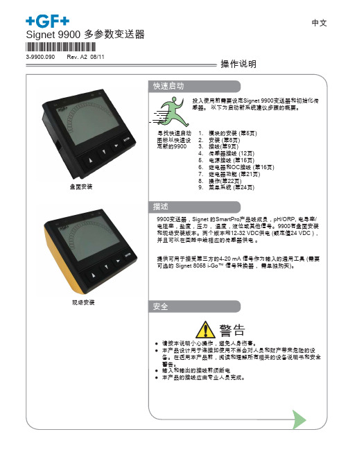
现场安装
安全
警告
● 请按本说明小心操作,避免人身伤害。 ● 本产品设计用于连接如使用不当会对人员和财产带来危险的设
备。在适用本产品前,阅读和理解所有相关的设备说明书和安全 警告。 ● 输入和输出的接线前须断电 ● 本产品的接线应由专业人员完成。
目录
Georg Fischer Signet 专业流体测量
描述
9900变送器,Signet 的SmartPro产品线成员,pH/ORP, 电导率/ 电阻率,盐度,压力, 温度,液位或其他信号。9900有盘面安装 和现场安装版本。两个版本均12-32 VDC供电 (额定值24 VDC ), 并且可以在回路中给相应的传感器供电 。
提供可用于接受第三方的4-20 mA 信号作为输入的通用工具 (需要 可选的 Signet 8058 i-Go™ 信号转换器, 需单独购买)。
可插拔模块 ................................................................................6 继电器模块 ................................................................................6 电导/电阻率模块 .......................................................................7 H COMM 模块 ..........................................................................7 安装 ................................................................................................8 接线 ................................................................................................9 信号类型:频率 ......................................................................10 信号类型:数字 (S3L) .............................................................10 信号类型:4-20mA .................................................................11 Terminal Identification ............................................................11 传感器接线 ..............................................................................12 电源接线 .................................................................................15 继电器和集电极开路输出接线 .................................................16 继电器和集电极开路输出 ........................................................17 继电器功能....................................................................................21 操作 ..............................................................................................22 菜单系统 .......................................................................................24 系统设定菜单 ..........................................................................24 常用菜单 .......................................................................................26 电流回路菜单 ..........................................................................26 继电器菜单 ..............................................................................27 选项菜单 .................................................................................29 传感器菜单....................................................................................30 流量 ........................................................................................30 pH ...........................................................................................32 ORP ........................................................................................34 电导/电阻率菜单 .....................................................................35 压力 ........................................................................................37 液位/体积量 .............................................................................38 温度 ........................................................................................40 4-20mA ...................................................................................41 盐度 ........................................................................................43 故障诊断 .......................................................................................45 附录 ..............................................................................................46 平均时间 .................................................................................46 算法模式电流回路输出 ............................................................47 自定义测量 ..............................................................................48 标定步骤- pH ..........................................................................52 标定步骤- ORP .......................................................................55 标定步骤-电导率/电阻率 .........................................................56 标定步骤-流量 .........................................................................57 标定错误信息 ..........................................................................58 USP(美国药典)限定 ................................................................59 规格 ..............................................................................................60 订货信息 .......................................................................................64
日锋9900说明书

R I F E N GRF9900变频调速器使用说明书哈尔滨市日锋电子有限责任公司序言感谢您选用哈尔滨市日锋电子有限责任公司的RF9900优化空间电压矢量PWM控制变频调速器。
本使用说明书为随机技术文件。
是您正确使用,安全运行的指导文件,请务必详细阅读和妥善保存。
为了充分发挥本产品的优越特性,确保使用者及设备的安全,在安装、调试、使用前,请认真阅读本使用说明书,详细了解变频器的安装,运行参数设定,安全注意事项,异常诊断及日常维护安全操作等事项。
请将此说明书交至实际使用者。
如在使用过程中,遇有疑难问题或特殊要求,请同本公司办事处或经销商联系,也可同本公司客户服务中心联系。
服务热线:800-8985852本使用说明书资料内容如有变更,恕不另行通知目录安全运行的注意事项 (5)1、验收 (6)1-1、检验 (6)2、安装 (7)2-1、选择安装变频器的环境 (7)2-2、安装空间选择 (8)2-3、安装尺寸 (9)3、接线 (10)3-1、外围设备和任选件的接线 (11)3-2、连接图 (12)3-3、主回路的接线 (13)3-4、接地 (17)3-5、控制电路的接线 (18)3-6、接线检查 (18)4、运行 (19)4-1、面板按键功能定义 (19)4-2、工作状态定义 (19)4-3、键盘使用 (19)4-4、变频器运行 (20)5、产品技术指标及规格 (22)6、功能参数表 (25)7、参数使用详细说明 (32)8、常见故障、异常现象及对策 (47)9、选件 (49)10、应用范例………………………………………..…………………….55. 附录附录1:定期维护及检查 (58)附录2:变频器适用上的注意 (60)附录3:电机适用上的注意............................ .. (62)附录4:周边设备适用上的注意......................... .. (64)安全运行的注意事项RF9900系列变频器 安装、运行、维护或检查之前要认真阅读本说明书。
网络电力仪表品种及选型方法
网络电力仪表 品种及选型方法上海安科瑞电气股份有限公司 1、概述网络电力仪表是针对电力系统、工矿企业、公共设施、智能大厦的电力监控需求而设计 的。
它能测量所有的常用电力参数,如三相电流、电压,有功、无功功率,电度、谐波等。
由于该电力仪表还具备完善的通信联网功能, 所以我们称之为网络电力仪表。
它非常适合于 实时电力监控系统。
该表具有很高的性能价格比, 可以直接取代常规电力变送器及测量仪表。
作为一种先进 的智能化、数字化的前端采集元件,该系列网络仪表已广泛应用于各种控制系统、SCADA 系 统和能源管理系统中。
2、国内主要品牌及型号国内生产网络电力仪表厂家、 型号品牌繁多, 主要常见的产品有: 雅达 YD2200、 YD2100、 YD2110、YD2050、YD2030、YD2020 智能电力检测控制仪表;溯高美 DIRIS A20、A40,DIRIS CMV2;上海二工 PD800H、PD800H-M13、PD800H-M14、PD800H-X13、PD800H-X14;保定华异 特 HYT-DN 多功能电测仪;珠海派诺 PMAC9900E 综合电力测控仪、PMAC720 多功能电力监控 仪、PMAC720D-H-V、PMAC720C-H-V、PMAC720C-HM-V、PMAC720C-H-AI-V、PMAC720D-H-AO-V、 PMAC9900E-NR-V、PMAC9900E-2R-V、PMAC9900E-2R-D-V;江阴科达 KDY-1M4S2、KDY-1M7S2、 KDY-1M9S2;华通测控 PDM-803HE、PDM-803HA、PDM-803H;上海安科瑞 ACR10E、ACR10EL、 ACR10EFL、ACR100E、ACR110E、ACR120E、ACR120EL、ACR120EFL、ACR200K、ACR200ILH、 ACR200ULH、ACR200UILH、ACR200E、ACR210E、ACR220E、ACR220EL、ACR220EFL、ACR300E、 ACR310E、ACR320E、ACR320EL、ACR320ELH、ACR320EFLH、ACR330ELH、ACR410E、ACR420E、 ACR430EGH、ACR450EGH,四象限电能,复费率电能,正负零序分量、电流 K 系数,电压波峰 系数, 电话波形因子, 事件记录, SOE 谐波分量; 斯菲尔 PD194Z-2SY、 PD194Z-9SY、 PD194Z-2S4、 PD194Z-9S4 、 PD194Z-9S9 、 PD194Z-9S9A 、 PD194Z-2S7 、 PD194Z-2S7A 、 PD194Z-2S4K 、 PD194Z-1S5、 PD194E-2S4、 PD194E-9S4、 PD194E-9S7、 PD194E-9S9、 PD194E-9F2、 PD194E-9F2A、 PD194E-9F3、PA2000-2、PA2000-3;珠海大唐 DTM600、DTM601、DTM602,配电综合测控仪; 亚特尔 MDM3000 综合电力测控仪 DNS/DNXS/DNS(X)9000 电能表;因泰莱 IDM30H、IDM30C、 IDM30HC; 爱博精电 ACUVIM-DX、 ACUVIM-EX、 ACUVIMII、 ACUVIM-400、 ACUVIM-AL、 ACUVIM-BL; 盛善 SD96-EZ1、 SD96-EZ2、 SD96-EZ3、 SD96-EY3、 SD42-EZ2、 SD42-EZ3、 SD42-EY3、 SD96-EG3、 SD42-ES1、SD42-EG1、SD96-EG1、SD96-ES3、SD42-ES3;深圳中电电力 PMC-530A、PMC-5330、 PMC-5350、 PMC-510A、 PM700MG、 PM700PMG、 PM710MG、 PM800、 PM810、 PM820、 PM850、 ION7550、ION7650、ION7300、ION7330、ION7350、ION6200;施耐德 PM810、PM820、PM850、PM870、 PM700、PM700P、PM710、PM200、PM200P、PM210 电力参数测量仪;高力特 GGE ET6000 电力 监控单元;苏州万龙 ST400M1、ST400M2、ST400M3、ST400M5、ST400H1、ST400H3、ST400H5、 ST400III1、ST400III2、ST400III5 智能型电力测控仪表;合肥友恒 YH2010A、YH2010B 多 功能网络电力仪表; 东瑞 PD204Z-2SY、 PD204Z-2S4、 PD204Z-2S4K、 PD204Z-2S4、 PD204Z -9S4、PD204Z-2S7、PD204Z-9S7、PD204Z-9S9;美国电气控制 QP650、QP550、QP450、 QP451、QP452、QP300、QP301、QP302;广州汉光 PD866E-718、PD866E-730、PD866E-518、 PD866E-545、PD866E-560,多功能电力仪表;合肥英特 YTWPI-3(4)、YTZJ-1、YTZJ-1A 智能 型电力监控仪;西安超龙 CHR801、CHR803、CHR804 电力测控仪;陕西和创 HD2000、HD2200、 HD2300 智能电力监控仪;北京易艾斯德(ESDTEK)EM600A、EM600B、EM600C、EM600D 智能 电量仪表,EM600E、EM600F、EM600G、EM600H、EM600I、EM600M、EM600N、EM600P,电力监 控装置 EM900A、EM900B、EM900C、EM900D、EM900E;上海宾瑞 BRN-D302-AS、BRN-D303-AS、 E203-AS、E202-AS;鑫龙自动化 DMX300B、DMX300C、DMX301、DMX302、DMX303、DMX306、 DMX308;上海华健 LCM-100、LCM-120、LCM-101、LCM-102、LCM-122、LCM-123、LCM-103、 LCM-124、LCM-105、LCM-500、LCM-501、LCM-503、LCM-504、LCM-505 智能监测装置;昆明 阳光 PM98E80、PM98E83M、PM98E83E、PM98E81E、PM98E81V 交流电参数测量表,PM98E83C、 PM98E83R 、 PM98E83R 、 PM98E83A ; 新 未 来 NFC-2000 配 电 智 能 监 控 终 端 ; 陕 西 科 飞 KFDJ-6350-II、KFDJ-6342-II、KFDJ-6351-I 智能电力监测仪等等。
计通电量仪MCP400说明书

注意:VOLTS MODE=3 WIRE WYE 只能在电压平衡的情况下提供精确的测量。如果 B 相电压不等 于 A 相和 C 相电压,则功率读数将达不到仪表的精度。
注意: 1、VOLT MODE = 3 WIRE WYE 2、注意每个 PT 和 CT 的极性。
2.5 三相星型(Y)系统连接
4 线和 3 线 Y 型系统接线图。MCP400 检测各相线对地的电压,如果监测是 100V-347V 系统,输 入可以直接连接。
MCP400 仪表上的 VOLTS MODE 应设置为:4 WIRE WYE。
注意: 1、VOLT MODE =4 WIRE WYE。 2、注意每个 CT 的极性。
如果系统电压超过 347/600V,必须采用 PT,PT 初级和次级必须接成星型(Y),超过 25W 则次级必须用保险丝。
VOLT MODE 应设置为:4 WIRE WYE
注意: 1、VOLT MODE = 4 WIRE WYE。 2、 注意每个 PT 和 CT 的极性。
2.6 三相△形(DELTA)系统的连接
当设置为不接地(浮地)△形接线,则需要 PT 及检测各相的线间(L-L)电压,电压模式应 设为 3 线△形:VOLTS MODE=3 WIRE DELTA
在开放式的△形方式中,MCP400 可以两种方式连接:使用 2 个或 3 个 CT。
注意: 1、VOLT MODE = 3 WIRE DETA 2、 注意每个 PT 和 CT 的极性
MCP400 标准电力监测仪 使用说明书
Installation & Operation Manual Version 2.0
PMAC9900产品说明书

界面友好 该功能在用户配置显示单元时有效 用户可 以方便的通过显示单元查询数据或者是进 行现场编程
运行方便 全部的测量值 整定值都可以通过本地或者 是通讯口存取
信息透明 全部的测量数据都采用一次侧数值显示
完善的数据查询功能
PMAC®9900 提供两种方式供用户查询实时 监测的数据量
显示 通过独立单元的显示模块 用户可以任意查 询所关心的数据 并且可以进行现场的编 程 调整仪表的工作参数
功率因数计算
PMAC®9900 可以计算出全相限的功角值 用户可以查询到当前功角的超前滞后关系 与功率数据一样 接线的对应关系以及 CT 同名端关系都会影响到功率因数的实际计 算值
频率测量
PMAC®9900 工作于不同系统模式时 频率 测量的采集通道时不相同的 在三角形模式 下 PMAC®9900 是通过 C 相电压通道测量 频率 其它模式下 PMAC®9900 是通过 A 向电压通道测量频率的
显示单元
三相四线星形 三相三线星形和 DEMO 模式
序
电压
相序
电流
号
1 A 相电压
A
A 相电流
2 B 相电压
B
B 相电流
3 C 相电压
C
C 相电流
4 平均相电压 LN 平均相电流
5 AB 线电压 AB A 相电流
6 BC 线电压 BC B 相电流
7 CA 线电压 CA C 相电流
8 平均线电压 LL 平均相电流
适用于电压等级超过 600V 线 系统 适用于三相三角形系统 此时仪表电压模式设置为 3 WYE 仪表 PT USE?为 YES 设置 PT PRIMARY 参 数和 PT SECONDARY 参数 Ixx 表示电流端子 Vx 表示电压端子
广州智光仪表20XF及35XE的使用说明
Guangzhou Zhiguang Electric Co. Ltd
IDIN 200F/201F-MS 三相电能监测仪 使用说明书
( 软件版本:1.0.0 )
广州智光电气股份有限公司
IDIN200F/201F 使用说明书
目录
1 产品介绍....................................................................................................................................................... 1 2 功能简介....................................................................................................................................................... 1 3 技术指标....................................................................................................................................................... 1 4 面板说明....................................................................................................................................................... 2 5 基本操作......................................................................................................................................................... 2 5.1 开机界面..................................................................................................................................................... 2 5.2 循环显示界面............................................................................................................................................. 3 5.3 主菜单界面................................................................................................................................................. 4 5.3.1 监测菜单[-1-] ......................................................................................................................................... 5 5.3.2 基本参数设置菜单[-2-] .......................................................................................................................... 9 5.3.3 通讯参数设置菜单[-3-]....................................................................................................................11 5.3.4 版本信息[-4-] ....................................................................................................................................... 12 5.3.5 出厂设置[-5-] ....................................................................................................................................... 12 6 安装环境与结构......................................................................................................................................... 14 6.1 电气环境................................................................................................................................................... 14 6.2 使用环境................................................................................................................................................... 14 6.3 安装尺寸................................................................................................................................................... 14 6.4 电气连接................................................................................................................................................... 14 6.4.1 CT、PT 的连接.................................................................................................................................... 16 6.4.2 遥信开入连接 ..................................................................................................................................... 16 6.4.3 通讯连接............................................................................................................................................. 16
西格尼特9900传感器说明书

English Signet 9900 Transmitter*3-9900.090*3-9900.090 Rev. D 12/13Operating Instructions Panel MountField MountGeneral Information•29900 TransmitterDimensions & Module Installation9900 TransmitterPlug-In Modules & Relay Module49900 TransmitterCond/Res & H COMM Modules59900 Transmitter69900 TransmitterBatch & Output Modules** N OTE:Verify 9900 Transmitter generation in the OPTIONS Menu.NOTE:T he 4 to 20 mA Output, Direct Conductivity, and Batch Modules share the same installation site on the 9900 base units.Only one of these modules can be used per 9900 Transmitter.Installation7 9900 TransmitterWiring89900 Transmitter99900 Transmitter Signal TypeFlow sensormodels withFrequency Output Maximum Cable Length 60 m (200 ft)305 m (1000 ft)515/8510X 525X2000X 2100X 2507X 2536/8512X 2537X 2540X 2551X 2552XIn case of noiseinterference, connect the cable shield to earth ground.Maximum total cable length of the Digital (S 3L) Bus:The quality of the cable used in the bus determines the maximum length of all branches combined.The maximum cable length may not exceed 305 m (1000 ft),regardless of current requirements.Signal Type109900 TransmitterTerminal Identifi cation11 9900 Transmitter129900 TransmitterSensor WiringTechnical Notes:• See corresponding product manuals for maximum cable length.• Maintain cable shield through cable splice.• Route sensor cable away from AC power lines.• 515/8510 and 525installations, connect the silver (shield) wire to earth ground in case of EMI noise interference.Technical Notes:• Wiring terminals on the 2537 are rated for 16 to 22 AWG wires.• The cable must be 7 mm to 10 mm in diameter (0.275 in. to 0.394 in.) to seal properly in the liquid-tight connector.• The conduit ports have ½-inch NPT threads. After routing the cables, seal the port with a liquid-tight conduit connector (3-9000.392-1) or with conduit.• The 2537 models can connect to the 9900 via a relay frequency signal or with a Digital (S 3L) output. Signet recommends installing the Digital (S 3L) output model (2537-5) because Digital (S 3L) is more accurate.• See 2537 instruction manual for additional installation information.Sensor Wiring 2551 Technical Notes:139900 Transmitter149900 TransmitterTechnical Notes:• The cable length from the 8058 to the 9900 must not exceed 60 m (200 ft).• When using the 8058-2, connect the loop source to Channel 1 input ONLY .• See the 8058 manual for more information.Sensor WiringWiring for:Signet 8058 i-Go™4-20 mA to S L ConverterO u t p u t S 3LDATA GND SHLD V+8058-1close-upBlackRed ShieldWhite 8058-19900 S 3L Inputs08058-27 8 9N/C S L DATA3close-up8058-2DATA GND V+SHLD BLACKWHITE RED 9900 S 3L InputsTechnical Notes:• Use three conductor shielded cable for sensor cable splices up to 305 m (1000 ft) max.• Maintain cable shield through cable splice.• Route sensor cable away from AC power lines.• Connect the silver (shield) wire to earth ground in case of EMI noise interference.Technical Notes:• The 2850 has no SHIELD wire.• To work correctly with the 9900, the 2850 must be set for the custom cell constant or the actual probe cellconstant and the 9900 set for a 1.0 cell constant.* 2551-XX-21, -41Display Magmeter2250235024502551*27502850Black Red ShieldWhite V+DATA GND SHLD 9900 S 3L InputsWiring for:NOTE: The 2850 has no SHIELD wire.159900 Transmitter Technical Notes:• 3-2610-31 Dissolved Oxygen Sensor can be connected to the 9900 only via a 3-8058-1 or 3-8058-2 i-Go Signal Converter.• Program the 9900 for the 2610 DO sensor via the 4 to 20 mA sensor settings on the 9900 (see page 42).• See the 2610 manual for more information.Sensor WiringTechnical Notes:• When using the 8058-2 with the 9900, connect the loop power supply to 8058-2 Loop 1 inputs ONLY as shown in the fi gure.• See the 8058 manual for more information.Technical Notes:• The cable length from the 8058 to the 9900 must not exceed 60 m (200 ft).Technical Notes:The wiring of the 3-2610-41 is non-standard:• RED is 12 to 24 VDC • WHITE is Data• BLACK is VDC Ground• A jumper MUST be installed between PWR- and S 3L GND.Sensor Wiring• All of the electrical169900 TransmitterRelay Wiring179900 TransmitterRelay Wiring189900 TransmitterRelay Functions199900 Transmitter209900 TransmitterHigh Setpoint:Relay is on when the measured value is higher than the setpoint.Open Collector Output●Longer life than a mechanical relay ●No moving parts●Faster ON/OFF switching capabilities than mechanical relays ●Can switch DC voltage only (< 30 VDC)●Not recommended for use with inductive loads.Relay OutputsCycle High/Low:The relay can stay energized for a set length of time after the process value goes above (or below) the setpoint.The relay will stay on for the CYCLE TIME and then turn off, even if the process value is still above (or below) the setpoint. The cycle will not repeat until the process value goes below (or above) the setpoint minus the hysteresis after the relay times out.In FLOW, Cycle High activates the relay each time the volume reaches the SET VOLUME setpoint (see page 28).NOTE: To reset the timer (or volume in Flow): in the RELAY menu, select TEST RELAY function. The timer will reset to 0 if the condition no longer exists when the TEST is performed. The timer will restart if the condition still exists.Low Setpoint:Relay is on when the measured value is less than the setpoint.Relay Outputs• Volumetric PulseA pulse is generated each time a speci fi ed volume of fl uid is registered. For fl ow inputs only.NOTE: Relay LEDs are not lit in VOLUMETRIC PULSE mode.• Totalizer VolumeRelay activates and latches when a speci fi ed volume of fl uid is registered. For Flow inputs only.Total Volume mode counts the TOTALIZER Units until the setpoint volume is reached, then turns on the relay until the resettable totalizer is reset.If the Resettable Totalizer reading is greater than the setpoint, the relay will be turned on immediately. The relay will be off when the totalizer is reset to zero.This mode is useful to trigger a reminder when a process is due, as for a backwash cycle or fi lter change.• Pulse Width ModulationPWM automatically varies the ratio of ON time to OFF time proportional to minimum and maximum range settings.The relay period is the sum of the time a relay is ON and the time it is OFF.Relay pulse width is the time the relay is ON.The 9900 must be programmed with the relay period, and with the low and high setpoints.NOTE: The PWM mode is not used for Pressure applications.NOTE: Relay LEDs are not lit in PWM mode.Relay OutputsExample:• The pulse width will be 0% of the relay period (relay always OFF) when the process value is less than the minimum range.• The pulse width will be 100% of the relay period (relay always ON) when the process value is greater than the maximum range.• The pulse width will be 60% of the relay period when the process value is at 60% of the span between the minimum and maximum range.OperationOperationKeypad FunctionsThe four buttons of the keypad are used to navigate display modes according to the descriptions in this table. Notice that the function of each button may change depending on the display mode.3sEditInput EditSaves ChangesInput Edit Choices(Password may be required)or ororSelect another Menu ItemReturn to View Mode+2x+OrThis basic operating procedure repeats throughout the 9900 program:1. Press ENTER for 3 seconds to enter MENU mode.2. Press ► to move to the desired menu then press ENTER to select it. (Password may be required.)3. Press ▲ or ▼ to select the desired menu item for editing.4. Press ► to edit the value/selection.5. Press ENTER to store the new value/selection.6. Press ▲ or ▼ to select another menu item if desired. Repeat steps 3-5 as required.7. Press ▲+▼ to select a different menu to edit. Repeat steps 2-5 as required.8. When fi nished editing all menus, press ▲+▼ again to return to normal operation.The menu is constructed in a loop, so you can move forward and backward to select an item. After any item is saved (by pressing ENTER), the display will return to the previous menu.System Setup: Menu NavigationOperationMENU Mode OverviewThe MENU mode enables the user to view and con fi gure all menu items. The fi ve menus available are: CAL , INPUT , LOOP , RELAY , and OPTION .MENU Mode is entered by pressing and holding ENTER for three seconds.The ► button is used to change the position of the blinking cursor. When the desired menu is blinking, press ENTER.In the selected menu, use the ▲ and ▼ keys to navigate through the menu.Use the ▲, ▼ and ► keys to edit the selected item (see Menu Navigation discussion, pg. 24).To save the new selection, press the ENTER key. A message displaying “Saving…” will be displayed for 3 seconds. After this message is displayed, the newly selected value will be displayed, if applicable.VIEW Mode OverviewThe top level of menus is referred to as the VIEW Mode . This view displays measurement values as well as current outputs and relay status. The radial bar graph represents the measurement value that is also displayed in the 7-segment numeric fi eld below the bar graph. The bar graph is primarily used to display the full scale range of the sensor, but can be scaled via a menu item.During normal operation, the 9900 displays the VIEW mode. ●To select a display, press the ▲ or ▼ arrow keys. The display selections scroll in a continuous loop.●Changing the display selection does not interrupt system operations. ●No password is necessary to change display selection. ●Output settings cannot be edited from the View Mode.●The display will return to the VIEW mode if no button is pressed for 10 minutes.Password OverviewThe password is often required to start editing. Once entered correctly, this password will not be needed for subsequent edits. However, once the menu system is exited, the password will again be required when edit mode is re-entered.Your choice of password (STD or CODE) is selected in the Options Mode.●STDThe standard (STD) password is ▲▲▲▼, pressed in sequence. This password is designed to protect the 9900 from unintentional changes. It is best suited for systems where a group of people need to be able to change settings. ●CODEThe CODE default setting is 0000, adjustable to any 4-digit numerical code up to 9999. Using a personal code provides the maximum degree of security. This code can be modi fi ed in the Options mode.Menu SystemMenu System INPUT MenuMenu SystemMenu SystemMenu SystemFlowFlowpHpHORP This is the normal displayand does not time out.Conductivity/ResistivityConductivity/ResistivityPressureLevel / Volume This is the normal displayand does not time out.Level / VolumeTemperature This is the normal displayand does not time out.4 to 20 mA4 to 20 mASalinitySalinityDissolved OxygenDissolved OxygenTroubleshootingAppendix With SENSITIVITY still set to zero and AVERAGING set to MED or HIGH the rate is stabilized, but a sharp change in rateDe fi ning a Custom Tank1. Determine where the level measurement shouldstart. This is the zero reference point (Z). Review the diagram to help select the best option.2. Determine where you will mount the sensor. Thisis S LOC . Consult the Sensor manual for information regarding the best location for the sensor.3. Measure the distance between Z and S LOC .This is O(ffset).4. Enter the Offset into the INPUT Mode menu.Zero reference point (Z):The point in the vessel where you want the 9900 to display zero (0 ft, 0 gal. etc.).• If Z is located below the fl uid surface, the 9900 will display a positive level measurement.• If Z is located above the fl uid surface, the 9900 will display a negative level measurement.Sensor Location point (S LOC ):The point on the level sensor where the measurement is taken.• The pressure sensor measures from the centerline of the diaphragm.Offset (O):The distance from Z to S LOC .• Enter a positive value in the Calibrate menu if the sensor is located above Z.• Enter a negative value in the Calibrate menu if the sensor is located below Z.• Enter 0 in the Calibrate menu if the sensor is located at Z.Level (L):The distance from Z to surface of fl uid (displayed as “Level” by 9900).Appendix。
- 1、下载文档前请自行甄别文档内容的完整性,平台不提供额外的编辑、内容补充、找答案等附加服务。
- 2、"仅部分预览"的文档,不可在线预览部分如存在完整性等问题,可反馈申请退款(可完整预览的文档不适用该条件!)。
- 3、如文档侵犯您的权益,请联系客服反馈,我们会尽快为您处理(人工客服工作时间:9:00-18:30)。
始就开始累加 直至计满翻转 重新累加
注意 用户可以通过显示单元 就可以在本地进行 电度清零 或者是通过通讯口在远地进行电 度清零
功率计算
PMAC®9900E 可以通过测量电压 电流信 号计算出三相的有关功率参数 除视在功率 以外 有功功率和无功功率是有符号标志 的
注意 用户在接线时 应当注意电压 电流的相序 对应关系 否则会造成功率计算数据错误 而且 应当注意 CT 的同名端接线关系 否 则会造成功率计算数据为负值
96mm 安装深度不超过 100mm 装置功耗不超过 5W
界面友好 该功能在用户配置显示单元时有效 用户可 以方便的通过显示单元查询数据或者是进 行现场编程
运行方便 全部的测量值 整定值都可以通过本地或者 是通讯口存取
信息透明 全部的测量数据都采用一次侧数值显示
稳定可靠 采用了多种抗干扰和保护措施 保证设备长 期工作的稳定性 可靠性
9
操作
说明
PMAC®9900E 可以通过显示模块查询测量 数据或者是进行现场编程 以下具体说明操 作方法 如果用户没有要求配置显示模块 该章节内容可以跳过 PMAC®9900E 具有 多种配置 以下章节所叙及的内容都以 PMAC®9900E-2R 操作为参考
PILOT® ELECTRONIC
PMAC®9900E 标准电量测控仪 说明书
Installation & Operation Manual
简介 目录
简介说明
2
测量
4
节点监视
6
控制
7
接线图
8
操作
10
通讯
18
外形尺寸
19
技术参数
21
PMAC®9900E 标准电量测控仪
2
说明
பைடு நூலகம்
PMAC®9900E 标准电量测控仪是一种简单 可靠的测控装置 可以广泛应用于电力系 统 环境监控 低压配电等自动化领域
三相四线系统 2 个 PT 3 个 CT
适用于电压等级超过 347V(相)/600V 线 系统
适用于 B 相接地系统 此时仪表电压模式设置为 3 WYE Y 仪表 PT USE?为 YES 设置 PT PRIMARY 参 数和 PT SECONDARY 参数 Ixx 表示电流端子 Vx 表示电压端子 选用改进型的 PMAC®9900E
模块化设计结构
PMAC®9900E 采用结构化的设计模式 方 便未来技术的升级更新 提供用户更多的选 择
独立的主机模块 独立的显示单元 可选择的通讯单元 可选择的模拟输入单元 可选择的节点监测功能 可选择的继电器输出功能
简单实用
PMAC®9900E 采用了许多简化实用的设 计 安装
根据用户指定数据进行设备整定 设备采用正面安装模式 开孔尺寸 96mm x
PMAC®9900E 标准电量测控仪
3
测量
说明
PMAC®9900E 按操作要求来显示测量值 显示一次回路的电量参数为 电压
测量相电压 Va Vb 和 Vc 以及平均值 测量或计算线电压 Uab Ubc 和 Uca 以及 平均值
电流 测量电流 Ia Ib 和 Ic 以及平均值
有功功率 计算三相有功功率 Pa Pb Pc 以及总和
完善的数据查询功能
PMAC®990E0 提供两种方式供用户查询实 时监测的数据量
显示 通过独立单元的显示模块 用户可以任意查 询所关心的数据 并且可以进行现场的编 程 调整仪表的工作参数
通讯 采用 RS485 通讯接口 方便用户进行网络通 讯 与 MODBUS-RTU 标准完全兼容 并且提
供开放式的协议标准 方便第三方进行开发
当系统电压等级超过 347V 相 /600V 线 时 PMAC®9900E 电压测量回路必须通过 PT 才可以接入系统中 通常情况下 用户 可以选择次级额定输出为 100V 的 PT
由于 PT 的引入 会直接影响仪表测量的精 度 所以用户在选择 PT 时请注意其线性度 和精度等级
频率 测量并计算三相频率
外部无源节点
当外部状态信号仅仅提供一个位置信息时 则需要 PMAC®9900E 内部输出节点闭合时 的反馈电压信号 通常采用右图的接线方 式
外部有源节点
当外部状态信号不仅仅提供位置信息 额外 还提供反馈电压信号 此时 PMAC®9900E 就不能采用内部电源输出 而必须调整其内 部配置 并对接线做出相应改动 接线示意 图如右所示 如果现场采用的是有源节点 用户在订货时 应当及时通知我们外部电源的电压等级 以 方便我们进行适当的硬件配置 否则会造成 不应有的器件损坏
电度
PMAC®9900E 可以统计相关的功率电度参 数 根据功率的方向性 可以分别计算输入 电度 输出电度以及净值 PMAC®9900E 电度时采用累加的方式计 算 除非用户强制清零 否则自初次上电开
PMAC®9900E 标准电量测控仪
5
节点监视
PMAC®9900E 配置了四路节点输入端口 用作监测外部的状态信号 根据外部节点的 不同电压状态 可以以下两种接线模式
PMAC®9900E 标准电量测控仪
4
测量
维护时 都必须采用适当的预防措施 例如 短接 CT
PMAC®9900E 额定的最大测量量程为 32 000A
PMAC®9900E 测量电流的过载能力一般为 额定测量电流的 1.4 倍 用户在进行设计时 应当注意这点 防止内部测量回路出现饱 和 造成测量不准确
方便的节点状态监测
PMAC®9900E 提供灵活的可配置的四路节 点输入 适用于监测断路器位置信号 刀闸 位置信号等状态信息 在低压配电网络中 基本可以实现一回线路状态量监测的需求 节点输入电压可选择 即可选用仪表内部开 出的低压电源 也可以适用外部高压电源的 输入要求
可编程的输出继电器
PMAC®9900E 可以提供多路继电器输出信 号 支 持 最 高 可 达 250Vac/10A 或 30Vdc/10A 的节点容量 继电器输出脉冲可整定 动作时间可整定 既可以用作现场自动监测电量 也可以进行 远方遥控操作
PMAC®9900E 标准电量测控仪
8
接线图
三相三线系统 2 个 PT 3 个 CT
适用于电压等级超过 600V 线 系统 适用于三相三角形系统 此时仪表电压模式设置为 3 WYE 仪表 PT USE?为 YES 设置 PT PRIMARY 参 数和 PT SECONDARY 参数 Ixx 表示电流端子 Vx 表示电压端子
功率因数计算
PMAC®9900E 可以计算出全相限的功角 值 用户可以查询到当前功角的超前滞后关 系 与功率数据一样 接线的对应关系以及 CT 同名端关系都会影响到功率因数的实际 计算值
频率测量
PMAC®9900E 工作于不同系统模式时 频 率测量的采集通道时不相同的 在三角形模 式下 PMAC®9900E 是通过 C 相电压通道 测量频率 其它模式下 PMAC®9900E 是 通过 A 向电压通道测量频率的
无功功率 计算三相无功功率 Qa Qb Qc 以及总和
功率因数 计算三相功率因数 PFa PFb PFc 以及三
相总值
视在功率 计算三相视在功率 Sa Sb Sc 以及总和
电压测量
当系统电压等级小于 347V 相 /600V 线 时 PMAC®9900E 电压测量回路可以直接 接入系统
注意 PMAC®9900E 标准型号是可以满足大部分 现场需求的 但在某些特殊场合下 例如在 一些发电厂中会采用 B 相接地系统 还有部 分现场会采用三相五线系统 这样就要求仪 表的中性点和地相分离 所以 PMAC®9900 提供了一种改进型号以满足这些现场的需 求 用户在设计时请注意选择适当的规格型 号
适用于电压等级不超过 347V(相)/600V 线 系统 适用于采用中性线的三相星形系统 仪表电压模式设置为 4 WYE Y 仪表 PT USE?为 NO Ixx 表示电流端子 Vx 表示电压端子
三相四线系统 3 个 PT 3 个 CT
适用于电压等级超过 347V(相)/600V 线 系统
适用于采用中性线的三相星形系统 此时仪表电压模式设置为 4 WYE Y 仪表 PT USE?为 YES 设置 PT PRIMARY 参 数和 PT SECONDARY 参数 Ixx 表示电流端子 Vx 表示电压端子
其它 可以接受用户定制需要计算的电参量 有
关具体细节内容请与公司联系
电流测量
通常情况下 PMAC®9900E 都必须采用 CT 才可以进行电流测量 CT 的次级额定输出 需要符合 PMAC®9900E 的额定电流输入要 求 一般情况下 有 1A 和 5A 两种
注意 当系统采用 CT 后 有关的 CT 回路是严格 禁止开路的 否则会因为初级的励磁作用在 次级产生非常高的电压 造成人员伤亡或者 设备的损坏 用户在对 CT 回路进行安装和
时间计时器
PMAC®9900E 内部具有两类时间计数器控 制继电器的状态 一类为延时动作时间计时 器 另一类为延时返回时间计时器 通过这 两类计时器的配合 可以自由控制继电器的 输出方式 延时动作时间计时器用以控制继电器动作 需要延迟的时间 当继电器监测参量超出限 值范围时 该计时器开始计时 在用户设定 的时间内如果参量一直超出限值 则计时器 计时完毕后就会触发继电器闭合 如果在设 定时间内 参量返回限值以内 则继电器不 会闭合 延时返回时间计时器用以控制继电器闭合 后自动复归的时间 当继电器闭合后 该计 时器就会开始计时 满足用户设定的时间 后 继电器会自动断开 通过该计时器的设 定 可以将继电器控制为脉冲输出的方式
三相三线系统 2 个 PT 2 个 CT
适用于电压等级超过 600V 线 系统 适用于三相三角形系统 此时仪表电压模式设置为 3 WYE 仪表 PT USE?为 YES 设置 PT PRIMARY 参 数和 PT SECONDARY 参数 Ixx 表示电流端子 Vx 表示电压端子
