IRI2010热成像仪中文用户手册
Fluke Ti25和Ti10热像仪说明书

Technical DataThe ultimate tools for troubleshooting and maintenanceFluke Ti25 and Ti10 Thermal ImagersThe perfect tools to add to your problem solving arsenal. Built for tough work environments, these high-performance, fully radiometric imagers are ideal for troubleshooting electrical installations, electro-mechanical equipment, process equipment, HVAC/R equipment and others.• All Fluke imagers come with enhanced prob-lem detection and analysis capabilities with IR-Fusion ® Technology. Simply scroll through the different viewing modes quickly to better identify trouble areas in Full IR thermal, picture-in-picture, or automatic blend visual and thermal images.• Optimized for field use in harsh work environments.• Engineered and tested to withstand a 2 m (6.5 ft)drop—When was the last time you dropped a tool?• Withstands dust and water—tested to an IP54 rating. • Delivers the clear, crisp images needed to findproblems fast.• Identify even small temperature differences that couldindicate problems with excellent thermal sensitivity (NETD).• Intuitive, three-button menu is easy to use—simply navigate with the push of a thumb.• No need to carry pen and paper—record findings byspeaking into the camera. Voice annotations can be recorded with every image you take. Voicecomments are saved along with individual images for future reference (Ti25 only).• Everything needed to get started is included.• Adjustable hand strap for left-or right-handed use.•Manufactured in the U.S.A.Detailed specifications Detailed SpecificationsTemperature Operating: -10 °C to 50 °C (14 °F to 122 °F)Storage: -20 °C to +50 °C (-4 °F to 122 °F) without batteries Relative humidity 10 % to 90 % non-condensingDisplay9.1 cm (3.6 in) diagonal landscape color VGA (640 x 480) LCD with backlight (selectable bright or auto)Controls and adjustmentsUser selectable temperature scale (°C/°F)Language selection Time/Date setEmissivity selection (Ti25 only)User selectable Hot Spot and Cold Spot on the image (Ti25 only)Ti25 allows user to adjust palette, alpha blend, level, span, PIP, and emissivity on a captured image before it is stored.Software SmartView ™ full analysis and reporting software includedPowerBattery: Internal rechargeable battery pack (included)Battery life: Three to four hours continuous use (assumes 50 % brightness of LCD)Battery charge time using ac adapter/charger and dc car charger: Two hours for full charge AC operation/charging AC adapter/charger (110 Vac to 220 Vac, 50 Hz to 60 Hz). Charges battery while imager is operating. Universal ac mains adapters included.Power saving Sleep mode activated after 5 minutes of inactivity, automatic power off after 20 minutes of inactivity Safety standards CE Directive: IEC/EN 61010-1 2nd Edition Pollution Degree 2Electromagnetic compatibility EMC directive: EN61326-1C-Tick: IEC/EN 61326US FCC: CFR 47, Part 15 Class A Vibration 2 G, IEC 68-2-29Shock25 G, IEC 68-2-29 (1 m drop, 5 sides)Dimensions (HxWxL)0.27 m x 0.13 m x 0.15 m (10.5 in x 5 in x 6 in)Weight 1.2 kg (2.65 lb)IP rating IP54Warranty Two-yearsCalibration cycle Two-years (assumes normal operation and normal aging)Supported languagesEnglish, Italian, German, Spanish, French, Russian, Portuguese, Swedish, Turkish, Czech, Polish, Finnish, Simplified Chinese, Traditional Chinese, Korean, and JapaneseGeneral specifications3 Fluke Corporation Ti25 and Ti10 Thermal ImagersFluke. Keeping your world up and running.®FLUKE-Ti25Thermal ImagerFLUKE-Ti10Thermal ImagerIncluded with productThermal imaging camera w/ 20 mm lens, ac power supply/battery charger (including mains adapters), SD memory card, SD card reader (USB) for downloading images into your computer, SmartView ™ software with free software upgrades for life, rugged hard, carrying case, soft transport bag, hand strap, users manual, warranty registration cardOptional accessoriesFluke-TI ChargerThermal Imager Car Charger(standard 12 V dc auxiliary power adapter) Compatible with both Ti25 and Ti10 models.Industrial Supply Syndicate54, Ezra Street, Kolkata - 700 001, INDIA Phone: 22350923, 22356676Email:************************Website: Fax: 033 30222923。
FLIR ONE Pro热成像仪产品介绍说明书
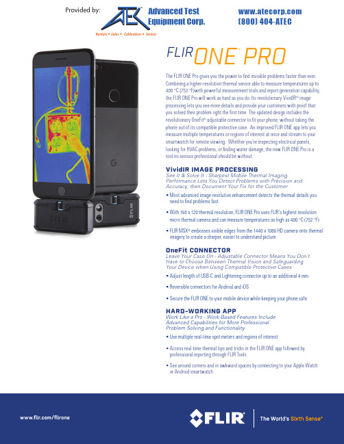
The FLIR ONE Pro gives you the power to find invisible problems faster than ever. Combining a higher-resolution thermal sensor able to measure temperatures up to 400 °C (752 °F)with powerful measurement tools and report generation capability, the FLIR ONE Pro will work as hard as you do. Its revolutionary VividIR ™ image processing lets you see more details and provide your customers with proof that you solved their problem right the first time. The updated design includes the revolutionary OneFit ™ adjustable connector to fit your phone, without taking the phone out of its compatible protective case. An improved FLIR ONE app lets you measure multiple temperatures or regions of interest at once and stream to your smartwatch for remote viewing. Whether you’re inspecting electrical panels, looking for HVAC problems, or finding water damage, the new FLIR ONE Pro is a tool no serious professional should be without.VividIR IMAGE PROCESSING See It & Solve It - Sharpest Mobile Thermal Imaging Performance Lets You Detect Problems with Precision and Accuracy, then Document Your Fix for the Customer• Most advanced image resolution enhancement detects the thermal details you need to find problems fast• With 160 x 120 thermal resolution, FLIR ONE Pro uses FLIR’s highest resolution micro thermal camera and can measure temperatures as high as 400 °C (752 °F)• FLIR MSX ® embosses visible edges from the 1440 x 1080 HD camera onto thermal imagery to create a sharper, easier to understand pictureOneFit CONNECTOR Leave Your Case On - Adjustable Connector Means You Don’t Have to Choose Between Thermal Vision and Safeguarding Your Device when Using Compatible Protective Cases • Adjust length of USB-C and Lightening connector up to an additional 4 mm • Reversible connectors for Android and iOS• Secure the FLIR ONE to your mobile device while keeping your phone safe HARD-WORKING APP Work Like a Pro - Work-Based Features IncludeAdvanced Capabilities for More ProfessionalProblem Solving and Functionality• Use multiple real-time spot meters and regions of interest• Access real-time thermal tips and tricks in the FLIR ONE app followed by professional reporting through FLIR Tools• See around corners and in awkward spaces by connecting to your Apple Watch or Android smartwatchFLIR ONE PRO ®Provided by: (800)404-ATECAdvanced Test Equipment Corp .®Rentals • Sales • Calibration • ServiceSpecificationsEquipment described herein is subject to US export regulations and may require a license prior to export. Diversion contrary to US law is prohibited. Imagery for illustration purposes only. Specifications are subject to change without notice. ©2017 FLIR Systems, Inc. All rights reserved. 06/06/1717-1746-OEM-FLIROne_Pro CORPORATE HEADQUARTERS FLIR Systems, Inc.27700 SW Parkway Ave.Wilsonville, OR 97070PH: +1 877.773.3547SANTA BARBARA FLIR Systems, Inc.6769 Hollister Ave.Goleta, CA 93117PH: +1 805.690.6600CHINA FLIR Systems Co., Ltd Room 502, West Wing, Hanwei Building No. 7 Guanghua Ave.Chaoyang District, Beijing 100004, China Phone: +86 10-59797755EUROPE FLIR Systems, Inc.Luxemburgstraat 22321 Meer Belgium PH: +32 (0) 3665 NASDAQ: FLIR。
热成像仪说明书 (Simpl. Chinese)
6
热像仪部件 ........................................................................................9
6.1 右视图 .................................................................................... 9
6.1.1 图 ............................................................................... 9
6.1.2 说明 ............................................................................ 9
9.2 说明 ..................................................................................... 16
#T559845; r. AD/ 9770/9770; zh-CN
7.2 说明 ..................................................................................... 14
8
在菜单系统中定位 ............................................................................. 15
6.3.1 图 ............................................................................. 11
酷睿红外体温测量热成像摄像头用户手册说明书

Infrared Body Temperature Screening Thermal CameraUser Manual2020-03Thank you for purchasing our Infrared Body Temperature Screening Thermal Camera. Please read this manual carefully before using. This camera’s technical specifications, operational methods and precautions are all included in this manual.If you need any other information not included in this manual, please feel free to contact us.The company reserves the right to modify this manual without prior notification.Dangers1.Please read this manual carefully before installation.2. Please note the warning notices on the camera and in this manual.3. Please apply exactly the power supply and voltage listed in this manual.4. For safety and camera’s proper functioning, please don’t power on the camera while connecting cables.5. Please ensure the intactness of the power line in case of injury and damage.6. Please install anti-lighting device in case of thunderstruck.7. Please mount this camera on a secure platform or bracket in case of injury.8. Unauthorized dismantling of this camera may incur injury or damage, so please contact us directly for any malfunction matters.9. In order to protect the lens from being stained or scratched, please don’t touch it.Caution1.For ensuring camera’s proper functioning, please don’t cover camera front.2. Protect the camera from direct sunlight to ensure the detector not being damaged.3. In case of water leakage, please don’t use organic solvent to clean camera’s housing.4. Please wait for another 30s before restarting camera.5.For camera with preset function, please pay special attention:It should avoid to patrol for long time, especially when the stay time is short for each preset. The motor of zooming & focusing lens is easy broken parts and can be easily damaged if patrolling for long time. If it is really necessary to use the patrol function, we strongly recommended NOT to use the preset function or extend the stay time for each preset. Please kindly contact us if you would like to know more info.6.The temperature measurement needs to be performed after the thermal imager is powered for 30 minutes to run stably.CATALOGChapter 1 Camera Introduction (5)1. Overview (5)2. Appearance (6)3. Dimension(mm) (7)4. Connector (9)Chapter 2 Operation (10)1. Installation and cable connection (10)2. Recommended installation environment (12)3. Common Faults (14)Chapter 3 Camera debugging instructions (16)Chapter 4 Instructions for software (26)Chapter 5 Warranty and After sales (32)Chapter 1 Camera Introduction1. OverviewInfrared Body Temperature Screening Thermal Camera, It is a non-contact, large-area, accurate, and efficient temperature measurement and screening device specially designed for dense crowds in public places. Based on the accurate temperature measurement technology of thermal imaging, people with abnormal body temperature can be detected and alarmed in time to assist the supervision department to implement rapid intervention methods. And emergency measures to prevent the spread of the virus epidemic in public places from the danger of spreading infected people in a wide range. It can be widely used in airports, railway stations, passenger stations, subway stations and other comprehensive transportation hubs, as well as in crowded areas such as schools and comprehensive parks.The entire system includes a front-end human body temperature measuring camera and temperature management software. Customers can configure and control computers by themselves. The management computer is equipped with temperature management software for managing temperature measurement equipment and temperature alarms.2. AppearanceVisible lensThermal cameraChart 1-1 Front and side viewCable connectionChart 1-2 Lateral and side view3. Dimension (mm)Chart 1-4 Front viewChart1-3 Connecting cables and power adaptersAir plug connector Cable interfaceDC12V connectorChart 1-5 Lateral viewChart 1-6 Mounting holes at the bottom of the camera4. ConnectorCamera output line definitions:Pin No. 1 2 3 4 5 6Pin definition 12V+RedGNDBlackOrangewhite TX+(RJ45-1)OrangeTX-(RJ5-2)Greenwhite RX+(RJ45-3)GreenRX-(RJ45-6)Pin No.7 8 9 10 11 12Pin definition Blue Blue white BrownwhiteBrown NC NCChapter 2 Operation1. Installation and cable connection(1) Installation There are mounting holes on the bottom of the camera, as shown in Figure 1-6. Ordinary photography tripod can be used for quick installation. The installation scheme is shown in the figure below.Quick-install panel:Mounting holes at the bottom of the camera:Remove the panel immediately by pulling the lever slightly backwards. After placing the panel, press it down tosnap the base.Chart 2-1 Tripod quick setup drawing(2)Aviation Plug InstallationChart 2-2 Aviation Plug Hole Chart 2-3 Aviation plug Pin When installing, please insert the head hole into the socket, make sure that the pin is inserted into the socket, then twist the upper fixed ring upward and to the right, and then complete the docking after hearing "Click" . When removing the plug, please twist the plug to the left, the plug will be removed, with the pin plug separation.Remove the panel and install itinto the mounting hole on thebottom of the temperaturemeasuring camera indicated bythe icon above.Chart 2-4 Aviation Plug Finished Installation(3) Cable connectionChart 2-5 connection diagram2. Recommended installation environmentThe temperature measurement principle of the infrared camera is measured by collecting infrared radiation radiated from the surface of the body of the person. The environmental conditions related to infrared transmission will affect the temperature measurement accuracy, especially air flow, air transmission rate, environmental humidity, and environment Temperature and other factors, it is strongly recommended that the camera be installed in an indoor environment. And to choose the appropriate Infrared Body Temperature Screening Thermal CameraCameraconnectionPower supplyNetworkcableComputerAviation plug retaining ringinstallation height and temperature measurement distance, the following diagram shows the installation environment recommendations.Erection height 1.8-2m5m3m2mPeople passing areaChart 2-6 Camera installation recommendationsThe erection height is about 1.8-2 meters, the working distance is generally 2-5 meters, and the best temperature measurement distance is about 2-3 meters.Chart 2-7 Camera installation and display3. Common FaultsThe table below includes the common faults during operation. Whenever these problems occur, you may refer to this table or contact us directly for proper solution.Fault Possible Cause SolutionNo image on Power damage or under Replace the original power.camera after poweronpowerWrong connection ofpower line ReconnectCircuit malfunction Check circuitThe network is notconnectedCheck the network connectioncables to ensure that the wiring iscorrect and in good contact Firewall blocks videotransmissionTurn off the firewall on the clientcomputerUnclear image Lens covered by objects Check if there is any cover Dirty lens Clear lensChapter 3 Blackbody use and installation instructions 1.Product appearanceNote: Please refer to the real object for the appearance of the blackbody. This picture is for reference only.2.Instructions(1)Connect the power supply, the power supply is AC220V.(2)Press the power switch, the indicator light is on to indicate that the power is on.(3)The factory default is 35 ° C, and the temperature will automatically rise to 35 ° C when the machine is turned on. If other temperature points are set during use, it will automatically rise to the temperature set last time when it is turned on next time.(4)Temperature setting:In this interface, , press◀. ▲. ▼ key to adjust the value in the (SV) window, set the required temperature, and after the adjustment, wait for the number to no longer change, and the temperature can be used for measurement after 30 minutes.(5)The blackbody furnace has been tested in operation when it leaves the factory. All parameters of the intelligent temperature controller have been optimized. It is forbidden to modify the parameters by yourself when not necessary.(6)After use, cut off the power.3.Precautions for using blackbodyBefore use, please check if there is enough space around you. The bottom and back of the device is a heat dissipation area. When using it, pay attention to cleaning up foreign objects that are easily sucked in to prevent damage to the device!The black body furnace can be used in a laboratory, a measurement room or a production site, and it should be placed horizontally on a table during use. When setting the instrument to be calibrated, it shall be kept at a specified distance from the bullseye of the black body furnace. At the same time, the instrument calibration system and the black body radiation surface must be on the same axis.In order to ensure the accuracy of temperature measurement, please place the surface temperature calibrator in a stable temperature environment. The ideal environment temperature is 10 ℃~25 ℃.The inspection must start from the low temperature point and then to the high temperature point. In order to prevent the rapid changes in temperature from damaging the components in the furnace, when the temperature rises from low temperature to high temperature or decreases from high temperature, it is necessary tostop the test and wait for the temperature in the furnace to approach room temperature before starting the test.Before installing or moving the instrument, turn off the power to avoid accidents such as electric shock.When used in the field, the power plug must be reliably grounded!Do not disassemble the components yourself. If there is any problem, please contact our company for repair.4. Installation instructions ● Blackbody installation●Installation height of thermal imaging temperature measuring camera: 2 meters; installation height of black body: 1.8 meters. The product installation isshown as follows:Mounting holes at the bottom of the blackbodyRemove the panel andinstall it into themounting hole at thebottom of the black body(choose one), and theninstall the black body as awhole back onto thetripod.The distance between the thermal imagingand the blackbody is 3 meters.Camera height 2m Blackbody height 1.8mThermal camera tripod installation diagramThe thermal imaging camera and the black body are installed on the same side, the pedestrian path is on the other side, and the distance between the camera and the black body is 3 meters, to avoid obstruction between the camera and the black body during temperature measurement.Blackbody installation diagramThe radiating surface of the black body must be facing the camera's irradiation direction, and the black body must be on the left or right of the thermal imaging screen.The following boldface is on the right side of the image:Thermal imager and blackbody on the sameSidewalkBlack body installation diagram● The camera's top-view angle is less than 30 degrees.● It is required that the visible light channel has sufficient illumination, and avoid the effects of backlighting, returning light, strong light change, blocking, and high temperature interference.● The installation area needs to be relatively isolated and stable from theoutside world. Avoid outdoor or outdoor communication scenarios. It is not suitable for environments with airflow or strong electromagnetic interference or vibration.Avoid the installation scene diagram (insufficient light: backlight / outdoor scene)Blackbody facing cameraChapter 3 Camera debugging instructionsThe configuration of temperature measurement monitoring is configured after logging in to the thermal imager through the web.Note: It is recommended to use Internet Explorer for web login. For non-IE browsers, please use the compatibility mode to log in. Do not use the speed mode. When you log in for the first time, you will be prompted to install the plug-in. After downloading and installing the plug-in as prompted, you can log in again to preview the video normally. Do not use Edge browser for Windows 10.Web login parameters:Default IP address for camera: 192.168.1.65User: adminPassword:Abc.12345(1)PreviewAfter logging into the thermal imager web, you will enter the video preview interface by default.(2)Region SettingsSwitch to Settings-Alarm Settings-Analysis-Human Temperature-Region Settings, click "Draw Region" to draw a rectangular temperature measurement area with the left mouse button, click OK to save. Click "Max Rect", use the left mouse button to draw the target maximum size, click "Min Rect", use the left mouse button to draw the target minimum size, click OK to save. The maximum and minimum sizesare used to filter the target size, please follow the face size in the actual scene to draw.Click "Clear All Areas", click OK to save, you can clear all the detection areas drawn.(3)Temperature measurement parametersSwitch to Settings-Alarm Settings- Analysis-Human Temperature-Human Param.Our temperature camera is calibrated when it leaves the factory, but the accuracy of the device's temperature measurement is affected by the environment, so it may need to be debugged according to the use environment. The specific calibration guidelines are as follows:Set "Low Temperature" and "Hight Temperature" to filter false positives. The thermal imager only detects targets within this temperature range. The default values are “Low Temperature” 36 and “Hight Temperature” 40; if the value is not set properly, the temperature may not be detected.(4)Blackbody ParamIf there is a black body with a thermal camera on site, you can choose to configure the black body mode, which can further improve the temperature measurement accuracy and stability. The specific correction guidelines are as follows: Switch to Settings-Alarm Settings- Analysis-Human Temperature-Blackbody Param, put a check mark in front of "Blackbody Correction", use the mouse to draw the detection area, and the frame for blackbody calibration should be drawn in blackbody. Set "Blackbody Temp" to match the actual blackbody temperature. Click OK to save.The radiating surface of the black body must face the camera's irradiation direction, and the black body must be on the left or right of the thermal imagingpicture.(5)Precautions1.Our thermal imaging temperature measurement products can becontinuously operated continuously. If the power is off and restarted, itneeds to warm up for half an hour, and the temperature of the standby can beaccurately measured before the ambient temperature stabilizes.2.The detection area should be drawn to avoid high temperature interferenceto prevent false alarms.3.The installation place of the equipment should avoid the location ofventilation and direct sunlight.4.If it is used in outdoor environment, the outdoor tent should use L-shaped,side door to enter, the main door out, and it is best to have a heater in thetent.Chapter 4 Instructions for software(1)Software InstallationYou can obtain the client-side temperature measurement software through the attached accessories or by contacting technical support or sales personnel.Double-click to run the "HTS2000" software installation package and install the software as prompted. After the installation is complete, an icon will be displayed onthe desktop . Double-click to run the "ODS_setup.exe" software installation package and install the software according to the interface prompts. After installation, open the installation directory. Double-click "AlgorithmServer" to start the face recognition algorithm server. Win10 system please run as administrator.After startup is as follows.(2)Client loginDouble-click the software shortcut to bring up the login interface, and enter your username and password to log in.User Name: adminPassword: Abc.12345Enter the main interface after login(3)Video ManagerEnter the "Video Manager" interface, click the "Add" button, pop up the Add Device Information box, enter the device IP, User, Password, and click Save to complete the device addition. Click the "Delete" button to delete the device.Default IP address for visible camera: 192.168.1.64Default IP address for Thermal camera: 192.168.1.65User: adminPassword:Abc.12345(4)Detection areaClick the "" icon on the right side of the device to pop up the detection area drawing window. After drawing the detection area with the left mouse button, click Save.(5)Body TemperatureEnter the "Body Temperature" interface. After the device is online, it will automatically connect to the video.The temperature detection interface has two parts, the left side displays the real-time video and the right side displays the alarm information. The alarm information includes: alarm time, partial cutout of the alarm, and alarm temperature.(6)Alarm record queryEnter "History",you can search and view the alarm log by time range.(7)Alarm configurationAs shown in the figure, click "Setup" to enter the configuration interface.1)Configure the alarm capture path: Enter the "Base Config" interface, select the appropriate storage path, and click Save.2)Enable alarm sound reminder: Check the box before “Enable Alarm Sound” to enable the alarm sound reminder, configure the alarm duration, and modify the alarm sound duration. The alarm audio can select the system default file or a custom file. When selecting a custom file, you need to put the file in the software installation directory and configure it for selection.3)Configure the partial cutout size of the alarm: Enter the "Advanced Config" interface, modify the "Image Width" and "Image Height", and click Save. It can be adjusted to an appropriate value according to actual needs.4)Configure the alarm temperature threshold: Enter the "Advanced Config" interface and configure the alarm threshold. The default is 37.3 ° C. When the detected temperature is lower than this threshold, it is regarded as normal, and thedetected temperature is marked with green. When it is detected that the human body temperature exceeds the threshold, it is regarded as a fever alarm. The alarm sounds and the temperature is marked with red.Chapter 5 Warranty and After sales1.Customer satisfaction is what we’ve been pursing all along and quality is whatbrought our company prosperity. The night vision cameras manufactured by our company integrates independent technology and unique design.2. If you have any suggestions either for our product or services, contact us. We’ll doour utmost to improve and offer you the customized system you need.3. All of our cameras are packed with detailed user manuals, we may also assist withthe installation and debugging if it is feasible.4. If any problems such as quality, technology and operation occur during operation,our company will give you our quickest response.5. Your suggestions are valuable and your support will be our driving force. Thankyou!。
iriver_e10简体中文说明书

故障排除......................................................................................................................................................... 31 升级固件......................................................................................................................................................... 32 初始化 E10..................................................................................................................................................... 32 安全注意事项.................................................................................................................................................. 33 版权/商标/有限责任......................................................................................................................................... 35 认证................................................................................................................................................................ 36
irisys iri 4010多用途热成像仪数据手册说明书

®Jan 2006IPU 40099 issue 1IRI 4010Multi-Purpose Thermal Imager© 2006 InfraRed Integrated Systems Limited (IRISYS). No part of this publication may be reproduced without prior permission in writing from InfraRed Integrated Systems Limited. This document gives only a general description of the product and except where expressly provided otherwise shall form no part of any contract. Whilst IRISYS endeavour to ensure that all descriptions, weights, temperatures, dimensions, and other statistics contained in this product information are correct, they are intended to give a general idea of the product only and IRISYS do not warrant their accuracy or accept liability for any reliance on them. IRISYS have a policy of continuous product improvement and reserve the right to change the specification of the products and descriptions in this data sheet. Prior to ordering products please check with IRISYS for current specification details. This product may be protected by patents RE36136, RE36706, US4752694, US5286976, US5300915, US5420419, US5895233 andUS5637871. All brands and product names are acknowledged and may be trademarks or registered trademarks of their respective holders.The IRI 4010 is an innovative thermal imager product which offers outstanding imaging and temperature measurement performance together with the traditional IRISYS features of flexibility, ease of use and minimal cost of ownership.IRISYS has produced an imager which is ideal for both the thermographer and maintenance engineer alike; high quality images may be captured and manipulated offline or problems can be resolved on the spot. The camera comes with an industry leading 3 ½” display and delivers both price and performance that’s unique to IRISYS.Typical applications for the IRI 4010 include:• Predictive and Preventative Maintenance –electrical and mechanical • Process Monitoring• HVAC & R Troubleshooting and Maintenance • General Industrial/Domestic • SecurityThe IRI 4010 Multi-PurposeThermal ImagerProduct DescriptionThe ergonomically designed imager houses the complete uncooled microbolometer-based camera core together with a long life Li-ion battery pack. For ease of use the image is displayed on a large 3½” colour LCD with LED backlight. Images can be captured using an MMC or SD card for recall and further analysis if required. Images can also be downloaded to a PC from the memory card for analysis, report generation and printing.OperationDesigned for self-contained use, the camera contains everything required by the maintenance engineer in the 21st Century. The high power, field replaceable, rechargeable Li-ion battery allows continuous operation for a full working shift. The IRI 4010 is fully radiometric; temperature measurements can be made over the entire image, and hot spots can also be identified by use of a trigger activated laser pointer.aHotshots in Thermal ImagingSPECIFICATIONPERFORMANCEField of view (FOV): 20o x 15o Focus: Manual Minimum Focus: 30cm Spectral Response: 8µm to 14µmThermal Sensitivity: 150mK @ 25 o C scene temperatureDetector: 160x120 pixels uncooled microbolometerIMAGE STORAGE Number: Up to 1000 images on SD card supplied Medium: MMC/SD cardDISPLAY3½” colour LCD with LED backlight 4 colour palettesLASER POINTERA built in Class 2 laser is supplied to highlight the central measurement areaMEASUREMENTTemperature range: -10 o C to +250 o CRadiometry: Two movable temperature measurement cursors Temperature difference measurement Emissivity Correction:User selectable 0.2 to 1.0 in steps of 0.01 with reflected ambient temperature compensation Accuracy: The greater of +2% of reading or +2 o CIMAGER POWER SUPPLYBattery: Lithium-ion field rechargeable, replaceable batteriesOperation time: 4 hours continuous operation AC operation: AC adaptor suppliedMECHANICALHousing: Impact Resistant Plastic Dimensions: 230mm x 120mm x 110mm Weight: 0.75kg including battery Mounting: Handheld & Tripod mountingIRI 4010 INCLUDESIR Camera, Battery, AC adaptor, USB Cable, user manual and software CD, carrying case, wrist strap , SD card and SD card reader.OPTIONAL ACCESSORIESR eport writing software; desktop charger; 12V car charger; additional battery; light shade.INTERFACESUSB type BSETTINGS AND CONTROLS• On/Off soft power control • User selectable span control • User selectable level control • Auto adjust span and level• Display palettes: rainbow, ironbow, high contrast and greyscale• Laser trigger switch • Readout in o C or o F• Image capture, time and date • 2 x digital zoomFEATURES• Real time image and temperature measurement display• Crisp high resolution images • Large 3 ½ inch display • Simple operation• Multiple temperature measurement• Multiple image storage and retrieval at full digital resolution• Image browser with full image adjustment • Battery Charge indicator • LightweightENVIRONMENTTemp. operating range: -15 o C to +45 o C Humidity: 10% to 90% non condensing Temp. storage range: -20 o C to +70 o C CE Mark (Europe)Use, duplication or disclosure of data contained on this sheet is subject to the restrictions on the front page of this document.InfraRed Integrated Systems Ltd, Towcester Mill,Towcester, Northants, NN12 6AD, UK Telephone: +44 (0) 1327 357824 Fax: +44 (0) 1327 357825 e-mail: ***************.uk web site: aHotshots inThermal Imaging。
红外线热成像仪使用说明书
红外线热成像仪使用说明书第一章:产品概述1.1 产品介绍红外线热成像仪是一种基于红外热辐射原理进行测温和图像显示的专业工具。
该仪器通过捕捉并测量目标物体发出的红外热辐射,能够实时呈现目标物体的温度分布图像,并提供高精度的温度测量数据。
1.2 适用范围红外线热成像仪广泛应用于建筑、电力、冶金、制造业等领域。
它可用于故障诊断、设备维护、环境监测等多种场景,在各行各业中发挥重要作用。
第二章:产品特点2.1 高清晰度图像本产品配备高分辨率红外像传感器,能够实时显示清晰的热成像图像,突出目标物体的温度差异。
2.2 宽温度测量范围该热成像仪具有广泛的温度测量范围,可在-20℃至1200℃的温度范围内进行精确测量。
2.3 快速响应时间红外线热成像仪采用先进的图像处理技术,能够实时响应,迅速显示出目标物体的温度分布情况。
2.4 多种色带显示为了更好地观察目标物体的温度分布,我们为产品设计了多种色带显示模式,以满足不同工作环境和需求。
第三章:产品使用方法3.1 准备工作在使用红外线热成像仪之前,请确保设备已充电或连接电源适配器,同时检查红外线热成像仪是否处于正常工作状态。
3.2 操作步骤(1)长按开机按钮,待设备开机并自检完成后,即可进入工作状态。
(2)通过操控按钮或触摸屏幕,调整设备的参数设置,如色带模式、温度单位等。
(3)对目标物体进行扫描,观察屏幕上呈现的热成像图像。
(4)如需测量目标物体的温度,可将光标移动到目标物体上,设备会自动显示该位置的温度数据。
3.3 温度校准为了确保测量的准确性,本产品支持温度校准功能。
用户可根据实际需求设置相应的温度校准参数。
第四章:注意事项4.1 安全使用在使用红外线热成像仪时,请遵循以下安全原则:(1)请勿将仪器放置在高温环境或阳光直射下。
(2)使用过程中,请勿触摸红外线热成像仪镜头,避免损坏设备。
(3)使用完成后,请将红外线热成像仪存放在避光、干燥、通风的环境中。
4.2 保养与维护为了维护仪器的性能和正常使用寿命,请注意以下事项:(1)保持设备清洁干燥,避免进水或受潮。
热像仪的操作和数据分析

学习子领域: 热像仪的使用
工作任务:熟悉热像仪的操作和 数据分析
知识准备
一、功能设定。 二、拍摄 。 三、数据分析。
一、功能的设定
1、开启和关闭热像仪
开启和关闭热像仪, 请按下中间的功能键 《F2》2秒钟。
一、功能的设定
2、使用功能表
功能表有三个功能键(F1、F2、F3) 配合,用来设定热像仪的功能。 要用功能表请按F2键。功能表显示屏 上,每个功能键上方的文字都与功能键 对应。 按F2开启功能表并且在功能表之间循 环切换。
三、数据分析
电池一部空压机断路器B相铜排接触不良引起发热,B 相温度为99.7 ℃、这种温度属于《危急热缺陷》需要 立即处理。
三、拍摄
电池二部冷却泵断路器A相接触不良引起发热 ,A相 温度为115.5 ℃ 、这种温度属于《危急热缺陷》需要 立即处理。
三、拍摄 红外检测周期
各单位原则上可参照以下规定执行,同时可结合本单位的工作实 际和生产计划制定红外检测与诊断周期,并严格执行。 1、带电设备所有接头至少每月测试一次,并在设备巡视记录上 做好记录,包括测试时间、本次测试中的最高温度、具体部位, 重要枢纽站和负荷较重的变电站,检测次数可以根据情况增加; 2、一般在预试和检修开始前应安排一次红外检测,以指导预试 和检修工作; 3、新建、扩改建或大修(尤其是拆接过接头的)电气设备在带负荷 后的3天内应进行一次红外检测和诊断,对110kV及以上的电压互 感器、耦合电容器、避雷器等设备应进行准确测温,求出各元件 的正常温升值,作为分析这些设备参数变化的原始资料。
存 储
菜 单
红外融合
一、功能的设定
A、设定红外融合水平
红外融合水平
向 上
返 回
热成像人体测温门禁面板机用户手册说明书

热成像人体测温门禁面板机用户手册V1.3.2声明本手册的版权归设备生产公司所有。
非经该公司书面许可,任何单位和个人不得擅自摘抄复制本手册内容的部分或全部,并不得以任何形式传播。
由于产品版本升级或其它原因,本手册内容会不定期进行更改,如有更改,恕不另行通知。
在编写该手册的时候已尽最大努力保证其内容准确可靠,本手册仅作为使用指导,本手册中的所有陈述、信息和建议不构成任何明示或暗示的担保。
特别声明在使用设备时,对于监听接口的使用与维护,请您严格遵守适用的法律、法规要求。
出于非法目地使用设备、探听他人隐私等,均属于非法监听。
符号约定在本文中可能出现下列标志,它们所代表的含义如下。
小心、注意:通用警告标志,提醒操作中应注意的事项说明、提示符号:对正文内容进行必要的补充和说明目录1. Web端操作.......................................................................................................... - 1 -1.1 密码管理..................................................................................................... - 1 -1.2 界面说明..................................................................................................... - 3 -1.2.1 登录界面........................................................................................... - 3 -1.2.2 画面预览........................................................................................... - 4 -1.3 系统............................................................................................................. - 7 -1.4 通信........................................................................................................... - 11 -1.4.1 网络配置......................................................................................... - 12 -1.4.2 高级配置......................................................................................... - 13 -1.5 视音频....................................................................................................... - 13 -1.6 图像........................................................................................................... - 14 -1.7 智能分析................................................................................................... - 14 -1.8 人脸库....................................................................................................... - 24 -1.8.1 添加人脸......................................................................................... - 24 -1.8.2 抓拍记录......................................................................................... - 24 -1.8.3 门禁日志......................................................................................... - 25 -2. 客户端操作........................................................................................................ - 25 -2.1 视频预览................................................................................................... - 25 -2.1.1 实时预览......................................................................................... - 25 -2.2 设备管理................................................................................................... - 26 -2.2.1 搜索及添加相机............................................................................. - 26 -2.2.2 相机设置......................................................................................... - 29 -2.3 人员管理................................................................................................... - 33 -2.3.1 添加单个人员................................................................................. - 33 -2.3.2 批量添加人员................................................................................. - 34 -2.3.3 编辑人员资料................................................................................. - 35 -2.3.4 删除人员......................................................................................... - 36 -2.3.5 人员同步......................................................................................... - 37 -2.3.6 清空设备端用户............................................................................. - 39 -2.3.7 黑白名单设置................................................................................. - 39 -2.3.8 设备门禁参数................................................................................. - 40 -2.3.9 用户门禁信息................................................................................. - 41 -2.3.10添加权限组.................................................................................... - 42 -2.3.11 下发权限组................................................................................... - 45 -3. 数据查询............................................................................................................ - 46 -3.1 更新考勤记录........................................................................................... - 46 -3.2 导出考勤记录........................................................................................... - 47 -3.3 异常记录标记........................................................................................... - 47 -3.4 清空考勤记录........................................................................................... - 48 -1.Web端操作1.1密码管理1. 初始密码设置:相机出厂默认管理员帐户名admin,用户第一次使用相机时,需要按照弹出的页面框进行密码设定后方能访问相机,如下图界面,按照密码提示设置好后点击“确定”即可。
IR16DS 双视图热成像仪 用户手册说明书
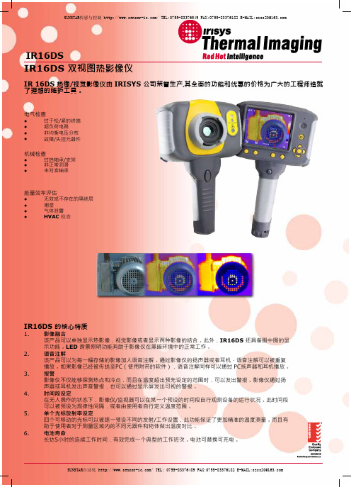
IR16DSIR16DS 双视图热影像仪IR 16DS 热像/视觉影像仪由 IRISYS 公司荣誉生产,其全面的功能和优惠的价格为广大的工程师造就了理想的维护工具。
电气检查● 过于松/紧的终端● 超负荷电路● 非均衡电压分布●故障/失控元器件机械检查● 过热轴承/支架● 非正常润滑● 未对准轴承能量效率评估● 无效或不存在的隔绝层● 潮湿● 气体泄露检查● HVACIR16DS 的核心特质1. 影像融合该产品可以单独显示热影像,视觉影像或者显示两种影像的结合。
此外,IR16DS 还具备图中图的显示功能。
LED 背景照明功能有助于影像仪在黑暗环境中的正常工作。
2. 语音注解该产品可以为每一幅存储的影像加入语音注解。
通过影像仪的扬声器或者耳机,语音注解可以被重复播放。
如果影像已经被传送至PC(使用附带的软件),语音注解同样可以通过 PC扬声器和耳机播放。
3. 报警影像仪不仅能够探测热点和冷点,而且在温度超出预先设定的范围时,可以发出警报。
影像仪通过扬声器或耳机发出声音警报,也可以通过显示屏发出可视的警报。
4. 时间段设定在无人操作的状态下,影像仪/监视器可以在某一个预设的时间段自行观测设备的运行状况。
此时间段可以被预设为规律性间隔,或者由使用者自行定义温度范围。
5. 单个光标放射率设定四个可移动的光标可以被逐一预设不同的发射/工作设置,此功能保证了更加精准的温度测量。
而且有助于使用者对于测量区域内的不同元器件和物体做出温度对比。
6. 电池寿命长达5小时的连续工作时间,有效完成一个典型的工作班次。
电池可替换可充电。
设置和控制●自动/用户设定的调整范围和级别控制● 读数单位°C, °F ● 四个可移动的温度测量光标且可以自行预设不同的发射设 置;光标可以显示两测量点之间的溫度差异●使用者可以预设每一个温测光标的发射设置● 自动搜寻测量区域内的热点/冷点● 可供使用者选择的反射温度补偿● 区域分析–三种选择● X-Y热轮廓/剖面显示● 显示溫度差异的等温线● 语音和文字注解● 影像采集,时间记录和日期记录● 视觉/听觉警告信息(超出/低于预设温度的状况)● 色盘选择● 可供用户选择的集中/综合功能● 影像综合控制:0至100%整幅图像/图中图状况的调整● 图像电子缩放功能(2倍,4倍)●多语言选择● 电池低电量指示● 具备图像浏览器,多图像显示和语音注解的重播● 时间或告警间隔的重置连接标准所储存的数据可通过SD 卡直接传送或者通过USB 线转接。
Fluke Ti10 热成像仪产品说明书

Thermal ImagingFluke Ti10 Thermal ImagerThe ultimate tool for troubleshooting and maintenanceThis thermal imager is the perfect tool to add to your problem solving arsenal. Built for tough work environments, this high-performance, fully radiometric infrared camera is ideal fortroubleshooting electrical installations, electro-mechanical equipment, process equipment, HVAC/R equipment and others.IR-Fusion® TechnologySee things both ways—infrared and visual (visible light) images fused togethercommunicating critical information faster and easier—traditional infrared images are no longer enough. IR-Fusion, a patent-pending technology that simultaneously captures a digital photo in addition to the infrared image and fuses it together taking the mystery out of IR image analysis. IR-Fusion is standard on Ti10 models.Technical DataFluke Ti25 and Ti10 Thermal ImagersThe perfect tools to add to your problem solving arsenal. Built for tough work environments, these high-performance, fully radiometric imagers are ideal for troubleshooting electrical installations, electro-mechanical equipment, process equipment, HVAC/R equipment and others.•All Fluke imagers come with enhanced prob-lem detection and analysis capabilities with IR-Fusion ® Technology. Simply scroll through the different viewing modes quickly to better identify trouble areas in Full IR thermal, picture-in-picture, or automatic blend visual and thermal images.• Optimized for field use in harsh work environments.• Engineered and tested to withstand a 2 m (6.5 ft) drop—When was the last time you dropped a tool?• Withstands dust and water—tested to an IP54 rating. • Delivers the clear, crisp images needed to find problems fast.• Identify even small temperature differences that could indicate problems with excellent thermal sensitivity (NETD).• Intuitive, three-button menu is easy to use—simply navigate with the push of a thumb.•No need to carry pen and paper—record findings by speaking into the camera. Voice annotations can be recorded with every image you take. Voicecomments are saved along with individual images for future reference (Ti25 only).• Everything needed to get started is included.• Adjustable hand strap for left-or right-handed use. •Manufactured in the U.S.A.Temperature Operating: -10 °C to 50 °C (14 °F to 122 °F)Storage: -20 °C to +50 °C (-4 °F to 122 °F) without batteries Relative humidity 10 % to 90 % non-condensingDisplay9.1 cm (3.6 in) diagonal landscape color VGA (640 x 480) LCD with backlight (selectable bright or auto)Controls and adjustmentsUser selectable temperature scale (°C/°F)Language selection Time/Date setEmissivity selection and Reflected Background Temperature Compensation (Ti25 only)User selectable Hot Spot and Cold Spot on the image (Ti25 only)Ti25 allows user to adjust palette, alpha blend, level, span, PIP, and emissivity on a captured image before it is stored.Software SmartView ® full analysis and reporting software includedPowerBattery: Internal rechargeable battery pack (included)Battery life: Three to four hours continuous use (assumes 50 % brightness of LCD)Battery charge time using ac adapter/charger and dc car charger: Two hours for full charge AC operation/charging AC adapter/charger (110 Vac to 220 Vac, 50 Hz to 60 Hz). Charges battery while imager is operating. Universal ac mains adapters included.Power saving Sleep mode activated after 5 minutes of inactivity, automatic power off after 20 minutes of inactivity Safety standards CE Directive: IEC/EN 61010-1 2nd Edition Pollution Degree 2Electromagnetic compatibility EMC directive: EN61326-1C-Tick: IEC/EN 61326US FCC: CFR 47, Part 15 Class A Vibration 2 G, IEC 68-2-29Shock25 G, IEC 68-2-29 (2 m or 6.5 ft drop, 8 sides)Dimensions (HxWxL)0.27 m x 0.13 m x 0.15 m (10.5 in x 5 in x 6 in)Weight 1.2 kg (2.65 lb)IP rating IP54Warranty Two-yearsCalibration cycle Two-years (assumes normal operation and normal aging)Supported languagesEnglish, Italian, German, Spanish, French, Russian, Portuguese, Swedish, Turkish, Czech, Polish, Finnish, Simplified Chinese, Traditional Chinese, Korean, and JapaneseFLUKE-Ti25 Thermal Imager FLUKE-Ti10Thermal ImagerIncluded with productThermal imaging camera w/20 mm lens, ac powersupply/battery charger (including mains adapters), SD memory card, SD card reader(USB) for downloading images into your computer, SmartView ® software with free software upgrades for life, rugged hard, carrying case, soft transport bag, hand strap, users manual, warranty registration card, interactive training DVD.Optional accessoriesFluke-TI Charger Thermal Imager Car ChargerFluke-T-VisorThermal Imager VisorFluke. Keeping your world up and running.®。
工业红外热成像仪操作规程

工业红外热成像仪操作规程1. 引言本操作规程用于指导工业红外热成像仪(以下简称成像仪)的正确使用和操作。
成像仪通过红外热感应技术,能够测量和显示物体表面的温度分布情况,提供实时热图和温度读数,广泛应用于工业领域的温度监测和故障排查。
2. 操作准备2.1 确保成像仪处于正常工作状态,检查电源和连接线是否正确连接并无损坏。
2.2 根据需要选择合适的测量模式和范围,设置温度单位为摄氏度或华氏度。
2.3 准备目标物体,确保其表面干净无障碍物影响成像结果。
2.4 在测量前进行环境调节,确保环境温度稳定,并排除干扰源。
3. 操作步骤3.1 打开成像仪,等待其启动并自检完成。
3.2 校准成像仪:在开机后的首次使用或在环境温度发生较大变化时,应进行校准操作。
按照设备说明书中的指引,将成像仪对准一个已知温度的参考物体,进行校准和调整。
3.3 对准目标物体:将成像仪对准欲测量的目标物体,调整焦距和成像范围,使其能够全面覆盖目标物体。
3.4 拍摄热图:通过成像仪的拍摄功能,获取目标物体的热图。
根据需要,可以设置连续拍摄、定时拍摄或手动拍摄等模式。
3.5 分析和记录:对得到的热图进行分析和评估,查看温度分布、异常区域等。
在需要时,可以进行温度测量和标记等操作。
将重要的数据和结果记录下来,以备后续分析或报告使用。
3.6 关闭成像仪:在完成操作后,及时关闭成像仪,断开电源和连接线。
4. 注意事项4.1 操作人员应具备相关的培训和操作经验,熟悉设备的使用方法和安全规范。
4.2 操作过程中,应注意安全防护,避免直接触摸高温物体或受伤。
4.3 使用前后应定期检查和清洁成像仪,保持其外观整洁和正常工作状态。
4.4 如果发现成像仪出现故障或异常情况,应立即停止使用并通知维修人员进行检修。
4.5 本操作规程仅适用于常规情况下的成像仪操作,对于特殊或复杂的应用场景,请按实际需要制定相应的操作指引。
5. 结束语本操作规程旨在保证工业红外热成像仪的正确使用和操作,提高工作效率和安全性。
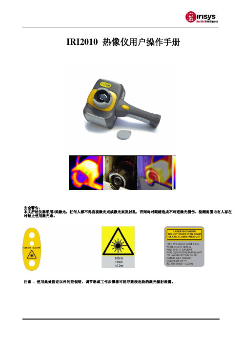
IRI2010热成像仪中文用户手册

IRI2010 红外热像仪用户手册! 警告、小心和注意定义!警告代表可能导致人身伤害或死亡的危险情况或行为。
!小心代表可能导致热像仪受损或数据永久丢失的情况或行为。
!注意代表对用户有用的提示信息。
重要信息–使用仪器前请阅读!警告–本仪器内置激光发射器,切勿凝视激光束。
激光规格为635 nm, 0.9mW, 二级。
!小心–因热像仪使用非常灵敏的热感应器,因此在任何情况下(开机或关机)不得将镜头直接对准强烈幅射源(如太阳、激光束直射或反射等),否则将对热像仪造成永久性损害!!小心 - 运输期间必须使用原配包装箱,使用和运输过程中请勿强烈摇晃或碰撞热像仪。
!小心–热像仪储存时建议使用原配包装箱,并放置在阴凉干燥,通风无强烈电磁场的环境中。
!小心-避免油渍及各种化学物质沾污镜头表面及损伤表面。
使用完毕后,请盖上镜头盖。
!小心 -为了防止数据丢失的潜在危险,请经常将数据复制(后备)于计算机中。
!注意 -在精确读取数据前,热像仪可能需要3-5分钟的预热过程。
!注意 -每一台热像仪出厂时都进行过温度校正,建议每年进行温度校正。
!小心 -请勿擅自打开机壳或进行改装,维修事宜仅可由本公司授权人员进行。
目录! 警告、小心和注意 (2)1简介 (5)1.1标准配置 (7)1.2可选配置 (7)2热像仪简介 (8)2.1功能键 (8)2.2接口 (11)3基本操作 (12)3.1电池安装及更换 (12)3.1.1电池装卸 (12)3.1.2更换电池 (13)3.2电池安全使用常识 (14)3.3快速入门 (15)3.3.1获取热像 (15)3.3.2温度测量 (15)3.3.3冻结和存储图像 (16)3.3.4回放图像 (17)3.3.5导出存储的图像 (17)4操作指南 (18)4.1操作界面描述 (18)4.1.1工作界面 (18)4.1.2主菜单 (19)4.1.3对话框 (19)4.1.4提示框 (20)4.2测温模式 (20)4.3自动/手动 (21)4.4设置 (22)4.4.1测温设置 (22)4.4.2测温修正 (23)4.4.3分析设置 (24)4.4.4时间设置 (25)4.4.5系统设置 (25)4.4.6系统信息 (27)4.4.7出厂设置 (27)4.5文件 (28)4.5.1打开 (28)4.5.2存储 (29)4.5.3存储设置 (31)4.5.4自动存储 (32)4.5.5删除 (32)4.5.6格式化 (33)5技术规格 (35)故障对策 (37)附录 A (38)常用材料的比辐射率(仅供参考) (38)附录B (39)出厂设置参数表 (39)1简介感谢您选择我公司的IRI2010手持式红外热像仪。
红外线热成像仪使用方法说明书

红外线热成像仪使用方法说明书使用方法说明书红外线热成像仪1. 引言红外线热成像仪(以下简称热成像仪)是一种重要的热像仪器,利用红外线辐射能量来检测目标物体的表面温度,通过生成热图来显示目标物体的热分布情况。
本使用方法说明书将为您介绍热成像仪的使用方法,帮助您更好地了解和操作该设备。
2. 设备准备在使用热成像仪之前,请确保已完成以下准备工作:2.1 检查设备仔细检查热成像仪的外观是否完好无损,是否有明显损坏或松动的零部件。
如有发现异常情况,请立即联系售后服务部门进行维修或更换。
2.2 电源连接将热成像仪的电源适配器插头与设备电源插座相连接,确保插头紧固可靠。
然后将电源适配器的插头插入交流电源插座,确保插座能够正常供电。
2.3 电池安装(可选)如果热成像仪配备了可充电电池,您可以选择安装电池。
先打开设备的电池仓盖,按照指示方向正确地插入电池,并确保电池与设备的接触良好。
然后重新安装电池仓盖并锁紧。
3. 设备操作3.1 开机与闭机操作热成像仪前,请先确保设备已经连接电源或安装了电池。
要开机,轻按设备上的电源键,并耐心等待设备启动。
启动时,热成像仪的显示屏将逐渐显示相应的启动画面,待画面显示完毕后,设备即可正常使用。
要闭机,长按设备上的电源键,直至屏幕显示关机画面。
然后松开电源键,并确认关闭设备。
3.2 菜单设置热成像仪配备了一系列可供用户自定义设置的菜单功能。
通过操作设备的菜单,您可以调整图像显示效果、选择测温模式等。
要进入菜单设置界面,您可以按下设备上的菜单键或相应的功能快捷键。
在菜单界面中,您可以通过按键或屏幕触摸来选择和调整各种参数。
待参数设置完成后,按下“确认”键即可保存并应用设置。
3.3 温度测量为了获得目标物体的温度信息,您需要使用热成像仪的温度测量功能。
在正常操作状态下,将热成像仪对准目标物体,确保图像显示屏上能够清晰看到目标物体的热分布图。
然后使用设备上的测温功能键或触摸屏上的测温图标,选择相应的测温模式(单点测温、多点测温、波动测温等)。
热成像仪操作规程百度文库
热成像仪操作规程百度文库《热成像仪操作规程》一、引言热成像仪是一种可以利用红外线来观察并记录物体的热分布情况的设备。
在工业领域和科研领域,热成像仪被广泛应用,可以用来检测设备的性能、探测能源损耗、识别故障等。
为了确保热成像仪的准确性和安全性,在操作时需要按照规程进行操作。
本文将介绍热成像仪的操作规程。
二、操作规程1. 准备工作:a. 确保热成像仪处于停机状态;b. 检查设备的电源和电缆,确保其正常工作;c. 确保环境温度适宜,不要过于寒冷或过热;d. 穿戴好相关的个人防护设备,如手套、护目镜等。
2. 启动设备:a. 按照设备的启动步骤,依次打开电源开关;b. 等待设备自检完毕,确保设备无故障。
3. 设置参数:a. 根据需要调整热成像仪的参数,如温度范围、颜色调节等;b. 确保设置的参数符合实际需求,能够准确观测所需物体的热分布情况。
4. 操作技术:a. 熟练掌握热成像仪的使用方法,包括对焦、拍摄角度等;b. 注意观察监测对象的热分布情况,对于异常情况及时记录。
5. 关闭设备:a. 在使用完毕后,按照设备的关机步骤进行操作;b. 关闭电源开关,将设备断电。
6. 清洁维护:a. 每次使用后,清洁热成像仪的镜头和外壳,确保设备整洁;b. 定期维护设备,保证其正常工作。
三、注意事项1. 在操作热成像仪时,要注意保持设备和工作环境的干净整洁,避免灰尘和杂物进入设备;2. 使用前要对热成像仪进行检查,确保设备无故障;3. 操作过程中要注意设备的安全,防止碰撞和摔落;4. 在操作过程中,保持注意力集中,避免产生危险事故。
通过遵守以上操作规程和注意事项,可以更好地保证热成像仪的准确性和安全性,提高工作效率,确保设备的长期稳定运行。
建筑热像仪 Irisys IRI4015 使用指南说明书

IRI4015Thermal Imager for BuildingsFor the identification and diagnosis of issues that can cause energy loss, damage, unscheduled machine down time and ultimately increased costs in buildingsWho should use a Building ThermalImagerBuilding inspectorsFacility managersBuilding surveyorsEnergy loss auditorsCommercial refrigeration engineersBuilding and services maintenance teamsWhy should you use it?Understand where your building islosing energy through ill fitting windows, doorswalls and roofingQuickly assess where insulation is missing or non-existentDetect potential hidden dangers such as areasof damp collection in roofs and walls orvermin infestation in older buildingsHighlight areas of thermal bridgesProduce energy audits and building diagnosticsTo become an integral part of the electrical andmechanical predictive and preventative maintenance regimeWhy use the Irisys IRI4015?Compact and easy to usePortable with long life rechargeable batteryHighest thermal sensitivity (NETD ≤50mK) in its price rangeBest screen resolution (160x120 pixels) in its classCan store over 1,000 images on supplied SD cardAutomatic temperature lock (to both hottest and coldest point) visible onthe screenInstant on-screen temperature differential displayFull analysis and report writing software includedVery robust - Tested for vibration, shock and dropMinimal cost of ownershipSETTINGS AND CONTROLS• On/Off soft power control.• User selectable span control • User selectable level control • Auto adjust span and level• Display palettes: rainbow, ironbow, high contrast and greyscale.• Laser trigger switch.• Readout in ºC, ºF or K.• Image capture, time and date.• 2 x digital zoom.INTERFACES USB type BIMAGER POWER SUPPLYBattery: Lithium-ion field rechargeable,replaceable battery with up to 6 hours continuousoperation.AC operation:AC adaptor suppliedMECHANICALHousing: Impact Resistant PlasticDimensions: 230mm x 120mm x 110mm Weight: 0.75Kg including battery.Mounting:Can be handheld or mounted on a tripod.ENVIRONMENTTemp: operating range -15°C to+50°C; storage range:-20°C to +70°C Humidity: 10% to 90% non-condensing CE Mark (Europe)Operating temp for stated accuracy: 23ºC Vibration: MIL-PRF-288—F Class 2 section 4.5.5.3.1Shock: MIL-PRF-288—F Class 2 section 4.5.5.4.1Drop test: MIL-PRF-288—F Class 2 section 4.5.5.4.2IP rating: IP42The Irisys IRI4015 Building Thermal Imager Pack Includes:IR Camera, battery, AC adaptor, USB cable, car charger, CD with user manual and software(PC analysis and report writer), light shade, carrying case, wrist straprubber protector, SD card and SD card readerInfraRed Integrated Systems LimitedPark Circle, Tithe Barn Way, Swan Valley, Northampton, NN4 9BG. UKTel: +44 (0) 1604 594 200Fax: +44 (0) 1604 594 210Email: ***************.uk Web site: © 2010 InfraRed Integrated Systems Limited (Irisys). No part of thispublication may be reproduced without prior permission in writing from Irisys. Whilst Irisys will endeavor to ensure that any data contained in this product information is correct, Irisys do not warrant its accuracy or accept liability for any reliance on it. Irisys reserve the right to change the specification of the products and descriptions in this data sheet without notice. Prior to ordering products please check with Irisys for current specification details.This product may be protected by patents EP 0 853 237 B1 and US 6,239,433 BI and other patents pending. All brands and product names are acknowledged and may be trademarks or registered trademarks of their respective holders.September 2010IPU 40318Issue 1Authorised Irisys Distributor:TECHNICAL SPECIFICATIONPERFORMANCEField of view (FOV): 20°x15°Focus: Manual Minimum Focus: 30cm.Spectral Response: 8µm to 14μmThermal Sensitivity: NETD≤50mK(0.05°C)@ 23°C ambient and 30°C scene temp Detector: 160 X 120 Pixelsuncooled microbolometer . MEASUREMENTTemperature range: -20°C to +125°C.Radiometry: Two moveable temperature measurement cursors givingautomatic temperature differencemeasurement and auto lockingonto hottest and coldest points.Emissivity Correction: User selectable 0.1 to 1.0 in steps of 0.01 with reflected ambient temperature compensation.Accuracy: The greater of ±2°C or ±2% of reading in °CDISPLAY3½” colour LCD with LED backlight and 4 colour palettes.IMAGE STORAGE Over 1000 images on supplied SD card (MMC or SD card compatible).LASER POINTER A built in Class 2 laser to highlight the centre of the imaged area FEATURES• Real time image and temperature measurement display.• Auto hot/cold seeker• Crisp high resolution images • Large 3½” display • Simple operation• Multiple temperature measurement• Multiple image storage and retrieval at full digital resolution• Image browser with full image adjustment • Battery charge indicator • Lightweight。
热像仪中文说明书
音频设置 ..........................................................................................................................................13
5.5.
图像浏览器 .......................................................................................................................................14
e) 保存图像
图像保存按钮
要保存动态或静态图像,按保存按钮一次。 如果标题模式或语音注释已被打开,可添加文本标题或语音注释到图像中 (见第6节)。请注意热键3可用于在动态图像与静态图像之间切换。
6
f) 温度测量 温度读数显示在显示屏的最上方。在默认模式下,一个以℃单位显示的温度为光标中央点的温度。屏幕最上方的其它读
5.3.
相机设置 ..........................................................................................................................................12
5.4.
a) 100% 红外图像
b) 100% 可见光图像
c) 50%红外图像与50%可见光图像
中央切换按钮 上/下、左/右导航键
热键1
热键2
热键3
热键4
1. 按下热键2
直到可见光图像的打开/关闭图标出现
热成像仪使用手册说明书
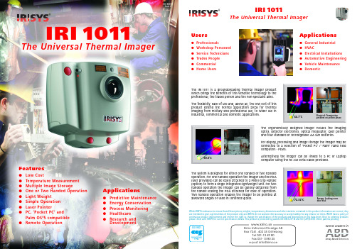
®The Universal Thermal Imager IRI1011Features●Low Cost●Temperature Measurement●Multiple Image Storage●One or Two Handed Operation ●Light Weight●Simple Operation●Laser Pointer●PC, ‘Pocket PC’ andPalm OS®5 compatible●Remote Operation Applications●Predictive Maintenance●Energy Conservation●Process Monitoring●Healthcare●Research andDevelopmentIPU40057Issue 2IRI1011The Universal Thermal ImagerElectrical: Terminationproblem on yellow phase®The IRI1011 is a groundbreaking thermal imager productwhich brings the benefits of this versatile technology to theprofessional, the trades person and the non-specialist alike.The flexibility, ease of use and, above all, the low cost of thisproduct extend the normal application areas for thermalimaging from military and professional use, to wider use inindustrial, commercial and domestic applications.Whilst IRISYS endeavour to ensure that all descriptions, weights, temperatures, dimensions and other statistics contained in this product information are correct, theyare intended to give a general idea of the product only and IRISYS do not warrant their accuracy or accept liability for any reliance on them. IRISYS have a policy ofcontinuous product improvement and reserve the right to change the specification of the products and descriptions in this data sheet. Prior to ordering productsplease check with IRISYS for current specification details. This product is protected by patents EP 0 853 237 BI and US 6,239,433 BI. Other patents pending.Energy: Leaking ovendoor seal66.7˚C72.32˚C50.5˚CABDWorld Leaders inArray-Based DetectorsApplications●General Industrial●HVAC●Electrical Installations●Automotive Engineering●Vehicle Maintenance●DomesticUsers●Professionals●Workshop Personnel●Service Technicians●Trades People●Commercial●Home UsersProduct DescriptionThe ergonomically designed imager houses the imaging optics, detector, drive electronics, optical modulator,laser pointer and four standard or rechargeable AA size batteries. The system includes an optional pistol grip handle which holds virtually any ‘Pocket PC’or compatible ‘Palm’device as a combined processing, display unit and image storage device. As an alternative, the output of the imager can be displayed and processed in real time using a PC.OperationThe system is designed for either one or two handed operation. For one handed operation both the imager and the user provided ‘Pocket PC’/ ‘Palm’device can be attached to the handle to form a single integrated lightweight unit. For two handed operation the imager can be quickly detached from the handle leaving the ‘Pocket PC’/ ‘Palm’device attached for ease of operation. This latter configuration enables the imager to be pointed at awkward angles or used in confined places. Alternatively, instead of using a ‘Pocket PC’/ ‘Palm’device the imager can be linked to a PC or laptop computer using the RS232 serial cable supplied.Feb 2004IPU 40055 issue 2IRI 1011Universal Thermal ImagerThe IRI 1011 is a groundbreaking thermal imager product which brings the benefits of this versatile technology to the professional, the trades person and the non-specialist alike.The flexibility, ease of use and above all, the low cost of this product extend the normal application areas for thermal imaging from military and professional use, to wider use in industrial,commercial and domestic applications .Typical applications for the IRI 1011 include:Predictive and Preventative Maintenance Process MonitoringResearch and Development HV AC Troubleshooting Vehicle MaintenanceGeneral Industrial/Domestic......ABDWorld Leaders inArray-Based DetectorsThe IRI 1011 Universal Thermal ImagerPERFORMANCETemperature Measurement range:-10˚C to +300˚C Field of view (FOV):20˚x 20˚Spectral Response:8 to 14 micrometers Sensitivity:0.3K @ 30˚C Displayed Image:96 x 96 pixels Detector:16 x 16 pixel array Frame rate:8HzIMAGE STORAGEUp to 1000 images per MB of SER POINTERA built in Class II laser is supplied to highlight the reference pixel.IMAGER POWER SUPPLYBattery: 4 x AA type removable batteries.Operation time:Up to 8 hours.AC operation:AC adaptor, supplied.MECHANICALHousing: Impact Resistant Plastic.Dimensions: 120mm x 125mm x 80mm.Weight:< 600g not including ‘Pocket PC’/‘Palm’device and handle.Mounting: Handheld & Tripod mounting.IRI 1011 INCLUDESImager, software for ‘Pocket PC’, ‘Palm’& PC,2m RS232 connection cable - imager to PC, user manual, AC power supply, carrying case.OPTIONA pistol grip handle for attaching imager and ‘Pocket PC’/ ‘Palm’Device for single handed operation.SPECIFICATIONABDWorld Leaders inArray-Based DetectorsWhilst IRISYS endeavour to ensure that all descriptions, weights, temperatures, dimensions and other statistics contained in this product information are correct, they are intended to give a general idea of the product only and IRISYS do not warrant their accuracy or accept liability for any reliance on them. IRISYS have a policy of continuous product improvement and reserve the right to change the specification of the products and descriptions in this data sheet. Prior to ordering products please check with IRISYS for current specification details. This product is protected by patents EP 0 853 237 B1 and US 6,239,433 B1. Other patents pending.All brands and product names are acknowledged and may be trademarks or registered trademarks of their respective holders.ENVIRONMENT Temp. operating range:-5˚C to +50˚C Humidity:10% to 90% non condensing Temp. storage range:-20˚C to +80˚CCE Mark (Europe):Complies with EMC directiveSETTINGS AND CONTROLS:User selectable sensitivity er selectable offset control (range).Auto adjust sensitivity/range.Display palettes: red/blue, green/blue and greyscale.‘Pocket PC’/ ‘Palm’device: two moveable temperature measurement cursors.PC: up to ten moveable temperature measurement cursors.User selectable emissivity values.User selectable image integration: 1 to 10 frames.Readout in ˚C, ˚F and K.Image snapshot.Image label.FEATURES - ‘POCKET PC’/ ‘PALM’SOFTWAREReal time image and temperature measurement display Multiple image storage and retrieval.Image browser.Battery Charge indicator‘Pocket PC’/ ‘Palm’device controlled by navigator button and touch sensitive screen controls. Reflected ambient temperature compensation.Temperature difference measurement.FEATURES - PC SOFTWAREMultiple image storage and retrieval.Time / Temperature display for up to ten user defined pixels.Save all 256 temperature values to Microsoft Excel.Cut & Paste images into other Microsoft applications.Reflected ambient temperature compensation.Real time image and temperature measurement display COMPUTER REQUIREMENTSPocket PC: Compatible with most ‘Pocket PC’devices running Microsoft ‘Pocket PC’2000, 2002 and 2003. e.g. HP iPAQ 2210, O2 XDA - contact IRISYS for alternatives. RS 232 to ‘Pocket PC’communication cable or CompactFlash RS 232 adaptor where applicable.Palm :Palm devices conforming to OS5 or higher, double density screen, 320 x 320 display resolution.eg. Palm Zire 71, Palm Tungsten T.PC :IBM compatible PC with a minimum of:32Mb RAM, 300MHz processor, MS Windows (98,NT, ME, 2000 and XP), RS 232 serial port (115k Baud),16 bit colour graphics capability.........................CAUTIONCLASS II LASER PRODUCT635nm 0.9mW。
热像仪使用说明书
热像仪使用说明书一、简介热像仪是一种用于检测物体表面温度分布的工具。
它通过测量红外辐射能量来绘制热图,用于定位热点、缺陷、漏热等问题。
热像仪在许多领域,如建筑、电力、安防等,有着广泛的应用。
本使用说明将为您介绍如何正确使用热像仪。
二、安全注意事项1. 在使用热像仪前,请确保已经阅读并理解本使用说明书,遵守所有的使用和安全指引。
2. 确保热像仪正常工作前,检查设备是否损坏、电池是否充足,确保工作环境无明显的险情。
3. 在测量过程中,避免将热像仪的光束直接照射到人眼、动物或其他有可能受到伤害的物体上。
三、热像仪的使用步骤1. 打开电源:a. 按下电源按钮,热像仪将开始自检过程;b. 若开机成功,屏幕将显示相关界面并显示当前环境温度。
2. 调整设置:a. 使用热像仪菜单功能按钮进入设置选项;b. 根据需要,设置温度单位、色带、距离系数等参数;c. 确认设置后,退出设置菜单。
3. 目标测温:a. 确保热像仪与目标保持适当距离(根据设备型号和测量要求而定);b. 瞄准目标,按下测温按钮,等待热像仪完成测量过程;c. 热像仪将在屏幕上显示实时红外图像和表面温度。
4. 数据分析:a. 通过观察红外图像,分析目标的热分布、热点等关键信息;b. 使用热像仪附带的软件或其他数据处理工具进行图像分析和报告生成;c. 根据需要,保存测量数据和相关图像。
5. 关机:a. 使用热像仪的电源按钮,按下关机;b. 确认关闭所有功能后,将热像仪放置在适当的存储位置。
四、注意事项1. 热像仪是一种精密仪器,在使用过程中请避免严重的撞击、震动或摔落,以免引起设备故障。
2. 避免使用热像仪在含有易燃气体或有爆炸风险的场所,确保工作环境安全。
3. 若发现热像仪出现异常,如屏幕故障或无法正常拍摄图像等问题,请及时联系相关维修人员进行处理。
4. 在存储热像仪时,请保持设备干燥、通风,并避免存放在过于高温或低温的环境中。
五、常见问题解答Q: 热像仪在使用过程中发热,是否正常?A: 是的,热像仪在工作时会产生一定的热量,一般情况下属于正常现象,但不应过度发热。
热成像仪说明书

Ti100, Ti105, Ti110, Ti125, TiR105, TiR110, TiR125Thermal Imagers使用手冊February 2012, Rev.1, 2/13 (Traditional Chinese)© 2012-2013 Fluke Corporation. All rights reserved.Specifications are subject to change without notice.All product names are trademarks of their respective companies.有限保證和有限責任Fluke公司保證每一個產品在正常使用和維修情況之下毫無材料及工藝上的瑕疵。
保固期為自購買產品之日算起三年。
零件、產品修理和服務有90天的保證。
本保證只適用於Fluke授權零售商的原始買方或終端使用者客戶,恕不適用於保險絲、拋棄式電池或任何被Fluke認定為由於誤用、改造、疏忽、污染、意外或不正常操作和使用的產品。
Fluke保證軟體能在大致符合產品功能性規格的條件下運作至少90天,而且軟體是正確無誤地錄製在毫無瑕疵的媒體上。
Fluke並不保證軟體完全沒有任何錯誤或操作不會中斷。
Fluke授權零售商只能為終端使用者客戶所購買的新產品或未使用過的產品提供保證,零售商無權代表Fl uke提供更大的或不同的保證。
Fluke所提供的保固支援只適用於透過Fluke授權直銷商處購買的產品或買方按適當的國際價格購買的產品。
在一個國家購買的產品被送往另一個國家接受修理時,Fluke保留向買方徵收修理和更換零部件的進口費用的權利。
Fluke的保證責任是有限的,Fluke可以選擇是否依購買價格退款、免費修理或更換在保固期內退還給Flu ke授權維修中心的瑕疵產品。
如欲獲得保證服務,請與您附近的Fluke授權維修中心聯絡以取得送還產品的授權資訊,然後將產品附上故障說明、郵資和預付保險金(目的地交貨)送到您附近的Fluke授權維修中心。
- 1、下载文档前请自行甄别文档内容的完整性,平台不提供额外的编辑、内容补充、找答案等附加服务。
- 2、"仅部分预览"的文档,不可在线预览部分如存在完整性等问题,可反馈申请退款(可完整预览的文档不适用该条件!)。
- 3、如文档侵犯您的权益,请联系客服反馈,我们会尽快为您处理(人工客服工作时间:9:00-18:30)。
IRI2010 红外热像仪用户手册! 警告、小心和注意定义!警告代表可能导致人身伤害或死亡的危险情况或行为。
!小心代表可能导致热像仪受损或数据永久丢失的情况或行为。
!注意代表对用户有用的提示信息。
重要信息–使用仪器前请阅读!警告–本仪器内置激光发射器,切勿凝视激光束。
激光规格为635 nm, 0.9mW, 二级。
!小心–因热像仪使用非常灵敏的热感应器,因此在任何情况下(开机或关机)不得将镜头直接对准强烈幅射源(如太阳、激光束直射或反射等),否则将对热像仪造成永久性损害!!小心 - 运输期间必须使用原配包装箱,使用和运输过程中请勿强烈摇晃或碰撞热像仪。
!小心–热像仪储存时建议使用原配包装箱,并放置在阴凉干燥,通风无强烈电磁场的环境中。
!小心-避免油渍及各种化学物质沾污镜头表面及损伤表面。
使用完毕后,请盖上镜头盖。
!小心 -为了防止数据丢失的潜在危险,请经常将数据复制(后备)于计算机中。
!注意 -在精确读取数据前,热像仪可能需要3-5分钟的预热过程。
!注意 -每一台热像仪出厂时都进行过温度校正,建议每年进行温度校正。
!小心 -请勿擅自打开机壳或进行改装,维修事宜仅可由本公司授权人员进行。
目录! 警告、小心和注意 (2)1简介 (5)1.1标准配置 (7)1.2可选配置 (7)2热像仪简介 (8)2.1功能键 (8)2.2接口 (11)3基本操作 (12)3.1电池安装及更换 (12)3.1.1电池装卸 (12)3.1.2更换电池 (13)3.2电池安全使用常识 (14)3.3快速入门 (15)3.3.1获取热像 (15)3.3.2温度测量 (15)3.3.3冻结和存储图像 (16)3.3.4回放图像 (17)3.3.5导出存储的图像 (17)4操作指南 (18)4.1操作界面描述 (18)4.1.1工作界面 (18)4.1.2主菜单 (19)4.1.3对话框 (19)4.1.4提示框 (20)4.2测温模式 (20)4.3自动/手动 (21)4.4设置 (22)4.4.1测温设置 (22)4.4.2测温修正 (23)4.4.3分析设置 (24)4.4.4时间设置 (25)4.4.5系统设置 (25)4.4.6系统信息 (27)4.4.7出厂设置 (27)4.5文件 (28)4.5.1打开 (28)4.5.2存储 (29)4.5.3存储设置 (31)4.5.4自动存储 (32)4.5.5删除 (32)4.5.6格式化 (33)5技术规格 (35)故障对策 (37)附录 A (38)常用材料的比辐射率(仅供参考) (38)附录B (39)出厂设置参数表 (39)1简介感谢您选择我公司的IRI2010手持式红外热像仪。
型号识别IRI2010热像仪采用25um 160*120探测器,测温范围-20°C~+350°C 功能热像仪包含以下功能:自动或手动控制色标温度范围°C, °F 和 K 测量单位11种语言可选择最热点测量最冷点测量4个可移动点测量11种色标可选择3个区域测温2 条线测温高温报警设置背景温度修正2倍数字变焦冻结当前图像视频输出-NTSC 或PAL制TF卡图像存储CMOS可见光图像和储存语音注释等温报警温度修正内置常见材料比辐射率选择表升级选项IRI2010可升级使用长焦或广角镜头。
主要应用:预防性维护●电力工业:输电线、电力设备热状态检查,故障缺陷诊断。
●电气系统:在电路过载发生之前预先识别。
●机械系统:减少停机时间和防止故障。
建筑科学●屋顶:快速高效地探测和查出渗水现象。
●建筑结构:对商用楼和住宅楼进行红外能量评估调查。
●潮湿探测:找到潮湿和发霉的根源。
●修复:评估补救措施,确保区域完全干燥。
其他应用●钢铁工业:炼钢、轧钢过程的监控,热风炉破损的诊断,出炉板胚温度检测等。
●消防:森林防火及潜在火源寻找,特种材料自燃预防检测,电气防火安全检测。
●医学:人体体表温度检测及温度场分布分析。
●石化工业:输油管道状态检查,物料界面的检测,热泄漏及保温结构、动力设备状况的检测等。
1.1标准配置●红外热像仪(扶手带)●携带箱●视频输出线●锂电池(2)●锂电池充电器●镜头盖●用户手册、报表分析系统光盘●TF卡(8G)●TF 读卡器●USB线1.2可选配置●0.5倍镜广角扩展镜头●2倍镜长焦扩展镜头●遮阳罩●电源适配器(含电源线)●欧规、英规和澳规插头●用户手册、报表分析系统说明书●便携背包2热像仪简介2.1功能键2 31456 7[1] 电源开关用于热像仪的开启和关闭。
按此开关超过三秒,启动/关闭热像仪。
! 注意:关机后,再次开机建议至少等待十秒钟,以确保热像仪的安全。
[2] 选择/自动键(标记A)标记A的按键有以下两种功能。
a)第一个功能是修改选定的参数。
通过快速的按下(小于2秒)和松开按钮执行该功能,修改选定的参数。
以后每按压一次该键可选择下一个参数,被选中的参数将以黄色标记。
该功能包括:•测温点、线和区域点和线 - 按方向键可移动它们的位置。
按菜单键会弹出属性框,按“C”键可删除选择的测温对象。
区域–按菜单键弹出所选择区域的属性框。
在属性框中,用户选择区域的位置或大小,然后可用方向键移动区域位置或调整区域大小。
•色标选中色标时,按左右键切换可选择的色标,色标名称显示在色标上方。
被选择的色标大约三秒后成为当前图像的色标,并作为下次开机的默认色标。
•色标上下限值选中色标上下限时,按左右键增减色标条上下限温度范围;按上下键,平移色标对应的温度区间。
如果在自动模式下修改其中任何一个参数将变为手动模式。
b)第二个功能是强制调零。
按A键5秒以上,热像仪将自动校正以获得精确的测量。
[3] 取消/可见光键(标记C)•菜单模式时,按该键取消当前的菜单操作。
•图像冻结或回放时,按该键将回到动活动模式。
•在非菜单和参数修改模式下,按该键将在热像和可见光图像间进行切换。
•当选中测量参数时,如测量点,按该键将删除该测量参数。
[4] 冻结/保存键(标记S)用来冻结或保存图像。
按一次该键将冻结图像,按确认键将保存图像,按取消键将返回到活动模式,保存图像时,若语音注释功能开启,将弹出语音注释对话框。
[5] 菜单/确认键包括上、下、左、右和菜单/确认(中间)键。
在不同操作模式下具有不同的功能。
在菜单模式,用于菜单选择,上下键用于同级菜单操作,左右键用于不同级菜单间操作,确认(中间)键用于激活菜单和确认选择。
在图像模式时,上下键用于2倍数字放大和返回正常图像操作。
2倍数字放大时,屏幕左上角会显示“X2”。
在选中测温点时,按菜单键弹出属性对话框,按四个方向键移动点位置。
在选中测温线时,按确认键弹出属性对话框。
如果测温线是横线,按上下键移动测温线位置;按左右键移动参考线位置。
如果测温线是竖线,按左右键移动测温线位置;按上下键移动参考线位置。
在选中测温区域时,按确认键弹出属性对话框。
根据属性对话框中选择区域位置或大小,按四个方向键进行区域位置移动或区域大小改变。
[6] 扳机/快捷键扳机键作为自定义快捷键,可定义为以下功能:激光开关–按下此键开启激光,放开关闭激光。
测温点–按一下增加测温点,再按一下删除测温点。
测温区域–按一下增加测温区域,再按一下删除测温区域。
图像保存–同S键,按一下开始图像保存操作。
图像切换 - 按一下在热像和可见光图像之间切换。
[7] 麦克风用于保存图像时进行语音注释,详见4.5.3节。
2.2接口1234[1] USB线输出接口此接口通过USB线可与计算机相连传输数据,支持USB2.0。
[2] TF卡槽使用标准TF卡,如随机配置的8G容量TF卡,用于仪器升级及保存图像。
[3] 视频输出用于视频输出。
[4] 电源接口外接电源输入接口,电源要求为DC12V,中心插头为正极。
3基本操作3.1电池安装及更换3.1.1电池装卸电池仓在仪器手柄内。
推动电池盖底部的推纽,扳开电池扣后即可装卸电池。
插入电池时,请注意电池带触点的一端先插进电池仓。
将电池盖合上,听到“啪”一声后,就可使用仪器。
! 注意:仪器应使用标准配置的电池,否则可能因电池尺寸和电压不正确,而损坏仪器的机械或电气性能。
3.1.2更换电池当电池大约剩余5%电量时,仪器将显示提示信息,并在约3秒后关机。
显示关机此时应更换电池。
3.2电池安全使用常识➢电池应尽可能保存在-20℃∽20℃环境温度下,因电池在储存期间存在少量的自放电现象,为避免电池在储存期间可能产生的过放电而影响电池容量,电池应充满电保存,并每隔一定时间进行一次充电。
时间间隔如下:●环境温度为-20℃∽20℃,每6个月一次;●环境温度为20℃∽45℃,每3个月一次;●环境温度为45℃∽60℃,每1个月一次。
每次充电电量必须大于电池容量的50%以上。
➢电池应在0℃∽40℃环境温度下充电,在0℃环境温度下充电会减少电池容量,在40℃以上充电时可能会使电池温度过高并造成损坏。
! 警告:! 请勿拆解、挤压、刺戳电池;! 请勿使电池外部触点短路;! 保持电池干燥,勿置于火中或水中;! 请勿放置在儿童易触及处;! 请按照当地政府规定处置废弃电池。
3.3快速入门3.3.1获取热像●安装好电池后,按热像仪电源开关(大于3秒)直至出现开机画面。
大约50秒后,仪器初始化完成,进入工作状态。
●打开镜头盖,对准目标,调节热像仪镜头的焦距,使目标成像清晰。
! 注意:调焦不清晰,会导致测量错误。
3.3.2温度测量●如果在屏幕上没有测温对象,按菜单键并选择测温模式,添加测温点、线或/和区域。
按确认键和左右键选择适合的测量参数。
将屏幕光标对准所测目标,目标对象的温度将会显示在屏幕的右上方。
为了得到高精确的测量,可长按A键5秒以上,至屏幕左上角显示“校正”字样,进行自动校正。
●欲对当前热像进行详细测温,可按“S”键冻结图像,然后在屏幕上进行分析。
如果以后还需要分析,可以将热像保存下来,见第4章。
●当目标温度大于或小于热像仪测温档位所对应的上限或下限温度时,屏幕温度将显示>XXX℃或<XXX℃,XXX代表所选档位的上限或下限温度。
●如果需要修改测温对象的属性,选中该测温对象,然后按确认键,屏幕上则弹出该测温对象的属性对话框。
以下界面分别是测温点、测温线、测温区域的属性对话框。
测温点的属性可以设定比辐系数和参考点。
当“设为参考”选项更改为“是”时,其它测温对象显示的温度值为与该测温点的温差。
测温线的属性只能设定比辐系数。
测温区域的属性可以设定比辐系数、是否设为参考、区域的测温类型(最高温度、最低温度或平均温度)以及区域移动的参数(区域位置或大小,并通过方向键调整)。
当“设为参考”选项更改为“是”时,其它测温对象显示的温度值为与此区域测温结果的温差。
3.3.3冻结和存储图像按“S”键冻结图像,按“C”键退出冻结。