CATIA汽车摩托车企业设计人员内部培训资料CATIAA级曲面检查规范说明OK
catia培训教程资料PPT教案

获取工具栏图标的联机帮助
恢复上次撤消的操作
撤消操作
粘贴对象
拷贝对象
剪切对象
不作打印设置快速打印文档
保存文档
打开已有文档
产生新文档
视图工具栏(View Toolbar)
包括三种模式:缺省的视图工具栏
行走模式工具栏(Walk mode)
飞行模式工具栏(Fly mode)
CATIA 用户界面
CATIA软件的用户界面分为五个区域:顶部菜单区(Menus)左部为产品/部件/零件树形结构图,或称为“历史树”(Tree & associated geometry)中部图形工作区(Graphic Zone)右部为与选中的工作台相应的功能菜单区(Active work bench toolbar)下部为标准工具菜单区(Standard Toolbars)工具菜单下为命令提示区(Dialog Zone)
创建沟(slot)
沟的创建方式与肋(rib)基本相同,可以看作是减材料的一种“肋”
创建ห้องสมุดไป่ตู้强筋(Stiffener)
此功能用来快速创建筋类特征,轮廓线可以封闭也可以不封闭。不封闭时,两端的切向延长线应与已有实体相交
放样体(loft)
通过此功能可以创建多截面的扫描体,截面形状要求是平面的封闭轮廓,扫描过程中形状的变化由引导线和脊线控制A. 只有截面线(Section)时,中间的形状由光滑曲线(曲面)过渡
创建孔(hole)
A. 定位孔心与原有特征同心 1)选择命令-孔(hole)选择圆弧边界和上表面定义孔的类型及尺寸 4)ok确认
创建孔(hole)
B. 定位孔心到直边的距离同时选中实体两条棱边,再选中上表面点取打孔(hole)命令调整各参数,确认。孔创建完成后,欲再修改孔心位置须在历史树中双击孔下面的草绘特征,进入草绘修改中心点位置尺寸。
CATIA A级曲面基本设计

CATIA A级曲面基本设计示意图一、A级曲面基本设计意图:A级曲面通常是围绕造型师的设计意图,为了实现所需要的三维数字模型,来验证造型要求是否成立。
为了弥补手工模型制作缺陷,所以使用当今最先进的计算机辅助设计工具,进行数字化高精度处理,可直接定义所需的设计参数,可直接在计算机进行光顺品质检查。
所谓的A级曲面通常是指有规律性曲面,它可以定义单个曲面,也可以定义整体曲面的完整性,A级曲面严格定义就是完美表达形体,精度要求非常高。
二、A级曲面评价原则A级曲面: 所谓的A级曲面通常是指有规律性曲面,它可以定义单个曲面,也可以定义整体曲面的完整性,A级曲面严格定义就是完美表达形体,精度要求非常高。
对于单一A级曲面,其控制顶点排列必须有规律,最高阶数通常在5~6阶,最高一般不超过8阶。
曲面边界延伸后一般不会出现卷曲自交现象。
总之单一曲面要简单漂亮,曲率一般单凸,斑马纹一般均匀分布,并有规律性变化。
对于整体A级曲面,所有曲面控制顶点一般排列整齐,相关特征流动方向均匀一致,对于汽车高可见区零件及仪表板表面,门内饰板上部等,曲面的质量达到95%以上的大的特征面达到2阶曲率连续或2阶曲率以上连续, 5%的局部少可见区小面或过渡圆角达到1阶连续或1阶曲率以上连续. 特征面在分块线(分缝线)处在高可见区要2阶或以上曲率连续,少可见区或不特别重要的零件分块线(缝隙处)区可小区域1阶曲率连续(如果是造型因素不连续也可以例外)。
特征性不连续属正常造型设计可以不连续,对于大曲面特征最好采用单一特征曲面,个别不能用一个面而必须用两个特征面拼接的高可见区大面,要2阶或2阶以上的连续,以使曲面质量达到较高水平。
三、A级曲面光顺基本要求外表面所有区域及内饰的高可见区表面都属于A级曲面。
A面中95%大面和明显区域特征面间拼接处位置偏差小于0.005mm, 角度偏差小于0.05度,且必须为单片面(v和u 方向均为单patch 面),阶数小于等于6阶,个别不超过8阶。
CATIA(汽车摩托车企业设计方案人员内部培训资料)CATIAA级曲面检查规范说明OK

重庆南方摩托车技术研发有限公司CATIA A级曲面检查规范北京迅利创成科技有限公司日期:2011年12月7日目录1.规范描述 (1)2.A级曲面介绍 (2)2.1定义 (2)2.2特征 (2)3.A级曲面标准 (3)3.1设置建模精度 (3)3.2曲面间的间隙/重叠 (3)3.3曲面间的连续性 (3)3.4光顺性要求 (4)3.5脱模 (4)3.6配合间隙 (4)3.7输出格式 (4)4规范内容 (5)4.1高光连续性检查 (5)4.2 连续性检查 (9)4.3曲率梳连续性检查 (10)4.4两零件搭接关系检查 (12)4.5 A级曲面的间距离检查 (12)4.6 曲面“阶”数检 (13)1.规范描述A级曲面检查是为了规范使用CATIA对外委数模和本公司设计的高质量模型表面的检查,检查的目的是检验模型的质量是否符合A级曲面的标准、要求。
本规范对A级曲面检查的标准进行了初步的定义,并对采用CATIA V5进行A级曲面检查的具体功能和操作进行了详细的说明。
2.A级曲面介绍2.1定义A级曲面是那些在各自的边界上保持曲率连续的曲面,曲率连续意味着在任何曲面上的任一“点”中沿着边界有同样的曲率半径。
A级曲面广泛应用于汽车行业的外观件和内饰件。
同样的,针对摩托车行业,所有的摩托车覆盖件原则上都应当遵循A级曲面的质量要求。
摩托车覆盖件A面造型汽车车身外表面A面造型2.2特征同一般的零件结构曲面不同,A级曲面通常具有如下的一些特征:一般CLASS A的阶次与控制点数目都不多,一般曲面UV方向大概为6个控制点;单独一个CLASS A曲面在UV方向都保证曲率的连续性及变化趋势的一致;CLASS A曲面之间的连接需要满足曲率连续(G2),在部分特殊曲面可以用切连续来保证(G1),绝对禁止仅仅是点连续(G0);使用多种数学检验方法来检验CLASS A曲面,不应该出现视觉上的明显瑕疵。
3.A级曲面标准3.1设置建模精度覆盖件建模精度的要求标准为0.005mm,即当覆盖件精度值大于0.005mm时,不满足我们的A级曲面建模的标准,只有当覆盖件建模精度值小于或等于0.005mm时,才满足A级曲面的建模要求。
07-CATIA (汽车摩托车企业-设计人员内部培训资料)重庆南方摩托车DMU数字样车机构运动规范及方法论-V02OK

1.机构运动的目的及意义机构运动仿真分析报告有别于干涉检查报告,其具体内容包括下列项目:运动仿真动画驱动参数说明分析项目◆运动状态曲线◆运动件包络空间,运动轨迹等进入CATIA,点击新建,选择新建文件类型为“新建装配文件名称(如“Side_Stand_KIN称的装配文件。
先使用插入命令,在弹出的文件选择对话框内选择需要装配的零件,点击打开完成零件的调入(若文件,需要对调入的零件使用DMU漫游器模块中选择组命令,修改组名称,点击确定在CATIA结构树中生成组(本例中组名为Side_Stand”)。
制作组的目的是将需要考察的零件打包整体考虑,如需要考察一个运动零件在运动过程与其周边所有零件最小距离,就需将该运动件周边零件全部放到使用CATIA DMU 机构分析模块进行驱动、运动副及固定件的创建,最终完成整个机构的运动创建。
创建完成后,就可以进行整个机构的运动仿真及相关运线方向的平移;,释放三个自由度,沿着曲面Step.2 创建机构运动副。
该步骤机构运动的难点,机构创建命令为手段,逐步创建整个机构所含有的所有运动副。
每个运动副都是整个机构运动的基础,创建时,可以根据零件的机械结构判断其运动副的种类,并使用动副添加。
这里可以通过自由度对机构运动副进行相关的判断。
结合整个机构利用CATIA提供的运动副,将整个机构的运动副全部创建完成。
3.1.2 固定件的创建对于整个运动机构来说,必然存在一个固定的零件,该零件作为整个运动在机构运动副、驱动及固定件全部创建完成后,系统会自动弹出一个对话框,提示该机构可以仿真了。
这样,就做完了整个机构的运动仿真。
若没有提示该对话框,表示创建的运动机构有问题。
这时可以根据自由度选项的下拉菜单里选择相应的机构;选项里是第一个驱动命令数值的界限,Step.6点击Analysis...按钮可以添加运动分析项目,比如距离、干涉检查等;按钮,展开对话框;直接模拟,用鼠标直接拖着驱动副上的绿色箭头线移动;On request选项,下面的播放器按钮就会变亮,可以设置固Number Of Steps)来进行仿真运动。
Catia_A级曲面设计
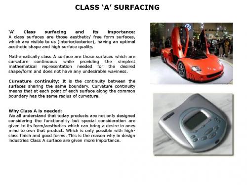
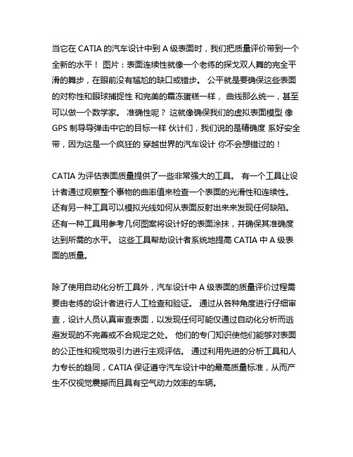
CLASS ‘A’ SURFACING‘A'Class surfacing and its importance:A class surfaces are those aesthetic/free form surfaces,which are visible to us(interior/exterior),having an optimalaesthetic shape and high surface quality.Mathematically class A surface are those surfaces which arecurvature continuous while providing the simplest mathematical representation needed for the desiredshape/form and does not have any undesirable waviness.Curvature continuity:It is the continuity between thesurfaces sharing the same boundary.Curvature continuitymeans that at each point of each surface along the commonboundary has the same radius of curvature.Why Class A is needed:We all understand that today products are not only designed considering the functionality but special consideration aregiven to its form/aesthetics which can bring a desire in onesmind to own that product.Which is only possible with high-class finish and good forms.This is the reason why in designindustries Class A surface are given more importance.UNDERSTANDINGUnderstanding for Class A surfaces:1. The fillets -Generally for Class A, the requirement is curvature continuous and Uniform flow of flow lines from fillet to parent surface value of 0.005 or better (Position 0.001mm and tangency to about 0.016 degrees).2. The flow of the highlight lines -The lines should form a uniform family of lines. Gradually widening or narrowing but in general never pinching in and out.3. The control points should form a very ordered structure -again varying in Angle from one Row to the next in a gradual manner (this will yield the good Highlights required).4. For a Class A model the fillet boundary should be edited and moved to form a Gentle line -and then re-matched into the base surface.5. Matched iso-params in U & V direction are also a good representation of class A.6. The degree (order) of the Bezier fillets should generally be about 6 (also for arc Radius direction) sometimes you may have to go higher.7. Also you have to take care of Draft angle, symmetry, gaps and matching of surfaces Created with parent or reference surfaces.8. Curvature cross-section needles across the part -we make sure the rate of Change of curvature (or the flow of the capping line across the top of the part) is Very gentle and well behaved.The physical meaning:Class A refers to those surfaces, which are CURVATURE continuous to each other at their respective boundaries. Curvature continuity means that at each "point" of each surface along the common boundary has the same radius of curvature.This is different to surfaces having;Tangent continuity -which is directional continuity without radius continuity -like fillets.Point continuity -only touching without directional (tangent) or curvature equivalence.In fact, tangent and point continuity is the entire basis most industries (aerospace, shipbuilding, BIW etc ). For these applications, there is generally no need for curvature.By definition:Class A surface refers to those surfaces which are VISIBLE and abide to the physical meaning, in a product. This classification is primarily used in the automotive and increasingly in consumer goods (toothbrushes, PalmPC's, mobile phones, washing machines, toilet lids etc). It is a requirement where aesthetics has a significant contribution. For this reason the exterior of automobiles are deemed Class-A. BIW is NOT Class-A. The exterior of you sexy toothbrush is Class-A, the interior with ribs and inserts etc is NOT Class-A. QUESTION:What is Body_in_white?What is class A surface?Are the interior trim (A,B,C pillar, dash board, center console, handles) of a car using class A surface? Anybody using the basic design bundle of UG for class A surfacing? UG\Shape Studio?How does it compare with Catia?Ans:1A class A surface is anything that you the customer sees. i.e. exterior panels and interior surfaces.A ClassB surface is something that is not always visible i.e. the underside of a fascia that you would have to bend down to see.A Class C surface is the back side of a part of a surface that is permanently covered by another part.BIW is stuff like the body side etc..Ans:2Actually 'body in white' is the term used to describe the whole vehicle body after it has been welded/bolted together before it is painted or any parts are attached on the fit up line.Ans:3We also use it to mean after it has been painted -I always assumed that the white bit refers to primer. Next step is to fit the windscreen and backlight, when it becomes the glazed body in white, or BIW+G.ANS: 4BIW -Some surfaces are Class A, i.e. body side, roof, sill appliqué.I heard some time ago from a old designer that the term BIW comes from when cars were built from wood, they were painted white as it gives the frame a uniform color so imperfections were easily visible.Ans:5BIW meaning Body In White is so called due to its appearance after the application of the primer to the entirely Body panel assembled vehicle just before going into the painting process.Usually the primer is white or silver grey which gives the so called name.ANS: 6Catia is mostly used for BIW design (Ford switching to catia, and Toyota). Is this because itcould easily create quintic surfaces? With UG with Design bundle only, most of the surfaces created are cubic.-------------------------------------------------------------------ANS: 7A class surface means -it is not just seen surface and unseen surface In normal no technical words,A class surface meansIt is smooth looking reflective surface with no distortion of light highlights, which moves in a smooth uniform designer intended formations.when you create -car body panel, due to their complex shapes it not possible to create the surface with one single face /patch so you make multiple face/patch ( surface is a group of face/patch added together.)when these things are added, at the boundary of joining you need to have connectivity and continuation of minimum order two.for exampleIn case one, at the connecting boundary of two patches you have common boundary but it is sharp corner. this does not qualify as A class surface.In case two -at the connecting boundary of two patches have common boundary and no sharp corner -but you have tangent continuity, this also does not qualify as A class surface.In case two -at the connecting boundary of two patches have common boundary and no sharp corner -you have tangent continuity and curvature continuity this does qualify as A class surface. ( sine curve is good example for curvature continuity. but you can not call it a A class surface )reason is very simple the real requirement of aesthetic and good looking and designer intended shape is not there.ANS:8For obtaining Class-A surfaces,CATIA is more commonly used due to its inherent ability to model very high quality surfaces in general.But,any engineering software(CATIA,UG,IDEAS,Pro-E,etc)cannot develop a Class-A surface.This being due to engineering calculations involved in any surface generated by such softwares.For pure Class-A surfaces you would need styling softwares like Alias,Studio,etc.The use of any software would depend on the level of expectations placed on you.If your projects need only the modeling of the trim,generic engg softwares will do,but if you intend to go down right from styling,you would need Studio,etc.-------------------------------------------------------------------ANS:9IHO,Catia V4has added a tool called Blend surf that is able to obtain virtual curvature continuity.Previously, even styling was comfortable with models-and hence tools-defining fillets with conics,and many OEMs still accept this for Class-A surfaces.Catia V5has GUI interfaces to impose curvature continuity the same way that Alias-Wave front Studio Tools(Auto Studio)does.They are both based on piece-wise polynomial equations,for what its worth.While a conic fillet is not technically curvature continuous,there are many vehicles,including luxury models,that have utilized them for Class-A surfaces and downstream-parts.Considering the tolerances in creating molds and dies and then producing parts from them....a sheet metal panel is not a math model.-------------------------------------------------------------------ANS:10It is true that it is tough to make good curvature continuous surface in UG,but not impossible.Remember one thing A-class doesn't mean just curvature continuity.and smooth reflections on CAD surface.it is lot more than that.Imagine.what happens to your A class surface in case pressed sheet metal body panel. and molded plastic components.They have to retain there intended smoothness and other characteristics to remain A class.to achieve this lot of other things has to be taken care while designing A class surfaces.For example:1-Line features on body side external panel and feature on hood panel which is very common,are to be designed to avoid skidding while they are pressed.like wise2-Flange width and other things are to be taken care while designing fenders wheel arch area for avoiding bulging effect and skidding effect.3-Fuel lid opening area,plunged flange for bulge effect.4-Panel stretching needs to be taken care.Lot many other things go in designing A class sheet metal panels for door,roof etc.5-In case of plastic,sink marks and other things.ANS:11In Europe a'A'class surface is generally taken to be the visible side of any component/assembly-a'B' class surface generally relates to the opposite(or inside)face of an'A'surface-i.e.the surface which defines the thickness of the part,and is where the mounting and reinforcing detail tends to be located.'B' class surfaces can also be referred to as'engineering surfaces.I have not personally heard of any surface being referred to as a'C'type.Catia,while it is ok for surfacing tends to be more used for generating engineering surface detail and solid models-software packages like ICEMSURF tend to be more used for generating visual quality surfaces.-------------------------------------------------------------------ANS:12True A-class surfacing-especially on vehicle exteriors goes further than G2or"curvature"continuity.G3is often sought on the more major block surfaces.G3deals with curvature"acceleration",i.e.the rate of change of curvature across a boundary.G2means as has been described before that the curvature value is the same across a boundary.G3means that the surface curvature leading to the boundary is changing shape at the same rate.Its like driving a car round a bend,you start off straight then gently add steering lock to the point where you need no more,then you gently wind off the steering until you're straight again.If you look at the curve your car made,this would be G3.A-Class and B-class would refer to surface quality required for the component which is different to A-side and B-side which refers to which is the visible/non visible part of a component.ICEM surf is considered the best tool for speedy A-class surfacing due to the sophistication of its real-time diagnostics.The consequence:The consequence of these surfaces apart from visually and physically aesthetic shapes is the way they reflect the real world. What would one expect to see across the boundary of pairs of point continuity, tangent continuity and curvature continuity surfaces when reflecting a straight and dry tree stump in the desert????Point Continuity (also known as G0 continuity) -will produce a reflection on one surface, then at the boundary disappear and re-appear at a location slightly different on the other surface. The same reflective phenomenon will show when there is a gap between the surfaces (the line markers on a road reflecting across the gap between the doors of a car).Tangent Continuity (also known as G1 continuity) -will produce a reflection on one surface, then at the boundary have a kink and continue. Unlike Point continuity the reflection (repeat REFLECTION) is continuous but has a tangent discontinuity in it. In analogy, it is "like" a greater than symbol.Curvature Continuity (also known as G2 continuity, Alias can do G3!) -this will produce the unbroken and smooth reflection across the boundary.To achieve the same Class 'A' surfaces that automotive manufacturers demand, consumer product manufacturers have availed themselves of the same advanced surface modeling tools. What is a Class 'A' surface? The simple answer is that it is a perfectly smooth surface with no anomalies, in which all adjoining surfaces have curvature continuity. This means that where two surfaces meet, the graduation of one into the other is achieved without discernible abrupt transitions. The techniques used to create Class 'A' surfaces typically reside in top level surface modeling software developed for the motor industry, rather than mid-range mechanical CAD packages that have evolved from 3D solid modeling for mechanical assemblies.Analyzing A Class SurfaceHighlight plot :Highlight is the behavior of the form orShape of a surface when a light ornature reflects on it. This reflection oflight or nature gives you anunderstanding about the quality ofsurface. This reflection required shouldbe natural, streamline and withuniformityDesigner Fillets:If you take two adjoining2D lines,or a couple of tangential surfaces,the intersection between them can be turned into an arc(2D)or a fillet(3D),each of which is inserted with a constant radius.However the transition from each line or surface can often be too abrupt for the design.According to Mike Lang,Technical Director of VX,fillets should look simple-you shouldn't see a fillet line in a model.They should also be simple to create."Achieving tangent and curvature continuity in complex shapes on other systems is hard work.A reduction in the weight of a curve will allow it to retain its tangency,but sharpen the change in curvature. This can be seen most effectively by reducing the weight almost to zero.Fairings-the shape of the curve-can be influenced by energy,variation,jerk,bend or tension-each of which will produce a subtle difference in the mathematical fit through the curve.Echo Attributes:Part of the process of obtaining Class'A'surfaces is being able to see what's happening to the curve or the surface as it is being developed.Increasing the scale of the iso lines allows designers to pick up smaller imperfections in surfaces.Where blue iso lines lose their curve they change to white.The shifting colors of Gaussian shading are also particularly adept at detecting subtle blemishes.Echo Attributes also has numerous other modifiable elements,including the ability to apply colors to lines and surfaces,and to alter the transparency of the surface.Curvature plots on non-designer fillets show regular arcs,unlike designer fillets that show the weighting of the curve at each point."good design work relies on good wire frame technology.If you don't have basic curve geometry,you won't be able to produce a good surface”.Designers must always go through the routine of checking curves,especially if the design has come in from an outside source-perhaps containing older style Bezier curves with lots of points.The following describes the mathematics for the so called Bezier curve.It is attributed and named after a French engineer ,Pierre Bezier ,who used them for the body design of the Renault car in the 1970's.They have since obtained dominance in the typesetting industry.Consider N+1control points pk (k=0to N)in 3space.The Bezier parametric curve function is of the form.B (u)is a continuous function in 3space defining the curve with N discrete control points P k .u=0at the first control point (k=0)and u=1at the last control point (k=N).Notes:•The curve in general does not pass through any of the control points except the first and last. From the formula B (0) = P 0and B (1) = P N .•The curve is always contained within the convex hull of the control points, it never oscillates wildly away from the control points.•If there is only one control point P 0, i.e.: N=0 then B (u) = P 0for all u.•If there are only two control points P 0and P 1, i.e.: N=1 then the formula reduces to a line segment between the two control points.•the term shown below is called a blending function since it blends the control points to form the Bezier curve.Bezier Curves•The blending function is always a polynomial one degree less than the number of control points. Thus 3 control points results in a parabola, 4 control points a cubic curve etc.•Closed curves can be generated by making the last control point the same as the first control point. First order continuity can be achieved by ensuring the tangent between the first two points and the last two points are the same.•Adding multiple control points at a single position in space will add more weight to that point "pulling" the Bezier curve towards it.•As the number of control points increases it is necessary to have higher order polynomials and possibly higher factorials. It is common therefore to piece together small sections of Bezier curves to form a longer curve. This also helps control local conditions, normally changing the position of one control point will affect the whole curve. Of course since the curve starts and ends at the first and last control point it is easy to physically match the sections. It is also possible to match the first derivative since the tangent at the ends is along the line between the two points at the end.Second order continuity is generally not possible.•Except for the redundant cases of 2 control points (straight line), it is generally not possible to derive a Bezier curve that is parallel to another Bezier curve.A circle cannot be exactly represented with a Bezier curve.It isn't possible to create a Bezier curve that is parallel to another,except in the trivial cases of coincident parallel curves or straight line Bezier curves.Bezier curves have wide applications because they are easy to compute and very stable. There are similar formulations which are alsocalled Bezier curves which behave differently, in particular it ispossible to create a similar curve except that it passes through the control points. See also Spline curves.Examples: The pink lines show the control point polygon, the grey lines the Bezier curve.1.The degree of the curve is one less than the number of controlpoints, so it is a quadratic for 3 control points. It will always besymmetric for a symmetric control point arrangement.2.The curve always passes through the end points and is tangent tothe line between the last two and first two control points. Thispermits ready piecing of multiple Bezier curves together with first order continuity.3.The curve always lies within the convex hull of the control points.Thus the curve is always "well behaved" and does not oscillatingerratically.4.Closed curves are generated by specifying the first point the sameas the last point. If the tangents at the first and last points match then the curve will be closed with first order continuity.. Inaddition, the curve may be pulled towards a control point byspecifying it multiple times. 1 2 3 4The Bezier surface is formed as the Cartesian product of the blending functions of two orthogonal Bezier curves.Where P i,j is the i,jth control point. There are N i+1and N j+1control points in the i and j directions respectively. The corresponding properties of the Bezier curve apply to the Bezier surface. -The surface does not in general pass through the control points except for the corners of the control point grid. -The surface is contained within the convex hull of the control points. Along the edges of the grid patch the Bezier surface matches that of a Bezier curve through the control points along that edge.Closed surfaces can be formed by setting the last control point equal to the first. If the tangents also match between the first two and last two control points then the closed surface will have first order continuity. While a cylinder/cone can be formed from a Beziersurface, it is not possible to form a sphere.BEZIER SURFACEA little history of Surface Modeling A little historySurface modeling was developed in the automotive and aerospace industries in the late1970s to design and manufacture complex shapes.Nurbs--nonuniform rational B-splines--and cubic-surface formats appeared early and remain the primary spline and surface formatsused throughout the CAD industry.Nurbs and cubics are supported byIGES(Initial Graphics Exchange Specification),a neutral file format for exchanging data between CAD systems.Nurbs and cubic formats are represented in a computer by polynomial equations generated by a CAD system,and onscreen through thelocation and shape of curves and surfaces.For example,the equationof a line,a first-degree polynomial,has this formY=ax+bThe equation for a parabola,a second-degree polynomial,has the formY=ax2+bx+cAnd the equation of a cubic spline,a third-degree polynomial,looks likeY=ax3+bx2+cx+dThe more terms in the polynomial equation,the more"shape"thecurve or surface has.The data structure of a Nurbs curve or surface is comprised of points, weights,and parameter values that define a control net which istangent to the curve or surface.The control net on a Nurbs surface is a rectangular grid of connected straight-line elements which define thetangency of the surface at positions along the control net.The points inthe database which describe the control net are not actually on the surface,they are at the vertices of the control net.Weights in theNurbs data structure determine the amount of surface deflectiontoward or away from its control point.Cubic data structures use third-degree polynomials that describe pointsactually on the curve or surface.Therefore,the Nurbs control net is an abstraction of the underlying surface,whereas the cubic equation is the surface.Nurbs and cubic formats each have advantages and disadvantages.Nurbs equations model more complex shapes by increasing the degree of the exponents in the polynomial,thus increasing the memory required to store and evaluate the equation.Cubic equations,on the other hand,require less storage and can capture complex shapes by adding more cubic segments to the spline or surface.Nurbs and cubic equations are said to be"piecewise"and"parametric,"which means the curve or surface is a sequence of connected segments that use parametric u and v values ranging from0to1or0to n(number of segments)to calculate points along the curve or surface.Nurbs and cubic formats each have advantages and disadvantages.Nurbs equations model more complex shapes by increasing the degree of the exponents in the polynomial,thus increasing the memory required to store and evaluate the equation.Cubic equations,on the other hand,require less storage and can capture complex shapes by adding more cubic segments to the spline or surface.Nurbs and cubic equations are said to be"piecewise"and"parametric,"which means the curve or surface is a sequence of connected segments that use parametric u and v values ranging from0to1or0to n(number of segments)to calculate points along the curve or surface.Ultimately,a good CAD system shields users from having to know too much about the mathematics that represent the underlying surfaces.In addition,surface modelers should:Provide enough tools to completely define any feature on the part using surfaces.Have many functions for defining the different shapes of surfaces including ruled,revolved,lofted,extruded, swept,offset,filleted,blended,planar boundary,and drafted.Each of these functions have further variations. For example,offset surfaces should allow for constant or tapered offsets.Draft-surface functions should let users input curves to define the draft surface,or allow using curves on a surface whereby the draft angle is referenced off a surface-normal vector at points along the curve.The lofted surface should allow for the input of cross-section curves or for the input of curves both along and across the surface.Support functions such as surface trimming,extending,intersecting,projecting,polygon tessellation,IGES translation,coordinate-system transformations,and editing.Allow extracting surface data such as flow curves,vectors,and planes,among other functions.Have a set of tools for defining points,planes,vectors,and splines used with surface modeling.Most surface creation functions need user inputs to define surfaces.Two useful surface-modeling functions are the controlled sweep and the draft surface.A controlled sweep forces a profile curve to remain perpendicular to the sweep path by using a control surface.Without a control surface in the construction of a swept surface,the profile curve typically wants to lay down or spin around the sweep path.A properly defined control surface solves the problem.A draft surface is similar to a controlled sweep in that it uses curves lying on one surface to create another.The resultant draft surface passes through the input curve and is composed of straight-line elements radiating from the reference surface at an angle to the surface normal vectors taken at points along the input curve.A draft-surface function can build one surface perpendicular to another,along a curve.A Comparison Between Solid-Surface Modeling:While surface modelers excel at defining complex shapes,solid modeling is good at quickly building primitive geometry.Primitive geometry consists of basic surfaces such as planes,cylinders,cones, spheres,and tori.Surface modeling is not as fast at creating simple part geometry,but if your solid modeler can't easily model a feature,such as a fillet,surface modeling can almost always finish the part. And for every solid-modeling function there is a counterpart in surface modeling.Nurbs surfaces can be incorporated into an existing solid model by"stitching"the Nurbs surface to the solid model.Some parts can be completely defined by a solid modeler as a collection of primitive surfaces,while other parts require Nurbs surfaces to fully define the geometry.Most parts manufactured with tooling require some kind of Nurbs surface to support production.Reverse engineering is heavily dependent on Nurbs surfaces to capture digitized points into surfaces.In addition,Nurbs-surface files generated over the last20years are circulating in IGES format between vendors and subcontractors.These files support the design of parts in one system and manufacturing in another.Solid modeling will not replace Nurbs-surface modeling because the two work hand in hand to complete part geometry.TYPES OF CONTINUTYContinuity is a measure of how well two curves or surfaces "flow" into each other.•POSITION (G0)This type of continuity between curves implies that the endpoints of the curves have the same X,Y, and Z position in the world space. This is the minimum requirement for obtaining G0.•TANGENT (G1)This type of continuity between curves implies that the tangent CVs must be on one line.•CURVATURE (G2)This continuity type impacts the third CV of the curve. All three CVs have to be considered in order to maintain a smooth curvature comb.If a curvature comb does not have a smooth transitional line. In order to improve the curvature comb, manually modify the position of the three CVs that constitute the G2continuity.。
CATIA CATIAA级曲面检查规范说明

重庆南方摩托车技术研发有限公司CATIA A 级曲面检查规范北京迅利创成科技有限公司日期:2011年12月7日目录1.规范描述............................... 错误!未定义书签。
级曲面介绍............................... 错误!未定义书签。
定义................................. 错误!未定义书签。
特征................................. 错误!未定义书签。
级曲面标准............................... 错误!未定义书签。
设置建模精度......................... 错误!未定义书签。
曲面间的间隙/重叠.................... 错误!未定义书签。
曲面间的连续性....................... 错误!未定义书签。
光顺性要求........................... 错误!未定义书签。
脱模................................. 错误!未定义书签。
配合间隙............................. 错误!未定义书签。
输出格式............................. 错误!未定义书签。
4规范内容 ............................... 错误!未定义书签。
高光连续性检查....................... 错误!未定义书签。
连续性检查.......................... 错误!未定义书签。
曲率梳连续性检查..................... 错误!未定义书签。
两零件搭接关系检查................... 错误!未定义书签。
A级曲面的间距离检查................. 错误!未定义书签。
2024版全新catia官方培训

其他领域应用实例
工业设计
CATIA可用于各种工业产品的设计,如家电、家具等,实现产品的 创新设计和快速原型制作。
建筑设计
利用CATIA进行建筑的三维建模和设计,提高建筑设计的质量和效 率。
机器人设计
通过CATIA进行机器人的三维建模和运动仿真,优化机器人结构和控 制算法。
CHAPTER 05
catia与其他CAD软件的比较 与集成
catia与UG的比较
01
曲面造型
catia在曲面造型方面功能强大,支持高级曲面设计和分析工具,而UG
在曲面造型方面也具有相似的功能。
02
钣金设计
catia提供了专业的钣金设计工具,支持钣金件的展开和折叠等操作,
而UG的钣金设计功能相对较弱。
03
定制化与二次开发
catia支持高度的定制化和二次开发,用户可以根据自己的需求进行定
CHAPTER 06
培训总结与展望
培训成果回顾
掌握了catia软件的基本操作和技能
通过本次培训,学员们熟练掌握了catia软件的基本操作和技能,包括建模、装配、工程图等 方面的知识。
完成了多个实践项目
在培训过程中,学员们通过完成多个实践项目,深入了解了catia软件在实际工作中的应用, 积累了宝贵的实践经验。
catia具有强大的建模、分析和 优化功能,支持多领域协同设 计和仿真
catia软件界面友好,操作便捷, 可大幅提高设计效率和质量
培训目标与内容
培训目标
使学员熟练掌握catia软件的基本操 作和高级功能,能够独立完成复杂 产品的设计和分析任务
培训内容
包括catia软件安装与配置、基础操 作、高级建模、装配设计、工程图 制作、钣金设计、模具设计、数控 编程等
catia的汽车a级曲面质量评价方法
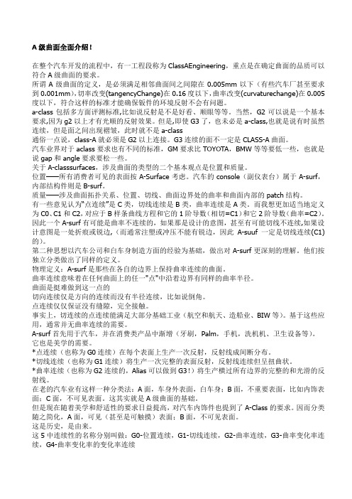
当它在CATIA的汽车设计中到A级表面时,我们把质量评价带到一个全新的水平!图片:表面连续性就像一个老练的探戈双人舞的完全平滑的舞步,在眼前没有尴尬的缺口或错步。
公平就是要确保这些表面的对称性和眼球捕捉性和完美的霜冻蛋糕一样,曲线那么统一,甚至可以做一个数学家。
准确性呢?这就像确保我们的虚拟表面模型像GPS制导导弹击中它的目标一样伙计们,我们说的是精确度系好安全带,因为这是一个疯狂的穿越世界的汽车设计你不会想错过的!
CATIA为评估表面质量提供了一些非常强大的工具。
有一个工具让设计者通过观察整个事物的曲率值来检查一个表面的光滑性和连续性。
还有另一种工具可以模拟光线如何从表面反射出来来发现任何缺陷。
还有一种工具用参考几何图案将设计好的表面涂抹,并确保其准确度达到所需的水平。
这些工具帮助设计者系统地提高CATIA中A级表面的质量。
除了使用自动化分析工具外,汽车设计中A级表面的质量评价过程需要由老练的设计者进行人工检查和验证。
通过从各种角度进行仔细审查,设计人员认真审查表面,以发现任何可能仅通过自动化分析而逃避发现的不完善或不合规定之处。
他们的专门知识使他们能够对表面的公正性和视觉吸引力进行主观评估。
通过利用先进的分析工具和人力专长的趋同,CATIA保证遵守汽车设计中的最高质量标准,从而产生不仅视觉震撼而且具有空气动力效率的车辆。
04-CATIA (汽车摩托车企业-设计人员内部培训资料)重庆南方摩托车DMU数字样车干涉检查规范及方法论-V02

1.干涉检查的目的及意义3. 干涉检查有目的性,便于应用。
4. 对于已应用的干涉可以进行快速的查找。
DMU 审查创建工具条下的审查命令。
创建一个审查文件包,用来存放需要检查的各个子总成。
由于每个干涉结果只能在指定的审查文件包中存放,固该文件包需要针对与每个需要检查的总成单独创建。
分别用来存放每个单独总成下子总成的组。
且最终审查文件包的级次与CATIA结构树的级次一一对应,这样便于干涉检查的结果的保存和查找。
在审查文件包创建完成后,在结构树中双击文件夹,即可激活该审查文查文件包下。
Step.3 创建各个一级总成所对应的组。
确认无误后点击确定。
在结构树中生成一个组。
并通过属性修改其名称为:51000000-MQ05010-0.1,使之与结构树中一级总成名称唯依照此方法,创建所有一级总成的组。
并在属性中对其进名称这样,就完成了整个样机的一级总成数据组织。
今后在应用的时,只需要点击组即可完成每个单独总成的选取。
便于操作。
各系统中数据的组织在完成了整车数据组织之后,为了将各个系统的检查结果表述清晰,需要继续创建各系统的审查文件包及系统内子总成的组。
实施步骤如下:Step.1 先通过鼠标右键在级审查文件包的扩展菜单中关闭该文件包。
这样,就可以跳出该文件包,在点击创建审查文件包命令在结构树根目录下创建新的审查文件包,并命名为一级总成名称。
用来存放该总成下子总成的组。
Step.3 创建一级总成下子总成的组。
并将其放置在该一级总成的审查文件包下。
Step.4 依次创建所有一级总成所对应的审查文件包及其内部子总成所对应的组。
这样,就完成了第一版数据整机数据的组织。
其组织形式与BOM级次相对应,能够快速的实现零件查找及应用。
为后期的干涉检查做好的准备,也使得干涉检查能够快速系统的完成。
2.3 更新数据组织对于第一版数据以后的数据,进行后期更新数据组织。
由于后期数据更新是及时的更新,即以没有完整的样车数据。
这样,就无需在进行整机的数据组织,只要完成更新零件,及更新零件周边零件的数据组织即可。
汽车设计-A级曲面(A-Class Surface)模型设计质量规范模板
XX公司企业规范编号xxxx-xxxx汽车设计-A级曲面(A-Class Surface)模型设计质量规范模板A级曲面模型设计质量规范1 范围本规范规定了使用计算机软件(Alias或CATIA V5)构建A-Class Surface曲面数字模型所遵循的质量技术要求。
2 术语和定义下列术语和定义适用于本规范。
曲面Surface数学点的集合,它是在平面(R2)的一个连通子集上定义的连续函数图像。
A级曲面A-Class Surface造型外表面数字模型的一种,满足特定的技术质量要求,用于表示最终冻结的造型外表面。
曲面连续性Surface Continuity在使用多个小块曲面构建大的曲面时,在两个和两个以上曲面进行拼接边界处存在的几何位置关系。
一般用到的有位置连续(G0)、相切连续(G1)、曲率连续(G2)、曲率变化率连续(G3)。
曲线阶数曲线数学表达多项式的最高次幂就是曲线的阶数(Degree),等于该曲线控制点数(Order)减一。
曲线控制点(CV)与控制边(Hull)曲线的直观表达一般用控制点来表示的,两个相邻控制点的连线就是控制边(Hull)。
如图1所示。
曲线Span用来描述曲线特定位置分段数字信息,可以简单的理解为曲线的段。
曲线可以是单段(1 Span)多次的,也可以是多段(N Spans)多次的。
如图1所示,图1中的曲线就是多段(N Spans)多次。
图1 曲线基本信息图曲面块Patch在使用曲线构建曲面过程中,形成曲面的U、V方向上曲线的Span数的乘积就是曲面的Patch数,也相应把曲面分成若干个曲面块(Patch)。
如图2所示。
图2 曲面基本信息图3 A-Class Surface曲面数字模型质量要求3.1公差要求3.1.1曲线间隙:=0mm。
3.1.2曲面间隙:≤0.003mm;3.1.3曲面相切角度偏差:≤0.1Grad(圆角处:≤0.5Grad)。
3.1.4没有边长小于1mm的微小曲面。
CATIA汽车摩托车企业设计人员内部培训CATI级曲面检查规范说明OK

重庆南方摩托车技术研发有限公司CATIAA级曲面检查规范北京迅利创成科技有限公司日期:2011年12月7日目录1.规范描述 (1)2.A级曲面介绍 (2)2.1定义 (2)2.2特征 (2)3.A级曲面标准 (3)3.1设置建模精度 (3)3.2曲面间的间隙/重叠 (3)3.3曲面间的连续性 (3)3.4光顺性要求 (4)3.5脱模 (4)3.6配合间隙 (4)3.7输出格式 (4)4规范内容 (5)4.1高光连续性检查 (5)4.2 连续性检查 (7)4.3曲率梳连续性检查 (7)4.4两零件搭接关系检查 (8)4.5 A级曲面的间距离检查 (8)4.6 曲面“阶”数检 (9)1.规范描述A级曲面检查是为了规范使用CATIA对外委数模和本公司设计的高质量模型表面的检查,检查的目的是检验模型的质量是否符合A级曲面的标准、要求。
本规范对A级曲面检查的标准进行了初步的定义,并对采用CATIA V5进行A级曲面检查的具体功能和操作进行了详细的说明。
2.1定义A级曲面是那些在各自的边界上保持曲率连续的曲面,曲率连续意味着在任何曲面上的任一“点”中沿着边界有同样的曲率半径。
A级曲面广泛应用于汽车行业的外观件和内饰件。
同样的,针对摩托车行业,所有的摩托车覆盖件原则上都应当遵循A级曲面的质量要求。
摩托车覆盖件A面造型汽车车身外表面A 面造型2.2特征同一般的零件结构曲面不同,A级曲面通常具有如下的一些特征:一般CLASS A的阶次与控制点数目都不多,一般曲面UV方向大概为6个控制点;单独一个CLASS A曲面在UV方向都保证曲率的连续性及变化趋势的一致;CLASS A曲面之间的连接需要满足曲率连续(G2),在部分特殊曲面可以用切连续来保证(G1),绝对禁止仅仅是点连续(G0);使用多种数学检验方法来检验CLASS A曲面,不应该出现视觉上的明显瑕疵。
3.1设置建模精度覆盖件建模精度的要求标准为0.005mm,即当覆盖件精度值大于0.005mm时,不满足我们的A级曲面建模的标准,只有当覆盖件建模精度值小于或等于0.005mm时,才满足A级曲面的建模要求。
CATIA A级曲面全面介绍
A级曲面全面介绍!在整个汽车开发的流程中,有一工程段称为ClassAEngineering,重点是在确定曲面的品质可以符合A级曲面的要求。
所谓A级曲面的定义,是必须满足相邻曲面间之间隙在0.005mm以下(有些汽车厂甚至要求到0.001mm),切率改变(tangencyChange)在0.16度以下,曲率改变(curvaturechange)在0.005度以下,符合这样的标准才能确保钣件的环境反射不会有问题。
a-class包括多方面评测标准,比如说反射是不是好看、顺眼等等。
当然,G2可以说是一个基本要求,因为g2以上才有光顺的反射效果。
但是,即使G3了,也未必是a-class,也就是说有时虽然连续,但是面之间出现褶皱,此时就不是a-class通俗一点说,class-A就必须是G2以上连接。
G3连续的面不一定是CLASS-A曲面。
汽车业界对于aclass要求也有不同的标准,GM要求比TOYOTA,BMW等等要低一些,也就是说gap和angle要求要松一些。
关于A-classsurfaces,涉及曲面的类型的二个基本观点是位置和质量。
位置——所有消费者可见的表面按A-Surface考虑。
汽车的console(副仪表台)属于A-surf,内部结构件则是B-surf。
质量——涉及曲面拓扑关系、位置、切线、曲面边界处的曲率和曲面内部的patch结构。
有一些意见认为“点连续”是C类,切线连续是B类,曲率连续是A类。
而我想更加适当地定义为C0、C1和C2,对应于B样条曲线方程和它的1阶导数(相切=C1)和它2阶导数(曲率=C2)。
因此一个A-surf有可能是曲率不连续的,如果那是设计的意图,甚至有可能切线不连续,如果设计意图是一处折痕或锐边,(而通常注塑或冲压不能有锐边,因此A-suuf一定是切线连续(C1)的)。
第二种思想以汽车公司和白车身制造方面的经验为基础,做出对A-surf更深刻的理解。
他们按独立分类做出了同样的定义。
20-CATIA(汽车摩托车企业-设计人员内部培训资料)基于C
2020/2/23
© RP-TECH 2011
25
Powercopy的定义
Powercopy是一组表达产品典型结构特征的、可以重复使用的特征集,是 一个预先制作的复制工具
在使用的时候,用户必须预先指定输入元素 在其他零件的设计中可以直接制定和插入PowerCopy Powercopy工具条在以下工作模块的Insert目录下: Part design GSD SheetMetal Design
2020/2/23
© RP-TECH 2011
229
零件的创建
完成零件设计特征
零件模板指定文档 输入项控制
参数发布 属性设置
2020/2/23
© RP-TECH 2011
330
零件模板的应用
注意: 零件模板应用于装配层面。 输入的定位元素最好是无参的(与调入时相配置),一般是定位点,定位平 面,方向。 生成零件模板之后要保存。 参数尽量越少越好,尽量能够一个参数控制多个特征。 参数的命名也要直观,使其他人使用的时候能够清楚的知道此参数的意义。
2020/2/23
© RP-TECH 2011
5
参数—定义
参数的类型:实数;长度;角度;体积;线……
实型(无单位) a=30 b=40 长型(单位: mm) c=50mm R=60mm 时间(单位:s) t=35s,40s,60s 面积(单位:mm2) S=20mm2,30mm2,40mm2
参数值有两种形式:
2020/2/23
© RP-TECH 2011
15
公式—创建
可以在公式编辑器中使用 CATIA提供的相关函数:如 距离测量。
2020/2/23
© RP-TECH 2011
CATIA中A级曲面应用全面介绍精华篇
A级曲面没有十分严格的数学描述也没有十分严格的概念定义。
在汽车行业,所谓A级曲面的定义,是必须满足相邻曲面间的间隙在 0.005mm 以下(有些汽车厂甚至要求到 0.001mm),切率改变 ( Tangency Change ) 在0.16度以下,曲率改变 (Curvature Change) 在0.005 度以下,符合这样的标准才能确保钣件的环境反射不会有问题。
CLASS-A包括多方面评测标准,比如说反射是不是好看、顺眼等等。
当然,G2可以说是一个基本要求,因为G2以上才有光顺的反射效果。
但是,即使G3了,也未必是A级曲面,也就是说有时虽然连续,但是面之间出现褶皱,此时就不是A级曲面了。
通俗一点说,CLASS-A就必须是G2以上连接。
汽车业界对于A级曲面要求也有不同的标准,GM要求比TOYOTA ,BMW等要低一些,也就是说Gap和Angle要求要松一些。
关于A级曲面,涉及曲面类型的二个基本观点是位置和质量。
位置,所有消费者可见的表面按A-Surf考虑,汽车的Console(副仪表台)属于A-Surf,内部结构件则是B-surf;质量,涉及曲面拓扑关系、位置、切线、曲面边界处的曲率和曲面内部的Patch结构。
在老的汽车业有这样一种分类法:A面,车身外表面,白车身;B面,不重要表面,比如内饰表面;C面,不可见表面。
这其实就是A级曲面的基础。
但是现在随着美学和舒适性的要求曰益提高,对汽车内饰件也提到了A-CLASS的要求。
因而分类随之简化,A面,可见(甚至是可触摸)表面;B面,不可见表面。
关于曲面质量的连续理论,有一些意见认为“点连续”是C类,切线连续是B类,曲率连续是A类。
而我想更加适当地定义为C0、C1和C2,对应于B样条曲线方程和它的1阶导数(相切=C1)和它2阶导数(曲率=C2)。
因此一个A-surf有可能是曲率不连续的,如果那是设计的意图,甚至有可能切线不连续,例如设计意图是一处折痕或锐边。
CATIA软件培训教程(内部资料)

谢 谢!
24�Biblioteka 11CATIA简介
在CATIA V5的开发过程中应用了许多先进的技术,例 如:C++语言,面向对象的设计思想,基于JAVA和Web的技 术,STEP-SDAI, OpenGL, OLE/CorbRa, Visual Basic 等. CATIA V5是新一代全新设计的软件,运行的硬件平台 独立,即可运行于UNIX也可以运行于Windows NT.它适合 于各种规模的企业,支持电子化企业的解决方案,可以将 隐式的设计实践转化为嵌入整个设计过程的显式的知识. 对于原有客户可以平滑的过渡到V5版本. CATIA与NT紧密联系,与NT的组件Office可以很容易 地 实 现 互 操 作 , 熟 悉 Office 的 用 户 可 以 很 容 易 的 接 受 CATIA的的工作界面.很多操作,例如拖拽,粘帖等操作 完全一样.CATIA V5是基于图形化的界面,易学易用.
CATIA软件培训 软件培训
周红波
2010-7-13
1
本章节主要内容:
CATIA软件简介 CATIA软件的应用 培训课程安排
2
CATIA软件简介 CATIA软件的应用 培训课程安排
3
CATIA
有哪些功能?
4
5
6
7
8
9
10
CATIA简介
CATIA V5是IBM/DS基于Windows NT/2000操作系 统上开发的高端的CAD/CAM软件,它涵盖了产品开发 的全过程,提供了完善无缝的集成环境. CATIA V5之前的版本CATIA V4是基于UNIX系统开 发的,随着NT操作系统的普及,以及个人计算机性能 不断地提高,成本不断地下降,许多高端的CAD/CAM 软件纷纷从UNIX移植到Windows NT平台.IBM/DS在充 分了解客户的需求,并积累了大量客户的应用经验后, 决定开发新一代基于NT平台的CATIA即CATIA V5.
CATIA-轿车外形A级曲面设计
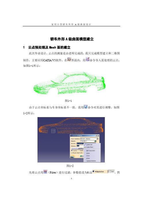
家用小型轿车外形A 级曲面设计1轿车外形A 级曲面模型建立1 云点预处理及Mesh 面的建立此次毕业设计,云点的测量是由老师完成的,我只完成模型建立和二维图制作,主要应用CATIA V5软件,在界面内,用命令导入需处理的云点,如图1-1所示:图1-1 由于云点坐标系与车身坐标系不一致,需用命令对其进行调整,如图1-2所示:图1-2 先将云点用(Filter )进行过滤,参数值设为0.11。
然家用小型轿车外形A 级曲面设计2 后对云点用命令,生成Mesh 面,如图1-3所示:图1-32 顶盖、发动机罩及行李箱盖A 级曲面设计由于整车是一个对称体,所以只需做一半的车身曲面,另一半靠对称完成。
我们在做中间曲面时,就必须保证这些曲面关于ZX 平面对称后两块曲面之间无缝、无重叠,无棱角,并且具有较好的光顺性。
因此,在做顶盖、发动机罩及行李箱盖曲面时,就需注意上述要求,下面介绍两种常用的方法:1 由云点生成线,再由线组成一封闭体,在界面,用命令生成面。
这样作出的曲面比较容易保证光顺性,但此曲面与云点的误差较大,所以这就要求画出的线与云点所在的面结合很好。
2 由云点生成线,再由线组成一封闭体,在界面,用命令截取封闭体内的部分云点,再用命令生成面。
这样作出的曲面与云点的误差较小,但曲面的光顺性不易保证。
这就要求用命令生成面时,结合系数不能选的太小。
下面我将用上述两种方法完成顶盖、发动机罩及行李箱盖A 级曲面的制作。
2.1 应用第一种方法完成顶盖A 级曲面设计 首先,在界面,用命令,在ZX 平面上截出一组此平面上的点,如图2-1所示。
在图中看出由ZX 平面截出的是一条线,其实它是由很多的点组成,家用小型轿车外形A 级曲面设计3 并不是线,我们可通过(Cloud Display Options )命令将这些点稀释,就可看清这条“线”其实是点,如图2-2所示。
图2-1图2-2 用(3D Curve )画出一条光顺曲线,如图2-3所示:家用小型轿车外形A 级曲面设计4图2-3 通过(Curvature Analysis )分析曲线的光顺性,如图2-4所示。
14-CATIA(汽车摩托车企业-设计人员内部培训资料)基于C
© RP-TECH 2011
25
上下文背景设计的定义(1/2) Context是指上下文设计的零件所处的装配产品。即如果打开该产品,将显 示所有的具有Context关联子零件所对应的父元素,并解析所有的关联。 在一个装配件中可包含CATParts、CATProduct、V4模型以及其它的外部 模型(IGES、STEP等),这些之间模型之间通过装配约束来进行定位; 在CATProduct文档中,可以在几个零件之间创建ssociative Links,这些 Links可以是“外部几何参考”,也可以是“外部参数参考”; 如果一个零部件通过“外部几何参考”或者“外部参数参考”进行创建,这就是 上下文背景设计。
2020/7/20
© RP-TECH 2011
21
几何特征的发布(1/2) 下面是几何特征发布的步骤: 1.激活包含要发布几何特征的零件; 2.点击Tools>Publications; 3.选择要发布的几何特征; 4.所选择的几何特征添加到Publications窗口;
2020/7/20
© RP-TECH 2011
2020/7/20
© RP-TECH 2011
17
Publication 机制介绍
如果一个用户创建的几何特征需要被其他不同用户的 几何特征所引用,这时就需要通过Publication机制将 需要被引用的特征发布,使之在整个工作域内用户所 见;
在关联设计中,发布几何特征和参数是为了帮助用户 更好的控制所创建的外部参考特征;
2020/7/20
© RP-TECH 2011
如果一个产品替换另外一个产品,则所有的约束就会被打破。而使用
Publications会避免出现这种情况。
2020/7/20
a 面技术和检验标准

a 面技术和检验标准奇瑞汽车有限公司企业标准车身外形曲面Class A 标准(试行)1、范围。
车身外形曲面Class A的一些基本的质量和检验要求。
2、引用标准。
无3、术语。
3.1 A Class曲面: 达到G2, G3连续,即2阶或3阶连续。
面与面之间曲率连续。
3.2 B Class曲面:达到G1连续,即1阶连续。
面与面之间相切连续;曲率不连续;点连续;3.3 C Class曲面:达到G0连续,即0阶连续。
面与面之间点连续;曲率不连续,相切不连续。
4、技术要求:面的质量要求最终是精细的光学质量要求,以达到良好的视觉效果。
用户可以在丰富的灯光条件下获得好的外表效果,这就说明这个数据模型是高质量的。
为了达到这个目的通常使用一些灯光来检查面的连续性和表面的张力。
在曲率曲率不连续;B-CA-CCATIA软件中有一些检测的方法如:斑马线,反射线等都可以作为数据检测的方法。
5、数据质量要求:5.1 面的分块:5.1.1 面应该具有一定的造型效果。
5.1.2 面的分块应该将主模型作为一个整体来考虑,而不是由一些小块组合起来变成整体。
被分块的面以面的边界为边界,整体的思想可保证整个面的和谐统一。
建议采用尽可能少的面片,面片采用贝齐尔(BEZIER)曲面,曲面使用单段面和低阶面。
不要采用非均匀有理样条(NURBS)曲面。
NURBS曲面BEZIER曲面5.1.3 为了指导正确的完成数据,要避免下面的情况:5.1.3.1 在属于模型的元素之间不合理的分块5.1.3.2 出现重面;5.1.3.3 存在一些不属于模型的元素,不能被剪切;5.1.3.4 存在三角面和单独的面;5.1.3.5 过多的使用了延伸面或是超出边界过多;5.1.3.6 偶然出现面的参数不能调整;5.1.3.7 面的边界线对应面的轮廓线5.2 半径和过渡面。
用数字化方法创建过渡面时,尽可能避免在一些过渡面上使用出现呆板的曲率变化或是定曲率的方式,这些呆板的面仅限于在一些不重要的或是不显眼的地方。
- 1、下载文档前请自行甄别文档内容的完整性,平台不提供额外的编辑、内容补充、找答案等附加服务。
- 2、"仅部分预览"的文档,不可在线预览部分如存在完整性等问题,可反馈申请退款(可完整预览的文档不适用该条件!)。
- 3、如文档侵犯您的权益,请联系客服反馈,我们会尽快为您处理(人工客服工作时间:9:00-18:30)。
重庆南方摩托车技术研发有限公司CATIA A级曲面检查规范
北京迅利创成科技有限公司
日期:2011年12月7日
目录
1.规范描述 (1)
2.A级曲面介绍 (2)
2.1定义 (2)
2.2特征 (2)
3.A级曲面标准 (3)
3.1设置建模精度 (3)
3.2曲面间的间隙/重叠 (3)
3.3曲面间的连续性 (3)
3.4光顺性要求 (4)
3.5脱模 (4)
3.6配合间隙 (4)
3.7输出格式 (4)
4规范内容 (5)
4.1高光连续性检查 (5)
4.2 连续性检查 (9)
4.3曲率梳连续性检查 (10)
4.4两零件搭接关系检查 (12)
4.5 A级曲面的间距离检查 (12)
4.6 曲面“阶”数检 (13)
1.规范描述
A级曲面检查是为了规范使用CATIA对外委数模和本公司设计的高质量模型表面的检查,检查的目的是检验模型的质量是否符合A级曲面的标准、要求。
本规范对A级曲面检查的标准进行了初步的定义,并对采用CATIA V5进行A级曲面检查的具体功能和操作进行了详细的说明。
2.A级曲面介绍
2.1定义
A级曲面是那些在各自的边界上保持曲率连续的曲面,曲率连续意味着在任何曲面上的任一“点”中沿着边界有同样的曲率半径。
A级曲面广泛应用于汽车行业的外观件和内饰件。
同样的,针对摩托车行业,所有的摩托车覆盖件原则上都应当遵循A级曲面的质量要求。
摩托车覆盖件A面造型汽车车身外表面A面造型
2.2特征
同一般的零件结构曲面不同,A级曲面通常具有如下的一些特征:一般CLASS A的阶次与控制点数目都不多,一般曲面UV方向大概为6
个控制点;
单独一个CLASS A曲面在UV方向都保证曲率的连续性及变化趋势的一致;
CLASS A曲面之间的连接需要满足曲率连续(G2),在部分特殊曲面可以
用切连续来保证(G1),绝对禁止仅仅是点连续(G0);
使用多种数学检验方法来检验CLASS A曲面,不应该出现视觉上的明显
瑕疵。
3.A级曲面标准
3.1设置建模精度
覆盖件建模精度的要求标准为0.005mm,即当覆盖件精度值大于0.005mm时,不满足我们的A级曲面建模的标准,只有当覆盖件建模精度值小于或等于0.005mm时,才满足A级曲面的建模要求。
3.2曲面间的间隙/重叠
覆盖件曲面间的间隙/重叠精度的要求标准为<=0.01deg,即当曲面间的间隙/重叠精度值大于0.001deg时,不满足我们的A级曲面设计的标准,只有当曲面间的间隙/重叠的精度值小于或等于0.001deg时,才满足A级曲面的设计要求。
曲面间隙/重叠检查
3.3曲面间的连续性
覆盖件的连续性包括质量要求一般和高质量两种:
质量要求一般的要满足曲率(G2)连续,这种连续方式的精度标准为
<=0.5deg;
高质量的要求满足曲率的变化率(G3)连续,这种连续方式的精度标准
为<=0.1。
曲面间连续性(G2)曲面间连续性(G3)3.4光顺性要求
(Highlight analysis)此要求要保障曲面高光走向流畅;
斑马线:此要求要保证斑马线均匀无突变;
曲率疏:要求要保曲面连续无突变。
斑马线检查曲率梳检查
3.5脱模
按定义的脱模方向与脱模角度考虑,产品应该满足脱模角度要求。
3.6配合间隙
根据DTS以及工程要素条件,产品应该满足配合要求。
3.7输出格式
根据客户或终端应用对输出数据要求,进行输出数据。
4规范内容
4.1高光连续性检查
对于曲面高光连续性检查,我们采用以下办法:对曲面打上高光或阴影,通过不断移动光源或移动曲面,观察面上高光或阴影是否有不正常的跳动、波浪、扭曲或者不连贯。
A级曲面在高光下,表面光带是连贯、流畅的,没有不正常的跳动、波浪、扭曲。
A、使用“视图/照明”命令,并调整光源位置和光源强度,来观察数模表面,是否有不连续。
具体操作步骤如下:
Step1:在FreeStyle模块中的Shape Analysis工具条下选择“Light Source Manipulation”命令,生成对话框如下图所示:
Step2:在以上对话框中选择其中一种光源模式后,再选择要进行光照的曲面,效果如下图所示:
Step3:通过转动处箭头来控制点光源的位置,不同位置的点光源光线打到曲面上的明暗程度来观测曲面的优劣。
通过“Light Source Manipulation”来分析曲面质量的不同效果例子如下:
B、使用FreeStyle模块中的“环境分析”命令来检查表面的连续性。
具体操作步骤如下:
Step1:在FreeStyle模块中的Shape Analysis工具条下选择“环境分析”命令,生成对话框如下图所示:
Step2:在以上对话框中选择其中一种图像(或在处加载自定义图片)后,再选择要进行环境分析的曲面,效果如下图所示:
Step3:通过调节处的滑块来控制图像映射到曲面的强弱程度,效果如下图:
通过“环境分析”来检测曲面质量的不同效果例子如下:
C、使用FreeStyle模块中的“光栅分析”命令,看斑马线变化是否均匀且没有出现突变和抖动,无明显拐点等。
具体操作步骤如下:
Step1:在FreeStyle模块中的Shape Analysis工具条下选择“光栅分析”命令,生成对话框如下图所示:
Step2:在以上对话框中选择其中一种照射模式后,再选择要进行光照的曲面,效果如下图所示:
Step3:通过调节处的滑块来分别控制斑马线在曲面的尺寸大小、黑白线条的比例以及斑马线的明暗程度,效果如下图:
通过“光栅分析”来检测曲面质量的不同效果的例子如下所示:
4.2 连续性检查
使用“视图”中的“带边着色但不光顺”命令,检查数模的切矢连续性。
连续性不好的模型带有黑边,好的则没有。
使用FreeStyle模块中的Shape Analysis工具条中的“连接检查分
析”
具体的操作步骤如下:
Step1:点击命令,生成对话框如下图所示:
Step2:在对话框位置处选择要进行连接性检查分析的通过Ctrl点选的两个曲面,如下图所示:
4.3曲率梳连续性检查
对于曲面的曲率梳连续性的检查,我们利用动态截面工具,将曲率梳打开,对面的X、Y和Z方向进行移动和扫描,观察曲率梳的变化,发现不合理的变形和多次尖点。
具体操作步骤如下:
Step1:在FreeStyle模块中的Shape Analysis工具条下选择“曲率梳分析”命令,生成对话框如下图所示:
Step2:曲率梳分析包括曲率、半径两种类型(如图一),两者互为反比例函数,选择其中一种类型(如曲率)后,再选则要进行曲率梳分析的曲面,点击确定后,会在曲面的边缘处产生梳状的分析结果(如图二)。
Step3:将梳状分析结果中曲率方向不一致等不合理处通过“控制点”命令进行重新调整。
4.4两零件搭接关系检查
两个零件有搭接关系时,应保证两零件间曲率连续。
4.5 A级曲面的间距离检查
使用FreeStyle模块中的“距离分析”命令,测量A级曲面与点云间的距离,最大距离应满足误差要求。
具体操作步骤如下:
Step1:在FreeStyle模块中的Shape Analysis工具条下选择“距离分析”命令,生成对话框如下图所示:
Step2:在对话框位置处选择第一个要进行距离分析的曲面,如下图所示:
Step3:在对话框位置处选择第二个要进行距离分析的曲面,如下图所示:
Step4:在距离产生间隙位置处会出现如上图的信息时,应对此边界处进行调整,如果没有产生距离间隙,处于合理状态的,点击确定即可。
4.6 曲面“阶”数检
使用FreeStyle模块中的“控制点”命令,选取曲面。
曲面的“阶”数通常不能大于6,局部复杂的曲面应不大于8。
并且“控制点”的排列应平顺有序。
具体操作步骤如下:
Step1:在FreeStyle模块中的Shape Modification工具条下选择“控制点”命令,生成对话框如下图所示:
Step2:在处选择要进行调整的曲面,如下图所示:
通过对Nu以及Nv进行右键编辑来控制曲面的阶数。
Step3:在处选择要进行调整的支撑面方向,再选中要调整的网格点进行调整。
Step4:通过中的来观察曲面上所有网格点的曲率的方向是否一致;如果网格点处的曲率不完全一致,则反复在曲率方向不一致的网格处进行微调。
如下图:
通过“控制点”来调整曲面的曲率方向一致性的不同效果的例子如下所示:。