丙烯压缩机油路系统36页PPT
简单气路设计(共36张PPT)

1个
两位三通单气控
1个
堵头、气管若干
要求:气缸在伸出与缩回状态都能长时间自保持,无须用手长按。
第11页,共36页。
答案3
两位三通阀除用来控制单作用气缸外,也常用作选择阀和分配阀使用。
对于封闭的气动回路进行高低压转换时,如从高压转换成低压,则必须排 出多余的压缩空气。此时需要用溢流阀和减压阀组合来实现。
答案8
实用气路设计 1、设计一个检验试台(如检测电磁阀),装置如图所示 2.)当按下3进气变为高压。试设计以下气路。
K1
K2
K3
第31页,共36页。
实用气路设计 2、设计一个检验试台(如检测调压阀),装置如图所示
动作原理:当开启手动阀,A、B缸,进气处同时动作把检测物夹紧并通气, 在测试过程中可通过脚踏阀进行断排气。
向电信号可为脉冲信号, 杆伸出。右侧电磁铁通电
因此电磁铁发热少,并 时,活塞杆缩回。左右侧
具有断电保持功能
电磁铁同时断电时,活塞 可停止在任意位置,但定
位精度不高
当电磁阀处于中间位置时 活塞杆处于自由状态,可 由其他机构驱动
第13页,共36页。
双作用气缸控制回路
气缸活塞杆伸出或缩回两个方向的运动都靠压缩空气驱动,通常选用两位五通阀来控制。
第32页,共36页。
答案9
实用气路设计 3、设计一个开门机构 动作原理:现有一粮仓,共有两种车分大车和小车来搬粮食,要求当小车来的时候门只开一半,大 车来的时候门全开。由于设备相对简陋,需人员在现场操作。 要求:
1、选择合适类型的气缸 2、选择合适类型的阀并设计该回路
3、开门动作要求速度缓慢且平稳
b、利用气缸结构的位置控制 使用多位气缸,可实现多点位置控制,其基本构成如图所示。气缸A、B、C的行程各不相同。当三 通换向阀1通电时,气缸A的活塞杆推动活塞B、C伸出,到达气缸A的行程终点。当三通电磁阀2通 电时,活塞A保持不动,活塞C向右移动。
丙烯制冷压缩机系统管道设计

CHEMICALENGINEERINGDESIGN化工设计2023,33(5)柳 坤:高级工程师。
2010年硕士研究生毕业于郑州大学化工过程机械专业。
主要从事石油化工管道设计工作。
联系电话:18380201806,E mail:liukun@chengda com。
丙烯制冷压缩机系统管道设计柳 坤 中国成达工程有限公司 成都 610041摘要 丙烯制冷压缩机系统是石化装置烯烃分离装置的关键系统之一,其制冷过程中介质温度经历自72 2℃至 40 6℃的工况,存在大量低温管道,合理的管道设计对装置的正常运行有着重要的意义。
本文探讨了丙烯制冷压缩机系统的管道设计,提出了设计时应把握的原则;同时,从参数设计、方案布置、应力分析、支吊架设计等方面,深入分析了丙烯制冷压缩机系统的设计要点,为今后类似系统的管道设计提供了参考依据。
关键词 烯烃分离装置;丙烯制冷压缩机;管道设计;应力分析DOI:10.3969/j.issn.1007-6247.2023.05.007 丙烯制冷压缩机系统是烯烃分离装置的关键系统之一[1],介质温度经历自72 2℃至-40 6℃的工况,冷热条件同时存在,具有与一般压缩机系统不同的特点,其管道设计的合理与否直接影响着装置的正常运行。
目前无太多文献对此系统的管道设计做全面且系统的讨论,本文结合某烯烃分离项目,对丙烯制冷压缩机系统的管道设计进行深入的分析,为今后类似系统的管道设计提供参考。
1 机组概况及工艺流程本文中丙烯制冷压缩机系统由压缩机组及其附件(包括油站、高位油箱等设备)、蒸汽透平机组及其附件(包括凝汽器、两级射汽抽气装置、凝结水泵、排气安全阀等设备)、多段吸入罐、冷凝器、冷剂储罐、排污罐等组成。
丙烯制冷压缩机组及附属设备工艺流程见图1。
1 透平;2 丙烯制冷压缩机;3 丙烯冷凝器;4 丙烯冷剂储罐;5 预切割塔再沸器;6 四段吸入罐;7 三段吸入罐;8 二段吸入罐;9 一段吸入罐;10 丙烯液相排出泵图1 丙烯制冷压缩机组及附属设备工艺流程简图 丙烯制冷压缩机为四段离心式压缩机,气相丙烯从四段吸入罐注入系统,将系统压力充压至0 3MPa,再泄压至火炬系统,反复三次将系统内氮气置换,然后将系统充压至适合压力,将液相丙烯注入四段吸入罐,并在二、三、四段吸入罐内建立液相,以使系统启动。
丙烯压缩机油路系统
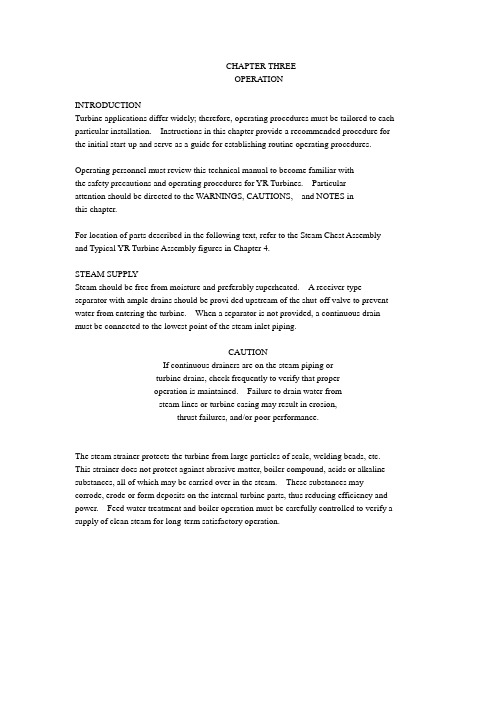
CHAPTER THREEOPERA TIONINTRODUCTIONTurbine applications differ widely; therefore, operating procedures must be tailored to each particular installation. Instructions in this chapter provide a recommended procedure for the initial start-up and serve as a guide for establishing routine operating procedures.Operating personnel must review this technical manual to become familiar withthe safety precautions and operating procedures for YR Turbines. Particularattention should be directed to the WARNINGS, CAUTIONS, and NOTES inthis chapter.For location of parts described in the following text, refer to the Steam Chest Assembly and Typical YR Turbine Assembly figures in Chapter 4.STEAM SUPPL YSteam should be free from moisture and preferably superheated. A receiver type separator with ample drains should be provi ded upstream of the shut-off valve to prevent water from entering the turbine. When a separator is not provided, a continuous drain must be connected to the lowest point of the steam inlet piping.CAUTIONIf continuous drainers are on the steam piping orturbine drains, check frequently to verify that properoperation is maintained. Failure to drain water fromsteam lines or turbine casing may result in erosion,thrust failures, and/or poor performance.The steam strainer protects the turbine from large particles of scale, welding beads, etc. This strainer does not protect against abrasive matter, boiler compound, acids or alkaline substances, all of which may be carried over in the steam. These substances may corrode, erode or form deposits on the internal turbine parts, thus reducing efficiency and power. Feed water treatment and boiler operation must be carefully controlled to verify a supply of clean steam for long-term satisfactory operation.Chapter 3OperationSAFETY PRECAUTIONS1. Do not operate the turbine if inspection shows that the rotor shaft journals and/or shaft packing case areas are corroded.2. Before starting, verify the rotor rotates freely by hand and that it is not rubbing any stationary parts.CAUTIONDo not rotate shaft until lubrication has been applied.Rotating the shaft without lubrication may result indamage to the rotor shaft and bearing liners .If rubbing or vibration occurs during operation,immediately shut down the turbine, investigate andcorrect the cause.3. Verify all piping (steam, water, air) and electrical connections are made before operating the turbine.4. Verify that all valves, controls, trip mechanisms and safety devices are in good operating condition.-WARNING-UNDER NO CIRCUMSTANCES SHOULD THE TRIPV ALVE BE BLOCKED OR HELD OPEN TO CAUSE THETRIP SYSTEM TO BECOME INOPERA TIVE.OVERRIDING THE TRIP SYSTEM AND ALLOWING THETURBINE TO EXCEED THE RATED (NAMEPLATE) TRIPSPEED MAY RESULT IN FATAL INJURY TOPERSONNEL AND EXTENSIVE TURBINE DAMAGE.IN THE EVENT THE TRIP SYSTEM MALFUNCTIONS:IMMEDIATEL Y SHUT THE TURBINE DOWN BYCLOSING THE INLET STEAM SHUT-OFF V ALVE.5. Before initial start-up, after major maintenance and after an extended shutdown, do not leave the turbine unattended at any time until proper operation with load has been Demonstrated.PREPARING THE TURBINE FOR INITIAL START-UPNOTEComplete installation work before attempting to operateturbine. (Refer to Chapter 2.)1. Disconnect the coupling between the turbine and driven machine. Turbines driving through reduction gears can remain coupled to the gear and operated together.2. Disconnect the steam inlet piping at the turbine and blow out the line with the supply steam to remove any foreign material from the pipe. Use targets for determination of cleanliness. (Refer to NEMA SM23 section 8.4 for additional details.)3. Verify the steam strainer is clean and properly installed in the steam chest inlet flange. Connect the pipe to the turbine as a permanent joint. Adjust piping hangersto eliminate any unacceptable strain on the turbine in cold and hot conditions. Piping strains must be calculated in agreement with current NEMA SM23 standards.4. If operating a condensing turbine, clean rust preventative compound from internal turbine surfaces.CAUTIONRust preventative compound will foul surfacecondenser tubes if not removed before operating theturbine.NOTEAs an alternative to manually cleaning the turbine internalsto remove rust preventative compound, the turbine may berun for several hours while exhausting to atmosphere.5. Remove bolting from the steam end bearing cap and the exhaust end bearing cap. Lift the caps approximately 1 inch (25 mm) and pry out the top bearing liners torelease the oil rings (if supplied). Remove the bearing caps and roll out the bottom bearing liners by lifting up on the rotor and rotating the bearing liners toward the positioning lugs. Clean and inspect the bearing liners. Keep the steam and exhaust end bearing liners separate.CAUTIONAttempting to remove the bearing caps without pryingout the top bearing liners can distort the oil rings.Distorted oil rings will not rotate and fail to provideadequate lubrication, resulting in bearing failures.NOTETurbines with Class 3 (or higher) rotors are pressurelubricated and may not have oil rings supplied. (Refer tothe Turbine Operating Data page located in the front of thismanual to determine the rotor class.)6. Clean the rotor shaft journals, locating bearing, and the bearing housings with clean,lint free rags. If turbine is equipped with Kingsbury type thrust bearings, removethrust bearings and clean; reassemble per Supplement 03-91, located in Chapter 8 Accessories.7. Lift the weight off the rotor and roll the bottom bearing liners into place. Make certainthe positioning lugs on the liners are correctly seated in the bearing housing locatinggrooves.CAUTIONVerify that the steam end and exhaust end bearingliners are not interchanged.8. Place the top bearing liners on the shaft journals. If the turbine is ring oiled, positionoil rings in the slots of the top liners. Flood the rotor locating bearing, shaft journals,and bearing liners with oil. (Refer to Chapter 5 for proper oil levels and lubrication requirements.)9. Replace the bearing caps. Verify that the positioning lugs on the top liners engagethe grooves in the bearing caps. Apply a very thin coat of sealant to the split line.Insert the dowel pins and tighten all bolts.10. If supplied, review the driven machine instruction manual for pre-start inspection procedures.11. Inspect the governor linkage. For specific details on preparing the governor for start-up, refer to Chapter 6, and the governor manuals located in Chapter 8 Accessories.12. Verify that all lube oil piping has been installed and the lubrication system has been flushed.CAUTIONIf the turbine is pressure lubricated, verify orifice plugsare installed at the bearing housings. If orifice plugsare not installed, oil leakage will occur.13. Verify free movement and clearances of the trip system. Manually activate theoverspeed trip pin to verify the ov erspeed trip system is functional.14. Fabricate a clamp or other blocking device to secure the coupling sleeve (if supplied) to the hub while operating the uncoupled turbine.NOTEUse a balanced adapter to secure balanced gear typecoupling hubs during uncoupled operation.15. Verify that the exhaust relief valve is installed correctly and operates at the correct pressure.-WARNING-THE TURBINE SHOULD NOT BE OPERATED UNLESSTHE A TMOSPHERIC RELIEF V ALVE OR OTHERPROTECTIVE DEVICE HAS BEEN INSTALLEDBETWEEN THE TURBINE EXHAUST CONNECTIONAND FIRST EXHAUST ISOLATION V ALVE (ORCONDENSER, IF THE TURBINE IS A CONDENSINGTURBINE).THE A TMOSPHERIC RELIEF V ALVE OR OTHERPROTECTIVE DEVICE MUST BE DESIGNED FOR FULLRELIEF OF THE MAXIMUM STEAM FLOW THROUGHTHE TURBINE WITHOUT EXCESSIVE EXHAUSTPRESSURE.FAILURE TO INSTALL THIS TYPE OF DEVICE MAYRESULT IN SEVERE EQUIPMENT DAMAGE AND/ORSEVERE INJURY OR DEATH TO PERSONNEL.16. Fill oil lubricators (if ring oiled) or oil reservoir (if pressure lubricated) with proper oil. (Refer to Chapter 5 for details.)17. Inspect and test all controls, alarms, trips and relief valves. Calibrate and install all instrumentation.18. Roll the shaft by hand through several revolutions, checking for possible binding or rubbing. Any sign of binding or rubbing should be thoroughly investigated before attempting to start the unit.19. If automatic controllers or regulators are supplied, do not enable during initial start-up; use only after the general operation of the equipment has been determinedsatisfactory.INITIAL START-UP1. Open drain valves to drain water from the steam inlet piping, turbine casing, steam chest, and the exhaust piping.2. V erify that the lube oil temperature is greater than 70°F (20°C).3. If turbine is ring oiled, check that oil lubricators are filled. If turbine is pressure lubricated, prime the oil pump(s) and verify that the oil reservoir is filled to the correct level. Start the auxiliary oil pump (if supplied) and circulate the lubricating oil. Check the oil piping for leaks and that oil is being delivered to the bearings.4. Adjust the governor speed setting to minimum speed. (Refer to “Governor Operation” in Chapter 6.)5. Completely open the overload hand valves (if supplied). For further details review the section on overload hand valves in this chapter.6. V erify that the trip valve is closed and open the turbine exhaust isolation valve.7. V erify proper oil pressure is present (pressure lubricated with auxiliary oil pump only).8. Latch the trip valve resetting lever.9. Commission the eductor/ejector (if supplied).NOTEWhen ejectors/eductors are used on packing case leakofflines, the customer can turn on at their discretion.However, care must be taken to prevent steam fromblowing out of packing cases along the turbine shaft, whichmay contaminate oil in bearing housings.10. Close the intermediate leakoff valve (BYRHH and optional on BYRH turbines) and maintain closed position until leakoff pressure builds to line pressure.11. For condensing turbines, close all drain valves and commission main condenser according to manufacturer’s instructions.12. Slowly open the main steam isolation valve until the turbine reaches approximately 500 rpm.CAUTIONSteam should not be admitted to the turbine casing bypartially opening the main steam isolation valve while the rotor is stationary. This condition will cause uneven heating of the turbine rotor and casing, which may result in a distorted casing, bowed rotor shaft or other related problems.13. For condensing turbines, adjust the sealing steam supply valve to permit a slight amount of steam to be discharged from the packing case leakoff drain lines. Apressure of 3 to 5 psig (0.20 to 0.35 bar) is usually sufficient sealing steam pressure. However, care must be taken to prevent steam from blowing out of the packing casesand along the turbine shaft.CAUTIONIf sealing steam is allowed to leak into the bearinghousings, the lubricating oil may becomecontaminated and form sludge and foam. To preventthis condition, adjust the sealing steam accordingly.14. Immediately verify operation of the trip valve by striking the trip lever. Close the main steam isolation valve as the turbine speed decreases.15. Latch the resetting lever and slowly open the main steam isolation valve to bring the turbine back to 500 rpm. If the turbine is ring oiled, remove the inspection plugs fromthe bearing caps and check to be sure the oil rings are rotating. Verify proper oilpressure is present (pressure lubricated only). Monitor the speed carefully during thelow speed operation.CAUTIONDo not leave the turbine unattended at any time duringthe initial start-up.16. Introduce cooling water to bearing housing cooling chambers or oil cooler (if supplied) to prevent overheating. (Refer to Chapter 5 [Table 5-3], for recommended bearing operating temperatures.)17. Listen for any unusual noises, rubbing, or other signs of distress in the turbine. Do not operate if any of these conditions are present. Monitor the turbine for signs of overheating and excessive vibration. (Refer to the Troubleshooting Guide in Chapter7 for possible causes and corrective actions for abnormal conditions which mightoccur.)18. When the turbine is thoroughly warmed up and low speed operation is determined tobe satisfactory, close the overload hand valves (if supplied).19. For non-condensing turbines, close all drain valves provided no signs of condensateare visible at all drain lines.20. Proceed with wearing in of the carbon rings (if supplied). (Refer to Turbine Operating Data Sheet located in the front of this manual, for steam seals supplied with this unit.)a. Gradually increase turbine speed to 1000 rpm and hold for 10-15 minutes.b. Reduce turbine speed to 500 rpm and hold for 5-10 minutes, allowing shaft tocool.c. Increase turbine speed by 1000 rpm and hold for 10-15 minutes.d. Reduce turbine speed by 500 rpm and hold for 5-10 minutes, allowing shaft tocool.e. Continue increasing turbine speed by 1000 rpm and decreasing by 500 rpm untilrated operating speed as shown on the turbine nameplate is achieved.NOTEThe stepped start up procedure (wearing in of the carbonrings) must be done for the first 2 or 3 turbine starts, orafter installation of new carbon rings. Failure to do so mayresult in improper wearing in of carbon rings and causeexcessive packing case steam leakage.21. After the turbine is operating, closely observe oil pressures and temperatures. For condensing turbines, adjust sealing steam to maintain 3 to 5 psig (0.20 to 0.35 bar).22. Verify the overspeed trip by temporarily overriding the governor to actuate the overspeed trip mechanism. (Refer to Control System, Chapter 6, for specific detailson overspeeding the turbine.)CAUTIONDo not operate the turbine more than 2% above therated trip speed listed on the turbine nameplate. If theoverspeed trip does not operate within 2% of thedesignated speed, shut the turbine down and makenecessary adjustments as described in Chapter 4,Overspeed Trip System.Three consecutive, non-trending trip speeds within the required range (refer toTurbine Data sheet located in the front of this manual) must be recorded to verify safe trip system operation. After a turbine trip and the speed decreases by 15-20% ofrated speed, the resetting lever may be relatched and the turbine brought back up in speed.-WARNING-DURING TESTING OF THE MECHANICAL OVERSPEEDTRIP, THE FOLLOWING GUIDELINES MUST BEADHERED TO:A. LIMIT PERSONNEL TO THE MINIMUM NUMBERREQUIRED TO CONDUCT THE OVERSPEEDTESTS.B. THE MAIN STEAM ISOLATION V ALVE TO THETURBINE MUST NOT BE FULL Y OPENED. ITSHOULD ONL Y BE OPENED AS FAR ASNECESSARY TO REACH THE TRIP SPEED.C. DURING THE TEST, TRAINED PERSONNEL MUSTOPERATE THE MAIN STEAM ISOLATION V ALVETO THE TURBINE.D. TWO SOURCES OF SPEED INDICATION AREPREFERRED. BOTH SHOULD BE OF KNOWNACCURACY AND CURRENT CALIBRATION.23. Continue operating the turbine for approximately one hour, while carefully monitoring bearing temperatures, turbine speed, vibrations levels, and listening for any unusual noises.24. Shut down the turbine upon satisfactory completion of the initial run. (Refer to “Turbine Shut Down” at the end of this chapter.)25. Couple the turbine to the driven equipment. If the turbine is used with a speed reduction gearbox or other special equipment, follow all instructions pertaining tothose particular items.ROUTINE START-UP1. V erify proper oil pressure is present (pressure lubricated only).2. Open drain valves to drain water from the steam inlet piping, turbine casing, steam chest, and the exhaust piping.3. V erify that the lube oil temperature is greater than 70°F (20°C).4. If turbine is ring oiled, check that oil lubricators are filled. If turbine is pressure lubricated, prime the oil pump(s) and verify that the oil reservoir is filled to the correctlevel. Start the auxiliary oil pump (if supplied) and circulate the lubricating oil.5. Completely open the overload hand valves (if supplied). For further details, review the section on overload hand valves in this chapter.6. V erify that the trip valve is closed and open the turbine exhaust isolation valve.7. Latch the trip valve resetting lever.8. V erify proper oil pressure is present (pressure lubricated with auxiliary oil pump only).9. Commission the eductor/ejector (if supplied).NOTEWhen ejectors/eductors are used on packing case leakofflines, the customer can turn on at their discretion.However, care must be taken to prevent steam fromblowing out of packing cases along the turbine shaft, whichmay contaminate oil in bearing housings.10. Close the intermediate leakoff valve (BYRHH and optional on BYRH turbines) and maintain closed position until leakoff pressure builds to line pressure.11. For condensing turbines, close all drain valves and commission main condenser according to manufacturer’s instructions.12. Slowly open the main steam isolation va lve until the turbine reaches approximately 500 rpm.CAUTIONSteam should not be admitted to the turbine casing bypartially opening the main steam isolation valve whilethe rotor is stationary. This condition will causeuneven heating of the turbine rotor and casing whichmay result in a distorted casing, bowed rotor shaft orother related problems.13. For condensing turbines, adjust the sealing steam supply valve to permit a slight amount of steam to be discharged from the packing case leak off drain lines. A pressure of 3 to 5 psig (0.20 to 0.35 bar) is usually sufficient sealing steam pressure. However, care must be taken to prevent steam from blowing out of the packing casesand along the turbine shaft.CAUTIONIf sealing steam is allowed to leak into the bearinghousings, the lubricating oil may becomecontaminated and form sludge and foam. To preventthis condition, adjust the sealing steam accordingly.14. Immediately verify operation of the trip valve by striking the trip lever. Close the main steam isolation valve as the turbine speed decreases.15. Latch the resetting lever and slowly open the main steam isolation valve to bring the turbine back to 500 rpm. If the turbine is ring oiled, remove the inspection plugs fromthe bearing caps and check that the oil rings are rotating. If the turbine is pressure lubricated, verify proper oil pressure is present.16. Introduce cooling water to bearing housing cooling chambers or oil cooler (if supplied) to prevent overheating. (Refer to Chapter 5 [Table 5-3] for recommended bearing operating temperatures.)17. Listen for any unusual noises, rubbing, or other signs of distress in the turbine. Do not operate if any of these conditions are present. Monitor the turbine for signs of overheating and excessive vibration. (Refer to the Troubleshooting Guide in Chapter7 for possible causes and corrective actions for abnormal conditions which might occur.)18. For non-condensing turbines, close all drain valves, provided no signs of condensate are visible at all drain lines.19. Adjust governor to attain desired speed as load is applied to the turbine. (Refer to “Control System”, Chapter 6). Close ov erload hand valves as required by turbine operation. (Refer to the “Unit Outline” in Chapter 10, Technical Drawings, foroverload hand valve settings.)20. After the turbine is operating, closely observe oil pressures and temperatures. For condensing turbines, adjust sealing steam to maintain 3 to 5 psig (0.20 to 0.35 bar).OVERLOAD HAND V ALVES (Optional)Overload hand valves are used sometimes to control the steam flow through an extra bank of nozzles. These valves can serve three functions:a. When closed, the valves will provide more efficient turbine operation at reduced load with normal steam conditions by reducing the nozzle area and also reducing thesteam flow.b. In some applications, overload hand valves are used to develop the required powerby opening the valves when steam conditions are less than normal (such asencountered during boiler start-up).c. Sometimes overload hand valves are used to develop increased power for meeting overload requirements with normal steam conditions.(Refer to the “Turbine Outline” in Chapter 10, Technical Drawings, for overload hand valve positioning versus turbine power, speed and operating steam conditions.) For the bestefficiency and speed control, open only the overload hand valves required for the actual steam conditions present and power required.TABLE 3-1OVERLOAD HAND V ALVESTurbine Frame Size Number of TurnsAYR 7BYR, BYRIH 9CYR, CYRH 12DYR, DYRH, DYRM, DYRN 12DYR, DYRH, DYRM, DYRNwith 8" inlet14BYRH, BYRHH 12NOTEOverload hand valve must be positioned either completelyopen or completely closed. Turning the stemcounterclockwise approximately 1½ turns will open thepilot valve. (Refer to Table 3-1 for the correct number ofturns required to completely open the main valve disk.)Open all overload hand valves during start-ups to verifyeven heating of casing and prevention of valves binding inthe casing. The overload hand valves can be completelyclosed if not needed when governor control is reached.CAUTIONOperation of the overload hand valve, in anythingother than completely open or completely closedposition, can cause valve failure and possible internaldamage to the turbine.For further information on Auto-Overload hand valves (if supplied), refer to Supplement 02-86-R1, in Chapter 8.TURBINE SHUTDOWNCAUTIONBefore shutting down turbine, verify that the governorsystem and trip system are in proper working order. Ifthe operational integrity is uncertain, shut off the mainsteam isolation valve to stop the turbine.1. Reduce the turbine speed to a minimum.2. Shut down the turbine by striking the top of the trip lever by hand.3. Observe the action of the trip valve and linkage.4. Close the main steam isolation valve.NOTEIsolation valves, located in the turbine inlet steam piping,must be closed after the trip valve has closed. Do not usethe trip valve as a long-term shut-off valve.5. If non-condensing turbine, close the exhaust valve and open turbine casing drains.6. If condensing turbine, shut down the condensing equipment, open the turbine casing drains and close the sealing steam shut-off valve.CAUTIONDo not apply sealing steam to the packing cases whilethe turbine rotor is idle. This condition will causeuneven heating of the turbine rotor and casing whichmay result in a distorted casing, bowed rotor shaft orother related problems.7. Allow the rotor to come to a complete stop and cool down for approximately 2 hours before turning off the cooling water or stopping auxiliary oil pump, if supplied.8. If the turbine is to be taken out of service for an extended period, follow the storage instructions in Chapter 1.OPERATION OF EMERGENCY AND STANDBY TURBINESEmergency and standby turbines do not require a warm-up period before applying the load and may be rapidly placed into service. However, it is important that turbines used for emergency and standby services have drain li nes open and isolating valves closed whenthe turbine is idle. Turbines not used for extended periods should be inspected and operated occasionally to verify good working condition.Where impractical to operate the turbine, the rotor should be turned over by hand to introduce oil to the journal bearings (oil ring lubricated turbines). If an auxiliary oil pump is furnished (pressure lubricated turbines), oil can be supplied to the bearings by operatingthe pump. To prevent corrosion, introduce dry, heated air into the casing during shutdown periods.CAUTIONSteam should not be admitted to the turbine casing bypartially opening the main steam isolation valve whilethe rotor is stationary. This condition will causeuneven heating of the turbine rotor and casing, andmay result in a distorted casing, bowed rotor shaft orother related problems.。
丙烯压缩机油路系统共36页

谢谢你的阅读
❖ 知识就是财富 ❖ 丰富你的人生
71、既然我已经踏上这条道路,那么,任何东西都不应妨碍我沿着这条路走下去。——康德 72、家庭成为快乐的种子在外也不致成为障碍物但在旅行之际却是夜间的伴侣。——西塞罗 73、坚持意志伟大的事业需要始终不渝的精神。——伏尔泰 74、路漫相称。——韩非
丙烯压缩机油路系统
21、没有人陪你走一辈子,所以你要 适应孤 独,没 有人会 帮你一 辈子, 所以你 要奋斗 一生。 22、当眼泪流尽的时候,留下的应该 是坚强 。 23、要改变命运,首先改变自己。
24、勇气很有理由被当作人类德性之 首,因 为这种 德性保 证了所 有其余 的德性 。--温 斯顿. 丘吉尔 。 25、梯子的梯阶从来不是用来搁脚的 ,它只 是让人 们的脚 放上一 段时间 ,以便 让别一 只脚能 够再往 上登。
丙烷压缩机培训课件
丙烷压缩机培训课件丙烷压缩机培训课件丙烷压缩机是一种常见的工业设备,广泛应用于石油化工、制冷空调、能源等领域。
为了提高员工对丙烷压缩机的理解和操作技能,培训课件是一种常见的培训方式。
本文将从丙烷压缩机的工作原理、安全操作、维护保养等方面进行论述,以帮助读者全面了解丙烷压缩机。
一、丙烷压缩机的工作原理丙烷压缩机是一种能够将气体压缩成高压气体的设备。
它通过机械运动将气体吸入压缩腔,然后利用活塞或叶片等压缩元件将气体压缩,最终将高压气体排出。
这个过程中,丙烷压缩机需要消耗能量,通常通过电机提供动力。
二、丙烷压缩机的安全操作1. 熟悉设备:在操作丙烷压缩机之前,必须熟悉设备的结构和工作原理,了解各个部件的功能和作用。
只有对设备有足够的了解,才能够进行安全操作。
2. 防护措施:在操作丙烷压缩机时,必须佩戴个人防护装备,如安全帽、护目镜、防护手套等。
这些防护措施可以有效地保护操作人员的安全。
3. 操作规程:在操作丙烷压缩机之前,必须仔细阅读操作手册,并按照规程进行操作。
任何违反规程的行为都可能导致事故的发生。
三、丙烷压缩机的维护保养1. 定期检查:丙烷压缩机需要定期进行检查,以确保其正常运行。
检查的内容包括设备的各个部件是否完好,是否有漏气现象等。
2. 清洁保养:丙烷压缩机需要定期清洁,以防止灰尘和杂物堆积,影响设备的正常运行。
清洁时要注意使用合适的清洁剂,并遵循清洁的步骤和方法。
3. 润滑维护:丙烷压缩机的各个部件需要进行润滑维护,以减少摩擦和磨损。
在进行润滑维护时,要使用合适的润滑油,并按照规定的周期进行润滑。
四、丙烷压缩机的故障排除1. 常见故障:丙烷压缩机常见的故障包括漏气、压力不稳定、噪音过大等。
当发生故障时,应及时进行排除,以保证设备的正常运行。
2. 故障排查:在排除故障时,首先要确定故障的原因,然后采取相应的措施进行修复。
在排查故障时,要注意安全,并遵循相应的操作规程。
五、结语通过本文的介绍,相信读者已经对丙烷压缩机有了更深入的了解。
丙烯压缩机油路系统
过高时,它可以自动关小调节汽门使汽轮机 转速下降;
3、速关装置
3.1 速关装置油路走向 高压油从“P”进入基本模块,在基本模块壳体内分为五路:
• 第一路经手动停机阀(2274)和电磁阀(2225)进入停 机卸荷阀 (2030),克服弹簧力使阀处于关闭状态。正常 运行时,通向停机卸荷阀的速关油不泄油。速关油是由冗 余模块内部管路引入的。
油温:40±5℃ 润滑油压:0.25~0.35MPa 调速油压: 0.85MPa 油过滤器压差:<0.15MPa 主油泵出口压力:1.1MPa 油箱液位:液位计60% 回油温度:<85℃ 氮气压力为:200mmH2O,氮气流量:10Nm3/h。
二、调速系统
• 1.汽轮机调速系统的任务 • 1.1.1使汽轮机组输出的功率与负荷保持平
• 速关阀在线试验阀 (1845)
• 供速关阀活塞做活动 性试验
3.3.2 冗余模块
组成
功能
• (2226)电磁阀
• 电动紧急停机
• (2040)停机卸荷阀 • 快速卸掉速关油压
3.3.3 启动模块
组成
功能
• (1839)启动阀 • (1830)关闭阀 • (1742)电液转换器 • (5600)单向阻尼阀
讲述ቤተ መጻሕፍቲ ባይዱ容
一、润滑油系统: 1、润滑油的作用 2、油路的介绍 3、油系统主要设备介绍 4、高位油槽与蓄压器 5、润滑油系统控制指标
二、调速器系统
1、调速器的任务 2、调速系统的油路介绍 3、速关装置 4、紧急停车的原理 5、建立启动油、速关油、开
启速关阀
6、速关阀在线试验 7、错油门与油动机 8、电液转换器原理 9、盘车系统
压缩机基本知识资料PPT课件

◆ 故障现象: A、绝缘耐压不良
B、接线柱击穿
◆ 解析现象: A、接线柱玻璃体融化 B、接线柱冲出
◆ 产生机理:
空调系统残留有氧化皮随冷媒冲注进入压缩机,冷媒的张力使氧化、
皮浮于压缩机最上部,粘附在接线柱内面玻璃体,缩短了接线柱与
外壳的爬电距离(3mm以下),通电时 “闪烙”烧损产生的高温
融化
玻璃体,接线柱在机内压力作用下冲出。
产生电解还原作用,造成泵体部品镀铜,同时使冷冻机油劣化,压缩机冷却
不足产生高温。同时水分使部品生锈;冷冻机油劣化后润滑不良造成运转部
品磨损大。
◆ 解析图例:
第35页/共37页
第 35 页
非压缩机制造不良:空调系统冷媒泄漏
振
动使异物划破相邻铜线的绝缘漆造成导通后短路烧损。
B、空调系统中的异物掉在线圈表面,运转时线圈铜线间
的
振异动物使掉异入物烧损划点破相邻铜线的绝缘漆造成导通后短路烧
损。
◆ 解析图例:
马达铜线
第28页/共37页
第 28 页
压缩机制造不良:线圈线伤
◆ 故障现象: A、绝缘不良
B、不能起动
C、电流大
◆ 解析现象: A、线圈局部烧损,绝缘物融化 B、线圈外观无异常
压缩机系列标志(P、K等)
制冷剂种类标志: 例:2—R22 4—R407C 5—
R410A
第9 页
压缩机的生产日期命名方式
生产日期(例):
07 05 10 W 17
时刻 松下·万宝的标记 日期
月度 年度 表示此台压缩机的生产时间为:07年5月10日17时生产的。
第10页/共37页
第 10 页
第二部分
造成定子线圈绝缘物全部融化或线圈单相(全相)烧损。
压缩机学习幻灯片

供应商评估和选择方法
供应商资质
评估供应商的营业执照、 税务登记证等资质是否齐 全。
服务能力
考察供应商的售前、售中、 售后服务能力,包括技术 支持、培训等。
产品质量
了解供应商的产品质量水 平,包括合格率、退货率 等指标。
价格水平
对供应商的价格进行合理 比较,选择性价比较高的 产品。
合同签订注意事项
故障诊断与排除技巧
压力异常
温度过高
检查进气阀、排气阀及密封件是否损坏,及 时更换或修复。
检查冷却系统是否畅通,清洗冷却器;检查 润滑油油位、油质,及时更换或补充润滑油。
异常响声
漏气故障
检查各部件紧固情况,发现松动及时紧固; 检查轴承、齿轮等部件磨损情况,及时更换 或修复。
检查管道、法兰、阀门等连接处是否漏气, 及时紧固或更换密封件。
体的压缩
控制气体的吸入和排出, 保证压缩过程的顺利进
行
将电机的旋转运动转化 为活塞的往复运动
结构形式对比分析
活塞式压缩机
结构简单,易于维护,但转速较 低,效率相对不高
螺杆式压缩机
结构紧凑,转速高,效率高,但维 护成本相对较高
离心式压缩机
结构复杂,转速极高,效率也很高, 但制造成本和维护成本都很高
性能参数与选型依据
日常维护与保养方法
清洁工作
定期清理压缩机内外部灰尘、油污等杂物, 保持设备清洁。
冷却系统维护
定期检查冷却水水质、水位及冷却效果,清 洗冷却器水垢,保证冷却系统畅通。
润滑保养
定期检查润滑油油位、油质,及时更换或补 充润滑油,保证各部件润滑良好。
安全附件检查
定期检查安全阀、压力表等安全附件的灵敏 度和准确性,确保设备安全运行。
丙烯制冷压缩机组密封油系统漏油的原因及解决措施
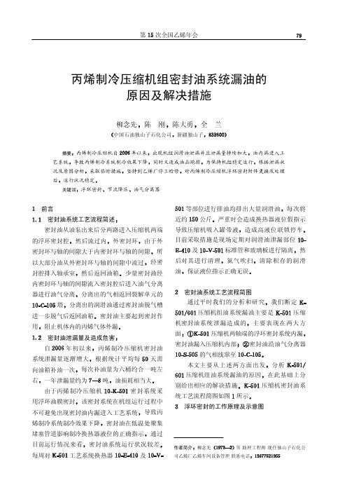
作者简介柳念先男助理工程师现任独山子石化公司乙烯厂乙烯车间设备管理联系电话丙烯制冷压缩机组密封油系统漏油的原因及解决措施陈刚陈大勇全兰摘要丙烯制冷压缩机自年以来出现机组润滑油泄漏并且泄漏量持续加大油内漏进入工艺系统同时又造成油品跑损为保持机组稳定运行根据泄漏状坚持到乙烯厂停工检修对丙烯制冷压缩机浮环密封附件更换及处理后关键词油气分离器前言密封油从油泵出来后分两路进入压缩机两端然后流过内由于外所经密封腔排入轴承室少量密封油经内密封环与轴的间隙流入密封腔后进入油气分离器进行油气分离分离出的气相返回裂解单元的分离出的润滑油通过密封油脱气槽密封油主要起到密封作自丙烯制冷压缩机密封油根据统计平均每天需向油箱补油一次每次补油量为六桶约合一吨左一年泄漏量约为由于丙烯制冷压缩机密封系统采用浮环油膜密封该密封系统在机组运行过程中导致丙烯制冷系统制冷效果下降密封油在低温处聚集通过每周对工艺系统换热器及每次将近约严重时会造成换热器液位假指示目前采取措施是现场定期对润滑油泄漏部位及然氮气吹扫清除积存的润滑油密封油系统工艺流程简图通过平时我们的分析和研究我们断定压缩机组油系统漏油主要是压缩主要表现在两大方面的气相线窜至分析压缩机组油系统漏油的原因在此基础上分压缩机密封油系统工艺流程简图如图浮环密封的工作原理及示意图图密封油系统工艺流程简图浮环密封是一种轴向和径向密封组合的混合密封浮环密封主要是由高压环环低压环环防转弹簧以及辅助密封等部高压环的作用是利用高压密封油在浮环与轴间形成的油膜产阻止所密封的气体通过浮环与轴套间的间隙沿轴向外漏但会有少量密封油从此间隙中向密封气体侧泄漏因高压环两侧压差较小低压环的作用是利用高压密封油在浮环与轴间形成的油膜产生节流降压阻止密封油流向低压侧使密因低压环两侧压差较大为防止泄油量过大视情况低压环防转销的作用是只允许浮环随轴浮动防止浮环随辅助密封的作用是与壳体的静端面轴向紧密贴和防止气体沿径向浮环与轴轴之间充满了密封由于浮环与轴之间存在偏心当轴转动时在偏心圆柱间隙内将形成的油膜产生流体动压力浮环密封主要是油膜起作用浮环密封浮环密封系统内漏的原因分析浮环密封中外环只起保压作用浮环密封系统无论外环还是内环它们的漏油量的计算公式均如下式中影响浮环漏油量的因素有密封环与轴之间的密封间隙正比于以当密封间隙每增大而密封油漏油量却要增加提高密封效果看浮环间隙应尽量减小但间隙太小又会导致浮环工作条件的恶化乃至浮环抱轴故障的发生浮环间隙过大浮环间隙一般在下列范围选取内浮环半径间隙外浮环半径间隙中年我们所测得的浮环内环间隙在大检浮环间隙不是导致浮环密封系统中内浮环两侧压差正比于即压差越漏油量是相对偏心度密封油漏油量正比于则漏油量越大则漏说明浮环和轴之间没有磨损所以偏心度不应该发密封油泄漏量与密封油粘度成反比而流体的粘度又是随其温度的升所以则油的粘密封油的温度越低节流长度密封油泄漏量与密封浮环即节流长度越长漏油量越小节流长度越短在浮环密封系俘环的轴向尺寸不会发生变化除上述外还有以下一些原因可能引起浮环密封内漏量增大内环中作为辅助密封的用于径向密封的由于零配件损坏或存在杂质或机组检修时装配质量问题浮环间隙不能造成密封油回油不或者气气压差不稳或者气气压差信号变送器灵敏度出现问题汽轮机转速波动也会影响浮环密封油膜的形成造成密封失综上所述结合我装置具体情况我们分析泄漏原因主要有以下两方面压缩机密封系统采用浮环油膜密封从年月检修到现在已经机组密封系统浮环油膜密封组件磨损严重密封油漏进工艺系统密封油脱气系统油气分离器的工作状况较差从而密封油随气相线窜到系统外加大了密封油的损失密封油系统泄漏的解决措施在年我们有针对性的采取了一些措施首先对密封油系统进行了检修此外环解体检查发现基密封油系统油气分离器气由以前的更改为目前的油气分离器解体检查发现于是对气相线及回油线进行了其次在工况允许的情况下控制密封油高位槽的液位尽量降低油气压差油气压差由检修前的降到目前的同时对气提同时确保密封油应干净无水分及机械杂质参考气之间的关系密切注意各参数的变化通过以大检修前我们每周至少要对工艺系统段间罐和换热器至少排油一次而大检修后我们至今没有排过油可以说压缩机两轴端的浮检修后密封油泄漏量丙烯制冷压缩机于检修后月运行至目前密封油系统工作正常润滑油泄漏量月日机组运行到油箱液位略有下降根据油箱液位刻度进行估算泄漏量约为计公照此泄漏量计算每年润滑油损失约为比检修前减少泄漏近小结及建议由于压缩机密封系统采用浮环该密封系统在机组运行过程中不可避目前其他厂家大多采用较先进的干气密封系统建议我们在可行的条件下进行更换油气分离效果不好参考文献任晓善等化工机械维修手册化学工业出版社钱锡俊等编泵和压缩机石油大学出版社。
压缩机油路
油动机是调节汽阀的执行机构,它将由放大器或电液转换器输入的二次油信号转换为有足够作功能力的行程输出以操纵调节阀,控制汽轮机进汽。
油动机是断流双作用往复式油动机,以汽轮机油为工作介质,动力油用~0.8Mpa 的压力油。
油动机结构如图1 所示。
1.拉杆2.调节螺栓3.反馈板4.活塞杆5.油缸(缸盖)6.活塞7.连接体8.错油门(错油门壳体)9.反馈杠杆10.调节螺钉11.调节螺母12.弯角杠杆13.杆端关节轴承图1 油动机油动机主要由油缸、错油门、连接体和反馈机构组成。
错油门(8)通过连接体(7)与油缸(5)连接在一起,错油门与油缸之间的油路由连接体沟通,油路接口处装有O 形密封圈。
连接体有铸造和锻件加工两种,图示为铸件形式。
油缸由底座、筒体、缸盖、活塞、活塞杆等构成。
筒体与底座、缸盖之间装有O 形密封圈,它们由4 只长螺栓组装在一起。
活塞配有填充聚四氟乙烯的专用活塞环。
活塞动作时在接近上死点处有~10mm 的阻尼区,用以减小活塞的惯性力和载荷力并降低其动作速度。
缸盖上装有活塞杆密封组件,顶部配装活塞杆导轨及弯角杠杆支座。
油缸靠底座下部双耳环与托架上的关节轴承、销轴连接并支撑在托架上。
在油缸活塞杆(4)上端有拉杆(1)和杆端关节关节轴承(13),通过(13)使油缸与调节汽阀杠杆相连。
错油门结构如图2 所示。
套筒(25、26、27)装在错油门壳体(8)中,其中上套筒(25)及下套筒(27)与壳体用骑缝螺钉固定,中间套筒(26)在装配时配作锥销与壳体定位固定。
14.错油门弹簧15.推力球轴承16.转动盘17.滑阀体18.泄油孔19.调节阀20.放油孔21.调节阀22.喷油进油孔23.测速套筒24.喷油孔25.上套筒26.中间套筒27.下套筒C 二次油P 动力油T 回油图2 错油门套筒与壳体中的腔室构成5 档功用不同的油路,对照图1 可看出,中间是动力油进油,相邻两个分别与油缸活塞上、下腔相通,靠外端的两个是油动机回油。
丙烯压缩机 PPT课件

压缩机防喘振控制
• 喘振,也称之为飞动,是使透平压缩机性能反常的一种不
稳定的运行状态。透平压缩机发生喘振时,将出现整个压 缩机管网系统的气流周期性振荡现象。不但会使压缩机的 性能显著恶化,气体参数:压力、流量产生大幅度的脉动, 而且会发生一种“呼哧,呼哧”的噪音,并大大地加剧整 个机组的振动。喘振会使压缩机的转子和定子的元件经受 交变的动应力;级间压力失调引起强烈的振动,使密封和 轴承损坏;甚至发生转子与定子元件相碰、压送的气体外 泄、引起爆炸等恶性事故。
• 生产操作时的控制 • 1 丙烯闪蒸槽、丙烯分离器液位的控制
• 丙烯闪蒸槽、丙烯分离器均有液位调节,调节液
位时,液位不能调得过高,以防有液滴进入丙烯 压缩机,打坏叶轮,损坏压缩机,同时也不能过 低,以避免一、二段进气产生大的波动,造成压 缩机喘振。
• 丙烯闪蒸槽液位正常控制在450 mm,低限报警
6 工艺流程概述 丙烯流程:
开车时,液体丙烯从槽车导入丙烯贮槽(V2401), 然后依次导入丙烯闪蒸槽(V2402)、丙烯分离器 (V2403),最后通过液体丙烯管线去低温甲醇洗工 序。
• 装置正常生产时,从低温甲醇洗工序来的-40℃气体丙
烯,压力约0.02MPa, 进入丙烯分离器(V2403),气体 中的液滴分离出来后以42050 Nm3/h进入丙烯压缩机 (C2401)低压缸(一段)进口。
丙烯冷冻
一、工序的任务及意义
• 冷冻工序作为净化系统的辅助系统之一,由
净化岗位统一管理。 本工序使用汽轮机驱动离心式压缩机,丙烯
为介质,通过压缩、用水冷凝、节流降压蒸发, 达到制冷效果,提供冷量给低温甲醇洗系统中的 各深冷器补偿系统冷量损失。
《压缩机控制系统》PPT课件

• 平衡输出压力信号后的液压PA对磁力FHyd反向作用。
• 由于两股力相等,控制活塞就定位于“液压中心”,而且输出压力与给 定信号一致。在“液压中心”位置上,控制活塞在固定范围P→PA和 PA→T内做小幅的振动,以保持磁力FMag形成的输出压力PA。
• 当给定信号增大时,磁力FMag随之增大,控制活塞的位置发生改变, 从而使输出压力PA与输入压力Pin连通,并阻塞PA的回油线T1。
h
39
压缩机控制系统
控制系统维护
5. 卡件报警(FAULT/LOAD)
6.
只要ACTIVE灯亮,通常不会影
响卡件的正常工作。 可以拔出卡件再
重新插入, 如果有备用卡件,在生产
期间,可以先插入备卡。
h
40
压缩机控制系统
控制系统维护
6. 慎重拔出工作卡件
7.
生产期间,任何时候不能拔出
正在激活使用中的卡件。不要在任何整
• ·移除弹性挡圈。 • ·对照输出压力慢慢顺时针旋转手动操作旋钮。 • 操作提示:顺时针方向旋转增大输出压力。
h
27
压缩机控制系统
电液转换器 给定信号操作
打开电源,输出压力就可以由电位器×0 和×1设定的信号范围0/4…20mA进行调节。
h
28
压缩机控制系统
电液转换器
• 故障:压力波动
• 原因:1.液压部分含有气泡。
断压力源并消除泄漏。
h
26
压缩机控制系统
电液转换器
手动旋钮操作 • 可以断电操作手动控制旋钮。 • 在操作手动驱动旋钮时,由于输出信号压力的增加,
可能发生电液转换器输出控制的压力组件不受控制 的滑动。
• 手动操作只有在手动操作旋钮的弹性挡圈移除时才 可进行。
