车载GPS说明书
车载GPS导航仪使用说明书
车载GPS导航仪使用说明书尊敬的用户,欢迎您购买并使用我们的车载GPS导航仪。
本使用说明书将为您提供详细的操作指南,以帮助您正确使用导航仪并获得最佳的导航体验。
一、产品概述车载GPS导航仪是一种基于全球定位系统(GPS)技术的导航设备。
它结合了卫星定位、地图数据库和导航软件,能够为您提供准确的车辆位置信息、路线规划以及导航指引等功能。
我们的产品具有以下特点:1.高精度定位:通过接收卫星信号,导航仪能够实时准确地定位您的车辆,提供精准的导航服务。
2.多功能导航:除了常规的驾车导航功能外,导航仪还提供步行、骑行等多种导航模式,并支持POI(兴趣点)搜索、线路规划等功能。
3.智能语音提示:导航仪内置语音合成技术,能够实时播报导航指引,让您无需分心看屏幕,更加安全便捷地进行导航。
二、使用方法1.前期准备在第一次使用前,请确保您已经将导航仪的电源充满,并正确插入车载支架。
您还需要安装地图数据,可通过我们提供的软件或者在线下载的方式进行。
2.开机与关机长按开关键一秒钟,导航仪即可开机启动。
在正常使用过程中,您可以通过点击界面上的关机按钮进行关闭。
3.地图操作使用触摸屏幕或者外部键盘进行地图操作。
您可以通过手势缩放、平移等方式调整地图显示区域。
另外,点击地图上的兴趣点或者目的地图标,即可进行相关操作,如导航规划、查看详细信息等。
4.导航设置导航仪提供了丰富的导航设置选项,您可以根据个人需求进行调整。
例如,您可以选择偏好路线、避开拥堵、设置声音提示等。
5.语音指引导航仪通过内置扬声器进行语音指引。
在导航过程中,您会听到详细的导航提示,包括转向指示、距离提示等。
您还可以根据需要调整音量大小或者关闭语音指引。
6.兴趣点搜索导航仪允许您搜索周边的兴趣点,如餐馆、加油站、酒店等。
您可以直接在搜索框中输入关键词,系统会为您提供相关的搜索结果,并进行导航到达。
三、常见问题与解答1.为什么导航仪无法定位?请确保导航仪在开放的区域使用,避免遮挡。
车载GPS定位器TK116说明书
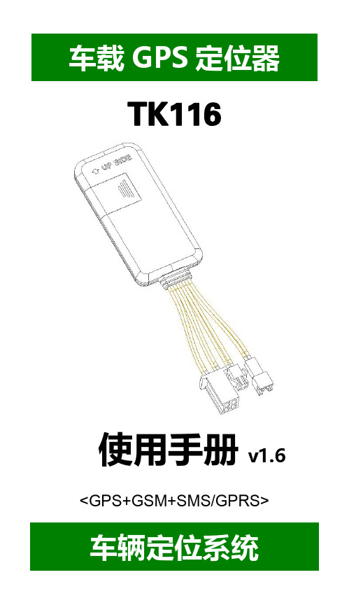
----TK116使用手册v1.6<GPS+GSM+SMS/GPRS>-车辆定位系统--目录一、产品功能、规格 (5)1.1产品功能 (5)1.2产品规格 (6)二、产品结构、配件 (7)2.1产品结构 (7)2.2产品配件 (8)三、安装SIM卡 (9)3.1安装前的准备 (9)3.2SIM卡的安装 (9)3.3取出SIM卡 (10)四、终端安装 (11)4.1安装设备到车辆 (11)4.2终端如何接线 (12)4.3继电器接线 (16)4.4安装麦克风 (16)4.5安装SOS求救按钮 (17)五、开启/关闭终端 (17)5.1开机 (17)5.2状态指示灯 (17)5.3关机 (18)六、查询、监听、切断/恢复油路..186.1短信查询 (18)6.2终端服务平台查询 (18)6.3终端监听 (19)6.4切断/恢复油路 (19)七、终端配置 (20)八、终端报警 (20)8.1振动报警 (20)8.2碰撞/跌落报警 (20)8.3速度报警 (20)8.4位移报警 (20)8.5电子围栏报警 (21)8.6剪线报警 (21)8.7低电报警 (21)8.8SOS报警 (21)九、故障排除 (22)9.1无法连接服务平台 (22)9.2后台显示离线状态 (22)9.3长时间不定位 (23)9.4定位漂移严重 (23)9.5指令接收异常 (23)十、保修细则 (24)10.1特别声明 (24)10.2保修期 (24)10.3售后服务 (24)Warranty Card/保修卡 (25)感谢您选用购买本机器,请您在使用之前认真阅读本说明书,以便得到正确的安装方法及操作指南,以下描述中终端等同于本机器。
产品外观及配色如有改动,请以实物为准,恕不另行通知。
TK116车用定位跟踪产品借助GPS卫星定位系统、GPRS通信和互联网,通过强大的服务平台可以实现对车辆进行实时远程监测和控制作用。
帮助客户实现透明管理、降低成本、保障安全、提高效率的目标。
汽车gps定位使用说明书20
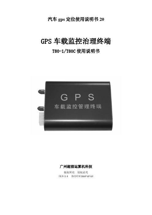
汽车gps定位使用说明书20GPS车载监控治理终端T80-1/T80C使用说明书广州超前运算机科技版权所有侵权必究〔版本2.0 修改时刻2010-10-13〕请先阅读本节◎感谢您购买本公司的产品,在使用产品之前,请认真阅读本说明书,并请遵守本书每一章节的操作和本卷须知。
当您开始使用产品时,本公司认为您差不多认真地阅读了本说明书。
◎本说明书提供的信息,经认真核对,务求精准。
如有任何印刷或翻译错误,本公司不承担因此产生的后果。
◎本设备属于高技术产品,本公司在硬件的制造过程和软件的开发以及运用过程中差不多尽到了充分的注意义务,以确保产品能够正常工作。
假如产品发生故障,本公司除了依照品质保证规定承担修理责任之处,关于用户因使用本产品而导致的财产损害和经济缺失不承担任何赔偿责任。
◎此说明书的所有著作权都归本公司所有,不得随意复制或翻译此说明书的全部或部分进行商业活动,本公司保留对此说明书内容的最终说明权。
◎本设备产品相关参数如有变更,恕不另行通知。
目录一.概述 (1)二.产品要紧功能 (1)三.要紧功能介绍 (2)3.1重点举荐功能 (2)3.2定位监控功能 (2)3.3报警装置功能 (2)3.4综合治理功能 (2)3.5地图功能 (3)四.GPS定位原理图 (3)五.产品安装与接线 (3)5.1手机卡安装 (3)5.2报警开关安装 (3)5.3现场调试检测 (3)5.4主机接线图 (4)六.包装清单 (4)七.安装本卷须知及爱护常识 (5)7.1安装本卷须知 (5)7.2爱护常识 (5)八.要紧技术参数 (5)九.故障排除 (5)十.售后服务 (6)一.概述T80系列产品〔T80-1/T80C〕是由广州超前运算机科技研发,具有卫星定位、手机查车功能、车辆实时报警、历史行驶轨迹回放及报表分析等功能,可对行驶车辆进行远程监控的车载监控治理终端。
T80系列车载监控治理终端,通过GPS系统提高了对车辆的有效治理,把握车辆实时位置、行驶速度、里程信息,可对车辆状况进行操纵,获得车辆安全信息等,对道路安全运输,预防道路交通事故发生,提高安全治理水平,落实科技兴安战略起到了决定性的作用。
汽车跟踪定位仪使用说明书[1]
![汽车跟踪定位仪使用说明书[1]](https://img.taocdn.com/s3/m/3f1db024ccbff121dd3683be.png)
GPS &GSM/GPRS 汽车跟踪定位仪使用说明书121. 安装操作说明1.1接口说明1: 扩展接口42: 扩展接口53: 断电路/油路4: ACC(12V)点火线5: DC(12V)6: 扩展接口37: SOS 紧急呼叫8: 扩展接口19: 扩展接口210: 电源地SIM 卡接口MIC/PHONE:耳机与话筒组合LED:状态指示灯LED状态指示LED灯全灭表示未工作,亮1秒灭1秒表示GSM注册成功亮0.1秒灭2.9秒表示GPS定位常亮表示GSM注册成功并且GPS定位1.2安装检查第一步:检查配件的完整性:主机盒、10Pin连接线、油路控制器、GSM天线、GPS天线、紧急报警报钮、说明书。
第二步: SIM准备购买SIM手机卡(只支持GSM网络,不支持CDMA和小灵通卡),记录好SIM卡对应的号码(即手机号码),SIM卡必须开通来电显示功能,否则无法进行电话监听。
第三步:安装注意电源DC(12V)、电源地与汽车电瓶的正负极、ACC(车钥匙打火)和GSM天线、GPS天线即可。
油路控制接法参照图纸,注意要请专业人员安装第四:GPS天线安装时必须正面朝上,平放对准天空第五:油路控制接线方法注意:油路控制器分12V和24V两种规格,所以在安装时一定要看清油路控制器上的标识规格。
3继电器SOS紧急呼叫42.使用说明3.1位置请求短信功能发送短信:A+密码+,+000(初始密码:000000)例如:A000000,000设备收到短信后,回复位置信息,格式如下:Longitude E114.04577 Latitude N22.32405 08-10-2017:38:30注:如果没有定位,则经纬度时间都是0,为无效值,时间为格林威治时间,具体时间与本地时区有关,如北京,小时数要加8才能与具全时间相符。
3.2修改主用户密码功能发送短信:A+原密码+,+001+,+新密码例如:A000000,001,123456注:000000为旧密码,123456为新密码设备收到短信后,回复位置信息,格式如下:Set Password OK!53.3设置实时反馈位置信息发送短信:A+密码+,+002+,+X注:X=0表示停止 ,X的取值[30~64800]秒钟,当ACC断掉后,即汽车的发动机熄火后,不发送位置位信息。
CCTR-801A 803 800车载GPS卫星定位追踪器使用说明说明书

CCTR-801A/803/800车载GPS卫星定位追踪器使用说明欢迎使用CCTR-801A/803/800车载GPS卫星定位实时追踪器,该产品集成了GSM和GPS模块,使用GPS获得经纬度位置信息并利用GSM网络把轨迹传到网络服务器上,客户在任何时候任何地点登录网站即可查询车辆的现在位置及回放历史轨迹,并可设置多种报警模式,如超速报警、超越区域报警,还具有车辆进行断油断电控制功能、监听车内声音功能、防抢防劫的紧急报警功能、内置可充电备用电池在系统断电时可自动报警、附送的魔术贴很容易安装固定,CCTR-800更有磁铁及防水设计,适合特殊场合及功能需求。
本设备安装极为简单,接上电源插上电话卡即可工作,无需任何设置。
另外此设备还提供了手机短信查询位置文字描述的功能,方便紧急使用。
此系统设计小巧、安装简单、使用方便,是公用车辆监控、管理、防盗的理想选择。
访问我公司提供的定位平台网站,选择中文版,使用出厂每台设备预设的用户名和密码即可对设备进行操作及显示当前位置,无需下载安装任何软件。
(出厂预设的网站登录用户名为设备后面条码纸上的S/N串行号码的后六位,密码与用户名相同,用户可自行修改密码,如要修改用户名请致电售后服务电话或代理商由后台管理员修改)本产品可以用做于公司车辆、货运车辆、客运车辆、出租车、公交车、长途客货车、公用车辆、政府公车、私家车、摩托车、电动车等,在管理公司车辆(数量多于一台)时,可以组建一个车队,使用管理员身份(车队管理员用户名和密码要向我公司申请)登陆服务平台,即可看到整个车队车辆的信息并可以对整个车队进行操作管理。
平台网址:1.标准配件1.1标准配件:CCTR-801A/803主机及配线、SOS 紧急报警按钮、使用说明书一份,CCTR-800另有配置车充和电源转换器。
CCTR-800电源控制盒USB 充电线车用充电器CCTR-801ACCTR-8032.使用入门2.1SIM 卡(电话卡)使用说明:本产品使用GSM 网络的手机SIM 卡,在安装之前请确认该SIM 卡已经开通来电显示、短信功能和GPRS 功能。
北斗 GPS车载信息屏使用说明书

XSE-N709型北斗/GPS车载信息屏使用说明书北京朝宇慧科信息技术有限公司请先阅读本节◎感谢您购买本公司的产品,在使用产品之前,请认真阅读本说明书。
当您开始使用产品时,本公司认为您已经认真地阅读了本说明书。
◎本说明书提供的信息,经仔细核对,务求精准。
如有任何印刷或翻译错误,本公司不承担因此产生的后果。
◎本设备属于高技术产品,其中包括操作系统和其他第三方提供的软件。
制造商在硬件的制造的过程和软件的开发以及运用过程中已经尽到了充分的注意义务,以确保产品能够正常工作。
如果产品发生故障,制造商除了根据品质保证规定承担维修责任之处,对于用户因使用本产品而导致的财产损害和经济损失不承担任何赔偿责任。
◎本设备使用的电子地图由第三方提供,该第三方拥有的电子地图的版权受到法律保护,除了在本设备上使用以外,用户不得复制或用于其他用途。
◎对于本设备用的电子地图中信息的有效性,完整性和准确性本设备制造商不做任何明示或默认的担保或保证,对于由电子地图中存在缺陷给用户造成的任何人身损害和财产损失,本设备制造商均不承担任何赔偿责任。
◎此说明书的所有著作权都归公司所有,不得随意复制或翻译此说明书的全部或部分进行商业活动,本公司保留对此说明书内容的最终解释权。
北京朝宇慧科信息技术有限公司目录1XSE-N709型车载信息屏产品简介.................................................................. 1-61.1功能概述........................................................................................................................................ 1-61.2北斗/GPS导航 .............................................................................................................................. 1-61.2.1精确定位................................................................................................................................ 1-61.2.2全国地图................................................................................................................................ 1-61.2.3路径规划................................................................................................................................ 1-61.2.4语音提示................................................................................................................................ 1-61.2.5自动纠错................................................................................................................................ 1-61.2.6设施咨询................................................................................................................................ 1-61.2.7快速查找................................................................................................................................ 1-61.2.8显示设定................................................................................................................................ 1-6 2技术指标及配置................................................................................................. 2-72.1产品标准配置................................................................................................................................ 2-7 3车载智能信息屏使用须知................................................................................. 3-83.1安装注意事项................................................................................................................................ 3-83.2主要功能........................................................................................................................................ 3-83.2.1即时定位................................................................................................................................ 3-83.2.2车载电话/短信....................................................................................................................... 3-83.2.3求助功能(可选) ..................................................................................................................... 3-93.2.4定时信息回传........................................................................................................................ 3-93.2.5现场编程................................................................................................................................ 3-93.3使用提示........................................................................................................................................ 3-9 4车载智能信息屏操作使用说明......................................................................... 4-94.1产品说明:.................................................................................................................................. 4-104.2使用准备...................................................................................................................................... 4-104.2.1车用支架的安装.................................................................................................................. 4-104.2.2SD卡的使用........................................................................................................................ 4-104.2.3触摸式屏幕和手写笔的使用.............................................................................................. 4-104.3界面介绍...................................................................................................................................... 4-114.4存诸器.......................................................................................................................................... 4-11 5功能操作........................................................................................................... 5-125.1呼叫中心...................................................................................................................................... 5-125.2导航.............................................................................................................................................. 5-125.3电话.............................................................................................................................................. 5-125.4通话记录...................................................................................................................................... 5-145.5通迅录.......................................................................................................................................... 5-145.6写信息.......................................................................................................................................... 5-145.7收件箱.......................................................................................................................................... 5-155.8固定短语...................................................................................................................................... 5-155.9发件箱.......................................................................................................................................... 5-165.10音乐.............................................................................................................................................. 5-165.11图片.............................................................................................................................................. 5-175.12电子书.......................................................................................................................................... 5-185.13设置.............................................................................................................................................. 5-195.13.1语言...................................................................................................................................... 5-205.13.2声音...................................................................................................................................... 5-205.13.3电源...................................................................................................................................... 5-215.13.4参数设置.............................................................................................................................. 5-215.13.5卫星监视器.......................................................................................................................... 5-225.13.6触摸屏校准.......................................................................................................................... 5-225.13.7日期和时间.......................................................................................................................... 5-235.13.8应用程序路径...................................................................................................................... 5-235.13.9系统信息.............................................................................................................................. 5-245.13.10恢复出厂设置...................................................................................................................... 5-24 6文件存储路径说明........................................................................................... 6-25 7注意事项........................................................................................................... 7-257.1存放.............................................................................................................................................. 7-257.2电池.............................................................................................................................................. 7-257.3使用.............................................................................................................................................. 7-25北斗/GPS系统应用小常识北斗卫星导航系统﹝BeiDou(COMPASS)Navigation Satellite System﹞是中国正在实施北斗卫星导航系统工程的自主研发、独立运行的全球卫星导航系统,缩写为BDS。
GPS车辆追踪器用户手册说明书
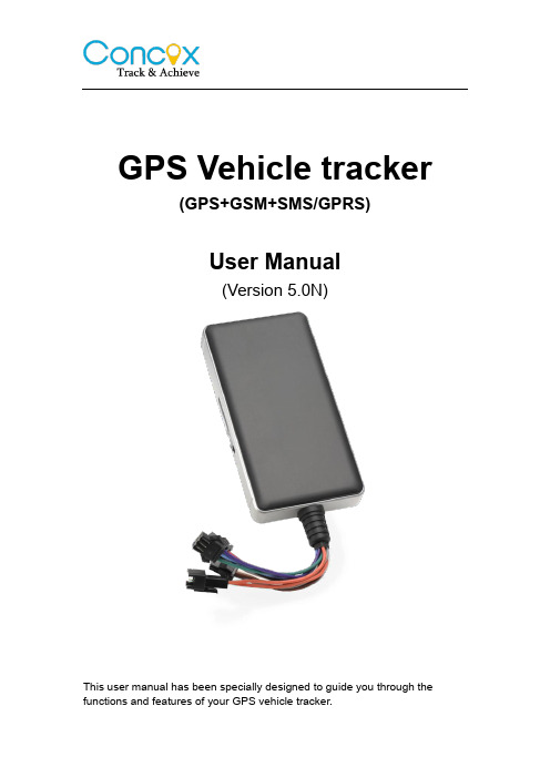
GPS Vehicle tracker(GPS+GSM+SMS/GPRS)User Manual(Version 5.0N)This user manual has been specially designed to guide you through the functions and features of your GPS vehicle tracker.1. Accessories:▶Device▶Power cord▶Relay▶Microphone▶SOS alarm cable & button▶User Manual2. SpecificationsDimension 106(L) x 54(W) x 16(H) mm Weight 96gBackup Battery 450mAh / 3.7VOperation Temperature-25℃-60℃Humidity 5% - 95%Standby Time 60hoursGSM Frequencies 850/900/1800/1900 MHz GPRS Class 12GPS Channel 20GPS Sensitivity -159dBmAcquisition Sensitivity -144dBmPosition Accuracy 10mTTFF (Open Sky)Cold Start: <38s Warm Start:<15s Hot Start:<2sGSM/GPS Antenna Built-in designLED Indicator GSM-green, GPS-blue, Power-redData Transmit TCP, SMSGeo-fence View any existing Geo-fence in the mapSpeeding Alarm Report when speeds higher than the pre-set value. Low Power Alarm Alarm when backup battery is running outNon-movement Detection Movement alarm based on built-in 3D motion sensor Mileage Report Track by time/distance intervalRemote Control Cut off petrol/electricity3. LED IndicationsGPS LED Indicator - BlueFlashing (interval 0.1s) Searching GPS signalSolid blue GPS fixOFF No GPS fix or initializingGSM LED Indicator - GreenQuick flashing (interval 0.1s) GSM initializingSlow flashing (flash 0.1s every 2s) Receive GSM signal normally Solid green Connected to GSM network OFF No GSM signalPower Status - RedFlashing (interval 0.1s) Low batterySlow flashing (interval 0.2s) Full chargeSlow flashing (flash 0.1s every 2s) Normal operatingSolid Red ChargingOFF Low battery/Power offIgnition detection indication: three LED indicators take turns flashing.4. Getting StartedPlease follow below instructions for ensuring safe and correct use.4.1 Install the SIM cardPlace the SIM card into the device with the gold-colored side facing down.Note: Make sure there is enough credit on the SIM card. If you will be using the GPRS function, you should pay attention to the current SIM card GPRS charge.4.2 Install the deviceYou need to choose somewhere that it won't be found, because the whole point of fitting covert GPS vehicle tracker is the secrecy element.Installation please refers to below picture.NOTE:1. Any high power devices such as reversing radar, anti-theft device or communication equipment would affect the signal of the device.2. All metallic cases of the windshield will attenuate the signal on the tracking device. It’s simply due to the shielding effects of the metal compound of the case.4.3 Wiring configurationLine No. Specification Color Instruction1. 2 Keypod Orange / Orange Connect to SOS button3. 4 MIC-,MIC+ Black / Red Connect to Microphone5 TX Green Sending data (TX) / backup6 RX White Receiving data (RX) / backup7 GND Black Ground wire8 MOTOR Yellow Connect to relay control line9 ACC White Connect to ACC ignition10 V- Black(thick) Negative side of 12V/24Vcar storage battery.11 V+ Red(thick)Notes of the relay wiringThe relay wiring of pump: oil connectors of both ends are a fine white line (85) and a fine yellow line (86). The fine white line (85) is connected to vehicle positive power (+12V). The fine yellow line is connected to the device relay control line.Cut off the positive connection line of the pump; then connect in series to the relay N.C. contact (thick green line 87a) and the other end to relay COM contact (thick green line 30).4.4 Device wiring diagramPlease choose the right relay (12V-standard / 24V-optional) for the proper installation. 4.5 Power/ACC/Tele-cutoff(petrol/electricity) control line (4 pin) 1. Your device comes with a power cord and is designed to use only manufacturer-specified original device. The red line is positive while the black one is negative (the side should not be connect with ground wire).2. The ACC line (white) connects to ACC switch of the vehicle. Please be sure to connect the ACC line; otherwise the device will enter ignition detectionstatus when disconnect the ACC line. If you don’t need to anti-theft temporarily, just connect the ACC line to the positive side in parallel.3. Tele-cutoff (petrol/ electricity) control line (yellow) is connected to pin 86 of the Tele-cutoff (petrol/ electricity) relay (equal to the yellow line of the relay socket).4. USB cable (3 pin)Firmware updating interface/expanded function to reserve space.5. MIC line (2 pin)Externally connect to microphone for voice monitoring function.6. SOS line (2 pin)Externally connect to SOS switch for SOS function.5. Quick Operation InstructionsOperation Tips: To properly use the device, common parameters should be set before initial use. This can be done by using the parameter editor or by sending SMS commands to the device. (“,”should be English comma and no space before and after the comma)5.1 APN settingTo connect default platform , please send the SMS command below:APN command format: APN,APN's Name#E.g: APN,internet# (“internet” is the APN of carrier)The device will reply “OK” if setting successfully.Note: The APN of some countries have user name and password, you may need to send SMS command as following:APN,APN name,user name,password#E.g: APN,internet,CLIENTE,AMENA#5.2 DNS settingTo connect other platform, please send the two SMS commands bleow: Command format:SERVER,1,DNS,Port,0#E.g:SERVER, 1,,8841,0#It will reply “OK” after set successfully.5.3 ON /OFF GPRSWhen you want to disable GPRS, you can SMS command to the SIM card number which used in the device.Command format:GPRS ON:GPRSON,1#GPRS OFF:GPRSON,0#It will reply “OK” after set successfully.5.4 Add specific numberSMS command to the device to set the SOS number.SOS,A,No.1,No.2,No.3#“A” means to add new numbers, for example:SOS,A,135****5991,135****5992,135****5993#If there is only one SOS number, you can appoint a specific number as SOS number. And the null means no adding.For example:SOS,A,135****5991#means to set the first number as SOS number SOS,A,,135****5992#means to set the second number as SOS number SOS,A,,,135****5993#means to set the third number as SOS numberIf set successfully, there is a “success” reply SMS.5.5 Delete specific numberBefore deleting specific number, please check its corresponding code. For the code, please SMS “PARAM#” to the device.SMS command to the device to delete the number.SOS,D,serial NO.1,serial NO.2,serial NO.3#“D” means to delete the number, for example:SOS,D,1# means to delete the first numberSOS,D,3# means to delete the third numberIf you want to delete more than one numbers, you can send this command: SOS,D,1,3# means to delete the first and third numbers.If you forget serial number of the mobile number you want delete, you can send this command:SOS,D,mobile number# means to delete the mobile number directly.For example:SOS,D,135****2360#meanstodeletethe135********directly.After deleting the SOS number, it will receive “Delete number 135XXXXXXXX success! specific number total 2” for successful deleting of the specific number.5.6 Set the center numberIf you want to cut off/restore oil by SMS command, you have to set a centernumber firstly. Only the center number can send the cut off/restore oil command to the device. You can set your own mobile number as center number.The command for setting center number is:CENTER,A,mobile number#Forexample:CENTER,A,159****3401#If set successfully, there is an “OK” reply message.NOTE:Only the SOS number can be used to set center number successfully.5.7 Delete the center numberSMS command to the device to delete the center number.The command is:CENTER,D#For example:CENTER,D#If set successfully, there is an “OK” reply SMS.NOTE:Only the SOS number can be used to delete center number successfully.Only SOS phone number can send this command successfully to set the center number. There is only one center number can be set.5.8 Check parameter settingSend command to the terminal, you can check the parameter setting. Command format: PARAM#e.g.: PARAM# Information replied:IMEI: 353419032348877 ---IMEI number of the device;Timer: 10,10; ---GPS data uploading Interval;SENDS:5; --- the GPS working time when ACC is OFF;SOS:159****3401;---SOSnumbers,maximum3SOSnumberscanbeset and used for alarm and monitoring;CenterNumber:159****3401;---only1centernumbercanbesetandused for cutting off /restoring oil command;Sensorset:10,1,5,180 --- detect 5 vibrations in 10s; the alarm delay is 180s; Defense time: 10; --- the defense delay is 10 minute;TimeZone:E,8,0; --- set time zone; default as E8.The replied information contains IMEI number, GPS data uploading interval, SENDS, SOS, center number, sensor set time interval, defense time and time zone.5.9 Check GPRS parametersSMS command format:GPRSSET#Eg:GPRSSET#Reply message:GPRS:ON //GPRS on/off status// Currently use APN:,,; //APN setting information// Server:1,,8841,0; //platform information// URL:/maps?q=; //preset web link setting information // 5.10 GPS data uploading intervalThe default sending interval is 10,10. It means when ACC ON ,the device will upload positioning data to platform server every 10s.when ACC OFF ,the device will upload positioning data to platform server every 10s.Users can modify sending interval by SMS“TIMER,time1(seconds), time2(seconds)”The time1&time2 ranges from 10-18000sFor example:TIMER,10,20#It means when ACC ON ,the device will upload positioning data to platform server every 10s.when ACC OFF ,the device will upload positioning data to platform server every 20s.5.11 Sensor alarm time settingWhen the vehicle power is off and ACC is in low-level, if ACC is off over 10 minutes, the device will enter sensor alarm state. In this case, if the vehicle vibrates for a few times, it will activate the vibration alarm system. If the vehicle battery is still not on (ACC is in low level) after 3 minutes, the device will start vibration alarm.SMS format: “DEFENSE,TIME(minutes)#” The time ranges from 1 to 60 mins.For example: DEFENSE,15#. It means when ACC is in low level for 15mins, it will enter sensor alarm status (vehicle power is off)NOTE:1. Preset SOS numbers when send SMS alarm messages and calls2. If there is no need for vibration alarm, please SMS SENSOR,0# to close it.5.12 Restore to factory settingSMS command format: “FACTORY#” to set all parameter to default factory value. Once received “OK”, it succeeds.5.13 Reboot deviceWhen there is something wrong with the link of GPRS, e.g., The parameter setting of the device is correct, but you can't track the car on the platform. At this moment you can send a command to the device to reboot the device. The format is: RESET#After receiving this command, the device will reboot after 1mins.6. Operation of device6.1 Power on/ Power offPower on: Once insert a valid SIM card and connect all the wires, turn on the device, then Power LED will flash first, During signal searching process, GSM and GPS LED will flash. Once GPS LED keeps solid light, it means the device has been located and it starts to work.Power off: Just turn off the power switch.The device will begin to upload positioning data to server once inserting a valid SIM card and power on. During the working time, it can upload data to server every 10 seconds.6.2 Check location1. Via SMS1.1 SMS “WHERE#”, to the SIM number of device. The device will send a location message automatically. You can get the coordinates. If the device does not search any information of location, it will send “No data” to the cell phone.Example:Lat:N22.571285,Lon:E113.877115,Course:42.20,Speed:0.0740,DateTime:10-11-23 22:28:511.2 SMS “URL#”, to the SIM number of device. The device will send a location Google Map link. If the device does not search any information of location, it will send “No data” to the cell phone.Example:<Date Time:10-11-23 23:42:51> /maps?q=N22.571490,E113.8771032. Via platformGo to the platform website offered by dealers to check your vehicle location.6.3 SOS alarmIn emergent case, press SOS for 3s to activate SOS alarm. Then the device will send SOS SMS to preset specific numbers and then dial the numbers in circles until the call is picked up. At the meantime, the device will upload SOS alarm data to the server. And it will send:SOS Alarm! <DateTime:11-06-17 14:53:06>,/maps?q=N22576713,E113.916585Note: The specific numbers should be preset, just refer to 6.46.4 Wire cut-off alarmWhen the electricity supply of device is cut off, it will activate cut-off alarm. In this case, the device will send related SMS to the specific numbers and dial the numbers in circles. If nobody answers, the call just keeps 3 loops at most. At the meantime, the device will upload SOS alarm data to the server. And it will send:Cut Power!<Date Time:11-06-17 14:53:06>,/maps?q=N22576713,E113.916585Note: The specific numbers should be preset, just refer to 6.46.5 Low battery alarmWhen the device is only working with battery, once the internal voltage of battery is less than 3.7V, device will send low battery alarm sms to specific number and alarm on platform.Low battery alarm sms content example: “Attentionbattery too low, please charge.” Which means the battery is to low, to inform user charging it i n time. Note: The specific numbers should be preset, just refer to 6.46.6 Vibration alarmThe vibration alarm function is off by default. To activate this function, please send the following command: SENALM, ON#. The alarm will be sent to both the service platform and SOS numbers.When vehicle power is off, ACC status is low, and if the lead time of low ACC is more than 10 minutes (settable), device will activate security alarm. When the security alarm is on, once the vehicle vibrates for several times, the alarm will be activated; in the next 3 minutes, if vehicle power is still off(ACC status is low), device will start alarm. At this time, it will send alarm message to the service platform with the latitude and longitude, while the platform will reply the Chinese address. Then the terminal will send vibration alarm message to SOS numbers with the Chinese address, and call the SOS numbers in cycle. If nobody answers, it will stop calling after 3 loops.If the Chinese address can not be acquired for certain reason, the terminal will send a message with the website link to the SOS numbers.e.g.:Sensor Alarm!<11-23 14:53>,/maps?q=N22576713,E113.916585Note:1.The SOS numbers should be preset.2.Send “SEN ALM, OFF#” to turn off the vibration alarm.6.7 Voice monitoringWhen the special number cell phone dial device, ringing for 10 seconds, it will enter voice monitoring status. At this time, caller can monitoring the sound in vehicle. Incoming call from non special number will not activate voice monitoring function.Note:To realize this function, please set special number beforehand.The SIM card put into the device should be equipped with caller identification.6.8 Oil cut-off1. Via platformSend oil cut-off command on platform. To make sure the security of vehicle, tracker can only indicate to cut off oil when GPS is in valid position status, and the speed is less than 20KM/H or in static. Platform account password is needed when sending oil cut off command.2. Via SMSFirstly, you should set a center number. Please refer to 6.6.Only center number can send the command to the device to cut off and restore oil.The format is: RELAY,1#After the command is carried out, it will reply “Cut off the fuel supply: Success! Speed:0 Km/h”. If the command didn't carry out, it will reply the reason about fail to carry out.Note: To ensure the safety of the driver and the car, this command is valid only under two conditions: the GPS is located; the speed is less than 20km/h 6.9 Restoring Oil1. Via platformWhen the alarm is off, sending recover oil commands manually. Device will restore oil supplying, and vehicle will work normally again.Platform account password is needed when sending oil cut off command.2. Via SMSOnly center number can send the command to the device to restore oil.The format is: RELAY,0#After the command is carried out, it will receive “Restore fuel supply:Success!”6.10 Over speed AlarmWhen the car is moving over a limited speed in average in a limited time period, then the device will send over speed alarm SMS to user.To turn on the over speed function, please send below SMS command: SPEED,ON/OFF,Time,Limited speed,uploading mode#Speed alarm switch:ON/OFF default:OFFTime range (seconds):5-600s(default as 20s)Limited speed range(km/h):1-255km/h. default:100Mode:0/1. default:1 way of alarming,0 means GPRS only,1 meansSMS+GPRSExample:SPEED,ON,20,100,1#Means when the car is moving over 100km/h in average in 20 seconds,the device will send over speed alarm to user7.Web based tracking online activationThe GPRS web based tracking platform allows real time tracking with the latest Google maps. There is also a playback feature that allows you to view where the vehicle has been for up to 30 days in the past making it ideal for fleet management.8.Trouble shootingIf you are having trouble with your device, try these troubleshooting procedures before contacting a service professional.Problems Causes SolutionsFail to connect platform The fuse blows Replace the fuse ACC ignition disconnected Turn on ACC with keyFail to connect network Wrong installation of SIMcardCheck SIM card installation(Refer to 4.1 Install SIM card) Filth on the SIM card ironsurface.Clean itUseless SIM Contact internet serviceproviderImproper installation Check installation of device(Refer to 4.2 Install the device) Beyond GSM service area Use it in effective GSM serviceoffer areaBad signal Try again in a better signalareaFail to charge The voltage is unsuitable Connect with power withsuitable voltage Improper connection Check connection withcharger1. The warranty is valid only when the warranty card is properly completed, and upon presentation of the proof of purchase consisting of original invoice indicating the date of purchase, model and serial No.of the product. Wereserve the right to refuse warranty if this information has been removed or changed after the original purchase of the product from the dealer.2. Our obligations are limited to repair of the defect or replacement the defective part or at its discretion replacement of the product itself.3. Warranty repairs must be carried out by our Authorized Service Centre. Warranty cover will be void, even if a repair has been attempted by any unauthorized service centre.4. Repair or replacement under the terms of this warranty does not provide right to extension or renewal of the warranty period.5. The warranty is not applicable to cases other than defects in material, design and workmanship.Maintenance RecordShenZhen Concox Information Technology CO.,LtdTel: +86 755 2912 1200Fax: +86 755 2912 1290E-mail:**************.Add: 4/F, Building B, Gaoxinqi Industrial Park,Liuxian 1st Road, No.67 Bao'an District, Shenzhen DateServiced by Product ModelIMEI NumberFaultDescriptionsCommentsWarranty instructions and service。
GT08 车载GPS追踪器用户手册说明书
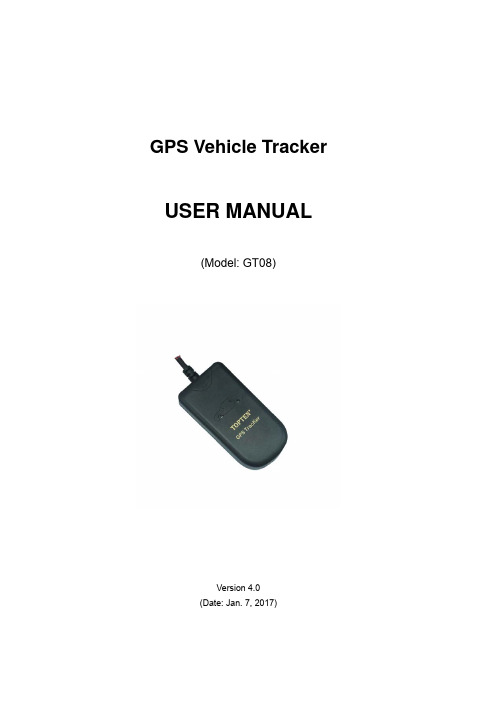
GPS Vehicle Tracker USER MANUAL(Model:GT08)Version4.0(Date:Jan.7,2017)CONTENT Preface (2)I.Features&Functions (3)II.How to Operate it (4)Authorize the Alarm-received Phone No (4)Arm/Disarm by Phone Calling (4)Check the Vehicle’s Status (5)Arm/Disarm the System by SMS (5)Check the location by Google Map’s URL (5)Check the Real Physical Address (6)Check the Real Physical Address Directly without Server (6)Check the Location by GSM Base Station Code (6)Change User Password (6)Stop the Car by SMS (6)Restore Car from Being Stopped (7)Monitor the V oice around the Car (7)Two-way Talking (7)Over-speed Alert (7)Speed Limiter (8)Power Save Mode (8)Fatigue Driving Alarm (8)Show the SMS Content in Languages (9)Define the SMS Content in other languages (9)Other SMS Command List (10)III.The Setting for GPRS Connection (13)IV.Snap Photo&Monitor via MMS/Email/Platform (14)V.Alarm Types (16)VI.Installation (17)VII.Specifications (19)VIII.FAQs&Troubleshooting (19)IX.Maintenance (20)PrefaceGT08GPS Vehicle tracker is the most advanced&cost-effective solution for vehicle security,real-time tracking&fleet management.It has the following unique functions:✧Support wireless immobilizer;✧Fuel leaking alarm,speed limiter&fatigue driving alarm;✧It is integration with GPS tracker+Car alarmRead it Firstly:Please read this manual thoroughly before you use the device;please keep it for future reference.Attention:(1)Please keep the device away from heavy water,high temperature,heavy dust or strong magnetism.(2)Please prepare a valid GSM SIM card in advance.(3)For safety,please keep the SIM number of your tracker in secretWarning:We strongly suggest user let the professional car electrician to install the system.I.Features&Functions1.Industrial design with high performance ARM7process2.Track on command or by time interval or by distance;3.Arm/disarm by SMS,phone call;4.Check the car’s real physical address(such as city name,street name..);5.Track by mobile SMS to get the latitude,longitude,speed,direction&odometer etc.6.Check the location directly by the Google map’s URL;7.Over-speed alert,Geo-fence alert,movement alarm;8.Snap photo and send out via MMS&Email when there is SOS alarm,ACCOn alarm or door open alarm,snap the photo via platform(optional);9.Speed limiter,when the speed is over limitation,the siren will sound to warndriver&relay will response to slow down the car automatically;10.Crash alarm,when there is crash&it can detect it automatically;(optional)11.Fatigue driving alarm,if continuous driving time is over the limitation,thealert will be triggered;12.Check the coordinates via LBS,even there is no any GPS signal..13.Support voice monitoring&2-way talking;14.Cut off engine to stop the car safely by SMS/GPRS;15.Trace optimization when vehicles turns a corner;16.Built-in shock sensor for power saving&triggering alarm17.Power failure alarm,with built-in rechargeable backup battery;18.SOS alarm(optional);19.Support analog input for fuel/temperature monitoring,fuel loss alarm;20.I/O:4digital inputs,1analog inputs&1digital outputs;21.There are3types of working mode for power saving flexibly.22.8M-bit offline data logger,it can store up to9,090waypoints.23.SMS content in multi-languages(English,Arabic,Spanish,Portuguese).II.How to Operate itThe default user password is111111.If the user password is changed,user should send the SMS command withXXX is the control code,all the letters must be capital letters or in small letters,command with mixed capital letter&small letter is not recognized by systemAuthorize the Alarm-received Phone No.SMS command:111111*10Mobile#1*20Mobile#2*In case of alarm,if user wants to get the alarm SMS from the tracker,he/she needs send the following SMS to program the tracker firstly,otherwise,the alert information can't be received correctly.Example:User sends the SMS111111*1013922713571*2013711189059*to the tracker’s SIM card number,if there is any alarm,system will send SMS to both of these two mobiles.In case of SOS alarm,the system will only send alarm to the mobile#2Arm/Disarm by Phone CallingUser could also use the1st alarm-received mobile phone to call the tracker’s SIM card number,so as to arm/disarm the system.Arm:After hearing several ring tones,if the systems hang up the call automatically,and call back you,it means that the system is armed.Disarm:After hearing several ring tones,if the system hangs up the call automatically,and don’t call back you,it means that the system is disarmed.Note:(1)There is no communication fee for this operation,it is a very convenient way to arm&disarm the system.(2)The SIM card inside the device must have the function of Caller ID Display.(3)Only the1st alarm-received mobile phone can realize this function.Check the Vehicle’s StatusSMS command:111111CHK(or111111chk)This instruction is used to inquiry the vehicle’s location&system’s status.The system will send back the SMS,includes the similar information,such as“Armed……”User could also use the2nd alarm-received mobile phone to call the tracker’s SIM card number,the tracker will hand up the calling&send back the location directly.Arm/Disarm the System by SMSSMS command:111111ARM(or111111arm)This SMS instruction is used to arm the systemSMS command:111111DSM(or111111dsm)This command is used to disarm the system&stop sending alert SMS.Check the location by Google Map’s URLSMS command:111111MAP(or111111map)Upon receiving the SMS command,the tracker will automatically send back the SMS including the Google map’s URL,user can use smart phone(GPRS data service is enabled)to open the URL link,the car’s location will be showed on the Google map.Check the Real Physical AddressSMS command:111111ADD(or111111add)When user sends this SMS command to the tracker,the tracker will automatically send back the car’s real physical address(such as city name,street name)to your mobile by SMS.(it need server's support for address translation).Check the Real Physical Address Directly without ServerSMS command:111111DDD(or111111ddd)When user sends this SMS command to the tracker,the tracker will automatically send back the car’s real physical address(such as city name,street name)to your mobile by SMS.(Note:this function might not work with some operator's SIM card.it is just for test).Check the Location by GSM Base Station CodeSMS command:111111LOC(or111111loc)This instruction is used to check the location by GSM base station code. The tracker will send back the relative GPS coordinates which is translated by the GSM base station code.Change User PasswordSMS command:111111PSWnnnnnn(or111111pswnnnnnn)This instruction is used to change the user password.The length of the user’s password is3~ers are suggested to change to the new password in use.Example:User sends the SMS“111111PSW12345”to the system SIM card number,and gets the confirmed SMS“111111PSW12345”in3seconds.It means that the user password has been changed to12345.Remark:Please keep the password deep in mind if it is changed.Stop the Car by SMSSMS command:111111STP(or111111stp)This instruction is used to stop the car in safe condition.If the car's speed is higher than30KM/h,the car is stopped gradually by impulse control,if the car's speed is lower than30Km/h,the car is stopped immediately.Attention:It is very dangerous to stop the car when the vehicle is running at high speed.We do not take any responsibility to the consequence caused by this action.Restore Car from Being StoppedSMS command:111111RES(or111111res)It is used to restore the car to normal status after being stopped.Monitor the Voice around the CarSMS command:111111MONThis instruction is used to monitor the voice around the car.The SIM card inside the system pays for the communication fee.SMS command:111111MON!This instruction is used to monitor the voice around the car.The user’s telephone pays for the communication fee.Example:User uses the mobile137****2345to send111111MON!to the system, then use the mobile137****2345to call the tracker,it will be connected automatically,and user can monitor the voice around.Two-way TalkingSMS command:111111MON:P1*This instruction is used to program the phone number which is used for carrying out direct monitoring or talking always.P1is suggested as center phone number for easy communication with drivers.Example:111111MON:139****3571*Over-speed Alert111111SPD:X x is the speed in KM/H,maximum value is255M/H(For example:111111SPD:120,if the car speed is over120KM/H,it will send out warning alert by SMS/platform).111111SPD:0to disable the over-speed alert.It is the default setting.111111SPD:to check the setting of over-speed alert.Remark:this function is just for reference,because there might be some time delay or error in detecting the running car’s real speed by GPS.Default speed limitation is120KM/H.Speed LimiterAfter user sets the speed limitation by command111111SPD:X,if car is over speed,the car will be slowed down gradually.111111BUZ:3:X,(X=1,activate siren;X=0:deactivate siren;default=1)111111RLY:3:X,(X=1,activate relay;X=0:deactivate relay;default=1)Power Save ModeSMS command:111111PWR:XValue of X Actions Power consumption 0(default)Disable power save mode60mA 1Close GPRS connection48mA2Close GPRS connection,GPS module13mA After setting111111PWR:1(or2),if there is no vibration&SOS alarm, integration line is not triggered,and ACC is OFF,the tracker will go into power save mode after5minutes.Once there is vibration or SOS alarm,or integration line is triggered,or ACC is ON,the tracker will wake up from the power save mode immediately.Fatigue Driving AlarmWhen this function is activated,if the engine is turned on for a certain time, the siren will sound to warn the driver.The SMS command:111111TIR:1:X,(with,at the end)X:is time in minutes(default:X=180minutes,maximum:65535minutes) Example:111111TIR:1:120,Show the SMS Content in Languages.SMS command:111111LNG:Xit is used to define the SMS content in different languages.X=0,English;X=1,Chinese;X=2,Arabic;X=3,Portuguese;X=4,Spanish;(Default setting:X=0,English) Define the SMS Content in other languagesStep1:choose the language mode such as:111111LNG:4to change to Spanish language firstly.Step2:Define your own text by the following command:111111TXT:nn:str!nn:str!nn:str!nn:str!nn:str!nn:str!Remarks:(1)6pieces of strings can be defined in one command.(2)nn:2bits,range:01~18(3)the number of letters in each str.can't be more than8(4)the character(.),(.),(!)can't be showed in str.Example:111111TXT:09:vibración!is to define the alarm text in Spanish when the shock sensor is triggerednn Meaning of Str.01Arm02Disarm03Power failure alert04SOS alert(in1)05Engine ON alert(in4)06Vibration alert07Stop the car(out1)08Restore the car(out1)09Over-speed alert10Original alarm's triggering(in5)11Geo-fence alert12Movement alert13The vehicle can't be stopped14Crash alert15Car door open alert(in3)16Broken line alert(in2)17Fuel loss alert18Un-defineOther SMS Command ListNote:******is user’s password and the default password is111111.The tracker will only accept commands with the correct password.III.The Setting for GPRS ConnectionThe GPRS setting is necessary for using the following2functions:(1)Check the car’s real physical address by send111111ADD(2)Online tracking service by web-based tracking platformSMS format:111111WWW:IPN:X;COM:X;APN:apn,user,password;RPT:X;SLP:X;RUN:X;⏹IDN:The tracker’s ID,it is the last14digits of IMEI which can't bechanged.⏹IPN:The IP address or domain name of the GPRS server⏹COM:The communication port for the GPRS server⏹APN:The Access Point Name for the GSM SIM card.⏹RPT:The interval for the uploading GPRS packet(Unit:sec.)⏹SLP:The interval for uploading GPRS packet when car is parked(Engine is OFF and no vibration).(unit:sec.);⏹RUN:GPRS connection setting.0=close,1=TCP,2=UDP.⏹IDN:The tracker’s ID,it is the last14digits of IMEI which can't bechanged.Example,if server is:,TCP port is8500,APN is web.gprs,,apn user:web,apn password:web,time interval is60 seconds,Then the command is:111111WWW:IPN:;COM:8500;APN:, web,web;RPT:60;RUN:1;User can send one or more options at the same SMS commands,such as:✧111111WWW:IPN:X;COM:X;This is to set the server’s address and port separately.Example:111111WWW:IPN:;COM:8500;✧111111WWW:APN:X;This is to set the APN(access point name).Please use“,”to separate the APN,APN username&APN password.Example:111111WWW:APN:,web,web;✧111111WWW:RPT:X;This is to set the upload time interval.The unit is second,the minimum value is10seconds.The default setting is60Example:111111WWW:RPT:60;(Upload time interval is every60s)✧111111WWW:RUN:X;X=0;is to close down the GPRS;X=1;is to open the GPRS via TCPX=2;is to open the GPRS via UDPEg:111111WWW:RUN:1;(Open the TCP connection)✧111111WWW:You can send111111WWW:to check the GPRS settings.Default GPRS SettingThe default GPRS setting is:✧IPN:,COM:8500✧APN:cmnet RPT:30seconds✧SLP:0RUN:1IV.Snap Photo&Monitor via MMS/Email/Platform It is the optional function for3G version,the extra serial camera is needed.✧Snap the Photo via MMS111111MMS:to get the Photo via MMSTo realize this function,user must do the correct MMS settings firstly.✧MMS Setting for SnappingThe MMS setting is different from GPRS setting,the SMS command is as following:✧X:MMSC server URL;✧Y:The IP of MMS proxy✧Z:MMS_APN,user,Password.✧N:The Port of MMS proxyFor more information about the MMS settingparameters of worldwide GSM operators,please searchby Google or refer to this link:/mobile-operator.mmsc-settingsExample:(for Nigeria MTN SIM card)The correct setting SMS command is:111111MMS:SVR:http://10.199.212.8/servlets/mms;PRX:10.199.212.2;APN:web.g,web,web;COM:8080;✧Set the Way of Sending PhotoSMS command:111111PIC:1:X,2:X,3:X,4:X,5:X,6:X,7:X,8:X,9:X,(with,at the end)X=0,means Disable;X=1,means Enable1:X,engine on(input4);2:X,car door open(input3);3:X,over-speed;4:X, vibration;5:X,movement alarm;6:X,fatigue driving alarm;7:X,broken line alarm(Input2);8:X;original alarm's triggering(input5);9:X;SOS(Example:111111pic:1:1,2:1,9:1,)default setting as1.SMS command:111111SEE:6:X,7:Y,8:Z,(with,at the end)6:X,X=1,send photo via MMS to1st alarm-received no.;X=0,disable.7:Y,Y=1,send photo via MMS to2nd alarm-received no;Y=0,disable.8:Z,Z=1,send photo to email box;Z=0,disable.(Example:111111SEE:6:1,7:1:8:1,)✧Set the Email to Receive the PhotoSMS command:111111BOX:Email(Example:111111BOX:*******************)V.Alarm TypesVibration AlarmIn arming status,if the car is vibrated,it will send out alarm SMS.Power Failure AlarmIn arming status,if the battery is cut off,it will send out alarm SMS.Engine ON AlarmIn arming status,if the car’s engine is ON,it will send out alarm SMS and call the preset phone.Movement AlarmIn arming status,the movement alert is enabled automatically.Once the car moves away from the parking point for100meters,it will it will send out alarm SMS and call the preset phone.Geo-Fence AlarmOnce the Geo-fence is activated,if the car oversteps the boundary,it will send out alarm SMS.Over-speed AlarmIf the car runs over the speed limitation continuously for3minutes,it will send out alarm SMS.SOS AlarmIn any condition,if the SOS button is pressed,it will trigger the SOS alarm.(NOTE:the SOS alarm will only be sent to the2nd phone,the3rd phone number&the GPRS tracking center,the other alarms will send to all the preset phones&GPRS tracking center.)Crash Alarm(optional)If there is crash,the crash sensor will detect it and send out alarm.Fatigue AlarmIf the accumulated time of engine on is over the setting,the sire will sound to warn the driver.Fuel loss Alarm(optional)When the engine is OFF,if the fuel level is down,it will trigger the alarm.VI.InstallationInstallation Steps:(1)Please read the manual carefully before installation.Please prepare a validGSM SIM card with Caller ID Display&GPRS function;(2)Please push the front cover according to the direction;(3)Insert the valid GSM SIM card,then turn on the backup battery switch;(4)Close the cover,and fix the main unit tightly with the wiring harness at thecorrect place,please make sure that the side with GPS antenna is placed upside to sky,please make sure to install the main unit at broad place so that it can receive GPS signal well.For motorcycle,it is better to install inside the head bulb light where there is power supply and water proof.For vehicle,it is better to install inside the upper rim of the driving room or inside the dashboard.The recommend installation place is showed in the following picture:For motorcycle For vehicle(5)Do the wring connection according to the diagram;(6)Call the SIM card,to check if rings,if not,then check the power supply andthe change the place of installation;(7)If it rings when calling the SIM card,then send SMS to the tracker to checkthe GPS coordinate,if the GPS location is not correct,then fix the main unit to other place so that it can receive better GPS signal.(8)IMPORTANT:The side with GPSantenna must be placed upside to thesky and kept away from the metalmaterials,otherwise,it can’t get GPSsignal well.VII.SpecificationsVIII.FAQs&Troubleshooting(2)Low power,please use outside power supply to power on the unit to testI can not get the alarm message (1)The SIM card inside the device has no credit;(2)The Alert-received mobile number is not programmed correctly,or the SMS command is not in correct format;(3)The mailbox of the user’s mobile is full;I can not get the correct GPS coordinates or the location is wrong (1)Please make sure there is no metal obstacles above the tracker.Please place the side with GPS antenna upside to the sky;(2)Please check it at broad place;(3)Please check if the GPS LED flash once every3seconds;place the tracker to other place, so as to make sure that it can receive the GPS siganl well(4)In cloudy condition,it is a little hard to get the GPS signal,and the GPS coordinate might have some errors.Tracker fails to connect to server by GPRS (1)The SIM card must be activated with GPRSfunction;(2)Do the correct setting for GPRS connectionIX.Maintenance✧The installation must be done by the professionals.Illegal disassemblywithout permission might cause invalidity of warranty.✧Please keep the device in dry place✧When the car is inside buildings,cave,tunnel,or very close to tall buildings,the GPS/GSM signal may not work well and the system may fail to work at that moment.✧Please check the balance of the tracker’s SIM card periodically.✧The backup battery can only work for a certain time once power-off.FCC Information and CopyrightThis equipment has been tested and found to comply with the limits for a Class B digital device, pursuant to part15of the FCC Rules.These limits are designed to provide reasonable protection against harmful interference in a residential installation.This equipment generates,uses and can radiate radio frequency energy and,if not installed and used in accordance with the instructions,may cause harmful interferenceto radio communications.However,there is no guarantee that interference will not occur in a particular installation.If this equipment doescause harmful interference to radio or television reception,which can be determined by turning the equipment off and on,the user isencouraged to try to correct the interference by one or more of the following measures:—Reorient or relocate the receiving antenna.—Increase the separation between the equipment and receiver.—Connect the equipment into an outlet on a circuit different from that to which the receiver is connected.—Consult the dealer or an experienced radio/TV technician for help.This device complies with part 15 of the FCC Rules. Operation is subject to the condition that this device does not cause harmful interferencechanges or modifications not expressly approved by the party responsible for compliance could void the user's authority to operate the equipment.This equipment complies with FCC radiation exposure limits set forth for an uncontrolled environment.This equipment should be installed and operated with minimum distance20cm between the radiator&your body.This transmitter must not be co-located or operating in conjunction with any other antenna or transmitter.。
GPS车辆追踪器说明书

GPS Vehicle tracker(GPS+GSM+SMS/GPRS)GT06 User Manual(Version 3.2)Thank you for purchasing the tracker. This manual shows how to operate the device smoothly and correctly. Make sure to read this manual carefully before using this product. Please note that specification and information are subject to changes without prior notice in this manual. Any change will be integrated in the latest release. The manufacturer assumes no responsibility for any errors or omissions in this document.1. SummaryWorking Based on existing GSM/GPRS network and GPS satellites, this product can locate and monitor any remote targets by SMS or internet.Overview of the characteristics:1.GSM 850/900/1800/1900MHZ.2.GPS position.3.Auto set APN.4.300Mah Battery inside, Power-Cut alarm.5.Motion detect, save GPRS flow.6.SOS Alarm.7.Shock Alarm.8.ACC Alarm.9.Speed Alarm10.Voice Surveillance.11.Voltage DC 9-50V.12.Enginee Cut off.2.Accessories:Power line:Relay:Microphone:SOS line:Manual3. Specs1).GSM:850/900/1800/1900MHZ2).GPRS: Class12, TCP/IP3).Working Voltage:9-50V DC4).Working current:≈22mA (12VDC)5).Working current:≈12mA (24VDC)6).GPS locating time:Cold start≈38s(Open sky) Warm start≈32sHot start≈2s(Open sky)7).GPS Precision:10m(2D RM)8).Working temperature:-20℃~+70℃9).Working humidity:20%~80%RH10).Measurement:98(L)×52(W)×16.5(H)mm4.Wire defined5.Device status indicators5.1 Connect DC 9-50V power supply and the red LED will light continuously.5.2 The blue LED light continuously when searching the GPS signals. When GPSposition,the blue LED flashing.5.3 The intermediate green LED (GSM signal state)GSM signal is normal, green LED flashing. No GSM signal, the blue LED light continuously.All LED will turn off after 5 minutes. When there is a new call, the LED will relight and turn off 5 minutes later.6.Installation6.1 Prepare for installation6.11 Product Check. Open the packing box and check the device‘s model and accessories.If the model is wrong or the accessories not complete, please contact the dealer.6.12 Choose SIM card. Please insert a SIM card to the device. Please take dealer’sadvice as reference.6.13 SIM card installation. Discharge the cover of the device and uncover the SIMcard holder. Then insert the SIM card and cover SIM card holder (as follows).6.14 Open the cover, Push the switch to make the battery working. Then Put back thefront cover and screw it up.6.15 Connect the device to the 9-50V power supply.6.16 Install the device in the hidden place of the car;The SIM card must be with GPRS function and enough deposit. If your SIM card need input PIN when power on, please cancel it.6.2 InstallationThe GPS tracker must be installed under professional personnel.Note:1) Please install the device in the hidden place as followings:Under Front windshield;In the front instrument panel;Under back windshield;2) Avoid being placed with signal radiators like reverse sensor ;3) The device has GSM antenna and GPS antenna inside. Please ensure thereceiving side of the device is face up and without metal cover.Note: The metal cover will lessen the receiving of GPS signals.6. The device connecting requirements.7. Device wiring requirements7.1The device power supply is DC 9-50V. The red line is positive pole while the black line is negative pole.7.2 The negative pole of power supply connects with ground or the metals. Please do not connect with other ground lines.7.3 When finishing the power supply wire connection, please make the plug of power supply to the device.8.The Device Working8.1Power on:Connecting to the power. Then the three LED indicators will light. Thedevice will upload the data to the online platform (the default intervalof uploading data is 15seconds). When the car is in static state for a longtime, the device will be in energy saving mode and it will be more smartand precise.8.2 Power off:Pull off the power plug then power off the device.er Settings9.1 SMS Commands instruction1)Center NumberText command Parameter SampleCENTER Add710#number#711#number# 710#135****5000# 711#138****8000#CENTER DelD01#D02# D01# D02#Command Description 1)Center number can control the oil and power and resumefactory settings2) Center number can receive the call and text of vibration alarm and over speeding alarm.3) SIM must display the income call number to controloil and power.4) Only 2 number can be center number.5) Change center number must resend the command.6)Add new center number by CETNER,A, and delete byCENTER,DCommandFeedbackSuccessful Setting:Add admin account 1 OK!2) View Center NumberText command Parameter SampleView 901# 901#CommandDescriptionThis directive is used to view Device Manager number.Command Feedback Successful Setting:Admin1: Admin2:3)Authorized Number SetText command Parameter SampleAuthorized Add 101# number #102# number #103# number #1:101#138****8000#2:102#12345678912#3:103#12345678912#Authorized Del D11#D12#D13#D11#D12#D13#Command Description 1) Authorization number for SMS control oil.2) only three numbers to set the authorization number3) change the authorization number needs to delete the previous numberCommand Feedback Successful Setting:Add Authorization account 1 OK!4) View Authorized NumberText command Parameter SampleViewauthorizedC10# C10#Command Description This directive is used to view the equipment authorization numberCommand FeedbackSuccessful Setting: Authorization 1: Authorization 2: Authorization 3:5)APN SettingText command Parameter SampleAPN Setting 802#username#pass1:802#intenet#123#123#word] 2: 802#internet#Command Description APN differs according to the local telecom operators. For example:APN request password,please refer to Sample 1,and Sample 2 for no password.CommandFeedbackSuccessful Setting:SET APN OK!6) Set ServerText command Parameter SampleSERVERParameter803#SERVER # port# 803#222.217.240.243#8011# View SERVER CIP# 1)CIP#Command Description Change the IP and port when move to a new server port:10~655351 is domain and 0 is IP;Command Successful Setting:set IP OK!Feedback7)Moving Time IntervalText command Parameter Sample TIMEERParametersetting730#uploading interval# 730#20#Command Description Time scope:0,10~60 seconds; 0,no data uploading;10~60,means time interval;the default value is 15 seconds!CommandFeedbackSuccessful Setting:SET TIMER OK!8)Static Time IntervalText command Parameter Sample STATIC SUP# time interval#SUP#5#Command Description Timescope:1~60 minutes;The device has3D transmission and the default time interval are 5 minutes.CommandFeedbackSuccessful Setting:SET STATIC TIME OK!9)Cancel the continuous uploadText command Parameter SampleNUP NUP# NUP#Command Description This command is used to cancel sending data to the platformIf need again to restore the upload , you need to send TIMEER Parameter setting.CommandFeedbackSET OK!10)Oil-CutText command Parameter SampleRELAYParameter1222# 222# cut off oil and power RELAYParameter2333# 333# recover oil and powerCommand Description 1)RELAY control the start and closeness of the relay2) Only the center number can operate.3)the device only cut off the oil circuit on the condition of the driving speed below 20KM/H or in static state.4)When send the command, the device will reply “please waiting “When the vehicle speed is over 20KM/H, the device will cut off the oil or the power when the speed below 20KM/H.Command Feedback Successful Setting:Fuel cut has already been completed OK!11)GMTText command Parameter Sample GMT801#location,time#801#E8#Command Description The default time zone is Beijing time. If time zone need revised, please operate according to the above command.CommandFeedbackSuccessful Setting:Set time zone ok!12)Vibration AlarmText command Parameter Sample Open Vibration Alarm911# 911# VIBRATION Parameter123#sensitivity#,alarming way#1) 123#2#3# Set intovibration alarm time V123#2#1) V123#2#2) V123#1#Cancel vibrationalarm456# 456#Command Description the sensitivity value of the vibration is from 1 to 5,1is the most sensitive and o is close. Alarming ways: 1, calling 2, texting, 3 calling and texting.Must set the center number and receiving number.Command Feedback set vibration alarm level,OK!13)Speed AlarmText command Parameter SampleSPEEDING Parameter SSA#120# alarmingway#11) SSA#120#2) SSA#150#3#Command Description The speed scope is form 60-220, if the speed is no this cope, the alarm is off.Alarming :1, calling 2, texting, 3 calling and texting.Must set the center number and receiving number. CommandFeedbackSuccessful Setting:set speeding alarm,OK!14)ACC AlarmText command Parameter SampleOpen ACCAlarm840#1# 840#1#Close ACCALARM840#0#Close ACC ALARM The speed scope is form 60-220, if the speed is no this cope, the alarm is off.Alarming :1, calling 2, texting, 3 calling and texting. Must set the center number and receiving number.CommandFeedbackSuccessful Setting:set speeding alarm,OK!15)ResetText command Parameter SampleRESET 930# 930#CommandDescriptionReset the deviceCommandFeedbackSuccessful Setting:Reset system, ok!16)FactoryText command Parameter Sample Parameter 940# 940#Command Description Restore the factory settingOnly center number can initial this functionFactory setting will recover to the original settingCommand Successful Setting:FACTORY OK!Feedback17)Language SettingText command Parameter SampleLANG Parameter LANG1#LANG0#LANG1# 1:CHINESE,LANG0#:ENGLISHCommand Description ;When check the location, it will reply the Chinese location in Chinese language setting; while reply the URL link when in English language setting.CommandFeedbackSuccessful Setting:SET LANG OK!18)PositionText command Parameter Samplecommand 988# 988#Command Check the longitude and altitude and otherDescription information of the deviceCommandFeedbackReply with longitude and altitude, speed and IMEL.19)Google LinkText command Parameter Samplecommand 666# 666#CommandDescriptionCheck the location link of Google mapCommand Feedback <Datetime:12-07-05 13:21:30>/maps?q=N22.540885,E113.9526520)VersionText command Parameter SampleVERSION V00# V00#Command The command is to check the software versionDescriptionCommand Feedback VERSION:XxxxBUILD:2012-07-05 10:1221)Param CheckText command Parameter Sample PARAM 886# 886#Command Description The command is to check the settings and the default parameter.Command Feedback IMEI:351190012535936APN : cmnetIP:IP and portTIMER: moving uploading interval STATIC: static uploading interval CENTER: center numberLANG: language(CN/EN)GMT: time zone (E/W8)22)Status CheckText command Parameter Sample STATUS 902# 902#Command Description The command is designed for checking the device’s working status.Command Feedback External power:ON/OFFGSM Signal:HIGH/MIDDLE/LOW GPS:FIXED/UNFIXED RELAYER:DISABLE/ENABLE Vibrate Warning:ON/OFF Pause:ON/OFF23)Monitor (Voice Surveillance)Text command Parameter SampleSSS# SSS# SSS#Command Description Using Command Send this command to the tracker’s number, the tracker will call back to admin number.CommandFeedback10.Trouble shooting10.1 The device is not online or offline on the web platform.10.1.1 First, please check the three LED working state. Ifpossible. You can call the device’s number to check.● If not connected, the device is out of signal. If the GSMsignals cannot reach your location, please drive to the open sky.z If reminding the device SIM card is out of deposit, please make deposit by the telecom operator.● If you can connect to the device when calling, the SIM card hasdeposited and please check with your operator for GPRS function. You also can check by searching the internet on your mobile phone.● If reminding the device is power off, please turn back the deviceand proceed as followings:a)Check if the red LED is in constant glow. If the LED is dark, pleasecheck the power connecting. If fuse is broken, please return the device to the seller.b)If the green GSM LED is not in constant glow, please check theinstallation of SIM card.10.1.2Please check the offline area in order to judge if the networkproblem of operators.10.2When GPS cannot receive the signals, please drive in the open skyand ensure there is no metal thins on the device.10.3 When the device cannot receive the GSM signal, please check theSIM card installation. If the GSM signals cannot reach your location (such as the basement), please drive to the open sky.。
GPS车载终端操作说明书

一、GPS终端定位系统安装接线图
二、安全注意事项
1、安装前,接上GPS和GSM天线,注意两根天线不要接反,扁扁长长的为GSM天线,正方型带磁铁的为GPS天线。
2、摆放GPS天线时,带磁铁的一面向下用双面胶贴好,GPS天线头的上方不能有金属物遮档,玻璃和塑料不会影响GPS信号的接收。
3、6P线定义:接上主机的电源线,红色接电源的正极,黑色的接电源的负极。
白色线为ACC感应线,其余的线为预留线,无需理会。
4、通上电以后观察两个指示灯的状态。
黄色灯与红色灯交替闪烁,说明设备定位通讯正常。
5、主机正常,固定好GPS主机,安装完成。
沃多仕 车辆GPS定位器 用户手册说明书
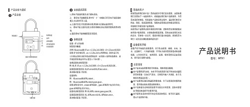
产品说明书产品安装与调试产品安装安装调试流程感谢您选用我们的产品!您的选择对于我们至关重要,这意味着我们又增加了一名新的用户。
希望通过我们的产品和服务,为您带来美好的体验。
也希望在产品的应用过程中,通过我们的官方网站,微信,各渠道销售商,客服电话等提出好的建议和意见,帮助我们不断完善产品和服务。
如果您在产品使用过程中遇到任何问题,请联系您当地经销商或按照客户服务流程,方便快捷的获取帮助。
您的支持是我们成长的动力,您的每一次认可,都是对我们最大的鼓励。
感谢有您与我们一起开启车辆位置服务新生活!注意事项设备使用声明尊敬的用户本产品在安装和使用时不能撞击、雨淋和高温曝晒。
本产品使用GPS定位,存在不可抗拒因素引起不能定位或通信异常的现象(比如天气恶劣、无线信号被人为屏蔽、处于无线信号覆盖盲区等)。
本产品使用GSM无线通信网络传输,为了达到更好的使用效果,请尽量安放在远离金属的地方。
本产品的部分功能需要监控平台配合才能实现,具体内容请参 照相关的监控平台使用手册。
本手册所涉及的内容可能会有更改的情况,恕不另行通知,请以产品实物为准。
设备严禁不按操作说明使用,对于私自拆卸、碰撞、充电、泡水、过温80℃、人为破坏故障、不可抗力损坏等因素造成的设备短路、工作时间不足、电池变形、漏液、爆炸等情况及连带损失,将不进行保修与赔偿。
参数设置电池电量蓝牙GPRS网络GPS定位状态开关锁状态充电接口解封卡RFID感应区1) 将电子锁锁杆解开,处于断电状态;2)掰开电子锁橡胶套,用中号”十”字螺丝刀打开电子锁后面的螺;3) 丝,此时打开上盖;4) 上盖打开后,可见到SIM卡座,将SIM卡正确安装好即可;5) 将电子锁上盖壳合好,注意拧紧螺丝,防止因此而影响其密封性能;6) 最后将电子锁的橡胶套还原套好;设置---IP工作参数短信指令编辑:示例:HL66556688:IP,45.112.204.250,3809,137****5678,0020说明: IP 命令标识符; 45.112.204.250 公网IP地址; 3809 端口号;137****2980本机号码或者终端号(必须是11位阿拉伯数字,若不想改变原终端号可以填写11个8代替);参数设置成功短信回复:例:HL:IP,IP,45.112.204.250,3809,137****5678,0020,OK。
TL-101车载GPS跟踪器说明书
注意: 检查设备的工作状况: a. 在安装好设备,放入 SIM 卡以及开始给设备供电之后,等待大约 1 分钟的时间。 b. 拨通设备内置 SIM 卡的号码,如果设备在 10 秒钟之后自动挂断, 则说明设备已开始工作。 c. 注意 GPS 信号指示灯,如果 GPS 信号指示灯持续闪亮,则说明 GPS 已经开始工作。 d. 关闭设备电源就可重新启动设备。 e. 任何情况下,如果设备被重新启动后须等待至少 1 分钟,才可以 重新接电使用。
GPS & GSM 车载定位器使用说明:
-2-
接口说明: 图 1:
图 2:
GPS & GSM 车载定位仪
GPS & GSM 车载定位仪
安装:
专业的汽车电子技术人员可以快速地完成该设备的安装。
简易安装提标
• 输入功率: 6-30 伏直流电 (内建极性保护– 该设备会在输 入电极端被反接时停止工作,不会受到任何损坏)
11. 输入和输出端口示意图1:
断电器 输 入 端 口 3 输 入 端 口 2 输 入 端 口 1
输出
(负触发) (负触发) (负触发)
接地线 输 入 端 口 3 输 入 端 口 2 输 入 端 口 1
(正触发) (正触发) (正触发)
当第一路输入端口被原车防盗器触发时,设备会自动发送短信如:
“INPUT1 ALARM!! + GPS 信息”至被授权手机号码。
9. 发送短信命令设置超速警报 短信内容:密码+J+ 速度 注意:如果设定速度限制为 200 公里/小时, 那么短信的内容应该 为:“123456J200”,当车辆行驶的速度超过 200 公里/小时的时候, 系 统会自动发送一条短信给被授权号码 A,其内容为“Overspeed! +GPS 信息”。
GPS监控系统使用说明书
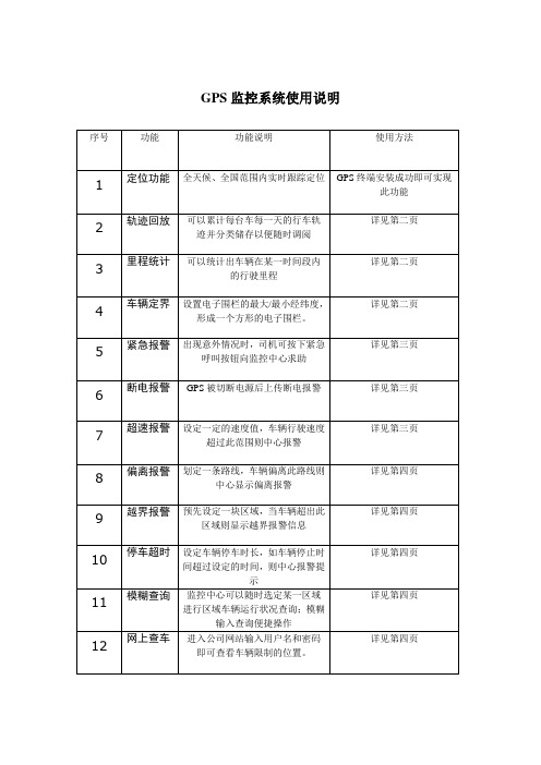
GPS监控系统使用说明序号功能功能说明使用方法1 定位功能全天候、全国范围内实时跟踪定位GPS终端安装成功即可实现此功能详见第二页2 轨迹回放可以累计每台车每一天的行车轨迹并分类储存以便随时调阅详见第二页3 里程统计可以统计出车辆在某一时间段内的行驶里程详见第二页4 车辆定界设置电子围栏的最大/最小经纬度,形成一个方形的电子围栏。
详见第三页5 紧急报警出现意外情况时,司机可按下紧急呼叫按钮向监控中心求助6 断电报警GPS被切断电源后上传断电报警详见第三页详见第三页7 超速报警设定一定的速度值,车辆行驶速度超过此范围则中心报警详见第四页8 偏离报警划定一条路线,车辆偏离此路线则中心显示偏离报警详见第四页9 越界报警预先设定一块区域,当车辆超出此区域则显示越界报警信息详见第四页10 停车超时设定车辆停车时长,如车辆停止时间超过设定的时间,则中心报警提示详见第四页11 模糊查询监控中心可以随时选定某一区域进行区域车辆运行状况查询;模糊输入查询便捷操作详见第四页12 网上查车进入公司网站输入用户名和密码即可查看车辆限制的位置。
2轨迹回放在客户端软件里选择目标车辆----点击历史数据----在下图中选择查询条件----完成后点击播放按钮播放轨迹。
3里程统计在客户端软件里选择远程设置按钮----选择目标车辆(必须目标车辆发动的情况下才可下发指令)----在配置参数里选择里程参数设置----里程信息选项里选择不清零----选择保存设置----确定----对目标车辆下发指令。
4 车辆界定在客户端软件里选择报警区域-----点击确定----选择工具对目标区域进行选定5 紧急报警在GPS终端上有个红色按钮,即紧急报警按钮。
6 断电报警在客户端软件里选择报警数据按钮----里面对各种报警都做了详细的分析。
7 超速报警在客户端软件里选择远程设置(注:需要在车辆发动的前提下才可以下发指令),设置好速度以后选择保存设置----点击确定。
全能型车载GPS应用手册
全能型车载机应用手册本手册假定您已经熟练掌握了我公司物流调度系列、物流调度系列、通用型等车载机的应用,以讲述全能型车载机与其他型号产品区别的方式介绍相应功能的注意事项。
如果您是第一次使用我公司产品,请参考以上相应系列、型号车载机的安装、使用手册,以及《gps车载设备协议(全文)规程》。
全能型车载机是目前我公司所有生产型号功能的集大成之型号,涵盖了GPRS型、新GPRS 型、GPRS增强型、通用型产品的所有功能,在通信协议上完全兼容。
一、全能型车载机增加的功能除了已有产品系列中的位置/状态回传,区域监控、速度监控、私家车防盗、道路检测、行车记录、疲劳驾驶、图片拍摄等等之外,全能型车载机增加了下列新功能:1、模拟量输入扩展到到10路。
2、增加4路数字量输出3、增加固定手机短信报警4、数据口改为RS232电平输出,且直接支持透明传输。
5、采用锂电池后备电源,待机时间达到8-10小时6、功耗大大减小,在GPS不休眠、无GPRS传输情况下,电源电流50mA@12V。
二、模拟量输入全能型车载机的模拟量输入扩展到到10路之多,分别是:1、模拟量0、1,与通用型车载机在接口方式、通信协议上完全兼容,但量程变为33.0V,Y模式变为Z模式(仅仅字头由“Y”变为“Z”,其他不变)。
2、模拟量2、3,分别由高电平传感器1、2输入线输入,即高电平传感器1、2不仅可以定性测量其上电平高低,还可定量测量其上的电压值。
3、模拟量4、5则分别由发动机、ACC输入线输入。
4、模拟量6、7分别通过遥控输入的设防、撤防端子输入。
为避免误触发引起设防、撤防,若需要使用模拟量6、7,请将S4命令中的Set2设置为bit6=0,即关闭掉遥控输入按键。
此时仍然可以通过手柄进行设防、撤防。
5、模拟量8、9的输入信号分别为电源电压和后备电池电压。
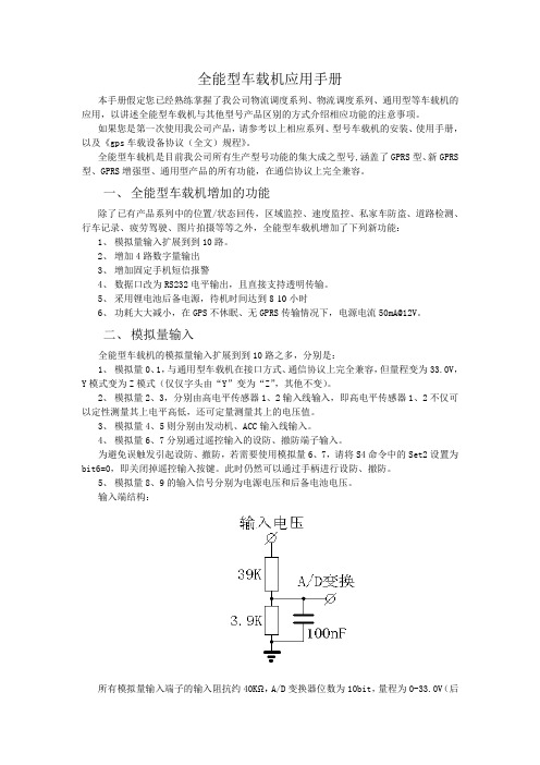
输入端结构:所有模拟量输入端子的输入阻抗约40KΩ,A/D变换器位数为10bit,量程为0-33.0V(后备电池的测量量程为14.7V),参考电压为3.00V,精度为1%。
GPS 车辆定位器用户手册说明书
User Manual(Version 2.1)1.AccessoriesThis user manual has been specially designed to guide you throughCharging cable (Standard)2.Specification3. Quick Operation InstructionsChange APN parameter by sending SMS “APN,666666,APN name#” and “SERVER,666666,1,,8821,0# ”to the device.3.1 Locate current position by GPRS/SMS3.2 GPS tracking platform:3.3 Track by time interval via GPRSSend SMS “TIMER,666666,,time(second)#” to device. 10s in minimum while 18000s(5 hours) in maximum.3.4 Change passwordThe default password is 666666. Send SMS “PASSWORD,old password (6 numbers),new password (6 numbers)#” to the device.3.5 Real-time Location Tracking via SMS3.5.1 Send SMS “WHERE,666666#” to the device, you will get the current location of the device.3.5.2 Send SMS “URL,666666#” to the device, you will get the URL of the current location by .4.My Device5. LED Indications6.Method of installation6.1 Preparation before installation1)Open the packing box to check whether the type of device is correct and whether the accessories are included.2)This product is a high-tech electronic device, installation should be undertaken by a professional.3)Please follow the following procedures to install your GT02A.During installation, there should be no power to the device.6.2 Installing SIM card: each GT02A need to insert a GSM SIM card. The SIM card used should be enabled for GPRS.1)Testing SIM card: to test SIM card, please install it into a normalGSM mobile and ensure it can send and receive SMS, and enables for GPRS.2)Installing SIM card:Remove the upper cover of device,insert SIM cardas shown then replace cover,lock the Shell With 3 bolts.6.3 Selecting installation place and fixing it.There are twokinds of installation: covert and non covert.If you need the covert installation, please refer installation to an auto electrical contractor.Note:1)To prevent theft of the GT02A,the device should be installed ascovertly as possible.2)Avoid placing the GT02A close to higher power electrical devices,such as reversing radar, anti-theft device or other vehiclecommunication equipment.3)The GT02A should be fixed into position with cable ties or widedouble-side tape.4)Your device has built-in GSM antenna and GPS antenna. During installation, please make sure the receiving side face is up, with no metal object above the device to interfere with GPS reception. The following places are suggested for installation:- Under the dash board below the front windshield;- In the parcel shelf in the rear;- In the front bumper( non-material face), please ensure the device cannot get wet;- Under the wiper version (non-metal), please ensure the device cannot get wet;Notice: If the windshield is pasted with metal thermal-protective coating, it may affect the performance of the device. In this case, please change the installation place after consulting the professional.5)Non Covert Installation,Firstly fix the device on the dash board below windshield.7. Cautions of device wiring7.1 The standard voltage is 9V-36V, the red wire is the positive, the black wire is the negative.7.2 Please connect the black wire to ground.7.3 After connecting the power cord, run the power cord plug to the device. After installation, supply power to device.7.4 Covert installation: car battery cord is standard, with 2A FUSE for short-circuit over current protection.7.5 Non covert installation: cigar lighter cord is optional, with 2A FUSE for short-circuit over current protection. Please contact your dealer if this mode is needed.8. Power on/ off8.1 The device will power on automatically when connected to power. During normal operation, red power LED flashes, while blue GPS LED and green GSM LED keep lighting. During signal searching process, GPS or GSM LED will flash. If there is no light presenting on LEDs, the device is not working normally.installation, please make sure the receiving side face is up, with no metal object above the device to interfere with GPS reception. The following places are suggested for installation:8.2 The device will power off after power is disconnected.9. Side key functionAt normal-work indication status, press the side key, all the three LEDs will extinguish and then the device will enter covert working mode. Press the key again, the three LEDs will go back to normal-work indication status.10. Troubleshooting10.1 If GPS can not receive the signals normally, please drive to the open areas for positioning. Generally, it needs 1-2 minutes to receive the first coordinates. If the data can not be received after 2-3 minutes, pleasecheck the installation position of the device, making sure it is not being shielded by any metal.10.2 If GSM can not receive the signals normally, please check whether SIM card is installed correctly or there is no GSM signal at the current location , such as a basement parking, please drive to a place covered by GSM signal.10.3 If the red LED does not work when power is connected, check whether the fuse is blown. If so, please replace the fuse.10.4 If the three LEDs do not turn on when power up, press the down side key, if the three LEDs recover normally, the device is working normally.10.5 If you have enabled the web based tracking application, and the device displays off-line on the platform, please check 3 LEDs status indicators first. You can check the status of the SIM card when you are in an inconvenient situation. Please refer to the following steps:1)Call the device to check whether you can get through.2)Check whether the SIM card supports GPRS and a local APN.3)Check the GSM/GPS reception area.4)Check whether there is enough credit on the SIM card.5)Check if the connector and terminal is loose or the fuse has blown out.11.SMS command。
车辆GPS定位系统需求说明书
车辆GPS定位系统需求说明书车辆GPS定位系统必须支持10万个以上车载移动终端同时在线的网络版监控系统,同时具备B/S和C/S架构两种架构的监控模式,以C/S架构模式为主,用于车辆GPS的监控管理、功能设置、权限管理等,B/S主要以查看车辆定位信息、与车辆通讯、回放历史轨迹为主。
一、监控系统具备下述的性能特点:1 系统支持多种通信方式:系统支持现有的各种无线通信方式,如:GSM、GPRS、CDMA、WCDMA、TD-CDMA等通信方式。
2 系统支持多种GPS车载设备混合使用:GPS监控管理系统应支持常见的GPS车载终端,并能够实现了在同一GPS监控系统中同时使用多种车载设备并网,并具备新型设备安装扩展能力及二次开发需求。
3 监控中心支持多级、多个分中心,应设计为多重构架监控系统。
4 应支持超大规模监控目标入网:GPS监控系统中心的每个分监控中心应最多支持5000辆车入网,系统总中心的设计容量应最大可达30万辆。
二、GPS监控系统应具备以下功能:常规的GPS车辆定位管理功能都要求具有,例如车辆轨迹实时跟踪、保存、回放等,车辆超速报警、提醒,车辆超出或进入预定范围报警,车辆状态显示(点火/熄火),具体如下。
1.车辆行驶轨迹自动记录,设定起止时间、选择要回放的车辆自动回放其运行轨迹,并可以在回放过程中调节回放速度,在回放过程中显示行驶速度、行进方向、行驶时间、定位地点等信息。
2.车辆实时跟踪,对事先确定好的特定车辆进行行程跟踪;3.车辆行驶里程自动统计(天/周/月/年),且具备系统自动统计和车机自动统计上报,系统能够根据车型的标准油耗(耗油量/百公里)估算车辆每个月的用油量;(行驶里程需要车机支持)4.发送文字信息,通过系统发送文字信息,如调度指令或路况信息等,车机以语音形式播报出来(需要车机支持);5.车辆上具备分路段的超速语音提示报警,在监控端和定位终端同时提示;(需要车机支持)。
6.所有车辆分组管理,不同部门只能各自管理自己的车辆,单位领导和专职管理员可以看到全部车辆的信息或指定的某些车辆,管理员可以对所有车辆和所有操作员进行操作。
- 1、下载文档前请自行甄别文档内容的完整性,平台不提供额外的编辑、内容补充、找答案等附加服务。
- 2、"仅部分预览"的文档,不可在线预览部分如存在完整性等问题,可反馈申请退款(可完整预览的文档不适用该条件!)。
- 3、如文档侵犯您的权益,请联系客服反馈,我们会尽快为您处理(人工客服工作时间:9:00-18:30)。
广泛应用于公安城管交通等需要定位的行业,也可以用于企 业和个人车辆的调度和管理。
技术参数
GPS 性能
启动时间:冷启动 60 秒、热启动 3 秒 定位精度: 10 米 速度精度: 0.3 米/秒
GPRS 性能
频率: GSM 900/1800 最大发射功率: 1W
整机主要技术参数
整机尺寸: 工作电压: 9V~36V(汽车、摩托车用)
36V~56V(电动车用) 最大工作电流: < 800mA(12V) 普通模式工作电流: <10mA(12V) 工作温度: -20 ℃ ~ +70 ℃ 工作湿度: 20 ~ 95%
工作状态灯指示
上电后红色 LED 每两秒钟闪烁一次,每次亮灯持续 1 秒,目测灯 处于慢闪;接着设备开始搜索移动基站,寻找 GPRS 信号,当连接上 GPRS 时,红色 LED 每秒钟闪烁两次,每次亮灯持续 0.25 秒,目测灯 处于爆闪;当搜索到 GPS卫星定位信号,红色 LED 每两秒钟闪烁一次, 每次亮灯持续 0.5 秒,目测灯处于快闪,正常情况下绿灯每三秒钟闪 烁一次,每次亮灯持续 0.5 秒。工作过程完成,设备上线,数据开始 更新。
简单故障分析
不上线:SIM 卡是否欠费停机。 定位不上:是否在室内或磁铁屏蔽等场所。 指示灯不亮:电源供电不正常。
监控平台
监控平台 地址 183.247.167.90 网址 ,具体用 户名和密码等向厂家索取。
保修卡(客户保存)
特别声明: 1. 若本产品日后有任何技术变更,恕不另行通知。 2. 产品外观、颜色如有改动,以实物为准。 3. 保修卡只适用于下述序列号机器的三包服务。 4. 请妥善保管此保修卡,保修时请出示此卡及原购买单据。 5. 具体保修范围请参见下表说明。
3. 电源安装
本设备标准供电为 9V-36V(汽车、摩托车用)或 36V-56V(电 动车用),
电源连接线的一端由 3 芯接口接入 GPS 终端设备的电源接口, 另一端由 3 条线组成,分别是电源正极(红色)、电源地(黑 色)、ACC 信号线(黄色)。
终端电源正极(红色),一定要接在车辆主电源正极上,终端 电源地(黑线),一定要接在车辆主电源负极上或搭铁。ACC 线接车钥匙 ACC 档后端电源线,要确保接线可靠,否则终端将 不能正常工作。(安装完毕请先确认电源接线正确后在接通电 源)
送修 日期
维修记录二
维修 人员
用户姓名 通信地址 产品型号 购机日期 本地销售 单位 本地售后 电话 客服中心 电话
保修卡(公司保存)
联系电话
产品序列号 购机地点
此卡填写后请交销售单位备案
此卡为保修的基本凭证,请用户认真填写此卡并妥善保存。
用户 姓名
联系 电话
通信
地址
产品
产品序列
型号
号
购机 日期
购机地点
本地
销售
单位
本地
售后
电话
客服
中心
电话
1. 自购买之日起,非人为损坏故障主机保修一年、配件
保修三个月。
2. 属下列情况之一的,不在保修范围,但可付费维修:
1) 超过保修期限;
2) 未经我司授权,擅自拆卸或维修造成损坏;
车载/电动车 GPS 终端说明书
杭州科利特信息技术有限公司 2013.1
产品介绍
GPS 终端设备可以把 GPS 的定位信息,传送给监控中心, 使得监控中心实时掌握车辆信息,从而更有效实现对车辆的监 控和管理。
本产品可实现 GPS 定位、轨迹查询、轨迹回放等功能,GPS 终端设备性能稳定、体积小巧,操作方便、简单。
3) 浸水、摔坏或印刷电路板烧毁;
4) 因安装、使用、维护、保管不当造成损失的;
5) 产品序列号标签、质保标签被撕去或模糊不清;
6) 保修凭证与产品型号不符或保修凭证被涂改;
7) 因不可抗力造成的损坏。
维修记录
维修 单位 产品 序列 号
送修 日期
维修 人员
维修记录一
Байду номын сангаас
故障 描述 维修 情况
维修 单位 产品 序列 号 故障 描述 维修 情况
注意事项
1. 当车辆处于隧道或建筑物内,将会影响甚至丢失 GPS 信号。 2. 使用设备时请注意防水,设备进水可能会损坏,请注意放置在
不易进水且散热良好的地方,不要在带电的情况下插拔各部分 的连接线。以免造成设备损坏。 3. 长期不用此产品时,请放置在干燥通风处。 4. 更换 SIM 卡时请一定要先完全关机。
终端安装
1. 安装 SIM 卡 打开终端盒盖,插入 SIM 卡并扣紧。
2. 安装主机 避免与发射源放在一起,比如倒车雷达、其它车载通讯设备等 避开高温、高湿的环境; 使用捆扎带或双面胶贴固定,以免影响振动检测的效果; 若 GPS 天线为内置,则主机安装时务必保证正面朝上,且上方 无金属物遮挡; 外接 GPS 天线安装时应保证接收面,且上方无金属物遮挡; 外接 GSM 天线安装时应尽量安装在接收效果好的空间内,周围 金属物尽量少。
