思博伦octoscope使用手册
思博伦octoscope使用手册

思博伦octoscope使用手册摘要:一、思博伦Octoscope概述1.产品简介2.适用场景二、Octoscope的安装与配置1.安装前的准备2.安装过程3.配置步骤三、Octoscope的功能模块1.数据采集模块2.数据分析模块3.数据可视化模块四、Octoscope的使用方法1.连接设备2.采集数据3.分析数据4.可视化展示五、Octoscope的高级应用1.定制化分析2.与其他工具的集成3.优化性能六、Octoscope的维护与升级1.常见问题解决2.软件更新3.备份与恢复正文:一、思博伦Octoscope概述思博伦Octoscope是一款功能强大的网络性能测试和分析工具,适用于各种复杂网络环境的测试与优化。
通过数据采集、分析和可视化等功能,帮助用户深入了解网络性能,从而优化网络架构,提升用户体验。
二、Octoscope的安装与配置1.安装前的准备:确保计算机具备足够的硬件性能,并安装好所需的软件环境,如Java、Python等。
2.安装过程:根据官方指南,逐步完成安装步骤,包括下载安装包、解压、运行安装程序等。
3.配置步骤:安装完成后,需要对Octoscope进行基本配置,如设置数据存储路径、网络接口等。
三、Octoscope的功能模块1.数据采集模块:支持多种网络设备及协议的流量采集,如交换机、路由器、Wi-Fi等。
2.数据分析模块:对采集到的数据进行深入分析,如统计流量、协议分布、应用层协议分析等。
3.数据可视化模块:将分析结果以图表形式展示,便于用户直观了解网络性能状况。
四、Octoscope的使用方法1.连接设备:通过物理连接或虚拟连接方式,将Octoscope与网络设备相连。
2.采集数据:启动Octoscope,设置采集参数,开始采集数据。
3.分析数据:在采集过程中,实时查看数据,分析网络性能。
4.可视化展示:将分析结果以图表形式展示,便于用户直观了解网络性能状况。
五、Octoscope的高级应用1.定制化分析:根据用户需求,定制化分析方案,如特定协议分析、应用层流量分析等。
Celestron MicroSpin 数字显微镜说明书

INSTRUCTION MANUAL MODEL # 441141. INTRODUCTIONThank you for purchasing the Celestron MicroSpin™ Digital Microscope. Please read this instruction manual carefully before using this product and retain it for future reference. With proper care and maintenance, your microscope will provide you years of service.The MicroSpin Digital Microscope differs from a traditional optical microscope. Instead of an eyepiece, MicroSpin’s internal camera sensor acts as a 10x eyepiece. The microscope connects to your computer via the USB 2.0 cable and the magnified image of your specimen is displayed on your monitor. The integrated objective wheel has 6 objective lenses with powers from 10x to 60x, resulting in 100x to 600x final magnification.*Y ou can capture and save still images and video to your computer using the included MicroSpin Digital Capture software.*NOTE: The final magnification you can achieve depends on the size of your monitor—the larger the monitor, the higher the magnification.Windows OS• W indows 8 (32 bit or 64 bit)/Windows 7 (32 bit or 64 bit)/Windows XP SP2, SP3 systems/Windows Vista (32 bit or 64 bit)• CD-ROM drive• CPU speed P4-1.8 GHz or above• Minimum 512 MB RAM• Minimum 8OO MB available hard disk space• Available USB 2.0 port Mac OS• M ac OS X 10.4.8-Mac OS X systems 10.10.x • C PU speed Power PC G3/G4/G5 or Intel-based • C D-ROM drive• M inimum 128 MB RAM• M inimum 800 MB available hard disk space • A vailable USB 2.0 portSPECIFICATIONSMagnification Powers100x, 200x, 300x, 400x, 500x, 600xSensor 2 MP CMOSImage File Format JPEGVideo Capturing Resolution320 x 240, 640 x 480Effective observation area Objective lens 100x = 3.6 x 2.70 mmObjective lens 200x = 1.8 x 1.40 mmObjective lens 300x = 1.2 x 0.90 mmObjective lens 400x = 0.9 x 0.70 mmObjective lens 500x = 0.7 x 0.50 mmObjective lens 600x = 0.6 x 0.45 mmOS systems supported Windows 8/7/XP/VistaMac OSX 10.4.8 and upConnection T ype USBPower5V, 140mAh (through USB cable connected to computer) Illuminators Upper and lower LEDSize8.19in. x 5.12in. x 6.02in. / 208mm x 130mm x 153mm Weight0.77 lbs / 350 gPARTS1.Shutter trigger button2. Objective wheel3. Objective lenses (6)4. Stage and lower illuminator LED5. Illuminator selector switch6. Upper iIluminator LED7. Stage clips8. Focus knob9. USB cableIN THE BOX58967MicroSpin DigitalMicroscope (1)(3) B lank specimen slides(1) MicroSpin Digital Capture software(3) B lank specimen slide cover slips (1) Tweezers(1) Eye dropper (1) Q uick Set-up Guide(1) P repared slide with cotton swatchCONNECTING THE DEVICE• C onnect the device to the computer by plugging the USB 2.0 cable into an open USB port on your PC.STARTING THE DIGITAL CAPTURE SOFTWAREWindows OSLaunch the MicroSpin Digital Capture software by double clicking the desktop icon from the desktop, or from the start menu {Start > All Programs > MicroSpin Digital Capture > MicroSpin Digital Capture}.Mac OS1. I nsert the supplied MicroSpin Digital Capture CD to the computer’s CD-ROM drive.2. D ouble click the “MicroSpin Digital Capture.dmg” icon within the CD.3. D rag the MicroSpin Digital Capture Viewer icon into the Mac OSLaunch the MicroSpin Digital Capture software by double clicking the icon in the Applications menu.Windows OS1. I nsert the supplied MicroSpin Digital Capture CD to the computer’s CD-ROM drive.2. D ouble click the “MicroSpin Digital Capture.exe” icon within the CD.3. F ollow the MicroSpin Digital Capture software wizard to 2. GETTING STARTEDSOFTWARE INSTALLATIONMicroSpin Digital CaptureMicroSpin Digital CaptureSELECTING A LIGHT SOURCE• T his digital microscope contains an upper (6) and lower (4) LED illuminator. Once connected to your computer, one of the lights will turn on. Press the illuminator selector switch (5) to toggle between the illuminators.SYSTEM SETTINGS MENUThe first time the MicroSpin Digital Capture software is started, the default settings will be loaded, and you may change these settings manually in the system settings menu.Device - Choose your video streaming device (in this case the MicroSpin Digital Microscope).Resolution - Change the capture resolution settings here. Timed shot setup - Setup automatic image capture here.Movie setup - Choose your video resolution here (640x480 or 320x240).Save setting - Choose the destination folder on your computer where all images and video will be nguage setting - The language of the MicroSpin Digital Capture software can be changed using this setting.Advanced settings - C licking the “More…” button on the right of the system settings menu will allow you to manually adjust all ofthe image settings.These may include:- Brightness - Contrast - Hue - Saturation - SharpnessNOTE: These settings available may vary depending on your operating system.Saved files - W ith the MicroSpin Digital Capture software open, you can locate the saved files folder by clicking the “More… “ buttonlocated on the left of the main window.Full screen - T o activate full screen mode, click the full screen button located in the bottom right hand comer of the MicroSpin DigitalCapture software window. - T o exit full screen mode, either double click on the screen, or press the “Esc” button on the keyboard.Video Record/StopInformationPower offSettings iconShutter trigger Timer 3. USING THE DIGITAL CAPTURE SOFTWAREMAIN WINDOW ICONS- Gamma - White Balance - Backlight comp- GainCARE AND MAINTENANCE• Keep the device dry and protect it from water or vapor.• Do not leave your device in a place with an extreme high or low temperature.• Do not touch the device with wet hands. Doing so may damage the device or cause an electric shock to the user.• Do not use or store the device in dusty, dirty areas as its moving parts may be damaged.• D o not use harsh chemicals, cleaning solvents or strong detergents to clean the device. Instead, wipe it with a soft cloth slightly dampened in a mild soap-and-water solution.WARNING• Do not look into the digital microscope’s illuminators. Doing so may cause permanent eye damage.• Do not attempt to open or dismantle the digital microscope.LEGAL INFORMATIONThis document is published without any warranty. While the information provided is believed to be accurate, it may include errors or inaccuracies. In no event shall the manufacturer or its distributors be liable for incidental or consequential damages of any nature, including but not limited to loss of profits or commercial loss, arising out of the use of the information in this document. Intel is a trademark of Intel Corp. In the U.S. and other countries. Mac, Mac OS and OS X are trademarks of Apple Inc., registered In the U.S. and other countries.WARRANTYY our MicroSpin Digital Microscope has a two year limited warranty. Please visit the Celestron website for detailedinformation on all Celestron microscopes:© 2015 Celestron • All rights reserved. • 2835 Columbia Street • Torrance, CA 90503 U.S.A.Telephone: 1(800) 421-9649 • Printed in China 2013FCC Note: This equipment has been tested and found to comply with the limits for a Class B digital device, pursuant to part 15 of the FCC Rules. These limits are designed to provide reasonable protection againstharmful interference in a residential installation. This equipment generates, uses, and can radiate radio frequency energy and, if not installed and used in accordance with the instructions, may cause harmfulinterference to radio communications. However, there is no guarantee that interference will not occur in a particular installation. If this equipment does cause harmful interference to radio or television reception,which can be determined by turning the equipment off and on, the user is encouraged to try to correct the interference by one or more of the following measures:+ Reorient or relocate the receiving antenna.+ Increase the separation between the equipment and receiver.+C onnect the equipment into an outlet on a circuit different from that to which the receiver is connected.+ Consult the dealer or an experienced radio/TV technician for help.This product is designed and intended for use by those 14 years of age and older. Product design and specifications are subject to change without prior notification.。
Octopussy Fuzz Filter Pedal用户指南说明书

The more you play the Octapussy, the more sounds you’ll nd in it!With the Octapussy, you can: • Play sweet, breathy, delicate octave-up melodies up high on the neck. • Play epic soaring leads that are full sounding with upper harmonics that bloom and bloom as you hold that bend. • Get tough sounding almost ring modulated double-stops that growl when you sustain it. • Obtain sounds that evoke Caribbean steel drums. • Get massively huge grinding, industrial-strength power chords. • Riff out with a textured, harmonically rich fuzz tone that can achieve cello/sax-like qualities. • Play otherworldly sounding arpeggios. • Make strange, atonal soundscapes. • Evoke the texture of a sitar. • Achieve mysterious sounding droning melodies. • And more!.... All without changing any of the settings on the pedal! Between your playing technique and your guitar’s volume, tone, and pickup settings, you’ll be able to discover an entirely new universe of expressive sounds!Yay I’m so glad you’re reading this! Excited to tell you all about the Octapussy!So, what is it? Essentially, it’s an octave-up fuzz in the tradition of the Octavia. But it’s not a clone of that circuit! Nope, it’s an original circuit utilizing 3 silicon transistors and two diodes that takes the tradition to the next level! The preamp section is custom voiced to give you an extremely dynamic playing response. You’ll get those famous high-octave lead tones up high on the guitar neck but you’ll also get an amazing array of fuzz tones anywhereelse on the neck - just by how you play it and how your GUITAR’s volume, tone, and pickup selector is set.STACKING WITH OTHER PEDALSSince Octapussy is expressly designed to be interactive with your guitar’s controls, it should best be placed as early in the signal chain as possible, preferably right after your guitar and definitely not after any buffered pedal. Pedal buffers will kill the interaction that the Octapussy was designed for. You can, however, use a boost pedal before it such as our Naga Viper since the Naga Viper retains dynamics and presents the Octapussy with the proper imped-ance.Fuzz pedals are great stacked after the Octapussy. The Octapussy will match up great with the fuzz and cut right through it.Amp-style overdrives should definitely be placed after the Octapussy. The Octapussy into the DLS MkII is an amaz-ing combination ;-)Delays and modulations should usually go after the Octapussy. Definitely try some delay after it though!How to approach setting the knobs First, an experiment! Crank the Gain and Body all the way up. Yes, all the way ;-) You might want to Attenuate a bit since by now you’re freakin’ loud! Turn your guitar up and riff out.... Gnarly! Intense! OK, now back your guitar’s volume waaay down. You’re back to a completely pure and sweet octave-up generator!So, that means you can use Octapussy’s controls to set the *maximum* gain and intensity you wish to have and do all your actual adjustments from the guitar! While you’re playing! You’re welcome. ;-)Speaking of your guitar’s controls, let’s cover them here since Octapussy was designed to have your guitar’s controls be part of its “control surface”.Pickup Selector For the best pure octave-up sounds, always use the neck pickup on your guitar. Flipping tothe bridge pickup will get you a less obvious octave-up tone but what you’ll get instead is a soaring lead sound where the upper harmonics start cascading in as you hold the note. So awesome.Volume Control Essentially, your guitar’s volume control is the Octapussy’s “intensity” control. Crank up the volume for epic soaring leads and grinding ring-mod power chords, turn down the guitar for pure octave melo-dies and other more subtle expressions.Tone Control For the purest upper-octave sound, roll back your guitar’s tone control while on the neck pickup. You can get a smoother, flute-y tone this way.So remember, your guitar’s controls are just as important as the controls on the Octapussy! Experiment!!!The more you play the Octapussy, the more sounds you’ll nd in it!POWER SUPPLYOctapussy can run on 9volts DC all the way up to 18volts DC. But for the absolute best response, definitely try a carbon battery in it. Trust me!Psst....There’s a Little Switch InsideIf you take the bottom plate off the Octapussy, you’ll see a little switch up at the top of the circuit board. What’s that for?It disables the LED indicator.What Why would I want to do that?! How am I gonna know if the pedal is on or off?! Is it to save battery juice? Nope!.........I’m on the quest for the best sound and response possible out of a pedal circuit. To this end, I’ve discovered that in certain circuits, the LED will have a subtle negative effect on the pedal’s responsiveness. An LED is a Light Emitting Diode. Diodes can limit and clamp the audio response even though they are in the power rail circuitry. Since a lot of people find this hard to believe, we’ve decided to allow you the ability to switch off the LED so you can check it out for yourself!I invite you to try it for yourself! First, play a little bit before flipping the internal switch. Pay close attention to the picking feel and the way the sound decays. Now flip the internal switch so that the LED won’t come on even though the pedal is engaged. Play again. You should feel the picking response be more open and touch sensi-tive and the decay is more natural and not like there’s a limiter engaged.You’ll have to decide for yourself whether the sonic benefits outweigh not having the LED indicator. But c’mon, you know when this pedal is on! ;-)We’re giving you the choice to fully tune your Octapussy for maximum goodness and touch sensitivity. So, the recommended best configuration for setting up your Octapussy is: use a 9volt carbon battery, turn the internal LED switch off, and make sure the Octapussy is the first pedal after your guitar. OK? OK!I’m curious as to your observations! Email me with your thoughts and observations about this! ****************************.AMPLIFIERSOctapussy loves all amps, clean or distorted. Just go for it! But, for maximum goodness, play it into an over-driven amp or a good overdrive pedal.Playing TechniqueOctapussy is VERY responsive to your playing technique. Let’s explore a few of the tricks...Pure Octave Melody Put your guitar on the neck pickup and set your guitar’s volume for a not too-hot response (this will vary depending on where the Octapussy’s controls are set). Using a light, delicate picking hand, play some bluesy, melodic single-note passages from the 10th fret on up. Be careful not to let other strings ring while playing. This is how you’ll get the purest, sweetest upper-octave tone.Droning Mysterious Octave Melodies Using the same settings as above, first lightly play the low E string and let it ring out continuously while playing some licks at the 12th fret in the key of E. The low E string combined with the upper notes creates a slight ring mod texture that gives your lines a very subtle mysteri-ous quality. Just try it! You can extend this idea anywhere on the neck actually by playing an open string or fretted note on the bass side of the neck and letting it ring while playing stuff on top of it.Full-bore Grinding Power Chord Pwnage Bridge or neck pickup... guitar wide open... Gain and Body set up a ways... play basic root-fifth-octave voicings... hit it hard and let it sustain... pwnage! Otherwordly Arpeggios Use the bridge pickup and turn the guitar’s volume quite far down and set the Gain and Body knobs on the low side of things. Arpeggiate through some open chord progressions while picking as delicately as possible. It’ll sound really cool in a band context!Emulating a Sitar Use the bridge pickup and get a mild to moderate sound by setting your guitar and the Octapussy accordingly. Now, drone the D string continuously while playing your best raga melodies up and down the G string. Do subtle microtonal bends on the G string against that droning D string. Hi Ravi! What up?!Big Sounding Horn/Cello-like riffs Use the neck pickup and set all your controls to a moderate to high setting. Play single note riffs on the wound strings using a clean picking technique. Play with the tone knob on your guitar. Keep playing, there’s a lot in there to uncover!Growling Double-Stops Let’s pick the key of E. Set your controls to high intensity and play double-stops on the G and B string together (bar the G and B strings) at the twelfth fret. Let the double-stop ring out to let the harmonics develop. If you do this correctly you get a noticeable “blooming” effect. Very cool. Epic Soaring Lead Bends Set your controls to kill and flip to the bridge pickup and do your best wailing bends preferably with the amp cranked up. Hold that epic bend and let the upper-harmonics develop and blossom and sustain. You’re a god!These are just a few of the techniques you can do as you explore the world of Octapussy. Keep playing, keep experimenting!Now, you could also just ignore all this finesse B.S. and treat Octapussy like a badass fuzz pedal and just play punk and doom chords on it too. It doesn’t care!DESIGNER'S NOTESI’ve been looking forward to getting the time to develop this pedal for some time now. I’m a major octave-up fuzz fanatic and own several fine examples from other makers. What I wanted to do was take what I loved about them, eliminate what I thought were their shortcomings, and add a little bit of my own vision to it.A lot of octave-up fuzzes do the upper fretboard octave thing just fine. But then maybe they didn’t sound very good on chords or low strings. Others were cool but way too compressed and pinched sounding for my tastes. It is an absolute requirement for me that the circuit responds to changes in playing dynamics and guitar settings, and also be able to stack into other dirt pedals.So, I broke out the breadboard and went to work. I knew the circuit had to be “simple” and essential. Usually, the more parts and circuit complexity the more compressed and less dynamic the response. I also knew I wasn’t going to do a direct clone of any existing circuit.After much experimentation, I ended up with a very elegant design that needs only 3 silicon transistors and two diodes at the heart of the circuit. There are two main blocks in an octave fuzz circuit - the driver and the inverter. I came up with a driver design that is very very open and gives a wide range of response while being dead quieteven with the controls maxed out. It incorporates a special variable frequency negative feedback loop of what gives Octapussy such an extreme range of touch sensitivity. The inverter circuit is where the “octaving” happens. For it to work the best it must be completely balanced at its positive and inverted outputs. To that end, there is a trimmer pot on the circuit board that allows us to tune each one for the perfect balance. It is not recommended that you fiddle with this trimmer. Should it get moved by accident (not sure how that would happen, but!..), contact us and we can tell you how to recalibrate it.Another key parameter I worked is parts selection. I spent much time comparing the qualities of different types of capacitors and resistors in each position in the circuit and selected the types that gave the best possi-ble tone and response. Many pedals are designed with no regard to the type of parts used, only considering the nominal value (e.g. 2.2uf or 1kOhm). It makes a difference! Sometimes subtle, sometimes epic! I don’t like to leave stones unturned so I investigate this area with every pedal I design in order to achieve the best sound and response I can.I’m gonna stop writing now so you can stop reading now and get back to exploring the wonderful, mystical world of the Catalinbread Octapussy!Play on brother, play on sister...- Howard Gee, Catalinbread Guitarist, Circuit Designer, and Audio Janitor that is part。
思博伦octoscope使用手册

思博伦octoscope使用手册摘要:1.思博伦Octoscope 简介2.安装与配置Octoscope3.使用Octoscope 进行网络分析4.监控与报警5.总结正文:1.思博伦Octoscope 简介思博伦Octoscope 是一款功能强大的网络分析工具,它可以帮助用户实时监控网络状况,发现并解决网络问题。
Octoscope 适用于各种规模的网络环境,无论是小型企业网络还是大型数据中心,都可以从中受益。
它具有用户友好的界面,方便用户快速了解网络状况,同时提供丰富的报告和统计数据,帮助用户深入了解网络性能。
2.安装与配置Octoscope安装思博伦Octoscope 的过程相对简单。
首先,用户需要从官方网站下载相应的软件包,并根据提示进行安装。
安装完成后,需要对Octoscope 进行配置,包括设置监控范围、报警阈值等。
配置完成后,Octoscope 将开始对网络进行实时监控。
3.使用Octoscope 进行网络分析思博伦Octoscope 提供了丰富的功能,可以帮助用户对网络进行深入分析。
用户可以通过Octoscope 查看网络的实时状态,包括带宽使用情况、网络延迟、数据包传输速率等。
同时,Octoscope 还提供了历史数据查询功能,用户可以通过查看历史数据,了解网络性能的变化趋势。
4.监控与报警思博伦Octoscope 具有实时监控功能,可以随时关注网络状况。
一旦发现异常情况,Octoscope 将立即发出报警,提醒用户及时处理。
报警方式包括邮件、短信等多种形式,确保用户能够第一时间收到通知。
此外,Octoscope 还支持自定义报警阈值,用户可以根据自身需求进行设置。
5.总结思博伦Octoscope 是一款功能强大的网络分析工具,可以帮助用户实时监控网络状况,提高网络性能。
通过使用Octoscope,用户可以轻松了解网络状况,及时发现并解决网络问题。
Celestron eVscope用户指南说明书

eVscope User GuidePrepare to Be AmazedV.3.1Never use an eVscope to look at the Sun without an adapted filter!Looking at or near the Sunwill cause irreversible damageto your product.Do not point the telescope ator near the Sun.Children should always have adult supervision while observing. Never charge an eVscope if the temperature is under10° Celsius.It could cause irreversible damage to the eVscope’s battery.Always charge it between10°C and 40°C.C ONTENTS: Instructions1.Tripod installation2.Adjusting level bubble3.eVscope installation4.Starting the eVscope5.Connecting the eVscope to your smartphone6.Focus7.Observation8.Park mode9.Improve your observations10.Mirror alignment11.Charge/discharge12.DataSafety instructionsMaintenanceSpecificationsDeclarations p. 4 p. 5 p. 5 p. 5 p. 6 p. 6 p. 8 p. 8 p. 9 p. 9 p. 11 p. 12Page 3InstructionsBox content:- eVscope + Bahtinov mask included in the tube top cover- Tripod- Power supply with exchangeable plugs (EU, USA, UK)- Quick start guide- User Guide- Accessories box with toolsRequirements:-Avoid directly exposing the eVscope to strong wind and try to shelter it from moderate winds to improve your observations.-Use the eVscope on stable ground that doesn’t vibrate when you walk near the eVscope.-Use the eVscope under a clear sky.-Locate the eVscope away from direct streetlight.-For best results, avoid a full moon.In order to use your eVscope, please follow these steps carefully:1.Setup the tripod: open the legs of the tripod and adjust the device to the height that worksbest for you.Warning: The internal tripod’s screws could have loosened during shipment.Please check that all screws are tightened. If not, you can tighten them with the specific tools you can find in the accessories box.2.Adjust the legs in order to put the bubble level in the middle of the black circle, as in theimage.Note: each time you move your eVscope, we recommend resetting the level bubble.3. Loosen the 2 tripod screws. Install your eVscope vertically on the tripod and tighten thescrews. Be careful not to tighten it too hard.4. Start the eVscope by pressing the On button for 2 seconds. When you see a red light,the eVscope is on and ready to use.Warning : if you turn on your eVscope in daylight, you might not see the button light because of its low intensity. It has been set up like this so it won’t dazzle you at night.Battery is not fully charged when shipped.•Remove the dust caps from the top of the tube and the eyepiece.5. Connection the smartphone:o Download the Unistellar app from theGoogle Play Store or Apple Store.o Turn on your smartphone’s Wi-Fi.o Check available Wi-Fi networks.o Connect your smartphone to theeVscope Wi-Fi network namedeVscope-abcdef (the network’s nameconsists of eVscope and six randomcharacters).o Launch the Unistellar app on yoursmartphoneo Warning: the connection betweenyour eVscope and your smartphonemay sometimes be lost, in this caseplease restart your application. If youencounter broken connections, weadvise you to disable Auto-Lock.6. Focus :o Using the in-app joystick, lower the telescope to around 45°.o Basic focus: Adjust the focusing wheel at the bottom of your eVscope to align the visual cue with the top screw.Note : To get a perfect focus, the visual cue might not be exactly aligned with thetop screw to have the perfect focus. You can focus "by eye" or focus preciselyusing the Bahtinov mask (recommended for excellent results).o Accurate focus: To ensure perfect accuracy, point the eVscope on abright star and use the Bahtinov mask to adjust the focus and the coma(see Mirror Alignment).i.Here’s how to focus with the mask. In the « Explore » tab of your app, go to Star and select the first one. Select « GoTo » to move the eVscope on it. Go to « eVscope » tab, then touch the Settings icon: on the top right of your screen and activate the « Auto » mode. Put the mask on top of the tube. This will create a specific diffraction pattern for that bright star, with a central line and two spikes forming an X, which you can see in the eyepiece. If the central line is positioned exactly in the middle of X, it means your eVscope is perfectly focused. To achieve this result, you just need to manually rotate the bottom of your eVscope and observe the results in the eyepiece. The orientation of the cross doesn’t matterii.In these three images, you can see the star Rigel observed with our mask. The first two images are out of focus, but by rotating the wheel, we were able to achieve perfect focus.iii.The Bahtinov mask is included in the cover, in order to use it you should remove the mask from the cover and install it on the eVscope, as in the pictures.iv.In case you need to adjust the coma, use the two screws of the adjustment mechanism (see Mirror Alignment on next page).7.Observation:oCheck the Quick Start Guide for detailed explanations on how to use your eVscope.8.Park:o When you’re done observing, use the « Park my eVscope » function so it automaticallymoves to the zenith position and turns itself off. First, the tube will go a little further than the zenith, then it will slowly go back. You will find the option « Park my eVscope » in the User taboPut the dust caps back on the tube and eyepiece.o You can adapt the focus of your observations to your vision by rotating the ringlocated on the eyepiece. Do not point at an object (star, galaxy,...) while proceeding to this adjustment. For optimal results, we advise each user to use the “focus help” available in the “User” tab of the app (this can be done during the day). You can also adjust the eyepiece focus while observing, by turning the ring to obtain a sharp image adapted to your vision.”o Check and adjust the mirror alignment (below).o Check the battery charge level in the "User" tabo Share your observations with the community by sending us your data (Download data , then Upload my data ).o Enjoy the multi-user experience.o Contribute to science by joining eVscope observing campaigns.oCheck the online FAQ to learn more about your eVscope’s capabilities.9.To improve your next observations:oAdjust the gain and the exposure time in Live View mode. oAdjust the contrast and brightness in Enhanced Vision mode. oSet up your observing conditions in the Explore settings (city, suburb, countryside)10.Mirror AlignmentMirror alignment is advised after each time your eVscope is having a long journey. o For this procedure, you will need:a.The smallest hex key provided in the toolbox (S23mm),b.A clear sky with visible bright stars.Bad alignment(the cross is not centered)Good alignment (the cross is centered)The cross is too high Move the star to the top of the image The cross is too low Move the star to the bottom of the image The cross is o ff-centered on the left Move the star to the left of the image The cross is o ff-centered on the right Move the star to the right of the image oSet up the eVscope using the 1. INSTALL and 2. CONNECT and 3. FOCUS & TRACK sections of the Quick Start Guide. oPoint toward a bright star by selecting a visible one in the list of proposed stars. o Center the target using the joystick.Note: the joystick of the app can be used in 2 different ways: drag the yellow dot for fast movement or simply touch the edge of the disc for slow movement. The short touches allow a slow movement. In the "eVscope" tab, display the settings by touching the icon at the top right and activate the "Auto" mode.o Fully rotate the large focus wheel clockwise without forcing. You should see this :o If the dark cross is not centered (as shown in the above image on the left), you need to realign your mirror.o Find the smallest hex key (S2 3mm) in the toolbox.o First, move the telescope with the in-app joystick (touch the edge of the circle quickly) to put the star at the edge in the direction indicated in the table below:Ver$calHorizontal1. Put the star on the edge of thescreen with the in-app joystick.2. Use the hex key to turn the screw(in this example the vertical screw)3.Put back the star at the center of thescreen. The cross will recenter itselfo Repeat the procedure until the cross looks centered. You might have to do it several times.o Move back the focus to the default position by aligning the visual cue with the top screw (Section 3 in the Quick Start Guide).o Move toward a target and enjoy. The image should look better now.11. Charge/Dischargeo The eVscope can be used while charging.o It can take from 7 to 8 hours to fully charge it.o When the eVscope is charging, you will see a blue flashing LED that will go from six flashes to none. Flashes decrease as the battery gets more charged.o We strongly advise not to recharge your eVscope below 10°C.o When the battery is low, the performance of the eVscope can be compromised. You can see the battery charge level in the "User" tab of the app. A fully charged batteryis all yellow, a fully discharged battery is black with a yellow border.o We advise to only use the USB-C charger provided by Unistellar.o You can also use an external battery to recharge your eVscope.o You can charge your smartphone with the eVscope. Plug it to the USB-A port, next to the USB-C port.o Then turn the vertical or horizontal screw in the mirror mount to put the star back at the center. For example, if the cross is too high :12. DataRaw data is saved during Enhanced Vision. You can empty your SD card when the storage is full.Safety instructionsTo empty the SD card storage, first selectDownload data, then when it’s done, select Uploadmy data.Download data sends data from eVscope to yoursmartphone. Upload my data send data from yoursmartphone to the Unistellar servers.You are your observations owner. By sharingyour data with us, you allow Unistellar to provide itsusers with continuous improvement of theirobservation experience.It also makes scientific discoveries possible,for which your contribution will be mentioned if youwish. As usual in these cases, the results ofanalyzes will be the property of those who analyzed it :Unistellar and its scientific partners.Your eVscope and its accessories are not toys. Do not allow small children to play withthem because children could hurt themselves or others or damage your device. Keepyour device and all its parts and accessories out of the reach of small children.Your eVscopeis not meant to be used in wet environment. As every electronicsobject (as exception of the waterproof ones), if water or another liquid enters into the eVscope it can be permanently damaged. You should immediately turn off the power and dry it.Do not look at the Sun without an adapted filter. You eVscope can be definitively damaged also after a short exposure. There is also an important fire hazard. Furthermore, do not expose your eVscope at temperatures above 50°C or below -20°C, the performances can be compromised by extreme temperatures.Your eVscope is fragile, don’t let it drop or fall. In case of shocks it can be definitively damaged.Maintenance1.Storage:o Store the eVscope in its original packaging or in its backpack.o Store the eVscope with its cover and with the eyepiece cover, in order to avoid dust to enter in the device.o Do not store the eVscope with empty battery.o Do not store the eVscope in wet environment and temperatures below -20°C or above 50°C.o Do not store under direct sunlight.2.Mirror removal and cleaning:o The mirror can be removed by removing the 4 screws on the back of the adjustment mechanism, as in the picture:o Gloves must be used in order to manipulate the mirror.o Once the back removed the mirror can be cleaned with dry compressed air.o No liquids should be used in order to clean the mirror.o No wet tissues should be used in order to clean the mirror.3.Tripod maintenance:o The tripod screws could untighten with the use.o Three different “tripod tools” are provided in order to tighten the screws of the tripod in case of loose performance.4.Battery removal:o The battery is not meant to be removed by the user.SpecificationsModel: eVscope v1.0Mirror specifications: diameter 112mm, focal length 450mm, material BK7Battery specifications: 9 hours life, capacity 15 000 mAhPower supply unit (PSU) input: 100-240 ~50/60 Hz 0.6A Max; Output: 5.0V, 2.4AWIFI frequency and bandwidth: 2.4 GHz, 72.2 Mbit/sWIFI range: 50m in free spaceInput/output: USB-C (PSU); USB-A (smartphone recharge)Tripod: aluminum, adjustable height; designed for the eVscope DeclarationsHereby, Unistellar SAS declares that the radio equipment type eVscope V1.0 is in compliance with Directive 2014/53/EU, the FCC 47 CFR Part 15 and the ICES-003 / NMB-003 standards. The full text of the declarations of conformity is available at the following internet address: . Contains : FCC ID: 2ABCB - RPI3AP. Contains IC : 20953 - RPI3AFor Canadian users: A separation distance of 20cm or more is required between the user and the device according to Canadian standard RSS-102 — Radio Frequency (RF) Exposure Compliance of Radiocommunication Apparatus (All Frequency Bands) (https://www.ic.gc.ca/eic/site/smt-gst.nsf/ eng/sf01904.html)RecyclingThis device is compliant to the 2012/19/UE directive and should not be disposed in household waste. The special waste disposal varies according to local rules. The correct recycling of electronic devices helps to preserve environment and health.Unistellar SAS19 rue Vacon13001, MarseilleFranceN° SIRET 81233935600022Designed in France – Made in China。
bScope 三眼镜头膜光探测仪说明书
EBS-3153-PLi™ | C I E N C I A S D E L A V I D A |FIC HA T ÉC NI C AC O NDE N S A D O R PA R A CO N T R A S T E D E FA S E Z E R N I K EEl condensador de tipo torreta Zernike N.A. 1.25 viene con anillo de fase para objetivos de contraste de fase 10/20 / S40x y S100x, un diafragma de iris, un soporte de filtro giratorio y también una posición BF para observación en campo claro. Los objetivos de contraste de fase están disponibles enversiones EPL-PHi o PL-PHi. Se suministra con ocular telescópico de centrado de fases y filtro verdeCO N D E N S A D O R PA R A CO N T R A S T E D E FA S E S I M P L EEl condensador simple para contraste de fase N.A. 1.25 tiene una ranura para lámina con anillos de fase para objetivos de fase 10/S40x , o lámina con anillos de fase para objetivos de fase 20/S100x. El condensador tiene diafragma iris y anillo portafiltros. Los objetivos de contraste de fase están disponibles en versiones EPL-PHi o PL-PHi. Se suministra con ocular telescópico de centrado de fases y filtro verdeP O L A R I Z AC I ÓNEl bScope® tiene una ranura integrada sobre el revolver porta-objetivos para un filtro de polarización opcionalACC E S O R I O D E F L U O R E S C E N C I A• E pi-iluminación con cuatro LED de 5 W para excitación de fluorescencia de 450 a 470 nm (azul), 515 a 535 nm (verde), 390 a 400 (violeta) y 360 a 370 nm (ultravioleta)• Fuente de alimentación externa de 100-240 V • Suministrado con pantalla de protección UV • Conjuntos de filtros de fluorescencia:I L U M I N AC I ÓN T R A N S M I T I DA N E O L E D™La iluminación transmitida de intensidad regulable 3 W Köhler NeoLED™ es alimentada por una fuente de alimentación interna de 100-240 V que la hace adecuada para uso mundial. El innovador diseño NeoLED™ ofrece mayores aperturas, lo que permite que el sistema óptico del microscopio bScope® produzca imágenes a resoluciones más altas, muy cerca del límite teórico de difracción de la óptica. Otros beneficios del NeoLED™ son el bajo consumo de energía, no calienta el equipo y una larga vida útilI L U M I N AC I ÓN K ÖH L E RUna iluminación de Köhler garantiza para todos los modelos IOS con corrección infinita el mayor contraste posible y el máximo poder de resolución alcanzable. Genera una iluminación uniforme de la muestra y elimina toda interferencia del polvo en las lentes y el resplandor lateral de la fuente de luzU S O I N A L ÁM B R I COLas baterías recargables opcionales convierten el bScope® en un sistema inalámbrico para la iluminación transmitidaC S S - S I S T E M ADE A L M AC E N A M I E N TO D E C A B L E SPermite a los usuarios guardar fácilmente el exceso de longitud del cable en la parte posterior del instrumento durante el funcionamiento y enrollar el cable de alimentación para un fácil almacenamientoA S A D E T R A N S P O R T EEl asa de transporte integrada en la parte posterior del microscopio garantiza un transporte seguro del microscopioR A N U R A A N T I R R O B OEn la parte posterior del microscopio hay una ranura de seguridadKensington, que se puede utilizar para proteger el instrumento contra robosCO N T E N I D O D E L PAQ U E T EEl embalaje inteligente de espuma de poliestireno garantiza una huella ambiental baja al tiempo que mantiene la máxima seguridad durante el transporte. Se suministra con cable de alimentación, cubierta antipolvo, herramientas, fusible de repuesto, filtro blanco, manual de usuario y aceite de inmersión de 5 mlEXDMEMB450-495505515 (LP)G495-555580595 (LP)V380-415460475 (LP)UV320-380420435 (LP)EBS-3153-PLiLámpara de vapor de Mercurio 100 W HBO Fusibles de vidrio de 3A, caja de 10 unidades mm., paquete de 100 hojas de papel de limpieza, tubo de grasa de mantenimiento y frasco de 10 ml. de aceiteEBS-3153-PLi。
CommScope 产品说明书
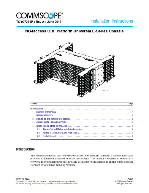
Content Page660001102Rev A Page 1This product is covered by one or more U.S.patents or their foreign equivalents.©2017CommScope. For patents,see /ProductPatent/ProductPatent.aspx All Rights Reserved.Installation InstructionsINTRODUCTION (1)1PRODUCT DESCRIPTION (22)MAIN COMPONENTS (33)GROUNDING AND BONDING THE CHASSIS (44)CHASSIS INSTALLATION PROCEDURE .........................................................45WHERE TO FIND OTHER INFORMATION .. (6)5.1Adapter Pack and Module Installation Instructions...........................................65.2Routing of Cables,Fibers,and Patch Cords................................................65.3Product Support (6)INTRODUCTIONThis installation manual describes the NG4access ODF Platform Universal E-Series Chassis andprovides all information needed to install this product.This product is intended to be used in aNetwork Telecommunication Facilities and is suitable for installation in an Integrated BondingNetwork or a Common Bonding Network.NG4access ODF Platform Universal E-Series ChassisTC-90724-IP ∙ Rev A ∙ June 2017TC-90724-IP •Rev A •June 2017Page 2©2017CommScope .All Rights Reserved.Revision HistoryTrademark InformationCommscope (logo)and CommScope are trademarks.AdmonishmentsAdmonishments —in the form of Dangers,Warnings,and Cautions —must be followed at all times.These warnings are flagged by use of the triangular alert icon,shown below.Danger isused to indicate thepresence of a hazard thatwill cause severe personaldeath,or substantial property damage if the hazard is not avoided.Warning is used to indicate the presence of a hazard that may cause severe personal death,or substantial property damage if the hazard is not avoided.Caution is used to indicate the presence of a hazard that will or may cause minor injury or property damage if the hazard is not avoided.General Warning and Caution StatementsAvoid eye exposure to unmated connectors.Unmated connectors may emit invisible radiation.Do not look directly into the end of a connector or an adapter port.Do not inspect with a magnifying device.To ensure safety,maintain caps on unmated connectors at all times.Handle cables with care.Fiber optic cable stubs should be handled with care the installation procedure to avoid kinking and damage to cables.1PRODUCT DESCRIPTIONThe NG4access universal E-series chassis is a 19-inch (48.26cm)rack-mount,high-density fiber optic panel providing up to 576terminations using LC adapters (or 288SC terminations).A NG4access frame fully loaded with six universal chassis provides 3456LC terminations per frame in a GR-449compliant footprint.The chassis has features providing quick and easy access for connection and routing of fibers.•Universal LC or SC adapter packs may be used with singlemode or multi-mode,APC orUPC connectors.LC packs have 12adapters per pack (24per access tray).SC packs have six adapters per pack (12per access tray).•Access trays may be moved toward front or rear to provide easy access to adapters fromthe front or rear side of the frame.ISSUEDATE REASON FOR CHANGE 1June 2017Original.TC-90724-IP•Rev A•June2017•Access trays may also be loaded with cabled modules that snap into position.Each cabled module is pre-terminated with24LC or12SC adapter/connectors and fibers.Snap-inMPO and VAM modules are also available.•Routing guides manage the fibers within the chassis,allowing an access tray to be opened or closed with no pulling or pinching of fibers.2MAIN COMPONENTSFigure1shows the main components of the universal E-series chassis.They are as follows:Figure1.Main Components of NG4access Universal E-Series Chassis•Access Tray—may be moved toward front or rear to provide front or rear access to adapter packs with the associated fibers and connectors. In place of adapter packs, eachaccess tray may hold a snap-in cabled module, MPO module, or V AM module.•Universal Adapter Pack (LC or SC)—may be used with singlemode or multi-mode, APC or UPC connectors.LC packs have24adapters.SC packs have12adapters,•Routing Guide—holds fibers in an optimal route when access trays are moved toward the front or rear of the chassis.•Mounting Tab—provides a physical interface for mounting the chassis on a frame. The tabs hold four mounting screws, two on each side.Page3©2017CommScope.All Rights Reserved.TC-90724-IP •Rev A •June 2017Page 4©2017CommScope .All Rights Reserved.•Guide Strip —provides cable management for fibers routed into the chassis on the front orrear of the frame.3GROUNDING AND BONDING THE CHASSISThe universal E-series chassis uses thread-forming mounting screws to provide an electrical path between the chassis and the metalwork in which it is mounted.It is required that nonconductive coatings must be removed on the mating metal surfaces.Before installation the mating surfaces must be cleaned and coated with an antioxidant.Always consult and conform to local regulations when grounding and bonding this product.4CHASSIS INSTALLATION PROCEDURE1.Identify the frame location where chassis will be installed.Prepare area around mountingholes to provide a proper ground (remove paint,clean,and coat with rust preventative).2.Install screws and star washers into the two left side holes on the rack to hang the chassison the rack,then install screws and washers in the right two holes.See Figure 2.Figure 2.Installing Chassis in FrameThe frame has six locations for mounting of the chassis.TC-90724-IP•Rev A•June2017 3.Install guide strips(provided)on front and rear of chassis.To install a strip,align the tabson the strip with the slots on the chassis as shown in rear view in Figure3,then press the radius limiters into place as shown.Repeat for all four locations.Figure3.Installing Guide Strip On Universal E-Series ChassisPage5©2017CommScope.All Rights Reserved.TC-90724-IP •Rev A •June 2017Page 6©2017CommScope .All Rights Reserved.5WHERE TO FIND OTHER INFORMATION 5.1Adapter Pack and Module Installation InstructionsFor adapter pack installation instructions,refer to the laminated cards hanging on the front or rear of the frame.For module installation instructions,refer to the laminated cards hanging on the rear of the frame.5.2Routing of Cables,Fibers,and Patch CordsThis product is designed for use with RBR (Reduced Bend Radius)fiber.For cable routing on the rear of the frame,refer to the laminated cards hanging on the rear of the frame.For patch cord routing,refer to the laminated cards hanging on the front of the frame.5.3Product Support/SupportCenter。
螺旋HD二目锦囊用户指南说明书

32Objective LensOcular Lens IPDThe eyecups on a Razor HD binocular twist up and down so any viewer can see the full field and enjoy comfortable viewing—withor without eyeglasses.When not using eyeglasses or sunglasses, keep the eyecups fully extended. For the best viewing when viewing through eyeglasses, twist eyecups down.Adjust the interpupillary distance The interpupillary distance (IPD) is the distance between the centers of the left and right eye pupils. Match the IPD of your eyes to that of the binocular so that you see a single image that is free of shading.B asic O peratiOn Adjust the eyecups Rotate the binocular barrels inward or outward to line your eyes up with ocular lenses.Distance between the centers of the ocular lenses.StrapSocketCenter Focus Diopter54Properly focus the binocularFor the best views, follow this two-stepprocess to properly adjust the center focusand diopter. Choose an object that is about20 yards away from you and stay in the samespot until you have adjusted the binocular for your eyes.1. Adjust the center focus —start by closing your right eye or covering the right objective lenswith your hand. Focus your left eyeon the object and adjust the centerfocus wheel until the image is in focus.Leave the center focus in this positionas you adjust the diopter.2. Adjust the diopter —start by closing your left eye or covering the left objective lens with your hand. Lift the diopter ring tounlock and, looking through yourright eye, adjust the diopter so that theobject is in focus. Make note of thisdiopter setting in case you need to setit again. Push the diopter ring down tolock—from this point on, you will only need to use the center focus wheel.The Razor HD comes with a rainguard for the ocular lenses and tethered objective lens covers. Use these covers to protect the lenses whenever you are not viewing.Lens Covers The protective case of the Razor HD provides safe storage between viewing sessions. The carry strap is already attached to the case.Carry Case a ccessOries Attach the padded neckstrap to the Razor HD in three simple steps. Begin with the right barrel of the binocular and repeat the process for the left barrel.Neckstrap 1. Push a few inches of the strap through the strap attachment on the binocular. 3. Adjust the overall length, then pull tight until strap secured within the buckle.2. Hold the buckle and thread the end of the strap through the buckle.Note: If using another type of strap, never attach metal o-rings directlyonto the strap attachment.Adjust Diopter Setting7 6Caution: Binoculars are not intended for looking at the sun, or any other intense light source. Such viewing could damage the retina and cornea of your eyes—even to the point of causing blindness.L ens c areMaintain the optical brilliance of the Razor HD binocular by keeping lens surfaces free of dirt, oils, and dust.Protect lenses while out in the field Make use of the provided eyepiece and objective lens covers to protect the lenses when not viewing. Then, store the Razor HD in its carry case between viewing sessions.Keep lenses clean In order to enjoy the best views through your Razor HD binocular, take time to regularly clean the exterior lenses:1. Remove any dust or grit from lenses before wiping. Use a can of pressurized air, soft camel hair brush, or an acrylic optical brush.2. Clear lenses of smudges, fingerprints, or eyelash oil. Fog the lenses with your own breath, then use a non-abrasive lens cloth to clean the lenses. Alternately, use a lenscleaning fluid and optical paper to cleanlenses.Never use facial tissue, heavy cotton, orflannel clothing on lenses—these materialscan scratch the surface of a lens.t he Vip W arranty We build optics based on our commitment to your absolute satisfaction. That’s why Vortex products are unconditionally guaranteed and we make this Very Important Promise to you—a Very Important Person. Rest assured that in the event your Razor HD binocular becomes damaged or defective, Vortex Optics will repair or replace the binocular at no charge to you. Call Vortex Optics at 800-426-0048 for prompt, professional, and friendly service.Vortex Optics 2120 West Greenview Drive Middleton, WI 53562************************Visit for more information. Canadian customers may visit for customer service information. The VIP Warranty does not cover loss, theft, deliberate damage, or cosmetic damage that does not hinder the performance of theproduct.。
Bosch DS306E PIR 侦测器说明书

u Procesamiento Motion Analyzer IIu Espejos orientables reemplazables en el campou Tres patrones de coberturau Cuatro opciones de montajeEl detector PIR de montaje en pared DS306E disponede espejos orientables reemplazables en el campo yemplea el procesamiento de señales Motion Analyzer IIpara disminuir el número de falsas alarmas. La óptica,los patrones de cobertura y opciones de montajeaportan flexibilidad de instalación.Funciones básicasProcesamiento de señalesMotion Analyzer II utiliza múltiples umbrales yventanas de tiempo para analizar la frecuencia,amplitud, duración y polaridad de las señales paratomar la decisión de activar una alarma.Certificados y homologacionesFrancia AFNOR NF, A2PPlanificaciónConsideraciones para el montajeEl detector PIR DS306E tolera cambios detemperatura derivados de calefactores, aparatos deaire acondicionado y corrientes. También tolerafluctuaciones de la iluminación derivadas de la luzsolar, de rayos y luces de vehículos en movimiento.7.5 m Vista superiorCobertura de ancho estándar: 15 m x 15 m (50 pies x 50 pies)Vista lateralCobertura de ancho estándar: 15 m x 15 m (50 pies x 50 pies)0 m 0 m10 f 10 f 80 f t25 m3 m 3 mVista superiorCobertura de barrera opcional: (OMB77) 25 m x 5 m (80 pies x 16 pies)0 m3 m 25 m Vista lateralCobertura de barrera opcional: (OMB77) 25 m x 5 m (80 pies x 16 pies)0 m0 m 36 m 1.5 m 1.5 m Vista superiorCobertura de largo alcance opcional: (OMLR77) 40 m x 3 m (120 pies x 10 pies)120 ft36 m Vista lateralCobertura de largo alcance opcional: (OMLR77) 40 m x 3 m (120 pies x 10 pies)Especificaciones técnicas Diseño de la caja de protecciónConsideraciones medioambientalesMontajeSalidasRequisitos de alimentaciónInformación sobre pedidosDetector PIR de montaje en pared DS306EDetector PIR de montaje en pared DS306ENúmero de pedido DS306EDetector PIR de montaje en pared DS306E para FranciaDetector PIR de montaje en pared DS306E para FranciaNúmero de pedido DS306E-FRAAccesorios de hardwareSoporte con rótula de montaje en pared B328Se monta en una caja eléctrica unitaria y permite el giro del detector. Los cables se encuentran en el interior.Número de pedido B328Soporte de montaje giratorio de bajo perfil B335-3 Soporte de plástico giratorio de bajo perfil para montaje en pared. El rango de giro vertical es de +10°a -20°; el rango de giro horizontal es de ±25°. Disponible en paquetes triples.Número de pedido B335-3Espejo de barrera OMB77‑3Proporciona una cobertura de barrera con una proyección de 25 m x 5 m (80 pies x 16 pies). Viene en paquetes de tres.Número de pedido OMB77-3Espejo de largo alcance OMLR77‑3Proporciona una cobertura de largo alcance con una proyección de 40 m x 3 m (120 pies x 10 pies). Viene en paquetes de tres.Número de pedido OMLR77-3Cable de prueba TC6000Cable de prueba para conectar las patillas de prueba de un detector compatible a un voltímetro. Tiene una longitud de 4,6 m (15 pies).Número de pedido TC6000Representada por:Spain:Americas:America Latina:Bosch Security Systems, SAUC/Hermanos García Noblejas, 19 28037 MadridTel.: +34 914 102 011Fax: +34 914 102 056**************************** www.boschsecurity.es Bosch Security Systems, Inc.130 Perinton ParkwayFairport, New York, 14450, USAPhone: +1 800 289 0096Fax: +1 585 223 9180***********************.comRobert Bosch LtdaSecurity Systems DivisionVia Anhanguera, Km 98CEP 13065-900Campinas, Sao Paulo, BrazilPhone: +55 19 2103 2860Fax: +55 19 2103 2862*****************************© Bosch Security Systems, SAU 2013 | Información sujeta a cambios sin previo aviso 2603646347 | es, V1, 01. Oct 2013。
iOptron 80mm 反射望远镜(R80)说明书
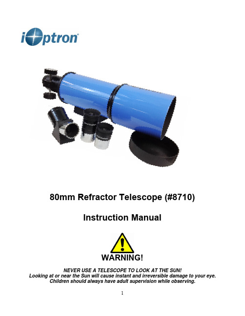
80mm Refractor Telescope (#8710)Instruction ManualWARNING!NEVER USE A TELESCOPE TO LOOK AT THE SUN!Looking at or near the Sun will cause instant and irreversible damage to your eye.Children should always have adult supervision while observing.1. DescriptionThe iOptron ® 80mm refractor (R80) is a fantastic astronomy telescope that is portableenough to take anywhere. With fully multi-coated optics, the R80 reveals brighter and sharper images. The 80mm objective lens and short 400mm (f/5.0) focal length are perfect for taking in wide swaths of the heavens, making it ideal for larger deep-sky objects. You'll see spectacular star clusters, wispy nebulas, and expansive galaxies with this telescope, but it also excels at viewing objects in our solar system. Enjoy experiencing the phases of the Moon and tracking the motions of the planets with crisp views of Saturn's rings and Jupiter's moons, as well as the birds and other land objects.iOptron R80 is a great candidate for a guidescope. It can be easily attached to a largerprimary telescope tube assembly with the proper mounting rings and dovetail. The scope will accept digital SLR, small CCD camera, or a stand-alone autoguider with a proper adapter.Figure 1. 80mm refractor2. Telescope SetupThe R80 telescope comes with a Vixen-type dovetail. It can be mounted onto anytelescope mount that accepts a Vixen-type dovetail. Just simply release the dovetail locking knob on the dovetail saddle. Slide the telescope dovetail bar in and lock the dovetail locking knob.Figure 2. Install the R80 telescope onto a telescope mountIf you only have a camera tripod, you can mount the telescope onto it via a ball head,which will provide needed telescope movement. There is a ¼” threaded hole on R80 dovetailDovetail lock knobLens CoverDew Shield Telesope Main Tube DovetailBarFocuserDiagonalEye Piecebar. Install the quick release plate of the ball head onto the dovetail bar and insert the quickrelease plate to the ball head and secure it.Figure 3. Mount a R80 telescope onto a camera tripodInsert the diagonal into the eyepiece side of the telescope. Tighten the thumbscrews to afirm feel only. Slide the eyepiece into the open end of the diagonal . Tighten the. Remove the dust cover from the other end of telescope before observation.Figure 4Figure 53. Telescope Operation3.1. Imaging OrientationThe image orientation changes depending on how the eyepiece is inserted into thetelescope. When using the star diagonal (the included 90º mirror diagonal), the image is right-side-up, but reversed from left-to-right (i.e., mirror image). If inserting the eyepiece directly into the visual back (i.e., without the star diagonal), the image is upside-down and reversed from left-to-right (i.e., inverted). This is normal for the refractor design.Actual image orientation as seen with the unaided eye Reversed from left to right, as viewed with a Star DiagonalInverted image, as viewed with the eyepiece directly intelescope Corrected image, as viewed with a Erect Lens or Erect DiagonaleyepieceFocus knob45° diagonalFor terrestrial observation, such as land mark or bird viewing, you can buy an optional 45º Erect Diagonal to have a correct image from your eyepiece.3.2. Selecting an EyepieceThe magnification of a telescope is defined by the focal lengths of the telescope and the eyepiece. A formula can be used to determine the power of each eyepiece: Telescope focal length divided by eyepiece focal length equals magnification.For example, a R80 telescope has a focal length of 400mm. With a 25mm eyepiece, the magnification will be400mm ÷ 25mm = 16X (magnification)If you want more magnification, you may order higher power eyepieces. Note: a 25 mm focal length eyepiece has a lower power than a 10 mm one. Always start with the lowest power eyepiece for easy locating the objects.3.3. Focusing TelescopePractice telescope focusing during the daytime to get familiar with the scope.(1) After selecting the desired eyepiece aim the telescope tube at a land-based target at least 200 yards away (e.g. A telephone pole or building). Fully retract focusing tube by turning the focus knob.(2) While looking through selected eyepiece, slowly extend focusing tube by turning focusing knob until object comes into focus.4. Specifications:Product Name iOptron 80mm OTA (#8710)Optical Design Air-Spaced Doublet Achromatic RefractorOptical Coatings Fully Multi-CoatedClear Aperture 3.15" (80mm)Focal Length 15.7" (400mm)Focal Ratio f/5Resolving Power 1.4 arcsecLimiting Visual Magnitude 11.3Highest Useful Magnification 189Focuser 1.25" rack-and-pinionEyepiece adapter 1.25 inchEyepiece 1 25 mmEyepiece 2 10mmDiagonal 40º erect glass prismWeight (OTA) 2.2 lbsWarranty One year limited。
《Bosch Video Management System Operator Client V4

6.1
显示地图
6.2
控制 PTZ 摄像机
6.3
使用摄像机的窗内控制
Bosch Sicherheitssysteme GmbH
操作手册
目录 | zh 3
6 6 6
8
9 9 9 9
10 10 10 10
12 12 12 12 13 13 13 14 14 15 15 15 15 16 16 16 16 17 17 17 17 18 18
4
使用入门
本章介绍有关如何启动 Bosch Video Management System 和 Bosch VMS Archive Player. 的信息。
4.1
安装软件模块
注意 不要将 DiBos Web 客户端安装在任何 Bosch VMS 计算机上。否则,在 Web 客户端启动后,每个 Web 客户端计算机上的 Operator Client 将会崩溃。
4.3
启动 Operator Client
5
显示摄像机图像
5.1
在图像窗格中显示摄像机
5.2
在逻辑树中查找项目
5.3
排列图像窗格
5.4
显示报警图像窗口
5.5
启动手动录像
5.6
启动预配置的摄像机序列
5.7
启动自动摄像机序列
模式
5.10
使用数字变焦
5.11
保存单个图像
12 12.1 12.2 12.3
13 13.1
14 14.1 14.2 14.3
参考图像 对话框 选择搜索参数 对话框 ATM/POS 选项 对话框 选择虚拟输入过滤器设置 对话框 设备选择 对话框 事件选择 对话框 日志结果 对话框 选件 对话框 逻辑树 窗口 搜索 对话框 收藏夹树 窗口 导出树 窗口 地图 窗口 云台控制 窗口 监视器 窗口 图像窗口 图像窗格 时间链 窗口 移动搜索 对话框 导出视频 对话框 删除视频 对话框 防伪搜索 对话框 (仅限 VRM 录像) 保护视频 对话框 取消保护视频 对话框 移动搜索结果 窗口 视频搜索结果 窗口 报警列表 窗口 事件列表窗口 所用的图标
博斯科普单目、双目和三目显微镜产品说明书
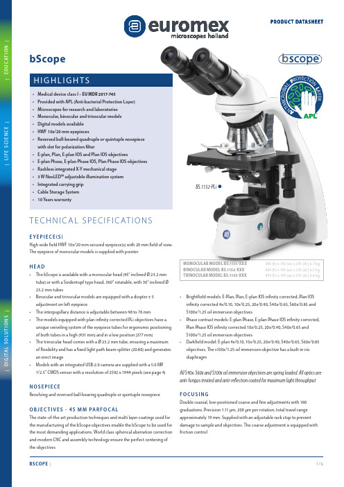
MONOCULAR MODEL BS.1151-XXX385 (h) x 195 (w) x 235 (d) | 6.3 kg BINOCULAR MODEL BS.1152-XXX 409 (h) x 195 (w) x 235 (d) | 6.5 kg TRINOCULAR MODEL BS.1153-XXX 459 (h) x 195 (w) x 235 (d) | 6.6 kgBS.1152-PLi™A NT I MI C R O B I A L PR O T E C T I O NL A Y E R NSHigh wide field HWF 10x/20 mm secured eyepiece(s) with 20 mm field of view. The bScope is available with a monocular head (45° inclined Ø 23.2 mmC arrying gripAll models are equipped with a 152/197 x 131 mm stage with integrated 75 x 36 mm X-Y rackless mechanical stageSome models are also available as medical device, EU MDR 2017-745, contact your Euromex dealerBS.1151-EPL BS.1152-PLiBS.1153-PLPHiBS.1157-EPLi409 (h) x 195 (w) x 235 (d) | 7.1 kgBS.1157-PLi™A NTIMICROBIALP R O T E C T I ONLAYERO NSThe digital bScope microscopes are equipped with a 5.0 MP 1/2.5 inch CMOS USB-2.0 camera, 24 bits color depth, 7 frames per second (2592 x 1944 pixels) or 27 frames per second (1280 x 960 pixels). Dynamic range is 76 db and signal/noise ratio 41 db. Supplied with USB-2.0 cable and a micrometerThe capture and analysis ImageFocus Alpha software allows to save images in .jpg, .tif, .bmp or .dicom formats as well as .avi format videos. Measurements and annotations can be done on live or captured images. Compatible with Windows 10 and 11, both 32 and 64 bits configurations. A Mac OS version is also available. Free updates can be downloaded from our website| D I G I T A L S O L U T I O N S || E D U C A T I O N || L I F E S C I E N C E |PROD UC T DATAS HEE TP H A S E CO N T R A S T ACC E S S O R I E SBS.9118 Z ernike phase contrast kit with E-plan EPLPH 10/20/S40 andS100 oil phase contrast objectives, Zernike rotating condenser, telescope and green filterBS.9120 Z ernike phase contrast kit with E-plan EPLPHi 10/20/S40 andS100 oil phase contrast IOS infinity corrected objectives, Zernike rotating condenser, telescope and green filterBS.9123 Z ernike phase contrast kit with plan PLPH 10/20/S40 and S100 oilphase contrast objectives, Zernike rotating condenser, telescope and green filterBS.9126 Z ernike phase contrast kit with plan PLPHi 10/20/S40 and S100oil phase contrast IOS infinity corrected objectives, Zernike rotating condenser, telescope and green filterBS.9164 P hase contrast kit with Abbe condenser with slot for slider. PlanPLPHi phase S40x contrast objectives, slider with 40x annuli only, telescope and green filterBS.9194 S lider with phase contrast annuli 40x. Needs BS.9102 condenserwith slotBS.9148 Alignment telescope for bScope IOS version with 30 mm tubes BS.9149 A lignment telescope for bScope non IOS version with 23.2 mmtubesBS.9156 P hase contrast kit with Abbe condenser with slot for slider.E-plan EPLPH 10/S40x phase contrast objectives, slider with 10 and 40x annuli, telescope and green filterBS.9157 P hase contrast kit with Abbe condenser with slot for slider.E-plan EPLPH 20/S100x phase contrast objectives, slider with 20 and 100x annuli, telescope and green filterBS.9158 P hase contrast kit with Abbe condenser with slot for slider.E-plan EPLPH i 10/S40x phase contrast infinity corrected objectives, slider with 10 and 40x annuli, telescope and green filterBS.9159 P hase contrast kit with Abbe condenser with slot for slider.E-plan EPLPHi 20/S100x phase contrast infinity corrected objectives, slider with 20 and 100x annuli, telescope and green filterBS.9162 P hase contrast kit with Abbe condenser with slot for slider. PlanPLPHi 10/S40x phase contrast infinity corrected objectives, slider with 10 and 40x annuli, telescope and green filterBS.9163 P hase contrast kit with Abbe condenser with slot for slider.Plan PLPHi 20/S100x phase contrast infinity corrected objectives, slider with 20 and 100x annuli, telescope and green filterP O L A R I Z AT I O N AT TAC H M E N T SBS.9647 P olarization polarizer 16 mm diameter for slider under bScopeheadBS.9651 P olarization attachment for lamphouse of bScope with 360°scaleBS.9660 P olarization kit: analyzer under head and polarizer onlamphouseAE.5152-N Small rotatable stage to be used with BS.9660BS.7240 Plan PL S40x/0.65 objective. WD 0.56 mm BS.7260 Plan PL S60x/0.85 objective. WD 0.25 mmBS.7200 Plan PL S100x/1.25 oil immersion objective. WD 0.33 mm BS.7510 E -Plan Phase EPLPH 10x/0.25 objective. WD 6.61 mm BS.7520 E-Plan Phase EPLPH 20x/0.40 objective. WD 1.85 mm BS.7540 E -Plan Phase EPLPH S40x/0.65 objective. WD 0.64 mm BS.7500 E -Plan Phase EPLPH S100x/1.25 oil immersion objective.WD 0.19 mmBS.8204 E -plan EPLi 4x/0.10 infinity corrected IOS objective. WD 18.9 mm BS.8210 E -plan EPLi 10x/0.25 infinity corrected IOS objective.WD 5.95 mmBS.8220 E -plan EPLi 20x/0.40 infinity corrected IOS objective.WD 2.61 mmBS.8240 E -plan EPLi S40x/0.65 infinity corrected IOS objective.WD 0.78 mmBS.8200 E -plan EPLi S100x/1.25 oil immersion infinity corrected IOSobjective. WD 0.36 mmBS.8404 P lan PLi 4x/0.10 infinity corrected IOS objective. WD 21.0 mm BS.8410 P lan PLi 10x/0.25 infinity corrected IOS objective. WD 5.0 mm BS.8420 P lan PLi 20x/0.40 infinity corrected IOS objective. WD 8.8 mm BS.8440 P lan PLi S40x/0.65 infinity corrected IOS objective. WD 0.66 mm BS.8460 P lan PLi S60x/0.85 infinity corrected IOS objective. WD 0.46 mm BS.8400 P lan PLi S100x/1.25 oil immersion infinity corrected IOSobjective. WD 0.36 mmBS.8510 E -Plan Phase EPLPHi 10x/0.25 infinity corrected IOS objective.WD 5.95 mmBS.8520 E -Plan Phase EPLPHi 20x/0.40 infinity corrected IOS objective.WD 2.61 mmBS.8540 E -Plan Phase EPLPHi S40x/0.65 infinity corrected IOS objective.WD 0.78 mmBS.8500 E -Plan Phase EPLPHi S100x/1.25 oil immersion infinity correctedIOS objective. WD 0.36 mmBS.8710 P lan Phase PLPHi 10x/0.25 infinity corrected IOS objective.WD 5.00 mmBS.8720 P lan Phase PLPHi 20x/0.40 infinity corrected IOS objective.WD 8.80 mmBS.8740 P lan Phase PLPHi S40x/0.65 infinity corrected IOS objective.WD 0.66 mmBS.8700 P lan Phase PLPHi S100x/1.25 oil immersion infinity corrected IOSobjective. WD 0.36 mmCO N D E N S E R S A N D ACC E S S O R I E SBS.9102 A bbe condenser 1,25 NA with slot for darkfield and phase contrastsliders. Without darkfield slider and without phase contrast sliderBS.9170 D arkfield stop for BS.9102 condenser BS.9105 Swing-out Abbe condenser 0.9/1.25 NAEuromexMicroscopenbv•Papenkamp20•6836BDArnhem•TheNetherlands•T+31(0)263232211•****************•AE.9919AE.9916BS.1153-PLiwith camera。
Olympus 显微镜和 Olympus CellSens 的使用指南说明书
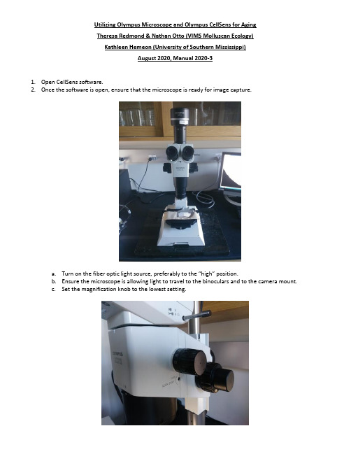
Utilizing Olympus Microscope and Olympus CellSens for AgingTheresa Redmond & Nathan Otto (VIMS Molluscan Ecology)Kathleen Hemeon (University of Southern Mississippi)August 2020, Manual 2020-31.Open CellSens software.2.Once the software is open, ensure that the microscope is ready for image capture.a.Turn on the fiber optic light source, preferably to the “high” position.b.Ensure the microscope is allowing light to travel to the binoculars and to the camera mount.c.Set the magnification knob to the lowest setting.3.Select a specimen and, using the finger bowl filled with glass beads, orient the specimen with the curved edge ofthe valve pointing down so that it is secured by the beads. Orient the polished surface of the valve so that it is as perpendicular to the microscope lens as possible, with the hinge region located as close to the center of the finger bowl as possible to provide for the most range of movement on the stage.4.Ensure that each hinge is clean, free of debris, and finger smudges.5.Each hinge must be leveled, back to front and side to side, for the entire plane of the hinge. This ensures thehinge will be properly in focus. There is a level located next to the microscope for completion of the step.6.Once the specimen is aligned, use the fiber optic light source to illuminate the hinge region as evenly andbrightly as possible from a steep angle so that reflections and glare are minimized.7.Back in CellSens, click on the leftmost tab (labeled “Camera Control”) at the bottom of the column on the rightside of the screen.8.Toggle “RGB/Grayscale Mode” to “Grayscale” (if not already set).a.This setting appears as a small button below “Live” and looks like a few small blocks of grey to whiterectangles when set to greyscale. It will appear as red, green, and blue rectangles with grey if RGB isenabled.9.Under the “DP73: Custom Grey Scale” there are three buttons for contrast options; “low”, “medium”, and“high.’” Select “high.”10.At the top of the column “Camera Control,” click the button with a picture of a hand atop a video camera. If youhover the pointer over this button, it will display “Acquisition Settings.”11.In the left column of the dialog box that appears is a setting tree la beled “Document Name.” Click here, thenclick on “Snapshot” or “Process Manager” to access settings to customize the automatic naming format for files.This is where you can set automatic naming for still images and for “Manual Image Alignment” processes.Modify as necessary for the samples being processed.12.Close the “Acquisition Settings” dialog box once appropriate settings have been made.13.Click the “Live” button at the top of the column on the right side of the screen called “Camera Control.”14.A live image of the field of view of the microscope should appear on screen. Adjust the stage and the specimenuntil the polished section of the hinge appears within the field of view.15.Adjust the lighting as necessary to ensure even illumination of the specimen.a. A method that seems to prove effective is to set up the lighting such that the growth lines cup theincoming light direction. The lights are approximately in a 45 degree downward angle about 2-3 inchesfrom the hinge.16.Adjust “Exposure” under the “Camera Control” tab. The exposure appears as a square dotted line box on thenear the live image. This box can be moved around to sample lighting for auto-exposure. The exposure box size can be adjusted b ut is typically set at “spot 1%.” Exposure can also be locked and adjusted incrementally by using the manual setting.17.Once zoomed in and image focus has been optimized take images as necessary using the “Snapshot” icon. Ifmultiple images are needed to be stitched together, see a (below). If only one image is necessary, proceed to step 18. It is important to remember to always update the magnification on the computer when magnification on scope changes. A fully stitched hinge photo is typically taken at minimum of 32 power. A single non stitched photo of the growth edge must also be included at a minimum of 90 power.a.Zoom in on the growing edge of the hinge region so that the most recent growth lines are visible. Ensurethat the magnification menu at the top of the screen is set to the magnification of the microscope beingused to capture images (0.7x = 7, 1x = 1, etc.)b.Click on the tab at the bottom of the column on the right side of the screen labeled “Process Manager.”c.Ensure t hat the “Manual Processes” radio button is selected and that the button for “Manual MIA” isselected.d.Click the “Start” button at the top of the column to begin capturing images for a series of stitchedimages.e.Click the arrow buttons in the direction that you wish to capture and stitch additional images. You willneed to move the stage so that the image on the screen moves in only the direction you want to takethe next image. When ready to capture and stitch the image, click the arrow for the next image. Thenreview the quality of the previous stitch, and if it is not good then click the “undo last frame” button toretry.●*Sometimes Helpful Tip* Try to move the image just past the position of best alignment sothat the software can detect alignment. If the image is not moved far enough, or if thealignment is too perfect, then stitching will perform poorly.f.Repeat step e until the entire hinge section from growing edge to origin is captured. A helpful trick toavoid a poor stitch of the final image is to click on a directional arrow after the last image of the origin sothat the stitch can be examined before completion.g.Position the scale bar as close to the origin/growth edge as possible without covering the essentialgrowth lines. To move the scale bar, click on the “Tools” menu, then “Options (Shift +F8)”. Select “ScaleBar”, “Display”, “Select Position”. There are f our corner options to position the scale bar.i.If the scale bar is greyed out and not seen, move the “Info Stamp” and/or “Color Bar” options tofree the corner spot. Even though the “info stamp” or “color bar” are not in use, their selectedplacement options will still block selecting a scale bar position.h.Click the stop button to finish the process and finalize the stitching of the image.18.After the image is complete, you can adjust the image balance (if needed). Not all images need this howevermost do improve with it. Use the below options sparingly and consider levelness of the hinge, focus, light intensity, angle of light first before using this as a solution.a.Select “Adjust Display” (next to the Process Manager tab) and use “Display Enhancement” sliders;“Brightness”, “Contrast”, and “Gamma.”b.Work in small increments to get the proper balance. Start with a small increase in contrast then lowerthe gamma. The brightness setting is adjustable but typically only when the contrast and gamma do nothelp. Look for the best settings that help define all the important lines throughout the growth series. Beaware that these image adjustments also exaggerate over and under exposed areas of the image thatcan hide important growth lines.19.Select the image tab of the image you want to save near the top of t he screen to the right of the “Start Page”tab.20.Click “File,” “Save as,” and then select the appropriate location for the file to be saved.21.When naming files, it is helpful to append the file name with the sample ID of the specimen and include an “L”or “R” depending on if it is the left or right hand valve. Be sure to include any other pertinent information about the shell being imaged.22.Save a version of the file as a .VSI, the proprietary format of the Olympus software, first (if stitching imagesonly). Then save a version with the same name as a .JPG for ease of post-processing.23.When finished, ensure all images generated are saved and shut down the computer. Turn off the fiber optic lightsource and cover the microscope.。
Bosch Security Systems 软件手册 AM18-Q0635说明书
Bosch Security Systems
软件手册
目录 | zh 5
37 37 37 37 37 37 38 39 39 39 39 39 39 39 39 39 40 40 40 41 41 41
42 42 42 42 42 42 42 42 42 42 43 44 45 45
AM18-Q0635 | v5.6 | 2013.01
摄像机浏览器界面
NIN-832 FW5.7
zh 软件手册
摄像机浏览器界面
目录
1 1.1 1.2 1.2.1 1.3
浏览器连接 系统要求 建立连接 摄像机中的密码保护 受保护的网络
2
系统概述
2.1
实况页面
2.2
录像
2.3
设置
3 3.1 3.1.1 3.1.2 3.1.3 3.1.4 3.1.5 3.1.6 3.1.7 3.1.8 3.1.9 3.1.10 3.1.11 3.2 3.2.1 3.2.2 3.2.3 3.2.4
设置
Bosch Security Systems
软件手册
目录 | zh 3
12 12 13 13 13
14 14 14 14
15 15 15 16 17 18 19 20 20 20 20 20 21 22 22 23 23 24
26 26 27
AM18-Q0635 | v5.6 | 2013.01
网络 网络访问 自动 IP 分配 IP V4 地址 IP V6 地址 DNS 服务器地址 视频传输 TCP 速率控制 HTTP 浏览器端口 HTTPS 浏览器端口 RCP+ 端口 1756 Telnet 支持 接口模式 ETH 网络 MSS [ 字节 ] iSCSI MSS [ 字节 ] 网络 MTU [ 字节 ] 启用 DynDNS 提供商 主机名称 用户名 密码 立即强制注册 通知邮件 状态 高级 SNMP
思博伦octoscope使用手册

思博伦octoscope使用手册摘要:一、引言1.介绍思博伦octoscope的重要性2.阐述本文目的和结构二、产品概述1.产品简介2.主要功能和特点三、安装与配置1.系统要求2.安装步骤3.配置指南四、操作指南1.基本操作2.高级功能3.常见问题解决五、维护与升级1.软件维护2.硬件升级3.故障排查六、安全与合规1.安全措施2.法规遵从七、技术支持与资源1.技术文档2.培训与教程3.联系方式八、结论1.总结octoscope的优势2.建议与展望正文:一、引言在当今高速发展的科技时代,网络性能测试工具的重要性日益凸显。
思博伦octoscope作为一种领先的网络性能测试设备,得到了广泛的关注。
本文旨在为您提供关于octoscope的详细使用手册,帮助您更好地了解并运用这款产品。
本文结构如下:1.介绍思博伦octoscope的重要性2.阐述本文目的和结构二、产品概述1.产品简介思博伦octoscope是一款高性能、高灵活性的网络性能测试设备,具备丰富的功能和强大的数据处理能力。
它可以帮助您全面了解网络性能,找出潜在问题,并为优化网络提供有力支持。
2.主要功能和特点- 支持多种数据平面协议:如TCP、UDP、HTTP、HTTPS等;- 支持灵活的测试场景配置;- 支持大规模数据包发送和接收;- 支持实时数据包分析与统计;- 提供丰富的报告和可视化界面;- 支持远程控制与监控;- 易于安装、配置和管理。
三、安装与配置1.系统要求在开始安装octoscope之前,请确保您的服务器或测试设备满足以下系统要求:- 操作系统:Windows、Linux或macOS;- 处理器:至少双核心;- 内存:至少4GB;- 硬盘空间:至少100GB。
2.安装步骤请按照以下步骤进行octoscope的安装:- 下载安装包;- 解压安装包;- 运行安装程序;- 按照提示完成安装。
3.配置指南在安装完成后,您需要对octoscope进行配置。
iScope 极光显微镜系列产品说明书
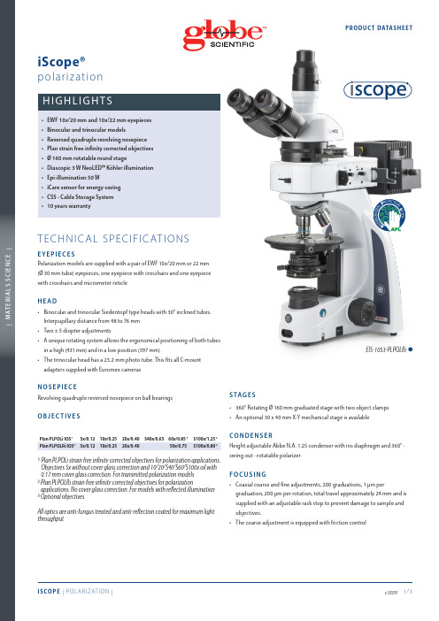
EIS-1053-PLPOLRi ™A N T I MI C R O B I AL PR O T E C T I O NL A Y E R Polarization models are supplied with a pair of EWF 10x/20 mm or 22 mm (Ø 30 mm tube) eyepieces, one eyepiece with crosshairs and one eyepiece inocular and trinocular Siedentopf type heads with 30° inclined tubes. unique rotating system allows the ergonomical positioning of both tubesntensity adjustable 3 W Köhler NeoLED™ illumination with internal 100-he larger aperture of NeoLED™ allows the optical systems of the iScope®microscope to produce images at higher resolutions, very close to thehe Köhler diaphragm provides homogeneous illumination andolarisation models with transmitted light only are supplied with: 360°rotatable polarization filter, 360° rotatable analyzer with 180 incrementsand nonius for 0.2 degree readout, Bertrand lens (build-in), 1 λ first red and1/4 λ retardation plate, a quartz wedge, 45 mm green and blue filters forquipped with a 50 W 12 V halogen epi-illumination and externalupplied with 360° rotatable polarization filter, 360° rotatable analyzerwith 180 increments and nonius for 0.2 degree readout, Bertrand lens(build-in), 1 λ first red plate, 1/4 λ retardation plate, a quartz wedge, sliderswith green/blue and white/neutral densitiy filter. 45 mm green and blueThe unique iCare Sensor is developed to avoid unnecessary loss of energyhe illumination of the microscope automatically switches off shortly afteriScope® allows users to easily insert the power cable into the back of theEIS-1053-PLPOLi™Euromex Microscopen bv • Papenkamp 20 • 6836 BD Arnhem • The Netherlands • T +31 (0) 26 323 22 11 • info@ • | M A T E R I A L S S C I E N C E |PROD UC T DATAS HEE TACCESSORIES AND SPARE PARTSEIS-6210 EWF 10x/22 mm eyepieceEIS-6210-C EWF10x/22 mm eyepiece with crosshairsEIS-6210-PEWF10x/22 mm eyepiece with pointer EIS-6210-CM E WF 10x/22 mm eyepiece with 10/100 micrometer andcrosshairsEIS-6310E WF 10x/20 mm eyepiece 30 mm tubeEIS-6310-C E WF10x/20 mm eyepiece with crosshairs, 30 mm tube EIS-6310-CM E WF 10x/20 mm eyepiece with 10/100 micrometer andcrosshairs, 30 mm tubeEIS-6215 WF15x/16 mm eyepiece EIS-6220 WF20x/12 mm eyepieceEIS-6299Pair of eyecups for iScope infinity modelsF O R I S CO P E T R A N S M I T T E D P O L A R I Z AT I O NEIS-7905-T P lan strain-free PLPOLi 5x/0.12 IOS objective,no cover glass correction. Working distance 15.5 mmEI S -7910-T P lan strain-free PLPOLi 10x/0.25 IOS objective,0.17 mm cover glass corrected. Working distance 10 mmEI S -7920-T P lan strain-free PLPOLi 20x/0.40 IOS objective,0.17 mm cover glass corrected. Working distance 5.1 mmEI S -7940-T P lan strain-free PLPOLi 40x/0.65 IOS objective,0.17 mm cover glass corrected. Working distance 0.54 mmEI S -7960-T P lan strain-free PLPOLi 60x/0.85 IOS objective,0.17 mm cover glass corrected. Working distance 0.14 mmEI S -7900-T P lan strain-free PLPOLi 100/1.25 oil IOS objective,0.17 mm cover glass corrected. Working distance 0.13 mmEIS-9604 Quartz wedge in slider EIS-9608 Analyzer 0-360° rotatableEIS-9610 Lamda plate first red 530 nm in slider EIS-9612Lamda/4 retardation plate in sliderF O R I S CO P E R E F L E C T E D P O L A R I Z AT I O NEIS-7905-R P lan strain-free PLPOLRi 5x/0.12 IOS objective, no cover glass correction. Working distance 15.5 mm EIS-7910-R P lan strain-free PLPOLRi 10x/0.25 IOS objective, no cover glass correction. Working distance 10 mm EIS-7920-R P lan strain-free PLPOLRi 20x/0.40 IOS objective, no cover glass correction. Working distance 5.8 mm EIS-7950-RP lan strain-free PLPOLRi 50x/0.75 IOS objective, no cover glass correction. Working distance 0.52 mm.EIS-7900-R P lan strain-free PLPOLi S100x/0.80 infinity corrected IOSobjective. No cover glass correction. Working distance 2.0 mm.EIS-9602-RPolarizerEIS-9604-R Quartz wedge in slider EIS-9608-R 360° rotatable analyzer in slider EIS-9610-R Lamda plate first red 530 nm EIS-9612-R Lamda/4 retardation plate in sliderF O R A L L I S CO P E P O L A R I Z AT I O N M O D E L SEIS-7202P lan PLi 2x IOS objective for iScope, working distance 18,3 mm. Best to be used together with swing-out condenserEIS-9600 Polarization filter, 45 mm for lamp house EIS-9700 Blue opaque filter, 45 mm for lamp house EIS-9702 Green opaque filter, 45 mm for lamp house EIS-9704 Yellow opaque filter, 45 mm for lamp house EIS-9706 White opaque filter, 45 mm for lamp house ESL-5500 NeoLED™ replacement unitESL-3679 50 W 12 V spare bulb for unit (Ri type)EAE-3684 T500 mA 250 V Fuses for iScopeEAE-3685 T2 A 250 V Fuses for reflected illumination units power supply EAE-5130 U niversal Ø 23.2 mm tube adapter with built-in 2x lens for SLR photo camera with APS-C sensor. Needs T2 adapter EAE-5025 T2 ring for Nikon D SLR digital camera EAE-5040 T2 ring for Canon EOS SLR digital cameraEPB-5155 Microscope slides 76 x 26 mm, ground edges, 50 pieces EPB-5165 Cover glasses 18 x 18 mm, thickness 0.13-0.17 mm, 100 pieces EPB-5168 Cover glasses 22 x 22 mm, thickness 0.13-0.17 mm, 100 pieces EPB-5245 Lens cleaning paper, 100 sheets per pack EPB-5255 Immersion oil (25 ml). n = 1.515EPB-5274 Isopropyl alcohol 99% (200 ml)EPB-5275 C leaning kit: lens cleaning fluid, lint free lens tissue/paper, brush, air blower, cotton swabs。
CommScope 双重四路双向转换器说明书

Page of 14Twin Quadplexer, 555-894/PCS/AWS/WCS, DC Manual SelectBTS-to-feeder and feeder-to-antenna application Convertible mounting bracketsOBSOLETEThis product was discontinued on: March 18, 2019Replaced By:CQX6192123T-DS-43E12F23P05Twin Quadplexer, 617-894/PCS/AWS/WCS, DC Sense, 4.3-10Product ClassificationProduct TypeQuadplexerGeneral SpecificationsProduct Family CBC6192123ColorGray Common Port Label COMMON Data Port Interface USB Modularity 2-Twin MountingPole | Wall Mounting Pipe Hardware Band clamps (2)RF Connector Interface7-16 DIN Female RF Connector Interface Body StyleLong neckDimensionsHeight 255 mm | 10.039 in Width 175 mm | 6.89 in Depth125 mm | 4.921 in Ground Screw Diameter6 mm | 0.236 in 40–160 mmPage of 24Mounting Pipe Diameter Range40–160 mmOutline DrawingElectrical SpecificationsImpedance50 ohmLicense Band, Band PassAPT 700 | AWS 1700 | CEL 850 | LMR 750 | PCS 1900 | USA 600 | USA 700 | USA 750 | WCS 2300Electrical Specifications, dc Power/Alarmdc/AISG Pass-through Method User selectabledc/AISG Pass-through Path Manual adjustment sets dc/AISG path Lightning Surge Current5 kALightning Surge Current Waveform8/20 waveform15 mA @ 12 V | 15 mA @ 24 VOperating Current at Voltage15 mA @ 12 V | 15 mA @ 24 VVoltage7–30 VdcElectrical Specifications, AISGAISG Carrier2176 KHz ± 100 ppmInsertion Loss, maximum 1 dBReturn Loss, minimum15 dBElectrical SpecificationsSub-module 1 | 2 1 | 2 1 | 2 1 | 2Branch1234Port Designation555-894MHz AWS1850–1990WCSLicense Band APT 700, Band PassAWS 1700, Band Pass PCS 1900, Band Pass WCS 2300, Band PassCEL 850, Band PassLMR 750, Band PassUSA 700, Band PassUSA 750, Band PassUSA 600, Band PassElectrical Specifications, Band PassFrequency Range, MHz555–8941710–17801850–19902305–23602110–2180Insertion Loss, typical, dB0.40.30.30.2Total Group Delay, maximum, ns40255525Return Loss, minimum, dB20202020Return Loss, typical, dB22222222Isolation, minimum, dB50505050Isolation, typical, dB65555555Input Power, RMS, maximum, W200200200200Input Power, PEP, maximum, W20002000200020003rd Order PIM, typical, dBc-153-153-153-1532 x 20 W CW tones 2 x 20 W CW tones3rd Order PIM Test Method 2 x 20 W CW tones 1 x 20 W AWS CW tone1 x 20 W PCS CW toneBlock Diagram34Page ofEnvironmental SpecificationsOperating Temperature-40 °C to +65 °C (-40 °F to +149 °F)Ingress Protection Test Method IEC 60529:2001, IP67Packaging and WeightsIncluded Mounting hardwareWeight, without mounting hardware7 kg | 15.432 lb44Page of。
Bosch BVMS Viewer 10.0细化视图器用户指南说明书
uVisualización en directo de varias cámaras:aproveche las características avanzadas dedescodificación de vídeo de BVMS Professional uReproducción y exportación desde elalmacenamiento: conecte a dispositivos de almacenamiento externo de BoschuGratuito hasta 16 cámaras: cargue la licencia y ya puede trabajaruBúsqueda científica: busque contenido en el vídeo grabadouSitios de visualización en directo y reproducción:gestione varias ubicaciones fácilmenteBVMS Viewer permite visualizar en directo yreproducir vídeo grabado de cámaras y grabadores Bosch conectados a una red. BVMS Viewer escompatible con la gama actual de productos de vídeo IP de Bosch, así como con sistemas de vídeo de Bosch antiguos. El paquete de software consta de un Operator Client y un Configuration Client.BVMS Viewer es una variante de BVMS. El paquete de base gratuito solo incluye 16 cámaras en directo o con almacenamiento local, 5 soluciones de grabación de Bosch y 16 sitios de visualización en directo o para reproducción. El sistema se puede ampliar con licencias de ampliación hasta 500 cámaras y 9999sitios. Si se requieren funciones de gestión mejorada de vídeo, el sistema puede actualizarse fácilmente a un sistema BVMS Professional.Certificaciones y aprobacionesReglamento General de Protección de Datos (RGPD)El Reglamento General de Protección de Datos(RGPD) entró en vigor el 25 de mayo de 2018. Como reglamento, será aplicable directamente en todos los Estados Miembros de la Unión Europea sin necesidadde normativas nacionales para su aplicación. Puesto que la información capturada, procesada y almacenada por los sistemas de vigilancia de vídeo está clasificada como "sensible", el RGPD afectará de forma apreciable a las instalaciones de vigilancia de vídeo en toda Europa.BVMS incluye la funcionalidad necesaria para garantizar que una organización pueda cumplir el RGPD.Especificaciones técnicasLas notas de versión proporcionan una descripción detallada de los cambios implementados encomparación con la versión anterior de BVMS Viewer.Puede encontrarlas en la página web de Bosch Security Systems: Límites del sistemaIdiomasRecomendaciones de hardwareCámarasTodas las cámaras Bosch se pueden utilizar según el concepto de compatibilidad de dispositivos que puede encontrar en la comunidad de Bosch Security and Safety Academy, en el siguiente artículo:Cómo: compatibilidad con dispositivo BVMS.BVMS es un sistema de gestión de vídeo certificado de ONVIF Profile S. La lista de cámaras probadas se puede encontrar en:/bvms.Operator ClientDispositivos de almacenamientoLa guía rápida de selección de almacenamiento, que también incluye los dispositivos de almacenamiento que no son de Bosch, se encuentra en:/bvmsInformación para pedidosMBV-BVWR-100 Licencia base ViewerLicencia básica para BVMS Viewer Edition. Incluye 16 ampliaciones de cámara/descodificador,5 soluciones de grabación de Bosch y 16 sitios de reproducción en directo.Número de pedido MBV-BVWR-100Opciones de softwareMBV-XCHAN-VWR Licencia ampliación cámara/deco-dificadorBVMS ViewerLicencia para ampliación de un canal codificador/decodificador. Pida el número exacto de unidades que necesite.Número de pedido MBV-XCHAN-VWRMBV-XDVR-VWR Licencia ampliación DVRLicencia de ampliación de BVMS Viewer para1 solución de grabación de Bosch. Pida el número exacto de unidades que necesite.Número de pedido MBV-XDVR-VWR MBV-XSITE-VWR Licencia ampliación sitio BVMS ViewerLicencia de ampliación 1 sitio. Pida el número exacto de unidades que necesite.Número de pedido MBV-XSITE-VWRRepresentado por:Europe, Middle East, Africa:Germany:Bosch Security Systems B.V.P.O. Box 800025600 JB Eindhoven, The Netherlands Phone: + 31 40 2577 284****************************** Bosch Sicherheitssysteme GmbH Robert-Bosch-Ring 585630 GrasbrunnGermany© Bosch Security Systems 2019 | Datos sujetos a cambio sin previo aviso 68690486923 | es, V1, 17. Jul 2019。
octoscope使用方法

octoscope使用方法Octoscope使用方法Octoscope是一款用于无线网络性能测试和优化的工具,它可以模拟真实的无线环境,帮助用户评估和改善无线网络的性能。
下面将介绍Octoscope的使用方法,包括设置和配置Octoscope以及进行性能测试和优化的步骤。
一、设置和配置Octoscope1. 连接Octoscope设备:将Octoscope设备通过网线连接到计算机的网口上。
2. 安装Octoscope软件:在计算机上安装Octoscope的软件,并按照安装向导进行设置。
3. 配置Octoscope设备:打开Octoscope软件,选择设备配置选项。
在该选项中,可以设置无线网络的频段、信道、功率等参数。
4. 配置测试场景:根据实际需求,设置测试场景的参数,例如无线网络的覆盖范围、信号强度、干扰等。
5. 配置测试用例:根据需要,设置测试用例的参数,例如数据传输速率、传输方式、连接数等。
6. 确认配置无误:在配置完成后,确认Octoscope设备和软件的配置是否正确,并保存配置。
二、性能测试和优化步骤1. 开始测试:在Octoscope软件中选择性能测试选项,点击开始测试按钮。
Octoscope会根据配置的测试场景和用例,模拟真实的无线网络环境,进行性能测试。
2. 监控性能指标:在测试过程中,Octoscope会实时监控各种性能指标,例如数据传输速率、丢包率、延迟等。
用户可以通过Octoscope软件界面查看这些指标的变化情况。
3. 分析测试结果:测试完成后,Octoscope会生成详细的测试报告,包括各种性能指标的统计数据、图表和分析结果。
用户可以根据报告中的数据和分析结果,评估无线网络的性能,并找出存在的问题。
4. 优化无线网络:根据测试报告中的分析结果,用户可以采取相应的措施来优化无线网络的性能。
例如,调整无线网络的配置参数、增加信号强度、减少干扰等。
5. 重新测试:在优化无线网络之后,用户可以再次使用Octoscope 进行性能测试,以验证优化效果。
- 1、下载文档前请自行甄别文档内容的完整性,平台不提供额外的编辑、内容补充、找答案等附加服务。
- 2、"仅部分预览"的文档,不可在线预览部分如存在完整性等问题,可反馈申请退款(可完整预览的文档不适用该条件!)。
- 3、如文档侵犯您的权益,请联系客服反馈,我们会尽快为您处理(人工客服工作时间:9:00-18:30)。
思博伦octoscope使用手册
Octoscope是一款专业的无线网络性能测试工具,可以用于评
估和优化无线网络的性能。
下面是Octoscope的使用手册:
1. 硬件准备:
- 连接OctoBox硬件设备:将OctoBox与电源适配器连接,
然后将电源适配器连接到电源插座。
- 连接测试设备:将无线测试设备(如手机、笔记本电脑等)连接到OctoBox的测试端口。
2. 软件安装:
- 访问OctoBox管理界面:打开Web浏览器,并在地址栏中
输入OctoBox的IP地址。
- 登录OctoBox管理界面:输入正确的用户名和密码,然后
点击登录按钮。
- 配置无线网络参数:在OctoBox管理界面中,选择无线网
络设置选项,并设置无线网络的频率、功率、通道等参数。
- 启动无线网络测试:在OctoBox管理界面中,选择性能测
试选项,并点击启动测试按钮。
3. 进行无线网络性能测试:
- 测试场景设置:根据需求设置测试场景,包括信号强度、
干扰源、传输速率等。
- 开始测试:点击开始测试按钮,OctoBox将模拟无线网络
环境,并记录性能指标。
- 数据分析:在测试完成后,OctoBox将生成测试报告,其
中包括各项性能指标的统计数据和图表。
4. 优化无线网络性能:
- 分析性能指标:根据测试报告中的性能指标数据,分析无线网络的瓶颈和问题所在。
- 调整网络参数:根据分析结果,调整无线网络的参数,例如调整通道、功率、传输速率等。
- 再次测试:重新运行无线网络性能测试,以验证调整后的参数是否能够改善无线网络的性能。
5. 学习资源:
- 官方文档:查阅Octoscope的官方文档,了解更多关于OctoBox的详细信息和使用方法。
- 培训课程:参加Octoscope提供的培训课程,深入学习OctoBox的使用技巧和无线网络优化知识。
请注意,Octoscope的具体使用方法可能会根据不同的版本和配置有所不同,因此在使用前,请参考官方文档或联系Octoscope的技术支持部门进行准确的操作指导。