xsl16回路温度巡检仪说明书
XSL巡检仪使用说明书

巡检仪使用说明书北京尺度方圆传感器有限公司电话:目录、概述………………………………………………………………………. 、型号规格………………………………………………………………….1 / 36、技术规格………………………………………………………………….、安装与接线………………………………………………………………、前面板及功能操作……………………………………………………….前面板.…….……...………………………………………………………………………功能操作.…………………………………………………………………………………、参数设置……….……………………………….………………………..设置报警值.……...……………………………………………………………………….设置公用组态参数………………………………………………………………………. 设置打印参数…………....……………………………………………………………….设置各通道组态参数…………………………………………………………………….、功能及相应参数说明………………….…………………………….…..输入信号及显示.……………………………………………………………….…………零点和满度修2 / 36正….……………………………………………………………….………冷端补偿….………………………………………………………….……………………报警………………….……………………………………………….……………………控制单元….………………………………………………………….……………………打印………………….……………………………………………….……………………通信………………….……………………………………………….……………………3 / 36、概述系列智能巡回检测报警仪适用于点过程量的检测和报警。
可输入热电阻、热电偶、直流电流、直流电压等传感器、变送器信号。
基本误差小于·,显示范围各通道独立设定输入信号类型、量程、报警值各通道独立设定数字滤波时间常数,有效提高抗干扰能力各通道独立设定零点和满度修正,有效减小传感器误差,提高系统测量精度可任意关闭不使用的通道级参数。
苏州天和仪器温湿度巡检仪说明书

5:关闭 1.3 通道
CH1 6:关闭 1.4 通道 9:关闭 2.3 通道
7:关闭 1 通道 10:关闭 2.4 通道
8:关闭 2.3.4 通道 11:关闭 2 通道
12:关闭 3.4 通道
13:关闭 3 通道
14:关闭 4 通道
15:打开 1.2.3.4 通道
0:关闭 5.6.7.8 通道
1:关闭 5.6.7 通道
绝缘类别: 2
污染级别: II
4.2-2 下列环境中不建议安装本产品 ① 周围环境温度低于 0℃或高于 50℃;
② 环境温度的急剧变化引起的结露;
③ ④ ⑤ ⑥ ⑦ ⑧
工腐 直 水粉业阳蚀 接 尘噪光、音性 震 浓油直或 动 大、 度 射、 易 或 化 高 的燃 冲 、 有 学地静性 击 有 品 方气 、 ; 主盐电、 体 份体 烟中 有 结 雾或磁; 构或 金场属; 蒸的 粉汽末污 地方 染 的; 的 地地方; 方;
注: ① 表中“X” 为 1~32 任一数值(以下所出现“X”相同); “Y”表示 通道数,为 1~16 任一数值.
② cob 设定值对应功能如下:
cob =0 无打印,无通讯;
cob =1 通讯;
cob =2 通讯、文字打印;
cob=3 通 讯 、 曲线打印
cob =4 文字打印;
cob=5 曲线打印;
下:
通道显示: ①
显示测量的通道数
湿度显示单元: ②
显示显示测量的湿度值或参数值
温度度显示单元: ③
显示显示测量的温度值或参数
报警状态指示灯: ④
通道达到报警点时,对应指示灯亮
上调键: ⑤
设定参数时累加键
下调键: ⑥
设定参数时累减键
16,8路巡检仪小说明书
大连鑫飞科技仪表有限公司
0411-66997069
成功 科技创造未来 品质成就 品质成就成功
b.各通道分别设置报警值,共用继电器输出; c.各通道分别设置报警值,独立继电器输出(本方式需配分别报警控制盒); d.各通道独立双色指示灯报警;红色亮表示上限报警,绿色亮表示下限报警; 11、报警精度:±1 字。 12、保护方式:输入回路断线、输入信号超/欠量程报警。 13、设定方式:面板轻触式按键数字设定,设定值断电永久保存。 14、通讯方式:RS232 或 RS485 式可选,采用标准 modbus RTU 协议,通用性强,可靠性高,详见“巡检仪 通讯”。 15、使用环境:环境温度:-10~55℃;环境湿度:10~90%RH。 16、耐压强度: 输入/输出/电源/通讯 ≥1000V.AC /1 分钟。 17、绝缘阻抗: 输入/输出/电源/通讯 ≥100MΩ。 18、电 19、功 源::交流 85~265V,频率: 50Hz/60Hz; 直流:DC 16~32V。 耗:<5W。
HIS
显示上限值
CH_1
1-4 通道 巡检控制
b.当 X > 3 时,表示禁止该通道测量、显示、报警; 例. CH_1=3421,表示第 1 通道显示带 1 位小数点,第 2 通道显示带 2 位小数点, 第 3 通道关闭,第 4 通道显示带 3 位小数点。 注:在各通道统一设置输入类型、显示范围、报警值时,小数点位置由主菜单中 dPS 参数决 定。
大连鑫飞科技仪表有限公司
三、仪表参数设置: 1、 仪表面板定义
0411-66997069
成功 科技创造未来 品质成就 品质成就成功
智能巡检仪
通道显示窗 测量时显示通道 参数设定时显示 参数代码 通道报警指示灯
XSL16路多路巡检仪说明书
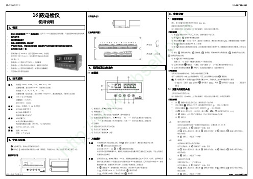
⑤ 设置键
⑥ 巡回检测方式和定点方式切换 ⑦ 定点方式下通道加 1 ⑧ 定点方式下通道减 1,消音
键进入修改状态,通过按
tp :
修改完成后 按 通道数 键存入,并跳到下一参数
3、安装与接线
为确保安全,接线必须在断电后进行。 供电的
4.2 功能操作
定 点 仪表通电时处于巡回显示方式,按 再按 键则返回到巡回显示方式 和 键选择显示通道 键进入定点显示,通道显示器的个位闪烁
修改完成后 按 键存入,并跳到下一参数
第 2 报警点报警灵敏度 设置内容详见 6.4,出厂设置为 0 若不设该参数,按 按 键跳到下一参数。否则
w
键进入修改状态,通过按
修改完成后 按 键存入,并跳到下一参数
om
说 明 原 理
6、功能及相应参数说明
6.3 冷端补偿
热电偶产生的 mV 值反映了工作端与参考端(冷端)的温度差,需要进行冷端补偿后才能得到工 作端的实际温度。根据实际接线情况,有两种补偿方式。 补偿后的 mV 值 = 热电偶产生的 mV 值 + 冷端温度对应的 mV 值 例如:S 分度号热电偶产生 9.587mV 的信号,表示工作端与冷端的温度差为 1000℃,此时冷端 温度为 30℃,对应的 mV 值为 0.173mV。则补偿后的 mV 值=9.587+0.173 = 9.760mV。对应的 温度为 1015℃,即工作端的实际温度 热电偶的补偿导线直接连到仪表端子。冷端温度即为端子处的温度。仪表通过端子处的测温元 件测出温度,并自动进行补偿。如果将信号输入短路。仪表显示的值应为端子处的实际温度 仪表出厂时已按该方式设置,并经过检验 参数必须设置为 0061 参数为冷端补偿修正。如果认为冷端补偿有误差,可通过该参数进行修正。该参数的值增 大时,补偿的温度增加,该参数的值减小时,补偿的温度减小 热电偶的补偿导线接到恒温装置,冷端温度为恒温装置的实际温度 参数应设置为恒温装置的实际温度 参数必须设置为 0
多路巡检仪说明书
报警输出:继电器控制输出—AC220V/2A、DC24V/2A(阻性负载) 馈电输出:DC24V±1,负载电流≤50mA 通讯输出:RS485/RS232通讯接口,波特率1200~9600bps可设置,采用标MODBUS RTU通讯
显示为量程下限值。(此功能只针对电压、电流信警通道————报警输出继电器,共有2个,每个输出继电器对应16个输入通道
名称
设定范围
统一报警 0~1
报警通道 输入通道 报警方式
1~16 1~16 0~2
报警值 小数点
0~3
报警值
-1999~9999
报警回差 0~9999
出厂预置值 4
设定变送输出的放大比例
0:无小数点心 1:小数点在十位(显示XXX.X) 2:小数点在百位(显示XX.XX) 3:小数点在千位(显示X.XXX) 设定变送输出的下限量程
-6-
五、仪表操作 1.仪表面板配置
名称 确认键
内容 选择菜单时,用于确认菜单中的选择项 修改参数时,用于确认新设定的参数值 画面显示时,配合“▲”键可进入组态菜单页 显示历史数据时,用于确认下一步要修改追忆时间 设定参数时,配合“ ”键用于移动小数点的位置
选择菜单时,用于光标下移
修改参数时,用于减少光标指定处的数值 光标下移键 测量显示时,用于不同通道之间显示画面的切换 操
0~10mA开方
-9999~99999
4~20mA开方
-9999~99999
温度巡检仪快速调试说明

1、2、 仪表面板如下图所示:PV SV ALM1/AL SET① 巡检状② 巡检状③ 在一级控制参数(一PV 测量值SET 键可进入部分一级参符号 CLK AT1 -H01 HA01 -L01 LA01 ……-H16 第HA16 第-L16 第LA16 第 : :巡检状:巡检状LM2 :第一/第:功能键状态下,按SET 状态下,按SET 级参数CLK=132一级参数)设定值显示状态下,入当前参数修改参数如下: 名 巡检间第一通道上限第一通道上限第一通道下限第一通道下限…第十六通道上第十六通道上第十六通道下第十六通道下状态下显示测量状态下显示通道第二报警灯,报键键小于2秒通键5秒可进入,先按SET 键定按SET 键5改状态,修改完称 隔时间 限报警目标值 限报警目标值 限报警目标值 限报警目标值…限报警目标值限报警目标值限报警目标值限报警目标值温度巡量值,参数设定道号,参数设定报警时灯亮。
通道进入锁定状入一级参数查询不放,再按增加秒,仪表进入完成后按SET 键设定全全全全全全全全巡检仪快速定状态下显示参定状态下显示参状态,结合增加询,在查询状态加键5秒可进入一级参数查询键确认返回。
定范围全量程 显全量程 全量程 显全量程 ……全量程 显全量程 全量程 显全量程速调试说明参数符号 参数设定值 加键和减少键可态按SET 键5秒入二级参数各询状态,按增减CLK=1每一显示第一通道上显示第一通显示第一通道下显示第一通显示第十六通道设显示第十六显示第十六通道设显示第十六明可锁定需要的通秒可回到巡检状通道查询。
减或减键即照下说明32时可修改参一通道显示时间上限报警的报警定下限报警通道上限报警的下限报警的报警定上限报警通道下限报警的……道上限报警的报设定下限报警 通道上限报警道下限报警的报设定上限报警 通道下限报警通道,再按SET 状态。
下表顺序变换参参数 间警设定值可设的回差值 警设定值可设的回差值报警设定值可的回差值 报警设定值可的回差值T 键可回到巡检参数,需要修改出厂预定132 502 502 ……502 502检状态。
温度巡检仪说明书

TCD16/48温度巡检仪使用说明书武汉华工电气自动化有限责任公司2001年7月一. 名称与编号1.产品名称:16/48路数字温度巡检仪2.产品型号:IET-TCD16/483.软件版本号:TCDV2.0二. 用途与性能1.用途:数字温度巡检仪适用于电力、化工、石油、冶金及其它生产过程中,对传感器为热电阻的温度参数进行巡回检测、越限报警及参数显示。
2.性能:(1)(2)热电阻线制:①三线制②二线制,不配线路电阻(3) 故障显示:①热电阻空载显示----。
②热电阻正溢出(过量程)显示HHHH。
③热电阻负溢出显示LLLL。
(4) 测量精度:±0.5%(5)分辨率:热电阻0.1℃(6)报警方式:有测点越限时,点亮对应越限指示灯,同时吸合继电器,越下限或越上限1,接通越限报警继电器;越上限2,接通事故报警继电器。
保持,直到所有测点回复正常,,熄灭越限指示灯,继电器返回。
三.硬件原理框图和软件流程图图1 硬件原理图图2 软件流程图四.机箱外观视图1.机箱在屏柜上开孔尺寸为(mm):202×86(宽×高),机箱尺寸如下图:EtRt2. 背视图背视图说明:① 32~47路信号线插头(孔) ② 16~31路信号线插头(孔) ③ 0~15路信号线插头(孔) ④ 报警输出插头(孔) ⑤ 通讯接口插头(针) ⑥ 电源开关 ⑦ 电源插座3.正视图正视图说明:①点序位:用于显示测点序00~47,整机设定点序为P0。
②参数位:用于显示分度号,线制,线路电阻,上限1、上限2、下限报警值,温差等。
③L0~L47 :用于指示当前接有信号的通道。
④工作状态功能指示灯,从左至右依次为:·功能指示灯点序N:闪烁为点序,平光为接入信号为热电阻测量信号。
·功能指示灯分度S:闪烁为分度。
·功能指示灯线路电阻阻C:当分度号是热电阻时,闪烁时可按“ ”或“ ”将某点线路电阻在参数位上显示出来。
温度巡检仪说明
备忘:一、一、 概述概述二、二、 技术规格技术规格三、三、 仪表使用注意事项及仪表维护四、四、 仪表外形仪表外形五、五、 仪表接线仪表接线六、 仪表面板及操作说明(一)、 面板说明(二)、 操作说明七、七、 仪表参数说明(一)、 参数速查表(二)、 参数详细说明 1、 报警参数AH**、AL** 2、 线型输入标定参数dH**、dL** 3、 输入修正参数Sc**与增益修正参数Fi** 4、通讯参数Addr和bAud (兼作打印时间设置参数) 5、 巡检间隔时间参数L_ti 6、 巡检软件点数设置参数CH目 录录145669910111113141515131415 7、 回差参数dF** 8、 仪表功能定义参数ALP 9、 输入规格参数Sn 10、 小数点位置参数dP** 11、 打印间隔时间P_ti 12、 冷补修正参数CSC八、八、 仪表与TP系列打印机接口九、 常见问题解答十、十、 仪表抗干扰说明161719202122161919 XMX系列智能多点巡检仪一、概述(一)主要特点 ▲ 采用先进的ASIC芯片及技术制造,减小体积,并提高可靠性及抗干扰性能。
▲ 输入采用数字校正系统,测量精确稳定,可扩展使用任意分度号的非线性传感器,消除了温漂和时漂引起的测量误差。
▲产品有多种规格可选,标准规格有八点、十六点和三十二点三种。
▲ 按国际标准制造,具备100-240VAC宽范围输入的开关电源及WATCHDOG功能。
在强干扰环境下也能保持精确的测量及稳定的工作。
▲ 仪表接线全部采用进口高品质接线端子,接线方便、牢固。
▲ 仪表的巡检点数可任意设定。
不用的点在自动/手动巡检过程中可自动跳过。
▲ 仪表的两个公共报警输出可以任意配置成多种报警方式,上下限、上上限或下下限。
▲ 面板尺寸为160×80mm,上排显示数码管为0.8英寸高亮大数码管,还可选配液晶显示。
▲ 仪表接热电阻输入时,采用三线制接线,消除了引线带来的误差;接热电偶输入时,仪表内部自带冷端补偿部件;接电压/电流输入时,对应显示的物理量程可任意设置。
温度巡检记录仪用户手册

TOPCITY---Temperature Profiling for IndustryTOPCITY ELECTRONICS CO.,LTD重要注意事项和安全信息感谢您选用TC smart系列温度曲线测试仪,该仪器是特别为波峰焊锡机、回流焊配套的在线式测温装置,具备波峰焊﹑回流焊两用功能,具有0.05S~600S之间12000种可选择的采样速率,每通道可记录数据120000点,配合计算机软体的后台分析功能即可进行温度曲线与生产工艺的考量;在线式设计,免除离线式分析仪的困扰。
被电子生产企业广泛用于贴装和插件PCB 焊接工艺的考量,同时也适用于其它行业的温度测绘(如食品、冶金、汽车、环境、涂装、烤炉、隧道炉……)。
使用此温度曲线测试仪时,必须遵守这些安全注意事项,以免发生安全事故和损坏仪器。
1、在使用或操作此设备之前,请仔细阅读和理解本手册。
2、非本仪器维护人员和未经培训合格的人员切勿随意使用本仪器。
3、第一次使用仪器时,请先除去仪器和托架保护盒上的保护膜。
4、仪器使用时必须置入托架保温盒内,并保证保温盒完好无损,以免高温损坏仪器及引发事故。
5、仪器属高温传导体,操作使用时应注意人身及设备安全。
6、本仪器应在洁净的环境中使用, 裸露金属不能接触带电物体。
7、请不要在露天、高温多湿的条件下直接使用、存储仪器。
8、请不要在强静电、电磁干扰源附近使用本仪器。
9、检修时,请关掉电源,以防损坏元器件。
10、使用或存储仪器时应保持平稳,不得有倾斜或不稳定现象,以防止仪器滑落。
11、仪器内电压不足时仪器报警指示灯被点亮成绿色,须及时充电,以确保仪器正常使用功能。
12、仪器使用后,请及时将仪器放回仪器箱内,以免意外损坏仪器。
13、该仪器可在-25℃~55℃的范围内被运输及保存。
在运输过程中,请尽量避免过高的湿度、振动压力或机械冲击。
14、本仪器属于精密设备,请勿随意拆装。
15、请保存好本使用手册,以便日后保养、维护检修时使用。
sre 16b巡检仪 说明书
sre 16b巡检仪说明书
温度巡检仪使用说明
温度巡检仪,以微处理器(单片机)为核心设计,拥有多个通道,采用最先进的“1-wire”总线技术,每个通道可以检测1-8个温度点,最多可巡检64个温度点,大大减少了系统的电缆数量。
电缆数量少,施工方便,调试简单。
采用模块化结构,安装、维护方便。
接线说明
1、温度巡检仪可采用宽电压输入(9~32V),建议采用DC 12V电源保证其长期工作的稳定性。
所有操作均为不带电操作,各组件连接完善后方可供电。
2、温度巡检仪提供RS485输出接口,接线时,注意正负级。
不可将电源误接至通讯端子上,否则会造成元器件损毁(不在保修范围内)
温度巡检仪的应用
1.温度巡检仪在检测、认证行业中的运用
随着中国进入WTO,国家对商品的质量、安全等要求也越来越严格。
如家电产品要在市场上流通,就必须通过3C认证。
因此各大检验局或者认证中心必须按照国家规定的标准来进行检测,温升检测就是其中比较重要的一项。
2.温度巡检仪在家电行业中的应用
其实这个行业跟检验或者认证行业有直接关系。
如果,家电产品要送到检验局去检测,那最好的办法就是按照检测局的标准来做,一是用检测局使用检测标准,二是用检测局使用的仪器。
3.温度巡检仪IT行业中的应用
IT,一个检测标准最为繁多的行业。
如果家电都需要做温升检测,那IT业肯定也是需要的。
4.温度巡检仪在食品储运中的运用
由于食品储运过程时间并不是一个短期问题,但食品保存中的相对平衡湿度又是保证食品安全的一项重要指标,相对平衡湿度直接影响菌落的生长。
巡检仪使用说明书(无校准)
16通道智能巡检仪使用说明书特点:1、1-16通道数可选择(即可屏蔽2-16通道中的任何一个通道);2、各通道输入类型可任意设置(通过软件设置和硬件跳线相结合的方式完成);3、各通道可根据需要分别设置小数点位置和显示范围;4、多种报警方式可选择:16通道相同输入类型情况下可实现集中设置报警值统一继电器输出、独立设置报警值统一继电器输出、独立设置报警值独立继电器输出;16通道不同输入类型情况下可实现独立设置报警值统一继电器输出、独立设置报警值独立继电器输出;分别报警由副机完成;5、多种变送输出类型和方式可选择:可选择输出0-10mA、0-20mA、4-20mA信号;可选择所有通道测量值的平均值、最大值、最小值变送输出;可指定16通道中任何一通道进行变送输出;所有输出方式的变送范围均可设置;6、采用双排四位数码管显示方式,每通道采用双色指示灯指示报警状态,红色亮表示上限报警,绿色亮表示下限报警;7、具备手动巡检功能,可手动查看各通道测量值;8、具备485通讯输出,采用标准modbus协议,通用性强,可靠性高;设置方式:长按SET键(2秒)即可进入设置菜单,增加键∧、减小键∨修改参数值,SET键确认并保存参数值,同时跳至下一菜单,按MAN键可回到上一个参数,同时按SET键和MAN键即可退出设置状态;在设置状态下如50秒无按键操作,即自动退回测量状态;参数设置表Sn代码表:[表二报警指示:在巡检仪面板上有16只双色指示灯,用于各通道报警状态显示,即任意通道有上限报警信号时,其对应通道的指示灯红灯亮,统一报警时上限报警继电器吸合,分别报警时对应通道的上限报警继电器吸合;有下限报警信号时,对应通道的指示灯绿灯亮,统一报警时下限报警继电器吸合,分别报警时对应通道的下限报警继电器吸合,若没有报警信号则指示灯不指示。
统一报警时,16通道中任何一通道进入报警状态,即相应的报警继电器吸合,例如第2通道有上限报警信号时,仪表上限报警继电器即吸合,如果有多个通道同时有报警信号存在,则只有当所有通道的报警信号解除后相应的继电器才释放。
XSLE系列高精度温度巡检仪说明书

XSLE系列高精度温度巡检仪说明书
说明:
①输入信号热电阻 PT100或PT1000,必须4线制,-200.00℃~+200.00℃热电偶分辩率 0. 1℃,
准信号(4-20)mA等
②精度±0.05%F.S
③外形尺寸:160×80(最多16通道)、160×160(最多40通道)、250×250(最多64通道)
④检测速度 0.2s/每通道
⑤ 2点公用报警
⑥仪表电源 220V AC
基本配置:
160×84,8通道
160×160,24通道
250×300,48通道
扩展功能:
①通讯接口:RS 232或RS 485
②打印机接口(不含打印机单元)
③扩展2点公用报警
选型表
内容代码及说明
XSLE/ 2点公用报警
外型尺寸A—横式160×84×182
C—方形160×160×180
D—台式250×300×250
通道数□□横式8通道到16通道
□□方形24~40通道
□□台式48~64通道
通讯接口S0 无通讯接口
S1 RS-232接口
S2 RS-485接口
打印功能P0 无打印
P1 分体打印
仪表供电V0 220V AC
V1 9V-24VDC
V2 其它
非标功能N N表示非标准功能。
XSL16温度巡检仪英文版
SUZHOU SURPON INSTRUMENT CO.,LTDADD:F6hengfeng building,NO.26-6North Tongjing Road. Suzhou,Jiangsu province china Fax :0086-512-68381803SUZHOU SURPON INSTRUMENT CO.,LTD ADD:F6hengfeng building,NO.26-6North Tongjing Road. Suzhou,Jiangsu province china Fax :0086-512-68381803 11、GeneralSPB-XSL16 Series applies to measure, alarm and retransmit 2-16 channel signals of thermocouple and RTD. Ø Basic intrinsic error is less than 0.2%, indication range is -1999~9999. Ø The signal type, range, alarm value of each channel can be set separately.ØDigital filtering time coefficient of each channel, which can improve anti-interference ability, can be set separately.ØZero and full scale rectification, which can effectively reduce sensor errors to improve measuring accuracy, can be set separately.Ø Channels unused can be shut at will.SUZHOU SURPON INSTRUMENT CO.,LTD ADD:F6hengfeng building,NO.26-6North Tongjing Road. Suzhou,Jiangsu province china Fax :0086-512-68381803 2SUZHOU SURPON INSTRUMENT CO.,LTD ADD:F6hengfeng building,NO.26-6North Tongjing Road. Suzhou,Jiangsu province china 32、Technical SpecificationsInput RTD :Pt100,Cu100,Cu50,BA1,BA2,G53. Display solution is 0.1℃ for full range and disconnection identification is available.Thermocouple :K ,S ,R ,B ,N ,E ,J ,TDisplay solution can be set to 1 or 0.1℃℃ for full range (negative temperature included) anddisconnecting identification is availableAccuracy 16-bit A/D converterMeasuring Accuracy :±0.2%F·SDisplay Resolution :1/10000Rate200ms per channel (related to parameter )Display 2-digit LED channel number display 4-digit LED measured value displayAlarm state indicator of all channels Alarm 3 mode of alarm 2 public relaysRelay contact capacity: 250V AC ,2A (resistance load ) Power160V AC~260V AC ,50HzCircumstance Temperature :0~50℃℃Humidity :≤90%R·HSUZHOU SURPON INSTRUMENT CO.,LTD ADD:F6hengfeng building,NO.26-6North Tongjing Road. Suzhou,Jiangsu province china43、Installation and WiringFor the sake of safety, turn off the power supply before wiring.The terminalis a common terminal of power filter, with high voltage, which can only be connected tothe earth and connecting with other terminals is FORBIDDEN . Installation 【Dimensions 】【Cut-out Dimensions 】【wiring 】InputRTD:If the input signal is 2-wire, B and C should be shortcutting. Thermocouple:SUZHOU SURPON INSTRUMENT CO.,LTD ADD:F6hengfeng building,NO.26-6North Tongjing Road. Suzhou,Jiangsu province china 5Anode should be connected to A of the corresponding channel, while the cathode should be connected to the B of the corresponding channel.Input signal shielding layer can be connected to C .4、Faceplate & Keys4.1 FaceplateDisplay① Channel window : If the 2nd digit is flashing, the MVW is at fixed mode. ②Measured value window (MVW).③Alarm indicators: The first and the second alarm state of the current channel④Alarm indicators of each channel. The lights have three states : On—the current channel is in alarm. Off – the current channel isn’t in alarm. Glint-- the current channel is just in alarm.⑤Set Key⑥Mode key⑦Increase key⑧Decrease key,silenceKey is used to enter modifying state, move decimal point and display value of parameters coordinatelywith the other keys.SUZHOU SURPON INSTRUMENT CO.,LTD ADD:F6hengfeng building,NO.26-6North Tongjing Road. Suzhou,Jiangsu province china 64.2 Operation of function Circuit mode and fixed modeWhen the instrument is power on, it is in state of circuit measuring and display, which means to display thevalue and the number of each channel in turn, hereafter called “circuit mode ”, and it can be shifted to “fixed mod e”, which means to display only the number and the value of a chosen channel .To presskey in circuit mode can enter fixed mode, and the second digit of channel display is flickering, topress the key again can return to the circuit mode. In fixed mode, the channel can be chosen by changing the number of channels through pressingorkey.The instrument measures the value of each channel in a constant span of time and dose not affects normalmeasurement of the other channel even in fixed mode.5、Parameter Setting5.1 Alarm Value setting-- Set value of the first alarm-- Set value of the second alarmThe two parameters above are not controlled by security code.If no key is pressed for more than 50 seconds after entering setting state, the instrument will automatically exit setting state. 【Setting Steps 】① Presskey to enter fixed mode. The ones of the number in channel window is flickering. ②Pressorkey to select the channel needed to set.③Hold downkey for more than 2 seconds till entering setting state. The channel window displaysandMVW displays the channel number. Press ④key to choose AH or AL of the selected channel.⑤ Presskey to call out the initial value of the parameter. AH or AL is displayed on the channel windowand its value is displayed on MVW. The flashing digit is the one to be modified. ⑥Presskey again to shift the digit and usekey to increase orkey to decrease value to the onewanted.key has carry function,key has borrow function.⑦Presskey to confirm the modificationSUZHOU SURPON INSTRUMENT CO.,LTD ADD:F6hengfeng building,NO.26-6North Tongjing Road. Suzhou,Jiangsu province china 7Repeat steps ④ ~ ⑦ to set the second alarm set value of the selected channel.⑧ After step ⑦, press key to shift to the next channel and repeat steps ④ ~ ⑦ to set the parameters ofthe channel.⑨ After step ⑦, hold down key till the instrument exits setting state and returns to measuring state.【Duplication of Parameters 】Using the function of parameter duplication can reduce the works in parameter setting.If a parameter value of the next channel is the same with the one of current channel, press key at the step④ to copy that value.Example :If allneed to be set to 80.0 from channel 1 to channel 16, setof the 1st channel as abovementioned steps at first. Whileis displaying, presskey,is displayed and press keyagain,is appeared ……, in thissequence, tillis displayed on measuringwindow, the setting is done.5.2 Settings of Configuring ParameterPublic Configuring parameters are controlled by security code.In process of setting parameters, if no key is operated for more than 1 minute, the instrument would automatically exit setting state. 【Steps 】—Presskey to enter the fixed mode. The ones of channel number will be flashing.—Hold downkey for more than 2 seconds till the channel number is changed toto enter settingstate.— Hold downthe key for more than 2 seconds again tillis displayed whereas the instrument is insecurity code setting. —Pressto enter state of modification. Set the value to 1111 by pressing,orkeys.—Presskey to conform the setting and the security code is set. The public configuring parameters canbe set then. —Press key each time, the configuring parameters is displayed orderly.Presskey to enter modification state and the final digit is flashing. Useandkeys to modify the value to needed one.Presskey to save the value after modification and the next parameterappears automatically.SUZHOU SURPON INSTRUMENT CO.,LTD ADD:F6hengfeng building,NO.26-6North Tongjing Road. Suzhou,Jiangsu province china 8If modification of current parameter is no necessary, presskey to move to nextparameter.-- Time span of displaying.The setting range is 0.5~10.0 (seconds).It is the time span of display for each channel in circuit measuring state.--Channel number--Mode of cold junction compensationCoefficiency of cold junction compensation Alarm type of the 1st alarmThe default setting is— Upper limit alarm—Lower limit alarmAlarm type of the 2nd alarmThe default setting is— Upper limit alarm—Lower limit alarmAlarm hysteresis of the 1stAlarm. The default setting is 0. (See details in 6.4) Alarm hysteresis of the 2ndAlarm. The default setting is 0. (See details in 6.4) Silence delayThe default setting is 10【Exit 】As only parameter sign is indicating, hold down key till to exit setting state..3 Configuring Parameter Setting of All ChannelsConfiguring parameters of all channels include::Zero rectification. For more detail see Chapter 6.2. :Full scale rectification. For more detail see Chapter 6.2. :Selection of Input signal. For more detail see Chapter 6.1.:Decimal point position of measured value. For more detail see Chapter 6.1. :Time co efficiency of digital filtering. For more detail see Chapter 6.1.SUZHOU SURPON INSTRUMENT CO.,LTD ADD:F6hengfeng building,NO.26-6North Tongjing Road. Suzhou,Jiangsu province china 9Configuring parameters of all channels are controlled by security code. These parameters are in the same group as the alarm set value and can be set according to the Chapter 5.2 after the security code is set.6、Illustration on Functions & Corresponding Parameters6.1 Input Signal & displayParameters F ollowing Parameters should be correctly set, otherwise the instrument cannot work properly.Parameters of a channel are independent to the other channels’ and should be set one by one according toeach channel. If information about input signal on ordering is integrity, the related parameters would be set accordingly before the instrument is delivered.(For setting referred to Chapter 5.2.)Selection of Input signalsSelection should be in accordance with the actual input. The value of a parameter is expressed in a formof symbol. The following list shows the corresponding relations:No. SignsInput Signal0 Not in use.1 RTD Pt100,full scale2 RTD Cu100,full scale3 RTD Cu50,full scale4 RTD BA1,full scale5 RTD BA2,full scale6 RTD G53,full scale7 Thermocouple K ,full scale (negative temperature included ) 8 Thermocouple S ,full scale (negative temperature included ) 9 Thermocouple R ,full scale (negative temperature included ) 10 Thermocouple B ,full scale11 Thermocouple N ,full scale (negative temperature included ) 12 Thermocouple E ,full scale (negative temperature included ) 13 Thermocouple J ,full scale (negative temperature included ) 14Thermocouple T ,full scale (negative temperature included )Selection for decimal point position of measured valueSUZHOU SURPON INSTRUMENT CO.,LTD ADD:F6hengfeng building,NO.26-6North Tongjing Road. Suzhou,Jiangsu province china10 RTD input channel: The only selection is 000.0 Display resolution is 0.1℃.Thermocouple input channel: Both 0000 and 000.0 can be selected, display resolution is 1℃ for0000 and is 0.1℃ for 000.0 , which the maximum range is 999.9℃.For thermocouple B, S, T, R, the displaying value may be fluctuate because the input signal is too small.Therefore the 0.1℃ mode is not recommended in these circumstances.Time coefficiency of digital filtering (1 to 100)Digital filtering can reduce fluctuation of indicated value caused by input fluctuation and interference.The larger the setting value of is the greater the effect will be and the slower the reaction of theinstrument to the change of the input signal is.6.2 Zero and Full Scale CorrectionIllustration There would be errors in measurement of a specific engineering value due to variety of factors fromsensors, Retransmitted output and instrument itself, with usage of the rectification could reduceeffectively the errors and improve the accuracy of measurement and control for the whole system.Formula:Rectified Value =×(Measured Value before rectified+) Parameter—— Zero rectification—— Full Scale rectificationSteps①Before correction, make the channel be unmodified state by settingof the channelto be 0000 and to be 1.000.② Process the zero rectification.③Process the full scale rectification.Example: Input : Pt100 -- measuring range is 0~200.0℃The actual temperature of the 1st channel should be 0.0℃, because of the sensor error, the indication is0.8℃. set of the 1st channel to be -0.8, then the indication is modified to 0.0℃. 6.3 Cold Junction CompensationIllustration The voltage(measured in mV) created by thermocouple reflects the temperature difference between workingterminal (the pot measured )and reference terminal(the cold terminal). Because reference terminal has its owntemperature, the actual temperature should be the temperature difference mentioned before adding thisreference temperature, which is called cold junction compensation.There are 2 compensation types according to actual wiring.SUZHOU SURPON INSTRUMENT CO.,LTD ADD:F6hengfeng building,NO.26-6North Tongjing Road. Suzhou,Jiangsu province china11 Principle Compensated V alue (mV) =V alue (mV) created by thermocouple + V alue (mV) corresponded to the ColdJunctionFor example: Thermocouple S creates 9.587mV signal, which means the temperature difference betweenworking terminal and cold junction is 1000℃. At this time the cold junction temperature is 30℃, thecorresponding mV value is 0.173mV .Then the compensated value = 9.587 + 0.173 = 9.760mV . The corresponding temperature is 1015℃,which is the actual temperature of the working terminal.Type 1 The compensation leads of thermocouple are directly connected to the instrument terminals.T he cold junction temperature is just the instrument terminal temperature. The instrument measurestemperature through thermoscope at the terminal, and the compensation is automatically done. Ifshortcut the input terminals, the indicated value should be the actual temperature of the terminals.The instrument is set according to this mode before delivering and is checked.must be set 0061.is the cold junction coefficient. If there are errors after cold junction compensation, modification can be done by using thisparameter. By Increasing or decreasing the value of this parameter, the compensated temperature gainsor reduces accordingly.Type 2 The compensation leads are connected to a constant temperature device, the cold junction temperature isthe actual temperature of this device.must be set to be the actual temperature of the device.must be set to be 0.6.4 AlarmIllustration Alarm is the reaction of the indicator and output relay of the instrument when measured value exceedsthe set range. Alarm includes 4 factors which are set value, alarm type, alarm hysteresis and output modeof relays.Parameter——Set value of the 1st alarm ,independently setting for each channel.——Set value of the2nd alarm ,independently setting for each channel.——Alarm type of first alarm for all channels.If the setting ismeans upper limit alarm.If the setting ismeans lower limit alarm. ——Alarm type of second alarm for all channels.SUZHOU SURPON INSTRUMENT CO.,LTD ADD:F6hengfeng building,NO.26-6North Tongjing Road. Suzhou,Jiangsu province china12If the setting is means upper limit alarm.If the setting ismeans lower limit alarm. Bysettingand , the instrument can conduct upper or lower limit alarm, upper-upperlimit alarm and lower-lower limit alarm——Alarm hysteresis of 1stalarm for all channels——Alarm hysteresis of 2ndalarm for all channels——Silence delay . range : 0~51. The state of Alarm indicators and alarm type is decide by theparameter.Output ModeFor an instrument of 2 relays of alarm, there are 3 acting modes by setting(Defaulted setting is 1) 1is set to 1~50 .this mode will clue on time.RL1 : any of channel is on alarm, RL1 is on . Auto delay resume or by thekey resume, the delay time is set by. range 1~50 second.2is set to 51 . The same as the first mode .but RL1 can’t be auto delay resume , only by the key resume 3is set to 0 .RL1 only the first alarm of each channel is in alarm state, the relay will be on.RL2 only the second alarm of each channel is in alarm state, the relay will be on.Alarm indicatorsEvery channel have own Alarm indicators, the lights have three states : on, off and glint.Glint – The current channel is just in alarm. when RL1 resume, the light will be on from glint,On – The current channel is in alarm. Off – The current channel isn’t in alarm.。
TDS-163277温度巡检仪使用说明

16路智能数字巡回检测控制仪说明书中华人民共和国制造计量器具许可证西安蓝田恒远水电设备有限公司TDS-1600是16路系列数字巡检控制仪。
采用单片机技术,接入热电阻等信号,可进行16路以内的数字巡回检测和控制。
主要特点有:1、自动循环显示被测量值、巡检路数、已报警的通道号。
2、定点/巡检选择,定点状态可用手动切换至任意显示通道。
3、可在16路范围内任意消隐不使用的巡检通道。
4、每路巡检时间在1.5-10秒之间可任意设定。
5、各巡检通道可设置各自所需的报警值,共用2-3个继电器报警。
6、电站如用:TDS-243PC77可对Cu50、Pt100自动识别、也可以混合使用。
7、WATCH DOG监控技术防死机,数字滤波技术增强抗干扰能力。
8、E2PROM数据保护,所有设定参数断电不会丢失。
9、仪表取消了电位器调试,精度调校,只需在仪表盘面上进行。
10、具有自动校零系统,使仪表不会随环境温度及时间的变化而造成的数字漂移。
11、与上位机联网机型选用RS422、232、485(Modbus)通信接口输出。
二、主要技术指标1、巡检路数:16路范围内2、工作环境:温度范围0~50℃;相对湿度≤85%3、工作电源:220V AC±15%;50Hz±2Hz4、量程范围:0.0—150.0℃5、精度等级:±0.5%FS±1个字6、显示方式:右2位0.5〃LED;中间4位0.8〃LED;左2位0.5〃LED7、报警显示:中屏显示实测值,右屏循环显示已报警的通道8、报警功能:断阻报警显示A—A,超下量程显示L—A、超上量程显示H—A,若超设定报警值,相应指示灯亮且继电器动作9、控制设定:全量程范围内可统一设定或分别设定10、接点输出:3A/220V AC11、巡检时间:每路1.5-10.0秒之间任意调整,步进1增减0.1秒12、开孔尺寸:152×76mm13、外型尺寸:240×80×130mm240×80×250mm14、功率消耗:≤8W15、仪表重量:≤1~2Kg三、仪表型号TDS—161600系列0系列3温度1压力4液位2流量F其他0系列1热电偶分别用B、S、R、K、N、E、J、T等分度号填写2Pt100L Pt10M Pt503Cu50G Cu100PC Pt100、Cu50在0-150.0℃范围内自动判别F其他0系列(无报警控制)1上限(一个继电器控制)2下限(一个继电器控制)3上下限(二个继电器控制)4双上限、断偶、断电(四个继电器控制)5双上限、断偶(三个继电器控制)6双上双下(二个继电器控制)7双上限,断偶与上限共用(二个继电器控制,)8双下限(二个继电器控制)F其他0系列(或无输出)2RS2327RS4858RS422F其他输出0AC220V240×80×130数码管0-150℃1AC110V2DC220V96×96×1203DC110V液晶6开关电源240×80×250TDS—16表型输入报警信号输出—电源外型尺寸显方式量程TDS—163277—0000 TDS—163PC58—6600例1:24路数字温度巡检仪表,输入Pt100,双上限报警,RS485通信接口,电源AC220V,外型尺寸240×80×130横式,数码管显示,量程0~150℃。
XWD温度巡检仪使用说明书
XWD系列智能型巡检仪重庆华源水电技术工程有限公司一、 概述XWD智能型巡检仪是以微处理器为核心设计,并广泛吸收了国内外同类产品的各种优点。
具有自校零、自校量程功能,免去用户校正仪表之苦。
仪表的关键器件采用美国INTEL公司、ATMEL公司、MAXIM公司等公司产品,在干扰防护上采用阻容滤波网络,有源滤波,软件滤波等多种抗干扰措施,使得仪表有很强的抗干扰能力。
二、 主要特点1、每个通道的输入信号种类,起始测量值和终止测量值,小数点显示位置可通过面板任意设定,对热电阻输入的品种,可混合使用二线制、三线制。
2、各通道可以独立设置上、下限报警方式、报警值。
3、如果该测量通道不用,可以通过设置取消,如果想要恢复也可设置恢复。
4、软件设置、软件校正,机内无任何调整电位器抗震性好。
5、可带RS-232、RS-485、RS-422等串口与主叫方通讯,也可带4-20mA等标准直流电信号输出。
6、完善的程序监控电路,电压监测保护电路,以多重冗余技术,确保仪表稳定运行。
三、 产品型号及意义说明:1、直流电信号输出只能通过面板设置某一点带输出或者巡检到的点(面板显示的点)有输出。
2、本仪表带2个继电器输出,2个继电器的报警方式可以任意设定。
3、仪表分三类:a、热电偶输入型。
b、热电阻输入型。
c、其它输入。
仪表输入信号在同一类中可以任意设定。
四、 主要技术指标1、检测通道:4-64点2、精度:0.5级3、报警设定范围:全量程4、巡检速度:1-255秒(指面板显示巡检速度)5、输入阻抗:热电偶输入大于1MΩ; 4-20mA小于等于250Ω6、输入信号及测量范围见表17、外线电阻:热电偶输入不大于1KΩ;热电阻输入不大于50Ω8、调节方式:位式调节9、继电器触点容量:交流无感负载220V/3A10、输出(可选):(1)直流电信号输出(2)微机串口输出(RS-232C、RS-485、RS-422)11、冷端补偿范围:0-50O C12、冷端补偿元件:Cu50(铜热电阻)13、使用环境:环境温度:0-50O C;环境湿度:≤85%;大气压:86-108Kpa14、功耗不大于5W15外形尺寸:长×宽×高=160×160×80mm表一:输入类型、测量范围及编码输入信号 代码 测量范围 分辨力K 00 0-1300O C 1 O CE 01 0-800O C 1 O C2.“设置”键:当仪表处于测量状态时,按动此键,仪表就转入设定状态,当仪表处于设定状态时,按动此键,仪表功能会自动转换(具体使用,详看后面的参数设定)。
XSL系列巡检仪说明书

XSL系列巡检仪说明书说明:内容代码及说明XSL 8通道,2点公共报警外形尺寸A- 横式160×84×182﹙W×H ×L) B- 竖式84×160×182﹙W×H×L) C- 方形160×160×182﹙W×H×L) D1- 台式,318×104×300D2- 盘装,318×104×300通道数□□尺寸为A,B的仪表最多32通道;尺寸为C、D的仪表最多80通道输入信号(其他输入信号,订货时说明)R 全部通道均为热电阻,仪表内装的分度号包括:Pt100、Cu100、Cu50、BA1、BA2、G53E 全部通道均为热电偶,仪表内装的分度号包括:K、S、R、B、N、E、J、TB 全部通道均为4mA~20mA或1V~5V,0V~5V等电流、电压信号,需在订货时明确电流、电压信号的输入通道X 输入为热电阻、热电偶混用L 输入为热电阻,热电偶,4mA~20mA,1V~5V,0V~5V 混用。
需在订货时明确电流、电压信号的输入通道通讯接口(独立供电,全隔离)S0 无通讯接口S1 RS-232接口S2 RS-485接口打印功能(带硬件时钟)P1 打印接口P2 一体化打印接口(仅限于D型仪表)仪表电源V0 85V AC~265V ACV1 12V DC~36V DC扩展报警功能T T:表示有扩展报警功能,将标准2点扩为4点,没有可省略非标准功能N N:表示非标功能技术规格4 输入4 通道数:5~80通道4 热电阻:Pt100,Cu100,Cu50,BA1,BA2,G53全量程测量,显示分辨率0.1℃,有断线识别功能4 热电偶:K,S,R,B,N,E,J,T等全量程测量(包括负温),显示分辨率1℃或0.1℃,通过参数选择。
有断线识别功能4 直流电流:4mA~20mA,0mA~10mA,0mA~20mA,显示范围-1999~9999,任意设置量程和小数点位置4 直流电压:1V~5V,0V~5V,显示范围-1999~9999,任意设置量程和小数点位置4 热电阻输入导线电阻:20Ω以内4 热电偶输入导线电阻:100Ω以内4 精度4 采用16位A/D转换器4 测量精度:±0.2%F·S4 显示分辨力:1/100004 热电偶冷端补偿精度:±0.2℃,范围0℃~60℃4 速度4 最快100ms / 每通道,与参数相关4 显示4 2位LED通道号显示4 4位LED测量值显示4 各通道报警状态指示灯、通信指示灯4 报警4 3种报警方式4 2点(可扩到4点)公用报警继电器输出4 输出继电器触点容量:250V AC,2A(阻性负载)4 通信4 RS 232或RS 485接口,光电隔离4 仪表地址0~99可设定4 通信速率2400、4800、9600、19200通过设定选择4 配套测试软件,提供组态软件和应用软件技术支持4 打印4 内置硬件时钟,停电不影响走时,自动调整闰年,大、小月。
多路温度巡检仪-设计说明书

来更具有灵活性。
6.
冻结功能:在不需要系统自动巡回检测时,系统就能够定格并且
持续工作在某一种状态下。因此这就需要所谓的冻结功能。在我
们不需要系统工作在自动状态下时,可以通过输入一个开关量,
是系统“冻结”住,从而工作在某一特定的状态下。
可通过按钮开关操控作冻结或切换显示,在单片机实验板台上模拟调试实现。
基本思想:
本次的设计课题是:多路温度巡检仪。课题的基本思想是以简单的微控制
器为核心,以温度传感器(测温范围为: -50℃-+50℃)为基础,通过信号 -电
压变化器,将温度传感器采集到的温度信号转换成可供 A/D转换器转换的 0~5
清零。
12.键盘扫描及参数设定:此分流程主要是检测键盘是否有动作,如果有动作
就将检测到的按键号存储起来,供参数设定使用。参数设定主要是对节拍控
9.
无操作超时返回:如果系统工作在其他功能状态下,而又没有人
员进行操作,这是就需要工作状态被切换到正常的巡回检测状态。
使系统返回到正常的工作状态
10.
实时钟显示及设定:为了丰富系统的功能和增加系统的实用性,
可以在巡回检测的过程中穿插一个实时钟显示,这样可以另系统
在实际应用当中更具人性化,更接近实际应用场合。
V模拟电压,而且可以实现多路温度的采集和变换。经过信号 -电压变换器输出
的0~5 V电压再经过 A/D转换器转换成一个八位的数字量(采集多路温度时,
某一时刻只能有一路被进行转换),然后利用微控制器将这八位数字量进行读
取,再经过一定的数字滤波和软件算法,最终以一定的显示格式在八位数码管
- 1、下载文档前请自行甄别文档内容的完整性,平台不提供额外的编辑、内容补充、找答案等附加服务。
- 2、"仅部分预览"的文档,不可在线预览部分如存在完整性等问题,可反馈申请退款(可完整预览的文档不适用该条件!)。
- 3、如文档侵犯您的权益,请联系客服反馈,我们会尽快为您处理(人工客服工作时间:9:00-18:30)。
、前面板及功能操作
前面板
通道显示,第2位闪烁表示处于定点状态
测量值显示
报警指示灯。
表示当前显示通道第1,第2报警状态
各通道的报警状态指示灯。
有3种状态:亮——表示相应通道处于报警状态;
——表示相应通道不处于报警状态;闪烁——表示相应通道进入报警状态巡回检测方式和定点方式切换
键则返回到巡回显示方式
在定点显示方式下,由
仪表采用轮回间隔测量方式,兼顾定点通道的快速测量及其它通道的正常监测,不会出现非定
键消音
、
按住设置键
键选择该通道的
键移动修改位,键增值,键减值。
将参数修改为需要的值。
键减值有借位功能
重复④
在第⑦步后按住设置键
,则首先按上述步骤设置好第
按住设置键
再按住设置键
键进入修改状态,末位闪烁,通过、、键的配合修改为
键确认,此时密码已设置完成,可对公用组态参数进行设置
键进入修改状态,通过按键增加,修改完成后
键进入修改状态,通过按键增加,修改完成后
键进入修改状态,通过按键增加,修改完成后
键进入修改状态,通过按键增加,修改完成后
键进入修改状态,末位闪烁,通过,
2报警点报警方式,出厂设置为
键进入修改状态,末位闪烁,通过,
1报警点报警灵敏度
键进入修改状态,通过按键增加,修改完成后
2报警点报警灵敏度
键进入修改状态,通过按键增加,修改完成后
键进入修改状态,通过按键增加,修改完成后
按住设置键
再按住设置键
、、键的配合修改为
按住
,.,
——零点修正
,
——第1报警点设定值,各通道独立
通过、
设置为1~50。
这种方式能及时提示有通道进入报警状态
设置为51。
与第1种方式相同。
但RL1继电器动作后不自动延时恢复,只能通过面板键
设置为0。
