3200钻机说明书
ZYW-2000,ZYW-3200钻机标准配置清单
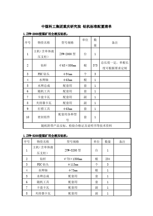
中煤科工集团重庆研究院钻机标准配置清单1.ZYW-2000型煤矿用全液压钻机:
序号物资名称型号规格单位数
量
备注
1 主机(含单体液
压支柱)
ZYW-2000型台 1
2 钻杆¢63×800mm 根375 总长度一定,单根长度可根据要求定制
3 PDC钻头φ94mm 个 3
4 水辫轴φ63mm 根 1
5 水辫总成配套用套 1
6 随机工具配套用套 1
7 卡盘卡瓦配套用副 1
8 夹持器卡瓦配套用副 1
9 打捞工具φ63mm 套 1
10 密封组件配套用各种型
号
套 1
随机附带产品安标、检验合格证及说明书等技术资料
1.ZYW-3200型煤矿用全液压钻机:
序号物资名称型号规格单位数量备注
1 主机(含单体液
压支柱)
ZYW-3200型台 1
2 钻杆¢73×1500mm 根234
3 PDC钻头φ113mm 个 3
4 水辫轴φ73mm 根 1
5 水辫总成配套用套 1
6 随机工具配套用套 1
7 卡盘卡瓦配套用副 1
8 夹持器卡瓦配套用副 1
9 打捞工具φ73mm 套 1
10 密封组件配套用各种型号套 1
随机附带产品安标、检验合格证及说明书等技术资料
ZYW-2000钻机:配泥浆泵BW-250G
ZYW-3200钻机:配泥浆泵BW-250G
防爆开关:QBZ2—120。
钻机使用说明书

钻机使用说明书一、引言钻机作为一种重要的工程机械设备,广泛应用于矿山、隧道、建筑施工等领域。
本使用说明书旨在详细介绍钻机的使用方法和操作注意事项,确保用户能够正确、安全地操作钻机。
二、钻机概述钻机是一种用于钻孔的机械设备,主要由以下组成部分组成:1. 钻机底盘:承载钻机的主要结构,提供稳定的基础支撑;2. 钻杆系统:负责传递转矩和推进力,用于钻孔作业;3. 钻头:用于切削地层和形成孔道;4. 钻进液系统:提供冷却和润滑作用,将产生的岩屑带走;5. 控制系统:控制钻机的运行、监测和保护。
三、钻机的运行方法1. 准备工作a. 检查钻机底盘,确保稳定性,检查底盘润滑情况;b. 检查钻杆系统,确保连接可靠,杆体完好无损;c. 检查钻头,清理切削部分,确认锋利度;d. 检查钻进液系统,保证液位充足。
2. 启动钻机a. 将钻杆系统插入井口,确认连接可靠;b. 打开控制系统电源,按照操作界面指示操作;c. 启动钻进液系统,确保润滑和冷却效果。
3. 钻进操作a. 根据需要调整钻进速度和转速,选择合适的工作模式;b. 当钻杆推进到一定深度后,停止并清理产生的岩屑;c. 按照钻孔计划进行连续的钻进操作。
4. 钻进结束a. 当达到预定的孔深后,停止钻进并提升钻杆系统;b. 关闭钻进液系统,切断电源;c. 清理和检查钻头、钻杆等部件,存放至指定地点。
四、操作注意事项1. 使用钻机前必须熟悉操作手册和安全规范;2. 钻机操作前应检查底盘、钻杆、钻头等部件的完好性;3. 钻进过程中,需定期清理岩屑,确保钻孔质量;4. 在钻进前,应与相关人员沟通,确定井口和井壁的情况;5. 在恶劣气候条件下或出现异常情况时,应停止钻进操作;6. 操作人员应经过专业培训,掌握正确的操作技巧和应急处理方法;7. 钻机维护按照操作手册和维护计划进行,确保设备的正常运行。
五、故障排除在使用钻机过程中,可能会遇到一些故障情况,如有以下情况出现,请按照以下方法进行排除:1. 钻机没有正常启动:a. 检查电源连接是否松动;b. 检查电源线路是否正常;c. 检查控制系统是否有故障。
【精品】大量钻孔机说明书

【关键字】精品大量钻孔机说明书篇一:全自动中心钻孔机操作说明书使用及维护手册全自动圆锯打中心孔专用机HJ.A13027使用前请务必仔细阅读本手册错误操作十分危险操作人员必须熟知并遵守安全规则目录一、设备简介及适用范围 (14)二、结构与功能描述 (5)三、操作流程 (15)四、操作面板及触摸屏说明 (18)五、故障排除方式 (35)六、现场环境及工件要求 (38)附1、电气原理图安全注意事项? 始终遵守安全注意事项可以防止意外事故及潜在危险的发生。
? 在本使用手册中,安全等级分类如下:不正确的操作可能导致严重的人身伤害或死亡。
危险注意不正确的操作可能导致轻微的人身伤害或物体硬件的损坏。
在本说明书中,全篇使用以下两个图标以使你能明白安全注意事项。
在某些确定的条件下可以识别导致人身伤害的危险。
由于危险电压可能已出现,所以应有意识地特别注意。
禁止手伸入。
在某些确定的条件下可以识别潜在的危险。
仔细阅读相关信息并遵守相关指令。
? 为了方便取阅使用说明书,请就近保存。
? 仔细阅读本说明书,使您的设备性能达到最佳化,并确保安全地使用。
1. 设备装卸、安装及接线? 装卸设备注意人生安全,勿以工作台来起吊设备,勿使设备受到撞击。
? 先安装设备,再进行接线,否则,你可能受到电击或其它伤害。
? 安装设备需注意调整每个承重脚均衡承重,并保证机身水平。
? 设备电源为三相AC380V 50Hz,电缆大于10mm×5。
? 2? 不正确的端子接线可能引起设备的损坏。
? 只有受过专业培训的人才可以对设备进行接线和检查。
2. 安全规则? 使用前先对设备各处进行详细地检查,清除异物,保证设备的正常运转; 检查是否满足生产工艺要求,确认无误后开始生产。
? 保养设备时应关断电源,以免意外伤害。
? 生产场地应有良好的通风。
3. 维护,检查与零件更换? 定期检查。
著作权保证本操作手册应作机密处理。
只有经过授权的人员可以使用。
只有经过HONGJI 书面许可,才可以将本档交会第三者。
150型全液压钻机操作规程
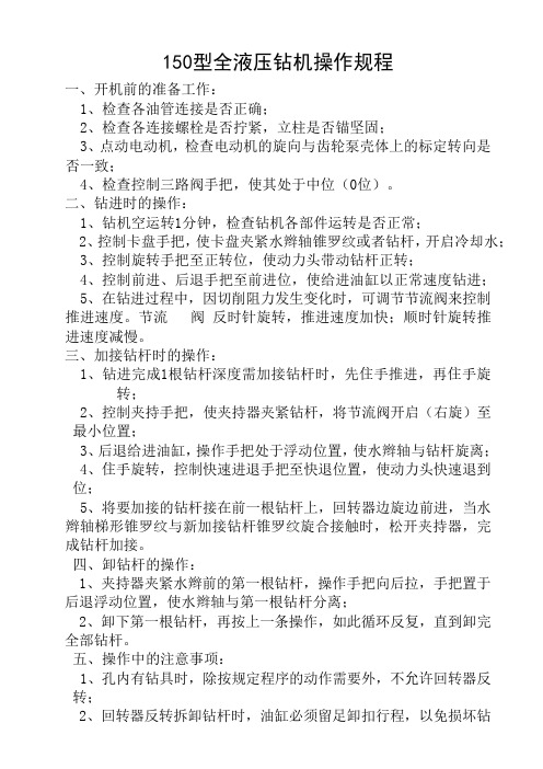
150型全液压钻机操作规程一、开机前的准备工作:1、检查各油管连接是否正确;2、检查各连接螺栓是否拧紧,立柱是否锚坚固;3、点动电动机,检查电动机的旋向与齿轮泵壳体上的标定转向是否一致;4、检查控制三路阀手把,使其处于中位(0位)。
二、钻进时的操作:1、钻机空运转1分钟,检查钻机各部件运转是否正常;2、控制卡盘手把,使卡盘夹紧水辫轴锥罗纹或者钻杆,开启冷却水;3、控制旋转手把至正转位,使动力头带动钻杆正转;4、控制前进、后退手把至前进位,使给进油缸以正常速度钻进;5、在钻进过程中,因切削阻力发生变化时,可调节节流阀来控制推进速度。
节流 阀 反时针旋转,推进速度加快;顺时针旋转推进速度减慢。
三、加接钻杆时的操作:1、钻进完成1根钻杆深度需加接钻杆时,先住手推进,再住手旋转;2、控制夹持手把,使夹持器夹紧钻杆,将节流阀开启(右旋)至最小位置;3、后退给进油缸,操作手把处于浮动位置,使水辫轴与钻杆旋离;4、住手旋转,控制快速进退手把至快退位置,使动力头快速退到位;5、将要加接的钻杆接在前一根钻杆上,回转器边旋边前进,当水辫轴梯形锥罗纹与新加接钻杆锥罗纹旋合接触时,松开夹持器,完成钻杆加接。
四、卸钻杆的操作:1、夹持器夹紧水辫前的第一根钻杆,操作手把向后拉,手把置于后退浮动位置,使水辫轴与第一根钻杆分离;2、卸下第一根钻杆,再按上一条操作,如此循环反复,直到卸完全部钻杆。
五、操作中的注意事项:1、孔内有钻具时,除按规定程序的动作需要外,不允许回转器反转;2、回转器反转拆卸钻杆时,油缸必须留足卸扣行程,以免损坏钻杆罗纹;3、钻机工作过程中,应随时注意各运动部件的温度变化。
轴承、齿轮、油泵、油马达、电动机等处的温升不得超过45℃,油箱出油口处的温度不得超过50℃,否则应停机检查并加以处理;4、观察泵站回油压力表,发现回油压力超过0.6Pa时应停机更换或者清洗过滤器;5、钻机工作时,注意液压系统的元件,胶管及管接头是否有漏油现象;各机械连接部件、锚固部件是否有松动现象,如有故障应及时处理;6、钻机工作时,除了因钻进负荷变化而引起的供油压力,旋转和推进速度的相应变化,系统压力蓦地大幅度升降引起旋转、推进速度巨变,应即将停机,找出原因,处理故障;7、当钻机住手工作时,所有操作手把应置于中位。
ZDY3200S型煤矿用全液压钻机操作规程
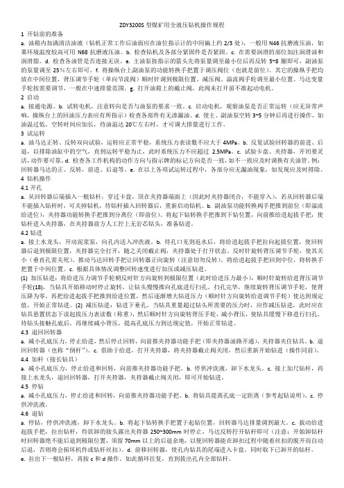
ZDY3200S型煤矿用全液压钻机操作规程1 开钻前的准备a. 油箱内加满清洁油液(钻机正常工作后油面应在油位指示计的中间偏上约2/3处),一般用N46抗磨液压油,如果环境温度较高可用N68抗磨液压油。
b. 检查钻机及各部分紧固件是否紧固。
c. 在需要润滑的部位加注润滑油和润滑脂。
d. 检查各油管是否连接无误。
e. 主油泵按指示的箭头先将泵量调至最小位后再反转5~8圈即可,副油泵的泵量调至25%左右即可。
f. 将操纵台上副油泵的功能转换手把置于调压阀位(也就是前位)。
其它的操纵手把均放在中间位置,背压调节手轮(单向节流阀)顺时针调到极限位置。
减压阀、溢流阀手轮调至最小位置。
马达变量手轮按需要调节,一般在中速排量范围。
g. 打开油箱上的截止阀,此阀未打开前不准起动电机。
2 启动a. 接通电源。
b. 试转电机,注意转向是否与油泵的要求一致。
c. 启动电机,观察油泵是否正常运转(应无异常声响,操纵台上的回油压力表应有所指示)检查各部件有无渗漏油。
d. 使主、副油泵空转3~5分钟后再进行操作,如油温过低,空转时间应加长,待油温达20℃左右时,才可调大排量进行工作。
3 试运转a. 油马达正转、反转双向试验,运转应正常平稳,系统压力表读数不应大于4MPa。
b. 反复试验回转器的前进、后退,以排除油缸中的空气,直到运转平稳为止,此时系统压力不应超过 2.5MPa。
c. 试验卡盘、夹持器,开闭要灵活,动作要可靠。
d. 检查各工作机构的动作方向与指示牌的标记方向是否一致,如不一致应及时调换有关油管。
例:回转器马达的正、反转,前进、后退等。
e. 在以上各项试运转过程中,各部分应无漏油现象,如发现应及时排除。
4 钻机操作4.1开孔a. 从回转器后端插入一根钻杆,穿过卡盘,顶在夹持器端面上(因此时夹持器闭合,不能穿入)。
若从回转器后端不能插入钻杆时,可关掉钻机,待钻杆插入回转器后,重新启动钻机。
b. 副油泵功能转换阀手把推到前位(即溢流给进位),夹持器功能转换手把推到分离位(即前位)。
ZDY3200型煤矿用全液压坑道钻机操作步骤

ZDY3200型煤矿用全液压坑道钻机操作规程一、启动前的检查1、液压胶管及电缆的连接是否正确;2、检查液压油,钻机工作是,油箱中的油液充满油位指示针的以上为好,不允许低于油位指示针的最下部,以防止油泵吸空和温度计不能真实地反映油温;3、打开油箱上的两个截止阀,该阀未打开前不准启动电动机;4、主油泵一般调到最大排量位置左右。
顺时针旋转手轮排量增加,反之减少;5、操作台上的各操作手把处于中间位置,给进调压阀调到压力较小的位置。
二、启动1、验明电动机的旋转方向,如果是倒转的情况请立即停下电动机,切断电源后将电缆的两相连接调换一下。
2、油泵空转5分钟后再进行操作,如果油温过低,应待油温达20℃左右时才能进行工作。
3、使给进装置前进、后退(可用“快进快退”手把)几次,以排除油缸中的残留空气,直到运动平稳无爬行。
4、钻架摆角步骤(以前端上升为例):(1)、给进操作手把放在“起拔”位置,使回转装置移到后端,减少前端的重量。
(2)、拧松前端两个固定机架的固定手把。
(3)、扳动升降手把使钻架“起升”,每次每端上升角度不宜过大(一般为15°~25°),直至到所需位置。
(4)、拧紧固定手把。
调节另一端钻架时,需将回转器移到相反端,用同样的步骤操作,可点动“快进快退”手把,协助动作。
5、开钻(1)、无xx芯开孔a、卡夹手把和联动手把放在“卡盘开,夹持器开”位置,从主轴后端放入钻杆并通过夹持器。
b、卡夹手把和联动手把放在“卡盘开,夹持器闭”位置,夹持器夹紧钻杆,在夹持器前端拧上无岩芯钻头,准备钻进。
(2)、取芯开孔a、拉出夹持器上端两根长螺栓,是夹持器向下翻转,卡盘后退到最后端位置,在卡盘前放入粗径取芯钻具(小于108mm).b、卡夹手把和联动手把放在“卡盘开,夹持器闭”位置,从主轴后端放入钻杆,人工拧入粗径钻具。
c、卡夹手把和联动手把放在“卡盘闭,夹持器开”位置后,进入下述钻进操作。
d、待钻具钻入孔内,钻杆通过夹持器位置时,停钻,将两边夹持器翻上,装上上端两根长螺栓后,继续进入下述钻进操作。
中秀3200安装调试说明(新1版)

第十二章、井道厅门门锁安装说明 1、井道门锁安装图 2、说明
第十三章、对讲装置安装说明 1、井对讲装置安装图
第十四章、井道照明安装说明 1、井道照明安装图
第十五章、ES变频器操作说明 1、编码器说明(ERN1313型编码器) 2、键盘操作说明 3、变频器参数说明 4、主机自调谐说明 5、ES变频器故障表
J8
COM6 COM7 T17 T18 T14 T15 T16 COM8 COM9
J9 A+ AB+ B551
J10 CAN1H CAN1L LADH LADL CARH
J11 CARL GROH GROL 485A 485B
3/85
MF5000系统调试手册
GWH2009.11.1
3、主控制板MF5000的I/O输入输出端口说明
序号 插件代号 功能说明
1
J1——J4 输入端子
2
液晶操作器
3
CPU控制板
4
S1、S2 高速计数信号切换跳线
5
J11
输入端子
6
J10
CAN通讯总线
7
J9
CAN通讯总线
8
J6——J8 输出端子
9
J5
电源输入/输出端子
10
J16
RS232通讯端口
备注 开关量输入
S1、S2断开时使用差分信号 高速计数输入 备用、外呼通讯、内呼通讯端口 并联/群控通讯端口, 继电器——开关量输出 5V、24V各一组独立电源 PC上位机通讯接口
551
主控制板对外提供24V电源-,电流<1A
5、通讯端子说明
插件代号 端口号 功能说明 MONH 备用CAN通讯H MONL 备用CAN通讯L
西安ZDY3200S钻机使用与维修保养

ZDY3200S钻机使用与维修保养一钻前检查和准备1.检查钻机稳固和联接的可靠性a液压单体支柱是否松动钻机在运转过程中产生震动使顶板或地板松动,导致钻机稳固不可靠。
要仔细检查排除事故隐患。
b各紧固螺丝是否松动钻机的螺纹联接部位较多,在钻进中由于震动的原因,会使各连接部位的螺丝松动,要及时紧固,减少震动和噪音以及对紧固件的破坏。
2.检查钻机、钻具的完整性a钻机零部件是否有缺损b油箱内液压油的油位,正常油位不少于油位指示计偏上2/3。
3.检查油管连接的正确性按照《ZDY3200S钻机使用说明书》中第6.2章节《管路连接》规定的连接方法检查油管连接是否有误。
4.开机试运转a听钻机有无异常噪音产生钻机的原因:I 油液面过低,主副泵吸油漏斗产生吸空状态,大量空气进入高速旋转的主副泵而产生的噪音,同时伴有动力机组振颤、给进与回转无力现象。
发生上述情况时,应及时给油箱补充液压油,在井下补充液压油时,要注意污物进入油箱。
II 油箱与主副泵连接部位有截止阀连接,若出现截止阀连接密封不严时,有空气通过连接密封不严部位进入油箱,使油箱内产生大量的空气气泡,并随主副泵吸入柱塞与柱塞套空间,产生气蚀性震动噪音。
出现这种情况应及时解决密封不严问题,消除噪音。
III钻机的连接部位较多,在钻进中由于震动的原因,会使各连接部位的螺丝产生松动和噪音。
IV轴承或齿轮损坏,高速转动时产生噪音。
b看钻机各接头有无渗漏油发现有漏油现象应及时紧固漏油处的接头或更换密封件。
二正常钻进的操作方法按照《ZDY3200S钻机使用说明书》中第8.5—8.11章节所介绍的方法操作。
三日常保养1. 应尽量使用液压油,如果没有液压油而以相同粘度的机械油作代用品时,元件使用寿命将受影响。
2. 初次加油时,应认真清洗油箱,所加液压油必须用滤油机过滤。
3. 在井下不许随便打开油箱盖和拆卸液压元件,以免混入脏物。
4. 使用中经常检查油面高低,发现油量不足即应通过空气滤清器加油。
操作规程(瓦斯抽采钻孔)
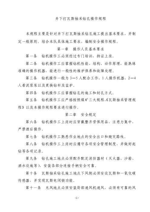
井下打瓦斯抽采钻孔操作规程本规程主要是针对井下打瓦斯抽采钻孔施工提出基本要求,并制定一般原则。
结合本队具体施工要求,编制安全操作规程。
第一章操作人员基本要求第一条钻机操作工必须经过专门培训,持证上岗。
第二条钻机操作工应掌握钻机性能、结构、动作原理,能熟练准确的操作机器,能进行一般性的维护保养和故障处理。
第三条钻机操作一般为3—5人配合工作,1人操作机器,2—4人看泥浆泵以及更换钻杆及监护。
第四条钻机操作工应掌握钻孔的施工和封孔方式。
第五条钻机操作工应严格按照煤矿三大规程、《瓦斯抽采管理规程》以及本操作规程要求进行操作。
第二章安全规定第六条钻机操作工上岗时应穿戴整齐劳保用品,注意力集中,严禁酒后操作。
第七条钻机操作工熟悉作业地点的安全出口和避灾路线。
第八条钻机操作工上岗时应遵守各项安全管理制度,并做好起钻等各项记录。
第九条钻孔施工地点必须配齐配足消防器材(灭火器、沙箱、洒水设施等),安装各部分连接手柄安全可靠。
第十条瓦斯抽采钻孔施工地点下风侧必须安设瓦斯和一氧化碳传感器,并实现瓦斯电闭锁功能。
第十一条无风地点必须安装局部通风机通风,必须有可靠的风电闭锁装臵。
第十二条钻机前后10m范围内设臵警戒,严禁无关人员进入钻机移动范围内。
第十三条钻机停送电操作要求(一)停送电作业时必须由专业操作人员进行操作,并严格执行电气设备停送电相关规定。
(二)钻机操作工停电时(未进行搬家的零时停电),先将夹持器收紧,夹紧钻杆,再将所有手把调整到零位,最后将钻机供电开关的手柄扳至分闸位臵并闭锁。
(三)钻机操作工送电时,先检查钻机附近20m范围内的瓦斯情况,确认瓦斯浓度为0.5%以下,且钻机手把都在零位及钻机附近无人员时,方可送电。
第三章设备的安装、拆卸与搬运一、钻场的安全设施和条件:第十四条确定孔位。
应由钻孔施工设计人员及有关部门进行现场查勘,孔位一但确定,不得擅自改动。
第十五条钻场场地平整、宽畅,机械安装必须牢固、安全、可靠,立柱安装必须不少于三个固定点。
ZDY3200S型煤矿用全液压坑道钻机

ZDY3200S型煤矿用全液压坑道钻机使用说明书(安装、使用本产品时请详细阅读本说明书)煤炭科学研究总院西安分院二00五年三月前言ZDY3200S(MKD-5S)型钻机是一种低转速、大扭矩、能够钻进大口径孔的全液压坑道钻机。
该钻机为煤矿井下钻进大口径瓦斯抽放孔及其它工程孔提供了必要的钻探设备。
该机具有结构合理,技术性能先进、工艺适应性强、操作省力、安全可靠、解体性好、搬迁方便等优点。
采用全液压传动,对于使用和维修提出了更高的要求,为了使机器的优点得到充分发挥,本说明书对钻机的结构,传动原理、使用与维修方法均作了较详细的介绍。
希望用户在使用钻机以前认真阅读并严格按有关规定执行。
并对使用过程中出现的问题及建议及时反馈给我们,以便改进我们的工作,更好的为用户服务。
本产品执行Q/MKYX 16213—2005标准。
━━━━━━━━━━━━━━━━━━━━━━━━━━━━━━━━━━━安全警示说明:煤矿井下使用时,必须选用YBK2-225S-4矿用隔爆型三相异步电动机;隔爆型三相异步电机;隔爆型三相异步电动机、液压支架胶管总成应有安全标志。
钻机出厂之前,系统工作压力已调定。
用户在使用过程中,系统压力不得超调。
否则,出现任何责任目录1.适用范围错误!未定义书签。
2.型号含义错误!未定义书签。
3.主要技术参数错误!未定义书签。
4.钻机结构简介错误!未定义书签。
5.液压系统工作原理错误!未定义书签。
6.钻机的稳装及管路连接错误!未定义书签。
7.安全警示错误!未定义书签。
8.操作方法错误!未定义书签。
9.维护保养错误!未定义书签。
10.故障的判断与排除错误!未定义书签。
11.产品的成套性错误!未定义书签。
12.易损件明细表错误!未定义书签。
1.适用范围ZDY3200S型钻机是动力头式全液压钻机,转速范围宽、扭矩大,能满足煤矿井下钻进各种用途的钻孔,如抽放瓦斯孔、注水孔及其它工程用孔,也可用于地表工程施工。
主要用于大口径牙轮钻进,也适用于大口径硬质合金钻进和冲击回转钻进。
ZDY3200S型煤矿用全液压钻机操作规程.pdf

ZDY3200S型煤矿用全液压钻机操作规程1 开钻前的准备a. 油箱内加满清洁油液(钻机正常工作后油面应在油位指示计的中间偏上约2/3处),一般用N46抗磨液压油,如果环境温度较高可用N68抗磨液压油。
b. 检查钻机及各部分紧固件是否紧固。
c. 在需要润滑的部位加注润滑油和润滑脂。
d. 检查各油管是否连接无误。
e. 主油泵按指示的箭头先将泵量调至最小位后再反转5~8圈即可,副油泵的泵量调至25%左右即可。
f. 将操纵台上副油泵的功能转换手把置于调压阀位(也就是前位)。
其它的操纵手把均放在中间位置,背压调节手轮(单向节流阀)顺时针调到极限位置。
减压阀、溢流阀手轮调至最小位置。
马达变量手轮按需要调节,一般在中速排量范围。
g. 打开油箱上的截止阀,此阀未打开前不准起动电机。
2 启动a. 接通电源。
b. 试转电机,注意转向是否与油泵的要求一致。
c. 启动电机,观察油泵是否正常运转(应无异常声响,操纵台上的回油压力表应有所指示)检查各部件有无渗漏油。
d. 使主、副油泵空转3~5分钟后再进行操作,如油温过低,空转时间应加长,待油温达20℃左右时,才可调大排量进行工作。
3 试运转a. 油马达正转、反转双向试验,运转应正常平稳,系统压力表读数不应大于4MPa。
b. 反复试验回转器的前进、后退,以排除油缸中的空气,直到运转平稳为止,此时系统压力不应超过 2.5MPa。
c. 试验卡盘、夹持器,开闭要灵活,动作要可靠。
d. 检查各工作机构的动作方向与指示牌的标记方向是否一致,如不一致应及时调换有关油管。
例:回转器马达的正、反转,前进、后退等。
e. 在以上各项试运转过程中,各部分应无漏油现象,如发现应及时排除。
4 钻机操作4.1开孔a. 从回转器后端插入一根钻杆,穿过卡盘,顶在夹持器端面上(因此时夹持器闭合,不能穿入)。
若从回转器后端不能插入钻杆时,可关掉钻机,待钻杆插入回转器后,重新启动钻机。
b. 副油泵功能转换阀手把推到前位(即溢流给进位),夹持器功能转换手把推到分离位(即前位)。
Sandvik DD320S开发钻机的技术规格和主要特点说明书
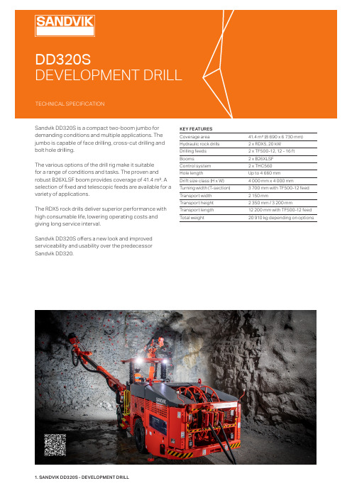
KEY FEATURES Coverage area 41.4 m² (8 690 x 6 730 mm)Hydraulic rock drills 2 x RDX5, 20 kW Drilling feeds 2 x TF500-12, 12 - 16 ft Booms 2 x B26XLSF Control system 2 x THC560Hole lengthUp to 4 660 mm Drift size class (H x W) 4 000 mm x 4 000 mm Turning width (T-section) 3 700 mm with TF500-12 feed Transport width 2 150 mmTransport height 2 350 mm / 3 200 mmTransport length 12 200 mm with TF500-12 feed Total weight20 910 kg depending on optionsSandvik DD320S is a compact two-boom jumbo for demanding conditions and multiple applications. The jumbo is capable of face drilling, cross-cut drilling and bolt hole drilling.The various options of the drill rig make it suitable for a range of conditions and tasks. The proven and robust B26XLSF boom provides coverage of 41.4 m². A selection of fixed and telescopic feeds are available for a variety of applications.The RDX5 rock drills deliver superior performance with high consumable life, lowering operating costs and giving long service interval.Sandvik DD320S offers a new look and improved serviceability and usability over the predecessor Sandvik DD320.HYDRAULIC SYSTEM Powerpack2 x HPP555 (55 kW)Filtration (pressure / return)20 µ / 10 µOil tank volume 270 liters (drilling)Oil tank filling pump ManualCooler for hydraulic oilOW30 oil-to-water (2 x 30 kW)AIR AND WATER SYSTEM Flushing of holes By water Water booster pump WBP-1010Water pump capacity 150 l/min Water pump inlet pressure 2 bar (Min.)Flushing water pressure 10 - 15 bar Shank lubrication device SLU2 (air / oil mist) Air compressorCTN9, 1 m³/min (7 bar)Rock drill oil consumption 180 - 250 g/h Rock dril air consumption 250 - 350 l/minELECTRIC SYSTEM Standard voltage 380 - 690 V (± 10%)Total installed power 135 kW Main switch gear MSE 20IP classification Specification TS2-132Starting method Star delta 380 V - 690 V Direct online 575 VAutomatic cable reel TCR3E with spooling system Cable reel control Operator station only Batteries2 x 12 V, 145 AhFront and rear lights(combined working and driving)8 x 50 W LED (4 200 lm, 6 000 K)Parking rear brake / park lights2 x Red LEDDRILLING FEED Type of feed TF500-12’ Standard TF500-14’ Optional TF500-16’ Optional Feed force Max. 25 kN Max. 25 kN Max. 25 kN Total length 5 270 mm 5 880 mm 6 490 mm Hole length 3 440 mm 4 050 mm 4 660 mm Rod length 3 700 mm 4 305 mm 4 915 mm Net weight 500 kg530 kg560 kgOPERATOR’S SAFETY CANOPY Canopy certification FOPS (ISO 3449)Unit height in tramming 3 200 mmOperation Standing drilling, seated tramming Operator’s seatSeat with safety belt Sound pressure level EN 16228Operator station: 100 dB(A)HYDRAULIC ROCK DRILL Type of rock drill RDX5 (TS2-433)Percussion power 20 kW Percussion pressure Max. 220 bar Percussion rate 67 HzRotation speed Max. 250 rpm (with OMS80)Rotation torque 400 Nm (with OMS80)Hole size (drifting)43 - 64 mm Hole size (cut hole)76 - 127 mmRecommended rod T38 - Hex 35 - R32T38 - Hex 35 - Alpha 330T38 - Hex 35 -R35Shank adapter (male)T38Weight 210 kg Length 955 mm Profile height 87 mmBOOM Type of boom B26XLSF (TS2-260)Face drilling coverage 41.4 m² (parallel holes)Parallelism Automatic hydraulic Boom extension 1 700 mm Feed extension1 600 mm Boom weight (without hoses) 1 960 kg Feed rotation angle (roll-over)360ºDRILLING CONTROL SYSTEM Type of control system THC560 (TS2-361)Operating principle Hydraulic control Manual boom controlDirect control Fully proportional Hydraulic parallelism Drilling controlManual collaringFeed / percussion control Anti-jamming system Flushing controlAutomatic cycleStop and return automaticsCARRIERType of carrier NC7S (frame-steered)Carrier articulation± 40°Rear axle oscillation± 10°Ground clearance320 mmDiesel engine Cummins QSB 4.5, 124 kW Stage IIIA Exhaust catalyzer StandardTransmission HydrostaticAxles SpicerTires12.00-20Service brakes SAHR type, fail save wet disc brakes Parking andemergency brakesSAHR type, fail save wet disc brakesTramming speed 12,5 km/h (Horizontal) 6,5 km/h (14%=1:7=8°)Gradeability / sideways tilt Max. 15° / 5° (according to EN 16228-2)Rod rack on carrier side For 10 - 16 ft rods and two shank adaptersFuel tank140 litersCarrier stabilization 2 x Vertical (front) 2 x Vertical (rear)Hand held fire extinguisher 1 x 9 kg (type ABC)Tramming alarm Standard Knowledge Box™Connectivity solution (TS2-535) Colour scheme SandvikDocumentation 1 x Operator’s manual1 x Maintenance manual1 x T echnical manual (in English only)1 x Parts manual (in English only)2 x T oolman USB keyOPTIONAL FEATURES AND PACKAGESBoom*Type of boom B26XLS-NV instead of B26XLSFDrilling feed*Feed length*Telescopic feed14’, 16’TFX6/12, TFX8/14Hydraulic system*Oil tank filling pump ManualDrilling control systemBoom movement isolation switchAccess detectorAt each sideMandatory in Europe (TS2-211)Electric system*Electric cableGround fault and overcurrentprotectionAuxiliary outletExtra working lightAmber flashing lightSpecification TS2-121VYK (excluding Canada / USA)1 x 110 V or 1 x 230 V, 16 A2 x 50 W LED (4 200 lm, 6 000 K)LED (24 V)Air and water systemFlushing flow control*Manual end of hole air flushingWater hose reel with water hose2 boomsIncluding CT28 air compressorTHR2.5E with 38 mm (1 ½”), 65 mCleaning systemHP system with reel Up to 180 bar (TS2-343)Greasing systemsCentralized greasing pointsManual systemSpecification TS2-463Greasing unit with pump, reel andnozzle (TS2-463)Operator’s safety cabin / canopy*Safety cabinRotating seatFOPS / ROPS (ISO 3449 / 3471)For drilling and trammingFire suppression systemManual or automatic systemAuto. fire suppression systemAnsul, 6 nozzles (TS2-460)Sandvik Eclipse™ (TS2-461)Carrier*Diesel engine*Foam filled tiresWheel chocks and holdersRod rack and shank holderB4.5, 129 kW, Tier 4F, Stage V4 pcs2 SetsOn carrier sideExtra itemsBerg plug and socketSpare rock drillSpare wheel assemblySpecial tools for rock drillWarranty extensionDocumentation*Package: Country specificoptions*Package: Harsh water250 ARDX5Air or foam filled tireField tool set (TS2-434)Complete tool set (TS2-435)One year (excl. Kazakhstan)Extra paper, CATbase, Link onemanualsLAM, CIS, TUR, US/CAN, SASpackageBasic or advanced (TS2-049)*) Replaces standard featureOverall length TF512TF514TF516TFX6/12TFX8/14*B26F mm 12 10012 30012 70011 70011 700B26XLSF mm 12 65012 85013 30012 30012 300*B26XLS-NVmm13 30013 50013 95012 90012 900*) Optional boomCOVERAGES Type of boom A B C D *B26F mm 5 980 5 280 6 7107 690B26XLSFmm6 730 6 0307 7308 690*B26XLS-NV mm6 7306 0308 0009 350*) Optional boomT S 2-394:07/E N G /M E T R I C © S a n d v i k M i n i n g a n d R o c k S o l u t i o n s 2022 S A N D V I K i s a r e g i s t e r e d t r a d e m a r k o w n e d b y S a n d v i k I n t e l l e c t u a l P r o p e r t y A B i n S w e d e n a n d o t h e r c o u n t r i e s .Sandvik Mining and Rock Solutions reserves the right to make changes to the information on this data sheet without prior notification to users. Please contact a Sandvik representative for clarification on specifications and options.ROCKTECHNOLOGY.SANDVIK。
3200钻机说明书
ZDY3200S型煤矿用全液压坑道钻机使用说明书(安装、使用本产品时请详细阅读本说明书)煤炭科学研究总院西安分院二00五年三月前言ZDY3200S(MKD-5S)型钻机是一种低转速、大扭矩、能够钻进大口径孔的全液压坑道钻机。
该钻机为煤矿井下钻进大口径瓦斯抽放孔及其它工程孔提供了必要的钻探设备。
该机具有结构合理,技术性能先进、工艺适应性强、操作省力、安全可靠、解体性好、搬迁方便等优点。
采用全液压传动,对于使用和维修提出了更高的要求,为了使机器的优点得到充分发挥,本说明书对钻机的结构,传动原理、使用与维修方法均作了较详细的介绍。
希望用户在使用钻机以前认真阅读并严格按有关规定执行。
并对使用过程中出现的问题及建议及时反馈给我们,以便改进我们的工作,更好的为用户服务。
本产品执行Q/MKYX 16213—2005标准。
━━━━━━━━━━━━━━━━━━━━━━━━━━━━━━━━━━━安全警示说明:煤矿井下使用时,必须选用YBK2-225S-4矿用隔爆型三相异步电动机;隔爆型三相异步电机;隔爆型三相异步电动机、液压支架胶管总成应有安全标志。
钻机出厂之前,系统工作压力已调定。
用户在使用过程中,系统压力不得超调。
否则,出现任何责任目录1. 适用范围................................. 错误!未定义书签。
2. 型号含义................................. 错误!未定义书签。
3. 主要技术参数............................. 错误!未定义书签。
4. 钻机结构简介............................. 错误!未定义书签。
5. 液压系统工作原理......................... 错误!未定义书签。
6. 钻机的稳装及管路连接..................... 错误!未定义书签。
7. 安全警示................................. 错误!未定义书签。
3200钻机说明书

1.电动机 2.主变量泵 3.29.吸油滤油器 4.30.35.截止阀 5.回油滤油器 6.冷却器 7.主油泵系统压 力表 8.多路换向阀 9.副油泵系统压力表 10.单向阀组 11.油马达 12.液压卡盘 13.精滤油器 14. 夹持器 15.给进起拔油缸 16.18.36单向节流阀 17.起拔压力表 19.给进压力表 20.夹持器功能转 换阀 21.起下钻功能转换阀 22.空气滤清器 23.支撑油缸 24.液压锁 25.回油压力表 26.油箱 27. 卡盘回油阀 28.副油泵功能转换阀 31.副变量泵 32.安全溢流阀 33.调压溢流阀 34.单向减压阀
夹持器采用碟形弹簧夹紧,油压松开的常闭式结构。固定在给进装
置机身的前端,用于夹持孔内钻具,还可配合回转器实现机械拧卸钻 杆。夹持器卡瓦座落在卡瓦座上, 靠上下两根销杆限制卡瓦的退出。圆 周方向靠卡瓦座上的一对平键固定。将两根销杆抽出,卡瓦就可以取 出,夹持器通孔即可通过108mm的粗径钻具。 4.1.3 给进装置
西安ZDY-3200S型钻机操作规程

西安ZDY 3200S型钻机操作规程一、开起钻程序1、检查打钻地点前后10米范围内的巷道支护,发现隐患及时处理,保证施工地点的安全;2、检查开关、电缆、钻机的完好情况,杜绝电器失爆,对供风、供水和打钻安全装备(两台灭火器、一箱沙子、一箱黄土、除尘装置等)进行全面检查,不具备打钻条件的严禁开钻;3、将馈电开关或起动开关的手把打到零位,把钻机移到钻孔设计的位置,调整好钻孔角度,按下垫上压前撑后顶的原则将钻机固牢,并将顶杠进行联锁;4、挂好电缆,将开关上架,各打钻安全装置移到位,班组长明确分工后准备开钻;5、钻机空转1-2分钟,发现问题及时处理;6、上紧钻杆和送风器,先送风(水),到孔内出尘或出水为止,在上钻杆人员离开钻杆0;5米以上后才允许送电,打开夹持器(回转器),油缸后撤到位后夹紧钻杆;7、将旋转手把打到正转位置,然后将前进后退手把打到前进位置,进行正常钻进,直到钻孔打到设计要求;8、在打钻过程中发现异常情况及时停钻,找出原因处理完毕后才可继续打钻;9、起钻,将所起的钻杆卸开后码放在钻杆架上,不得乱扔乱放;10、停电、停风(水),并对打钻上风侧10米,下风侧40米范围的文明生产进行处理;11、对电器进行全面检查,并将馈电开关的手把打到零位;12、认真填写打钻原始记录,升井后及时向防突调度进行汇报;13、钻机操作处,风、水管必须安截止阀。
14、施工煤孔时必须配备铜锹、铜锺。
二、钻前检查:1、检查油箱的油是否足够,加油到油标的上标线。
2、检查胶管是否连接正确。
3、接通电源,检查钻机旋转方向是否正确(在起动开关离主机远的地方最好在操作台处安装远方操作,以便操作人员方便开、停机)。
4、检查各油路压力是否正常。
5、检查各操作手柄是否正常。
6、检查机架锚固牢靠,立柱上端要垫枕木。
7、检查冷却器通水量要足够。
三、钻孔操作:1、打钻时,各工作人员必须衣服穿戴整齐,认真操作2、根据需要安装前置水辨或后置水辨,应配置专用的水辨供(风)水阀门。
3200使用说明书

(1) Function mode: Displays the currently selected display (Spectrum, Bar graph, and Counter)(see page 23)(2) Scan mode: Displays the selected scan mode.3 types of scanning may be selected. See page 14 and 26 for manual scan, pages 17& 26 for search and pages 16 & 26 for channel scan.(3) Title name: The data memory, which is, selected (page 37)(4) Marker Frequency: The frequency in which the unit is currently tuned to as indicated by the marker indicator.(5) Ref.Level: The base line reference amplitude(0 level). The Reception modes (page 50)or the selected external Attenuator value (page 46)sets this value.(6) Marker Level: The amplitude value of the signal level the unit is currently tuned to as indicated by the marker.(10) Reception Mode: The type of modulation needed for aural reception of the incoming signal.Note: a CW or a signal other than a Narrow Band FM(NBFM),wideband FM(WBFM), AM or SSB may be displayed by selecting a reception mode which has the appropriate bandwidth(see page 5).button.(11) Sweep Mode: Determines how the scan moves across the screen when the squelch is activated.(See page 26)(12) Displays the value of the squelch level (see page 51).(13) Marker: Indicates the signal level currently being scanned(14) Attenuator Value: Displays the amount of external attenuation connected to the input. Whenan external Attenuator is used, the value of the Attenuator must be added to the Reference level. This is accomplished through the ATT dB set in the systemCONTENTSQuick Main Menu set up guide (ⅰ)Quick System Menu set up guide (ⅱ)Function Key Menu guide (ⅲ)Display Description (ⅳ)Ⅰ. Introduction (4)1. General (4)2. Features (4)Ⅱ. Specifications (4)Ⅲ. Precautions (7)Ⅳ. Functional Description (9)1. Panel Description (9)Ⅴ. Basic operation (12)1. General (12)1 Prior to connecting to a power source (12)2 Input connection (12)3 Powering the unit on (12)4 Entering a Frequency value (13)5 Scanning (13)6 Positioning the Frequency marker (14)7 Power Off (14)2. Manual Scan (14)3. Ch. Memory Scan (16)4. Search Scan5. Difference Mode6. Frequency Counter7. Recorder Mode8. Power supply1 Car and AC adapter2 Battery Replacement Ⅵ. Menu Description1. The Main Menu1 Main menu display2 Function Modes3 Scan Modes4 Sweep Mode5 Edit Channel 5-1 Selecting Edit Channel 5-2 Assigning a Channel number 5-3 Entering a Channel name5-4 Insert Function5-5 Delete Function1-6 Setup Memory6-1 Setup Memory6-2 Save and Load setups 6-3 Title Names1-7 Data Memory 7-1 Data Memory Setup 7-2 Saving and Loading7-3 Title name ....................................................................................17..............................................................................19...........................................................................19.................................................................................21....................................................................................22........................................................................22........................................................................22....................................................................................23.................................................................................23...........................................................................23..............................................................................23....................................................................................26....................................................................................27 (28) (28) (30)............................................................30...........................................................................32...........................................................................32.................................................................................32..............................................................................32.....................................................................34....................................................................................35 (37) (37)........................................................................38 (38)8 SSB BFO9 Hold Mode10 Level Hold 2. The System Menu1 System Menu display2 db Unit3 Power Off4 I/O Menu5 Printer Menu6 Copy Set Mode7 External Attenuators 8 Test Set Menu9 SCRB Menu10 Battery Check 11 Keyboard Buzzer 3. Function Keys …………1 RUN2 STEP3 MODE4 SQL (Squelch Level)4. LCD Men …………u 1 LCD Contrast2 LIGHT 3 GRID 4 PRINT ........................................................................................................ 39..........................................................................................39.. (41)....................................................................................42...........................................................................42............................................................................................... 43........................................................................................... 43............................................................................................ 44........................................................................................ 44....................................................................................45...........................................................................46.................................................................................47....................................................................................47.................................................................................. 48 (48)................................................................................ 49.............................................................................................. 49................................................................................................49. (50)............................................................................ 51.......................................................................................51.................................................................................51................................................................................................52...................................................................................................52 (53)I. INTRODUCTION1. GeneralThe 3201 is the world’s first hand-held RF Field Strength Analyzer.With a wide band reception range of 100 KHz to 2060MHz, the 3201is a compact and Lightweight portable analyzer. It is the ideal tool for field RF technicians to test, install and Maintain Mobile Telecommunications Systems, Cellular and Cordless Phones, CB Radios, Paging Systems, Cable and Satellite TV systems as well as antenna site measurements and Maintenance.2. Features•100KHz to 2060MHz measurement range•Measures and demodulates Narrow Band FM(N-FM), Wide Banc FM(W-FM),AM, Single Side Band (SSB) signals.•Built-in 2GHz Frequency Counter.•PLL tuning system for precise frequency tuning.•Up to 160 channels may be scanned and displayed on the LCD•Built-in Speaker•192 X 192 pixel backlit LCD•All functions are menu selectable•Has a RS-232 and parallel interfaceII. SPECIFICATIONSReception FrequencyFrequency range Freq. Accuracy (TXO) Freq. Accuracy (display) DemodulationStep frequencyData memorySet Up memory Reception sensitivityScan spee : 100KHz to 2060MHz: ±3PPM: ±25PPM: N-FM, W-FM, AM, SSB: 5KHz to 9995KHz in multiples of 5KHz and 6.25KHz: Stores 10 displays of up to 160 Channels per display(1600) : Stores 10 setups for each scan mode: Approx.0 –6 dBµEMF.(S/N: 12dB at N-FM, 10dB at W-FM): 12.5Ch./sec.max.dInput impedanceMax.Input voltageAudio output Level MeasurementN-FM mode RangeResolutionAccuracyRepeatabilityBandwidthW-FM/AM/SSB RangeResolutionAccuracyRepeatabilityBandwidth Spurious and Noise Level internally generated : 50Ω(standard): Max. 5V RMS : 120mW into 8Ωspeaker: -70 to –20dBmV(-10 to 40dB µV)for 300 to 1800MHz -60 to –20dBmV(0 to 40dB µV)for 1 to 300MHz and 1800 to 2000MHz : ±0.5dB µV : ±3dB(at an ambient of temperature of 23℃±3℃): ±2dB : Approx. 12.5KHz(-6dB): -60 to –10dBmV(0 to 50dB µV)for 300 to 1800MHz -50 to –10dBmV(10 to 50dB µV)for 10 to 300MHz and 1800 to 2000MHz : ±0.5dB µV : ±3dB(at an ambient of temperature of 23℃±3℃): ±2dB : WFM: Approx. 180KHz(-6dB), AM/SSB:Approx.2.4KHz(-6dB): -35dBc W-FM: -45dBc for N-FM typical, below a full scale signal level frequency.FunctionsDisplay modes Sweep modesScan modesHold modesLevel hold modesSquelch function Copy function : Spectrum displayMulti Bar graph display(5, 10, 20, 40, 80, 160CH)Single Bar graph displayDifference frequency displayFrequency measurement level display: Single, Normal, Free Run, Free Single : Manual, CH.Memory and Search scan : Delay run, Delay hold and delay stop : Max. Hold, Hold, 40mS, 100mS and 200ms peak hold : Squelch level is displayed as a bar graph and a digital Readout. Thesquelch level may be adjusted to any value from the reference level to Full scale: The copy set mode allows the contents of the Channel edit, Setup andData memories to be copied to an external device. Data may also be written in to these memories from an external device.Frequency CounterFrequency range No. of digits Resolution Accuracy Sampling time Input sensitivityInput impedance Max.Input voltage Data memory : 9MHz to 2060MHz: 7 digits: 1KHz:±50 PPM ±1 count: 0.512sec.: 9MHz to 2000MHz: 150mV RMS 20MHz to 1000MHz: 100mV RMS : 50Ω: 5V RMS Max.: 10 readings may be storedMiscellaeous SpecificationsLCDBack lightRS-232C Interface Power sourceAuto Power Off : 192 X 192 pixels green, Led backlit: Back light will shut off 5 seconds after the last key depression or continuously on may be selected: 1200, 2400, 4800, 9600 BPS(8 Pin Mini Din): (6)1.5V AA type NICD batteries 11V to 16V 400mA Max.AC to DC adapter, 12VDC car adapter: Unit will shut off after 5, 10, 20 or 30 minutes of idle time,menu selectable.Physical specificationsOperating Temperature & Humidity Storage TemperatureDimensionWeight : 0℃to 40℃at 35-85% RH: 10℃to 50℃: 4”(W) x 9”(H) x 1.77”(D): Approx. 1.4Ib(including antenna)Std AccessoriesCoaxial cable, earphones, Antenna (receiver only), (6)AA NiCd batteries RS232C cable, carrying Case carrying strap, Vehicle power adapter, AC/DC adapter, operators manualOptional accessories: Parallel printer cable and PR-232C mini printerIII. PRECAUTIONSStorageDo not store this equipment in:•Direct sunshine, near heating devices or in an automobile in the summer time.•Locations with high humidity and poor ventilation.•Dusty or smoky environments.•Extremely low temperature.Handling•This product is a sophisticated electronic device, do not:Service or perform adjustments.•Do not apply great force to the keys and switches.Be sure the slide switch inside the battery cover is set to the right Position, If alkaline batteries are used set the switch to right (dry position). If NiCd batteries are being used set the switch to the left (NiCd position)Warning: If the switch is in the NiCd position when alkaline batteries are used may cause these batteries to over heat, explore or leak.AntennaDue to the broad applications of this unit, the supplied antenna is for the 800MHz cellular band. It may be necessary to use a different antenna more appropriate for your application.The receiving conditions vary with location and antenna. On some occasions, it’s not possible to receive the desired signals due to strong Interference from other electronic sources such as broadcast stations.Connecting to other devicesWhen connecting this unit to other devices (CATV cable etc) be sure that the measured system voltage is not greater than the maximum input voltage. Use attenuators to preventthe input voltage from being overloaded by higher than the rated input voltage(5V rms).If the input voltage is greater than the rated input voltage of this unit, possible damage may result.Be sure that the external DC input jack is the correct polarity.The DC jack tip must be positive in respect to ground.If the unit is not functioning correctly or “locked up”when the power is turned on perform the following procedure:•Press the power button to shut the power off•keys simultaneously. This will clear the internal memory and return the unit to normal operation.Note: An alternate method to clear a malfunctioning unit is to select ALL RESET from Test set menu located in the system menu.IV. FUNCTIONAL DESCRIPTION 1. PANEL DESCRIPTION1). Signal level input connectorConnect to the Antenna or Coax cable. Maximum input Voltage is 5 Volts.2).Frequency counter inputConnect to the signal source to be measured. Maximum input voltage is 5 Volts.3). Volume controlAudio output Volume control. To increase the volume, rotate the Volume control clockwise.4). Earphone Jack5). Attenuator ““(Pushed in) Inserts 10dB of attenuation into the Signal level input. Used in the presence of noise or very strong signals.““(Pushed Out) No attenuation6). LCD (Liquid Crystal Display)Displays the Signal levels, their characteristics (frequency, amplitude, etc) and pertinent system data.7).Press this button to turn the power on. Press again to turn the power off.LCD menu items consists of LCD Contrast control, LCD Grid select, Backlight and Print command. These items arekeys.9).key a 3rd time returns the LCD to the signal level displays.10).This key enters the menu item you have selected or the numeric values you have enteredform the keyboard.These keys select: Run, Step frequency menu, Reception modemenu, and squelch Level.These keys are located at the bottom of the LCD display. They also are used to select the itemskey will enter a negative13). This key is used for entering decimal points. If a decimal point is already entered, this key isthen used for clearing a keyboard entry.14).This key is used for incrementing and decrementing the Market frequency and for selecting items in the various menus.15).Rotary Dial Knob) but at a faster rate.The rotary dial knob allows one-handed operation.16). DC Input Jack The AC/DC adapter and cigarette lighter adapter connect to this input for applying DCPower to the unit from an external source.17). RS-232C Connector(8 pin mini DIN connector)This connector is used for interfacing to a personal computer or a printer.18). Belt ClipFor attaching the RF-3201 to your belt.19). SpeakerFor listening to the demodulated output of a RF carrier signal level.V. BASIC OPERATION1. General1 Prior connecting to a power sourceSee page 22 for inserting batteries, battery charging and connecting to a power source.2 Input connectionConnect the antenna or coax cable to the BNC input marked ANT if measuring a RF carrier signal level. If measuring a frequency connect the coax cable to the Frequency counter input.Note: Do not exceed 5V rms3 Powering the unit on[2] The welcome screen will be displayed followed by the last screen that was displayed prior toshutting the power off.[4] See the graphic below for a description of the LCD display when powered on.[5] Adjust the volume control for an appropriate sound level. If the signal level is belowthe squelch level there will be no output sound from thespeaker.key to quit.4 To enter a frequency value[1] The selected scan mode is displayed in the top center of the LCD. In the above,example manual scan was selected. The frequency entered from the keyboard in thiscase is the is the center frequency and is the frequency indicated by the market.Note: in order to enter a frequency from the keyboard scanning must be halted.Example1: To enter 100.00625MHz from the keyboard: Press the following key sequence:Example2: To enter 500KHz press the following key sequence:Note:but if the decimal point has[3] The frequency value has different functions for the Manual, Search and Cannel scan.The entered frequency in manual scan sets the Center frequency where as the entered frequency values in search scanning sets the Start and stop frequencies.In the Channel scan mode the entered frequency value is stored along with its channel name in the Channel memory (see page 28 through 30). This will be used for scanningpreviously stored scans along with their channel namesand frequency.5 Scanningicon and the scanning will start.[2] If Free Run sweep is selected from the Sweep menu scanning will be continuous andkey a second time will stop the scanning.[3] When Normal Sweep has been selected the scan will halt when the signal level value isgreater than the squelch level. Scanning will resume when the signal level value dropsbelow the squelch level.[4] When scanning is halted the marker will indicate the signal level and display theamplitude value on the LCD.6 Positioning the Frequency Marker indicatorwhen the scanning has been halted can be used to position the marker frequency indicator over asignal level in order to find it’s frequency andsignal level amplitude values.7 Power Offfinished.Note: When the unit is powered-on again, the screen prior to powering off will be displayed.2. Manual Scan Mode[1] when Manual scan mode is selected, It is necessary to enter the following information:a) The Center frequency value from the keyboard,menu.c) The Frequency Span which is set by the Step frequency. The Frequency span isdetermined by the number of channels per displayed (Selected from the function menumultiplied by the step frequency. See the 2 examples below on how the frequency spanis determined by the step frequency.Example 1: To set a frequency span of 8MHz using the Spectrum display mode a stepfrequency of 50KHz is required(160 x 0.050MHz = 8MHz).Example 2: If a 40 Bar graph display is selected and the step frequency is 100KHz theFrequency span is 40 x 0.1MHz = 4MHz.[2] To select the Manual scanning mode press the following key sequence:(Select the Scan menu) (Select Manual Scan mode)[3] The center frequency, Span, Step Frequency and reception mode are displayed in the lowerpart of the LCD.Note:The frequency span is not displayed in the 2 channel difference, Single or counter modes.[4] To enter the Center/Market frequency the unit must not be Scanning (Run icon not highlighted)(See pages 12 and 13)[5] When the scanning is stopped the Market frequency indicator may be positioned over akeys or rotating the dial knob.The position of the market may be moved by up to 160 channels.(+80 channels to –80 channels)In the 2-channel mode the market/center frequency and the difference frequency are scanned and displayed.Note:Scanning is not available in the signal channel or counter mode.[7] You can save 10 displays of up to 160 channels and their setups by storing them in the Dataand setup memory. These may be selected from the main menu.(see pages 32 through 38)[8] Example of a manual scan display3. Ch. Memory Scan[1] Names and frequencies of signal levels of interest may be entered and stored in thechannel memory prior to scanning. When scanned these signal levels will be displayedalong with their frequencies and name.Ten displays of up to 160 signal level Channels per display(1600 channels total) may beentered, edited and stored in the channel memory (See pages 28 through 30)[2] To select the Channel scan mode press the following key sequence.(Select Scan Mode) (Select Chan.Scan)[3] The LCD will display the current signal level frequency as indicated by the marker, thesignal amplitude, and the channel name displayed at the bottom of the LCD.[4] A signal level frequency may also be entered in to the channel memory from the keyboard(see page 12 for entering frequencies).The type of reception (demodulation) must also be selected(see page 48).The step frequency will be indicated but is not used for the Channel scan mode.the left most position (The RUN icon is highlighted).frequency indicator and display the amplitude, frequency and name of the signal levelsdisplayed on the LCD. The market indicator may be moved up to +80 channels to –80channels from its present position.Note:Scanning is inoperative in the Single scan and counter modes.In the Difference mode only the Market and the difference frequency is scanned and displayed.[7] A stored display in the Data memory may be scanned and displayed in the channel scanmode. The set up memory in this case is used for selecting the stored display to be scanned.[8] Example of a channel scan display:4. Search Scan[1] Search scan is the scanning between a start stop frequency, which are entered from thekeyboard.[2] To selected the scan mode enter the following key sequence:(Select the Scan menu) (Select search Scan)[3] The START, STOP, STEP frequencies and the reception mode (demodulation type) willbe displayed at the bottom of the LCD with the start frequency highlighted.[4] Enter the START FREQUENCY from the keyboard. This frequency will now be displayedas the start frequency and at the market frequency indicator (See page 12).When the START frequency is entered, STOP FREQUENCY will be highlighted.Enter the STOP frequency from the keyboard.Note ;scanning must be stopped before entering the START and STOPfrequencies.frequency indicator at the step frequency increment to different positions depending on which key is pressed or which direction the rotary dial is rotated.Marker frequency indicator will update at the step frequency increment until it reaches the STOP frequency. When the stop frequency is reached the scanning will start over at the start frequency if Free Run or Normal sweep was selected or stop if Free single or single sweep was selected.signal where the Marker frequency indicator halted will be displayed.[8] If the Scan mode is changed to Manual Scan the frequency where the marker halted(in step 7) will become the center frequency.[9] You can save 10 displays of up to 160 channels per display and their setups by storing themin the Data and setup memory in the main menu. (See pages 32 through 38)5. Difference modeScans and displays 2 signal levels in which one signal level frequency is entered from the Keyboard and the other signal level is at a difference frequency selected from the step Frequency menu. The amplitude of each is displayed as a bar graph on the right side of the Display along with their signal difference.This feature is useful for measuring the difference in amplitudes between the video carrier And audio carriers of a TV signal or measuring the variation in amplitude of a transmitted Signal at different locations[1] To select the 2 channel difference mode press the following key sequence:(Select the Function mode) (Select 2 channel Difference)[2] Enter the marker frequency to be measured from keyboard.[3] Select or enter from the keyboard the difference frequency to be measured form the step[4] The LCD will display the bar graphs of the marker frequency and difference frequency amplitudes. The difference amplitude between the two signal levels will also be displayed.6. Frequency Counter The frequency counter may be used to measure and record unknown frequencies[1] To select the frequency counter press the following key sequence (select Function) (select counter)[3] Connect the signal source output to the counter input Note : Maximum input voltage is 5Voltssignal is measured, is frequency value will be stored in the data memory starting at frequency position #1 (see page 38).If the input frequency values changes the new frequency value will be stored insuccessive positions until all 10 positions are written. Additional frequencies will then displace previously stored frequencies starting with the 1position.will be the displayed at the marker indicator [6] A frequency stored in the counter data memory may be recalled by selecting the desiredused as the center frequency when set to the manual-scanning mode.Difference Display (Pg. 19) Counter Display (Pg. 19)7. Recorder functionThe 3201 may be used to display and record (store in memory) trends and variations of a Signal level as a continuous pattern of bar graphs. This feature is convent if the amplitude Variations of a signal level under test need to be monitored over a period of time.To set the Recorder mode use the following procedure:[1](Select the Scan menu) (select Manual or search scan)[2] (Select the function menu) (Select spectrum or bar graph display)[3] Input from the keyboard the frequency to be measured. If using the Manual scan mode setthe center frequency of if using the search scan input the start frequency.[4] Set the step frequency to 0㎑. This may be accomplished as follows:key.Then press the following key sequence:The scan will start from the left side of the LCD at a rate of 80mS/CH or 12.5Ch/Sec.This is 3.2sec/Div. In the 80Bar graph display the scanspeed is 6.4Channels per second or 1.6 sec per division.[6] The displays and settings may be stored in the data and setup memories8. Power supply1. Car adapter and Ac adapter[1] Before connecting be sure the power is off[2] Connect the AC adapter to the external DC input jack (see page 9 for location)2. Battery replacement[1] Shut of the power and remove the external power adapter.[2] Remove the screws form the battery cover. Lift the battery cover and remove the 6 AAbatteries.[3] Set the slide switch according to the type of battery being installed. (To the left foralkaline or manganese batteries (dry). To the fight for NiCd batteries)[4] Insert the new batteries into the case. Observe battery polarity.[5] Replace the battery cover and reinstall the screw.[6] Check to the Battery test indicator in system menu (see page48) for the conditionof the battery installed.[7] For a quick charge it is recommend charging the batteries while the power is off.When using the car adapter recharge the batteries while the engine is operatingⅥ. Menu Description1. The Main Menu1. Main menu display☞To display the main menu Press the following keys(select the desired menu)Main Menu Display 2. Function modeThe Function mode selects the type of LCD display.☞Press the following keys to select the Function mode:(select the Function mode) (select the desired display)▶Scans 160 Channels and displays their signal levels as a spectrum. The channel at the marker indicator will have its frequency and amplitude displayed on the LCD. See figure 1 on page 25.▶Scans 160 Channels and displays their signal levels as bar graphs. The channel at the marker indicator will have its frequency and amplitude displayed on the LCD. See figure 2 on page 25.▶Scans 80 Channels and displays their signal levels as bar graphs. The channel at the marker indicator will have its amplitude and frequency displayed on the LCD. See figure 3 on page 25.▶Scans 40 Channels and displays their signal levels as bar graphs. The channel at the marker indicator will have its amplitude and frequency displayed on the LCD. See figure 4 on page 25.▶Scans 20 Channels and displays their signal levels as bar graphs. The channel at the marker indicator will have its amplitude and frequency displayed on the LCD. See figure 5 on page 25.▶Scans 10 Channels and displays their signal levels as bar graphs. The channel at the marker indicator will have its amplitude and frequency displayed on the LCD. See figure 6 on page 25.▶Scans 5 Channels and displays their signal levels as bar graphs. The channel at the marker indicator will have its amplitude and frequency displayed on the LCD. See figure 7 on page 25.▶Scans and displays 2 signal levels in which one frequency is entered from the keyboard and the other signal level is at difference frequency selected from the step frequency menu. The amplitude of each is displayed as a bar graph along with their difference amplitude. See Figure 8 on page 25.▶Displays a single frequency and its amplitude as a bar graph. See figure 9 on page 25.▶Displays a measured frequency together with its amplitude as a bar graphsee figure 10 on page 25.。
大量钻孔机说明书

大量钻孔机说明书篇一:钻机说明书1 概述TSJ3000/445钻机采用机械传动、转盘式。
本机重心低,传动平稳,选材合理,坚固耐用。
主要特点为:密封性能良好,机械拧卸钻具,配备水刹车辅助抱闸装置,可降低卷筒、闸带的损耗。
本机适用于1500-2600m深的地下水、中浅层石油开采及地热开发、盐井钻进、煤层气开发等工程。
2 基本参数3 传动系统(附图一):钻机升降机和转盘的动力为两台Y280M-4电动机或一12V135-SM型柴油机。
通过磨擦离合器,将动力传入变速箱后,经齿式联轴节传入转盘,经对键轴传入升降机。
采用摩擦离合器可使钻机平稳的启动、钻进和停止,并能防止钻机过载,这对变速箱的变速及分动都是很必要的。
变速箱除变速外,兼起分动箱的作用。
变速箱中正、反两个伞齿轮分别与被动伞齿轮啮合,经输出轴传至转盘大齿轮,可使转盘分别得到正、反四个转速(r/min):一速:n1=901×(28/52)×(27/53)×(40/30)×(26/36)×(17/30) ×(26/82)=43二速: n2=901×(28/52)×(26/36)×(17/30)×(26/82)=63 三速:n3=901×(28/52)×(42/38)×(40/30)×(26/36)×(17/30)×(26/82)=93四速:n4=901×(40/30)×(26/36)×(17/30)×(26/82)=156 升降机转速(r/min)三种:慢速:n1=901×(28/52)×(27/53)×(40/46)×(46/74)×(34/102) =44.5中速:n2=901×(28/52)×(42/38)×(40/46)×(46/74)×(34/102) =96.6快速:n3=901×(40/46)×(46/74)×(34/102)=1624 结构简介(附图二):本机由10个部分组成:转盘、底座、动力机组、变速箱、联轴节、离合器、升降机、抱闸、水刹车装置、水路系统。
- 1、下载文档前请自行甄别文档内容的完整性,平台不提供额外的编辑、内容补充、找答案等附加服务。
- 2、"仅部分预览"的文档,不可在线预览部分如存在完整性等问题,可反馈申请退款(可完整预览的文档不适用该条件!)。
- 3、如文档侵犯您的权益,请联系客服反馈,我们会尽快为您处理(人工客服工作时间:9:00-18:30)。
ZDY3200S型煤矿用全液压坑道钻机使用说明书(安装、使用本产品时请详细阅读本说明书)煤炭科学研究总院西安分院二00五年三月前言ZDY3200S(MKD-5S)型钻机是一种低转速、大扭矩、能够钻进大口径孔的全液压坑道钻机。
该钻机为煤矿井下钻进大口径瓦斯抽放孔及其它工程孔提供了必要的钻探设备。
该机具有结构合理,技术性能先进、工艺适应性强、操作省力、安全可靠、解体性好、搬迁方便等优点。
采用全液压传动,对于使用和维修提出了更高的要求,为了使机器的优点得到充分发挥,本说明书对钻机的结构,传动原理、使用与维修方法均作了较详细的介绍。
希望用户在使用钻机以前认真阅读并严格按有关规定执行。
并对使用过程中出现的问题及建议及时反馈给我们,以便改进我们的工作,更好的为用户服务。
本产品执行Q/MKYX 16213—2005标准。
━━━━━━━━━━━━━━━━━━━━━━━━━━━━━━━━━━━安全警示说明:煤矿井下使用时,必须选用YBK2-225S-4矿用隔爆型三相异步电动机;隔爆型三相异步电机;隔爆型三相异步电动机、液压支架胶管总成应有安全标志。
钻机出厂之前,系统工作压力已调定。
用户在使用过程中,系统压力不得超调。
否则,出现任何责任目录1. 适用范围..................................................................错误!未定义书签。
2. 型号含义..................................................................错误!未定义书签。
3. 主要技术参数..........................................................错误!未定义书签。
4. 钻机结构简介..........................................................错误!未定义书签。
5. 液压系统工作原理 ..................................................错误!未定义书签。
6. 钻机的稳装及管路连接 ..........................................错误!未定义书签。
7. 安全警示..................................................................错误!未定义书签。
8. 操作方法..................................................................错误!未定义书签。
9. 维护保养..................................................................错误!未定义书签。
10. 故障的判断与排除 ..................................................错误!未定义书签。
11. 产品的成套性..........................................................错误!未定义书签。
12. 易损件明细表..........................................................错误!未定义书签。
1.适用范围ZDY3200S型钻机是动力头式全液压钻机,转速范围宽、扭矩大,能满足煤矿井下钻进各种用途的钻孔,如抽放瓦斯孔、注水孔及其它工程用孔,也可用于地表工程施工。
主要用于大口径牙轮钻进,也适用于大口径硬质合金钻进和冲击回转钻进。
2.型号含义Z D Y 3200 S双泵系统最大额定转矩N.m液压传动动力头式钻机3.主要技术参数a. 回转装置:额定转矩3200额定转速r/min 220油马达型号A6V160MA油马达排量ml/r 46~160钻杆直径mm 73主轴通孔直径mm 75b. 给进装置:主轴倾角0~±90°最大给进力kN 112给进速度m/s 0~最大起拔力kN 77起拔速度m/s 0~给进/起拔行程mm 600c. 泵站:电动机型号YBK2-225S-4额定功率kW 37额定电压V 380/660额定转速r/min 1480主油泵型号A7V78MA(限量63ml/r)额定压力MPa 35主油泵排量ml/r 0~63主油泵流量l/min 0~89副油泵型号10SCY14-1B额定压力MPa副油泵排量ml/r 0~10副油泵流量l/min 0~13液压系统额定压力MPa 主油泵22副油泵22油箱有效容积L 180d. 整机:适用钻孔深度m 350/100终孔直径mm 150/200主机外形尺寸(长×宽×高)mm 2300×1100×1560钻机质量kg 20404.钻机结构简介采用分组式布置,全机分主机、泵站、操纵台三大部分,各部分之间用软管连接,摆布灵活,解体性好,便于搬迁运输,在运输条件较差的地区,主机还可以进一步解体。
主机主机由回转器、夹持器、给进装置、机架组成。
各部分之间装拆方便。
1.回转器2.给进装置3.机架4.夹持器图1 主机4.1.1 回转器回转器由斜轴式变量马达、齿轮减速器和胶筒式液压卡盘组成。
马达经两级齿轮减速,驱动主轴及液压卡盘实现钻具的回转。
调节马达排量可以改变回转器的输出速度。
主轴为通孔结构,通孔直径75mm,回转器安装在给进机身的拖板上,借助给进油缸沿机身导轨往复运动,实现钻具的给进或起拔。
回转器具有侧向开合装置。
液压卡盘采用液压夹紧、弹簧松开常开式结构,具有自动对中,安全可靠、卡紧力大等特点,它不但能保证正常钻进,还可用来升降钻具、强力起拔等(卡盘可配用不同规格的钻杆、更换卡瓦时,用专用工具压缩卡瓦组的弹簧并将其放入胶筒内)。
4.1.2 夹持器夹持器采用碟形弹簧夹紧,油压松开的常闭式结构。
固定在给进装置机身的前端,用于夹持孔内钻具,还可配合回转器实现机械拧卸钻杆。
夹持器卡瓦座落在卡瓦座上, 靠上下两根销杆限制卡瓦的退出。
圆周方向靠卡瓦座上的一对平键固定。
将两根销杆抽出,卡瓦就可以取出,夹持器通孔即可通过108mm的粗径钻具。
4.1.3 给进装置给进装置采用油缸直接推进。
油缸体的尾部与机身固定,油缸的活塞杆与拖板相联接。
借助油缸活塞杆的伸缩,带动拖板和回转器沿机身导轨作往复移动。
回转器与拖板之间采用翻箱式结构联接。
一边用销轴把拖板与回转器穿在一起,另一边用铰式螺栓把回转器压在拖板上。
起下粗径钻具时,将螺栓松开,即可把回转器搬向销轴一侧,让开孔口。
给进机身通过锁紧卡瓦固定在机架的立柱及支撑杆的横梁上。
4.1.4 机架机架用于安装给进装置和固定钻机。
机架由爬履式底座、立柱、支撑油缸及支撑杆等组成。
给进装置在机架上可以调头安装,利用支撑油缸可调整倾角,满足各种倾角的钻孔。
支撑杆采用二节式结构,根据需要配合使用。
利用爬履式底座以常规方法可将钻机安装在基台木上。
操纵台操纵台是钻机的控制装置。
由各种控制阀、压力表及管件组成。
钻机的回转、给进、起拔与卡盘、夹持器的联动功能是图2 操纵台靠操纵台上的阀类组合实现的。
操纵台上设有马达回转、支撑油缸、给进起拔、起下钻功能转换、夹持器功能转换,副油泵功能转换六个操作手把。
调压溢流、减压钻进、给进背压、起拔背压四个调节手轮及指示主油泵系统压力、给进压力、起拔压力、副油泵系统压力、回油压力五块压力表。
油管排列整齐,并有指示牌标明连接方位。
控制阀均安装在操纵台框架内。
油管安装,采用A型扣压式高压胶管与自封式快速接头组合,密封可靠,拆卸方便。
各个手把的操纵方法也有标牌标明。
泵站泵站是钻机的动力源。
由防爆电动机、主油泵、副油泵、油箱、冷却器、滤油器、底座等部件组成。
电动机通过弹性联轴器带动油泵工作,从油箱吸油并排出高压油,经操纵台驱动钻机的各执行机构工作。
油箱是容纳液压油的容器,它置于油泵的上方。
在油箱上设有多种保护装置。
如:吸油滤油器、回油滤油器、冷却器、空气滤清器、油温计、油位指示计、磁铁等,为避免在井下加油时脏物进入油箱,可通过空气滤清器加油。
图3 泵站综上所述该钻机有以下特点:a. 钻机由三大件组成、即主机、泵站、操纵台。
可以根据场地情况灵活摆布;解体性好,搬迁运输方便。
b. 机械自动拧卸钻具,夹持器卡瓦容易取出,扩大其通孔直径,便于起下粗径钻具,可减轻工人劳动强度,提高工作效率。
c. 单油缸直接给进与起拔钻具,结构简单,安全可靠,给进、起拔能力大,提高了钻机处理事故的能力。
d. 采用双泵系统,回转参数与给进工艺参数独立调节。
变量油泵和变量马达组合进行无级调速,转速和扭矩可在大范围内调整,提高了钻机对不同钻进工艺的适应能力。
e. 回转器通孔直径大,更换不同直径的卡瓦组可夹持不同直径的钻杆,钻杆的长度不受钻机本身结构尺寸的限制。
f. 用支撑油缸调整机身倾角方便省力,安全可靠。
g. 通过操纵台进行集中操作,人员可远离孔口一定距离,有利于人身安全。
h. 液压系统保护装置完备,提高了钻机工作的可靠性,液压元件采用国产先进定型产品,性能稳定可靠,通用性强。
5.液压系统工作原理钻机采用回转和给进分别供油的双泵开式循环液压系统。
液压系统图如图4所示,工作原理如下:电动机(1)启动后,主油泵(2)经滤油器(3)截止阀(4)吸入低压油,输出的高压油进入操纵台多路换向阀(8)。
副油泵(31)经吸油滤油器(29)截止阀( 30) 吸入低压油,输出的高压油先进入副油泵油路板,再进入多路换向阀(8) 的中联。
多路换向阀(8)由三联阀组成,左边一联F1控制油马达(11) 的正转、反转和停止;中间一联F2控制支撑油缸的起落;右边一联F 3控制给进油缸(15)的前进、后退和停止。
三联阀都处于中位时主、副油泵均卸荷,油马达(11)和油缸(15)处于浮动状态。
操作阀F1,主油泵输出的高压油全部进入回转油路。
副油泵的压力油可根据钻进工况选择有两种方式:一种是油液全部进入给进回路由调压溢流阀控制给进压力;另一种是油液分两路一路进入卡盘(或卡盘和夹持器)对卡盘实行高压输入,强力卡紧钻杆。
另一路经减压阀进入给进回路,由减压阀控制给进压力。
当阀F1处于中位时,操作阀F2或F3,主、副油泵油液合流,实现快速提升。
为防止系统过载,主油泵的工作压力由多路换向阀内设的安全溢流阀限定,调定压力为22MPa,其值由压力表(7)来监视。
副油泵的工作压力由副油泵油路板上的安全溢流阀(32)控制,调定压力为22MPa,其值由压力表(9)监视,使用时不得超调。
