爱普生(EPSON)高精度晶体振荡器TG-5500CA TG-5501CA规格书
EPSON 实时时钟芯片RX-8010SJ Application Manual介绍
根据实际功能设置 1F[h]寄存器 使 STOP=‘0’
继续其它操作
RX-8010SJ 13
13.1
通过 I2C 总线接口读写数据
器件地址(Device Address/Slave Address) 所有的通讯操作都是以 [START 条件] + [从设备地址 + (R/W 读写选择)开始的。 从设备地址如下:
RX-8010SJ
12.3.2 固定周期定时中断寄存器 相关寄存器:
* 在进入操作设定之前,建议将 TE 位 清 0。 * 在不用该功能的时候,计数器 0,1 可以作为 RAM 来使用,但需要将 TE 和 TIE 清 0。 1)用于固定定时器的递减计数器 0,1 该寄存器用来设定定时器的默认值, 从 0 到 65535。 在写入预设值之前请确认 TE 位 为’0’。 *TE 为‘0’时读出来的值是预设值, ‘1’时读出来的值是计数值。 2)TSEL0,TSEL1,TSEL2 这三个位的组合用来设置倒数计数的周期(时钟源)
爱普生 EPSON 有源贴片晶振 SG5032CAN 12.288000MHz规格参数、数据手册、规格书信息
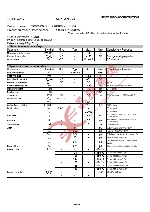
t_str tDJ tRJ tRMS tp-p
tacc
tPJ L(f)
Frequency aging
f_age
Min.
1.6 -40 -50
45 Vcc-0.4 0.8Vcc -
-
-
-
-
-3 -
Typ. 12.288000
-
-
-
0 2.4 2.3 20
2.5
0.79 -
-98 -126 -147 -155 -158 -159
12 250pcs / Reel
Code 13 00
The recommended code is "00"
Condition 500pcs / Reel 1000pcs / Reel
3 Page
[ 2 ] Taping specification Subject to EIA-481 & IEC-60286
Off set Frequency: 12kHz to 20MHz, Vcc=3.3V
Off set 10Hz Vcc=3.3V Off set 100Hz Vcc=3.3V Off set 1kHz Vcc=3.3V Off set 10kHz Vcc=3.3V Off set 100kHz Vcc=3.3V Off set 1MHz Vcc=3.3V @+25ºC first year -
ST or OE
OUT
Test Point L_CMOS
swich
A
supply
VCC by-pass capacitor
GND
ST or OE
OUT
Test Point
*Current consumption under the disable function should be = GND.
爱普生osc有源晶振 SG-9101CB晶体振荡器 规格书资料

►Designed for automotive applications such as Car Multimedia, Body Electronics, Remote Keyless Entry etc.
►Designed for automotive applications related to driving safety (Engine Control Unit, Air Bag, ESC etc ).
NOTICE:PLEASE READ CAREFULLY BELOW BEFORE THE USE OF THIS DOCUMENT ©Seiko Epson Corporation 2020 ――――――――――――――――――――――――――――――――――――――――――――――――――――
1. The content of this document is subject to change without notice. Before purchasing or using Epson products, please contact with sales representative of Seiko Epson Corporation (“Epson”) for the latest information and be always sure to check the latest information published on Epson’s official web sites and resources.
All of our major manufacturing and non-manufacturing sites, in Japan and overseas, completed the acquisition of ISO 14001
爱普生 EPSON 温补晶振 TG-5006CE-39L 32.000000MHz规格参数、数据手册、规格书信息

*2 Measured in the elapse of 24 hours after reflow soldering.
*3 Vcc +/- 5% must be in operating supply voltage range (1.7 V to 3.465 V)
2
[ 5 ] Electrical characteristics
3
[ 6 ] Test circuit
1) Output Load : Load_R // Load_C = 10 kΩ // 10 pF
Supply Voltage
By-pass Capacitor
0.01 to 0.1 F
Vcc N.C.
OUT
DC-cut Capacitor
GND
Load_C
fo
-
32
-
MHz
Frequency tolerance
f_tol
-1.0
-
+1.0
x10⁻⁶
T_use=+25°C+/-2°C Before reflow
Frequency tolerance *1
f_tol
-2.0
-
+2.0
x10⁻⁶
T_use=+25°C+/-2°C After 2 reflows *2
To maintain stable operation, provide a 0.01 to 0.1 μF by-pass capacitor at a location as near as possible to the power source terminal of the crystal product (between Vcc - GND).
爱普生TG-3530SA晶体振荡器(TCXO)规格书
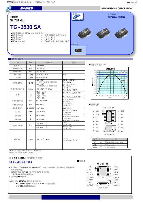
实际尺寸
规格(特征)
项目 输出频率 振荡输出电压 温度补偿电压 储存温度 工作温度 频率温度特征 符号 规格说明 32.768kHz 1.5V~5.5V 2.2V~5.5V 55C~+125C 40C~+85C 3.810-6 相当于每月 10 秒钟的偏差 5.0106 相当于每月 13 秒钟的偏差 1.010 /V Max.
关于在目录内使用的记号
●无铅。 ●符合欧盟 RoHS 指令。 欧盟 RoHS 指令免检的含铅产品。 (密封玻璃、高温熔化性焊料或其他材料中包含铅。 ) ●适合车用途开发了,高可靠性的产品
注意事项
·本材料如有变更,恕不另行通知。量产设计时请确认最新信息。 ·未经 Seiko Epson 公司书面授权,禁止以任何形式或任何方式复制或者发布本材料中任何部分的信息内容。 ·本材料中的书面信息、应用电路、编程、使用等内容仅供参考。Seiko Epson 公司对第三方专利或版权的侵权行为不负有任何责任。本材料 未对任何专利或知识版权的许可权进行授权。 ·本材料中规格表中的数值大小通过数值线上的大小关系表示。 ·当出口此材料中描述的产品或技术时,你应该遵守相应的出口管制法律和法规,并按照这些法律和法规的要求执行。 请不要将产品(以及任何情况下提供任何的技术信息)用于开发或制造大规模杀伤性武器或其他军事用途。还要求,不要将产品提供给任何 将产品用于此类违禁用途的第三方。 ·此类产品是基于在一般电子机械内使用而设计开发的,如将产品应用于需要极高可靠性的特定用途,必须实现得到弊公司的事前许可。若 无许可弊公司将不负任何责任。 1.太空设备(人造卫星、火箭等) 2.运输车辆机器控制装置(汽车、飞机、火车、船舶等) 3.用于维持生命的医疗器械 4.海底中转设备 5.发电站控制机器 6.防灾防盗装置 7.交通设备 8.其他,用于与 1~7 具有同等可靠性的用途。
爱普生晶振SG-3030CM晶体振荡器规格书

-40 °C ~ +85 °C +5±23 × 10-6
+10 × 10-6 / -120 × 10-6 ±2 × 10⁻⁶ / V Max.
2 µA Max.
45 % ~ 55 %
输出电压
VOH VOL
输出负载条件(CMOS) L_CMOS
VIO -0.4V Min. 0.4V Max. 15 pF Max.
未对任何专利或知识版权的许可权进行授权。 ·本材料中规格表中的数值大小通过数值线上的大小关系表示。 ·当出口此材料中描述的产品或技术时,你应该遵守相应的出口管制法律和法规,并按照这些法律和法规的要求执行。
请不要将产品(以及任何情况下提供任何的技术信息)用于开发或制造大规模杀伤性武器或其他军事用途。还要求,不要将产品提供给任何 将产品用于此类违禁用途的第三方。 ·此类产品是基于在一般电子机械内使用而设计开发的,如将产品应用于需要极高可靠性的特定用途,必须实现得到弊公司的事前许可。若 无许可弊公司将不负任何责任。
1.太空设备(人造卫星、火箭等) 2.运输车辆机器控制装置(汽车、飞机、火车、船舶等) 3.用于维持生命的医疗器械 4.海底中转设备 5.发电站控制机器 6.防灾防盗装置 7.交通设备 8.其他,用于与 1~7 具有同等可靠性的用途。
本材料中记载的品牌名称或产品名称是其所有人的商标或注册商标。
Seiko Epson Corporation
CD RF
CG
V IO OUT
GND
条件
裸存 +25 °C, VCC=3.3V -20 °C ~ +70 °C (+25 C 为基准温度) +25 °C, 3.3V, 无负载条件 1/2VCC(VIO) 级别 IOH=-0.4mA IOL= 0.4mA CMOS 负载 CMOS 负载:20 % VCC(VIO) ~ 80 % VCC(VIO) 级别 电源电压最低时,所需时间为 0 秒. +25 °C +25 °C,VCC=3.3 V, 第一年
爱普生 EH—TW5500投影机

因为即使光圈设于 快速”档位,在某些
T 50 W5 0 的均匀性始终没有低于9 %和 场景的亮度变化还是赶不上画面的变化 。 44
照 先是 亮 度 测 试 。 这 次T 5 0 测 9 %.这一数据.还略高于T 5 0 W 50 59 w4 0 的实
所以即使是爱普生也只在动态模式下应 用
T 50 W5 0 的外形和T 5 0 W4 0 基本没有 到产品价格上的话.那就更是善奠大焉 无论如何.从菜单的 变化 .虢们知
在 短 短 半 年时 间 里 , 爱普 生 又 在 产 品中 加 不同,身高体重完全一样,规格数据就像
人 了更先进的技术,提高了性能吗?从爱 是直接拷贝过来一样。仅有的不同点,是 道T 5 0 W5 0 的改教.都是属于固件层次的 W5 0 视 普生官方公布的规梏参数 .我们并没有发 机身左右两侧挡板.被饰以与主机部分完 小升级.你 可以把T 5 0 为升级了固 现T 5 0 W5 0 的性能有任何提升 .特¥ 是最 全不同的灰色。要想不把再者搞锗 .外观 件的T 5 0 Ⅱ W4 0 。至于是否春消费者愿意为 荚键的对比度.这往往是家庭 髟院投影机 上也就只有这点提示了。 升级的重要指标 ,仍然和T 5 0 w4 0 一样保
亮度。#T 5 0 t W4 0 的样机稍低一些。
5 左 测值 ( 43 9 %和9 % ) 这是爱普生制造 动 态 光 圈 。 而 3 0 1 右 的 同 屏 对 比 度 29
充的 动态 模式测到的光通■刚超 品质的明证之一.无愧于 精工”之名。
底对T 5 0 W4 0 的测试 ,我们已经知道,以
T 50 W4 0 的性能 .足以作为爱普生家庭髟 院投影机的旗舰而毫无愧色。然而时间未
EPSON CB-PU2220B 激光工程投影机 产品规格手册

专业可靠 灵活易用CB-PU2220B 3LCD 激光工程投影机激光光源20,000小时免维护*2超高原生对比度选配外置摄像头,画面自动调节密封光源与光学引擎,易维护多种选配电动镜头*3紧凑机身设计,重量仅24.4kgIP5 防尘等级*1*8得益于爱普生家庭影院投影机中研发的相同技术,一种特殊光学部件的使用可以调整偏振角度的偏差,以提高原生对比度,即使在剧院等黑暗环境中使用,也能显示出真正的黑色。
高对比度场景自适应Gamma 校正功能是爱普生自主研发的画质调节功能,可以根据图片内容逐帧分析图像,自动调整Gamma 值,以更佳对比度投射。
场景自适应Gamma 校正令人惊叹的画质无特殊光学部件有特殊光学部件LCD 液晶板LCD 液晶板特殊光学部件OFF ON 4K 增强*8分辨率爱普生的4K 增强*8技术将像素点斜向双倍增强达到分辨率加倍的效果,使画面更加清晰生动。
注:模拟图片高动态范围图像:关高动态范围图像:开HDR 高动态范围图像技术CB-PU2200/2100系列支持HDR10和HLG 标准,可在宽色调范围内实现动态输出,并有效的降低黑色和白色斑点。
OFF ON本宣传页中的数据,来源于爱普生实验室数据,与实际使用数据存在差异,彩页中技术更高的稳定性CB-PU2220B 激光工程投影机CB-PU2220B 为爱普生全新升级高亮度激光工程投影机,亮度提升至20,000流明*5*6,采用激光光源,无机液晶面板和无机荧光轮,实现持久可靠的高质量投影。
激光光源可以达到20,000小时免维护*1*2,并投影精准白色高光。
3LCD 技术及WUXGA 分辨率为用户带来精美画质。
内置色彩校正系统,保证长时间使用后,光输出均匀性一致。
支持多种电动选配镜头,最短实现0.35投射比,搭配选配外置摄像头可实现画面自动校正,满足不同场景及不同大小的空间应用。
CB-PU2200/2100系列配备符合IEC 标准的IP5X*认证光学引擎和激光光源模块,提供出色的防尘保护。
爱普生 EPSON 表晶谐振器 MC-306 32.768000kHz规格参数、数据手册、规格书信息
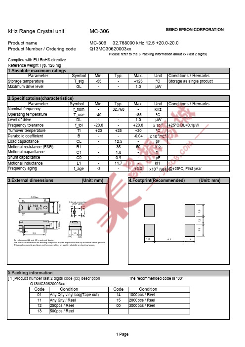
kHz Range Crystal unitMC-306Product nameMC-306 32.768000 kHz 12.5 +20.0-20.0Product Number / Ordering codeQ13MC30620003xxPlease refer to the 5.Packing information about xx (last 2 digits)Complies with EU RoHS directiveReference weight Typ. 126 mg1.Absolute maximum ratingsSymbolMin.Typ.Max.UnitConditions / RemarksStorage temperature T_stg -55-+125ºC Storage as single productGL--1.0µW2.Specificatoins(characteristics)SymbolMin.Typ.Max.Unit Conditions / Remarksf_nom -32.768-kHz T_use -40-+85ºC DL -- 1.0 µWf_tol -20.0-+20.0x 10⁻⁶+25ºC DL=0.1µW Ti +20+25+30ºC B ---0.04x 10⁻⁶/ºC 2CL -12.5-pF R1-3550k ΩC1- 1.8-fF C0-0.9-pF Motional inductance L1-11.7-kHf_age-3-+3.0x10⁻⁶ /yea @+25ºC, First year3.External dimensions (Unit: mm)4.Footprint(Recommended) (Unit: mm)5.Packing information[ 1 ]Product number last 2 digits code (xx) descriptionThe recommended code is "00"Q13MC30620003xxCodeCode01Any Q'ty vinyl bag(Tape cut)141000pcs / Reel 11Any Q'ty / Reel 152000pcs / Reel 12250pcs / Reel 003000pcs / Reel13500pcs / ReelShunt capacitance Frequency agingConditionConditionFrequency tolerance Turnover temperature Parabolic coefficient Load capacitanceMotional resistance (ESR)Motional capacitance Level of driveParameterMaximum drive levelParameter Nominal frequencyOperating temperatureThe metal case inside of the molding compound may be exposed on the top or bottom of this product. This purely cosmetic and does not have any effect on quality, reliability or electrical specs.Do not connect #2 and #3 to external device.Internal connection(TOP VIEW)#4#1#2#3 1.9(0.9)(0.9)5.50.52.54 M a x .2.388.0 Max.#4#1 #2#33.8 M a x .3.232.768 k E 5711.9 1.91.3 4.2 1.3 1.3[ 2 ] Taping specificationSubject to EIA-481 & IEC-60286(1) Tape dimensions TE1608L Material of the Carrier Tape : PS Material of the Top Tape : PET+PEUnit: mm(2) Reel dimensionsMaterial of the Reel : PSUnit: mm4.0±0.12.0±0.18.0±0.110P: 40±0.17.5±0.116.0±0.31.75±0.18.5±0.10.3±0.05 2.7±0.14.1±0.1 +0.1 φ1.5-0+0.1φ1.5-05︒ Max.5︒ Max.Top TapeReflow profilePre Heating TemperatureTp1 ~ Tp2 = + 170 °CHeating TemperatureTMlt = + 220 °CPeek TemperatureTMax. = + 260 °CPoint of measuringIn case of Solder abilityTerminal.In case of Resistance to soldering heatSurface.Noticet(time)TmltTp2Tp1100s+220ºC+260ºCTMax.Temperature35s· This material is subject to change without notice.· Any part of this material may not be reproduced or duplicated in any form or any means without the writtenpermission of Seiko Epson.· The information about applied data,circuitry, software, usage, etc. written in this material is intended forreference only.Seiko Epson does not assume any liability for the occurrence of customer damage or infringing on any patent or copyright of a third party.This material does not authorize the licensing for any patent or intellectual copyrights.· When exporting the products or technology described in this material, you should comply with the applicableexport control laws and regulations and follow the procedures required by such laws and regulations.· You are requested not to use the products (and any technical information furnished, if any) for the development and/or manufacture of weapon of mass destruction or for other military purposes. You are also requested that youwould not make the products available to any third party who may use the products for such prohibitedpurposes.· These products are intended for general use in electronic equipment. When using them in specific applications that requireextremely high reliability, such as the applications stated below, you must obtain permission from Seiko Epson in advance./ Space equipment (artificial satellites, rockets, etc.)/ Transportation vehicles and related (automobiles, aircraft, trains, vessels, etc.)/ Medical instruments to sustain life/ Submarine transmitters/ Power stations and related/ Fire work equipment and security equipment/ Traffic control equipment/ And others requiring equivalent reliability.· All brands or product names mentioned herein are trademarks and/or registered trademarks of their respective.。
Skyworks Solutions Si530 531晶体振荡器说明书

Si530/531C RYSTAL O SCILLATOR (XO) (10MH Z TO 1.4GH Z )FeaturesApplicationsDescriptionThe Si530/531 XO utilizes Skyworks Solutions’ advanced DSPLL ®circuitry to provide a low jitter clock at high frequencies. The Si530/531 is available with any-rate output frequency from 10 to 945MHz and select frequencies to 1400MHz. Unlike a traditional XO, where a different crystal is required for each output frequency, the Si530/531 uses one fixed crystal to provide a wide range of output frequencies. This IC based approach allows the crystal resonator to provide exceptional frequency stability and reliability. In addition,DSPLL clock synthesis provides superior supply noise rejection, simplifying the task of generating low jitter clocks in noisy environments typically found in communication systems. The Si530/531 IC based XO is factory configurable for a wide variety of user specifications including frequency, supply voltage,output format, and temperature stability. Specific configurations are factory programmed at time of shipment, thereby eliminating long lead times associated with custom oscillators.Functional Block Diagram⏹Available with any-rate output frequencies from 10MHz to 945MHz and select frequencies to 1.4GHz⏹3rd generation DSPLL ® with superior jitter performance⏹3x better frequency stability thanSAW-based oscillators⏹Internal fixed crystal frequency ensures high reliability and low aging⏹Available CMOS, LVPECL, LVDS, and CML outputs⏹ 3.3, 2.5, and 1.8V supply options ⏹Industry-standard 5x 7mm package and pinout⏹Pb-free/RoHS-compliant⏹SONET/SDH ⏹Networking ⏹SD/HD video⏹Test and measurement ⏹Clock and data recovery⏹FPGA/ASIC clock generationOrdering Information:See page 8.R EVISION DSi530/531T ABLE OF C ONTENTS1. Electrical Specifications . . . . . . . . . . . . . . . . . . . . . . . . . . . . . . . . . . . . . . . . . . . . . . . . . . .32. Pin Descriptions . . . . . . . . . . . . . . . . . . . . . . . . . . . . . . . . . . . . . . . . . . . . . . . . . . . . . . . . . .73. Ordering Information . . . . . . . . . . . . . . . . . . . . . . . . . . . . . . . . . . . . . . . . . . . . . . . . . . . . . .84. Outline Diagram and Suggested Pad Layout . . . . . . . . . . . . . . . . . . . . . . . . . . . . . . . . . .95. Si530/Si531 Mark Specification . . . . . . . . . . . . . . . . . . . . . . . . . . . . . . . . . . . . . . . . . . . . .106. 6-Pin PCB Land Pattern . . . . . . . . . . . . . . . . . . . . . . . . . . . . . . . . . . . . . . . . . . . . . . . . . . .11 Document Change List . . . . . . . . . . . . . . . . . . . . . . . . . . . . . . . . . . . . . . . . . . . . . . . . . . . . .12 Contact Information . . . . . . . . . . . . . . . . . . . . . . . . . . . . . . . . . . . . . . . . . . . . . . . . . . . . . . . .13 2SkyworksSolutions,Inc.•Phone[781]376-3000•Fax[781]376-3100•*********************•Si530/531SkyworksSolutions,Inc.•Phone[781]376-3000•Fax[781]376-3100•*********************•31. Electrical SpecificationsTable 1. Recommended Operating ConditionsParameterSymbol Test Condition Min Typ Max Unit Supply Voltage 1V DD3.3V option 2.97 3.3 3.63V 2.5V option 2.25 2.5 2.75V 1.8V option1.71 1.8 1.89VSupply CurrentI DDOutput enabledLVPECL CML LVDS CMOS ————1119990811211089888mATristate mode—6075mA Output Enable (OE)2V IH 0.75x V DD——V V IL——0.5V Operating Temperature RangeT A–40—85ºCNotes:1.Selectable parameter specified by part number. See Section 3. "Ordering Information" on page 8 for further details.2. OE pin includes a 17 k pullup resistor to V DD .Table 2. CLK± Output Frequency CharacteristicsParameterSymbol Test Condition Min Typ Max Unit Nominal Frequency 1,2f OLVPECL/LVDS/CML10—945MHz CMOS10—160MHz Initial Accuracy f iMeasured at +25°C at time ofshipping—±1.5—ppmTemperature Stability 1,3–7–20–50———+7+20+50ppm Agingf aFrequency drift over first year ——±3ppm Frequency drift over 20 yearlife——±10ppmNotes:1.See Section 3. "Ordering Information" on page 8 for further details.2. Specified at time of order by part number. Also available in frequencies from 970 to 1134MHz and 1213 to 1417MHz.3. Selectable parameter specified by part number.4. Time from powerup or tristate mode to f O .Si530/5314SkyworksSolutions,Inc.•Phone[781]376-3000•Fax[781]376-3100•*********************•Total StabilityTemp stability =±7ppm ——±20ppm Temp stability =±20ppm ——±31.5ppm Temp stability =±50ppm——±61.5ppm Powerup Time 4t OSC——10msTable 3. CLK± Output Levels and SymmetryParameterSymbol Test ConditionMin Typ Max Unit LVPECL Output Option 1V O mid-level V DD – 1.42—V DD – 1.25V V OD swing (diff) 1.1— 1.9V PP V SEswing (single-ended)0.55—0.95V PP LVDS Output Option 2V O mid-level 1.125 1.20 1.275V V ODswing (diff)0.50.70.9V PPCML Output Option 2V O2.5/3.3V option mid-level —V DD – 1.30—V 1.8V option mid-level —V DD – 0.36—V V OD2.5/3.3V option swing (diff) 1.10 1.50 1.90V PP 1.8V option swing (diff)0.350.4250.50V PP CMOS Output Option 3V OH I OH =32mA 0.8x V DD—V DDV V OLI OL =32mA——0.4VRise/Fall time (20/80%)t R, t FLVPECL/LVDS/CML ——350ps CMOS with C L =15pF—1—nsSymmetry (duty cycle)SYMLVPECL:V DD – 1.3V (diff)LVDS: 1.25V (diff)CMOS:V DD /245—55%Notes:1.50 Ω to V DD –2.0 V.2. R term = 100 Ω (differential).3. C L = 15 pFTable 2. CLK± Output Frequency Characteristics (Continued)ParameterSymbolTest Condition Min Typ Max Unit Notes:1.See Section 3. "Ordering Information" on page 8 for further details.2. Specified at time of order by part number. Also available in frequencies from 970 to 1134MHz and 1213 to 1417MHz.3. Selectable parameter specified by part number.4. Time from powerup or tristate mode to f O .Si530/531SkyworksSolutions,Inc.•Phone[781]376-3000•Fax[781]376-3100•*********************•5Table 4. CLK± Output Phase JitterParameterSymbolTest Condition Min Typ Max Unit Phase Jitter (RMS)1for F OUT > 500 MHz φJ 12kHz to 20MHz (OC-48)—0.250.40ps 50kHz to 80MHz (OC-192)—0.260.37ps Phase Jitter (RMS)1for F OUT of 125 to 500MHz φJ 12kHz to 20MHz (OC-48)—0.360.50ps 50kHz to 80MHz (OC-192)2—0.340.42ps Phase Jitter (RMS)for F OUT of 10 to 160MHz CMOS Output OnlyφJ12kHz to 20MHz (OC-48)2—0.62—ps 50kHz to 20MHz 2—0.61—psNotes:1.Refer to AN256 for further information.2. Max offset frequencies: 80MHz for FOUT > 250MHz, 20MHz for 50MHz < FOUT <250MHz,2MHz for 10MHz < FOUT <50MHz.Table 5. CLK± Output Period JitterParameterSymbol Test ConditionMin Typ Max Unit Period Jitter*J PERRMS —2—ps Peak-to-Peak—14—ps*Note: Any output mode, including CMOS, LVPECL, LVDS, CML. N =1000 cycles. Refer to AN279 for further information.Table 6. CLK± Output Phase Noise (Typical)Offset Frequency (f)120.00MHz LVDS 156.25MHz LVPECL 622.08MHz LVPECL Unit100Hz 1kHz 10kHz 100kHz 1MHz 10MHz 100MHz–112–122–132–137–144–150n/a–105–122–128–135–144–147n/a–97–107–116–121–134–146–148dBc/HzSi530/531Table 7. Environmental ComplianceThe Si530/531 meets the following qualification test requirements.Parameter Conditions/Test MethodMechanical Shock MIL-STD-883, Method 2002 Mechanical Vibration MIL-STD-883, Method 2007 Solderability MIL-STD-883, Method 2003Gross & Fine Leak MIL-STD-883, Method 1014 Resistance to Solder Heat MIL-STD-883, Method 2036Moisture Sensitivity Level J-STD-020, MSL1Contact Pads Gold over NickelTable 8. Thermal Characteristics(Typical values TA=25ºC, V DD=3.3V)Parameter Symbol Test Condition Min Typ Max Unit Thermal Resistance Junction to AmbientθJA Still Air—84.6—°C/W Thermal Resistance Junction to CaseθJC Still Air—38.8—°C/W Ambient Temperature T A–40—85°C Junction Temperature T J——125°CTable 9. Absolute Maximum Ratings1Parameter Symbol Rating Unit Maximum Operating Temperature T AMAX85ºC Supply Voltage, 1.8V Option V DD–0.5 to +1.9V Supply Voltage, 2.5/3.3V Option V DD–0.5 to +3.8VInput Voltage (any input pin)V I–0.5 to V DD +0.3V Storage Temperature T S–55 to +125ºCESD Sensitivity (HBM, per JESD22-A114)ESD2500V Soldering Temperature (Pb-free profile)2T PEAK260ºC Soldering Temperature Time @ T PEAK (Pb-free profile)2t P20–40seconds Notes:1.Stresses beyond those listed in Absolute Maximum Ratings may cause permanent damage to the device. Functionaloperation or specification compliance is not implied at these conditions. Exposure to maximum rating conditions for extended periods may affect device reliability.2. The device is compliant with JEDEC J-STD-020C. Refer to Si5xx Packaging FAQ available for download at/en/application-pages/timing-lookup-customize for further information, including solderingprofiles.6SkyworksSolutions,Inc.•Phone[781]376-3000•Fax[781]376-3100•*********************•Si530/531SkyworksSolutions,Inc.•Phone[781]376-3000•Fax[781]376-3100•*********************•72. Pin DescriptionsTable 10. Pinout for Si530 SeriesPin Symbol LVDS/LVPECL/CML FunctionCMOS Function1OE (CMOS only)*No connectionOutput enable0=clock output disabled (outputs tristated)1=clock output enabled2OE(LVPECL,LVDS,CML)*Output enable0=clock output disabled (outputs tristated)1=clock output enabledNo connection 3GND Electrical and Case GroundElectrical and Case Ground4CLK+Oscillator Output Oscillator Output 5CLK–Complementary Output No connection 6V DDPower Supply VoltagePower Supply Voltage*Note: OE includes a 17 k Ω pullup resistor to V DD .Table 11. Pinout for Si531 SeriesPin SymbolLVDS/LVPECL/CML Function 1OE (LVPECL, LVDS, CML)*Output enable0=clock output disabled (outputs tristated)1=clock output enabled2No connectionNo connection 3GND Electrical and Case Ground4CLK+Oscillator Output 5CLK–Complementary output 6V DDPower Supply Voltage*Note: OE includes a 17 k Ω pullup resistor to V DD.GNDNC V DDCLKNC O E (Top View)GNDO E V DDCLK+CLK–NC GNDNC V DDCLK+CLK–O E Si530LVDS/LVPECL/CMLSi530CMOSSi531LVDS/LVPECL/CMLSi530/5313. Ordering InformationThe Si530/531 XO supports a variety of options including frequency, temperature stability, output format, and V DD. Specific device configurations are programmed into the Si530/531 at time of shipment. Configurations can be specified using the Part Number Configuration chart below. Skyworks Solutions provides a web browser-based part number configuration utility to simplify this process.Refer to /en/application-pages/timing-lookup-customize to access this tool and for further ordering instructions. The Si530 and Si531 XO series are supplied in an industry-standard, RoHS compliant, 6-pad, 5x7 mm package. The Si531 Series supports an alternate OE pinout (pin #1) for the LVPECL, LVDS, and CML output formats. See Tables 10 and 11 for the pinout differences between the Si530 and Si531 series.Example P/N: 530AB622M080DGR is a 5 x 7 XO in a 6 pad package. The frequency is 622.080 MHz, with a 3.3 V supply, LVPECL output,and Output Enable active high polarity. Temperature stability is specifed as ±20 ppm. The part is specified for –40 to +85 °C ambient temperature range operation and is shipped in tape and reel format.Figure1.Part Number Convention8SkyworksSolutions,Inc.•Phone[781]376-3000•Fax[781]376-3100•*********************•Si530/531SkyworksSolutions,Inc.•Phone[781]376-3000•Fax[781]376-3100•*********************•94. Outline Diagram and Suggested Pad LayoutFigure 2 illustrates the package details for the Si530/531. Table 12 lists the values for the dimensions shown in the illustration.Figure 2.Si530/531 Outline Diagram Table 12. Package Diagram Dimensions (mm)DimensionMin Nom Max A 1.50 1.65 1.80b 1.30 1.40 1.50c 0.500.600.70D 5.00 BSC D1 4.304.40 4.50e 2.54 BSC E 7.00 BSC E1 6.10 6.20 6.30H 0.550.650.75L 1.17 1.27 1.37L10.050.100.15p 1.80— 2.60R 0.70 REF aaa 0.15bbb 0.15ccc 0.10ddd 0.10eee0.05Notes:1.All dimensions shown are in millimeters (mm) unlessotherwise noted.2.Dimensioning and Tolerancing per ANSI Y14.5M-1994.Si530/53110SkyworksSolutions,Inc.•Phone[781]376-3000•Fax[781]376-3100•*********************•5. Si530/Si531 Mark SpecificationFigure 3 illustrates the mark specification for the Si530/Si531. Table 13 lists the line information.Figure 3.Mark Specification Table 13. Si53x Top Mark DescriptionLine Position Description1 1–10Part Family Number, 53x (First 3 characters in part number where x = 0 indicates a 530 device and x = 1 indicates a 531 device). 21–10Si530, Si531: Option1+Option2+Freq(7)+Temp Si532, Si533, Si534, Si530/Si531 w/ 8-digit resolution: Option1+Option2+ConfigNum(6)+Temp3Trace Code Position 1Pin 1 orientation mark (dot)Position 2Product Revision (D)Position 3–6Tiny Trace Code (4 alphanumeric characters per assembly release instructions)Position 7Year (least significant year digit), to be assigned by assembly site (ex: 2007=7)Position 8–9Calendar Work Week number (1–53), to be assigned by assembly site Position 10“+” to indicate Pb-Free and RoHS-compliantSi530/531SkyworksSolutions,Inc.•Phone[781]376-3000•Fax[781]376-3100•*********************• 116. 6-Pin PCB Land PatternFigure 4 illustrates the 6-pin PCB land pattern for the Si530/531. Table 14 lists the values for the dimensions shown in the illustration.Figure 4.Si530/531 PCB Land Pattern Table 14. PCB Land Pattern Dimensions (mm)Dimension(mm)C1 4.20E 2.54X1 1.55Y11.95Notes:General1.All dimensions shown are in millimeters (mm) unless otherwise noted.2. Dimensioning and Tolerancing is per the ANSI Y14.5M-1994 specification.3. This Land Pattern Design is based on the IPC-7351 guidelines.4. All dimensions shown are at Maximum Material Condition (MMC). Least MaterialCondition (LMC) is calculated based on a Fabrication Allowance of 0.05mm.Solder Mask Design1.All metal pads are to be non-solder mask defined (NSMD). Clearance betweenthe solder mask and the metal pad is to be 60 µm minimum, all the way aroundthe pad.Stencil Design1. A stainless steel, laser-cut and electro-polished stencil with trapezoidal wallsshould be used to assure good solder paste release.2. The stencil thickness should be 0.125mm (5 mils).3. The ratio of stencil aperture to land pad size should be 1:1.Card Assembly1. A No-Clean, Type-3 solder paste is recommended.2.The recommended card reflow profile is per the JEDEC/IPC J-STD-020specification for Small Body Components.Si530/53112SkyworksSolutions,Inc.•Phone[781]376-3000•Fax[781]376-3100•*********************•D OCUMENT C HANGE L ISTRevision 0.4 to Revision 0.5⏹Updated Table 1, “Recommended Operating Conditions,” on page 3.● Added maximum supply current specifications.● Specified relationship between temperature at startupand operation temperature.⏹Updated Table 4, “CLK± Output Phase Jitter,” on page 5 to include maximum rms jitter generation specifications and updated typical rms jitter specifications.⏹Added Table 6, “CLK± Output Phase Noise (Typical),” on page 5.⏹Added Output Enable active polarity as an option in Figure 1, “Part Number Convention,” on page 8.Revision 0.5 to Revision 1.0⏹Updated Note 3 in Table 1, “Recommended Operating Conditions,” on page 3.⏹Updated Figure 1, “Part Number Convention,” on page 8.Revision 1.0 to Revision 1.1⏹Updated Table 1, “Recommended Operating Conditions,” on page 3.● Device maintains stable operation over –40 to +85ºCoperating temperature range.● Supply current specifications updated for revision D.⏹Updated Table 2, “CLK± Output Frequency Characteristics,” on page 3.● Added specification for ±20ppm lifetime stability(±7ppm temperature stability) XO.⏹Updated Table 3, “CLK± Output Levels and Symmetry,” on page 4.● Updated LVDS differential peak-peak swingspecifications.⏹Updated Table 4, “CLK± Output Phase Jitter,” on page 5.⏹Updated Table 5, “CLK± Output Period Jitter,” on page 5.● Revised period jitter specifications.⏹Updated Table 9, “Absolute Maximum Ratings 1,” on page 6 to reflect the soldering temperature time at 260ºC is 20–40sec per JEDEC J-STD-020C.⏹Updated 3. "Ordering Information" on page 8.● Changed ordering instructions to revision D.⏹Added 5. "Si530/Si531 Mark Specification" on page 10.Revision 1.1 to Revision 1.2⏹Updated 2.5V/3.3V and 1.8V CML output level specifications for Table 3 on page 4.⏹Added footnotes clarifying max offset frequency test conditions for Table 4 on page 5.⏹Added CMOS phase jitter specs to Table 4 on page 5.⏹Removed the words "Differential Modes:LVPECL/LVDS/CML" in the footnote referring to AN256 in Table 4 on page 5.⏹Separated 1.8V, 2.5V/3.3V supply voltage specifications in Table 9 on page 6.⏹Updated and clarified Table 9 on page 6 to include the "Moisture Sensitivity Level" and "Contact Pads" rows.⏹Updated Figure 3 on page 10 and Table 13 on page 10 to reflect specific marking information. Previously, Figure 3 was generic.Revision 1.2 to Revision 1.3⏹Added Table 8, “Thermal Characteristics,” on page 6.Revision 1.3 to Revision 1.4⏹Revised Figure 2 and Table 12 on page 9 to reflect current package outline diagram.⏹Revised Figure 4 and Table 14 on page 11 to reflect the recommended PCB land pattern.Revision 1.4 to Revision 1.5⏹Changed “Trays” to “Coil Tape” in Ordering Guide.Copyright © 2022 Skyworks Solutions, Inc. All Rights Reserved.Information in this document is provided in connection with Skyworks Solutions, Inc. (“Skyworks”) products or services. These materials, including the information contained herein, are provided by Skyworks as a service to its customers and may be used for informational purposes only by thecustomer. Skyworks assumes no responsibility for errors or omissions in these materials or the information contained herein. Skyworks may change its documentation, products, services, specifications or product descriptions at any time, without notice. Skyworks makes no commitment to update the materials or information and shall have no responsibility whatsoever for conflicts, incompatibilities, or other difficulties arising from any future changes.No license, whether express, implied, by estoppel or otherwise, is granted to any intellectual property rights by this document. Skyworks assumes no liability for any materials, products or information provided hereunder, including the sale, distribution, reproduction or use of Skyworks products, information or materials, except as may be provided in Skyworks’ Terms and Conditions of Sale.THE MATERIALS, PRODUCTS AND INFORMATION ARE PROVIDED “AS IS” WITHOUT WARRANTY OF ANY KIND, WHETHER EXPRESS, IMPLIED,STATUTORY, OR OTHERWISE, INCLUDING FITNESS FOR A PARTICULAR PURPOSE OR USE, MERCHANTABILITY, PERFORMANCE, QUALITY OR NON-INFRINGEMENT OF ANY INTELLECTUAL PROPERTY RIGHT; ALL SUCH WARRANTIES ARE HEREBY EXPRESSL Y DISCLAIMED. SKYWORKS DOES NOT WARRANT THE ACCURACY OR COMPLETENESS OF THE INFORMATION, TEXT, GRAPHICS OR OTHER ITEMS CONTAINED WITHIN THESE MATERIALS. SKYWORKS SHALL NOT BE LIABLE FOR ANY DAMAGES, INCLUDING BUT NOT LIMITED TO ANY SPECIAL, INDIRECT, INCIDENTAL, STATUTORY, OR CONSEQUENTIAL DAMAGES, INCLUDING WITHOUT LIMITATION, LOST REVENUES OR LOST PROFITS THAT MAY RESUL T FROM THE USE OF THE MATERIALS OR INFORMATION, WHETHER OR NOT THE RECIPIENT OF MATERIALS HAS BEEN ADVISED OF THE POSSIBILITY OF SUCH DAMAGE Skyworks products are not intended for use in medical, lifesaving or life-sustaining applications, or other equipment in which the failure of the Skyworks products could lead to personal injury, death, physical or environmental damage. Skyworks customers using or selling Skyworks products for use in such applications do so at their own risk and agree to fully indemnify Skyworks for any damages resulting from such improper use or sale.Customers are responsible for their products and applications using Skyworks products, which may deviate from published specifications as a result of design defects, errors, or operation of products outside of published parameters or design specifications. Customers should include design and operating safeguards to minimize these and other risks. Skyworks assumes no liability for applications assistance, customer product design, or damage to any equipment resulting from the use of Skyworks products outside of Skyworks’ published specifications or parameters.Skyworks, the Skyworks symbol, Sky5®, SkyOne®, SkyBlue™, Skyworks Green™, Clockbuilder®, DSPLL®, ISOmodem®, ProSLIC®, and SiPHY® are trademarks or registered trademarks of Skyworks Solutions, Inc. or its subsidiaries in the United States and other countries. Third-party brands and names are for identification purposes only and are the property of their respective owners. Additional information, including relevant terms and conditions, posted at , are incorporated by reference.SkyworksSolutions,Inc.|Nasdaq:SWKS|*********************|USA: 781-376-3000 | Asia: 886-2-2735 0399 | Europe: 33 (0)1 43548540Portfolio Quality/qualitySW/HW/CBProSupport & Resources/support。
进口晶振料号、尺寸大全.xls
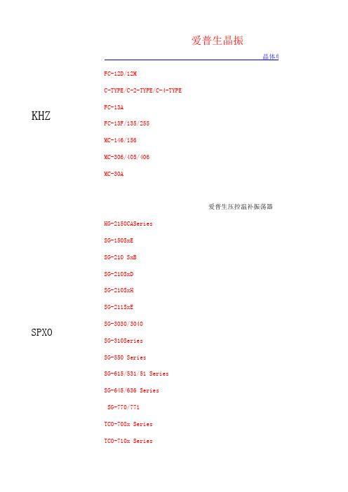
KHZSPXOTCO-710x SeriesSG-770/771TCO-708x Series SG-615/531/51 Series SG-645/636 Series SG-310Series SG-550 Series SG-211SxE SG-3030/3040SG-210SxD SG-210SxH SG-150SxE SG-210 SxB MC-306/405/406 MC-30A爱普生压控温补振荡器HG-2150CASeries FC-13A FC-13F/135/255MC-146/156爱普生晶振晶体单元FC-12D/12MC-TYPE/C-2-TYPE/C-4-TYPE串行RX-8581SA/JE/NB RX-8731LC RX-8803SA/LCRX-5412SF RX-8025SA/NB RX-8571SA/NB/LC RX-4575LC RX-4581NB RX-4803SA/LC RX-4571LC/NB/SA RX-4574LC RTC-8564JE/NB/RX-8564LC RX-4045SA/NBRTC-4543SA/SB RTC-4574SA/JE/NB RTC-4701JE/NBRA-4574SA RA-8565SA RA-8581SA 爱普生实时钟模块32.768KHZRA-4565SA音叉型水晶振动子KHKDS表面封装型振水晶振动子MHZUM-5HC-49/UAT-49UM-4AT-38UM-1SMD-49DMX-38DSX840GA DSX840GT DSX151GAL DSX531SDSX630G DSX321SH DSX530GA DSX321G DSX321SL DSX211AL DSX221SHDSX211A DSX221S DSX211G DSX221G KDS晶振DSX1612ADSR221STHKDS振荡器DSA211SCL (VC-TCXO)DSB211SCL (TCXO)DSB211SCB (TCXO)DSA211SDA (VC-TCXO)DSB211SDA (TCXO)DSB211SDB (TCXO)DSA211SDT (VC-TCXO)DSB211SDT (TCXO)DSA222MAA (VC-TCXO)DSA222MAB (VC-TCXO)DSB222MAA (TCXO)DSB222MAB (TCXO)DSA221SCL (VC-TCXO)DSB221SCL (TCXO)DSB221SCB (TCXO)DSA221SDA (VC-TCXO)DSB221SDB (TCXO)DSB221SDA (TCXO)DSA221SDT (VC-TCXO)DSB221SDT (TCXO)DSA221SJ (VC-TCXO)DSB221SJ (TCXO)DSA321SCL (VC-TCXO)DSB321SCL (TCXO)DSV221SR (1.8V動作タイプ)(VCXO)DSV221SV (2.8V/3.3V 動作タイプ) (VCXO)DSV321SR (1.8V動作タイプ) (VCXO)DSV321SV (2.8V/3.3V 動作タイプ) (VCXO)DSV323SD (HCSL出力) (VCXO)DSV323SJ (LVDS出力) (VCXO)DSV323SK (LV-PECL出力) (VCXO)DSV753HJ (LVDS出力) (VCXO)DSV753HK (LV-PECL出力) (VCXO)DSV753SJ (LVDS出力)(VCXO)DSS753SVC(SSXO)CITIZEN晶振西铁城KHZ晶振CFS-206CMR200TCFS-145CMJ206TCFV-206CM250C西铁城MHZ晶振CSA-310CSA-309HCM49CM309SCS325SCSX-750F CSX-750P CSX-750VNX2012SANX3215SAKHZ谐振器音叉晶振RV-2123-C2精工晶振日本NDK晶振振荡器RV-3029-C2-A RV-3029-C2-BRV-3049-C2-A RV-3049-C2-A RV-3049-C2-B 西铁城晶振振荡器瑞士微晶RV-4162-C7RV-8564-C2NX3215SA NX1612AA NX1612AANX2016SA NX2520SA NX3225GANX5032GA NX5032SA NX1255GB NR-2BNR-2C AT-41CD2京瓷晶振KHZ音叉型号频率尺寸ST2012SB 32.768K 2.0 x 1.2 x 0.6ST3215SB 32.768K3.2 x 1.5 x 0.8石英晶体振荡器KC2520B 32.768K 2.5 x 2.0 x 0.7KC2520M 32.768K 2.5 x 2.0 x 0.7温度-40-125°KC3215A32.768K3.2 x 1.5 x 1.0温度补偿水晶振荡器KT3225T 32.768K3.2 x 2.5 x 1.0TCXOCMOS输出类KC2520B-C11.5~1252.5 x 2.0 x 0.7KHZ谐振器M晶体谐振器SPXO钟用晶体振荡器VCXO晶振KC2520B-C2125~160 2.5 x 2.0 x 0.7KC3225A-C21.5~125 3.2 x2.5 x 0.89(K25-2C)KC5032A-CM 1.789~50 5.0 x 3.2 x 1.2KC5032C-C31.8 ~ 170 5.0 x 3.2 x 1.0(K30-3C)KC5032E-C314.31818~166 5.0 x 3.2 x 1.1KC7050A-C21.8~1257.0 x 5.0 x 1.6(K53-2C)石英晶体振荡器(VCXO)KV5032C-C3 1.5~80 5.0 x 3.2 x 1.0KV7050B-C3 1.5~1707.0 x 5.0 x 1.6石英晶体振荡器(TCXO)KT252013~52 2.5 x 2.0 x 0.8max GPS用KT322513~52 3.2 x 2.5 x 1.0max GPS用 台湾晶技(TXC)32.768KHz贴片频率尺寸9HT732.768K 6.9 x 1.4 x 1.30mm9HT932.768K 4.1 x 1.5 x 0.80mm9HT1032.768K 3.2 x 1.5 x 0.75mm9HT1132.768K 2.0 x 1.2 x 0.60mmMHZ9B 3.2 ~ 90MHz11.5 x 5.0 x 3.68mm49/S9C 3.2 ~ 90MHz12.7 x 4.8 x 3.80mm49/SMD 7A8 ~ 80MHz 5.0 x 3.2 x 1.20mm黑色面7B8 ~ 100MHz 5.0 x 3.2 x 0.90mm7M10 ~ 54MHz 3.2 x 2.5 x 0.70mmAV9.9 ~ 54MHz 3.2 x 2.5 x 0.80mm黑色面8Z12 ~ 54MHz 2.5 x 2.0 x 0.55mm石英振荡器7W 1 ~ 170MHz7 x 5 x 1.3mm7C 1 ~ 150MHz 5 x 3.2 x 1.2mm7X 1 ~ 125MHz 3.2 x 2.5 x 1mm8W 4 ~ 54MHz 2.5 x 2 x 0.8mmVCXO 压控振荡器BK60 ~ 700MHz7 x 5 x 1.3mmCJ60 ~ 200MHz 5 x 3.2 x 1.2mmTCXO 温补振荡器7Q13 ~ 52MHz 3.2 x 2.5 x 1mm7L13 ~ 52MHz 2.5 x 2 x 0.8mmNDK(日本电波工业株式会社)晶体谐振器频率尺寸NX2520SG19.2-54MHZ 2.5*2.0*0.9NX3215SA32.768KHZ 3.2*1.5*0.8NX2520SA16-80MHZ 2.5*2.0*0.5NX3225SA12-150MHZ 3.2*2.5*0.55NX3225GA9.840-50MHZ 3.2*2.5*0.75NX5032GB12-55MHZ 5.0*3.2*1.0NX5032GA8-55MHZ 5.0*3.2*1.3NX5032SD9.75-40MHZ 4.9*3.1*0.9AT-41 3.1375-74.1MHZ11.05*4.7*3.6849/S AT-41CD2 3.1375-74.1MHZ11.4*4.8*4.049/SMD晶体振荡器(SPXO)NZ2520SB 1.5 to 80 2.5×2.0×0.9 NZ2520SB 32.768KHZ 2.5×2.0×0.9 2725N 2.5 to 70 5.0×3.2×1.0 2725T 2.5 to 125 5.0×3.2×1.0 7311S-GF-505P62.5-313MHZ7.0*5.0*1.7温补振荡器(TCXO)NT2520SB13.-52MHZ 2.5*2.0*0.9NT3225SA10-40MHZ 3.2*2.5*1.0NT7050BC19.2-26MHZ7.0*5.0*2.0压控振荡器(VCXO)NV2520SA 1.25-80MHZ 2.5*2.0*0.9 NV3225SA 1.25-80MHZ 3.2*2.5*0.9 NV5032SA38.4-52MHZ 5.0*3.2*1.2 NV7050SA 2.048-700MHZ7.0*5.0*1.6晶体滤波器21E15AB21.4MHZ7.0*5.0*1.35 台湾鸿星(HOSONIC)晶体谐振器频率尺寸2SB12~54MHz 2.5*2.0*0.55mm 3SB12~54MHz 3.2*2.5*0.65mm 5SB10~80MHz 5.0*3.2*0.80mm 6SB8~80MHz 6.0*3.5*1.0mm 7SB6~100MHz7.0*5.0*1.1mm 3FB12~54MHz 3.2*2.5*0.80mm5FA10~80MHz 5.0*3.2*1.20mm黑色面两个脚8FA6~80MHz8.0*4.5*1.60mmHC-49SA 3.2~66MHz11.05*4.65*3.50mmHC-49SB8~66MHz11.05*4.65*2.5mmHC-49SMB8~66MHz12.9*4.7*3.2mmHC-49SMA 3.2~66MHz12.9*4.7*4.2mmDT-2630~100KHzDT-3830~100KHz石英振荡器HXO-31~133MHz7.0*5.0*1.5mmHXO-51~133MHz 5.0*3.2*1.3mmHXO-S1~54MHz 3.2*2.5*1.2mmHXO-N1~54MHz 2.5*2.0*0.9mm台湾希华晶振(SIWARD)晶体谐振器频率尺寸LP-2.5 3.5 ~ 80 MHz11.05 x 4.65 x H49/SLP-3.5 3.5 ~ 80 MHz11.05 x 4.65 x HLP-3.5S 3.5 ~ 80 MHz12.3 x 4.7 x H49/SMDLP-4.2S 3.5 ~ 80 MHz12.3 x 4.7 x HSX-252012 ~ 66 MHz 2.5 x 2.0 x 0.55SX-322510 ~ 125 MHz 3.2 x 2.5 x 0.8SX-50328 ~ 100 MHz 5.0 x 3.2 x 0.7SX-60358 ~ 50 MHz 6.0 x 3.5 x 1.0SX-7050 6 ~ 100 MHz7.0 x 5.0 x 1.1GX-3225410 ~ 54 MHz 3.2 x 2.5 x 0.8黑色面四脚GX-503228 ~ 60 MHz 5.0 x 3.2 x 1.1黑色面两脚和四脚GX-50324GX-603528 ~ 60 MHz 6.0 x 3.5 x 1.1黑色面两脚和四脚GX-60354GX-705026 ~ 70 MHz7.0 x 5.0 x 1.4黑色面两脚和四脚GX-70504石英振荡器SHO-3225 2.5 ~ 60 MHz 3.2 x 2.5 x 0.9OSC73 2.5 ~ 60 MHz 5.0 x 3.2 x 1.05OSC57A40 ~ 160 MHz7.0 x 5.0 x 1.5SPO-2520B 1 ~ 200 MHz 2.5x2.0x0.8SPO-3225B 1 ~ 200 MHz 3.2x2.5x0.9SPO-5032B 1 ~ 200 MHz 5.0x3.2x0.9SPO-7050B 1 ~ 200 MHz7.0x5.0x1.4温补振荡器(TCXO)TXO928 ~ 45 MHz 3.2 x 2.5 x 0.9TXO83 6 ~ 45 MHz 5.0 x 3.2 x 1.05STO-2520B0.675 ~ 55 MHz 2.5 x 2.0 x 0.9STO-3225B0.675 ~ 55 MHz 3.2 x 2.5 x 1.0STO-5032B0.675 ~ 55 MHz 5.0 x 3.2 x 1.05STO-7050B0.675 ~ 55 MHz7.0 x 5.0 x 1.4STO-2520A16.368 ~ 38.4 MHz 2.5x2.0x0.8STO-3225A16.368 ~ 27.456 MHz 3.2x2.5x1.0压控温补振荡器(VC-TCXO)VTX7110 ~ 26 MHz7.0 x5.0 x 1.6VTX928 ~ 45 MHz 3.2 x 2.5 x 0.9VTX83 6 ~ 45 MHz 5.0 x 3.2 x 1.05压控振荡器(VCXO)SCV-3225 1.5 ~ 54 MHz 3.2 x 2.5 x 0.9VCX95 1.5 ~ 61.440 MHz 5.0 x 3.2 x 1.1VCX91 1.5 ~ 54 MHz7.0 x 5.0 x 1.6台湾嘉碩(TST)型号频率尺寸TZ0507A32.768K 4.1x1.5x0.25TZ0601A32.768K7.0x1.5x1.4TZ0756A32.768K 6.5x2.0TZ0824A32.768K 4.1x1.5x0.7TZ0853A32.768K8.0x3.8x2.5TZ1006A32.768K 3.2x1.5TZ1021A32.768K 5.2x1.5TZ1692A32.768K 4.9x1.8x1.0TZ2426A32.768K 6.0x2.0TZ2430A 3.997 HC49UTZ0694A4HC49-SMD 以下嘉碩型号 每一个频率都有不同的型号.太多了,只写了几个TZ0195A6M7.0x5.0x1.1TZ0777A8M 5.0x3.2x1.0TZ0994A8M 6.0x3.5x1.1TZ0419A11.0592 MHZ 4.0x2.5x0.8TZ0481A12MHZ 3.2x2.5x0.7石英振荡器TW0357A32.768KHZ 3.2x2.5x1.2TW0190A6MHZ 3.2x2.5x1.2TW0280A10MHZ 5.0x3.2x1.3TW0229A12.288MHZ7.0x5.0x1.9TW0160A13MHZ 5.0x3.2x1.3TW0135A13.5 5.0x3.2x1.2TW0149A14.318184 5.0x3.2x1.3TW0277A16MHZ 3.2x2.5x1.2TW0286A16MHZ7.0x5.0x1.9压控温补振荡器(VC-TCXO)TX0329A10MHZ 3.2x2.5x1.2TX0173A12MHZ 5.0x3.2x1.2台湾加高晶振(HELE)型号频率尺寸HSX221SR 2.55x2.05x0.95HSX221SA 2.50x2.00x0.50HSX321S 3.20x2.50x0.65HSX421S 4.00x2.50x0.65HSX531S 5.00x3.20x0.75HSX321G 3.20x2.50x0.75HSX530G 5.00x3.20x1.402个脚HSX630G 6.00x3.50x1.202个脚HSX840G8.00x4.50x1.402个脚SMD-4912.10x4.75x4.5049/SMDAT-4911.50x5.00x3.5049/S台湾泰艺(TAITIEN)晶体谐振器 型号频率尺寸XY16~54MHz 2.5 x 2.0XX12~54MHz 3.2 x 2.5XV11~80MHz 5.0 x 3.2X212~48MHz 3.2 x 2.5黑色面XS10~50MHz 5.0 x 3.22脚黑色面XR8~49MHz 6.0 x 3.5XQ7.3728~70MHz8.0 x 4.5XI 3.5~80MHz10.8 x 4.549/SXJ 3.5~80MHz12.5 x 4.5XD32.768KHz 3.2 x 1.5石英振荡器OT HCSL90~125MHz7.0 x 5.0OW80~320MHz 5.0 x 3.2OY1~50MHz 2.5 x 2.0OX32.768KHz ~ 125MHz 3.2 x 2.5PX1~200MHz 3.2 x 2.5OV13.7KHz ~ 125MHz 5.0 x 3.2OC13.7KHz ~ 166MHz7.0 x 5.0OC-M1~200MHz7.0 x 5.0压控振荡器(VCXO)VW CMOS 1.5~80MHz 5.0 x 3.2VT CMOS 1.5~200MHz7.0 x 5.0VT-M CMOS60~200MHz7.0 x 5.0温补振荡器(TCXO)TY13~52MHz 2.5 x 2.0TX13~52MHz 3.2 x 2.5TV10~40MHz 5.0 x 3.2TW 5.0 x 3.210~40MHzTS / TC7.0 x 5.05~40MHzSMI振荡器型号频率尺寸压电晶体谐振器22SMX16.000 MHz to 80.000 MHz2.5*2.032SMX(A)12.000 MHz to 67.500 MHz3.2*2.532SMX(B)16.000 MHz to 50.000 MHz3.2*2.5黑色面42SMX12.000 MHz to 50.000 MHz4.0*2.553SMX(B)10.000 MHz to 270.000 MHz5.0*3.253SMX(C)8.000 MHz to 55.000 MHz5.0*3.2黑色两脚53SMX(D)10.000 MHz to 50.000 MHz5.0*3.2黑色四脚53SMX(E)10.000 MHz to 50.000 MHz5.0*3.2金属面两脚97SMX(A)9.000 MHz to 150.000 MHz6.0*3.5金属面2脚97SMX(B)8.000 MHz to 50.000 MHz6.0*3.5黑色面4脚97SMX(C)8.000 MHz to 50.000 MHz6.0*3.5黑色面2脚94SMX(C) 6.000 MHz to 160.000 MHz5.0*7.0黑色面4脚压电晶体振荡器32SMOP 1.000 MHz to 125.000 MHz3.2*2.599SMOP 1.000 MHz to 181.000 MHz5.0*3.291SMOP 1.000 MHz to 200.000 MHz5.0*7.0黑色面4脚97SMO(K) 1.000 MHz to 166.000 MHz5.0*7.032SMOHG500.000 kHz to 45.000 MHz3.2*2.557SMO40.000 MHz to 300.000 MHz5.0*7.0327SMO(B)32.768 kHz 4.0*2.5压控振荡器(VCXO)32SMOV(M) 2.000 MHz to 54.000 MHz3.2*2.532SMOV(S) 2.000 MHz to 54.000 MHz3.2*2.599SMOV 2.000 MHz to 54.000 MHz5.0*3.297SMOVH 2.000 MHz to 80.000 MHz5.0*7.097SMOV 2.000 MHz to 54.000 MHz5.0*7.0温补振荡器(TCXO)SXO-3200V10.000 MHz to 40.000 MHz3.2*2.5SXO-5200V 5.000 MHz to 45.000 MHz5.0*3.2SXO-7100AV(B)10.000 MHz to 26.000 MHz5.0*7.0大河晶振石英晶体谐振器 型号频率尺寸FCX-06 2.0x1.6x0.5mmFCX-05 2.5x2.0x0.6mmFCX-04C 3.2x2.5x0.7mmFCX-04 3.2x2.5x0.9mmFCX-03 5.0x3.2x1.5mmHC-49/U03C11.4x4.8x4.5mm49/SMD HC-49/U0310.3x5.0x3.6mm石英振荡器FCXO-05 2.5x2.0x0.9mmFCXO-03L 5.0x3.2x1.2mm FCXO-75HC7.0x5.0x2.0mmCTS(西迪斯电子)Model 44312 - 48 3.2 x 2.5 x 0.90 mmModel 44510 - 50 5.0 x 3.2 x 1.35mm TF32 Series32.7680 kHz 3.2 x 1.5 x 0.80 mm 16 - 542.5 x 2.0 x 0.65 mm12 - 50 3.2 x 2.5 x 0.80 mmModel 40512 - 50 5.0 x 3.2 x 0.9 mm Model 40610 - 50 6 x 3.5 x 1.20 mm Model 4078 - 507.0 x 5.0 x 1.20 mm ATS-SM Series 3.2 - 6412.30 x 4.83 x 4.30 mm49/SMDATSSM4P Series 3.2 - 6413.00 x 4.85 x 5.20mmATS Series 3.2 - 6410.85 x 4.50 x 3.68 mm时钟振荡器Model 632 1.0 - 75 3.2 x 2.5 x 1.2 mm Model 636 1.0 - 1255.0 x 3.2 x 1.3 mmCB3CB3LV1.5 - 1607.0 x 5.0 x 1.8 mmCB1V81.0 - 707.0 x 5.0 x 1.8 mmModel 425Model 403MHZ可编程低抖动声表面波VCXO/VCSOTCXOTG-5035CJTG-5035CE XG-1000CA/CB TG-5035CG XG-2121/2102CATG-5021CGEG-2121/2102CB TG-5031CJ EG-41xxCA Series TG-3530SA EG-2101CA TG-5021CEEG-2121/2102CA VG-4512CAEG-2002CA EG-2021/2001CAVG-4231/4232CA VG-4501/4502CA EA-2102CB VG-4231CBSG-8003 Series VG-4231CESG-WriterMA-306 MA-406/505/506器EV-9100JG SG-8002 Series FA-118TFA-20HFA-238V/238/TSX-3225 体单元/谐振器CA-301 FA-128RTC-72421/72423RTC-7301SF/DG应用手册RX-8564LCRX-8581SA/JE/NBRTC-62421/62423RX-4575LCRX-4581NBRX-8025SA/NBRX-4571SA TSU SeriesRX-4574LC XP-7000 Series RX-4574SG晶体压力传感器XV-8000CB/LK RX-4571LC XV-8100CB RX-4571NB 爱普生传感器XV-3500CB RTC-9701JE XV-3700CB RX-4045SA/NB FF-555RTC-4574SA/JE/N RTC-4701JE/NB AH-6120LR/AP-6110LR RTC-8564JE/NB 爱普生滤波器sheet RTC-7301SF/DG RA-8565SA RA-8581SA FF-32N RTC-4543SA/SB 并行RTC-72421/72423 RA-4574SA水晶MHZ 水晶振动子KHZ DSO531SRDSX221G DSO751SR DSR221STHDSO321SWDSX211G DSO321SRDSR221STH DSO221SWUM-5J DSA321SF (VC-TCXO)UM-5DSO213AWDSF753SAF DSO221SRDSF753SCF DT-381HC-49/T DSF444SAF DSO211ARDSF444SAO DT-261DSF753SDF DT-38UM-4DMX-38DSF444SCO DT-26DSF753SBF DMX-26SDSF334SAO DMX-26DSF334SCF SM-14JUM-1SM-26FHC-49/TS DST520DSF753SAO DST621DSF753SCO DST310SDSF334SAF DST410SDSF444SCF 晶振DST210ADSF223SAFDSB321SF (TCXO)DSX321GDSB321SCB (TCXO)DSO321SN (SPXO)DSA321SDA (VC-TCXO)DSO321SR (SPXO)DSB321SDA (TCXO)DSO321SW (SPXO)DSB321SDB (TCXO)DSO323SD (HCSL出力)(SPXO)DSA535SC (VC-TCXO)DSO323SJ (LVDS出力)(SPXO)DSB535SC (TCXO)DSO323SK (LV-PECL出力)(SPXO)DSA535SD (VC-TCXO)DSO531SBM (SPXO)DSB535SD (TCXO)DSO531SBN (SPXO)DSA535SG (VC-TCXO)DSO531SVN (SPXO)DSB535SG (TCXO)DSO531SR (SPXO)DSG211STA (TSXO)DSO533SJ (LVDS出力) (SPXO)DSG221STA (TSXO)DSO533SK (LV-PECL出力) (SPXODSO211AR (SPXO)DSO751SBM (SPXO)DSO211AH (SPXO)DSO751SVN (SPXO)DSO213AW (SPXO)DSO751SBN (SPXO)DSO221SBM (SPXO)DSO751SR (SPXO)DSO221SH (SPXO)DSO753HJ (LVDS出力) (SPXO)DSO221SN (SPXO)DSO753HK (LV-PECL出力) (SPXODSO221SR (SPXO)DSO753HV (SPXO)DSO221SW (SPXO)DSO753SD (HCSL出力) (SPXO)DSO321SBM (SPXO)DSO753SJ (LVDS出力) (SPXO)DSO321SBN (SPXO)DSO753SK (LV-PECL出力) (SPXOCM200C CM315 CM519CM212 CM415HC-49 / U-SCS325DSV753SK (LV-PECL出力)(VCXO) DSV753SV (VCXO)DSS753SVD (SSXO)DSV753HV (VCXO)DSV753SB (VCXO)DSV753SD (HCSL出力)(VCXO) DSV531SV (VCXO)DSV532SB (VCXO)DSV532SV (VCXO)DSO321SH (SPXO)DSV211AV (2.8V/3.3V 動作タイDSV323SV (VCXO)DSV531SB (VCXO)DSO321SVN (SPXO)DSV211AR (1.8V動作タイプ)(VC微晶10KHZ-2100KHZCC7V-T1ACC4V-T1ASSP-T7-FL VT-150-FVT-200-FL VT-120-FSSP-T7-F VTC-120-FVT-200-F SSP-T2A-FNZ2016SA7311S-GF-505P NH21M13LANZ2016SF 7311S-DF-505P9325DSPXO振荡器NZ2520SB7311S-DF-104P NH25M22WC NZ2520SD7311S-GF-255R NH20M20LA NZ2520SFNH25M22WB NZ2520SGNT2016SA 2725NNT2520SA 10T7.5BH 2735NNT3225SA 21E15AA 2725T5925A-AQP50 90E9A 2765E5936L-GJD70 YF10.0BP NV11M09YANW36M25LA AF10-24DS NV7050SANW34M25WA 70NE15B 7311QNW19M12WA 45SC15BENV13M09WJ NW19M12WB 度-40-125°OCXO晶振晶体滤波器SPXO振荡器TCXO振荡器FCXO晶振和四脚色面两脚和四脚色面两脚和四脚FS-585NS-21RNS-32R/FS-335/555晶振滤波器/SB/JE/NB /NB/NB NBNBJE/NB 62423 72423 /DGO)O) SPXO)XO) (SPXO)XO) (SPXO)XO) XO) (SPXO)プ)(VCXO)作タイプ)(VCXO)O)VCXO)WXB55Z1486FE WF871Q0429CD声表滤波WF995D0355CDWFB40D1732CE。
爱普生(EPSON)晶体振荡器SG7050CAN规格书
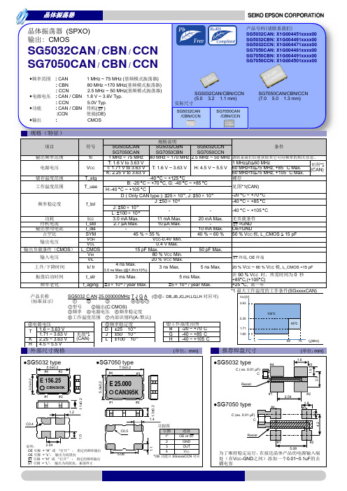
3 ns Max.
5 ns Max.
5 ms Max. 5 10-6 / year Max.
20 % VCC ~ 80 % VCC 极, L_CMOS =15 pF
在 90 % VCC 时,所需时间为 0 秒 +85C,(+105C) +25 C, 第一年
产品名称 (标准显示)
SG5032 C AN 25.000000MHz T J G A (⑤⑥: DB,JB,JG,JH,LG,LH 对应可)
5.0V Typ. 待机( ST ) 使能(OE)
CMOS
SG5032CAN/CBN/CCN (5.0 × 3.2 × 1.1 mm) 实际尺寸
SG5032CAN /CBN/CCN
SG7050CAN /CBN/CCN
SG7050CAN/CBN/CCN (7.0 × 5.0 × 1.3 mm)
规格(特征)
•频率范围
•电源电压 •功能 •输出
: CAN : CBN : CCN : CAN / CBN : CCN : CAN / CBN :CCN :
1 MHz ~ 75 MHz (基频模式振荡器) 80 MHz ~170 MHz(基频模式振荡器) 2.5 MHz ~ 50 MHz(基频模式振荡器)
1.8 V ~ 3.6V Typ.
VCC T_stg
T: 1.6 V to 3.63 V T: 1.71 V to 3.63 V T: 1.6 V ~ 3.63 V K: 2.25 V to 3.63 V
-40 C ~ +125 C
H: 4.5 V ~ 5.5 V
1 MHzf060 MHz
60 MHz<f075 MHz, +85 °C Max.
EIP-X5500 5500 ANSI 光度亮度高的项目器说明书

EIP-X55005,500 ANSI lumens bright with 80% uniformity and a 2200:1 contrast ratio.HDMI and Displayport Digital connectivity with HDCP compliance.Native XGA resolution. Compatible with inputs up-to UXGA and WSXGA+.Supports analog and digital video input in all color standards up-to patible with Crestron RoomView™ & AMX Device Discovery Technology.Vari-focal mid-range manual zoom and focus lens. Fixed image offset.Accepts composite, component, and S-Video in all major standards.Displays both 4:3 and 16:9 aspect ratios. Supports most HDTV resolutions.Built-in 3 Watt sound system. Closed Caption decoding (NTSC).Wired network monitoring and control. Digital zoom: 50% to 400%.3D Function (glasses not included).Top-accessed lamp for ease of maintenance.Custom warm-up screen. Auto input selection.Security bar. Kensington® MicroSaver® security slot. PIN lock.3 year projector warranty.Included Accessories:Optional Accessories:Brightness 5,500 ANSI Lumens Image Signal InputsContrast Ratio 2200:1 Computer 1 / Component (w/ optional adapter)Dsub15 x 1Illumination Uniformity 80% Computer 2 / Component (w/ optional adapter)Dsub15 x 1Resolution and Aspect Ratio XGA (1024 x 768), 4:3 Digital Video (w/ HDCP)HDMI x 25,500 ANSI Lumens / XGA / DLP®"Meeting Room" Series ProjectorEIP-X5500Quick Start Guide, Owner's Manual on CD-ROM, VGA Computer Input Cable (Dsub15 to Dsub15), 6.0 ft (1.8 m) Detachable Power Cord, Soft Carry Bag Remote Control (with 2 AAA Batteries)Replacement Lamp, Component Video Input Cable (Dsub15 to 3RCA), Ceiling Mount, Ceiling Post and PlateSpecifications: Model EIP-X5500Color Reproduction 1.07 billion colors Digital Video (w/ HDCP)DisplayPort x 1Projection Lamp 310 Watts UHP S-VideoS-Video x 1Estimated Lamp Life up-to 4,000 hours Composite Video RCA x 1Total Pixels 786,432 (1024x 768) x 1Audio Signal Inputs Imaging System 0.7" DMD™ DLP® chip x 1 Computer Audio MiniStereo x 1Scanning Frequency Auto: H Sync. 31-92 kHz, V Sync. 48-120 Hz Video Audio RCA x 2 (L/R)Pixel Clock up-to 150 MHz OutputsLens Attached (Vari-focal) Manual Zoom and FocusComputer Monitor (Analog)Dsub15 x 1Lens SpecsSpeed: f : 2.6-2.81; FL: 1.023-1.173 in (26.0-29.8 mm) Audio Output Variable, Stereo: MiniStereo x 1Lens Ratios Zoom Max:Min: 1.15:1 ; Throw:Width 1.8 - 2.1:1Amplifier Mono: 3 WattImage Diagonal 24-300 in (60.9-762 cm)Speaker1.4 in (3.7 cm) x 1 (Mono)Image Width 1.57-20 ft (0.48-6.1 m)Screen Trigger DC12V x 1Throw Distance 4.92-32.8 ft (1.5-10.0 m)3D3D Sync x 1Projector Elevation Adjustment (legs)up-to 10°Fan Noiseas low as 35 dBAMaximum Pitch up-to 15° Up or Down Cabinet Size (HxWxD) - excluding legs 4.75 x 13.3 x 10.5 in (12.0 x 33.8 x 26.7 cm)Fixed Image Offset 112.3% of Image Height up Weight8.4 lb (3.8 kg)Vertical Keystone Correction Digital: up-to 30° Up or Down Packaged Cabinet Size (HxWxD)7.7 x 17.9 x 19.6 in (19.5 x 45.4 x 49.7 cm)Image Orientation Normal, Reversed, Inverted Packaged Weight12.8 lb (5.8 kg)Local Control / Power Management Full Function / Auto Shutdown Operating Temperature41-95°F (5-35°C)Remote Control / Service Wireless (with laser pointer) x 1 / USB-B x 1Electrical Safety Compliance IEC / UL / cULRS-232 Control Dsub9 x 1Electromagnetic Compatibility FCC Class B, CE Mark LAN Port RJ45 x 1Power Requirements 100-240V AC, 50/60 HzComputer Input in Pixels up-to 1600x1200 (4:3), 1680x1050 (16:10)Power Consumption 0.5 W in Eco Standby mode, up-to 370WAnalog 4x3 Inputs UXGA, SXGA+, SXGA, XGA, SVGA, VGA, MAC Heatup-to 1,263 BTU/hrAnalog Wide Inputs WSXGA+, WXGA+, WXGA Security Facilities Security Bar, Kensington® Security SlotDigital 4x3 Inputs UXGA, SXGA+, SXGA, XGA, SVGA, VGA, MAC UPC4571194676600Digital Wide Inputs WSXGA+, WXGA+, WXGA User MaintenanceReplace LampVideo Formats NTSC / PAL / SECAM Limited Warranty: to the original end use customer only Video Input Analog 480i/p, 575i/p Projector *3 years / 6000 hoursVideo Input Digital 480p, 575p, 720p, 1080i/p Lamp*1 year ownership / 500 hours useImage Signal Resizing Smart Scaling Technology*(whichever occurs first)InCanada:310FirstSt.,Unit2,P.O.Box156,MidlandONL4R4K8.Tel:800-563-3454,Fax:800-567-4069,Email:***************Caution! Laser Radiation - Do not stare into beam. Max. Output: 1m Wave Length: 640 ~ 660 nm. Class ll Laser Product Lamp contains Mercury. Do not put in trash. Dispose of as Hazardous Waste, according to Local, State or Federal Laws.EIKI® is a registered trademark of Eiki International Inc. Kensington is a registered trademark of ACCO Brands Corporation.Specifications subject to change without notice. ©2013 Eiki International Inc. Issued Dec. 9, 2013EikiInternationalInc.,30251Esparanza,RanchoSantaMargarita,CA92688-2132.Tel:800-242-3454;Fax:800-457-3454,Email:************。
爱普生(EPSON)高精度晶体振荡器TG5032CCN TG5032SCN规格书
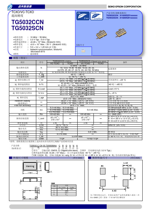
6.0 mA Max. / 8.0 mA Max.
5.0 mA Max.
8.0 mA Max. / 10.0 mA Max.
100 kΩ Min.
100 kΩ Min.
±5 ×10⁻⁶ ~ ±10 ×10-6
±5 ×10⁻⁶ ~ ±10 ×10-6
, +25 °C
-40 ºC ~ +85 ºC
Load ±10 %
): 40 MHz) 50 MHz) 40 MHz) 50 MHz)
±3.0 ×10⁻⁶ Max. (Stratum3 )
±0.01 × 10⁻⁶ Max.( +25 °C , 24
)
±0.04 × 10⁻⁶ Max.( +25 °C , 24
)
±4.6 × 10⁻⁶ Max.
5.0 mA Max. / 6.0 mA Max.
90 % VCC
:15pF
0
―― (
― ― ― ― ― TG5032 C CN 30.720000MHz C B G N N A
)― ― ― ― ― OE
(C: CMOS, S: Clipped sine wave)
―
(C: 3.3 V Typ.)
(B: ±0.28 × 10⁻⁶ Max.)
(G: -40 °C ~ +85 °C)
(N: ) VC (A: VC =any, D: VC =1.5 V, E: VC =1.65 V, H: VC =2.5 V, N: )
( :mm)
#4
#3
Marking
#4
(A极 ) ( :mm)
1.10 #3
3.20±0.2
#1
爱普生晶振TG-5501CA压控温补晶体振荡器规格书
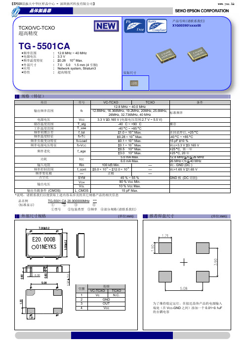
【EPSON晶振大中华区样品中心 - 深圳扬兴科技有限公司】
www.yxc.hk
推进环境管理体系 符合国际标准
在环境管理体系的运行方面,使用 ISO14001 国际环境标准,通过“计 划-实施-检查-验证(PDCA)的循环来实现持续改进。公司位于日本和 海外的主要制造基地已取得了 组织于 1996 年在全球化变暖、 臭 氧层破坏、以及全球毁林等环境问题日益严重的背景下提 出的环境管理国际标准。
追求高品质
Seiko Epson 为了向顾客提供高品质、卓越信赖性的产品、服务,迅 速着手通过 ISO 9000 系列资格认证的工作,其日本和海外工厂也在通 过 ISO 9001 认证。 同时, 也在通过大型汽车制造厂商要求规格的 ISO/TS 16949 认证。 ISO/TS16949 是一项国际标准,是在 ISO9001 的基础上增 加了对汽车工业的特殊要求部分。
④部分规格(请联系我们) (单位:mm)
外部尺寸规格
推荐焊盘尺寸
(单位:mm)
E20.000B ○01NEYKS
引脚 1 2 3 4
连接 VC-TCXO TCXO Vc N.C. GND OUT Vcc
为了维持稳定运行,在接近晶体产品的电源输入 端处(在 VCC-GND 之间)添加一个 0.01~0.1uF 的去耦电容
本材料中记载的品牌名称或产品名称是其所有人的商标或注册商标。
Seiko Epson Corporation
规格(特征)
VC-TCXO TCXO 12.8 MHz ~ 40.0 MHz 输出频率范围 f0 12.8MHz, 16.368MHz, 19.2MHz, 20MHz, 25.6MHz, 26MHz, 32.736MHz, 40 MHz 3.3 V 0.165 V (电源电压范围:2.7 V ~ 5.5 V) VCC 电源电压 T_stg 储存温度范围 -40 °C ~ +90 °C T_use 工作温度范围 -40 C ~ +85 C -6 f_tol 频率初期公差 1.0 10 Max. -6 频率温度特征 f0-TC 0.28 10 Max. -6 频率负载变动特征 f0-Load 0.1 10 Max. -6 频率电源电压特征 f0-VCC 0.1 10 Max. 0.5 × 10⁻⁶ Max. 频率老化 f_age 3.0 × 10⁻⁶ Max. 5.0 mA Max. 功耗 ICC 6.0 mA Max. 输入电阻 Rin 100 k Min. -6 -6 频率控制范围 f_cont 5.0 10 ~ 12.0 10 频率变化极 正极 占空比 SYM 45 % ~ 55 % 90 % Vcc Min. VOH 输出电压 10 % Vcc Max. VOL 输出负载条件 (CMOS) L_CMOS 15 pF Max. *说明:请联系我们以便获取上述内容未涉及的其它规格产品的相关信息 品名例 (标准显示) TG-5501 CA 20.000000MHz *** ① ② ③ ④ ①型号 ②包装类型 ③频率 项目 符号 条件 标准频率 裸存 在回流焊后, +25 C -40 C ~ +85 C 15 pF 10 % VCC=3.3 V 0.165 V +25 C, 第一年 +25 C, 20 年 12.8 MHz≦f0≦26 MHz 26 MHz<f0≦40 MHz VC - GND (DC ) VC=1.65 V 1.65 V GND 极 (DC 切割)
爱普生晶振RA8900CE实时时钟模块(I

DIVIDER
POWER CONTROLLER
INTERRUPTS CONTROLLER
FOUT CONTROLLER
BUS INTERFACE CIRCUIT
CLOCK and
CALENDR
TIMER REGISTER
ALARM REGISTER
CONTROL R EG ISTER
and SYSTEM
Min.
Typ.
Max.
VDD
2.5
3.0
5.5
V
VTEM
2.0
3.0
5.5
V
VCLK
1.6
3.0
5.5
V
TOPR UA
∆ f / f UB UC
-40
+25
+85
Ta = -40 ºC ~ +85 ºC
±3.4 ∗1
Ta = -40 ºC ~ +85 ºC Ta = -30 ºC ~ +70 ºC
CONTROL LER
• •UA •UB •UC
± 3.4 x 10⁻⁶ / -40 ºC ~ +85 ºC 商 ± 5.0 x 10⁻⁶ / -40 ºC ~ +85 ºC 商 ± 5.0 x 10⁻⁶ / -30 ºC ~ +70 ºC 商
9
器
13
器
13
器
• 32.768 kHz • FOUT •
Frequency temperature characteristics
10
5 32.768 kHz DTCXO
0
-5
-10
-15 Tuning fork X'tal
爱普生(EPSON)高精度晶体振荡器TG-5035CJ CG CE规格书
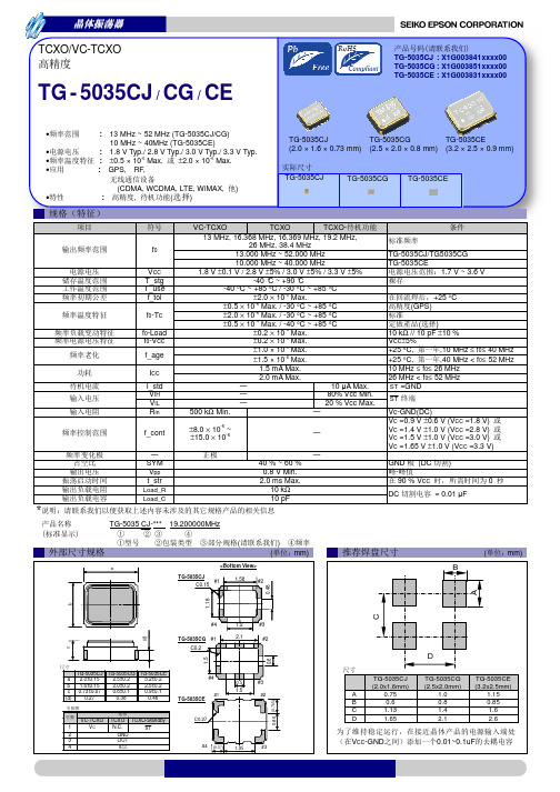
-40 °C ~ +90 °C
-40 °C ~ +85 °C / -30 °C ~ +85 °C ±2.0 × 10⁻⁶ Max.
±0.5 × 10⁻⁶ Max. / -30 °C ~ +85 °C ±2.0 × 10⁻⁶ Max. / -30 °C ~ +85 °C ±0.5 × 10⁻⁶ Max. / -40 °C ~ +85 °C
+25 °C,
,40 MHz < f0≤ 52 MHz
10 MHz ≤ f0≤ 26 MHz
26 MHz < f0≤ 52 MHz
ST =GND
ST
Vc-GND(DC)
VC =0.9 V ±0.6 V (VCC =1.8 V) VC =1.4 V ±1.0 V (VCC =2.8 V) VC =1.5 V ±1.0 V (VCC =3.0 V) VC =1.65 V ±1.0 V (VCC =3.3 V)
ISO/TS16949 是一项国际标准,是在 ISO9001 的基础上增 加了对汽车工业的特殊要求部分。
关于在目录内使用的记号
●无铅。
●符合欧盟 RoHS 指令。 欧盟 RoHS 指令免检的含铅产品。 (密封玻璃、高温熔化性焊料或其他材料中包含铅。)
●为汽车方面的应用,如汽车多媒体、车身电子、遥控无钥门锁等。
TG-5035CJ
TG-5035CG
TG-5035CE
•
: 1.8 V Typ./ 2.8 V Typ./ 3.0 V Typ./ 3.3 V Typ.
(2.0 × 1.6 × 0.73 mm) (2.5 × 2.0 × 0.8 mm) (3.2 × 2.5 × 0.9 mm)
爱普生晶振最小包装数量_标准包装规格
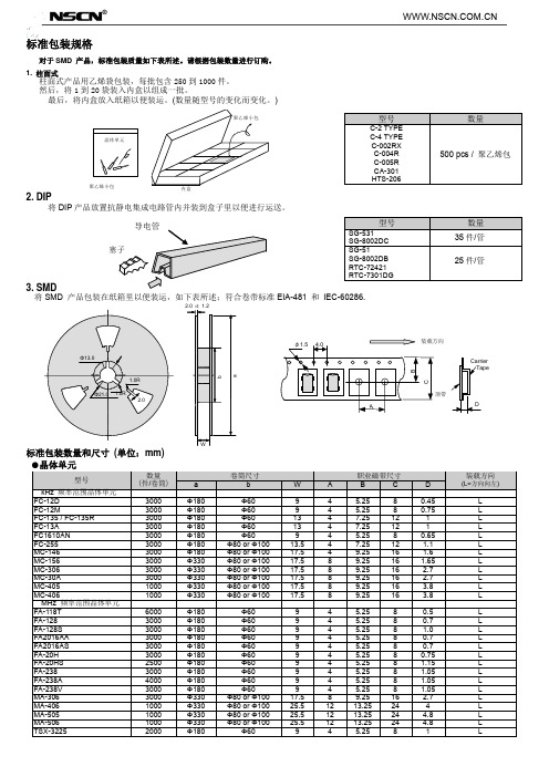
L L L L L L L L L L L L L L L L L L L L L L L L L L L
【南京南山:EPSON晶振代理证书编号14013】
●SAW 谐振器
型号 FS-335 FS-555 FS-585 NS-21R NS-32R 数量 (件/卷筒) 4000 4000 4000 3000 4000 1000 3000 3000 3000 1000 1000 2000 1000 2000 2000 2000 1000 1000 1000 1000 1000 1000 1000 1000 1000 1000 1000 1000 1000 1000 1000 1000 1000 1000 2000 1000 1000 1000 2000 1000 2000 3000 1000 2000 1000 1000 2000 1000 1000 1000 1000 2000 1000 1000 1000 1000 12000 2000 2000 12000 1000 1000 1000 1000 a Φ330 Φ330 Φ330 Φ180 Φ330 Φ254 Φ180 Φ180 Φ180 Φ330 Φ254 Φ180 Φ330 Φ180 Φ180 Φ180 Φ180 Φ330 Φ330 Φ254 Φ254 Φ180 Φ254 Φ180 Φ180 Φ180 Φ180 Φ180 Φ180 Φ180 Φ180 Φ180 Φ180 Φ254 Φ180 Φ330 Φ330 Φ254 Φ254 Φ254 Φ180 Φ180 Φ254 Φ254 Φ254 Φ330 Φ254 Φ330 Φ330 Φ254 Φ180 Φ180 Φ254 Φ180 Φ180 Φ180 Φ330 Φ180 Φ180 Φ330 Φ180 Φ180 Φ254 Φ180 卷筒尺寸 b Φ80 or Φ100 Φ80 or Φ100 Φ80 or Φ100 Φ60 Φ80 or Φ100 Φ100 Φ60 Φ60 Φ60 Φ80 or Φ100 Φ100 Φ60 Φ80 or Φ100 Φ60 Φ60 Φ60 Φ60 Φ80 or Φ100 Φ80 or Φ100 Φ100 Φ100 Φ60 Φ100 Φ60 Φ60 Φ60 Φ60 Φ60 Φ60 Φ60 Φ60 Φ60 Φ60 Φ100 Φ60 Φ80 or Φ100 Φ80 or Φ100 Φ100 Φ100 Φ100 Φ60 Φ60 Φ100 Φ100 Φ100 Φ80 or Φ100 Φ100 Φ80 Φ80 Φ100 Φ60 Φ60 Φ100 Φ60 Φ60 Φ60 Φ100 Φ60 Φ60 Φ100 Φ60 Φ60 Φ100 Φ60 W 13.5 13.5 13.5 9.0 13.5 17.5 9 9 13 17.5 17.5 13 17.5 13 9 9 13 25.5 17.5 17.5 17.5 17 17.5 13 13 13 17 17 17 17 13 17 13 17.5 9 25.5 17.5 17.5 13.4 17.5 9 9 17.5 13.4 17.5 17.5 13.4 25.5 25.5 17.5 13 9 17.5 17 13 17 9.4 9 9 9.4 13 13 17.5 17 A 8.0 8.0 8.0 4.0 8.0 8 4 4 4 8 8 4 8 4 4 4 8 12 8 8 8 8 8 8 8 8 8 8 8 8 8 8 8 8 4 12 8 8 8 8 4 4 8 8 8 8 8 12 12 8 8 4 8 8 8 8 4 4 4 4 8 8 8 8 职业磁带尺寸 B C 7.25 12.0 7.25 12.0 7.25 12.0 5.25 8.0 7.25 12.0 9.25 5.25 5.25 7.25 9.25 9.25 7.25 9.25 7.25 5.25 5.25 7.25 13.25 9.25 9.25 9.25 9.25 9.25 7.25 7.25 7.25 9.25 9.25 9.25 9.25 7.25 9.25 7.25 9.25 5.25 13.25 9.25 9.25 7.5 9.25 5.25 5.25 9.25 7.5 9.25 9.25 7.5 13.25 13.25 9.25 7.25 5.25 9.25 9.25 7.25 9.25 5.25 5.25 5.25 5.25 7.25 7.25 9.25 9.25 16 8 8 12 16 16 12 16 12 8 8 12 24 16 16 16 16 16 12 12 12 16 16 16 16 12 16 12 16 8 24 16 16 12 16 8 8 16 12 16 16 12 24 24 16 12 8 16 16 12 16 8 8 8 8 12 12 16 16
爱普生晶振OG2525CCN恒温OCXO振荡器规格书
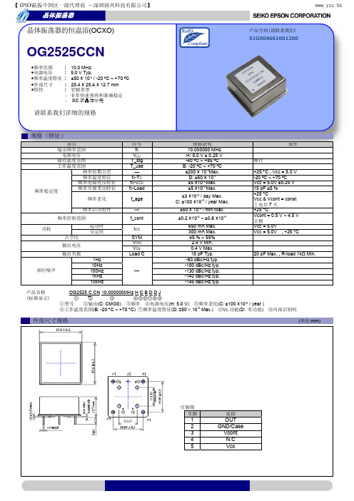
产品名称 (标准显示)
OG2525 C CN 10.000000MHz H C B D D J
①②
③
④⑤⑥⑦⑧⑨
①型号 ②输出(C: CMOS) ③频率 ④电源电压(H: 5.0 V) ⑤频率老化(C: ±100 ×10-9 / year )
⑥工作温度范围(B: -20 C ~ +70 C) ⑦频率温度特征(D: 50 10-9 Max.) ⑧VC 功能(D: 有功能)
条件
裸存
+25 C , Vcc = 5.0 V -20 ºC ~ +70 ºC Vcc = 5.0V ±0.25 V 15 pF ±5 % +25 °C Vcc & Vcont = const 上电后 7 天 +25 °C Vcont = 0.5 V ~ 4.5 V 正极 Vcc = 5.0V Vcc = 5.0V , +25 °C
ISO 14000 是国际标准化组织于 1996 年在全球化变暖、臭 氧层破坏、以及全球毁林等环境问题日益严重的背景下提
出的环境管理国际标准。
追求高品质
Seiko Epson 为了向顾客提供高品质、卓越信赖性的产品、服务,迅 速着手通过 ISO 9000 系列资格认证的工作,其日本和海外工厂也在通 过 ISO 9001 认证。同时,也在通过大型汽车制造厂商要求规格的 ISO/TS 16949 认证。
ISO/TS16949 是一项国际标准,是在 ISO9001 的基础上增 加了对汽车工业的特殊要求部分。
关于在目录内使用的记号
●无铅。
●符合欧盟 RoHS 指令。 欧盟 RoHS 指令免检的含铅产品。 (密封玻璃、高温熔化性焊料或其他材料中包含铅。)
爱普生(EPSON)晶体振荡器(可编程)SG-9101系列规格书
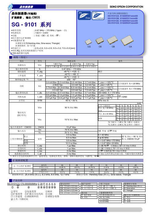
晶体振荡器
Spread Spectrum Specification Graph Spread Spectrum Profile fo : 170 MHz / Spread spectrum : ±2.0 % / Modulation frequency : 25.4 kHz Hershey-kiss Sine-wave Triangle
20 ① ③ ⑤ ⑦ ⑨ 20
10
0 -10
10 ⑪
Power (dBm)
0 -10 -20 -30 -40 -50 -60 -70 -80
①
③ ⑤ ⑦ ⑨ ⑪
Power (dBm)
-20 -30 -40 -50 -60 -70 -80 0 40 80 120 160 200 240 280 320 360 400
180 160 140 120 100 80 60 40 20 0 0 20 40 60
Cycle to Cycle Jitter Peak - Peak (ps)
180
Rise/Fall time = Default Rise/Fall time = Fast Rise/Fall time = Slow
裸存
3.7 mA Max. 3.2 mA Typ. 8.3 mA Max. 7.0 mA Typ. 3.7 mA Max. 2.5 µA Max. 1.1 µA Typ.
T_use = +105 C 无负载条件 f0 = 20 MHz T_use = +25 C T_use = +105 C 无负载条件 f0 = 170 MHz T_use = +25 C OE=GND, f0 = 170 MHz T_use = +105 C ST =GND T_use = +25 C 50% Vcc 级
- 1、下载文档前请自行甄别文档内容的完整性,平台不提供额外的编辑、内容补充、找答案等附加服务。
- 2、"仅部分预览"的文档,不可在线预览部分如存在完整性等问题,可反馈申请退款(可完整预览的文档不适用该条件!)。
- 3、如文档侵犯您的权益,请联系客服反馈,我们会尽快为您处理(人工客服工作时间:9:00-18:30)。
•
: Network synchronization, Stratum3,
Microwave BTS
•
:
(
器
TG-5500CA: X1G003561xxxxxx
TG-5501CA: X1G003901xxxxxx
TG-5500CA (10 )
TG-5500CA
TG-5501CA
TG-5501CA (4 )
未对任何专利或知识版权的许可权进行授权。 ·本材料中规格表中的数值大小通过数值线上的大小关系表示。 ·当出口此材料中描述的产品或技术时,你应该遵守相应的出口管制法律和法规,并按照这些法律和法规的要求执行。
请不要将产品(以及任何情况下提供任何的技术信息)用于开发或制造大规模杀伤性武器或其他军事用途。还要求,不要将产品提供给任何 将产品用于此类违禁用途的第三方。 ·此类产品是基于在一般电子机械内使用而设计开发的,如将产品应用于需要极高可靠性的特定用途,必须实现得到弊公司的事前许可。若 无许可弊公司将不负任何责任。
GND (DC )
10 % Vcc to 90 % Vcc ,
90 % VCC -
OE (
)
OE (
)
:15pF
0
TG-5500 CA 30.720000MHz ***
(
器
. #8 #7 #6
#9
#5
Marking
#10
#4
#1 #2 #3 7.00±0.2
0.80
2.54
1.00 #1 #2 #3
ISO/TS16949 是一项国际标准,是在 ISO9001 的基础上增 加了对汽车工业的特殊要求部分。
关于在目录内使用的记号
●无铅。
●符合欧盟 RoHS 指令。 欧盟 RoHS 指令免检的含铅产品。 (密封玻璃、高温熔化性焊料或其他材料中包含铅。)
●为汽车方面的应用,如汽车多媒体、车身电子、遥控无钥门锁等。
:2.7 V ~ 5.5 V)
-40 °C ~ +90 °C
-40 °C ~ +85 °C ±1.0 × 10⁻⁶ Max. ±0.28 × 10⁻⁶ Max.(12.8 MHz f0 50 MHz) ±0.25 × 10⁻⁶ Max.(12.8 MHz f0 50 MHz) : ±1.0 × 10⁻⁶ Max.(10 MHz f0 12.8 MHz) ±0.1 × 10⁻⁶ Max. ±0.1 × 10⁻⁶ Max. ±0.5 × 10⁻⁶ Max.
1.太空设备(人造卫星、火箭等) 2.运输车辆机器控制装置(汽车、飞机、火车、船舶等) 3.用于维持生命的医疗器械 4.海底中转设备 5.发电站控制机器 6.防灾防盗装置 7.交通设备 8.其他,用于与 1~7 具有同等可靠性的用途。
本材料中记载的品牌名称或产品名称是其所有人的商标或注册商标。
Seiko Epson Corporation
CMOS
Clipped sine wave
VC-TCXO
TCXO
VC-TCXO
TCXO
10 MHz ~ 50 MHz
10, 12.8, 15.36, 16.384, 19.44, 20, 24,
24.576, 25, 26, 27, 30.72, 40, 49.152, 50 MHz
3.3 V ±5%, 5.0 V ±5% (
●为汽车行驶安全方面的应用(引擎控制单元、气囊、电子稳定程序控制系统)。
注意事项
·本材料如有变更,恕不另行通知。量产设计时请确认最新信息。 ·未经 Seiko Epson 公司书面授权,禁止以任何形式或任何方式复制或者发布本材料中任何部分的信息内容。 ·本材料中的书面信息、应用电路、编程、使用等内容仅供参考。Seiko Epson 公司对第三方专利或版权的侵权行为不负有任何责任。本材料
a)
b)
c) d)
e)
Holdover stability
(
)
Free-run accuracy
/ *
f0
VCC T_stg T_use f_tol
f0-TC
f0-Load f0-VCC
f_age
-
-
ICC
Rin f_cont
SYM VOH VOL tr/ tf t_str VPP Load VIH VIL
±3.0 ×10⁻⁶ Max. (Stratum3 )
±0.01 × 10⁻⁶ Max.( +25 °C , 24
)
±0.04 × 10⁻⁶ Max.( +25 °C , 24
)
±4.6 × 10⁻⁶ Max. (12.8 MHz f0 50 MHz)
5.0 mA Max. / 6.0 mA Max.
TCXO/VC-TCXO
TG-5500CA / TG-5501CA
•
: 10 MHz ~ 50 MHz
•
: 3.3 V Typ. / 5.0 V Typ.
•
: ±0.28 × 10⁻⁶ Max. (Stratum3 )
•
: ±3.0 × 10⁻⁶ Max. / 20 (Stratum3 )
•
: 7.0 × 5.0 × 1.5 mm (10 始4 )
-
90 % Vcc Min.
-
10 % Vcc Max.
-
8.0 ns Max.
-
2.0 sec. Max.
-
0.8 V Min.
15 pF
10 kΩ//10 pF
70% VCC Min. 30% VCC Max.
, +25 °C
-40 °C ~ +85 °C
Load ±10 % VCC ±5 % +25 °C, +25 °C , 20
#3 #4
1.48
0.80
TG-5501CA→
1.27 1.27
2.88
2.88
( :mm)
←TG-5500CA
VCC-GND 0.01~0.1uF
推进环境管理体系 符合国际标准
在环境管理体系的运行方面,使用 ISO14001 国际环境标准,通过“计 划-实施-检查-验证(PDCA)的循环来实现持续改进。公司位于日本和 海外的主要制造基地已取得了 ISO14001 资格认证。
6.0 mA Max. / 8.0 mA Max.
5.0 mA Max.
8.0 mA Max. / 10.0 mA Max.
100 kΩ Min.
-
100 kΩ Min.
-
±5.0 × 10⁻⁶ ~ ±12.0 × 10⁻⁶
-
±5.0 × 10⁻⁶ ~ ±12.0 × 10⁻⁶
-
-
-
45 % ~ 55 %
ISO 14000 是国际标准化组织于 1996 年在全球化变暖、臭 氧层破坏、以及全球毁林等环境问题日益严重的背景下提
出的环境管理国际标准。
追求高品质
Seiko Epson 为了向顾客提供高品质、卓越信赖性的产品、服务,迅 速着手通过 ISO 9000 系列资格认证的工作,其日本和海外工厂也在通 过 ISO 9001 认证。同时,也在通过大型汽车制造厂商要求规格的 ISO/TS 16949 认证。
#10 #4
0.80
#9
OE OE
0.80
#8 #7
#5 #6 0.60
=H =L
2.54
1.50±0.2
5.00±0.2
←
1
2
0.80
3
4
5
6
7
8
9
10
1 2 3 4
TG-5500CA
VC-TCXO TCXO
N.C.
N.C.
N.C.
GND
OUT
N.C.
N.C.
OE
VCC VC
N.C.
→
TG-5501CA
VC-TCXO TCXO
VC
N.Cห้องสมุดไป่ตู้
GND
OUT
VCC
1.20 0.90 0.60
1.50±0.2
( (
) :mm)
#4
#3
5.00±0.2
Marking
#1 7.00±0.2 #2
5.08
#1
#2
#4
#3
1.51
1.00
3.88
3.88
1.27 1.27
#9 #8
#7
#6 #5
1.28
#10 #1
#2
10 48
a), b), c), d), e) 10 MHz f0 26 MHz (3.3 V / 5.0 V) 26 MHz f0 40 MHz (3.3 V / 5.0 V) 40 MHz f0 50 MHz (3.3 V / 5.0 V) VC - GND (DC ) VC=1.65 V ± 1.65 V (VCC=3.3 V) VC=2.5 V ± 2.0 V (VCC=5.0 V)
