(printed)All Controllers for the General H∞ Control Problem LMI Existence Conditions and State Spac
译林版高中英语学案选择性必修第二册精品课件 Unit 4 分层跟踪检测(二)

04 Unit 4 Living with technolog江1月卷) When was the last time you used a telephone box?I mean to make an actual phone call—not to shelter from the rain. Ages ago,right?The last time I used a phone box for its intended purpose was...2006.I was conducting auditions(试演) for my play in my tiny old shared house in London. Hoping to impress some talented actors to come and work for me for nothing,I spread some throws over the sofas and lit candles to make it seem a bit more “young professional”.
小学上册第十四次英语第4单元期末试卷

小学上册英语第4单元期末试卷英语试题一、综合题(本题有100小题,每小题1分,共100分.每小题不选、错误,均不给分)1.The scientist studies _____ (化学) processes in the lab.2. A _______ can help to measure the speed of sound in various mediums.3.What is the largest land animal?A. RhinocerosB. GiraffeC. ElephantD. Hippopotamus4.What do you call a small, round fruit?A. BerryB. MelonC. Stone fruitD. CitrusA5.What is the opposite of heavy?A. LightB. ThinC. FragileD. All of the aboveD6.The city of Kathmandu is the capital of _______.7.Plants produce ______ during photosynthesis.8.ta Stone unlocked the mysteries of ________ (古埃及文字). The Russ9.What do we call the lines that run north and south on a map?A. LatitudeB. LongitudeC. MeridianD. EquatorB10.The first successful heart transplant was performed in ________.11. A _______ is a process that involves chemical transformation.12.What is the name of the popular video game console produced by Nintendo?A. XboxB. PlayStationC. SwitchD. SegaC13. A ________ (鹦鹉) can talk and mimic sounds very well.14.She wears ________ (sneakers) for running.15.What is the name of our galaxy?A. AndromedaB. Milky WayC. WhirlpoolD. Triangulum16.Planting flowers in ______ can create beautiful landscapes. (在花坛中种植花卉可以创造美丽的景观。
Front End Controllers 7.1 产品说明书

Controllers FEC,Standard•Sturdy control rack requiring a minimum of space•Analogue inputs/outputs and Ethernet optional•Quick installation using the SAC sensor/actuator connector system•User-oriented software–programming the way you think or according to standard ElectroniccontrolsystemsFrontEndControllers 7.1Controllers FEC,StandardKeyfeaturesThe installation-saving controller The FEC Standard is not just a new mini controller.It shows that there is still room for innovation in mini controllers at the start of the new millennium.With its robust extruded aluminium housing,it demonstrates thatcompact design and toughness can go hand in hand.Its connector system is accessible from the front,ensuring no wastage of space within control cabinets.And the sensor/actuator connector system SAC,making its world premiere in this product,very largely replaces terminal strips in the I/O area.This means that control cabinets with FEC Standard have a decisive advantage:Up to 50%less space required,and up to 40%less time.Thanks to the integration of a high-speed counter into every CPU,this mini controller is well able to carry out counting and simple positioning operations.Additionally,the optional analogue inputs/outputs turn a smart mini controller into a smart process controller.The two serial interfaces in every CPU make the FEC Standard into a talented communicator which allows program-ming via one interface and operation and monitoring via the other,at the same time.The leading concept in communication today is Ethernet,the “network of networks”.This can of course be integrated intoFEC Standard as an option.After all,smart automation technologydemands smart network technology.With Ethernet and a web server,the FEC Standard paves the way for the visualisation technology of tomorrow:Controller surfing.E l e c t r o n i c c o n t r o l s y s t e m sF r o n t E n d C o n t r o l l e r s7.1Controllers FEC,StandardKey featuresHardwareThe FEC Standard has a clip for a top-hat rail and corner holes for bolt-mounting using a mounting plate.All connections are accessible from the front;there is no need for additional space for connections from above or below.Power supplyThe FEC Standard is poweredexclusively via 24V DC as per modern control cabinet technology.24V DC (+25%/-15%)power supply for the controller itself,24V DC (+/–25%)power supply for the input signals,positive switching,24V DC output signals 400mA,proof against short-circuits and low-resistance loads.The analogue inputs/outputs are 0(4)...20mA I/Os,12bitresolution.Serial interfacesEvery FEC Standard is equipped with two serial interfaces –COM and EXT.These are universal TTL interfaces with a maximum data transmission rate of 115kbits/s.Depending on requirements,the interfaces can be used as RS232c (SM14or SM15)or RS485(SM35)interfaces.Adapters should be ordered separately.The COM interface is generally used together with the SM14for program-ming,while the EXT interface can be used for an MMI device,a modem or other devices with a serial interface.Ethernet interfaceThe FEC Standard versions with an Ethernet interface incorporate an Ethernet 10BaseT interface with an RJ45connection and a data transmission rate of 10Mbits/s.A combined “Link/Active”LEDindicates the connection status.The FEC Standard supports datacommunication and programming/troubleshooting via the Ethernetinterface.ProgrammingThe FEC Standard is programmed using FST.FST is a unique programming language rich in tradition and very easy to use,allowing “programming the way you think”:IF...THEN...ELSEFST also supports STEP operation for sequence programming.FST can be used for programming via Ethernet;a web server is alsoavailable.E l e c t r o n i c c o n t r o l s y s t e m sF r o n t E n d C o n t r o l l e r s7.1Controllers FEC,StandardKey featuresThe sensor/actuatorconnectorTogether with the FEC Standard,we are introducing an innovative new installation concept,the sensor/actuator connector SAC.Thisconnector combines three functions in a very compact design:•Connection of inputs,outputs and power supply•Status signal by means of an LED •Replaces terminal strip for sensors andactuatorsThe three-wire version of theconnector has internally connected straps for 0V and 24V DC.This allows any sensor (up to 3wires)or actuator (up to the maximumpermissible output current)to be feddirectly to the connector.There is no need for a terminal strip for sensors and actuators.This allows space savings in control cabinets of up to 50%.The SAC uses a tension-spring contact system.This means no need for screw connections.Solid wires can simply be pushed into the connector,while in the case of finely-stranded wire,all that is necessary is to open the contact by pressing on the relevant pin and then introduce the wire.Cable end sleeves can be used if desired but are not essential.The tension-spring system and the fact that no terminal strip between the controller and sensors/actuator is required means that a time saving of up to 40%can be achieved during installation.The pin assignment for the I/O panel is simple and is always the same:Pin 1+24V DC Pin 2Bit 0Pin 3Bit 1Pin 4Bit 2Pin 5Bit 3Pin 6Bit 4Pin 7Bit 5Pin 8Bit 6Pin 9Bit 7Pin 100VThe power supply for the LEDs istaken from the signal pins in the connector.This means that the entire input assignment can be checked without acontroller.E l e c t r o n i c c o n t r o l s y s t e m sF r o n t E n d C o n t r o l l e r s7.1Controllers FEC,StandardKey featuresProgramming withFSTProgramming the way you think How do we describe a machine?“When a workpiece reaches here,this cylinder should advance.”How does the software interpretthis?Or does your machine work through a sequence step by step?“First,this cylinder must advance and stop the workpiece,and then the workpiece must be clamped,and thenfinally...”How,for example,can we sub-divide a task?Program 0:Organisation Program 1:Set-up program Program 2:AutomationprogramProgram 3:Fault monitoring Program 4:Manual operation ...Program 63:TroubleshootingprogramHow does one controller communicate with another?Every controller with Ethernet can send and receive data from every other controller within a network –no matter whether this data relates to inputs,outputs,flags or registers.Central programming of distributed controllersEvery controller within a network can be programmed from any desired network interface.A controller on the World Wide Web FST incorporates a web server –the Internet and the world of automationmeet.Programming just couldn’t beeasier.E l e c t r o n i c c o n t r o l s y s t e m sF r o n t E n d C o n t r o l l e r s7.1Controllers FEC,StandardProduct range overview The FECStandardE l e c t r o n i c c o n t r o l s y s t e m sF r o n t E n d C o n t r o l l e r s7.1Controllers FEC,StandardProduct range overviewThe principle of the FECStandard11235461In each case 16digital inputs,24V DC,positive-switching 2Optionally:3analogue inputs/1analogue output3In each case 8digital outputs 4Power supply5Rotary RUN/STOP switch 62serial interfaces,option ofEthernetE l e c t r o n i c c o n t r o l s y s t e m sF r o n t E n d C o n t r o l l e r s7.1Controllers FEC,StandardTechnical data General technical dataFEC-FC400FEC-FC440FEC-FC600FEC-FC640FEC-FC660Max.operating temperature0...55°C Max.transport and storage temperature –25...+70°CRel.humidity 0...95%(non condensing)Operating voltage 24V DC +25%/–15%Power consumption <5W Degree of protection IP20Degree of protection Degree of protection III.Power pack in accordance with IEC 742/EN60742/VDE0551/PELV with at least 4kV insulation resistance or switched-mode power supplies with safety isolation as defined by EN 60950/VDE 0805are required Certification C-TickI/O connection Tension spring connector EMC EN 61000-6-4Digital inputsFEC-FC400FEC-FC440FEC-FC600FEC-FC640FEC-FC660Number1632Number of above usable as high-speed inputs (max.2kHz)2Minimum pulse length for TRUE:250µs,Minimum pause length for FALSE:250µs Input voltage/current 24V DC,typical 5mA Nominal value for TRUE 15V DC min.Nominal value for FALSE 5V DC max.Input signal delay Typical 5msElectrical isolationYes,via optocoupler Permissible length of connecting cable Max.30mStatus display via LED Optional,in connectorAnalogue inputsFEC-FC400FEC-FC440FEC-FC600FEC-FC640FEC-FC660Number 03Signal range 0(4)...20mA Resolution12bit,±3LSB Conversion time10ms Permissible length of connecting cable Max.30mDigital outputsFEC-FC400FEC-FC440FEC-FC600FEC-FC640FEC-FC660Number 816ContactsTransistorCurrent/voltage 24V DC,max.400mA Short circuit proofYesProof against low-resistance loads Yes,up to 5W Overload-proof YesElectrical isolation Yes,via optocoupler Switching speedMax.1kHzElectrical isolation in groups Yes,in each case 1byte Maximum group current 3.2A Switching cyclesUnlimitedStatus display via LED Optional,in connectorAnalogue outputsFEC-FC400FEC-FC440FEC-FC600FEC-FC640FEC-FC660Number 01Signal range 0(4)...20mA Resolution12bit Conversion time 10ms Max.load resistance700ΩE l e c t r o n i c c o n t r o l s y s t e m sF r o n t E n d C o n t r o l l e r s7.1Controllers FEC,StandardTechnical dataRotary switchFEC-FC400FEC-FC440FEC-FC600FEC-FC640FEC-FC660 Number1Positions16STOP/RUN0=Stop1...F=RUNSerial interfaceFEC-FC400FEC-FC440FEC-FC600FEC-FC640FEC-FC660 Number2Connection RJ12plug socketFeatures Serial,asynchronous,TTL level,no electrical isolationUse as RS232c PS1-SM14or PS1-SM15requiredTerminal assignment SM14/15Transmit,receive,RTS,CTSUse as RS485PS1-SM35requiredUse as programming interface9600bits/s,8/N/1Use as universal interface:COM300...9600bits/s,7N1,7E1,7O1,8N1,8E1,8O1Use as universal interface:EXT300...115,000bits/s,7N1,7E1,7O1,8N1,8E1,8O1SAC connectorFEC-FC400FEC-FC440FEC-FC600FEC-FC640FEC-FC660 Number of connectors required44778 Insulating material PBT,colour blackTemperature range PS1-SAC10/SAC30:–20...+100°Cp gPS1-SAC11/SAC31:–20...+75°CFlammability class V-0Grid dimension 3.5mmConnector system Spring connectionInsulation-stripping length9...10mmClamping range0.05...1.5mm2Single-conductor H05(07)V-U0.20...1.5mm2Multi-stranded without cable end sleeves0.5...1.5mm2Multi-stranded with cable end sleeves inaccordance with DIN46228/10.5...1.5mm2Multi-stranded hot-dip galvanized0.05...0.2mm2Current rating for strap contacts16ACurrent rating for individual contacts2A(max.6A per contact,please note the admissible loads for distributor board and supply contacts)EthernetFEC-FC400FEC-FC440FEC-FC600FEC-FC640FEC-FC660 Number01011Bus interface IEEE802.3(10BaseT)Data transmission speed10Mbits/sConnector RJ45Supported protocols TCP/IP,EasyIP,httpOPC server upon requestDDE server Yes,for EasyIP ElectroniccontrolsystemsFrontEndControllers 7.1Controllers FEC,StandardTechnical data ProgrammingFSTProgramming languages Version 4.02:statement list(with version 3.2:statement list and ladder diagram in German and English)Working languageGerman and English Number of programs and tasks per project64(0...63)Permissible input addresses0 (255)addressable as bits or words Permissible output addresses 0 (255)addressable as bits or words Number of flags10,000(0...9999),addressable as bits or wordsNumber of timers and counters 256(0...255)in each case,with 1status bit,1setpoint and 1actual value Number of registers (words)0 (255)addressable as words Programming interfaceRS232or Ethernet Number of different operations >28Subroutine Up to 200different subroutines per project C/C++Yes,for modules and drivers File handling Yes RS232c Yes ABG Yes FEDYesWeb server Yes (FST from version 4)RemanenceFlag words 0...255Register 0 (126)Timer and counter preselects and counter words 0...127PasswordPerformance1.6ms/1k instructions approx.E l e c t r o n i c c o n t r o l s y s t e m sF r o n t E n d C o n t r o l l e r s7.1Controllers FEC,Standard Technical dataType L1L2FEC-FC4…132.1114.2FEC-FC6…174.7156.8Ordering data–The FEC Standard with FST programmingDesignation Features Part No.TypeIPC controller16I/8O183862FEC-FC400-FST 16I/8O,Ethernet185205FEC-FC440-FST32I/16O191449FEC-FC600-FST32I/16O,Ethernet191450FEC-FC640-FST32I/16O,3/1analogue I/Os,Ethernet197157FEC-FC660-FST ElectroniccontrolsystemsFrontEndControllers 7.12006/0920064/7.1-2320062006/094/7.1-24Controllers FEC,StandardTechnical dataOrdering data –Connectors for the FEC Standard Designation Features Part No.TypePlug 1-row,no LED,tension-spring system 197159PS1-SAC10-10POL Plug 1-row,with LED,tension-spring system 197160PS1-SAC11-10POL+LED Plug 3-row,no LED,tension-spring system 197161PS1-SAC30-30POL Plug3-row,with LED,tension-spring system197162PS1-SAC31-30POL+LEDOrdering data –Cables for the FEC Standard Designation Features Part No.TypeProgramming cable RS232adapter for programming from PC,complete with neutral modem cable 188935PS1-SM14-RS232Converter RS232adapter for connection of any desired devices with a serial interface,with top-hat-rail clip,no neutral modem or RS232cable 192681PS1-SM15-RS232Converter RS485adapter,with top-hat-rail clip 193390PS1-SM35-RS485CableNeutral modem cable160786PS1-ZK11-NULLMODEM-1,5M Earthing setEarthing set for earthing of cable screening via the H-rail526683FEC-ZE30Ordering data –Display and operating units Designation Features Part No.Type Operator unitDisplay and operating unit,LCD with 4lines,20characters each,illuminatedbackground,4function keys,real-time clock and expansion interface,e.g.Ethernet533531FED-50Operator unit Display and operating unit,LCD with 4lines,20characters each,illuminated background,12function keys,numeric keypad,real-time clock and expansion interface,e.g.Ethernet533532FED-90Fieldbus interface Ethernet interface module for FED 533533FEDZ-IET Programming cable Programming cable for FED533534FEDZ-PC Cable Connecting cable FEC (RJ12,COM and EXT)to FED189432FEC-KBG6Ordering data –Software and manuals for the FEC Standard Designation Features Part No.TypeProgramming softwareFST software version4.X on CD,manuals on CD191440PS1-FST2-CD-WIN g g FST software version 4.1on CD with manual DIN A5in German 537927P .SW-FST4-CD-DE FST software version 4.1on CD with manual DIN A5in English 537928P .SW-FST4-CD-EN ManualSystem manual FEC Standard,German 525368P .BE-FEC-S-SYS-DE System manual FEC Standard,English525369P .BE-FEC-S-SYS-ENE l e c t r o n i c c o n t r o l s y s t e m sF r o n t E n d C o n t r o l l e r s7.1。
电力系统内多个FACTS设备的协调优化控制

电力系统内多个FACTS设备的协调优化控制FACTS设备一般有多个输入量和输出量。
有时候单个输入量会影响一系列输出量,或多个输入量共同影响输出量。
这种交互影响是否会弱化控制效果甚至使系统失稳,即是否属于负交互影响,是FACTS控制关注的重点。
另外,为了更好地发挥FACTS的作用,装置通常安装在关键的电气节点,其影响和波及面较大,设备间难免也会产生负交互影响。
电力系统的负交互影响常见于电力系统稳定器(Power System Stabilizers,PSS)之间。
随着FACTS研究的深入,目前也发现了诸多存在于FACTS控制器间负交互影响的实例。
例如,静止同步补偿器(static synchronous compensator,STATCOM)的直流电压控制器与交流电压控制器之间存在负交互影响,会导致它们联合运行的失败。
统一潮流控制器(Unified Power Flow Controller,UPFC)是目前FACTS设备中功能最强的控制器,可独立控制母线电压幅值、相角及无功功率,但已有研究表明,UPFC多个控制回路间可能存在负交互影响,从而破坏系统稳定性。
静止无功补偿器(Static Var Compensator,SVC)能有效地保持电压稳定,是目前应用最广泛的FACTS设备。
但多台SVC运行时它们之间产生的模态交互可能使系统运行恶化。
研究发现SVC和可控串联电容补偿(Thyristor Controlled Series Capacitor,TCSC)之间的交互影响可能会导致系统产生高频振荡。
协调控制的关键是如何处理好各控制器之间的相互作用。
根据对控制器之间相互作用处理方式的不同,协调方法可以分为分散控制协调方法、基于合作的协调控制方法、非线性协调控制方法以及综合各种方法优点的分级控制方法等几大类。
1 分散协调控制方法分散控制是大系统理论的一个重要分支,它的研究内容是:在大系统中限定各局部控制器只反馈本地可测的状态变量或输出变量,通过设计这些局部控制器,使系统的总体性能达到一定的指标。
Native Instruments MASCHINE MK3 用户手册说明书

The information in this document is subject to change without notice and does not represent a commitment on the part of Native Instruments GmbH. The software described by this docu-ment is subject to a License Agreement and may not be copied to other media. No part of this publication may be copied, reproduced or otherwise transmitted or recorded, for any purpose, without prior written permission by Native Instruments GmbH, hereinafter referred to as Native Instruments.“Native Instruments”, “NI” and associated logos are (registered) trademarks of Native Instru-ments GmbH.ASIO, VST, HALion and Cubase are registered trademarks of Steinberg Media Technologies GmbH.All other product and company names are trademarks™ or registered® trademarks of their re-spective holders. Use of them does not imply any affiliation with or endorsement by them.Document authored by: David Gover and Nico Sidi.Software version: 2.8 (02/2019)Hardware version: MASCHINE MK3Special thanks to the Beta Test Team, who were invaluable not just in tracking down bugs, but in making this a better product.NATIVE INSTRUMENTS GmbH Schlesische Str. 29-30D-10997 Berlin Germanywww.native-instruments.de NATIVE INSTRUMENTS North America, Inc. 6725 Sunset Boulevard5th FloorLos Angeles, CA 90028USANATIVE INSTRUMENTS K.K.YO Building 3FJingumae 6-7-15, Shibuya-ku, Tokyo 150-0001Japanwww.native-instruments.co.jp NATIVE INSTRUMENTS UK Limited 18 Phipp StreetLondon EC2A 4NUUKNATIVE INSTRUMENTS FRANCE SARL 113 Rue Saint-Maur75011 ParisFrance SHENZHEN NATIVE INSTRUMENTS COMPANY Limited 5F, Shenzhen Zimao Center111 Taizi Road, Nanshan District, Shenzhen, GuangdongChina© NATIVE INSTRUMENTS GmbH, 2019. All rights reserved.Table of Contents1Welcome to MASCHINE (25)1.1MASCHINE Documentation (26)1.2Document Conventions (27)1.3New Features in MASCHINE 2.8 (29)1.4New Features in MASCHINE 2.7.10 (31)1.5New Features in MASCHINE 2.7.8 (31)1.6New Features in MASCHINE 2.7.7 (32)1.7New Features in MASCHINE 2.7.4 (33)1.8New Features in MASCHINE 2.7.3 (36)2Quick Reference (38)2.1Using Your Controller (38)2.1.1Controller Modes and Mode Pinning (38)2.1.2Controlling the Software Views from Your Controller (40)2.2MASCHINE Project Overview (43)2.2.1Sound Content (44)2.2.2Arrangement (45)2.3MASCHINE Hardware Overview (48)2.3.1MASCHINE Hardware Overview (48)2.3.1.1Control Section (50)2.3.1.2Edit Section (53)2.3.1.3Performance Section (54)2.3.1.4Group Section (56)2.3.1.5Transport Section (56)2.3.1.6Pad Section (58)2.3.1.7Rear Panel (63)2.4MASCHINE Software Overview (65)2.4.1Header (66)2.4.2Browser (68)2.4.3Arranger (70)2.4.4Control Area (73)2.4.5Pattern Editor (74)3Basic Concepts (76)3.1Important Names and Concepts (76)3.2Adjusting the MASCHINE User Interface (79)3.2.1Adjusting the Size of the Interface (79)3.2.2Switching between Ideas View and Song View (80)3.2.3Showing/Hiding the Browser (81)3.2.4Showing/Hiding the Control Lane (81)3.3Common Operations (82)3.3.1Using the 4-Directional Push Encoder (82)3.3.2Pinning a Mode on the Controller (83)3.3.3Adjusting Volume, Swing, and Tempo (84)3.3.4Undo/Redo (87)3.3.5List Overlay for Selectors (89)3.3.6Zoom and Scroll Overlays (90)3.3.7Focusing on a Group or a Sound (91)3.3.8Switching Between the Master, Group, and Sound Level (96)3.3.9Navigating Channel Properties, Plug-ins, and Parameter Pages in the Control Area.973.3.9.1Extended Navigate Mode on Your Controller (102)3.3.10Navigating the Software Using the Controller (105)3.3.11Using Two or More Hardware Controllers (106)3.3.12Touch Auto-Write Option (108)3.4Native Kontrol Standard (110)3.5Stand-Alone and Plug-in Mode (111)3.5.1Differences between Stand-Alone and Plug-in Mode (112)3.5.2Switching Instances (113)3.5.3Controlling Various Instances with Different Controllers (114)3.6Host Integration (114)3.6.1Setting up Host Integration (115)3.6.1.1Setting up Ableton Live (macOS) (115)3.6.1.2Setting up Ableton Live (Windows) (116)3.6.1.3Setting up Apple Logic Pro X (116)3.6.2Integration with Ableton Live (117)3.6.3Integration with Apple Logic Pro X (119)3.7Preferences (120)3.7.1Preferences – General Page (121)3.7.2Preferences – Audio Page (126)3.7.3Preferences – MIDI Page (130)3.7.4Preferences – Default Page (133)3.7.5Preferences – Library Page (137)3.7.6Preferences – Plug-ins Page (145)3.7.7Preferences – Hardware Page (150)3.7.8Preferences – Colors Page (154)3.8Integrating MASCHINE into a MIDI Setup (156)3.8.1Connecting External MIDI Equipment (156)3.8.2Sync to External MIDI Clock (157)3.8.3Send MIDI Clock (158)3.9Syncing MASCHINE using Ableton Link (159)3.9.1Connecting to a Network (159)3.9.2Joining and Leaving a Link Session (159)3.10Using a Pedal with the MASCHINE Controller (160)3.11File Management on the MASCHINE Controller (161)4Browser (163)4.1Browser Basics (163)4.1.1The MASCHINE Library (163)4.1.2Browsing the Library vs. Browsing Your Hard Disks (164)4.2Searching and Loading Files from the Library (165)4.2.1Overview of the Library Pane (165)4.2.2Selecting or Loading a Product and Selecting a Bank from the Browser (170)4.2.2.1[MK3] Browsing by Product Category Using the Controller (174)4.2.2.2[MK3] Browsing by Product Vendor Using the Controller (174)4.2.3Selecting a Product Category, a Product, a Bank, and a Sub-Bank (175)4.2.3.1Selecting a Product Category, a Product, a Bank, and a Sub-Bank on theController (179)4.2.4Selecting a File Type (180)4.2.5Choosing Between Factory and User Content (181)4.2.6Selecting Type and Character Tags (182)4.2.7List and Tag Overlays in the Browser (186)4.2.8Performing a Text Search (188)4.2.9Loading a File from the Result List (188)4.3Additional Browsing Tools (193)4.3.1Loading the Selected Files Automatically (193)4.3.2Auditioning Instrument Presets (195)4.3.3Auditioning Samples (196)4.3.4Loading Groups with Patterns (197)4.3.5Loading Groups with Routing (198)4.3.6Displaying File Information (198)4.4Using Favorites in the Browser (199)4.5Editing the Files’ Tags and Properties (203)4.5.1Attribute Editor Basics (203)4.5.2The Bank Page (205)4.5.3The Types and Characters Pages (205)4.5.4The Properties Page (208)4.6Loading and Importing Files from Your File System (209)4.6.1Overview of the FILES Pane (209)4.6.2Using Favorites (211)4.6.3Using the Location Bar (212)4.6.4Navigating to Recent Locations (213)4.6.5Using the Result List (214)4.6.6Importing Files to the MASCHINE Library (217)4.7Locating Missing Samples (219)4.8Using Quick Browse (221)5Managing Sounds, Groups, and Your Project (225)5.1Overview of the Sounds, Groups, and Master (225)5.1.1The Sound, Group, and Master Channels (226)5.1.2Similarities and Differences in Handling Sounds and Groups (227)5.1.3Selecting Multiple Sounds or Groups (228)5.2Managing Sounds (233)5.2.1Loading Sounds (235)5.2.2Pre-listening to Sounds (236)5.2.3Renaming Sound Slots (237)5.2.4Changing the Sound’s Color (237)5.2.5Saving Sounds (239)5.2.6Copying and Pasting Sounds (241)5.2.7Moving Sounds (244)5.2.8Resetting Sound Slots (245)5.3Managing Groups (247)5.3.1Creating Groups (248)5.3.2Loading Groups (249)5.3.3Renaming Groups (251)5.3.4Changing the Group’s Color (251)5.3.5Saving Groups (253)5.3.6Copying and Pasting Groups (255)5.3.7Reordering Groups (258)5.3.8Deleting Groups (259)5.4Exporting MASCHINE Objects and Audio (260)5.4.1Saving a Group with its Samples (261)5.4.2Saving a Project with its Samples (262)5.4.3Exporting Audio (264)5.5Importing Third-Party File Formats (270)5.5.1Loading REX Files into Sound Slots (270)5.5.2Importing MPC Programs to Groups (271)6Playing on the Controller (275)6.1Adjusting the Pads (275)6.1.1The Pad View in the Software (275)6.1.2Choosing a Pad Input Mode (277)6.1.3Adjusting the Base Key (280)6.1.4Using Choke Groups (282)6.1.5Using Link Groups (284)6.2Adjusting the Key, Choke, and Link Parameters for Multiple Sounds (286)6.3Playing Tools (287)6.3.1Mute and Solo (288)6.3.2Choke All Notes (292)6.3.3Groove (293)6.3.4Level, Tempo, Tune, and Groove Shortcuts on Your Controller (295)6.3.5Tap Tempo (299)6.4Performance Features (300)6.4.1Overview of the Perform Features (300)6.4.2Selecting a Scale and Creating Chords (303)6.4.3Scale and Chord Parameters (303)6.4.4Creating Arpeggios and Repeated Notes (316)6.4.5Swing on Note Repeat / Arp Output (321)6.5Using Lock Snapshots (322)6.5.1Creating a Lock Snapshot (322)6.5.2Using Extended Lock (323)6.5.3Updating a Lock Snapshot (323)6.5.4Recalling a Lock Snapshot (324)6.5.5Morphing Between Lock Snapshots (324)6.5.6Deleting a Lock Snapshot (325)6.5.7Triggering Lock Snapshots via MIDI (326)6.6Using the Smart Strip (327)6.6.1Pitch Mode (328)6.6.2Modulation Mode (328)6.6.3Perform Mode (328)6.6.4Notes Mode (329)7Working with Plug-ins (330)7.1Plug-in Overview (330)7.1.1Plug-in Basics (330)7.1.2First Plug-in Slot of Sounds: Choosing the Sound’s Role (334)7.1.3Loading, Removing, and Replacing a Plug-in (335)7.1.3.1Browser Plug-in Slot Selection (341)7.1.4Adjusting the Plug-in Parameters (344)7.1.5Bypassing Plug-in Slots (344)7.1.6Using Side-Chain (346)7.1.7Moving Plug-ins (346)7.1.8Alternative: the Plug-in Strip (348)7.1.9Saving and Recalling Plug-in Presets (348)7.1.9.1Saving Plug-in Presets (349)7.1.9.2Recalling Plug-in Presets (350)7.1.9.3Removing a Default Plug-in Preset (351)7.2The Sampler Plug-in (352)7.2.1Page 1: Voice Settings / Engine (354)7.2.2Page 2: Pitch / Envelope (356)7.2.3Page 3: FX / Filter (359)7.2.4Page 4: Modulation (361)7.2.5Page 5: LFO (363)7.2.6Page 6: Velocity / Modwheel (365)7.3Using Native Instruments and External Plug-ins (367)7.3.1Opening/Closing Plug-in Windows (367)7.3.2Using the VST/AU Plug-in Parameters (370)7.3.3Setting Up Your Own Parameter Pages (371)7.3.4Using VST/AU Plug-in Presets (376)7.3.5Multiple-Output Plug-ins and Multitimbral Plug-ins (378)8Using the Audio Plug-in (380)8.1Loading a Loop into the Audio Plug-in (384)8.2Editing Audio in the Audio Plug-in (385)8.3Using Loop Mode (386)8.4Using Gate Mode (388)9Using the Drumsynths (390)9.1Drumsynths – General Handling (391)9.1.1Engines: Many Different Drums per Drumsynth (391)9.1.2Common Parameter Organization (391)9.1.3Shared Parameters (394)9.1.4Various Velocity Responses (394)9.1.5Pitch Range, Tuning, and MIDI Notes (394)9.2The Kicks (395)9.2.1Kick – Sub (397)9.2.2Kick – Tronic (399)9.2.3Kick – Dusty (402)9.2.4Kick – Grit (403)9.2.5Kick – Rasper (406)9.2.6Kick – Snappy (407)9.2.7Kick – Bold (409)9.2.8Kick – Maple (411)9.2.9Kick – Push (412)9.3The Snares (414)9.3.1Snare – Volt (416)9.3.2Snare – Bit (418)9.3.3Snare – Pow (420)9.3.4Snare – Sharp (421)9.3.5Snare – Airy (423)9.3.6Snare – Vintage (425)9.3.7Snare – Chrome (427)9.3.8Snare – Iron (429)9.3.9Snare – Clap (431)9.3.10Snare – Breaker (433)9.4The Hi-hats (435)9.4.1Hi-hat – Silver (436)9.4.2Hi-hat – Circuit (438)9.4.3Hi-hat – Memory (440)9.4.4Hi-hat – Hybrid (442)9.4.5Creating a Pattern with Closed and Open Hi-hats (444)9.5The Toms (445)9.5.1Tom – Tronic (447)9.5.2Tom – Fractal (449)9.5.3Tom – Floor (453)9.5.4Tom – High (455)9.6The Percussions (456)9.6.1Percussion – Fractal (458)9.6.2Percussion – Kettle (461)9.6.3Percussion – Shaker (463)9.7The Cymbals (467)9.7.1Cymbal – Crash (469)9.7.2Cymbal – Ride (471)10Using the Bass Synth (474)10.1Bass Synth – General Handling (475)10.1.1Parameter Organization (475)10.1.2Bass Synth Parameters (477)11Working with Patterns (479)11.1Pattern Basics (479)11.1.1Pattern Editor Overview (480)11.1.2Navigating the Event Area (486)11.1.3Following the Playback Position in the Pattern (488)11.1.4Jumping to Another Playback Position in the Pattern (489)11.1.5Group View and Keyboard View (491)11.1.6Adjusting the Arrange Grid and the Pattern Length (493)11.1.7Adjusting the Step Grid and the Nudge Grid (497)11.2Recording Patterns in Real Time (501)11.2.1Recording Your Patterns Live (501)11.2.2The Record Prepare Mode (504)11.2.3Using the Metronome (505)11.2.4Recording with Count-in (506)11.2.5Quantizing while Recording (508)11.3Recording Patterns with the Step Sequencer (508)11.3.1Step Mode Basics (508)11.3.2Editing Events in Step Mode (511)11.3.3Recording Modulation in Step Mode (513)11.4Editing Events (514)11.4.1Editing Events with the Mouse: an Overview (514)11.4.2Creating Events/Notes (517)11.4.3Selecting Events/Notes (518)11.4.4Editing Selected Events/Notes (526)11.4.5Deleting Events/Notes (532)11.4.6Cut, Copy, and Paste Events/Notes (535)11.4.7Quantizing Events/Notes (538)11.4.8Quantization While Playing (540)11.4.9Doubling a Pattern (541)11.4.10Adding Variation to Patterns (541)11.5Recording and Editing Modulation (546)11.5.1Which Parameters Are Modulatable? (547)11.5.2Recording Modulation (548)11.5.3Creating and Editing Modulation in the Control Lane (550)11.6Creating MIDI Tracks from Scratch in MASCHINE (555)11.7Managing Patterns (557)11.7.1The Pattern Manager and Pattern Mode (558)11.7.2Selecting Patterns and Pattern Banks (560)11.7.3Creating Patterns (563)11.7.4Deleting Patterns (565)11.7.5Creating and Deleting Pattern Banks (566)11.7.6Naming Patterns (568)11.7.7Changing the Pattern’s Color (570)11.7.8Duplicating, Copying, and Pasting Patterns (571)11.7.9Moving Patterns (574)11.7.10Adjusting Pattern Length in Fine Increments (575)11.8Importing/Exporting Audio and MIDI to/from Patterns (576)11.8.1Exporting Audio from Patterns (576)11.8.2Exporting MIDI from Patterns (577)11.8.3Importing MIDI to Patterns (580)12Audio Routing, Remote Control, and Macro Controls (589)12.1Audio Routing in MASCHINE (590)12.1.1Sending External Audio to Sounds (591)12.1.2Configuring the Main Output of Sounds and Groups (596)12.1.3Setting Up Auxiliary Outputs for Sounds and Groups (601)12.1.4Configuring the Master and Cue Outputs of MASCHINE (605)12.1.5Mono Audio Inputs (610)12.1.5.1Configuring External Inputs for Sounds in Mix View (611)12.2Using MIDI Control and Host Automation (614)12.2.1Triggering Sounds via MIDI Notes (615)12.2.2Triggering Scenes via MIDI (622)12.2.3Controlling Parameters via MIDI and Host Automation (623)12.2.4Selecting VST/AU Plug-in Presets via MIDI Program Change (631)12.2.5Sending MIDI from Sounds (632)12.3Creating Custom Sets of Parameters with the Macro Controls (636)12.3.1Macro Control Overview (637)12.3.2Assigning Macro Controls Using the Software (638)12.3.3Assigning Macro Controls Using the Controller (644)13Controlling Your Mix (646)13.1Mix View Basics (646)13.1.1Switching between Arrange View and Mix View (646)13.1.2Mix View Elements (647)13.2The Mixer (649)13.2.1Displaying Groups vs. Displaying Sounds (650)13.2.2Adjusting the Mixer Layout (652)13.2.3Selecting Channel Strips (653)13.2.4Managing Your Channels in the Mixer (654)13.2.5Adjusting Settings in the Channel Strips (656)13.2.6Using the Cue Bus (660)13.3The Plug-in Chain (662)13.4The Plug-in Strip (663)13.4.1The Plug-in Header (665)13.4.2Panels for Drumsynths and Internal Effects (667)13.4.3Panel for the Sampler (668)13.4.4Custom Panels for Native Instruments Plug-ins (671)13.4.5Undocking a Plug-in Panel (Native Instruments and External Plug-ins Only) (675)13.5Controlling Your Mix from the Controller (677)13.5.1Navigating Your Channels in Mix Mode (678)13.5.2Adjusting the Level and Pan in Mix Mode (679)13.5.3Mute and Solo in Mix Mode (680)13.5.4Plug-in Icons in Mix Mode (680)14Using Effects (681)14.1Applying Effects to a Sound, a Group or the Master (681)14.1.1Adding an Effect (681)14.1.2Other Operations on Effects (690)14.1.3Using the Side-Chain Input (692)14.2Applying Effects to External Audio (695)14.2.1Step 1: Configure MASCHINE Audio Inputs (695)14.2.2Step 2: Set up a Sound to Receive the External Input (698)14.2.3Step 3: Load an Effect to Process an Input (700)14.3Creating a Send Effect (701)14.3.1Step 1: Set Up a Sound or Group as Send Effect (702)14.3.2Step 2: Route Audio to the Send Effect (706)14.3.3 A Few Notes on Send Effects (708)14.4Creating Multi-Effects (709)15Effect Reference (712)15.1Dynamics (713)15.1.1Compressor (713)15.1.2Gate (717)15.1.3Transient Master (721)15.1.4Limiter (723)15.1.5Maximizer (727)15.2Filtering Effects (730)15.2.1EQ (730)15.2.2Filter (733)15.2.3Cabinet (737)15.3Modulation Effects (738)15.3.1Chorus (738)15.3.2Flanger (740)15.3.3FM (742)15.3.4Freq Shifter (743)15.3.5Phaser (745)15.4Spatial and Reverb Effects (747)15.4.1Ice (747)15.4.2Metaverb (749)15.4.3Reflex (750)15.4.4Reverb (Legacy) (752)15.4.5Reverb (754)15.4.5.1Reverb Room (754)15.4.5.2Reverb Hall (757)15.4.5.3Plate Reverb (760)15.5Delays (762)15.5.1Beat Delay (762)15.5.2Grain Delay (765)15.5.3Grain Stretch (767)15.5.4Resochord (769)15.6Distortion Effects (771)15.6.1Distortion (771)15.6.2Lofi (774)15.6.3Saturator (775)15.7Perform FX (779)15.7.1Filter (780)15.7.2Flanger (782)15.7.3Burst Echo (785)15.7.4Reso Echo (787)15.7.5Ring (790)15.7.6Stutter (792)15.7.7Tremolo (795)15.7.8Scratcher (798)16Working with the Arranger (801)16.1Arranger Basics (801)16.1.1Navigating Song View (804)16.1.2Following the Playback Position in Your Project (806)16.1.3Performing with Scenes and Sections using the Pads (807)16.2Using Ideas View (811)16.2.1Scene Overview (811)16.2.2Creating Scenes (813)16.2.3Assigning and Removing Patterns (813)16.2.4Selecting Scenes (817)16.2.5Deleting Scenes (818)16.2.6Creating and Deleting Scene Banks (820)16.2.7Clearing Scenes (820)16.2.8Duplicating Scenes (821)16.2.9Reordering Scenes (822)16.2.10Making Scenes Unique (824)16.2.11Appending Scenes to Arrangement (825)16.2.12Naming Scenes (826)16.2.13Changing the Color of a Scene (827)16.3Using Song View (828)16.3.1Section Management Overview (828)16.3.2Creating Sections (833)16.3.3Assigning a Scene to a Section (834)16.3.4Selecting Sections and Section Banks (835)16.3.5Reorganizing Sections (839)16.3.6Adjusting the Length of a Section (840)16.3.6.1Adjusting the Length of a Section Using the Software (841)16.3.6.2Adjusting the Length of a Section Using the Controller (843)16.3.7Clearing a Pattern in Song View (843)16.3.8Duplicating Sections (844)16.3.8.1Making Sections Unique (845)16.3.9Removing Sections (846)16.3.10Renaming Scenes (848)16.3.11Clearing Sections (849)16.3.12Creating and Deleting Section Banks (850)16.3.13Working with Patterns in Song view (850)16.3.13.1Creating a Pattern in Song View (850)16.3.13.2Selecting a Pattern in Song View (850)16.3.13.3Clearing a Pattern in Song View (851)16.3.13.4Renaming a Pattern in Song View (851)16.3.13.5Coloring a Pattern in Song View (851)16.3.13.6Removing a Pattern in Song View (852)16.3.13.7Duplicating a Pattern in Song View (852)16.3.14Enabling Auto Length (852)16.3.15Looping (853)16.3.15.1Setting the Loop Range in the Software (854)16.4Playing with Sections (855)16.4.1Jumping to another Playback Position in Your Project (855)16.5Triggering Sections or Scenes via MIDI (856)16.6The Arrange Grid (858)16.7Quick Grid (860)17Sampling and Sample Mapping (862)17.1Opening the Sample Editor (862)17.2Recording Audio (863)17.2.1Opening the Record Page (863)17.2.2Selecting the Source and the Recording Mode (865)17.2.3Arming, Starting, and Stopping the Recording (868)17.2.5Using the Footswitch for Recording Audio (871)17.2.6Checking Your Recordings (872)17.2.7Location and Name of Your Recorded Samples (876)17.3Editing a Sample (876)17.3.1Using the Edit Page (877)17.3.2Audio Editing Functions (882)17.4Slicing a Sample (890)17.4.1Opening the Slice Page (891)17.4.2Adjusting the Slicing Settings (893)17.4.3Live Slicing (898)17.4.3.1Live Slicing Using the Controller (898)17.4.3.2Delete All Slices (899)17.4.4Manually Adjusting Your Slices (899)17.4.5Applying the Slicing (906)17.5Mapping Samples to Zones (912)17.5.1Opening the Zone Page (912)17.5.2Zone Page Overview (913)17.5.3Selecting and Managing Zones in the Zone List (915)17.5.4Selecting and Editing Zones in the Map View (920)17.5.5Editing Zones in the Sample View (924)17.5.6Adjusting the Zone Settings (927)17.5.7Adding Samples to the Sample Map (934)18Appendix: Tips for Playing Live (937)18.1Preparations (937)18.1.1Focus on the Hardware (937)18.1.2Customize the Pads of the Hardware (937)18.1.3Check Your CPU Power Before Playing (937)18.1.4Name and Color Your Groups, Patterns, Sounds and Scenes (938)18.1.5Consider Using a Limiter on Your Master (938)18.1.6Hook Up Your Other Gear and Sync It with MIDI Clock (938)18.1.7Improvise (938)18.2Basic Techniques (938)18.2.1Use Mute and Solo (938)18.2.2Use Scene Mode and Tweak the Loop Range (939)18.2.3Create Variations of Your Drum Patterns in the Step Sequencer (939)18.2.4Use Note Repeat (939)18.2.5Set Up Your Own Multi-effect Groups and Automate Them (939)18.3Special Tricks (940)18.3.1Changing Pattern Length for Variation (940)18.3.2Using Loops to Cycle Through Samples (940)18.3.3Using Loops to Cycle Through Samples (940)18.3.4Load Long Audio Files and Play with the Start Point (940)19Troubleshooting (941)19.1Knowledge Base (941)19.2Technical Support (941)19.3Registration Support (942)19.4User Forum (942)20Glossary (943)Index (951)1Welcome to MASCHINEThank you for buying MASCHINE!MASCHINE is a groove production studio that implements the familiar working style of classi-cal groove boxes along with the advantages of a computer based system. MASCHINE is ideal for making music live, as well as in the studio. It’s the hands-on aspect of a dedicated instru-ment, the MASCHINE hardware controller, united with the advanced editing features of the MASCHINE software.Creating beats is often not very intuitive with a computer, but using the MASCHINE hardware controller to do it makes it easy and fun. You can tap in freely with the pads or use Note Re-peat to jam along. Alternatively, build your beats using the step sequencer just as in classic drum machines.Patterns can be intuitively combined and rearranged on the fly to form larger ideas. You can try out several different versions of a song without ever having to stop the music.Since you can integrate it into any sequencer that supports VST, AU, or AAX plug-ins, you can reap the benefits in almost any software setup, or use it as a stand-alone application. You can sample your own material, slice loops and rearrange them easily.However, MASCHINE is a lot more than an ordinary groovebox or sampler: it comes with an inspiring 7-gigabyte library, and a sophisticated, yet easy to use tag-based Browser to give you instant access to the sounds you are looking for.What’s more, MASCHINE provides lots of options for manipulating your sounds via internal ef-fects and other sound-shaping possibilities. You can also control external MIDI hardware and 3rd-party software with the MASCHINE hardware controller, while customizing the functions of the pads, knobs and buttons according to your needs utilizing the included Controller Editor application. We hope you enjoy this fantastic instrument as much as we do. Now let’s get go-ing!—The MASCHINE team at Native Instruments.MASCHINE Documentation1.1MASCHINE DocumentationNative Instruments provide many information sources regarding MASCHINE. The main docu-ments should be read in the following sequence:1.MASCHINE Getting Started: This document provides a practical approach to MASCHINE viaa set of tutorials covering easy and more advanced tasks in order to help you familiarizeyourself with MASCHINE.2.MASCHINE Manual (this document): The MASCHINE Manual provides you with a compre-hensive description of all MASCHINE software and hardware features.Additional documentation sources provide you with details on more specific topics:▪Controller Editor Manual: Besides using your MASCHINE hardware controller together withits dedicated MASCHINE software, you can also use it as a powerful and highly versatileMIDI controller to pilot any other MIDI-capable application or device. This is made possibleby the Controller Editor software, an application that allows you to precisely define all MIDIassignments for your MASCHINE controller. The Controller Editor was installed during theMASCHINE installation procedure. For more information on this, please refer to the Con-troller Editor Manual available as a PDF file via the Help menu of Controller Editor.▪Online Support Videos: You can find a number of support videos on The Official Native In-struments Support Channel under the following URL: https:///NIsupport-EN. We recommend that you follow along with these instructions while the respective ap-plication is running on your computer.Other Online Resources:If you are experiencing problems related to your Native Instruments product that the supplied documentation does not cover, there are several ways of getting help:▪Knowledge Base▪User Forum▪Technical Support▪Registration SupportYou will find more information on these subjects in the chapter Troubleshooting.1.2Document ConventionsThis section introduces you to the signage and text highlighting used in this manual. This man-ual uses particular formatting to point out special facts and to warn you of potential issues. The icons introducing these notes let you see what kind of information is to be expected:This document uses particular formatting to point out special facts and to warn you of poten-tial issues. The icons introducing the following notes let you see what kind of information can be expected:Furthermore, the following formatting is used:▪Text appearing in (drop-down) menus (such as Open…, Save as… etc.) in the software and paths to locations on your hard disk or other storage devices is printed in italics.▪Text appearing elsewhere (labels of buttons, controls, text next to checkboxes etc.) in the software is printed in blue. Whenever you see this formatting applied, you will find the same text appearing somewhere on the screen.▪Text appearing on the displays of the controller is printed in light grey. Whenever you see this formatting applied, you will find the same text on a controller display.▪Text appearing on labels of the hardware controller is printed in orange. Whenever you see this formatting applied, you will find the same text on the controller.▪Important names and concepts are printed in bold.▪References to keys on your computer’s keyboard you’ll find put in square brackets (e.g.,“Press [Shift] + [Enter]”).►Single instructions are introduced by this play button type arrow.→Results of actions are introduced by this smaller arrow.Naming ConventionThroughout the documentation we will refer to MASCHINE controller (or just controller) as the hardware controller and MASCHINE software as the software installed on your computer.The term “effect” will sometimes be abbreviated as “FX” when referring to elements in the MA-SCHINE software and hardware. These terms have the same meaning.Button Combinations and Shortcuts on Your ControllerMost instructions will use the “+” sign to indicate buttons (or buttons and pads) that must be pressed simultaneously, starting with the button indicated first. E.g., an instruction such as:“Press SHIFT + PLAY”means:1.Press and hold SHIFT.2.While holding SHIFT, press PLAY and release it.3.Release SHIFT.Unlabeled Buttons on the ControllerThe buttons and knobs above and below the displays on your MASCHINE controller do not have labels.。
Magtrol HD系列磁滞动力计说明书

HD SERIES HD SERIESHYSTERESIS DYNAMOMETERSMAGTROL offers 3 types of dynamometer brakes to absorb load: Hysteresis (HD Series), Eddy-Current (WB Series) and Magnetic Powder (PB Series). Each type of Dynamometer has advantages and limitations and choosing the correct one will depend largely on the type of testing to be performed. With over 50 standard models to choose from, Magtrol Sales professionals are readily available to assist in selecting the proper Dynamometer to meet your testing needs.FEATURES▪16 Standard Models with Maximum Torque from2.5 oz·in to 500 lb·in (18 mN·m to 56.5 N·m)▪14 High Speed Models Available▪Hysteresis Braking System: provides precise torqueloading independent of shaft speed▪Motor Testing: from no load to locked rotor▪Standard Torque Units: SI(English & Metric available upon request)▪Accuracy: ± 0.25 % (full scale)▪Air Flow Sensor: For protection against overheatingand operator error▪Base Plates: available in long or short versions▪Custom Dynamometers: for special torque andspeed requirements▪Easy CalibrationDESCRIPTIONHysteresis Brake Dynamometers (HD Series) are versatile and ideal for testing in the low to medium power range (maximum 14 kW intermittent duty). With a Hysteresis Braking system, the Dynamometers do not require speed to create torque, and there-fore can provide a full motor ramp from free-run to locked rotor. Brake cooling is provided by convection (no external source), by compressed air or by dedicated blower, depending on the model. All Magtrol Hysteresis Dynamometers have accuracy ratings of ± 0.25 % (full scale) depending on size and system configuration. To better integrate dynamometers into systems, Magtrol offers both long and short base plates. The shorter base plate facili-tates easier motor mounting when used with T-slot tables and Magtrol Adjustable Motor Fixtures, where as the long base plates are better suited for table top testing.APPLICATIONSMagtrol motor test systems can be found in test labs, at inspec-tion stations, and on the manufacturing floors of most of the world’s leading manufacturers, users and certifiers of small to medium sized electric, pneumatic and hydraulic motors, as well as internal combustion engines. Magtrol supplies motor test systems for a wide array of industries including: Appliance, Auto-motive, Aviation, Computer, HVAC, Lawn and Garden, Medical and Dental, Electric Motor, Office Equipment and Power Tools.Fig. 1: HD-715 | Hysteresis DynamometerMagtrol’s Hysteresis Dynamometers cover a wide range of Torque, Speed and Mechanical Power ratings. To select the appropriate size Dynamometer for your motor testing needs, you will need to determine the Maximum Torque, Speed and Power applied to the Dynamometer.MAXIMUM TORQUEThe Magtrol Hysteresis Absorption Dynamometer will develop braking torque at any speed point, including low speed and stall conditions ("0" rpm). It is important to consider all torque points that are to be tested, not only rated torque, but also locked rotor and breakdown torque. Dynamometer selection should initially be based on the maximum torque requirement, subject to determining the maximum power requirements. MAXIMUM SPEEDThis rating is to be considered independent of torque and power requirements, and is the maximum speed at which the Dynamometer can be safely run under free-run or lightly loaded conditions. It is not to be considered as the maximum speed at which full braking torque can be applied.MAXIMUM POWER RATINGSThese ratings represent the maximum capability of the Dyna-mometer Braking System to absorb and dissipate heat gener-ated when applying a braking load to the motor under test. The power absorbed and the heat generated by the Dynamometer is a function of the Torque (T) applied to the motor under test, and the resulting Speed (n) of the motor. This is expressed in these Power (P) formulas:The Dynamometer’s ability to dissipate heat is a function of how long a load will be applied. For this reason, the maximum power ratings given are based on continuous operation under load, as well as a maximum of 5 minutes under load.To safely dissipate heat and avoid Dynamometer failure, the maximum power rating is the most important consideration in selecting a Dynamometer.Magtrol Hysteresis Dynamometers absorb power with a unique Hysteresis Braking Systemwhich provides frictionless torque loading independent of shaft speed. The HysteresisBrake provides torque by the use of two basic components - a reticulated pole structureand a specialty steel rotor/shaft assembly - fitted together but not in physical contact.Until the pole structure is energized, the drag cup can spin freely on its shaft bear-ings. When a magnetizing force from the field coil is applied to the pole structure,the air gap becomes a flux field and the rotor is magnetically restrained, providinga braking action between the pole structure and rotor.Magtrol’s M-TEST Software isa state-of-the-art motor testingprogram for Windows®-baseddata acquisition. Used with aMagtrol DSP 7010 Dynamom-eter Controller, Magtrol M-TESTSoftware provides the control ofany Magtrol Dynamometer and runs test sequences in a manner best suited to the overall accuracy and efficiency of the Magtrol Motor T est System. The data that is generated by Magtrol’s Motor T esting Software can be stored, dis-played and printed in tabular or graphic formats, and can be easily imported into a spreadsheet.Written in LabVIEW™, M-TEST has the flexibility to test a majority of motor types in a variety of ways. Because of LabVIEW’s versatility, obtaining data from other sources (e.g. thermocouples), controlling motor power and providing audio/visual indicators is relatively easy. Magtrol’s M-TEST Software is ideal for simulating loads, cycling the unit under test and motor ramping. Because it is easy to gather data and duplicate tests, the software is ideal for use in engineering labs. T ests can be programmed to run on their own and saved for future use allowing for valuable time savings in production testing and incoming/outgoing inspection.SI: P[W] = T[N·m] × n[min-1]× (1.047 x 10-1) English: P[W] = T[lb·in] × n[rpm]× (1.183 x 10⁻²) Metric: P[W] = T[kg·cm] × n[rpm]× (1.027 x 10⁻²) All of Magtrol’s controllers, readouts and software calculate horsepower as defined by 1 [hp] = 550 [lb·ft /s].Using this definition:P[hp] = P[W] / 745.7Pole StructureBearingAir GapOPEN LOOP SYSTEMSMagtrol offers both open loop manual test systems and PC-based closed loop test systems. A typical open loop system will consist of a Dynamometer and a Magtrol DSP 7010 Dynamom-eter Controller in Open-Loop configuration. A Magtrol Single or Three-Phase Power Analyzer, which allows for the capturing of volts, amps, watts and power factor, can be included as an option. An open loop system is often used for quick pass / fail testing on the production line or at incoming inspection. Magtrol’s DSP 7010 Dynamometer Controller provides pass / fail testing as a standard feature.CLOSED LOOP SYSTEMSIn a closed loop motor test system, data is collected on a PC using Magtrol’s M-TEST Software, DSP 7010 Dynamometer Controller, and requisite interface cards and cables. Magtrol’s DSP 7010 Dynamometer Controllers compute and display mechanical power (in horsepower or watts) in addition to torque and speed. A Single or Three Phase Power Analyzer, a required component in a test system measuring motor efficiency, can be integrated into this system as well as Magtrol’s Temperature Testing Hardware.MODEL 7500Computer witha) All -5C dynamometers are 5 Volt Output.Please, contact our sales representative for 6C (English units), 7C (Metric units) or 8C (SI units) specifications.b) Operating at the continuous power rating for periods of up to 4 hours isacceptable. However, operating for extended periods at high temperatures will result in premature component and bearing failure. Limiting the length of the cycle and the component temperatures will guard against premature failure. Where continuous duty is desired for longer time intervals, compo-nent temperatures should be maintained less than 100°C; monitoring the outside brake surface temperature is a sufficient reference.c) Requires air cooling provided by user. Regulator and filter package isprovided as standard d) Blower is includede) The maximum speed will depend on what type of keyway (if any) is usedon the shaft. Unless specified, the dynamometer shaft will be made withouta keyway.ELECTRICAL POWERHD-100 / 400 / 500 SERIES WITH LONG BASE PLATEb) Shaft Flats are not available on high speed models.a) These dimensions represent the distance between mounting holes. Thereare four (4) mounting holes on each base plate.HD-100 / 400 / 500 SERIES WITH SHORT BASE PLATEb) Shaft Flats are not available on high speed models.a) These dimensions represent the distance between mounting holes. Thereare four (4) mounting holes on each base plate.a) These dimensions represent the distance between mounting holes. Thereare four (4) mounting holes on each base plate.b) Shaft Flats are not available on high speed models.are four (4) mounting holes on each base plate.a) These dimensions represent the distance between mounting holes. There are four (4) mounting holes on each base plate.BLOWER POWER▪Models HD-710, HD-715 & HD-810 include the BL-001 blower.▪Models HD-815 include the BL-002 blower. ▪Model HD-825 uses two BL-002 blowers for cooling its two brake sets.On / Off Switch120/240 V AC / 50/60 HzAllow approximately 6 in to 8 in (152 mm to 203 mm) between rear of dynamom-eter base plate and blower for connection hardware. Required hardware is sup-plied with the dynamometer.BL-002 Blower has two filter elements.HD 106 & HD 106 HSHD-100 & HD 100 HSHD 400 & HD 400 HSHD 500 & HD 500 HS30 00040 00050 00060 000Maximum Rated Speed for standard versionMaximum Rated Speed for High Speed version m )0.0000.0020.0040.0060.0100.0120.0140.0160.018010 00020 00030 00040 00050 00060 000S P E E D (r p m )TORQUE (N·m )0.000.010.020.030.040.050.060.070.085 00010 00020 00025 00030 00035 00040 00045 00015 000S P E E D (r p m )TORQUE (N·m )HD 510 & HD 510 HSHD 505 & HD 505 HSHD 515 & HD 515 HSHD 700 & HD 700 HSHD 710 & HD 710 HSHD 705 & HD 705 HS5 00010 00020 00025 00030 00015 00035 00040 00045 0000.10.00.20.30.40.50.60.70.8S P E E D (r p m )TORQUE (N·m )0.000.250.500.751.001.251.505 00010 00020 00025 00030 00015 00035 00040 00045 000S P E E D (r p m )TORQUE (N·m )0.000.250.500.751.001.251.505 00010 00020 00025 00030 00015 00035 00040 00045 000S P E E D (r p m )TORQUE (N·m )0.00.5 1.0 1.5 2.0 2.5 3.05 00010 00020 00025 00030 00015 00035 00040 000S P E E D (r p m )TORQUE (N·m )0.00.51.01.52.02.53.0 05 00010 00020 00025 00030 00035 00040 00015 000S P E E D (r p m )0.01.02.03.04.05.06.05 00010 00020 00025 00030 00015 00035 00040 000S P E E D (r p m )HD 715 & HD 715 HSHD 800HD 805HD 810 & HD 810 HSHD 815 & HD 815 HSHD 825 & HD 825 HS0.01.02.03.04.05.06.0 05 00010 00020 00025 00030 00040 00035 00015 000S P E E D (r p m )TORQUE (N·m)0.02.0 4.0 6.08.012.010.014.04 000 2 0006 00010 00012 00014 0008 000S P E E D (r p m )TORQUE (N·m)0.05.010.015.020.025.02 0004 0006 0008 00010 00012 00014 000S P E E D (r p m )TORQUE (N·m )0.02.0 4.08.06.010.012.014.04 000 2 0006 00010 00012 00014 00016 0008 000S P E E D (r p m )TORQUE (N·m )0.05.010.015.020.025.04 000 2 0006 00010 00012 00014 00016 0008 000S P E E D (r p m )TORQUE (N·m )0.010.020.030.040.050.02 0004 0006 0008 00012 00010 000S P E E D (r p m )TORQUE (N·m )The power absorption curves represent the maximum power (heat) that the dynamometer can dissipate over time.HD SERIESHD Series Hysteresis Dynamometers can be incorporated into a Customized Motor Test System (CMTS )These PC based, turn-key systems arecustom designed and built to meet specific user requirements.Various devices such as dynamometer con-trollers, power analyzers or other customized devices can be easily integrated into a 19" rack system (in an external cabinet or directly in the table).These systems integrate specific software (such as M-TEST) to facilitate the measure-ment process.ENCODER OPTIONS FOR LOW SPEED TESTINGFor low speed motors, such as gear motors with maximum speeds of less than 200 rpm, Magtrol offers additional encoder options that allow for increased resolution of the speed signal.T-SLOT BASE PLATETo accommodate Magtrol AMF-3 Adjustable Motor Fixtures, a grooved base plate with three M12 T-slots, one centered and two 250 mm apart, is available on all HD-8XX series dynamometers.MECHANICAL CUSTOMISATIONSMagtrol is highly experienced and qualified in the customization of its products. We can provide custom-ized base plates, riser blocks and shaft modifications.Our specialized salesmen and technicians are at your service to help you find the best configuration for your project.a) In case of special design the 4 last digits will be specific; please contactour sales representative b) Please contact our sales representative regarding long base plate c) PPR means Pulse Per RevolutionExample: HD Series Dynamometer, model 106, supply in 240 V A C, shortbase plate, 60-PPR encoder and standard version would be ordered as follows: HD-106-5C2-0100HD Series Dynamometer, model 805, supply in 120 V A C, long base plate with T-slot, 6000-PPR encoder and high speed version would be ordered as follows: HD-805-5C1-024HCABLE ASSEMBLYa) Other lenght available on requestDynamometer TableBlowerAdjustable Motor FixtureMotor Under TestHeavy-duty Equipment RackFully customizable (19" rack standards)Control screen(optional touchscreen)Command Panel(allows easy access to the main functions)Connection Panel To connect external devices or options spe-cific to the test bench (temperature probe,...)DSP 7010 Series Dynamometer Controller MODEL 7500 SeriesPower AnalyzerFull Computer (inlcuding rack mounted keyboard,...)Free rack mounted spacefor third-party equipment (e.g. power supply, measuringinstrument, etc...)© 2023 MAGTROL | Due to continual product development, Magtrol reserves the right to modify specifications without forewarning.Page 14 / 14DATASHEETI E S - U S 06 / 2023HD SERIESSYSTEM OPTIONS AND ACCESSORIESDSP 7010 - DYNAMOMETER CONTROLLERSMagtrol’s MODEL DSP 7010 Series Dynamometer Controller employs state-of-the-art Digital Signal Processing Technol-ogy to provide superior motor testing capabilities. Designed for use with any Magtrol Hysteresis, Eddy-Current or Powder Dynamometer, Magtrol In-Line Torque Transducer or auxiliary instrumentation, the DSP 7010 can provide complete PC control via the USB or IEEE-488 interface. With up to 500 readings per second, the DSP 7010 is ideally suited for both the test lab and the production line.WB & PB SERIES - DYNAMOMETERThe WB Series (eddy current) and PB Series (magnetic powder) dyna-mometers are particularly suitable for demanding applications requiring low (PB) to high (WB up to 65 000 rpm) speeds. The PB brakes will develop their nominal torque atstandstill, while the WBbrakes develop a braking torque proportional to the speed and their maximum torque is reached at nominal speed. The brake is cooled by water circulating in the stator. As a result, these dynamometers are able to dissipate high continuous loads (up to 140 kW). The WB and PB dynamometers incorporate a torque measuring system which has an accuracy of ± 0.3 % to ± 0.5 % at full scale.MODEL 7500 - POWER ANALYZERSThe Magtrol MODEL 7500 Power Analyzer is an easy-to-use instrument ideal for numerous power measurement applications. From DC to 80 kHz, the MODEL 7500 measures volts, amps, watts, volt-amps, frequency, crest factor, Vpeak, Apeak and power factor in one convenient display. They may be used either as stand-alone instruments or in conjunction with any Magtrol Hysteresis, Eddy-Current or Powder Brake Dynamometer; any Magtrol Dynamometer Controller and M-TEST Software for more demanding motor test applications.AMF SERIES - MOTOR FIXTURESPositioning and alignment have a great influence on the measured parameters (friction torque). MAG-TROL strongly recommends a sup-port specifically dedicated to the products to be tested to ensure the best positioning tolerances in X-Y , and its repeatability.Alternatively, Magtrol AMF Series (Adjustable Motor Fixtures) can be used. These extremely versatile fixtures can accommodate motors up to 101 m m (4") in diameter. It enables easy motor centering during testing, but does not have centering references.TAB SERIES - DYNAMOMETER TABLESTest from a stationary position or move a dynamometer to alternate testing stations with ease with Magtrol’s Dynamometer Table. The stand is designed from lightweight aluminum with casters for smooth mobility, and is sturdy enough to support even the heaviest of Magtrol dynamometers. The design can be retrofitted to any Magtrol dynamometer and is easily reconfigured for added versatility.Fig. 7: DSP 7011 | Programmable Dynamometer ControllersFig. 8: 1 PB 115 | Powder DynamometerFig. 9: MODEL 7510 | Power AnalyzersFig. 10: T AB Series | Dynamometer Tables。
[lua]lua中匹配字符串小数
![[lua]lua中匹配字符串小数](https://img.taocdn.com/s3/m/6961780f91c69ec3d5bbfd0a79563c1ec5dad7b6.png)
[lua]lua中匹配字符串⼩数如何从字符串中正确匹配出⼩数(带符号)字符串?使⽤ string.gmatch说明见官⽅⽂档,摘录如下:string.gmatch (s, pattern)Returns an iterator function that, each time it is called, returns the next captures from pattern over string s.If pattern specifies no captures, then the whole match is produced in each call.As an example, the following loops = "hello world from Lua"for w in string.gmatch(s, "%a+") doprint(w)endwill iterate over all the words from string s, printing one per line. The next example collects all pairs key=value from the given string into a table:t = {}s = "from=world, to=Lua"for k, v in string.gmatch(s, "(%w+)=(%w+)") dot[k] = vend例⼦:local numberT = {}local paramStr = '[2.04523,-3.4901,12030.39458,20]'for k in string.gmatch(paramStr, '(%-?%d+%.*%d*)') do table.insert(numberT, tonumber(k))endfor _, v in ipairs(numberT) do print('type(v)='..type(v), 'v='..v)end--运⾏结果为:type(v)=number v=2.04523type(v)=number v=-3.4901type(v)=number v=12030.39458type(v)=number v=20--上述中的模式串带⼩括号(),表⽰⼀个匹配结果中需要符合我们所定义的匹配⽅式(%-?%d+%.*%d*)--总结:碰到lua中的特殊字符(⽐如 . / % - + ? 等等)需要先⽤%作为转义字符,--⽐如上⾯的模式串 (%-?%d+%.*%d*) 分为 %-? %d+ %.* %d*-- %-? %是转义了后⾯跟着的- ⽽?表⽰匹配0或1个,亦即匹配0或1个--- %d+ %d表⽰匹配数字跟着+号表⽰匹配1或者多个数字-- %.* %是转义了后⾯跟着的. 跟着的*号表⽰匹配0到多个.-- %d* 表⽰匹配0或者多个数字。
关闭转换IQ传输器(ATC-800)自动转换开关技术数据说明书
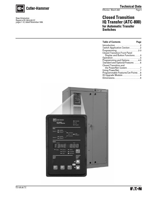
Closed Transition IQ Transfer (ATC-800)for Automatic Transfer SwitchesTechnical DataEffective: March 2001Page 1Cutler-HammerTable of Contents PageIntroduction . . . . . . . . . . . . . . . . . . . . .2Switch Application Section. . . . . . . . .2Programming. . . . . . . . . . . . . . . . . . 2-3Closed Transition Front PanelDisplay and Button Functions. . . . .3Operation . . . . . . . . . . . . . . . . . . . . . . .4Programming and Options . . . . . . . 4-5Standard and Optional Features . . . . .6Closed Transition andthe PowerNet System . . . . . . . . . . .7Using PowerNet. . . . . . . . . . . . . . . . . .7Programmable Features/Set Points . .8IQ Upgrade Module. . . . . . . . . . . . . . .9Dimensions. . . . . . . . . . . . . . . . . . . . . .9New InformationReprint of B.15A.01A.S.Epages 1-12, dated November 1999.Technical DataEffective: March 2001 Page 2Closed TransitionIQ Transfer (ATC-800)for Automatic Transfer SwitchesCutler-HammerIntroductionThe Closed Transition IQ Transfer [CTIQ Transfer (ATC-800)] is a pro-grammable, microprocessor-based monitoring device designed for usein Cutler-Hammer Closed Transition Transfer Switches (CTVI/CBVI). By using the Cutler-Hammer CTIQ Trans-fer (ATC-800), the user may avoid intentional interruption of power when both sources of power are available. This make-before-break mode of operation is useful during testing of the engine generator under load and where a predetermined transfer to the generator is desired. Source paralleling duration is limited to less than 100 msec.Passive Closed TransitionThe Closed Transition mode of operation requires that both power sources be synchronized in voltage, frequency and phase angle within prescribed limits. Cutler-Hammer’s CTIQ Transfer (ATC-800) utilizes a technique that involves waiting for synchronization of the two sources without actively controlling the gener-ator’s voltage or frequency. The mode of operation is anticipatory in that the switch close command is initiated before the sources are exactly in-phase. Utilizing the phase angle and frequency difference between thetwo sources, a calculation is made to predict when both sources would be in-phase. The response time of the switch is then factored in to determine when the switch close signal should be given to assure optimal closure of the two sources in-phase.The Cutler-Hammer Closed Transition IQ Transfer (ATC-800) must be selected with one of two feature sets: 47C or 47D. The difference between these two feature sets is the action taken by the CTIQ Transfer (ATC-800) if it is determined that the two sources will not achieve synchronization. If Feature set 47C is selected, failure to synchro-nize results in the switch reverting to an Open Transition mode of opera-tion. However, if Feature set 47D is selected, failure to synchronize will result in the CTIQ Transfer (ATC-800) refusing to Transfer to Source 2 and an alarm signal being activated. In neither case will there be a paralleling of sources if synchronization is not achieved.Application Considerationss The generator used with a closedtransition transfer switch must beequipped with an isochronousgovernor.s When paralleling sources, faultcurrent contributions from bothsources should be considered inthe system design.s Closed Transition (make-before-break) technology causesparalleling with the utility. It isthe user’s responsibility to complywith any requirements regardingprotective relaying. Protectiverelaying is not supplied with thestandard transfer switch, but isavailable.Switch Application SectionCutler-Hammer Closed TransitionIQ Transfer (ATC-800) FeaturesThe CTIQ Transfer (ATC-800) is adoor-mounted, totally enclosed devicethat is customer accessible from thetransfer switch front panel.Data access and programming opera-tions are performed using the CTIQ(ATC-800) Transfer’s touch-sensitivefunction buttons in conjunction withan easy-to-read, illuminated, alphanu-meric LED display. Both the functionbuttons and the display window arepart of the device’s front panel. Abuilt-in Help button provides userassistance in the form of messagedisplays.The CTIQ Transfer (ATC-800) is commu-nications ready and compatible with allCutler-Hammer IQ devices as well asthe Cutler-Hammer PowerNet system-wide supervisory and control software.This permits monitoring and controlof several transfer switches, locallyor remotely, from a single point.Additional Features:s Source paralleling duration islimited to 100 msec or less.s Applicable for use on any lowor medium voltage applicationthrough 38 kV.s True rms three-phase voltagesensing on Normal, Emergencyand Load.s Frequency sensing on Normaland Emergency.s Programmable set points storedin non-volatile memory.s PowerNet Communication topersonal computer either on-siteor remote.s Historical data on most recenttransfers (up to 16 events) viewableat switch. Unlimited history storage(remote) available when used withPowerNet software.s Wide range of user-selectableoption combinations.s Load sequencing.s Engine start contacts.s Engine Test Switch with user-selectable Test Mode and Fail-Safe.s Alarm contact (multiple alarmfunctions available).s Pre-transfer signal.s Heartbeat Monitor (flashing greenAutomatic light signifies that theCTIQ Transfer (ATC-800) is operat-ing properly).s Instrumentation– Voltmeter (Accuracy ± 1%)– Reads line-to-line on Sources1 and2 and Load– Frequency Meter (40-80 Hz,accuracy ± .1 Hz)– Source Available Time(both sources)– Source Connected Time(both sources)– Source Run TimeProgrammingButton FunctionsThree buttons provide easy accessto all commonly used CTIQ Transfer(ATC-800) functions.When the preferred source isconnected and the ATS is operatingnormally, the Automatic indicatorlight will be flashing and the displaywindow will be blank.Using the Display Select button, theoperator can step through each ofthe six display families:s Source 1s Source 2s Loads Historys Time/Dates Set PointsNote: Stepping through the variousdisplay modes does not alter presetvalues or otherwise affect operationof the ATS.Once the desired display family isselected, the user may press theStep button to cycle through specificparameters or metered values shownin the display window.Technical DataEffective: March 2001Page 3Cutler-HammerClosed Transition IQ Transfer (ATC-800)for Automatic Transfer SwitchesEngine Test ButtonPressing this button twice initiates an engine test.the programming mode has been activated and the Program light is flashing, the user may access SetPoint settings by pressing the Display Select button until the Set Points LED is illuminated. Values for individual set points may then be altered by pressing the Increase or Decrease buttons. Once a parameter has been reset, the user advances to the next set point by pressing the Step button.While the CTIQ Transfer (ATC-800) is in the Program mode, the devicecontinues to operate in accordance with the previously programmed set points and parameters. The unit is never off-line, and preset values do not change until programming has been completed.Once reprogramming is complete, the user may return the Program switch to the Run position. At this point, all new values are stored in the CTIQ’s (ATC-800) non-volatile memory, and the unit returns to Automatic mode.Source 1, Source 2, and Load Colored LED lights show status of both Sources and Load.ProgramLED indicates unit is in Programming mode. ( Note: This mode is activated using the Program switch located on the rear of the unit.)TestIndicator light is on when unit is in Test mode.AutomaticLED indicates that the ATS is operating normally and is in the Automatic mode.HistoryBy pressing the Display Select button to light the History LED and the Step button to rotate through available data, historical or cumulative values for Available Time (Both Sources), Connected Time (Both Sources), Number of Transfers and Date/Time Reason for last 16 transfers are displayed.HelpPressing the Help button in any function mode will bring up display messages, explanations and prompts to assist the operator. Time/DateDisplays real-time clock. Clock can be easily set in this mode using the Increase and Decrease buttons. Increase/DecreaseA detailed explanation of these buttons can be found in the Operation section.Set PointsSelecting this LED permits the user to display existing programmed values.Step ButtonShows multiple variables under each display select function.LED DisplayUnit will provide LED readoutshowing actual metered values for Voltage, Frequency and Condition (including Normal, Under Voltage, Over Voltage, etc.).Display Select s Source 1 s Source 2 s Load s History s Time/Date sSet PointsButton is discussed in Operation section.Closed Transition IQ Transfer (ATC-800) Front Panel Display and Button FunctionsInitial ProgrammingFactory programming will load all customer specified functions and presets. At the customer’s request, Cutler-Hammer will add, delete or adjust optional features.Customer ProgrammingCustomers may reprogram set points and other parameters to match their application, using the Program switch located on the rear of the unit. OnceProgramming,ContinuedTechnical DataEffective: March 2001 Page 4Closed TransitionIQ Transfer (ATC-800)for Automatic Transfer SwitchesCutler-HammerProgramming and OptionsClosed Transition OperationModesFeature Set 47C Closed/In-Phase/Load Voltage DecayCTIQ (ATC-800) Transfer controllersequipped with Feature Set 47C executethe following sequence of operationsupon receipt of a request for transfer:the controller waits (for a pre-selectedtime frame) for synchronization ofvoltage and frequency. If achieved,a closed transition transfer occurs.Failure to synchronize results in thecontroller defaulting to an in-phasemonitor, open transition, mode ofoperation. If the two sources fail toachieve frequency synchronizationwithin the user selectable range, thecontroller defaults to an open transi-tion using a Load Voltage Decaydelayed transition.StandardFeaturesCustomerAdjustmentsClosed Transition Frequency Difference (Hz)Closed Transition Voltage Difference (Volts)In-phase Transition Frequency Difference (Hz)Closed Transition Synchronization TimerIn-phase Transition Synchronization Timer0.0 to 0.3 Hz1 to 5%0.0 to 3.0 Hz1 to 60 Minutes1 to 60 MinutesOperationDefinitionsClosed Transition: Closed transition is a feature that will temporarily parallel two live sources in a make-before-break scheme when performing a transfer. The CTIQ (ATC-800) Transfer will close the switching devices for both sources, paralleling both sources, for a maximum time of 100 milliseconds after the sources are synchronized. Open Transition/In-Phase Monitor:In-Phase monitor is a feature that will allow a transfer between two sources only when the phase difference between the two sources is near zero. This is an open transition trans-fer that prevents inrush currents from exceeding normal starting currentsin the case where motor loads are being transferred.Open Transition/Delayed with Load Voltage Decay: Load voltage decay transfer is a feature that, after opening the switch for the original source, holds in the neutral position until the voltage on the load is less than 30% of rated voltage. This is an open tran-sition that prevents inrush currents from exceeding normal starting cur-rents in the case where motor loads are being transferred.OperationThe Cutler-Hammer CTIQ (ATC-800) Transfer operates in the following modes to meet most load manage-ment applications:s Loss of Normal Power–Open Transition to AlternateSources Normal Power Restored–Closed Transition back toNormal Sources Peak Shave (Remote or Local)–Closed Transition to and fromAlternateSources Test (User Selectable)–Load Transfer – Closed Transitionto and from Alternate Source–No-Load Transfer – StartsAlternate Power Source andAllows to Run Unloaded.No Transfer Takes PlaceTechnical DataEffective: March 2001Page 5Cutler-HammerClosed Transition IQ Transfer (ATC-800)for Automatic Transfer SwitchesProgramming and Options, ContinuedFeature Set 47D Closed OnlyCTIQ (ATC-800) Transfer controllers equipped with Feature Set 47D only transfer to an alternate source when both sources are synchronized. For synchronization to occur, both voltage and frequency differentials must fall within the user selectable ranges. If synchronization does not occur (within a pre-selected amount of time) the controller will maintain load connection to the current power source and initiate an alarm.Technical DataEffective: March 2001 Page 6Closed TransitionIQ Transfer (ATC-800)for Automatic Transfer SwitchesCutler-HammerStandard and Optional FeaturesQuick Summary of Closed Transition IQ (ATC-800) Transfer Factory Options and Customer AdjustmentsThe following charts illustrate standard features of a CTIQ Transfer unit as well as factory installed optional features. Standard Features Feature Number Customer AdjustmentsVoltmeter for Source 1 Voltmeter for Source 2 Voltmeter for Load Frequency Meter for Source 1 Frequency Meter for Source 2––––––––––Under Voltage Sensing on Source 1–1-Phase or 3-Phase – Depending on System VoltageDropout Voltage – 90% of Nominal to 50% of NominalPickup Voltage – 100% of Nominal to (Dropout + 2%) Under Voltage Sensing on Source 25J1-Phase or 3-Phase – Depending on System VoltageDropout Voltage – 90% of Nominal to 50% of NominalPickup Voltage – 100% of Nominal to (Dropout + 2%) Under Frequency Sensing on Source 25J Dropout Frequency – 100% of Nominal to 90% of NominalPickup Frequency – 110% of Nominal to (Dropout + 1 Hz)Time Delay Normal to Emergency Time Delay Emergency to Normal Time Delay Engine StartTime Delay Engine Cooldown Time Delay Emergency Failure System Selection 13247–Adjustable 0-1800 SecondsAdjustable 0-1800 SecondsAdjustable 0-120 SecondsAdjustable 0-1800 SecondsAdjustable 0-6 SecondsUtility/Generator or Dual Utility or Dual GeneratorPosition IndicatorsSource Availability Indicators Preferred Source Indicator Load Energized Indication 12C, 12D12G, 12H––––––HistorySource Availability TimeSource Run TimeSource Connected TimeLoad Energized TimeNumber of TransfersDate, Time, and Reason for last 16 Transfers ––––––––––––Viewable Setpoints PowerNet Capability Real-Time Clock ––––Communications via PowerNet on Personal ComputerSet Time and DateProgrammable Engine Test Remote Alarm Contact Auxiliary Relay Contacts6–14C, 14DRun Engine Only or Load Test––Optional Features Feature Number Customer AdjustmentsOver Voltage Sensing on Source 126C Dropout Voltage – 120% of Nominal to 105%Pickup Voltage – 95% of Nominal to (Dropout – 2%)Over Voltage Sensing on Source 25E Dropout Voltage – 120% of Nominal to 105%Pickup Voltage – 95% of Nominal to (Dropout – 2%)Under Frequency Sensing on Source 126E Dropout Frequency – 100% of Nominal to 90% of NominalPickup Frequency – 110% of Nominal to (Dropout + 1 Hz) Over Frequency Sensing on Source 126F Dropout Frequency – 120% of Nominal to 100% of NominalPickup Frequency – 90% of Nominal to (Dropout – 2%)Over Frequency Sensing on Source 2(Also includes Over Voltage Sensing on Source 25K Dropout Frequency – 120% of Nominal to 100% of Nominal Pickup Frequency – 90% of Nominal to (Dropout – 2%)Time Delay Bypass Pushbutton Manual Return to Source 1 Preferred Source Selection Maintenance Selector Switch8C or 8D29E10B or 10D9––Selectable – Source 1 or Source 2 or None–Plant Exerciser with Real-Time Clock23J Set Mode (Load or No-Load Test) with Fail Safeand Time and Day of ExerciseInterruptible Rate (Area Protection) Inhibit to Emergency 26D36––Load SequencingPre-transfer SignalPhase Rotation (Contact Factory for Availability.)45355H or 26HUp to 10 DevicesTime Delay Initiated or Confirmation Initiated (up to 10 Devices)–Technical Data Effective: March 2001Page 7Cutler-Hammer Closed TransitionIQ Transfer (ATC-800)for Automatic Transfer Switchesin gUsing PowerNet, You Can Communicate with Your ATS and Other Electrical Distribution Assemblies Closed Transition andThe PowerNet SystemIQ TransferCutler-Hammer IQ Transfer (ATC-800)Switches through PowerNet allowremote monitoring of emergency,normal and load voltages, transferstatus, transfer times and load ener-gized time. Transfer switch currentsettings are easily verified, generatorexercise schedules are verified andeasily documented and loads can beshed before transferring to emergencysources.s Graphical one-line, elevation,and site plan interfaces Multi-vendor capables Real-time monitorings Scripting languages Event loggings Trending and reportingPower QualityInformation and Systems Integration Reliability and UptimeEnergy ManagementOnline Coordination Verification Alarmingand PagingMonitoring, Event Triggering andWaveform Snapshot Load Profiling, Cost-allocation, LoadShifting, Arc Shredding and Peak ShavingTechnical DataEffective: March 2001Page 8Cutler-HammerClosed Transition IQ Transfer (ATC-800)for Automatic Transfer SwitchesProgrammable Features/Set PointsAll Available Programmable Features/Set Points (Order Specific)Programmable Feature DisplaySet Point PossibilitiesDisplay ExplanationTDES TDNE TDEN TDEC 0 to 120 Seconds 0 to 1800 Seconds 0 to 1800 Seconds 0 to 1800 Seconds Time Delay Engine Start TimerTime Delay Normal to Emergency Timer Time Delay Emergency to Normal Timer Time Delay Engine Cooldown Timer NOMF NOMV 50 or 60 Hz 120 to 600VSystem Nominal Frequency (Hz)System Nominal Voltage (volts)1UVD 2UVD 1UVP 2UVP 97% to 50% of Nominal 97% to 50% of Nominal (Dropout +2%) to 99%(Dropout +2%) to 99%Source 1 Under Voltage Dropout (volts)Source 2 Under Voltage Dropout (volts)Source 1 Under Voltage Pickup (volts)Source 2 Under Voltage Pickup (volts)1OVD 2OVD 1OVP 2OVP 105% to 120%105% to 120%103% to (Dropout – 2%)103% to (Dropout – 2%)Source 1 Over Voltage Dropout (volts)Source 2 Over Voltage Dropout (volts)Source 1 Over Voltage Pickup (volts)Source 2 Over Voltage Pickup (volts)1UFD 2UFD 1UFP 2UFP 90% to 97%90% to 97%(Dropout +1 Hz) to 99%(Dropout +1 Hz) to 99%Source 1 Under Frequency Dropout (Hz)Source 2 Under Frequency Dropout (Hz)Source 1 Under Frequency Pickup (Hz)Source 2 Under Frequency Pickup (Hz)1OFD 2OFD 1OFP 2OFP 103% to 110%103% to 110%101% to (Dropout – 1 Hz)101% to (Dropout – 1 Hz)Source 1 Over Frequency Dropout (Hz)Source 2 Over Frequency Dropout (Hz)Source 1 Over Frequency Pickup (Hz)Source 2 Over Frequency Pickup (Hz)TDN 0 to 120 Seconds Time Delay Neutral Timer TDNLD 0 = Disabled 1 = EnabledTime Delay Neutral Load Decay LDCY 2% to 30% of Nominal Voltage Load Decay Voltage PRF SRC None1 = Source 12 = Source 2Preferred SourceEXER 1 = Enabled 0 = Disabled Plant Exerciser Enabled or Disabled EXLD 1 = Enabled 0 = Disabled Load Transfer with Plant Exerciser PEDAY 1 to 7(1 = Sunday)Plant Exerciser Day of Week PEH 1 a.m. to 11 p.m.Plant Exerciser Hour PEMIN 0 to 59 Minutes Plant Exerciser Minute MANTR 0 = Automatic 1 = PB Return Re-transfer ModeCTDNE 0 = Not Committed 1 = CommittedCommitment to Transfer in TDNE TMODE 0 = No Load Transfer 1 = Load Transfer2 = Disable Test Pushbutton Engine Test with/without Load Transfer TER 0 to 600 Minutes Engine Test/Plant Exerciser Run Time TPRE 1 to 120 Seconds Time DelayPretransfer Sub-network GENNO 0 to 2(Single Generator must be on Source 2)Number of Generators PHASE 1 or 3Number of System Phases TSEQ 1 to 120 Seconds Time Delay Load Sequencing PT 2:1 to 500:1PT RatioCLOSED 1 = Enabled 0 = Disabled Closed Transition Enabled or Disabled CTFD 0.0 to 0.3 Hz Closed Transition Frequency Difference (Hz)CTVD 1% to 5%Closed Transition Voltage Difference (volts)IPHASE 1 = Enabled 0 = Disabled In-Phase Transition Enabled or Disabled IPFD 0.0 to 3.0 Hz In-Phase Transition Frequency Difference (Hz)SYNC 1 to 60 Minutes Closed/In-Phase Transition Synchronization Timer TDEF0 to 6 SecondsTime Delay Emergency FailTechnical DataEffective: March 2001Page 9Closed Transition IQ Transfer (ATC-800)for Automatic Transfer SwitchesCutler-HammerIQ Upgrade ModuleIf an optional feature needs to be added after a transfer switch is in the field, contact the factory for availability of field upgrades with the IQ Transfer Options Upgrade Module. This module can download new programs into the Closed Transition IQ Transfer (ATC-800) via connection to the communication module connector on the rear of the IQ device.IQ Transfer Options Upgrade ModuleDimensions in Inches (mm)Copyright Cutler-Hammer Inc., 2001. All rights reserved.Dimensions are approximate and should not be used for construction purposes (1 inch = 25.4 mm).Technical DataEffective: March 2001Page 10Cutler-HammerClosed Transition IQ Transfer (ATC-800)for Automatic Transfer SwitchesNotesNotesTD.15A.09.T.ENotesET9A51DTCutler-HammerTD.15A.09.T.EPrinted in U.S.A. / Z00632。
HP PageWide Pro MFP 477系列用户指南说明书

User GuideCopyright and License© 2016 Copyright HP Development Company, L.P.All rights reserved. Reproduction, adaptation, or translation of this material is prohibited without prior written permission of HP, except as allowed under copyright laws.The information contained in this document is subject to change without notice.The only warranties for HP products and services are set forth in the express warranty statements accompanying such products and services. Nothing herein should be construed as constituting an additional warranty. HP shall not be liable for technical or editorial errors or omissions contained herein.Edition 1, 2/2016Trademark CreditsAdobe®, Acrobat®, and PostScript® are trademarks of Adobe Systems Incorporated. Intel® Core™ is a trademark of Intel Corporation in the U.S. and other countries.Java™ is a US trademark of Sun Microsystems, Inc.Microsoft®, Windows®, Windows® XP, and Windows Vista® are U.S. registered trademarks of Microsoft Corporation.UNIX® is a registered trademark of The Open Group.ENERGY STAR and the ENERGY STAR mark are registered trademarks owned by the U.S. Environmental Protection Agency.Table of contents1 Product basics (1)Product features (2)Environmental features (3)Accessibility features (3)Product views (4)Front left view (4)Front right view (5)Back view (5)Cartridge door view (6)Power on and off (7)Turn the product on (7)Manage power (7)Turn the product off (8)Use the control panel (9)Control panel buttons (9)Control panel home screen (10)Control panel dashboard (11)Control panel application folders (11)Control panel shortcuts (12)Help features (12)Printer information (13)Help animations (13)Quiet Mode (14)To turn Quiet Mode on or off from the control panel (14)To turn Quiet Mode on or off from the EWS (14)2 Connect the product (15)Connect the product to a computer or a network (16)To connect the product using a USB cable (16)To connect the product to a network (17)Supported network protocols (17)Connect the product using a wired network (17)ENWW iiiConnect the product using a wireless network (wireless models only) (17)To connect the product to a wireless network using the Wireless SetupWizard (18)To connect the product to a wireless network using WPS (18)To connect the product to a wireless network manually (19)Use Wi-Fi Direct to connect a computer or device to the product (20)To turn on Wi-Fi Direct (20)To print from a wireless-capable mobile device (20)To print from a wireless-capable computer (Windows) (20)To print from a wireless-capable computer (OS X) (20)Install HP printer software for a wireless product already on the network (22)Open the printer software (Windows) (22)Manage network settings (22)View or change network settings (22)Set or change the product password (23)Manually configure TCP/IP parameters from the control panel (23)Link speed and duplex settings (23)3 Printer management and services (25)HP Embedded Web Server (26)About the EWS (26)About cookies (26)Open the EWS (27)Features (27)Home tab (27)Scan tab (28)Fax tab (29)Web Services tab (29)Network tab (29)Tools tab (29)Settings tab (30)Web Services (31)What are Web Services? (31)HP ePrint (31)Print apps (31)Set Up Web Services (31)Use Web Services (32)HP ePrint (32)Print apps (33)Remove Web Services (34)HP Web Jetadmin software (34)iv ENWWProduct security features (34)Security statements (35)Firewall (35)Security settings (36)Firmware updates (36)HP Printer Assistant in the printer software (Windows) (36)Open the HP Printer Assistant (36)Features (36)Connected tab (37)Print, Scan & Fax tab (37)Shop tab (37)Help tab (38)Tools tab (38)Estimated Levels tab (38)HP Utility (OS X) (38)AirPrint™ (OS X) (38)4 Paper and print media (39)Understand paper use (40)Supported media sizes (41)Supported paper and print media sizes (41)Supported envelope sizes (42)Supported card and label sizes (42)Supported photo media sizes (42)Supported paper types and tray capacity (43)Tray 1 (multipurpose) on left side of the product (43)Tray 2 (default tray) and Tray 3 (accessory tray) (44)Configure trays (44)Load media (45)Load Tray 1 (45)Load Tray 2 (46)Load optional Tray 3 (48)Load envelopes (49)Load letterhead or preprinted forms (51)Load the automatic document feeder (52)Load the scanner (53)Tips for selecting and using paper (55)5 Cartridges (56)HP PageWide cartridges (57)HP policy on non-HP cartridges (57)ENWW vManage cartridges (57)Store cartridges (58)Print with General Office mode (58)Print when a cartridge is at estimated end of life (58)Check the estimated cartridge levels (58)Order cartridges (59)Recycle cartridges (60)Replace cartridges (60)Tips for working with cartridges (62)6 Print (63)Print from a computer (64)To print from a computer (Windows) (64)To print from a computer (OS X) (65)To set up printing shortcuts (Windows) (66)To set up printing presets (OS X) (66)To adjust or manage colors (67)Choose a preset color theme for a print job (67)Adjust the color options for a print job manually (67)Match colors to your computer screen (68)Control access to color printing (69)Print from the control panel (69)Print using job storage (69)To enable job storage (69)Disable or enable job storage (Windows) (69)Disable or enable job storage (OS X) (69)To apply job storage to one or all print jobs (70)Apply job storage to one or all print jobs (Windows) (70)Apply job storage to one or all print jobs (OS X) (71)To print a job stored on the printer (71)To delete a job stored on the printer (71)Print from a USB device (72)Print with NFC (72)Print with HP ePrint (72)Print off site by sending an email with the HP ePrint app (32)Print from an on-site computer or mobile device (73)Print with AirPrint (OS X) (73)Tips for print success (74)Cartridge tips (74)Paper loading tips (74)vi ENWW7 Copy and scan (76)Copy (77)Copy settings (77)Adjust lightness or darkness for copies (77)Select a paper tray and paper size for copies (77)Reduce or enlarge a copy (77)Load and copy identification cards (78)Copy photos (79)Load and copy mixed-size originals (80)Copy on both sides automatically (80)Cancel a copy job (80)Scan (81)Scan to a USB drive (81)Scan to a computer (81)To set up scan to computer (81)Set up scanning to a computer (Windows) (82)Set up scanning to a computer (OS X) (82)To scan to a computer from the control panel (82)Scan to email (82)To set up scan to email (82)To scan a document or photo to email (83)Scan a document or photo to email from the control panel (83)Scan a document or photo to email from the printer software (83)To change account settings (83)Scan to a network folder (83)To set up scan to a network folder (84)Set up scan to a network folder in the EWS (84)Set up scan to a network folder in the HP Printer Assistant (84)To scan to a network folder (84)Scan to a network folder from the control panel (84)Scan to a network folder from the printer software (84)Scan to SharePoint (85)To set up scan to SharePoint (85)To scan to SharePoint (85)Scan using HP scanning software (85)Scan using other software (86)To scan from a TWAIN-compliant program (86)To scan from a WIA-compliant program (86)ENWW viiGuidelines for scanning documents as editable text (87)To scan a document to editable text (Windows) (88)To scan documents as editable text (OS X) (89)Tips for copy and scan success (90)8 Fax (91)Set up fax (92)Connect fax to a telephone line (92)Configure fax settings (92)To configure fax settings from the control panel (92)To configure fax settings using the HP Digital Fax Setup Wizard (Windows) (93)Set up HP Digital Fax (93)HP Digital Fax requirements (93)To set up HP Digital Fax (94)Set up HP Digital Fax (Windows) (94)Set up HP Digital Fax (OS X) (94)Set up HP Digital Fax in the EWS (94)To modify HP Digital Fax settings (94)Modify HP Digital Fax settings (Windows) (94)Modify HP Digital Fax settings (OS X) (94)Modify HP Digital Fax settings in the EWS (94)To turn off HP Digital Fax (95)Fax programs, systems, and software (95)Supported fax programs (95)Supported phone services - analog (95)Alternate phone services - digital (95)DSL (95)PBX (95)ISDN (96)VoIP (96)Set fax settings (96)Send-fax settings (96)Set pauses or flash hooks (96)Set a dialing prefix (97)Set tone-dialing or pulse-dialing (97)Set autoredial and the time between redials (97)Set the light/dark setting (98)Set the default resolution (98)Use cover-page templates (99)viii ENWWSet fax forwarding (99)Block or unblock fax numbers (100)Set the number of rings-to-answer (100)Set distinctive ring (101)Use autoreduction for incoming faxes (102)Set the fax sounds volume (102)Set stamp-received faxes (102)Send a fax (102)Send a fax from the control panel (103)Use speed dials and group-dial entries (103)Send a standard fax from the computer (103)Send a fax from the software (104)Send a fax using monitor dialing (105)Send a fax using printer memory (105)Receive a fax (106)Receive a fax manually (106)Fax memory (107)Reprint a fax (107)Delete faxes from memory (107)Use the phone book (107)Create and edit individual speed-dial entries (108)Create and edit group-dial entries (108)Delete speed-dial entries (108)Use reports (108)Print fax confirmation reports (109)Print fax error reports (110)Print and view the fax log (110)Clear the fax log (110)Print the details of the last fax transaction (111)Print a Caller ID Report (111)View the Call History (111)9 Solve problems (112)Problem-solving checklist (113)Check that the product power is on (113)Check the control panel for error messages (113)Test print functionality (113)Test copy functionality (114)Test the fax-sending functionality (114)Test the fax-receiving functionality (114)ENWW ixTry sending a print job from a computer (114)Test the plug-and-print USB functionality (114)Factors that affect product performance (114)Information pages (115)Factory-set defaults (116)Cleaning routines (116)Clean the printhead (117)Clean the scanner glass strip and platen (117)Clean the document feeder pick rollers and separation pad (118)Clean the touch screen (118)Jams and paper-feed issues (119)The product does not pick up paper (119)The product picks up multiple sheets of paper (119)Prevent paper jams (119)Clear jams (120)Jam locations (120)Clear jams from the document feeder (121)Clear jams in Tray 1 (multipurpose tray) (122)Clear jams in Tray 2 (122)Clear jams in optional Tray 3 (123)Clear jams in the left door (124)Clear jams in the output bin (125)Clear jams in the duplexer (126)Cartridge issues (127)Refilled or remanufactured cartridges (127)Interpret control panel messages for cartridges (127)Cartridge Depleted (127)Cartridge Low (128)Cartridge Very Low (128)Counterfeit or used [color] cartridge installed (128)Do not use SETUP cartridges (128)Genuine HP cartridge installed (128)Incompatible [color] (129)Incompatible cartridges (129)Install [color] cartridge (129)Non-HP cartridges installed (129)Printer Failure (130)Problem with Print System (130)Problem with Printer Preparation (130)Problem with SETUP cartridges (130)Use SETUP cartridges (130)x ENWWUsed [color] installed (131)Printing issues (131)The product does not print (131)The product prints slowly (132)Plug-and-print USB issues (132)The Memory Device Options menu does not open when you insert the USBaccessory (132)The file does not print from the USB storage device (132)The file that you want to print is not listed in the Memory Device Options menu (133)Improve print quality (133)Check for genuine HP cartridges (133)Use paper that meets HP specifications (133)Use the correct paper type setting in the printer driver (134)Change the paper type and size setting (Windows) (134)Change the paper type and size setting (OS X) (134)Use the printer driver that best meets your printing needs (134)Align the printhead (135)Print a print-quality report (135)Scan issues (135)Fax issues (136)Fax troubleshooting checklist (136)Change error correction and fax speed (137)Set the fax-error-correction mode (137)Change the fax speed (137)Fax logs and reports (137)Print individual fax reports (137)Set the fax error report (138)Fax error messages (138)Communication error. (138)Document feeder door is open. Canceled fax. (139)Fax is busy. Canceled send. (139)Fax is busy. Redial pending. (139)Fax receive error. (140)Fax Send error. (140)Fax storage is full. Canceling the fax receive. (141)Fax storage is full. Canceling the fax send. (141)No dial tone. (141)No fax answer. Canceled send. (142)No fax answer. Redial pending. (142)No fax detected. (142)Solve problems sending faxes (143)ENWW xiAn error message displays on the control panel (143)Document feeder paper jam (143)Scanner error (143)The control panel displays a Ready message with no attempt to send the fax. (143)The control panel displays the message "Receiving Page 1" and does not progressbeyond that message (144)Faxes can be received, but not sent (144)Unable to use fax functions from the control panel (144)Unable to use speed dials (144)Unable to use group dials (144)Receive a recorded error message from the phone company when trying to senda fax (145)Unable to send a fax when a phone is connected to the product (145)Solve problems receiving faxes (145)An error message displays on the control panel (145)The fax does not respond (145)Voice mail is available on the fax line (145)The product is connected to a DSL phone service (146)The product uses a fax over IP or VoIP phone service (146)Sender receives a busy signal (146)A handset is connected to the product (146)A phone line splitter is being used (146)Cannot send or receive a fax on a PBX line (146)Solve general fax problems (146)Faxes are sending slowly (146)Fax quality is poor (147)Fax cuts off or prints on two pages (147)Connectivity issues (147)Solve USB direct-connect problems (147)Solve network problems (148)Poor physical connection (148)The computer is using the incorrect IP address for the product (148)The computer is unable to communicate with the product (148)The product is using incorrect link and duplex settings for the network (149)New software programs might be causing compatibility problems (149)The computer or workstation might be set up incorrectly (149)The product is disabled, or other network settings are incorrect (149)Wireless network issues (149)Wireless connectivity checklist (149)The product does not print, and the computer has a third-party firewall installed (150)The wireless connection does not work after moving the wireless router or product (150)xii ENWWCannot connect more computers to the wireless product (150)The wireless product loses communication when connected to a VPN (151)The network does not appear in the wireless networks list (151)The wireless network is not functioning (151)Product software issues (Windows) (151)Product software issues (OS X) (153)The printer driver is not listed in the Print & Scan list (153)The product name does not appear in the product list in the Print & Scan list (153)The printer driver does not automatically set up the selected product in the Print & Scan list (153)A print job was not sent to the product that you wanted (153)When connected with a USB cable, the product does not appear in the Print & Scan list afterthe driver is selected. (153)You are using a generic printer driver when using a USB connection (154)10 Service and support (155)Customer support (156)HP limited warranty statement (157)UK, Ireland, and Malta (158)Austria, Belgium, Germany, and Luxemburg (158)Belgium, France, and Luxemburg (159)Italy (160)Spain (160)Denmark (161)Norway (161)Sweden (161)Portugal (162)Greece and Cyprus (162)Hungary (162)Czech Republic (163)Slovakia (163)Poland (163)Bulgaria (164)Romania (164)Belgium and the Netherlands (164)Finland (165)Slovenia (165)Croatia (165)Latvia (165)Lithuania (166)Estonia (166)Russia (166)ENWW xiiiAppendix A Technical information (167)Product specifications (168)Print specifications (168)Physical specifications (168)Power consumption and electrical specifications (168)Acoustic emission specifications (168)Environmental specifications (168)Environmental product stewardship program (170)Protecting the environment (171)Ozone production (171)Power consumption (171)European Union Commission Regulation 1275/2008 (171)Paper (171)HP PageWide printing supplies (171)Plastics (171)Electronic hardware recycling (172)Material restrictions (172)General battery information (172)Battery disposal in Taiwan (172)California Perchlorate Material Notice (172)EU Battery Directive (172)Battery notice for Brazil (173)Chemical substances (173)EPEAT (173)Disposal of waste equipment by users (173)Toxic and hazardous substance table (China) (174)Restriction on hazardous substances statement (Turkey) (174)Restriction on hazardous substances statement (Ukraine) (174)Restriction of hazardous substance statement (India) (174)China energy label for printer, fax, and copier (175)China SEPA Eco Label user information (175)Regulatory information (176)Regulatory notices (176)Regulatory model identification number (176)FCC statement (176)VCCI statement (Japan) (177)Power cord instructions (177)Power cord statement (Japan) (177)EMC statement (Korea) (177)Visual display workplaces statement for Germany (177)European Union Regulatory Notice (178)xiv ENWWEuropean Union Regulatory Notice (178)Wireless models only (178)Models with fax capability only (178)Additional statements for telecom (fax) products (179)New Zealand telecom statements (179)Additional FCC statement for telecom products (US) (179)Industry Canada CS-03 requirements (180)Notice to users of the Canadian telephone network (181)Australia wired fax statement (181)Notice to users of the German telephone network (181)Additional statements for wireless products (182)Exposure to radio frequency radiation (182)Notice to users in Brazil (182)Canadian statements (182)Japan statement (183)Notice to users in Korea (183)Taiwan statement (183)Mexico statement (183)Index (184)ENWW xvxvi ENWW1Product basics●Product features●Product views●Power on and off●Use the control panel●Quiet ModeENWW1Product featuresPageWide Pro MFP 477dnD3Q19A, D3Q19B, D3Q19C,D3Q19D Tray capacity (75 GSM or 20–lb Bond paper)●Tray 1: 50 sheets ●Tray 2: 500 sheets ●Optional Tray 3: 500 sheets ●Automatic Document Feeder(ADF): 50 sheets●Standard output bin: 300sheetsPrint ●Simplex speeds up to 40 pagesper minute (ppm) for both color and black with Professional quality●Duplex speeds up to 21 ppmfor both color and black with Professional quality●Up to 55 ppm in General Officemode●Walkup Plug-and-Print USBDevice port●Walkup printing of MS Officedocuments Copy ●Simplex speeds up to 40 ppm in black and color ●Single-pass, two-sided copying for speeds up to 26 ppm in black and color ●50-sheet ADF supports page sizes up to 356 mm (14.0 in) in length and 216 mm (8.5 in) in width Scan●Duplex speeds up to 26 ppm for both color and black ●Scan to walkup USB device, email address, network folder, or SharePoint site ●Glass supports page sizes up to 356 mm (14.0 in) in length and up to 216 mm (8.5 in) in width ●HP software enables scanning a document to a file that can be edited ●Compatible with TWAIN, WIA, and WS-Scan programs Fax●Fax to email address ornetwork folder●Fax from walkup control panelor from program on connected computer●Fax archive, fax log, junk-faxblocking, non-volatile fax memory, fax redirect featureConnectivity ●802.3 LAN (10/100) Ethernet port ●Host USB Type A and Type B ports (back)●USB 2.0 Device port (front)PageWide Pro MFP 477dw D3Q20A, D3Q20B, D3Q20C, D3Q20D Has the same features as the PageWide Pro MFP 477dn, and includes the following:●Embedded wireless capability ●802.11n 5GHz dual bandsupport●HP ePrint—send documents tothe product email address for printing●HP Wireless Direct support ●NFC-enabled (Near FieldCommunications); walkup printing from smart phones and tablets●Scan to smart phone 2Chapter 1 Product basics ENWWEnvironmental featuresFeature Environmental benefitDuplex printing Automatic duplex printing is available on all models of HP PageWide Pro MFP477dn/dw series. Duplex printing saves the environment and saves you money.Print multiple pages per sheet Save paper by printing two or more pages of a document side-by-side on onesheet of paper. Access this feature through the printer driver.Copies multiple pages per sheet Save paper by copying two pages of an original document side-by-side on onesheet of paper.Recycling Reduce waste by using recycled paper.Recycle cartridges by using the HP Planet Partners return process.Energy savings Sleep modes and timer options enable this product to quickly go into reducedpower states when not printing, thus saving energy. Accessibility featuresThe product includes several features that aid users with limited vision, hearing, dexterity or strength.●Online user guide that is compatible with text screen-readers.●Cartridges can be installed and removed using one hand.●All doors and covers can be opened using one hand.ENWW Product features3Product views●Front left view●Front right view●Back view●Cartridge door viewFront left viewLabel Description1USB device connection port2Cartridge door3Tray 1 extension4Tray 15Power button6Tray 2–main paper tray7Control panel8Scanner glass4Chapter 1 Product basics ENWWFront right viewLabel Description1Automatic document feeder (ADF) cover2Main output door3ADF paper guides4ADF loading area5ADF output bin6ADF output bin stop7Main output bin stop8Main output binBack viewLabel Description1Ethernet connection port2Fax connection ports3USB Type A and USB Type B ports4Power cord connectionENWW Product views5Label Description5Left door6DuplexerCartridge door viewLabel Description1Cartridge slots2Product serial number and product number3Cartridge part numbers6Chapter 1 Product basics ENWWPower on and offNOTICE:To prevent damage to the product, use only the power cord that is provided with the product.●Turn the product on●Manage power●Turn the product offTurn the product on1.Connect the power cord that is provided with the product to the connection port on the back of theproduct.2.Connect the power cord to a wall outlet with an adequate voltage rating.NOTE:Make sure that your power source is adequate for the product voltage rating. The product useseither 100-240 Vac or 200-240 Vac and 50/60 Hz.3.Press and release the power button on the front of the product.Manage powerHP PageWide Pro MFP 477dn/dw series printers include power-management features that can help reducepower consumption and save energy.●Sleep Mode puts the product in a reduced power-consumption state if it has been idle for a specificlength of time. You can set the length of time before the product enters Sleep Mode from the controlpanel.●Schedule On/Off enables you to turn the product on or off automatically at days and time that you setfrom the control panel. For example, you can set the product to turn off at 6 p.m. on Monday throughFriday.Set the Sleep Mode time1.Open the control panel dashboard (swipe the dashboard tab at the top of any screen downward, ortouch the dashboard area on the home screen).2.On the control panel dashboard, touch .ENWW Power on and off73.Touch Power Management, and then touch Sleep Mode.4.Select one of the time-interval options.The product switches into a reduced power-consumption state when it has been idle for the amount of timethat you select.Schedule the product to turn on or off1.Open the control panel dashboard (swipe the dashboard tab at the top of any screen downward, ortouch the dashboard area on the home screen).2.On the control panel dashboard, touch .3.Touch Power Management, and then touch Schedule Printer On/Off.4.Turn the Schedule On or Schedule Off option on.5.Select the Schedule On or Schedule Off options at the bottom of the screen, and then select the day andtime that you want to schedule.The product switches on or off at the time you select on the day you select.NOTE:The product cannot receive faxes when it is turned off. Faxes sent during a scheduled off interval willprint when the product is turned on.Turn the product offNOTICE:Do not turn off the product if a cartridge is missing. Damage to the product can result.▲Press and release the power button on the front of the product to turn off your HP PageWide Pro MFP 477dn/dw series printer.A warning message appears on the control panel if you attempt to turn the product off when one ormore cartridges are missing.NOTICE:To prevent print-quality problems, turn off the product by using the power button on the frontonly. Do not unplug the product, turn off the powerstrip, or use any other method.8Chapter 1 Product basics ENWWUse the control panel●Control panel buttons●Control panel home screen●Control panel dashboard●Control panel application folders●Control panel shortcuts●Help featuresNOTE:The small text on the control panel is not designed for prolonged viewing.Control panel buttonsButtons and indicator lights on the control panel of HP PageWide Pro MFP 477dn/dw series printers appear litwhen their function is available, and are darkened if their function is not available.1Home button.Touch to view the control panel home screen.2Wireless network indicator.Solid blue when the product is connected to a wireless network. Blinks when the product is searching for awireless connection. Off when the product is connected to a wired network or by a USB cable.3NFC (Near Field Communications) indicator.The product can be enabled for walkup printing from tablets and smart phones.4Back or Cancel button.Touch to return to the previous screen, or to cancel the current process.5Help button.Touch to view the Help menu options.ENWW Use the control panel9。
XKE-128可编程键盘产品手册,型号XK-1225-UFK128-R,128个单独背光键说明书

XKE-128 Programmable KeyboardProduct ManualModel XK-1225-UFK128-R128 KeysIndividual Key BacklightingDesigned, Sold, and Supported in USAFrom P.I Engineering, The No Slogan CompanyBox ContentsThis package contains:1- X-keys XKE-1281- Installation CD1- Double key set (2 tall, 1 wide, 1 key puller)4- Legend Sheets (two pre-printed, two blank)1- Product ManualQuick Start for Windows1. Run the MacroWorks (MW3.1) installation program from the enclosed disc.2. Plug in the X-keys and wait for Windows to recognize it.3. Click on the MW3.1 taskbar icon and select the XKE-128 to open the MW3.1 programming window4. Press any key on the X-keys (or double-click on the key image) to begin recording a macro.5. Type text or select keystrokes, shortcut, or function. Multiple lines of keystrokes, text, shortcuts, and functions may be entered on a single key.6. Press the key again (or click Save) to complete programming.7. When finished, click the red “X” in the u pper right corner to close the programming window.To quickly learn how to use MW3.1 watch the brief tutorials on the disc or on our website. Consult the MW3.1 help file for complete instructions and tips on programming and using your X-keys.Mac UsersInstall ControllerMate for X-keys from the enclosed disc or visit the Apple page in the Software section of our website for a free download. ControllerMate for X-keys is published by OrderedBytes in partnership with P.I. Engineering. For full programming instructions and support, please visit/controllermate/.DevelopersP.I. Engineering offers a free Software Development Kit with code samples in C#, C++ and .NET. We also offer an SDK for Linux and Android application samples. Please visit the Developers section on our website:/develop.php.SupportShould you encounter difficulty with the installation or programming, please open the MW3.1 or ControllerMate Help File or check the troubleshooting guide on our web site. You may also contact technical support.USA:**************|Phone:1-517-655-5523UK:*********************|Tel+44(0)1869338428CompatibilityX-keys USB devices require MacroWorks 3 for Windows XP, Vista, or 7 or ControllerMate for Mac OS-X. The X-keys XKE-128 also has a “Hardware Mode” which gives it the ability to mimic a USB keyboard, mouse, or game controller (joystick) on any USB enabled operating system (including Linux). Learn more about Hardware Mode on our web site or contact our Technical SupportDepartment(**************).Identifying the KeysSelect appropriate icons or use the blank legend sheet to create your own key legends. The keycaps snap off with a fingernail or small screwdriver. Apply the label under the keycap, and replace it. The key caps hold a legend 0.575" wide and 0.5" high (14.6mm x 12.7mm). Other options are available for printing legends for multiple units. Contact our Sales Department(***************)formoreinformation.Tall and Wide Double-keysThe included double-keys replace two single keys on the X-keys. To install a double key cap, remove two adjacent keys with the provided key-puller. Press the double-key in place over the two exposed switch stems and configure it in MW3.1 by selecting both keys, right-clicking, and selecting “Apply Large Key”. Key BlockersReplace any key or group of keys with optional key blockers by simply removing the key caps and snapping a blocker over the exposed stem. BacklightingAll keys on the XKE-128 have two backlighting colors (red and blue) and advanced programming functions in MW3.1 allow the user to manipulate them. By default when MW3 recognizes the X-keys, blue backlighting indicates the unit is ready for operation or programming. If you program a red layer shift or toggle key, the backlighting will also indicate the active layer.Compatible AccessoriesPlease visit the Accessories page on our website for details on the following.X-keys USB Extender – up to 150 feet via CAT 5 cableTall and wide keycapsColored and transparent key capsBlank key blockersOther Products from P.I. EngineeringX-keys XK-24/XK-60/XK-80 – 24, 60 or 80 programmable keysX-keys XK-12+Joystick – 12 keys with a precision joystickX-keys XK-12+Jog & Shuttle – 12 keys with jog & shuttleX-keys XK-12+Touchpad – 12 keys with touchpadX-keys XK-3 Foot Pedal – three programmable pedalsX-keys XK-4 Stick – four programmable keysX-keys XK-8 Stick – eight programmable keysX-keys XK-16 Stick – sixteen programmable keysX-keys XK-68+Joystick - 68 keys with a precision joystickX-keys XK-68+Jog & Shuttle – 68 keys with jog & shuttleX-keys USB 12 Switch Interface – 12 switch portsX-keys Encoder Board – 128 switch pointsFCC Declaration of ConformityThis equipment has been tested and found to complywith the limits for a Class B digital device, pursuant topart 15 of the FCC rules. These limits are designed toprovide reasonable protection against harmfulinterference when the equipment is operated in a residential installation. This equipment generates, uses, and can radiate radio frequency energy and if not installed and used in accordance with the instruction manual may cause harmful interference to radio communications. However, there is no guarantee that interference will not occur in a particular installation. If this equipment does cause harmful interference to radio or television reception, which can be determined by turning the equipment off and on, the user is encouraged to try to correct the interference by one or more of the following measures:∙Reorient or relocate the receiving antenna.∙Increase the separation between the equipment and the receiver.∙Connect the equipment into an outlet on a circuit different from that to which the receiver is connected.∙Consult the dealer or an experienced radio TV technician for help.Any changes or modifications not expressly approved by the manufacturer could void the user’s authority to operate the equipment.CE Declaration of ConformityWe, P.I. Engineering, Inc., declare that the X-keys is in conformance with:∙EMC Directive 2004/108/EC, tested in accordance with EN 55022 and 55024∙Certificate of compliance on file at P.I. Engineering, 101 Innovation Pkwy, Williamston, MI 48895Contact UsLimited WarrantyFor all X-keys products purchased and installed in the United States, Canada and the United Kingdom, P.I. Engineering warrants that the X-keys product will be free from defects in materials and workmanship under normal use and service, and will meet the specifications presented by P.I. Engineering at the time of original purchase, for one year as evidenced by a copy of the purchase receipt. Under this warranty, P.I. Engineering will, at its sole option, repair or replace any X-keys product which is defective, provided that you are responsible for (i) the cost of transportation of the product to P.I. Engineering or its designated service facility, and (ii) any loss or damage to the product resulting from such transportation.Upon discovery of a defect in the product within the Warranty Period, you should notifyP.I. Engineering Technical Support to obtain an RMA (return authorization number) and instructions for shipping the product to a service location designated by P.I. Engineering. You should send the product, shipping charges prepaid, to the designated location, accompanied by the return authorization number, your name, address, and telephone number, proof of purchase, and a description of the defect. P.I. Engineering will pay for return of product(s) to the customer. P.I. Engineering shall have no responsibility to repair or replace the X-keys product if the failure has resulted from accident, abuse, mutilation, misuse, or repair/modification performed by any entity other than P.I. Engineering.THIS WARRANTY IS EXCLUSIVE OF ALL OTHER WARRANTIES, WHETHER EXPRESSED, IMPLIED, OR STATUTORY.P.I. ENGINEERING DOES NOT WARRANT THIS X-keys PRODUCT FOR FITNESS FOR A PARTICULAR PURPOSE OR MERCHANTABILITY. P.I. ENGINEERING AND ITS EMPLOYEES SHALL NOT BE HELD LIABLE FOR ANY CONSEQUENTIAL, INDIRECT, OR INCIDENTAL DAMAGES, EVEN IF ADVISED OF THEIR POSSIBILITY, ARISING OUT OF THE USE OR INABILITY TO USE THIS PRODUCT. SOME STATES DO NOT ALLOW FOR THE EXCLUSION OR LIMITATION OF CERTAIN LIABILITIES, SO THE ABOVE LIMITATIONS MAY NOT APPLY TO YOU. THIS WARRANTY GIVES YOU SPECIFIC LEGAL RIGHTS, AND YOU MAY ALSO HAVE OTHER LEGAL RIGHTS WHICH VARY FROM STATE TO STATE.In the event that the above limitations are held unenforceable, P.I. Engineering’s liability for any damages to you or to any party shall not exceed the purchase price you paid, regardless of the form of any claim.This limited warranty is valid for and only applies to products purchased and used inside the United States (and its territories), Canada, and the United Kingdom.This limited warranty is governed by the laws of the United States of America and the state of Michigan.X-keys Electronic design: P.I. Engineering, Inc., Patent # 4964075© 2014P.I. Engineering, Inc. All rights reserved.Y-mouse, Y-see two, Y-key key, X-keys, and the “P.I. Eclipse” are trademarks of P.I. Engineering, Inc.PS/2 is a registered trademark of International Business Machines, Inc.All other trademarks are property of their respective owners.UK: PI Part#1252。
斑马技术公司DS8108数字扫描仪产品参考指南说明书

超特克(Supertex)高压DC DC转换器应用注解说明书

Supertex inc.AN-H59Application NoteApplication CircuitHigh Voltage DC/DC Converter forSupertex Ultrasound Transmitter DemoboardsBy Afshaneh Brown, Applications Engineer,and Jimes Lei, Applications ManagerIntroductionThe Supertex AN-H59DB1 demoboard is a high voltage DC/DC converter. It can provide up to +90V voltage supply for V PP and -90V for V NN . It also provides +8.0 to +10V voltage supply for V DD , floating power supplies of V NN +8.0 to V NN +10V for V NF and V PP -8.0 to V PP -10V for V PF . The input supply voltage is 12V.The AN-H59DB1 circuitry consists of two high voltage PWM Current-Mode controllers, a DC/DC transformer driver, and three low dropout regulators. The Supertex AN-H59DB1 uses a high-voltage, current mode, PWM controller boost topology to generate +15 to +90V and a high-voltage current mode PWM controller buck-boost topology to generate -15 to -90V power supply voltage for Supertex HV738DB1 and HV748DB1 ultrasound transmitter demoboards.Each of the transmitter demoboards has slightly different operating voltages as summarized below.To accommodate all three demoboards, the AN-H59DB1 demoboard has adjustable V PP , V NN , V DD , V PF and V NF . The purpose of the AN-H59DB1 is to aid in the evaluation of the three transmitter demoboards. The intention of this application note is to provide a general circuit description on how each of the output voltages is generated.The VSUB pin on the HV738DB1 and HV748DB1 can either be connected to the most positive supply voltage on the demoboard, or can be left floating.To power up the AN-H59DB1, ensure that the 3.3V power supply will be powered up first, and then the 12V power supply. The sequences on the HV738DB1 and HV748DB1 took into consideration using the protection diodes on each power line.The circuit is shown in Figure 6, the component placement in Figure 5, and the bill of materials is at the end of thisapplication note.PP The circuit in Figure 1 shows U5, the Supertex high volt -age current mode PWM controller, being used to generate the high voltage power supply for V PP . The maximum output power for V PP was set for 10mA at 90V, which is 900mW. With an input voltage of 12V, a converter frequency of 110 kHz with a 100µH inductor was chosen to provide the de -sired output power.The converter frequency is set by an external resistor, R20, across OSC IN and OSC OUT pins of U5. A 154kΩ resistor will set the frequency to about 110 kHz. R24 is the current sense resistor. 2.2Ω was used to set the maximum peak current limit to about 450mA. An RC filter, R23 and C15, is added between the current sense resistor and the current sense terminal pin 3 of U5. This reduces the leading edge spike on R24 from entering the current sense pin.Inductor L1 is being charged from the 12V input by M3. When M3 turns off, the energy in L1 is discharged into C16, which is the V PP output through D8. The V PP voltage is di-vided down by feedback resistors R25, R26, and R27. The wiper of R26 is connected to pin 14 of U5. The overall con -verter will regulate the voltage on pin 14 to 4.0V. Different V PP output voltages can be obtained by adjusting R26.When the wiper for R26 is set to the top, V PP can be calcu-lated as:where V FB is 4.0VWhen the wiper for R26 is set to the bottom, V PP can be calculated as:By adjusting potentiometer R26, V PP meets the adjustable target range of 15 to parator U6 will turn on LED D7 when the V PP output is out of regulation due to excessive load. During initial power up, C16 will be at 0V. D7 is therefore expected to be on until C16 is charged to the desired regulation voltage.Figure 1: Adjustable V PP Power SupplyV PPGNDV PP = 4.0V x ( 232k + 100k + 14.3k )= 12.1V 100k + 14.3k V PP= V FBx ( R25 + R26 + R27 )R26 + R27V PP = 4.0V x ( 232k + 100k + 14.3k )= 96.9V 14.3kV PP = V FBx ( R25 + R26 + R27 )R27NN The circuit in Figure 2 shows U7, the Supertex high voltage current mode PWM controller, being used to generate the high voltage power supply for V NN . The function of U7 is very similar to what was described in the V PP circuit description for U5. However, in this circuit a negative voltage is gener -ated from a positive input voltage source, therefore requir-ing a buck-boost topology. The maximum output power for V NN was set for -10mA at -90V which is 900mW. With an input voltage of 12V, a converter frequency of 110 kHz with a 100µH inductor was chosen to provide the desired output power.Inductor L2 is being charged from the 12V input by the par-allel combination of M6 and M7. When M6 and M7 turn off, the energy in L2 is discharged into C23, which is the V NNoutput through D10. M6 and M7 are high voltage P-channel MOSFETs. U7 is designed to drive a high voltage N-chan -nel MOSFET. The drive output for U7 therefore needs to be inverted. This is accomplished by M4 and M5.The feedback voltage that U7 detects on pin 14 is +4.0V. The V NN that needs to be sensed is a negative voltage. A cir-cuit is needed to make sure the feedback voltage is positive. This is consists of Q4, Q5, R33, R34, R35, R37, and R38. Q4 becomes a constant current sink set by the V NN voltageand R35. The same current will be flowing through R33 and R34.The voltage on the base of Q5 will be V IN minus the voltage drop across the sum of R33 and R34. By varying R34, the base voltage on Q5 will change. Q5 becomes a constant current source with a value set by its base voltage and R37. The current source of Q5 is going into R38, which creates a positive voltage that is now proportional to the magnitude of V NN .where V BE = 0.6V, V FB = 4.0V.When R34 is set to 100k, V NN is calculated to be:= -4.0VWhen R34 is set to 0k, V NN is calculated to be:= -97.4V By adjusting potentiometer R34, V NN meets the adjustable target range of -15 to parator U8 will turn on LED D9 when the V NN output isout of regulation due to excessive load. During initial power up, C23 will be at 0V. D9 is therefore expected to be on until C23 is charged to the desired regulation voltage.Figure 2: Adjustable V NN Power SupplyVNN-15V to -90V GNDV NN = V BE - ( R35 ) x (V BE + V FB x R37 ), R33 + R34 R38V NN = 0.6V - ( 273k) x (0.6V + 4.0V x 14.7k ) 4.99k + 100k 40.2k V NN = 0.6V - ( 273k ) x (0.6V + 4.0V x 14.7k )4.99k + 0k 40.2kVPF and VNF Circuit DescriptionThe three transmitter demoboards require two floating low voltage supplies, V PF and V NF . The floating supplies need to be adjustable to accommodate the different operating re-quirements for the three different boards. The V PF is 8.0 to 10V below the high voltage V PP positive supply. The V NF is 8.0 to 10V above the high voltage V NN negative supply. The two floating supplies are generated by using two isolated transformers, T1 and T2, and an isolated transformer driver, U1, as shown in Figure 4. Both outputs utilize adjustable low dropout linear regulators, U2 and U3, as shown in Figure 3. U2 and U3 are both Linear Technology LT1521, which has a reference voltage of 3.75V on the ADJ pin. For V PF , resistors R6, R7, and R8 set the output V PF voltage. R7 is a potentiom -eter for adjusting V PF . V PF can be calculated with the following equation:When R7 is set to 20kΩ, V PF becomes:When R7 is set to 0Ω, V PF becomes:Please note that the OUT pin on U2 is referenced to V PP , thereby setting V PF to be 8.0 to 10V below V PP . V NF can also be calculated in a similar manner using resistors R12, R13, and R14. Please note that the GND pin on U3 is referenced to V NN thereby setting V NF to be 8.0 to 10V above V NN .LED indicators, D5 and D11, start to turn on when the input current to U2 and U3 reaches an arbitrary value of 40mA. This is set by Q1 and R3 for V PF and Q2 and R9 for V NF . The input current can be calculated with the following equation: Input current = V EB = 0.5V = 41.3mA R 12.1Ω50mA current limits are added to protect against output shorts. The current limiter is consists of a depletion-mode MOSFET and a series source resistor. The resistor sets the current limit and can be estimated with the following equa -tion:R SERIES = V TH x ( √I LIM / I DSS - 1) where, I LIMV TH = pinch-off voltage for M1 and M2: -2.5V I LIM = desired current limit: 50mAI DSS = saturation current for M1 and M2: 1.1A R SERIES = 39.3Ω. A 40.2Ω resistor was used.Figure 3: Adjustable V PF and V NF Power SupplyV VNFVFPV PF = 3.75V x ( 45.3k + 20k + 24.9k )= 7.53V 20k + 24.9kV PF = 3.75V x ( 45.3k + 0k + 24.9k )= 10.6V 0 +24.9kV PF= V ADJx ( R6 + R7 + R8 )R7 + R8V DD Circuit DescriptionThe V DD output voltage utilizes an adjustable low dropout lin -ear regulator, U4 LT1521, as shown in Figure 4. The desiredadjustable output voltage range is 8.0 to 10V to accommo-date the different operating V DD voltages for the three differ-ent transmitter demoboards.The LT1521 has a reference voltage of 3.75V on the adj pin. Resistors R17, R18, and R19 set the output V DD voltage. R18 is a potentiometer for adjusting V DD . V DD can be calcu-lated with the following equation:When R18 is set to 20kΩ, V DD becomes:When R18 is set to 0Ω, V DD becomes:An LED indicator, D6, is included in case of excessive input,I IN, current. D6 is starts to turn on when the input currentreaches an arbitrary value of 20mA. This is set by Q3 and R15. When the emitter-base junction of Q3 is forward biased (0.5V), Q3 will start to turn on, thereby forward biasing D6.The I IN value to turn D6 on can be calculated with the follow -ing equation: I IN = V EB = 0.5V= 20.6mAR1524.3Ω 3.3V Input TerminalThe AN-H59DB1 has a 3.3V input terminal that is directly connected to the output terminal, V CC . There is no circuitry on this board that uses the 3.3V supply. It is only there as a convenient connection to the 8-pin header. V CC is the logic supply voltage for HV738DB1 and HV748DB1 and can oper-ate from 1.2 to 5V. However, most users will operate V CC at either 3.0 or 3.3V.Input and Output PowerThe output voltages from the AH-H59DB1 are all generated from the 12V input line. With no load on the outputs, the measured input current was about 70mA. This input current can vary from board to board due to variations in the isolated transformer.The maximum output power is:P OUT(MAX) = P VPP(MAX) + P VNN(MAX) + P VPF(MAX) + P VNF(MAX) + P VDD(MAX)P OUT(MAX) = 0.9W + 0.9W + 0.4W + 0.4W + 0.2W P OUT(MAX) = 2.8WUnder this condition, the 12V input current was measured to be 340mA. Input power is therefore 4.08W. This gives an approximate overall efficiency of 69% at full load.Figure 4: Adjustable V DD Power SupplyV IN = 12VVDD+8.0 to 10V GNDV DD = 3.75V x ( 45.3k + 20k + 24.9k )= 7.53V20k + 24.9kV DD = 3.75V x ( 45.3k + 0k + 24.9k )= 10.6V 0 + 24.9k V DD = V ADJ x ( R17 + R18 + R19 )R18 + R19VPF and VNF Output CurrentThe AN-H59DB1 can supply more than 40mA of current for the V PF and V NF outputs. The I NF and I PF input currents for the HV738 or the HV748 can be found in their respective datasheet but are summarized below:This is for continuous 5.0 MHz operation. For ultrasound, thehigh voltage transmitter is operating at very low duty cycles; 1% or lower. At a 1% duty cycle, the average current is ex -pected to be a 100 times lower. The 40mA output current ca -pability on the AN-H59DB1 is more than sufficient to power up the HV738 or the HV748.ConclusionThe main purpose of AN-H59DB1 power supply demoboard is to help the evaluation of the Supertex HV738DB1 and HV748DB1 demoboards by reducing the number of power supplies needed. The AN-H59DB1 was designed to operate from a single 12V input which should be commonly available in any engineering laboratory.The five on-board LEDs allow the user to quickly determine whether there is an overload condition on each of the supplylines. The five potentiometers allow the user to easily adjust each supply to meet their particular needs.Figure 5: AN-H59 Component PlacementFigure 6: AN-H59 Circuit SchematicVPPVPFVNFSupertex inc. does not recommend the use of its products in life support applications, and will not knowingly sell them for use in such applications unless it receives an adequate “product liability indemnification insurance agreement.” Supertex inc. does not assume responsibility for use of devices described, and limits its liability to the replacement of the devices determined defective due to workmanship. No responsibility is assumed for possible omissions and inaccuracies. Circuitry and specifications are subject to change without notice. For the latest product specifications refer to the Supertex inc. (website: http//)©2012 Supertex inc. All rights reserved. Unauthorized use or reproduction is prohibited.Supertex inc.1235 Bordeaux Drive, Sunnyvale, CA 94089。
西门子 SiPass 集成 ACC AP 技术手册说明书

Liability claim ● Do not make any changes or modifications to the device. ● Use only spare parts and accessories that have been approved by the
Two OSDP Readers plus Power out. Two Wiegand Readers plus Power out. Max 700mA (jumper in Vin position) Max 200mA (jumper in 12V position)
ACC-APM-1220 SiPass IP Controller 12V 2A PSU
ACC-APM-2420 SiPass IP Controller 24V 2A PSU
6 | 16
A6V11367717
Safety Regulations
3
3 Safety Regulations
General ● Follow all warnings and instructions marked on the device. ● Keep this document for reference purposes. ● Please take into account any additional country-specific local laws, safety
Canon 打印机操作手册说明书

Engine resetsThis section contains information about cold reset, NVRAM initialization, hard diskinitialization, calibration bypass, and calibrating the printer.Cold resetA cold reset unlocks menus that have been locked and resets variables in the control panel.However, it does not clear the values in the Service menu (such as the serial number andpage counts).To perform a cold reset1.Turn the printer on.2.As the printer performs its power-on sequence, press and hold until all three lights onthe control panel are lit.3.When Select A Language appears on the display, press until COLD RESET appearson the display.4.Press . The printer will perform a cold reset and then continue its power-on sequence.NVRAM initializationCAUTION Initializing NVRAM will reset the serial number, the event log, the page counts, thecalibration settings, and the EIO card. Use the Service menu to restore the serial numberand page counts. You will also need to reconfigure any computers that print to this printer torecognize the printer. Initialize NVRAM only when absolutely necessary. In most situations,use a Cold reset to reset printer variables but still retain the needed values in the Servicemenu.Before initializing NVRAM, print a configuration page and a supplies status page to gatherthe following information:●Total page count and color page count●Transfer kit count●Fuser kit count●Serial numberTo initialize NVRAM1.Turn the printer on and watch the control panel display.2.When the display begins showing the memory count, press and hold until all threelights on the control panel are lit.3.Press .4.Press P AUSE/R ESUME for the HP Color LaserJet 5500 or press S TOP for the HP ColorLaserJet 5550. The display should show SKIP DISK LOAD.5.Press until NVRAM INIT is highlighted.6.Press . The printer will initialize NVRAM and then continue its power-on sequence.416Chapter7 Troubleshooting ENWW。
艺术家技术组合16输入 16输出模块安装指南说明书

Copyright © 2001 - 2007 Control Technology Corporation.All Rights Reserved.Printed in USA.Doc. No. 2203IGRevision C July 2007The information in this document is subject to change without notice. The software described in this document is provided under license agreement and may be used or copied only in accordance with the terms of the license agreement.The information, drawings, and illustrations contained herein are the property of Control Technology Corporation. No part of this manual may be reproduced or distributed by any means, electronic or mechanical, for any purpose other than the purchaser’s personal use, without the express written consent of Control Technology Corporation.The following are trademarks of Control Technology Corporation:•Quickstep•CTC Monitor•CTC UtilitiesWindows is a trademark of Microsoft Corporation.Control Technology Corporation proprietary. Reproduction or distribution forbidden.ContentsNotes to Readers (1)Related Documents (2)Formatting Conventions (2)Contacting Control Technology Corporation (3)Your Comments (3)System Overview (5)Self-Powered Inputs (5)Open-Collector Outputs (5)2203 Description (6)2203 Connection Diagrams (7)Specifications (8)Board Handling Precautions (10)Installing the 2203 Module (11)Connecting a Digital Input (12)Using Solid-State Sensors (12)Connecting Digital Outputs (14)Using Open-Collector Outputs (14)Connecting Multiple Devices (16)Connecting to a Second External Supply (16)iiiContentsThis page is intentionally left blank. ivNotes to ReadersThe Model 2203 Installation Guide provides the following information:•System Overview -- describes the 2203’s basic features.•Description and Connection Diagrams -- an overview of the 2203’s basic functions; pinout diagrams for its input and output connectors.•Specifications -- general specifications; hardware and firmware revision levels.•Board Handling Precautions-- contains general guidelines on handling printed circuit boards with ESD devices.•Installation -- describes how to install the 2203 module in a CTC controller.•Applications Guide -- contains technical information on the 2203’s input and output features.1Notes to ReadersRelated DocumentsThe following documents contain additional information:•For information on Quickstep, refer to the Quickstep TM Language and Programming Guide or the Quickstep TM User Guide.•For information on the registers in your controller, refer to the Register Reference Guide (available at ).•For information on Microsoft Windows or your PC, refer to the manuals provided by the vendor.Formatting ConventionsThe following conventions are used in this book:ALL CAPS BOLDFACE Identifies DOS, Windows, and installation programnames.Boldface Indicates information you must enter, an action youmust perform, or a selection you can make on a dialogbox or menu.Italics Indicates a word requiring an appropriate substitution.For example, replace filename with an actual file name. Text_Connected_With_Underlines Indicates symbolic names used in Quickstep programs.Step Names are ALL_CAPITALS. Other symbolicnames can be Initial_Capitals or lower_case.S MALL C APS Identifies the name of Quickstep instructions in text. Courier font Identifies step names, comments, output changes, andQuickstep instructions appearing in the Quickstep edi-tor.2217F1Art Code Identifies the file name of a particular graphic image.2Model 2203 Combination 16 Input / 16 Output Module Installation GuideContacting Control Technology CorporationControl Technology Corporation is located in Massachusetts. Our business hours are8:30 AM to 5:00 PM. EST (Eastern Standard Time).Contact Method Address or NumberE-Mail:Technical Support:********************Technical Publications:************************Website:Telephone:508.435.9595 and 800.282.5008FAX:508.435.2373Mail:Control Technology Corporation25 South StreetHopkinton, MA 01748Your CommentsSuggestions and comments about this or any other Control Tech document can be e-mailed to*******************************************************.3Notes to ReadersThis page is intentionally left blank. 4Model 2203 Combination 16 Input / 16 Output Module Installation Guide System OverviewThe Model 2203 I/O module has 16 digital input and output channels. Self-powered inputsmake it easy to interface with many types of sensors and open-collector outputs can drivesolenoid valves and similar loads. The controller’s +24 V supply is available on each I/Ochannel for supplying power to output devices and electronic sensors used on the 2203’sinputs. Each channel also has an independent LED status indicator that simplifiestroubleshooting and setup.Self-Powered InputsThe module’s 16 input channels are self-powered. Each input is resistively pulled-up to thecontroller’s 24V supply and is activated by an external switch closure to the common for thissupply. This feature allows easy connection to such components as Hall-effect sensors,proximity sensors (when outfitted with sinking outputs), external electronic sensors thatpossess open-collector outputs, and mechanical switches.Open-Collector OutputsThe module’s 16 output channels are open-collectors and can accommodate many types of 24VDC load devices. To use these outputs, connect one side of each load device to +24 V andconnect the other side to the open-collector output. When the output is activated under pro-gram control, it switches to common, completes the circuit, and actuates the device. Thismakes it easy to interface with loads such as solenoid valves, indicator lights, small motors,and motor installers. The current level is limited to 500 mA/output and a total limit of 5A forthe module.52203 DescriptionFigure1 shows the 2203’s faceplate and describes its different features. Figure 1. 2203 Faceplate and Features2203 Connection DiagramsTable 1. Connection Diagram - Digital Input ConnectorDigital Input ConnectorPin #SignalPin #Signal1Input 12Return 3Input 24Return 5Input 36Return 7Input 48Return 9Input 510Return 11Input 612Return 13Input 714Return 15Input 816Return 17Input 918Return 19Input 1020Return 21Input 1122Return 23Input 1224Return 25Input 1326Return 27Input 1428Return 29Input 1530Return 31Input 1632Return 33+24 VDC34ReturnTable 2. Connection Diagram - Digital Output ConnectorDigital Output ConnectorPin #SignalPin #Signal1Output 12Output 143Output 24Output 155Output 36Output 167Output 48Return 9Output 510Return 11Output 612Return 13Output 714Return 15Output 816No pin 17Output 918+24 VDC 19Output 1020+24 VDC 21Output 1122+24 VDC 23Output 1224+24 VDC 25Output 1326NCSpecificationsTable 3. Digital I/O SpecificationsDescription Min.Typical Max.Units Absolute Maximum RatingsAmbient TemperatureOperating0+50°CStorage-20+80°C Applied input voltage 1027.0VDC Applied output voltage 2024.0VDC Output currentSingle output500mA DC Total limit5A Operating CharacteristicsOutput on voltage (I o = 500 mA)0.8 1.8VDC Output off leakage (applied voltage = 24V) 3200µAInput off voltage (I i = 0 mA)24.026.4VDC Input on current (V i = 0 V)-2.10-2.85mA Input on current threshold (V i = 8 V typical)-1.0-1.85mA Input off current-250µA (typical leakage current allowable)Power Requirements (from controller) 4Logic supply (5 VDC)135200mA Auxiliary supply (24 VDC)95110mA1.Under normal operation, no external input voltage is applied. Inputs should be externally switched to the input common.2.An on-board protection diode returns to +24 V from each output.3.In the off state, unconnected outputs are internally pulled to +5 V through a diode and an LED indicator.4.Power requirements are worst-case; all inputs and outputs are activated.5.Specifications are at 25°C unless otherwise specified.Table 4. Hardware / Firmware Revision LevelsModel Numbers Hardware Revision Level Firmware Revision Level 12 2203C N/A2200 Series0 1.02600 Series C 1.02700 Series C 2.101.You can confirm firmware revision levels by doing a register read in Quickstep’s monitor program. Use register 13003 toconfirm the firmware revision in a 2600/2700 series controller.2.Firmware revision levels are not equivalent to standard decimal numbers. For example, firmware revision level 2.10translates to:Major Revision Level 2Major Revision Level 10If this value changes to 2.20, it translates to:Major Revision Level 2Major Revision Level 20 (not revision level 2)Board Handling PrecautionsThe module’s printed circuit board contains electrostatic discharge sensitive (ESD) devices.Improper board handling could result in damage to the board. The following precautions arerecommended when handling the board or before inserting it into the controller:•Make sure you are grounded electrically by using a wrist strap connected to an electri-cally grounded workstation or by physically touching the controller case or somethingelectrically connected to the controller case.•Avoid touching the leads or contacts of the circuit board and handle the board by its edges only.•Transport circuit boards in protective, anti-static bags, bins, or totes. Do not insert boards into materials such as plastic, polystyrene foam, clear plastic bags, bubblewrap, or plastic trays.Installing the 2203 ModuleThe module fits into one of the slots of your automation controller (Figure1). You can insertany combination of modules into the controller (subject to system limits) and can install themin any order. This is possible because the controller’s CPU dynamically assigns such items asmotor numbers, input numbers, and output numbers each time power is re-applied to the con-troller. These numbers are assigned from left-to-right across the controller. To install a moduleinto the automation controller:1.Remove all AC and DC power, including any external supplies connected to the con-troller.2.Locate an unused slot and remove two retaining screws from the top and bottom of itscover plate.3.Slide the module into the slot and make sure that the circuit board slides into the nylonguides at the top and bottom of the controller case. Make sure that the card is orientedproperly so that its labels are right-side-up.4.Press the module firmly into the controller. Make sure that the module’s faceplate isflush with the adjacent sheet metal surface.5.Re-install two retaining screws in the top and bottom of the new module.Figure 1. 2700 Series Controller with the 2203 module installed in the right-hand slotConnecting a Digital InputThe Model 2203 has 16 digital inputs that you can activate with a switch closure (Figure2) toReturn (the common for the controller’s 24 V supply). Each input is opto-isolated from thecontroller’s logic circuitry and is internally self-powered by the 24 V supply through acurrent-limiting resistor.Figure 2. Digital Input ActivationThe controller senses when an input is pulled down to Return by a switch closure. A M ONITORinstruction or any other programmed instruction referring to a general purpose input can usethis information.Using Solid-State SensorsYou can connect many types of electronic sensors such as three-wire Hall-effect sensors,proximity sensors, and phototransistors to the inputs without any additional circuitry. Thesedevices must have sinking type open-collector outputs (NPN) and must be able to withstand atleast +24 V on their output terminals when they are in the OFF state. The sensor must also beable to sink the required input current (i.e.- 2.1 mA) when ON.Electronic sensors have internal circuitry that generally requires an external power source. However, if the desired sensor has voltage requirements that equal the controller’s built-in auxiliary supply (24 V), you can use the controller directly and do not need an external supply. Figure3 shows how to connect a solid-state sensor to a digital input.Figure 3. Connecting a Solid-State Sensor to a Digital InputConnecting Digital OutputsThis section describes the digital outputs and how to connect devices to these inputs.Using Open-Collector OutputsThe Model 2203 has 16 outputs for driving external loads such as solenoid valves, indicators,solid-state relays and other low-power DC loads. These outputs are configured asopen-collector transistors that can switch loads up to 0.5 Amps DC. Open-collector outputsare transistors whose collector terminal is left unconnected to allow greater flexibility in itsuse.An open-collector output, which is shown in Figure4, performs roughly the same function as aswitch contact with one side of the switch connected to ground. When the output is turnedOFF, no current can flow through the transistor. This is equivalent to an open switch contactbecause the device being controlled is turned OFF.1N4004 diode or its equivalent. Locate the diode as close to the load as possible. Refer toFigure4 for more information.Figure 4. Open-Collector OutputWhen the output is turned on, current flows through the transistor, which is equivalent to aclosed switch contact. The controlled device turns on in response to the flow of current.Connect a device to an open-collector output by connecting one of the device’s terminals tothe output and the other terminal to the positive side of the power supply. If the device ispolarized, connect its negative [-] terminal to the output.Do not exceed the rated current of the power supply in use. If this supply is the controller’sinternal power supply, you should check the controller’s specifications for the maximumcurrent rating of its 24 V power system. This rating must include any current required by themodules installed in the controller. However, when you calculate your system’s currentrequirements, you only need to consider the maximum number of output devices that will be turned on simultaneously. Refer to Figure5 if your system’s current requirements exceed the capacity of the controller’s internal supply or you need a voltage other than 24 V.Figure 5. External Power Supply Connection Diagramthe 2203’s outputs.through the input connector. This diode prevents damage to the output when it is connected to an inductive load. If you use an external supply as shown in Figure5, a current path exists between the two supplies through the devices being controlled. Under normal circumstances, this practice is acceptable. However, some power supplies offer low impedance with respect to the power supply return when you turn them OFF. For example, in Figure5, the main supply is turned OFF and the external supply is ON. Current from the external supply can energize the device connected to the output and turn it ON.To prevent this situation, make sure that both supplies are turned ON and OFF at the same time.supplies may result. Figure5 shows the connection between the external supply’s negative terminal and the output connector’s return terminal. This provides a complete path for the cur-rent traveling through the device being controlled.Control Technology CorporationConnecting Multiple DevicesIt is possible to supply power to multiple devices from the same power source. One lead ofeach device is attached to an independent output and the other lead is connected to the positive[+] terminal of the power source (internal or external). Figure6 shows five solenoid valvesthat are controlled by Outputs 1-5. Power is supplied to each output from the controller’sinternal power supply.Figure 6. Multiple Device Connection DiagramConnecting to a Second External SupplyMultiple devices can also derive their power source from a secondary external power supply.Some devices use this external supply while others use the controller’s internal power supply.If you use this option, connect each device to the positive [+] terminal of the appropriatepower supply. Figure7 illustrates this setup.supplies together by direct means or indirect means.16Control Technology Corporation proprietary. Reproduction or distribution forbidden.Model 2203 Combination 16 Input / 16 Output Module Installation Guide Figure 7. External Power Supply with Multiple Devices Connection Diagram17 Control Technology Corporation proprietary. Reproduction or distribution forbidden.Control Technology CorporationThis page is intentionally left blank.18Control Technology Corporation proprietary. Reproduction or distribution forbidden.。
智慧树答案Python语言程序设计(全英)知到课后答案章节测试2022年

第一章1.Which is NOT the main part of computer ( )答案:Cache2.Which symbol can be used for comments in Python ( )答案:# ;“3.The integrated development tool built into Python is ( ). 答案:IDLE4.Which is the correct operator for power(Xy)? ( )答案:X**y5.Which of the following is incorrect? ( )答案:float("3+5")第二章1.Which of the following is an invalid variable? ( )答案:1st_string2.What will be the output of the following Python code ? not(10<20) andnot(10>30) ( )答案:False3.Which one will return error when access ing the list ‘l’ with 10 elements. ( )答案:l[10]4.What will be the output of the following Python code?lst=[3,4,6,1,2]lst[1:2]=[7,8]print(lst) ( )答案:[3, 7, 8, 6, 1, 2]5.Which of the following operations will rightly modify the value of theelement? ( )答案: t=[‘h’,‘e’,‘l’,‘l’,‘o’] t[0]=‘H’6.The following program input data: 95, the output result is? ( )答案:Pleaseenter your score: 95Awesome!Your ability exceeds 85% of people!第三章1.Which one description of condition in the followings is correct? ( )答案:Thecondition 24<=28<25 is legal, and the output is False2.The output of the following program is? ( )答案:None3.for var in ___: ( )答案:13.54.After the following program is executed, the value of s is?( )答案:95.Which is the output of the following code?a = 30b = 1if a >=10:a = 20elif a>=20:a = 30elif a>=30:b = aelse:b = 0print("a=",a,"b=",b) ()答案:a=20, b=1第四章1.Which keyword is used to define a function in Python? ( )答案:def2.What will be the output of the following Python code? ( )答案:x is 50Changedlocal x to 2x is now 503.Which are the advantages of functions in Python? ( )答案:Improving clarity ofthe code;Reducing duplication of code;Easier to manage thecode;Decomposing complex problems into simpler pieces4.How does the variable length argument specified in the function heading? ( )答案:one star followed by a valid identifier5.What will be the output of the following Python code? list(map((lambdax:x**2), filter((lambda x:x%2==0), range(10)))) ( )答案:[0, 4, 16, 36, 64]第五章1.Which of the following statements cannot create a demo.txt file? ( )答案:f =open("demo.txt", "r")2.After executing the following procedure, what content will be saved in thefile?file=open(‘test.txt’, ‘wt+’)file.write(‘helloSCUT’)file.close()file=open(‘test.txt’, ‘at+’)file.write(‘hello world’)file.close()( )答案:hello SCUThello world3.Which function is not the way Python reads files. ( )答案:readtext()4.How to rename a file in Python? ( )答案:os.rename(existing_name, new_name)5.What is the usage of tell() function in Python? ( )答案:tells you the currentposition within the file第六章1.What will be the output of the following Python code? ( )答案:Reports erroras one argument is required while creating the object2.Which one of the followings is not correct about Class hierarchy? ( )答案:Subclass can not add more behavior/methods第七章1.Numpy is a third party package for ____ in Python? ( )答案:Array2.How to convert a Numpy array to a list in Python? ( )答案:list(array)3.Which keyword is used to access the Numpy package in Python? ( )答案:import4.Which one is correct syntax for the ‘reshape()’ function in Numpy? ( )答案:reshape(array,shape)5.What will be the output for the following code? import numpy as np a =np.array([1, 2, 3], dtype = complex) print(a) ( )答案:[ 1.+0.j, 2.+0.j, 3.+0.j]第八章1.W hich one isn’t the method of Image.transpose? ( )答案:STRETCH2.Which one isn’t the method of ImageFilter? ( )答案:ImageFilter.SHARP3.Which one is attribute of image? ( )答案:mode;size;format4.Which operation can be used to set the picture to a given size? ( )答案:resize()5.What is the effect of ImageFilter. CONTOUR? ( )答案:Extract lines in thepicture。
Faderfox PC12 快速启动指南说明书

Quick start guide Faderfox NEW MODULE PC12- connect the controller with the included USB cable to your computer before you start your application- the controller is recognized by the computer as ‘Faderfox PC12’ or ‘USB audio device’- use a USB power adapter (5V min 200mA) if you want to control your midi gear only- you can also take any kind of USB hub to power the unit- each control sends and receives on all four ports simultaneously (MIDI 1, MIDI 2, USB, EXTENSION) Selecting a setup- go into setup mode by pressing the blue key twice while holding down the shift key > yellow setup LED blinks - select the setup by turning encoder (display shows the setup number)- leave setup mode by pressing the blue key while holding down the red shift key > yellow setup LED offWork with ELEKTRON RYTM (setup 21 / 22)- use setup 21 to control tracks 1-12- take setup 22 if the PC12 is integrated in a larger setup with MX12- be sure to have the right routings (see chapter connections)- check RYTM channel settings which must be set to channels 1 to 12 corresponding to tracks 1 to 12- encoder works as reverb decay (setup 21) or makeup gain (setup 22)- pot rows A to F control following parameters:setup 21: A=cutoff, B=overdrive, C=delay, D=reverb, E=pan, F=volumesetup 22: A=cutoff, B=resonance, C= overdrive, D=decay, E=sample volume, F=synth volume- green buttons mute the tracks (setup 21) or activate scenes (setup 22)- very fast manual mappings are possible by the expanded row learn function (learn 1 for 12)Using as generic controller- setups01 to 20 and 23 to 29 are preconfigured to use the unit as generic controller- every of these setups provides 86 unique CC commands (all controls send on same midi channel)Control Ableton Live (setup 30)- decompress the control surface setup from included CD (file Faderfox universal.ZIP) and copy the included folder into Ableton’s midi remote script folder* On Windows this is located in \Program\Ableton\Live x.x.x\Resources\MIDI Remote Scripts* On OSX this is located in /Ableton/Live.app -> Right click -> show package contents.Navigate to contents/app-resources/MIDI Remote Scripts- after that check the content of the copied folder, there must be 10 files of type PY at least- don’t forget to select the control surface ‘Faderfox universal’in Live's preferences/midi syncand select the midi input & output ports 'Faderfox PC12'- use setup 30 to control tracks 1-12- be sure to have the right routings if you use two NEW MODULE devices (see chapter connections)- choose setups 28 and 29 if the PC12 is in a larger setup with MX12- encoder works as scene select (turn) and scene launch (push)- pot rows control following parameters: A=send 1, B=send 2, C=send 3, D=send 4, E=pan, F=volume- green buttons mute the tracks- manual mappings are possible (override of instant mappings)- prefer to use the device snap function instead Lives takeover mode if you want to avoid value jumps。
DSE 3110 操作手册

DSE ULTRA ®DSE3000 Series Control Module057-086Author : Anthony Manton2Part No. 057-086 3000 Series OPERATING MANUAL ISSUE 4 03/12/2009 ADMDeep Sea Electronics Plc Highfield House HunmanbyNorth Yorkshire YO14 0PH ENGLANDSales Tel: +44 (0) 1723 890099 Sales Fax: +44 (0) 1723 893303E-mail: sales@ Website: DSE Model 3000 series Control and Instrumentation System Operators Manual© Deep Sea Electronics PlcAll rights reserved. No part of this publication may be reproduced in any material form (including photocopying or storing in any medium by electronic means or other) without the written permission of the copyright holder except in accordance with the provisions of the Copyright, Designs and Patents Act 1988.Applications for the copyright holder’s written permission to reproduce any part of this publication should be addressed to Deep Sea Electronics Plc at the address above.The DSE logo and the names DSEUltra, DSEControl, DSEPower, DSEExtra, DSEMarine and DSENet are UK registered trademarks of Deep Sea Electronics PLC.Any reference to trademarked product names used within this publication is owned by their respective companies.Deep Sea Electronics Plc reserves the right to change the contents of this document without prior notice.Amendments since last publicationAmd. No. Comments Issue 2 Update to Typical wiring diagram and Power supply requirements Issue 2.1 Corrected part numbers for ordering spare connectors. Issue 2.2 Removal of incorrect inclusion of Clock/Scheduler function – not available in 3000 series. Issue 3 Addition of phase to phase voltage, AC systems and oil pressure as PSITABLE OF CONTENTSSection Page1BIBLIOGRAPHY (5)2INTRODUCTION (5)3SPECIFICATIONS (6)3.1PART NUMBERING (6)3.1.1SHORT NAMES (6)3.1POWER SUPPLY REQUIREMENTS (7)3.2TERMINAL SPECIFICATION (7)3.3GENERATOR VOLTAGE / FREQUENCY SENSING (7)3.4INPUTS (8)3.4.1DIGITAL INPUTS (8)3.4.2CHARGE FAIL INPUT (8)3.4.3MAGNETIC PICKUP (8)3.5OUTPUTS (8)3.5.1OUTPUTS A & B (FUEL AND START) (8)3.5.2CONFIGURABLE OUTPUTS C & D (8)3.6COMMUNICATION PORTS (9)3.7ACCUMULATED INSTRUMENTATION (9)3.8DIMENSIONS AND MOUNTING (10)3.8.1DIMENSIONS (10)3.8.2PANEL CUTOUT (10)3.8.3WEIGHT (10)3.8.4FIXING CLIPS (10)3.8.5OPTIONAL SILICON SEALING GASKET (10)3.9APPLICABLE STANDARDS (11)4INSTALLATION (12)4.1USER CONNECTIONS (12)4.2TERMINAL DESCRIPTION (13)4.2.1DC SUPPLY, FUEL AND START OUTPUTS (13)4.2.2GENERATOR VOLTAGE SENSING AND DIGITAL INPUTS (13)4.2.3MAGNETIC PICKUP AND DIGITAL INPUTS (MODEL 3110-XX-01) (13)4.2.4CAN AND DIGITAL INPUTS (MODEL 3110-XX-02) (14)4.2.5PC CONFIGURATION INTERFACE CONNECTOR (14)4.3TYPICAL WIRING DIAGRAM (15)5DESCRIPTION OF CONTROLS (16)5.1QUICKSTART GUIDE (17)5.1.1STARTING THE ENGINE (17)5.1.2STOPPING THE ENGINE (17)5.2GRAPHICAL DISPLAY (18)5.3VIEWING THE INSTRUMENTS (18)5.4CONTROLS (19)6OPERATION (20)6.1AUTOMATIC MODE OF OPERATION (20)6.1.1WAITING IN AUTO MODE (20)6.1.2STARTING SEQUENCE (20)6.1.3ENGINE RUNNING (21)6.1.4STOPPING SEQUENCE (21)6.2MANUAL OPERATION (22)6.2.1WAITING IN MANUAL MODE (22)6.2.2STARTING SEQUENCE (22)Part No. 057-086 3000 Series OPERATING MANUAL ISSUE 4 03/12/2009 ADM 36.2.3ENGINE RUNNING (23)6.2.4STOPPING SEQUENCE (23)7PROTECTIONS (24)7.1WARNINGS (24)7.2SHUTDOWNS (24)8MODULE DISPLAY (25)8.1TIMER ICON (25)8.2STOPPED ICON (25)8.3RUNNING ICON (25)8.4USB ICON (25)8.5MEMORY CORRUPTION (25)8.6BACKLIGHT (25)8.7FAULT ICONS (26)9FRONT PANEL CONFIGURATION (27)9.1ACCESSING THE FRONT PANEL EDITOR (FPE) (27)9.1.1EDITING A PARAMETER (28)9.1.2ADJUSTABLE PARAMETERS (29)10COMMISSIONING (34)10.1.1PRE-COMMISSIONING (34)11FAULT FINDING (35)12MAINTENANCE, SPARES, REPAIR AND SERVICING (37)12.1PURCHASING ADDITIONAL CONNECTOR PLUGS FROM DSE (37)12.2PURCHASING ADDITIONAL FIXING CLIPS FROM DSE (37)12.3PURCHASING SEALING GASKET FROM DSE (37)13WARRANTY (38)14DISPOSAL (38)14.1WEEE (WASTE ELECTRICAL AND ELECTRONIC EQUIPMENT) (38)14.2ROHS (RESTRICTION OF HAZARDOUS SUBSTANCES) (38)15APPENDIX (39)15.1CAN INTERFACE (39)15.2COMMUNICATIONS OPTION CONNECTIONS (40)15.2.1DESCRIPTION (40)15.2.2PC TO CONTROLLER (DIRECT) CONNECTION (40)15.3ENCLOSURE CLASSIFICATIONS (41)4 Part No. 057-086 3000 Series OPERATING MANUAL ISSUE 4 03/12/2009 ADM1 BIBLIOGRAPHYThis document refers to and is referred to by the following DSE publications which can be obtained from the DSE website 053-050 3110 installation instructions057-004 Electronic Engines and DSE wiring manual057-087 3000 Series Configuration Suite manual2 INTRODUCTIONThis document details the installation and operation requirements of the DSE3000 Series modules, part of the DSEUltra® range of products.The manual forms part of the product and should be kept for the entire life of the product. If the product is passed or supplied to another party, ensure that this document is passed to them for reference purposes.This is not a controlled document. You will not be automatically informed of updates. Any future updates of this document will be included on the DSE website at The DSE 3000 series module has been designed to allow the operator to start and stop the engine/generator, and if required, transfer the load.The user also has the facility to view the system operating parameters via the LCD display.The DSE 3000 module monitors the engine, indicating the operational status and fault conditions, automatically shutting down the engine and giving a true first up fault condition of an engine failure. The LCD display indicates the fault.The powerful microprocessor contained within the module allows for incorporation of a range of enhanced features: •Text based LCD display•True RMS Voltage monitoring.•Engine parameter monitoring.•Fully configurable inputs for use as alarms or a range of different functions.•Engine ECU interface to electronic engines (specify on ordering)•Magnetic pickup interface for engine only applications (specify on ordering)Using a PC and the 3000 series configuration software allows alteration of selected operational sequences, timers and alarm trips.Additionally, the module’s integral fascia configuration editor allows adjustment of this information.A robust plastic case designed for front panel mounting houses the module. Connections are via locking plug and sockets.Part No. 057-086 3000 Series OPERATING MANUAL ISSUE 4 03/12/2009 ADM 56 Part No. 057-086 3000 Series OPERATING MANUAL ISSUE 4 03/12/2009 ADM3 SPECIFICATIONS3.1 PART NUMBERING-At the time of this document production, there have been no revisions to the module hardware.3.1.1 SHORT NAMESDescriptionDSE3000 All modules in the DSE3000 Series DSE3110 DSE3110 autostart module3110-xxx-01 DSE3110 with Magnetic Pickup interface 3110-xxx-02 DSE3110 with CAN interfaceDSE 3110 Autostart Module Revision 1Part No. 057-086 3000 Series OPERATING MANUAL ISSUE 4 03/12/2009 ADM 73.1 POWER SUPPLY REQUIREMENTSMinimum supply voltage8V continuousCranking dropoutsAble to survive 0V for 50mS providing the supply was at least 10Vbefore the dropout and recovers to 5V afterwards.Maximum supply voltage 35V continuous (60V protection) Reverse polarity protection -35V continuousMaximum operating current30mA at 24V35mA at 12V Nominal standby current23mA at 24V18mA at 12V Maximum Power Save mode current*3.5mA at 24V3.5mA at 12VPlant supply instrumentation displayRange 0V-60V DC (note Maximum continuous operating voltage of 35V DC) Resolution 0.1V Accuracy 1% full scale3.2 TERMINAL SPECIFICATIONConnection type Screw terminal, rising clamp, no internal spring Min cable size 0.5mm² (AWG 24) Max cable size 2.5mm² (AWG 10)3.3 GENERATOR VOLTAGE / FREQUENCY SENSINGMeasurement type True RMS conversion Sample Rate 5KHz or betterHarmonicsUp to 11thor better Input Impedance 300K Ω ph-NPhase to Neutral 15V to 333V AC (max) Phase to Phase25V to 576V AC (max) Common mode offset from Earth 100V AC (max)Resolution 1V AC phase to neutral 2V AC phase to phaseAccuracy±1% of full scale phase to neutral ±2% of full scale phase to phase Minimum frequency 3.5Hz Maximum frequency 75.0Hz Frequency resolution 0.1Hz Frequency accuracy±0.2Hz3.4 INPUTS3.4.1 DIGITAL INPUTSNumber 6Arrangement Contact between terminal and groundLow level threshold 40% of DC supply voltageHigh level threshold 60% of DC supply voltageMaximum input voltage DC supply voltage positive terminalMinimum input voltage DC supply voltage negative terminalContact wetting current 2.5mA @12V typical5mA @ 24V typicalOpen circuit voltage Plant supply3.4.2 CHARGE FAIL INPUTMinimum voltage 0VMaximum voltage 35V (plant supply)Resolution 0.2VAccuracy ± 1% of max measured voltageExcitation Active circuit constant power outputOutput Power 2.5W Nominal @12V and 24VCurrent at 12V 210mACurrent at 24V 105mA3.4.3 MAGNETIC PICKUPType Single ended input, capacitive coupledMinimum voltage 0.5V RMS±2VMax common modevoltageMaximum voltage Clamped to ±70V by transient suppressers, dissipation not to exceed 1W. Maximum frequency 10,000HzResolution 6.25 RPMAccuracy ±25 RPMFlywheel teeth 10 to 5003.5 OUTPUTS3.5.1 OUTPUTS A & B (FUEL AND START)Type Fuel (A) and Start (B) outputs. Supplied from DC supply terminal 2.Fully configurable when CAN engine is selected.Rating 2A @ 35VProtection Protected against over current & over temperature. Built in load dump feature.3.5.2 CONFIGURABLE OUTPUTS C & DType Fully configurable, supplied from DC supply terminal 2.Rating 2A @ 35VProtection Protected against over current & over temperature. Built in load dump feature.8 Part No. 057-086 3000 Series OPERATING MANUAL ISSUE 4 03/12/2009 ADMPart No. 057-086 3000 Series OPERATING MANUAL ISSUE 4 03/12/2009 ADM 93.6 COMMUNICATION PORTSUSB Port USB2.0 Device for connection to PC running DSE configuration suite only CAN PortEngine CAN PortStandard implementation of ‘Slow mode’, up to 250K bits/s Non Isolated.Internal Termination provided (120Ω)3.7 ACCUMULATED INSTRUMENTATIONEngine hours run Maximum 99999 hrs 59 minutes (approximately 11yrs 4months) Number of starts1,000,000 (1 million)10 Part No. 057-086 3000 Series OPERATING MANUAL ISSUE 4 03/12/2009 ADM3.8 DIMENSIONS AND MOUNTING3.8.1 DIMENSIONS99mm x 79 mm x 40mm (3.9“ x 3.1“ x 1.6”)3.8.2 PANEL CUTOUT80mm x 68mm (3.2“ x 2.7“)3.8.3 WEIGHT89g (0.089kg)3.8.4 FIXING CLIPSThe module is held into the panel fascia using the supplied fixing clips.• Withdraw the fixing clip screw (turn anticlockwise) until only the pointed end is protruding from the clip. • Insert the three ‘prongs’ of the fixing clip into the slots in the side of the 3000 series module case.• Pull the fixing clip backwards (towards the back of the module) ensuring all three prongs of the clip areinside their allotted slots.• Turn the fixing clip screws clockwise until they make contact with the panel fascia.• Turn the screws a little more to secure the module into the panel fascia. Care should be taken not to overtighten the fixing clip screws.3.8.5 OPTIONAL SILICON SEALING GASKETThe optional silicon gasket provides improved sealing between the 3000 series module and the panel fascia. The gasket is fitted to the module before installation into the panel fascia.Take care to ensure the gasket is correctly fitted to the module to maintain the integrity of the seal.3.9 APPLICABLE STANDARDSBS 4884-1 This document conforms to BS4884-1 1992 Specification for presentation of essentialinformation.BS 4884-2 This document conforms to BS4884-2 1993 Guide to contentBS 4884-3 This document conforms to BS4884-3 1993 Guide to presentationBS EN 60068-2-1(Minimum temperature)-30°C (-22°F)BS EN 60068-2-2(Maximum temperature)+70°C (158°F)BS EN 60950Safety of information technology equipment, including electrical business equipment BS EN 61000-6-2EMC Generic Immunity Standard (Industrial)BS EN 61000-6-4EMC Generic Emission Standard (Industrial)BS EN 60529 (Degrees of protection provided by enclosures)IP65 (front of module when installed into the control panel with the optional sealing gasket)IP42 (front of module when installed into the control panel WITHOUT being sealed to the panel)UL508 NEMA rating (Approximate) 12 (Front of module when installed into the control panel with the optional sealing gasket).2 (Front of module when installed into the control panel WITHOUT being sealed to the panel)IEEE C37.2(Standard Electrical Power System Device Function Numbers and Contact Designations)Under the scope of IEEE 37.2, function numbers can also be used to represent functions in microprocessor devices and software programs.The 3000 series controller is device number 11L-3000 (Multifunction device protecting Line (generator) – 3000 series module).As the module is configurable by the generator OEM, the functions covered by the module will vary. Under the module’s factory configuration, the device numbers included within the module are :2 – Time delay starting or closing relay6 – Starting circuit breaker30 – annunciator relay42 – Running circuit breaker54 – turning gear engaging device62 – time delay stopping or opening relay63 – pressure switch74– alarm relay81 – frequency relay86 – lockout relayIn line with our policy of continual development, Deep Sea Electronics, reserve the right to change specification without notice.4 INSTALLATIONThe DSE3000 Series module is designed to be mounted on the panel fascia. For dimension and mounting details, see the section entitled Specification, Dimension and mounting elsewhere in this document.4.1 USER CONNECTIONS4.2 TERMINAL DESCRIPTION4.2.1 DC SUPPLY, FUEL AND START OUTPUTS1DC Plant Supply Input(Negative)2.5mm²AWG 132DC Plant Supply Input(Positive)2.5 mm²AWG 13(Recommended Maximum Fuse 15A anti-surge)Supplies the module (2A anti-surge requirement) and alloutput relays3 Output A (FUEL)1.0mm²AWG 18Plant Supply Positive from terminal 2. 3 Amp rated.4 Output B (START)1.0mm²AWG 18Plant Supply Positive from terminal 2. 3 Amp rated.5 Output C1.0mm²AWG 18Plant Supply Positive from terminal 2. 3 Amp rated.6 Output D1.0mm²AWG 18Plant Supply Positive from terminal 2. 3 Amp rated.7 Charge fail / excite2.5mm²AWG 13Do not connect to ground (battery negative).If charge alternator is not fitted, leave this terminaldisconnected.4.2.2 GENERATOR VOLTAGE SENSING AND DIGITAL INPUTSPINNo SIZE4.2.4 CAN AND DIGITAL INPUTS (MODEL 3110-XX-02) Model 3110-xx-020 (Can enabled module) only.PINNoDESCRIPTION CABLESIZENOTES10 CAN port L0.5mm²AWG 20Use only 120ΩCAN approved cable11 CAN port H0.5mm²AWG 20Use only 120Ω CAN approved cable12 Configurable digital input A0.5mm²AWG 20Switch to negative13 Configurable digital input B0.5mm²AWG 20Switch to negative14 Configurable digital input C0.5mm²AWG 20Switch to negative15 Configurable digital input D0.5mm²AWG 20Switch to negative16 Configurable digital input E0.5mm²AWG 20Switch to negative17 Configurable digital input F0.5mm²AWG 20Switch to negative4.2.5 PC CONFIGURATION INTERFACE CONNECTORNOTE:- The USB connection cable between the PC and the 3000 series module must not be extended4.3 TYPICAL WIRING DIAGRAM5 DESCRIPTION OF CONTROLSThe following section details the function and meaning of the various controls on the module.5.1 QUICKSTART GUIDEThis section provides a quick start guide to the module’s operation.5.1.1STARTING THE ENGINE5.1.2 STOPPING THE ENGINE5.2 GRAPHICAL DISPLAYA 32x132 pixel LCD (35mm / 1.4”) is available for the display of generator instrumentation and alarm conditions. The display is segmented into areas for instrumentation, unit, alarm icons and for Front Panel Editor (FPE) use.When not in the Front Panel Editor (FPE) mode the FPE area of the display is used to display the currently active configuration. The letter ‘M’ is displayed for main configuration active, the letter ‘A’ for alternative configuration active.5.3 VIEWING THE INSTRUMENTSIt is possible to scroll to display the different pages of information by repeatedly operating the scroll buttonOnce selected the page will remain on the LCD display until the user selects a different page or after an extended period of inactivity, the module will revert to the status display.When scrolling manually, the display will automatically return to the Status page if no buttons are pressed for the duration of the configurable LCD Page Timer .If an alarm becomes active while viewing the status page, the display shows the Alarms page to draw the operator’s attention to the alarm condition.Page order:-Engine Speed1500rpmGenerator Volts230 VGenerator Frequency50.0HzEngine Run Time16.2Battery Volts13.8VInstrumentationIconUnitsFPE5.4 CONTROLSStop / ResetThis button places the module into its Stop/Reset mode. This will clear any alarm conditions for which the triggering criteria have been removed. If the engine is running and the module is in Stop mode, the module will automatically instruct the changeover device to unload the generator (‘Close Generator ’ becomes inactive (if used)). The fuel supply de-energises and the engine comes to a standstill. Should a remote start signal be present while operating in this mode, a remote start will not occur.AutoThis button places the module into its ‘Automatic’ mode. This mode allows the module to control the function of the generator automatically. The module will monitor the remote start input and once a start request is made, the set will be automatically started and placed on load.Upon removal of the starting signal, the module will automatically transfer the load from the generator and shut the set down observing the stop delay timer and cooling timer as necessary. The module will then await the next start event. For further details, please see the more detailed description of ‘Auto operation’ elsewhere in this manual.StartPressing this button in auto mode will start the engine and run off load.Pressing this button in STOP/RESET mode will turn on the CAN engine ECU (when correctly configured and fitted to a compatible engine ECU)PagePressing this button scrolls the display to show the various instruments.6 OPERATION6.1 AUTOMATIC MODE OF OPERATIONpushbutton. TheFail to Start.When the engine fires, the starter motor is disengaged. Speed detection is factory configured to be derived from the main alternator output frequency but can additionally be measured from a Magnetic Pickup mounted on the flywheel (Selected by PC using the 3000 series configuration software).Additionally, rising oil pressure can be used to disconnect the starter motor (but cannot detect underspeed or overspeed).After the starter motor has disengaged, the Safety On timer activates, allowing Oil Pressure, High Engine Temperature, Under-speed, Charge Fail and any delayed Auxiliary fault inputs to stabilise without triggering the fault.6.1.3 ENGINE RUNNINGOnce the engine is running and all starting timers have expired, the animated icon is displayed.DSE3110 - The generator will be placed on load if configured to do so.If all start requests are removed, the stopping sequence will begin.6.1.4 STOPPING SEQUENCEThe return delay timer operates to ensure that the starting request has been permanently removed and isn’t just a short term removal. Should another start request be made during the cooling down period, the set will return on load.If there are no starting requests at the end of the return delay timer, the load is removed from the generator to the mains supply and the cooling timer is initiated.The cooling timer allows the set to run off load and cool sufficiently before being stopped. This is particularly important where turbo chargers are fitted to the engine.After the cooling timer has expired, the set is stopped.6.2 MANUAL OPERATIONManual mode allows the operator to start and stop the set manually, and if required change the state of the load switching devices. Module mode is active when the button is pressed.6.2.1 WAITING IN MANUAL MODETo begin the starting sequence, press the button. If ‘protected start’ is disabled, the start sequence begins immediately.If ‘Protected Start’ is enabled , theFail to Start.When the engine fires, the starter motor is disengaged. Speed detection is factory configured to be derived from the main alternator output frequency but can additionally be measured from a Magnetic Pickup mounted on the flywheel (Selected by PC using the 3000 series configuration software).Additionally, rising oil pressure can be used disconnect the starter motor (but cannot detect underspeed or overspeed).After the starter motor has disengaged, the Safety On timer activates, allowing Oil Pressure, High Engine Temperature, Under-speed, Charge Fail and any delayed Auxiliary fault inputs to stabilise without triggering the fault.6.2.3 ENGINE RUNNINGIn manual mode, the load is not transferred to the generator unless a ‘loading request’ is made.A loading request can come from a number of sources.•Activation of an auxiliary input that has been configured to remote start on load•Activation of the inbuilt exercise scheduler if configured for ‘on load’ runs.Once the load has been transferred to the generator, it will not be automatically removed. To manually transfer the load back to the mains either:•Press the auto mode button to return to automatic mode. The set will observe all auto mode start requests and stopping timers before beginning the Auto mode stopping sequence.••Press the stop button•De-activation of an auxiliary input that has been configured to remote start on load6.2.4 STOPPING SEQUENCEIn manual mode the set will continue to run until either :•The stop button is pressed – The set will immediately stop•The auto button is pressed. The set will observe all auto mode start requests and stopping timers before beginning the Auto mode stopping sequence.7 PROTECTIONSWhen an alarm is present, the Common alarm LED if configured will illuminate.The LCD display will show an icon to indicate the failure.7.1 WARNINGSWarnings are non-critical alarm conditions and do not affect the operation of the generator system, they serve to draw the operators attention to an undesirable condition.Warning alarms are self-resetting when the fault condition is removed. The icon will appear steady in the display.7.2 SHUTDOWNSShutdowns are critical alarm conditions that stop the engine and draw the operator’s attention to an undesirable condition.Shutdown alarms are latching. The fault must be removed and the button pressed to reset the module. The icon will appear flashing in the display.8 MODULE DISPLAY8.1 TIMER ICONWhen the module is controlling the engine (starting and stopping) an animated timer icon will be displayed in the icon area to indicate that a timer is active, for example cranking time, crank rest etc.Stop mode AutomodeManualmodeThe hand is only displayed when the ‘arming options’ is enabled, otherwise the engine starts when entering the manual mode.8.3 RUNNING ICONWhen there are no alarms present, an animated icon is displayed to indicate the engine is running :8.4 USB ICONWhen a USB connection is made to the module the USB icon is displayed :8.6 BACKLIGHTThe backlight will be on if the unit has sufficient voltage on the power connection while the unit is turned on, unless the unit is cranking for which the backlight will be turned off.8.7 FAULT ICONSFAIL TO START The engine has not fired after the preset number of start attemptsLOW OIL PRESSURE The module detects that the engine oil pressure has fallen below the low oilpressure pre-alarm setting level after the Safety On timer has expired.UNDERSPEED The engine speed has fallen below the underspeed pre alarm settingCHARGE FAILURE The auxiliary charge alternator voltage is low as measured from the W/L terminal.BATTERY UNDERVOLTAGE / BATTERYOVER VOLTAGEThe DC supply has fallen below or risen above the low/high volts setting level.GENERATOR OVERVOLTAGEThe generator output voltage has risen above the pre-set pre-alarm setting.GENERATOR OVERFREQUENCYThe generator output frequency has risen above the pre-set pre-alarm setting.CAN DATA FAIL The module is configured for CAN operation and does not detect data on theengine Can datalink.MAGNETIC PICKUP FAILURE Pulses are no longer being detected from the magnetic pickup probe (3110-xxx-01 magnetic pickup version only)INTERNAL MEMORY ERROR Either the configuration file or engine file memory is corrupted. Contact your supplier for assistance.9 FRONT PANEL CONFIGURATIONThis configuration mode allows the operator limited customising of the way the module operates.Use the module’s navigation buttons to traverse the menu and make value changes to the parameters:9.1 ACCESSING THE FRONT PANEL EDITOR (FPE)Press and buttons simultaneously. The display shows the configuration icon :9.1.1 EDITING A PARAMETEREnter the editor as described above.Press to select the required ‘page’ as detailed below).Press (+) to select the next parameter or (-) to select the previous parameter within the current page. When viewing the parameter to be changed, press the button. The value begins to flash.Press (+) or (-) to adjust the value to the required setting.Press the save the current value, the value ceases flashing.Press and hold the button to exit the editor, the configuration icon9.1.2 ADJUSTABLE PARAMETERS101 Contrast 000 (%)102 RESERVED103 RESERVED104 Lamp test at startup On (1), Off (0) 105 Power save mode enable On (1), Off (0) 106 Protected start enable On (1), Off (0) 107 Start in Auto On (1), Off (0) 108 Oil pressure display PSI (1), Bar (0)109 Display Volts in Ph-Ph On (1), Off (0)110 Temperature display ºF(1), ºC(0) 201 Default configuration On (1), Off (0)202 Alternate Engine Speed On (1), Off (0)203 CAN ECU data fail enable On (1), Off (0)204 CAN ECU data fail action 0 (Action)205 CAN ECU data fail delay 0:00301 Low oil pressure enable On (1), Off (0)302 Low oil pressure trip 0.00 bar303 High engine temperature trip 00 deg C304 Digital input 1 source 0 (Input source) 305 Digital input 1 polarity 0 (Polarity)306 Digital input 1 action (if source = user config) 0 (Action)307 Digital input 1 arming (if source = user config) 0 (Arming)308 RESERVED309 Digital input 2 source 0 (Input source) 310 Digital input 2 polarity 0 (Polarity)311 Digital input 2 action (if source = user config) 0 (Action)312 Digital input 2 arming (if source = user config) 0 (Arming)313 RESERVED314 Digital input 3 source 0 (Input source) 315 Digital input 3 polarity 0 (Polarity)316 Digital input 3 action (if source = user config) 0 (Action)317 Digital input 3 arming (if source = user config) 0 (Arming)318 RESERVED319 Digital input 4 source 0 (Input source) 320 Digital input 4 polarity 0 (Polarity)321 Digital input 4 action (if source = user config) 0 (Action)322 Digital input 4 arming (if source = user config) 0 (Arming)323 RESERVED324 Digital input 5 source 0 (Input source) 325 Digital input 5 polarity 0 (Polarity)326 Digital input 5 action (if source = user config) 0 (Action)327 Digital input 5 arming (if source = user config) 0 (Arming)328 RESERVED329 Digital input 6 source 0 (Input source) 330 Digital input 6 polarity 0 (Polarity)331 Digital input 6 action (if source = user config) 0 (Action)332 Digital input 6 arming (if source = user config) 0 (Arming)333 RESERVED。
Python编辑器英文菜单的中文翻译及解释

Python编辑器英⽂菜单的中⽂翻译及解释Python编辑器,在Help菜单⾥找到了“IDLE Help”(如图1所⽰),是Python的IDLE和Shell中的菜单说明图1 IDLE Help⼀、⽂件(File)菜单主要是在Python⾥编程过程中对于⽂件的新建、打开、保存等操作。
File menu (Shell and Editor)⽂件菜单(Shell和编辑器)New File新建⽂件Create a new file editing window创建⼀个新的⽂件编辑窗⼝。
Open..打开…Open an existing file with an Open dialog使⽤“打开"对话框打开现有⽂件。
Recent Files 最近的⽂件Open a list of recent files. Click one to open it 打开最近使⽤的⽂件列表。
单击⼀个打开它。
Open Module 打开模块.Open an existing module (searches sys path) 打开现有模块(搜索sys.path)。
Class Browser类浏览器Show functions, classes, and methods in the current Editor file in a tree structure. Inthe shell, open a module first 以树状结构显⽰当前编辑器⽂件中的函数、类和⽅法。
在shel中,⾸先打开⼀个模块。
Path Browser 路径浏览器Show sys.path directories,modules,functions, classes and methods in a treestructure 在树结构中显⽰sys.path⽬录、模块、函数、类和⽅法。
Save保存Save the current window to the associated file, if there is one. Windows that havebeen changed since being opened or last saved have a * before and after the windowtitle If there is no associated file,do Save As instead将当前窗⼝保存到关联的⽂件(如果有)。
- 1、下载文档前请自行甄别文档内容的完整性,平台不提供额外的编辑、内容补充、找答案等附加服务。
- 2、"仅部分预览"的文档,不可在线预览部分如存在完整性等问题,可反馈申请退款(可完整预览的文档不适用该条件!)。
- 3、如文档侵犯您的权益,请联系客服反馈,我们会尽快为您处理(人工客服工作时间:9:00-18:30)。
Automatica,V ol.30,No.8,pp.1307–1317,1994All Controllers for the General Control Problem:LMI Existence Conditions and State Space FormulasT.Iwasaki and R.E.SkeltonThis paper solves the general control problem by a purely algebraic approach.Exis-tence conditions for an controller are given in terms of linear matrixinequalities,and all controllers are parametrized explicitly in the state space.Key Words——Linear systems,Robust control,Optimal control,Matrix algebra, Convex programming.AbstractThis paper presents all controllers for the general control problem(with no assumptions on the plant matrices).Necessary and sufficient conditions for the existence of an controller of anyorder are given in terms of three Linear Matrix Inequalities(LMIs).Our existence conditions areequivalent to Scherer’s results,but with a more elementary derivation.Furthermore,we provide theset of all controllers explicitly parametrized in the state space using the positive definite solutionsto the LMIs.Even under standard assumptions(full rank,etc.),our controller parametrization hasan advantage over the Q-parametrization.The freedom Q(a real-rational stable transfer matrix withthe norm bounded above by a specified number)is replaced by a constant matrix offixeddimension with a norm bound,and the solutions(,)to the LMIs.The inequality formulationconverts the existence conditions to a convex feasibility problem,and also the free matrix and thepair(,)define afinite dimensional design space,as opposed to the infinite dimensional spaceassociated with the Q-parametrization.1IntroductionIn the late1980’s,control theory reached a fairly mature state,complete with state space formula-tions(Glover et al.1988)and comprehensive comparisons with the widely-known(or LQG)control problem(Doyle et al.1989a).The existence conditions for an controller were described by two Ric-cati equations and a spectral radius condition,and the set of all controllers was parametrized using the(unique)stabilizing solutions to the Riccati equations with free parameter Q,a real-rational stable transfer matrix with an norm less than a specified number.Since there are many controllers( beyond the central controller),the remaining freedom should be utilized to meet other specifications. However,a major deficiency of some of the existing control theory as a practical tool for controller design is the fact that the free parameter Q is hard to choose(see the computational approaches in(Boyd et al.1991)).The mixed/control problem has been solved directly(without optimizing over the free parameter Q)in(Bernstein et al.1989)(Doyle et al.1989b)where necessary and sufficient conditions for optimality are obtained in terms of highly nonlinear coupled matrix equations,which are not easily solved.Khargonekar and Rotea(1991)overcome this difficulty viafinite dimensional convexprogramming and obtained a feasible controller of order equal to the plant.Our paper is about and not mixed problems.But,our result can be applied to solve the mixed problem directly,in exactly the same way as in(Khargonekar et al.1991),but we do not require any assumptions on the plant and the set of all feasible controllers(of any order)is parametrized explicitly.Consider the order linear time-invariant generalized plant(1)where is the plant state,is any exogenous input,including plant disturbances,mea-surement noise,etc.,is the control input,is the regulated output and is the measured output.Recall that most of the existing control theory imposes the following”stan-dard”assumptions:and.There are a few exceptions.Petersen(1987)and Khargonekar et al.(1988)solved the singular state feedback case where and via the ”algebraic Riccati equation approach”.Zhou et al.(1988)considered the state feedback case(, and)without any assumption on the rank of.Their approach for dealing with the singularity of is basically to split the(constant)state feedback gain into two components; one belonging to the nullspace of and the other orthogonal to it.As the existence condition for a controller,this approach yields an algebraic Riccati equation with a positive scalar parameter. To eliminate the extra work of searching for a suitable value of the parameter,Stoorvogel et al. (1990,1991)dealt with the singular control problem more directly for the state feedback case and extended the result to include the dynamic output feedback case.In(Stoorvogel et al.1990,1991),as-suming that the plant has no invariant zeros on the-axis,the conditions for the existence of a controller were given in terms of Quadratic Matrix Inequalities(QMIs)and a set of rank conditions on the positive semidefinite solutions to the QMIs.It was shown that such solutions could be obtained as solutions to certain reduced-order Riccati equations.However,the author only gives a”conceptual algorithm”for constructing a controller of order equal to the generalized plant.Further generalization is available from(Scherer1992a,1992b)for the state feedback case and for the dynamic output feedback case.The rank conditions and Sroorvogel’s assumption”no invariant zeros on the-axis”are removed in Scherer’s work.The only restriction on the plant in(Scherer1992b)is that and.In the specialized case,one of our results(the existence conditions in Theorem3)is shown to be equivalent to the result of(Scherer1992b,THEOREM1).Scherer’s main focus was the existence of a controller(of any order)and the computation of the optimal norm bound.For this purpose,he provided an algebraically verifyable method to check the existence of a solution to a Riccati inequality including a controller parameter,and gave only one(strictly proper) full order controller.Our focus is an explicit formula for parametrizing all controllers.Our result (Theorem3)removes the dependence of Scherer’s Riccati inequality on the controller parameters,and shows the convexity of the set associated with the Riccati inequality solutions.In our formulation,the convex set is used to capture all controllers,and is shown to be useful to incorporate additional performance specifications.Moreover,our new results provide the existence conditions for afixed order controller(e.g.static output feedback).This paper considers a general control problem without any assumptions on the plant matrices( ,,,,,,,).We also make no assumption on except for the well-posedness of the feedback connection.Consider the order linear time-invariant dynamic()and static ()controllers(2)where is the controller state.We shall denote the whole class of controllers()by(). Suppose one defines afictitious measured output of(1)(which has no term in u), and designs a controller()assuming is available for feedback,and then replaces by. Then from(2),(3) which is of the same form as(2).Of course,well-posedness assumes that()exists.Hence, under a well-posedness assumption,we need only a theory for treating(1)with.We consider the design of a stabilizing controller()which yields the closed loop transfer matrix with norm bounded above by a specified number.Such a controller is said to be an controller.Necessary and sufficient conditions for the existence of an controller of some(unspecified)order are given in terms of three Linear Matrix Inequalities(LMIs).Positive definite solutions to the LMIs form a convex set. The controller order can befixed by imposing an additional rank condition(at the expense of convexity )on the solutions to the LMIs.Moreover,the set of all controllers is characterized explicitly in the state space.Of course,the results can be specialized to the standard case.In this event,there is a strong similarity to the Q-parametrization(Doyle et al.1989a)(Glover et al.1988)except that our existence conditions involve two Riccati inequalities instead of two Riccati equations,and the set of controllers associated with a given solution pair to the Riccati inequalities is parametrized by a constant matrix of fixed dimension with a norm bound(this is afinite dimensional parametrization)instead of the freedom in the Q-parametrization by any real-rational stable transfer matrix Q(s)with an norm bound(hence this is an infinite dimensional parametrization).Another difference is that positive definite solutions to Riccati inequalities are not unique and this nonuniqueness also provides freedom in the parametrization of all controllers.Our approach is purely algebraic(borrowed from the covariance control literature(Hotz et al.1987) (Skelton et al.1993).Suppose an analysis result is given which states that a closed loop system satisfies desirable specifications if and only if a matrix equation or a matrix inequalityholds for some symmetric positive definite matrix where is a given controller parameter.The ”covariance control approach”is to treat the underlying equation as an algebraic problem to be solved for the controller parameter.In this case,solvability conditions are given in terms of; given,there exists a controller such that if and only if belongs to a certain set. The set is characterized without involving the controller parameter,and once wefind a matrix, controllers which achieve desired specifications can be obtained by an explicit(point-to-set)mapping of .This separation of the controller parameter from is the important contribution of the covariance control approach.More recently,this algebraic approach has also been used in the control literature.Sampei et al.(1990)used the strict bounded real lemma as the underlying inequality,and,without any assumptions on the plant matrices except,reduced the problems of characterizing to two state feedback problems.A class of full order controllers is given explicitly in terms of plant data and.Gahinet(1992)considered the standard case and obtained a parametrization offixed order controllers where is characterized by LMIs and a rank condition.However,after is obtained,additional problems involving inequalities have to be solved to obtain a controller since the parametrization is implicit.Skelton et al.(1993)solved a singular case and characterized by three matrix equations similar to the”assignability conditions”in covariance control(Skelton et al.1993). An explicit formula for allfixed order controllers is obtained.The present paper further develops the control theory based on the purely algebraic approach introduced in covariance control.We will show that the general control problem can be reduced to the problem of solving an LMI for controller parameters.The set is characterized by LMIs and a rank condition and allfixed ordercontrollers are parametrized explicitly using.It will be shown that our existence conditions reduce to Gahinet’s existence conditions when it is specialized appropriately.The main advantage of our LMI formulation lies in the computational aspects.See(Doyle et al. 1991)(Willems1971)for related discussions.If the controller order is notfixed a priori,then the rank condition in the characterization of can be removed and hence the computational problem becomes convex as has been shown in(Gahinet1992)for the standard case.Convexity of the set of all positive definite solutions to the LMIs implies the existence of powerful numerical algorithms to solve certain optimization or feasibility problems over the set(Beck1991)(Geromel et al.1991).Finiteness of the dimension of the norm bounded design space means that a search for a particular value of the free param-eters to give the desired closed loop properties is much easier than a search in the infinite dimensional space of real-rational stable transfer matrices.Another advantage of our LMI approach includes the fact that the controller order can befixed by imposing a rank condition on the positive definite solutions to the LMI existence conditions.Of course,this additional rank condition would destroy convexity of the controller design problem,making the problem much harder.See(Gahinet1992)(Ghaoui et al.1993)(Iwasaki et al.1993)for some computational approaches to this nonconvex problem.Nevertheless,our result parametrizes all low order controllers;if the controller order is not specified a priori,then the computational problem is convex and the resulting controller will be of order equal to or less than the plant.The paper is organized as follows.Section2states the general control problem and converts it to the problem of solving a LMI for controller parameters.Section3presents a linear algebra result which gives the necessary and sufficient conditions for the existence of a solution to a certain LMI and also parametrizes all solutions explicitly.Section4presents our main results.Conclusions are given in section5.We will use the following notation.”Iff”means”if and only if”.An matrix with real elements is denoted by.denotes the transpose of.means.is the Moore Penrose inverse of.and denote the nullspace and the range space of,respectively.denotes a matrix with the following properties;and.Note that exists iff has linearly dependent rows.Also note that,for a given,is not unique,but throughout the paper,any choice is acceptable.is the spectral radius of.The norm of a matrix is the largest singular value of.For a symmetric matrix,denotes the largest eigenvalue.For a nonnegative definite matrix,For the dynamic controller(),the closed loop system has exactly the same structure as for the static case,but the closed loop state becomes and the plant matrices and the controller in (2)are replaced with the following matrices with(hat);(3)Hence,thefixed order dynamic controller design problem is a special case of the static controller design problem with a certain structure for the plant matrices as in(3).We denote the closed loop transfer matrix from to by.To state the control problem,we need the following definition.Definition1:Given a scalar.The controller()is said to be an”controller”if the following two conditions hold.1)is asymptotically stable.2)Note that the internal stability is included as a property of controllers.Without loss of generality, we shall set the norm bound to1to simplify the presentation for the rest of our discussion.Our objectives are:Find the necessary and sufficient conditions for the existence of an controller.If one exists,obtain an explicit formula for all such controllers.2.2LMI ApproachIn this subsection,we will convert the control problem to a problem of solving an LMI for the controller parameter or.The following lemma is essential in our formulation.Lemma1Suppose a generalized plant()and a controller()are given.Define(4)(5) The following statements are equivalent.(i)()is an controller.(ii)and there exists a satisfying.Proof:This is a standard fact.See(Zhou et al.1988).For the dynamic controller(),the same approach as above applies(indeed,the dynamic case result can be obtained by specializing the static case).In this case,the dimension of the matrixfixes the order of the controller.However,our result shows that,with this algebraic approach,it is possible not to fix the controller order a priori.The following lemma converts the two nonlinear matrix inequalities(and)into just one linear matrix inequality.Lemma2Consider a generalized plant()and a static controller().The following statements are equivalent.(i)The controller()is an controller.(ii)There exists a matrix satisfying(6) whereLemma2reduced the general control problem to a linear algebra problem offinding a matrix satisfying(6).Needless to say,the dynamic controller case follows in a similar manner.The Schur complement formula(8)will be used frequently in the subsequent sections.3Mathematical PreliminariesThis section presents a solution to the following LMI with unknown matrix,(1) where is a symmetric matrix.The notation for all the matrices(,,etc.)in this section is locally defined,i.e.,they have nothing to do with the matrices in the other sections(or lemmas within this section)even if the same symbols are used(for example,in(1)is different from in(4)).As has been shown in the previous section,the LMI(1)represents the typical linear algebra problem which arises in the general control problem.Our objective here is the following.First,obtain necessaryand sufficient conditions for the existence of a matrix satisfying the LMI.Then provide an explicit formula for the set of all such when one exists.Before stating the result,we present a preliminary lemma and define two sets of matrices,which will turn out to be the solution sets to the LMI(1).Lemma3Let matrices and be given.Suppose rank and.Let (,)be any full rank factor of,i.e.,,and define.Then(2)holds for some iff(3) holds,in which case,all such are given by(4) Proof:Let be a square nonsingular matrix defined by(5) By congruence transformation with,(2)is equivalent to(6)or equivalently,(7)(8) which proves the necessity of(3).Now,to prove sufficiency,suppose.Obviously,there exists a satisfying(8)and all such are given by(4).which is equivalent to since.Definition2:Let matrices,and be given.Let and be the ranks of and,respectively,and(,)and(,)be any full rank factors of and, i.e.,.Then we define the following two sets;such that(9)such that(10)Note that the above two sets may not be well-defined(e.g.,the matrix in(10)may not be positive definite and is undefined)unless the triple(,,)satisfies certain conditions.This point will be made clear in the following theorem,which is the main result of this section.Theorem1Let matrices,and be given.Suppose rank() and rank().Consider a set of matrices(11) The following statements are equivalent.(i).(ii)and.Suppose statement(ii)holds.Then the set is well-defined,andIf we further assumethen the set is well-defined,andProof:Suppose and let a matrix be given.Then satisfiesLet a matrix be such thator equivalently,(12) Note that such a matrix always exists and a choice of such is for sufficiently small .Since the left hand side of(12)is nonnegative definite,we have.Hence,Now,by the Schur complement formula,(12)is equivalent toAfter expanding the right hand side,and completing the square with respect to,we have(13) where(14) Again,since the left hand side of(13)is nonnegative definite,we have.Note that(15) Hence,we haveNote that(13)is equivalent toUsing the above definition of,(14)can be solved for as follows;Finally,note that holds iffholds for some.Thus we have established the necessity of statements(ii).To prove the converse,suppose(ii)holds,and consider the set.From Finsler’s the-orem,implies the existence of such that.Similarly,for such,implies(15),and hence.Thus,(ii)implies that is well-defined. But clearly,by construction.Finally,we prove the last statement.Let a matrix be given.Then,by a congruent transforma-tion,we haveor equivalently,using the definitions in(10),Since(ii)holds,we have and hence the above inequality is equivalent toNow,by supposition,and hence.Thus,after expanding,we can complete the square as follows;where matrices,and are defined in(10).The rest of the proof is similar to the above proof for more general case.This completes the proof.Theorem2The following statements are equivalent.(i)There exists a static output feedback controller.(ii)whereSuppose and let a matrix be given.Then the following statements are equivalent.(i)is a static output feedback controller.(ii)for somewhere the matrix triple(,,)is defined in(7).Proof:Applying Theorem1to Lemma2directly yields the above result.The key steps are the following. We can chooseand use the Schur complement formula(i)(iii)in(8)for and to reduce the dimensions.,which is a version of modified with the augmented matrices,and let a positive definite matrix be given.Defining appropriately partitioned blocks of by(3) and noting thatit is easy to see that iff and.Conversely,for given positive definite matrices and,a positive definite matrix such that(3)holds can be constructed iff,in which case,such a satisfies.Finally,noting thatwe conclude the result.convex feasibility programming.However,Scherer’s(1992a,1992b)reduced order algebraic Riccatiequation formulation works better for this purpose since it requires no iteration.Convexity of the set is most useful when we try to optimize a certain performance measure,which can be expressed in terms of a convex function of(,),over the set of all controllers.Mixed/control (Bernstein et al.1989)(Khargonekar et al.1991)belongs to this class of problems.Specifically,if wedefine an error signal,then the performance bound(Bernstein et al.1989)with respect to the transfer matrix from to may be given bytrace()Thus we can pose the following mixed/control problem;which can be solved viafinite dimensional convex optimization program as in(Khargonekar et al.1991).This approach can be extended easily to other performances such as the to gain bound and robust guaranteed cost.Another effective utilization of the set may be found in the computation of the optimal norm. To this end,let the matrices be replaced by in(1)and(2) to recover the dependence,and define the corresponding sets,.Then it is easy to see that the set is convex,and it can be shown using the Schur complement formula that the set is also convex.Hence,the set,corresponding to with explicitly expressed,is convex.Then the optimal norm bound may be found by solving the following convex optimization problem;Such a convex programming approach has been taken in(Peres et al.1993)for the state feedback case with the standard assumption.Our LMI approach generalizes the result of(Peres et al.1993)to the dynamic output feedback case with no assumptions on the plant.The controller order is notfixed a priori in the parametrization of all controllers in Theorem 3.Recall that the order is related to the dimension of the matrix in(6);. Hence,in view of Theorem3,the order is determined by the dimension of when finding matrices and such thatfor a given matrix pair.Note that for any given,we have due to the third condition in the definition of.Hence,the above factorization is always possible.Moreover, the lowest possible controller order for a given pair is achieved when the factorization is such that has full column rank,which is equal to rank().Thus,adding another conditionin the definition of,we may obtain the existence condition for afixed order controller,which is equivalent to but different from the dynamic version of the existence condition in Theorem2.It is worth noting that for any controller of order,one can always construct a controller of order which achieves the same norm bound.This known fact(see for example(Doyle et al. 1989a))can easily be verified by noting that the rank of()can never exceed due to the dimension constraint.Overall,we have the following controller design freedom;(,),the factorization to and ,the matrix triple(,,)in(9).The freedom in the choice of and contributes only to the controller coordinate transformation.The freedom due to disappears if there are no redundant actua-tors()and no redundant measurements().It is clear from the proof of Theorem 1that the positive definite matrix can be restricted to have the structure of,where is a real number,without loss of generality.It can be shown by Lemma3that the admissible interval of the scalar is where is a computable(without iteration)positive scalar or infinity.Hence, all the essential controller design freedoms are;(,),and.We have discussed intensively the use of the freedom due to(,).For a given(,),it is possible to charac-terize all corresponding(fixed order)controllers by the LMI(6),where has been determined from (,)as in Theorem3.Such a parametrization is useful when we want to optimize some performance expressed in terms of since the LMI(6)defines a convex set of matrices.However,since important performance specifications such as norm bound are taken into account by the choice of(,), it is nice to compute a controller corresponding to a given(,)without iteration.This is made possible by the explicit characterization of controllers given by.Finally,we shall show how our general result(Theorem3)can be specialized with the following standard assumptions;(4) Theorem4Suppose the assumption(4)holds.Then the following statements are equivalent.(i)There exists an controller.(ii)whereSuppose,and a matrix be given.Then the following statements are equivalent.(i)is an controller.(ii)for some wherewhere the matrix triple(,,)is defined in(7)by replacing the plant matrices with the augmented matrices defined in(3).Proof:With the assumption(4),we can chooseand substitute into(1)and(2).Then using the Schur complement formula and defining and ,it is easy to obtain the Riccati inequalities in.The third(LMI)condition in is equivalent to,which is equivalent to,and.This proves the existence condition.To prove the controller formula,recall that we are solving the LMI(6)with augmented matrices (),using Theorem1.Let be partitioned as(5) and using a choice of;we haveClearly,,and has linearly independent rows,i.e.,iffsince.But we can assume without loss of generality due to the following reason;Let any controller be given.Then there exists a matrix satisfying(6)with the augmented matrices(3).Let be partitioned as in(5)and suppose.Define by a matrix obtained by replacing the zero singular value(s)of with in the SVD of.Correspondingly, define by replacing the12-block of with.Then,for sufficiently small,we have ,and satisfies(6).Thus,all controllers can still be captured even if we restrict our attention to the class of matrices with the property.The rest of the proof directly follows from the latter half of Theorem1.If we specialize our result to the standard case where and are full rank,the general LMI ex-istence conditions reduce to Riccati inequalities which are identical to the familiar Riccati equations with minor modifications(such as replacement of inequalities by equalities).The set of all controllers associated with given positive definite matrices satisfying the Riccati inequalities is parametrized by an arbitrary matrix offixed dimension with a norm bound.The main advantages of our results over the existing control theory are the following.We do not require any assumptions on the generalized plant matrices(except for the well-posedness of the feedback connection).Our parametrization has computational advantages due to the free design parameters and (,),each(but not all)of which forms afinite dimensional convex set(note that the Q-parametrization is convex as a whole but notfinite dimensional).Furthermore,the controller order can befixed if desired, at the expense of convexity.Possible directions to which our results can be extended include the general control problem for discrete-time systems and linear time-varying systems(Ravi et al.1991),robust control problems with quadratic stabilization(see(Khargonekar et al.1990)and references therein),mixed/control problems(Khargonekar et al.1991),multiple objective and/or the generalized control problems (Rotea1993),covariance(upper bound)assignment problems(Skelton et al.1993). ReferencesBeck,C.(1991)Computational issues in solving LMIs.Proc.IEEE Conf.on Decision and Control, 1259–1260.Bernstein,D.S.and W.M.Haddad(1989).LQG control with an performance bound:a Riccati equation approach.IEEE Trans.Aut.Control,AC-34,293–305.Boyd,S.P.and C.H.Barratt(1991).Linear Controller Design:Limits of Performance.Prentice Hall,Englewood Cliffs,New Jersey.Doyle,J.C.,K.Glover,P.P.Khargonekar and B.A.Francis(1989a).State-space solutions to standard and control problems.IEEE Trans.Aut.Control,AC-34,831–847.Doyle,J.C.,K.Zhou,and B.Bodenheimer(1989b).Optimal control with mixed and performance objectives.Proc.American Control Conf.,2065–2070.Doyle,J.C.,A.Packard,and K.Zhou(1991).Review of LFTs,LMIs,and.Proc.IEEE Conf.on Decision and Control,1227–1232.Gahinet,P.(1992).A convex parametrization of suboptimal controllers.IEEE Conf.on Decision and Control,937–942.Geromel,J.C.,P.L.D.Peres,and J.Bernussou(1991).On a convex parameter space method for linear control design of uncertain systems.SIAM J.Control Optimiz.,29,381–402.El Ghaoui,L.and P.Gahinet(1993).Rank-minimization under LMI constraints:a framework for output feedback problems.Proc.European Control Conf.,1176–1179.Glover,K.and J.Doyle(1988).State-space formulae for all stabilizing controllers that satisfy an norm bound and relations to risk sensitivity.Syst.Control Lett.,11,167–172.Hotz,A.and R.E.Skelton(1987).Covariance control theory.Int.J.Control,46,13–32.Iwasaki,T.and R.E.Skelton(1993).The dual LMI approach tofixed order control design.Int.J.Control,Submitted.Khargonekar,P.P.,I.R.Petersen and M.A.Rotea(1988).optimal control with state feedback.IEEE Trans.Aut.Control,AC-33,786–788.Khargonekar,P.P.,I.R.Petersen and K.Zhou(1990).Robust stabilization of uncertain linear sys-tems:Quadratic stabilizability and control theory.IEEE Trans.Aut.Control,AC-35,356–361.。