I-Shift变速箱概述
三菱翼神CVT变速箱介绍F1CJA

23-1GROUP 23 CONTINUOUSLYVARIABLE TRANSAXLE (CVT)CONTENTSCVT. . . . . . . . . . . . . . . . . . . . . . . . . . .23-2 GENERAL INFORMATION. . . . . . . . . . . . . 23-2 PRINCIPLE OF IMPROVEMENTS IN FUELECONOMY AND PERFORMANCEWITH CVT. . . . . . . . . . . . . . . . . . . . . . . . . . 23-4 DESCRIPTION OF STRUCTURE ANDOPERATION. . . . . . . . . . . . . . . . . . . . . . . . 23-6 SECTIONAL VIEW . . . . . . . . . . . . . . . . . . . 23-6 TORQUE CONVERTER. . . . . . . . . . . . . . . 23-7 OIL PUMP. . . . . . . . . . . . . . . . . . . . . . . . . . 23-7 FORWARD/REVERSE SWITCHINGMECHANISM . . . . . . . . . . . . . . . . . . . . . . . 23-8 FINAL DRIVE AND DIFFERENTIAL. . . . . . 23-8 PULLEY AND STEEL BELT. . . . . . . . . . . . 23-9 TRANSMISSION FLUID WARMER(TRANSMISSION FLUID COOLER). . . . . . 23-11 POWER FLOW. . . . . . . . . . . . . . . . . . . . . . 23-12 OIL PRESSURE CONTROL SYSTEM. . . . 23-16 CONTROL DESCRIPTION. . . . . . . . . . . . . 23-16 SHIFT MECHANISM. . . . . . . . . . . . . . . . . . 23-18ELECTRONIC CONTROL SYSTEM. . . . . . 23-25 CONTROL DESCRIPTION. . . . . . . . . . . . . 23-25 CVT CONTROL. . . . . . . . . . . . . . . . . . . . . . 23-26 LINE PRESSURE CONTROL. . . . . . . . . . . 23-30 DIRECT CONTROL (TORQUE CONVERTERCLUTCH CONTROL) . . . . . . . . . . . . . . . . . 23-31 CONTROL BETWEEN N (P) AND D (R). . . 23-31 CONTROLLER AREA NETWORK (CAN)COMMUNICATION. . . . . . . . . . . . . . . . . . . 23-32 SELF-DIAGNOSIS FUNCTION. . . . . . . . . . 23-32TRANSAXLE CONTROL . . . . . . . . . .23-34 GENERAL INFORMATION. . . . . . . . . . . . . 23-34 SELECTOR LEVER ASSEMBLY . . . . . . . . 23-35 CVT ERRONEOUS OPERATIONPREVENTION MECHANISMS . . . . . . . . . . 23-36 SHIFT LOCK MECHANISM . . . . . . . . . . . . 23-36 KEY LOCK MECHANISM . . . . . . . . . . . . . . 23-38 PADDLE SHIFT<VEHICLES WITH SPORT MODE>. . . . . . 23-38CVTCONTINUOUSLY VARIABLE TRANSAXLE (CVT)23-2CVTGENERAL INFORMATIONM2231000100132The new CVT has been developed to achieve excel-lent fuel economy, further easy driving, and fun to drive. This CVT has achieved a quick and smooth acceleration feel suitable for LANCER, when the vehicle accelerates from any speeds. The CVT com-bines "torque converter" and "continuously variable transaxle mechanism by steel belt and pulley" toachieve "high driving performance" and "better fuel economy." Depending on the driving conditions, the comfortable pulley ratio is automatically and continu-ously selected from low to overdrive, ensuringdriver-intended smooth driving without shift shocks due to acceleration pedal operation.SPECIFICATIONSItemStandard value Transaxle model F1CJATorque converterModel3-element, 1-stage, 2-phase Stall torque ratio 1.99Lock-upPresentTransaxle type Forward automatic continuously variable (steel belt-driven), reverse 1 speed Pulley ratio Forward 2.349 − 0.394Reverse1.750Shift positionP-R-N-D-L or P-R-N-D+6-speed sport mode (with paddle shift)Final reduction gear ratio 6.120Control type Electronically-controlled FunctionShift controlPresent Line pressure control Present Select control Present Lock-up control Present Self-diagnosis function Present Fail-safe functionPresentSpeedometer gear − (detected by the ABS sensor rotor)Oil pumpModel Vane-type pumpDrive type Driven by the engine, sprocket, and chain Transmission fluidBrand name DIA QUEEN CVTF-J1Capacity dm3 (qt)Approximately 7.8 (8.2)CONTINUOUSLY VARIABLE TRANSAXLE (CVT)23-3CVTSYSTEM CONFIGURATIONCVTCONTINUOUSLY VARIABLE TRANSAXLE (CVT)23-4OVERVIEWPRINCIPLE OF IMPROVEMENTS IN FUEL ECONOMY AND PERFORMANCE WITH CVTM2231001000031The general concept of CVT is described as follows:PRINCIPLE OF IMPROVEMENTS IN FUEL ECONOMYCVT can continuously vary the pulley ratio, so the vehicle can be driven in the high engine fuel effi-ciency range all the time, resulting in excellent fuel economy.CONTINUOUSLY VARIABLE TRANSAXLE (CVT)23-5CVTPRINCIPLE OF IMPROVEMENTS IN POWER PERFORMANCEThe figure shows the maximum driving force diagram Array representing the power performance. The compari-son with A/T shows that when the throttle is fullyopen, A/T causes a step change in driving force dueto a step shift, but CVT changes driving forcesmoothly because it can accelerate with the enginekept in the high output range. Therefore, CVT pro-vides more smooth and shockless driving withoutdriving loss as much as the shaded area in the figureshown.CVTCONTINUOUSLY VARIABLE TRANSAXLE (CVT)23-6DESCRIPTION OF STRUCTURE AND OPERATIONSECTIONAL VIEWM22310004000141.Converter housing2. Driven sprocket3.Chain5.Oil pump6.Forward clutchCVTCONTINUOUSLY VARIABLE TRANSAXLE (CVT)23-7TORQUE CONVERTERM2231000200010The torque converter with the "3-element, 1-stage, 2-phase" lock-up mechanism has been adopted.OIL PUMPM2231000500011The vane-type oil pump driven by the engine via the oil pump drive chain has been adopted to increase efficiency of the pump discharge amount at low engine speed and optimise the pump discharge amount at high engine speed. The oil discharged from the oil pump flows to the control valve, and is used as operating fluid for the primary and second-ary pulleys, operating fluid for the clutch, and lubri-cant for each part.7.Planet carrier 8.Primary pulley 9.Sun gear 10.Steel belt 11.Side cover 12.Internal gear 13.Parking gear14.Secondary pulley 15.Final gear16.Differential case 17.Idler gear18.Reduction gear 19.Taper roller bearing 20.Output gear 21.Drive sprocket 22.Input shaft23.Torque converterCVTCONTINUOUSLY VARIABLE TRANSAXLE (CVT)23-8FORWARD/REVERSE SWITCHING MECHANISMM2231000600018ing mechanism has been installed between the torque converter and primary pulley.the input shaft and hydraulically activates the wet multi-disc device to switch between forward and reverse gears.FINAL DRIVE AND DIFFERENTIAL•primary reduction (a pair of the output gear and idler gear) and secondary reduction (a pair of the reduction gear and final gear). All the gears are •The transmission fluid (Mitsubishi genuineDia-Queen CVTF-J1) which lubricates the entire transaxle is also used as lubricant.CVTCONTINUOUSLY VARIABLE TRANSAXLE (CVT)23-9PULLEY AND STEEL BELTM2231000800012This unit is comprised of a pair of pulleys of which groove width can be changed freely in the axial direction, and a steel belt made of a continuous series of steel elements guided by multilayer steel rings on the both sides. This groove width is hydrauli-cally controlled by the primary and secondary pul-leys, varying continuously from the low status (pulley ratio: 2.349) to the overdrive status (pulley ratio: 0.394) depending on the winding radius of the steel belt on the pulley.STEEL BELTThis is composed of approximately 400 steel elements and two 12-layer steel rings. The steel belt has the following features. Other belts such as a rubber belt transfer driving force by their pulling effect. On the other hand, the steel belt transfers driving force by compression effect of the steel elements. The steel elements require a friction force with the pulley slope to transfer driving force. The mechanism is as follows:The secondary pulley hydraulically activates to pinch the ele-ments. → The elements are pressed outwards to expand. → The steel rings hold out against the force. → Tension is gener-ated at the steel rings. → The elements on the primary pulleyside are pinched between the pulleys. →Friction force is gener-ated between the steel belt and pulley. This means that theCVTCONTINUOUSLY VARIABLE TRANSAXLE (CVT)23-10steel elements which transfer the driving force by compression and the steel rings which maintain the required friction force share the roles. Then, the tension of the steel rings is distrib-uted over the entire unit with little stress variation, resulting in excellent durability.PULLEYThe primary and secondary pulleys are both com-prised of the fixed pulley with 11-degree slope and movable pulley. Each has a hydraulic chamber (the primary or secondary chamber) behind the movable pulley. The movable pulley can slide along the axis with a ball spline to change the groove width of thepulley. The groove width of the pulley is controlled by changing the operating pressure at the primary and secondary pulleys using the engine load (accelerator angle), primary pulley speed, and secondary pulley speed (vehicle speed) as input signals.CONTINUOUSLY VARIABLE TRANSAXLE (CVT)23-11CVTTRANSMISSION FLUID WARMER(TRANSMISSION FLUID COOLER)M2231000900019 The water-cooled transmission fluid warmer (transmission fluid Array cooler) has been adopted. The transmission fluid warmer(transmission fluid cooler) has been installed directly to thefront of the transaxle to shorten the fluid passage.The transmission fluid warmer (transmission fluid cooler)warms the transmission fluid up to an optimum temperature [70− 80°C (158 − 176°F) ] quickly for transaxle performance rightafter engine start. Once the transmission fluid has reached theoptimum temperature, the warmer starts cooling down the fluidto stabilize the temperature.TRANSMISSION FLUID FILTERThe transmission fluid filter integrated in the transaxle assem-bly has been adopted. Any impurity in the transmission fluidhas been removed to increase operational reliability of the tran-saxle assembly.CVTCONTINUOUSLY VARIABLE TRANSAXLE (CVT)23-12POWER FLOW M2231001100016P RANGEferred to the primary pulley because the forward clutch and reverse brake are ponents upstream of the secondary pulley because the parking gear is fixed.CVTCONTINUOUSLY VARIABLE TRANSAXLE (CVT)23-13 R RANGEgear in the reverse direction because the reverse brake is engaged and the planet carrier is fixed.reverse direction, thus the driving force is output in the reversed state.CVTCONTINUOUSLY VARIABLE TRANSAXLE (CVT)23-14N RANGEferred to the primary pulley because the forward clutch and reverse brake are released.because the forward clutch and reverse brake are released, thus the planet carrier rotates inde-pendently.CVTCONTINUOUSLY VARIABLE TRANSAXLE (CVT)23-15 D RANGEgear in the normal direction via the forward clutch because the forward clutch is engaged.normal direction, thus the driving force is output in the normal state.CVTCONTINUOUSLY VARIABLE TRANSAXLE (CVT)23-16OIL PRESSURE CONTROL SYSTEMCONTROL DESCRIPTIONM2231005000033HYDRAULIC CONTROLThe hydraulic control mechanism is comprised of the vane-type oil pump driven by the engine via the oil pump drive chain, the hydraulic control valve which controls the line pressure and shift change, and the input signal system.CONTINUOUSLY VARIABLE TRANSAXLE (CVT)23-17CVTGENERAL INFORMATION REGARDING THE MAIN COMPONENTSComponent FunctionManual valve Distributes the clutch operating pressure to each circuit,depending on each shift position.Torque converter regulator valve Regulates the supply pressure to the torque converter tooptimal pressure for the driving conditions.Clutch regulator valve Regulates the clutch operating pressure depending on thedriving conditions.Pressure regulator valve Regulates the discharge pressure from the oil pump to optimalpressure (line pressure) for the driving conditions.Ratio control valve Controls in/out flow of line pressure to/from the primary pulleydepending on the stroke difference between the stepper motorand primary pulley.Lock-up/select switching solenoid valve Controls switching of lock-up solenoid valve control pressurebetween when lock-up engagement/disengagement isSelect switch valveperformed and when forward/reverse clutch (forward clutch andreverse brake) engagement/disengagement is performed.Line pressure solenoid valve Controls the pressure regulator valve.Lock-up solenoid valve Controls the lock-up control valve.Lock-up/select switching solenoid valve Controls the select switch valve.Stepper motor Controls the pulley ratio.Secondary valve Reduces the line pressure to regulate the secondary pressure. Select control valve Engages when select. Regulates the forward clutch pressureand reverse brake pressure.Lock-up control valve Regulates the engagement pressure and disengagementpressure of the torque converter.Secondary pressure solenoid valve Controls in/out flow of the line pressure to/from the secondarypulley depending on the driving conditions.CVTCONTINUOUSLY VARIABLE TRANSAXLE (CVT)23-18SHIFT MECHANISMM2231001200013SHIFTING FROM LOW TO HIGHbecause the line pressure circuit is closed by the ratio control valve.ley because the secondary valve has moved downwards.CONTINUOUSLY VARIABLE TRANSAXLE (CVT)23-19CVTfluid in the secondary pulley.stepper motor. This moves the ratio control valvelinked to the pulley ratio linkage to open the linepressure circuit, and then the line pressure isapplied to the primary pulley.CVTCONTINUOUSLY VARIABLE TRANSAXLE (CVT)23-20moves the movable pulley to the right, pressing the steel belt outwards to expand.•When the movable pulley of the primary pulley moves to the right, the ratio control valve starts moving to the right via the pulley ratio linkage linked to the movable pulley.side to move the movable pulley of the secondary pulley to the right.CVTmoves to the right, the ratio control valve also moves to the right to close the line pressure cir-cuit. This completes the shift change process.the line pressure to the secondary pulley, clamp-ing the steel belt.SHIFTING FROM HIGH TO LOWstepper motor. This moves the ratio control valve linked to the pulley ratio linkage to drain the fluid in the primary pulley.ley because the secondary valve has moved downwards.CVTmoves the movable pulley to the left, pressing the steel belt outwards to expand.•The steel belt is pulled toward the secondary pul-ley side to move the movable pulley of the pri-mary pulley to the left.moves to the left, the ratio control valve starts moving to the left via the pulley ratio linkage linked to the movable pulley.moves to the left to press the steel belt outwards to expand, the movable pulley of the primary pul-ley moves further to the left accordingly.moves to the left, the ratio control valve also moves to the left to close the drain circuit. This completes the shift change process.CVTELECTRONIC CONTROL SYSTEMCONTROL DESCRIPTIONM2231005000044The electronic control mechanism is comprised of various sensors, actuators, and TCM which controls them.TCM calculates the vehicle status from various sen-sor information and drives each solenoid valve to perform the following controls:•Shift control (INVECS-III, sport mode <Vehicles without sport mode>)•Line pressure control•Control between N (P) and D (R)•Direct control•Engine and CVT integrated control (CAN commu-nication)•Self-diagnosis functionCONTROL SYSTEM DIAGRAMSENSOR LISTCVT CONTROLM2231001400017 INVECS-IIIINVECS-III has been newly developed based onINVECS-II utilizing continuous variable characteris-To select the pulley ratio which can provide the driv-ing force corresponding to the driver's intention and vehicle conditions. TCM selects the optimal pulley ratio and determines the shift strategy to obtain it by detecting the vehicle driving conditions such as the vehicle speed, accelerator angle. Then, it outputs the command to the stepper motor, controls in/out flow of the line pressure to/from the primary pulley, positions the movable pulley of the primary pulley, and controls the pulley ratio.Engine brake feature on the descending slopePulley ratio is controlled to obtain the engine brake suitable for the driver’s feelings.Name FunctionSensor Primary pulley speed sensor Outputs the primary pulley (input shaft) speed as apulse signal to TCM.Secondary pulley speed sensor Outputs the secondary pulley (output shaft) speedas a pulse signal to TCM. The pulse signal isconverted to the vehicle speed by TCM.Transmission fluid temperature sensor Detects the transmission fluid temperature.Primary pressure sensor Detects the pressure applied to the primary pulley.Secondary pressure sensor Detects the pressure applied to the secondarypulley.Transmission range switch Detects the selector lever position by thecontact-type switch.Shift switch assembly <Vehicles with sport mode>Detects the request in the sport mode by the contact-type switch at the selector lever.Paddle shift switch <Vehicles with sport mode>Detects the operation status of the paddle shift switch.CVTEngine brake learning feature on the descending slopeLearning compensation is made to meet the tastes ofa driver by judging the amount of the engine brakefrom the application of the accelerator or the brake.Driving feature on the ascending slopeIf the foot leaves the accelerator pedal during drivingon the ascending slope (called lift foot), driving capa-bility is secured by preventing excessive upshifting.Learning feature corresponding to tastes and habits of driversRatio patterns are continuously switched accordingto the driving method of the driver.RATIO PATTERNThe pulley ratio is controlled based on the ratio pat-tern for each predetermined range to achieve theoptimal pulley ratio.<D RANGE>The shift change is performed in the entire shiftrange from the lowest to the highest pulley ratio.CVT <L RANGE (VEHICLES WITHOUT SPORT MODE)>By limiting the shift range to the area around the low-est pulley ratio, the powerful driving force and engine brake is secured.<SPORT MODE (VEHICLES WITH SPORTMODE)>When the sport mode is switched ON with the selec-tor lever or paddle shift, the fixed shifting line isdetermined. The upshift/downshift operation enablesto shift in steps according to the predetermined shift-ing line, providing M/T-like shifting. The 6-speedtransmission which is suitable for sporty driving isadopted.LINE PRESSURE CONTROLM2231001300010 The high-precision line pressure control and second-ary pressure control have reduced the friction for bet-CONTINUOUSLY VARIABLE TRANSAXLE (CVT)23-31CVTNORMAL HYDRAULIC CONTROLThe optimal line pressure and secondary pressureare determined by the accelerator angle, enginespeed, primary pulley (input) speed, secondary pul-ley (output) speed, stoplight switch signal, transmis-sion range switch signal, lock-up signal, voltage,target pulley ratio, fluid temperature, and oil pres-sure, depending on driving conditions.SECONDARY PRESSURE FEEDBACKCONTROLIn the normal hydraulic control or select hydrauliccontrol, the more precise secondary pressure hasbeen set by detecting the secondary pressure withan oil pressure sensor, and by performing the feed-back control.DIRECT CONTROL (TORQUE CONVERTER CLUTCH CONTROL)M2231007000039 ArrayBy carefully controlling the direct operating pressuredepending on the driving conditions, the shock-freedirect operation from low speed has been achieved.CONTROL BETWEEN N (P) AND D (R)M2231001500014 When operation between N (P) and D (R) ranges isperformed, the optimal operating pressure is deter-mined by the accelerator angle, engine speed, andsecondary pulley (output) speed to reduce the shockcaused by selecting.CVTCONTINUOUSLY VARIABLE TRANSAXLE (CVT)23-32CONTROLLER AREA NETWORK (CAN) COMMUNICATIONM2231017000030The information transaxle between each control unit has been ensured via the CAN communication. For further details on CAN, refer to GROUP 54C, CAN P.54C-2.ENGINE AND CVT INTEGRATED CONTROL (CAN COMMUNICATION CONTROL)•To control better shift feeling and preventing the engine speed from dropping, the ECM and TCM communicate each other to exchange the engine output control signal to provide the real-time link-age control depending on the vehicle driving con-ditions.•TCM transmits information such as the rapid deceleration signal, lock-up in progress signal, torque down request signal to the ECM. It also receives information such as the torque down permission/prohibition signal, lock-up permis-sion/prohibition signal, accelerator angle.SELF-DIAGNOSIS FUNCTION M2231001600011DIAGNOSTIC FUNCTIONTCM is equipped with the diagnostic function to mon-itor the input signals from each sensor and output signals from the actuators. If abnormality occurs in the signal system, the diagnostic function memorises the abnormal symptoms and outputs a diagnosis code via M.U.T.-III.FAIL-SAFE FUNCTIONIf abnormality occurs in signals from various sensors, switches, or solenoids, this function allows control-ling them with the minimum adverse effect to the driving performance. The following shows thefail-safe controls when an abnormal signal is input to TCM from each sensor.Item Control content Secondary pulley speed sensorPerforms the shift control depending on the accelerator angle. Also,prohibits the sport mode and controls as the D range <Vehicles with sport mode>.Primary pulley speed sensorPerforms the shift control depending on the accelerator angle and secondary pulley rotation (vehicle speed). Also, prohibits the sport mode and controls as the D range <Vehicles with sport mode>.Transmission range switch Controls as the D range.Transmission fluid temperature sensorControls using the fixed value for the fail-safe function.Secondary pressure sensorStops the secondary pressure feedback control and controls the line pressure using the fixed value for the fail-safe function. Also, suppresses the engine torque.Primary pressure sensorStops the primary pressure feedback control and controls the line pressure using the fixed value for the fail-safe function. Also, suppresses the engine torque.Line pressure solenoid valveSwitches the line pressure solenoid valve OFF to achieve the maximum line pressure.CVTCONTINUOUSLY VARIABLE TRANSAXLE (CVT)23-33Secondary pressure solenoid valve Switches the secondary pressure solenoid valve OFF to achieve themaximum secondary pressure.Lock-up solenoid valve Switches the lock-up solenoid valve OFF to release lock-up.Stepper motor Switches all the coils A to D of the stepper motor OFF to retain thepulley ratio just before the abnormality occurs.Lock-up/select switching solenoid valve Switches the lock-up/select switching solenoid valve OFF to release lock-up.Back-up power supply If the control memory back-up power supply from the battery is notsupplied to TCM, limits the engine torque to protect the transmissionmain body. After the normal power is supplied, turning the key switchfrom OFF to ON once resumes the normal status.Paddle shift switch <Vehicles withsport mode>Prohibits the paddle shift operation.Shift switch assembly <Vehicles with sport mode>Prohibits the sport mode operation.Item Control contentTRANSAXLE CONTROLCONTINUOUSLY VARIABLE TRANSAXLE (CVT)23-34TRANSAXLE CONTROLGENERAL INFORMATIONM2232000600011The selector lever with the gate-type has beenadopted. For vehicles with sport mode, in addition to the manual gate of selector lever, the paddle shift has been equipped around the steering wheel to achieve "Fun to Drive." The selector lever has the following features:•The shift gate configuration and the operating power at each shift position have been properly tuned, ensuring the firm and smooth operation feel.•The sport mode (6-speed) has been installed to allow the driver to shift manually according to his/her intention. <Vehicles with sport mode>•The shift knob painted in metallic silver with a high-grade appearance has been adopted, and for higher level specifications, the genu-ine-leather shift knob has been provided.•The main components have been made of resin to reduce weight and number of components.•The electrical control-type shift lock mechanism with the solenoid to facilitate the tuning work in assembly.•The cable control-type key interlock mechanism which is field proven has been adopted.CONTINUOUSLY VARIABLE TRANSAXLE (CVT)23-35TRANSAXLE CONTROLSELECTOR LEVER ASSEMBLYM2232002000189 ArrayThe electrical control-type shift lock (the shift lever islocked in the "P" position if the brake pedal is notdepressed) mechanism has been adopted for theselector lever assembly. The functions of eachswitch are as follows:Name FunctionShift lock release button If the shift lock system has failed, remove the coverand press the shift lock release button to release theshift lock forcibly (mechanically).Shift indicator bulb Illuminates the present selector lever position in theshift indicator.Shift switch assembly <Vehicles with sport mode>Detects the selector lever activation in sport mode. Shift lock solenoid Switches the shift lock mechanism ON/OFF.Shift lock control relay Switches the shift lock solenoid power supply circuitON/OFF.P position detection switch Detects the "P" position.TRANSAXLE CONTROLCONTINUOUSLY VARIABLE TRANSAXLE (CVT)23-36CVT ERRONEOUS OPERATION PREVENTION MECHANISMSSHIFT LOCK MECHANISMM2232000400017STRUCTURE OF SHIFT LOCK SYSTEMThis system is comprised of the following compo-nents.•Lock lever•Shift lock solenoid •Shift lock control relay•P position detection switchSHIFT LOCK CIRCUITWhen all of the following conditions are true, the shift lock sole-noid is energised, allowing the selector lever to move from the P position to another position.•Ignition switch: ON•P position detection switch: ON (the selector lever is in the P position)•Stoplight switch: ON (brake pedal is depressed)OPERATIONAL DESCRIPTIONSHIFT LOCK STATUSWith the shift lock status, the shift lock solenoid is not ener-gized, so when the select operation of the selector lever is attempted, no select operation is possible because the lock lever blocks the lever assembly path.TRANSAXLE CONTROLCONTINUOUSLY VARIABLE TRANSAXLE (CVT)23-37SHIFT LOCK RELEASE STATUSWhen the ignition switch is ON, the selector lever is in the P position, and the brake pedal is depressed, the shift lock sole-noid is energized to move the shift lock solenoid toward the direction A shown in the figure. Then the lock lever linked to the shift lock solenoid moves as shown in the figure, and no longer blocks the lever sub assembly path when the select operation is performed, enabling the operation.RELEASE USING THE SHIFT LOCK RELEASE BUTTONIf the shift lock no longer operates properly due to a dead bat-tery or the like, remove the cover and press the shift lock release button to enable shift operation from the P position. Pressing the shift lock release button moves the lock lever to the position shown in the figure, enabling shift operation.TRANSAXLE CONTROLCONTINUOUSLY VARIABLE TRANSAXLE (CVT)23-38KEY LOCK MECHANISMM2232000500014This mechanism is basically same as that used for OUTLANDER.PADDLE SHIFT <VEHICLES WITH SPORT MODE>M2232000300021The paddle-shaped upshift/downshift lever has been fitted near the steering wheel to allow the driver to operate upshift or downshift with his/her hands kept on the steering wheel. The paddle shift has the fol-lowing features:•The lever on the right of the vehicle is for upshift and that on the left is for downshift.•As the paddle shift is fixed on the steering column to maintain the certain position regardless of the steering wheel angle, the proper operation can be performed without possibility of improper up/down position even when the steering wheel is fully turned.•The paddle shift can perform the upshift/down-shift operation whether the selector lever is in the sport mode or automatic shifting to provide a rapid shift operation.NOTE: When the mode is changed to the sport mode using the paddle shift during automatic gear shifting, the sport mode is cancelled under the following conditions.•The upshift lever is pulled for 2 seconds or more.•The vehicle is stopped.•No operation is carried out for 4 minutes and 25 seconds.•The main components have been made of mag-nesium alloy to achieve the considerable weight reduction and pursue a sporty impression.。
【经典教材】TOYOTA-REIZ锐志2010产品培训指导手册(02)1207
推销要推销要点I与高级车同档次的制造理念采用了与皇冠相同的平台、悬架,与其它公司FF中级轿车的造车理念相比,有着本质的区别。
与皇冠同厂生产,借助于高级轿车的生产制造经验,确保生产出最高品质的车辆。
1 23z精雕细琢的FR轿车我们在开发时首先考虑的就是,怎样才能使它成为时代先锋。
其次,利用REIZ锐志投入的契机,开拓一个新的历史画面。
带着期待,我们对风格进行了创新。
从动力性能到底盘性能、到外观、动感性能、甚至崭新的内饰,无不进行了创造性的全新设计商品开发部第1丰田中心主任工程师——大井敏裕推销要点II:FR所带来的中级车中最佳的行驶性能采用了与皇冠相同的平台、悬挂、V6发动机、手自一体6档自动变速箱,实现了世界顶级水准的行驶性。
实现了FF(前置前驱)中级车无法比拟的行驶性能。
具备卓越的操作稳定性和乘坐舒适性的车身底盘与车身。
发动机145kW/6200rpm 242Nm/4400rpm三元催化辅排气消声器主排气消声器三元催化排气歧管主排气消声器三元催化排气歧管三元催化速自动变速器实现了在各种行驶条件下都能够节省油耗的高速行驶时,实现了顶级静谧性速自动变速中使用了最新的电子控制系统,既实现了顺畅的变速性又降低了油型号:A760E (3.0L)A960E (2.5L)根据道路状况,在上下坡时选择最合适的加速和减速状态,实现舒适的行驶性能。
电动助力转向系统(EPS)z领先的加速性能和节油性能的实现为实现这一目标,我们采用了Dual VVT-i的V6 3.0L发动机和新开发的V6 2.5L 发动机。
这两款发动机从吸入混合气体到燃烧、排气的全过程贯彻了效率化思路,使REIZ锐志具备了凌驾于同等车型之上的动力性能和运转性能。
并且,在变速器方面,本车采用了操作自如的手自一体6档自动变速器,实现了优越的加速性能和节油性。
AI(Artificial Intelligent)-SHIFT控制器可以选择合适的变速范围,提高驾驶者在转弯或山路行驶时的驾驶能力。
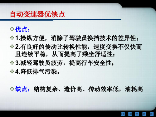
自动变速器优缺点
C1-后输入轴-后齿圈-后行星架 (D-2)
辛普森式自动变速器
可实现发动机制动
(2-2)
辛普森式自动变速器
后齿圈和太阳轮均和后输入轴刚性连接 直接挡(D-3)
辛普森式自动变速器
超速行星架-超速齿圈 (D-4)
辛普森式自动变速器
C2-前齿圈-输出轴(R)
拉维娜式行星齿轮机构
拉威挪式行星齿轮机构
低速
中高速
带锁止离合器的液力变矩器工作原理
带锁止离合器的液力变矩器工作原理
Hale Waihona Puke 行星齿轮机构行星齿轮机构
行星齿轮机构
若齿圈和太阳轮的齿数比为α,则单排行星齿轮机构的运 动特性方程为: n1+αn2- (1+α)n3=0
行星齿轮机构工作原理
行星齿轮机构
n2=0,i31=n3/n1=1/(1+α)=1/(1+z2/z1) 结果: 同向增速
金属带式无级变速器(CVT)
金属带机械式无级变速器
CVT的关键部件:金属带、工作轮、液压泵、控制系统
双离合自动变速器(DCT) DSG
双离合自动变速器DSG
DSG(Direct Shift Gearbox):“直接换 挡变速器”,DSG有别于一般的半自动变 速箱系统,它是基于手动变速箱而不是自 动变速箱,因此,它也是AMT(机械式自 动变速器)的一员。 采用了2个离合器和6个前进档的传统齿轮 变速器作为动力的传送部件,DSG变速器 没有变矩器,也没有离合器踏板。
液力变矩器工作原理
增矩过程: MW=MB+MD
液力变矩器工作原理 偶合点:MW=MB
液力变矩器工作原理
减矩过程:MT=MB-MD (导轮不转) MT=MP(加装单向离合器后 ,导轮转动)
自动变速箱所有品作业肩部估计图表说明书
S U P P O R TB AC K ED BYThis page intentionally left blank.Automated Manual TransmissionAll-Makes Gears and Components CatalogI-Shift/mDRIVE™AT2412C (4)AT2512C (19)AT2812C (35)ATO2512C (51)ATO3112C (67)AT2412D (83)AT2612D (98)AT2812D (114)ATO2612D (130)ATO3112D (146)ATO3512D (162)AT2412E (178)AT2612E (193)AT2812E (209)ATO2612E (225)ATO3112E (241)ATO3512E (257)AT2412F (273)AT2612F (289)AT2812F (305)ATO2612F (321)ATO3112F (337)ATO3512F (353)SPO2812 (369)PTO (385)Kits (392)DT12®211 (Direct Drive Model B) (396)230 (Over Drive Model B) (409)281 (Direct Drive Model A) (422)330 (Over Drive Model A) (435)PTO (449)Kits (450)This guide is periodically updated. The most current information can be found at 4Item Part Number Industry Number Description Qty NotesEAIS2100841121008411Seal and Bearing Kit 1Type A EAIS2100841221008412Seal and Bearing Kit 1Type B11521473Snap Ring -3.20 mm 011521474Snap Ring -3.30 mm 011521475Snap Ring -3.40 mm 01EAIS2342341423423414Snap Ring -3.50 mm 02EAIS2048342620483426Oil Seal13EAIS2162606321626063Bearing -85x150x30.5 mm 14EAIS16540881654088Bearing -92x100x27 mm 15EAIS2077678320776783Gear -31 T 15EAIS2085444120854441Gear -31 T 16EAIS2076051520760515Synchro Cone 27EAIS81717378171737Synchro Ring 28EAIS2077170220771702Input Shaft -358.50 mm 19EAIS2084547720845477Synchro Spring 410EAIS2076677420766774Synchro Pin411EAIS2076051220760512Synchro Sliding Sleeve 19, 10EAIS2084549720845497Synchro Spring and Pin Kit 16, 7, 9, 10, 11EAIS21671426C21671426Synchro Kit1I-Shift/mDRIVE™ A T2412CInput ShaftThis guide is periodically updated. The most current information can be found at 5I-Shift/mDRIVE™ A T2412C Main ShaftItem Part Number Industry Number Description Qty Notes1EAIS16561161656116Bearing -40ID x 38T mm 12EAIS15214491521449Lock Nut13EAIS15215961521596Bearing -65ID x 34T mm 241521625Spacer -9.30 mm 041521626Spacer -9.33 mm 041521627Spacer -9.36 mm 041521628Spacer -9.39 mm 041521629Spacer -9.42 mm 041521630Spacer -9.45 mm 041521631Spacer -9.48 mm 041521632Spacer -9.51 mm 041521633Spacer -9.54 mm 041521634Spacer -9.57 mm 041521635Spacer -9.60 mm 041521636Spacer -9.63 mm 041521637Spacer -9.66 mm 041521638Spacer -9.69 mm 041521639Spacer -9.72 mm 041521640Spacer -9.75 mm 041521641Spacer -9.78 mm 041521642Spacer -9.81 mm 041521643Spacer -9.84 mm 041521644Spacer -9.87 mm 041521645Spacer -9.90 mm 041521646Spacer -9.93 mm 041521647Spacer -9.96 mmI-Shift/mDRIVE™ A T2412C Main ShaftItem Part Number Industry Number Description Qty Notes 41521648Spacer -9.99 mm0 41521649Spacer -10.02 mm0 41521650Spacer -10.05 mm0 41521651Spacer -10.08 mm0 41521652Spacer -10.11 mm0 41521653Spacer -10.14 mm0 41521654Spacer -10.17 mm0 41521655Spacer -10.20 mm0 41521656Spacer -10.23 mm0 41521657Spacer -10.26 mm0 41521658Spacer -10.29 mm05EAIS2077131120771311Gear -35 T16EAIS2236856222368562Synchro Sliding Sleeve17EAIS2053222020532220Synchro Hub18EAIS2053221220532212Gear -41 T18EAIS2054006220540062Gear -41 T19EAIS16525751652575Bearing -90x98x46 mm110EAIS16525781652578Bushing111EAIS2054240020542400Sensor Wheel -30 T111EAIS2103400621034006Sensor Wheel -72 T112EAIS2090648620906486Gear -46 T113EAIS15214521521452Bearing -95x103x60 mm114EAIS2236856222368562Synchro Sliding Sleeve115EAIS2073922920739229Main Shaft116EAIS16525751652575Bearing -90x98x46 mm117EAIS2276334222763342Reverse Gear -34 T118EAIS2162605721626057Bearing -85x150x38.5 mm1 1925640730Thrust Washer -0.90 mm0 1925640731Thrust Washer -0.94 mm0 1925640732Thrust Washer -0.98 mm0 1925640751Thrust Washer -1.74 mm0 1925640752Thrust Washer -1.78 mm0 1925640753Thrust Washer -1.82 mm0 1925640754Thrust Washer -1.86 mm0 1925640755Thrust Washer -1.90 mm0 1925640756Thrust Washer -1.94 mm0 1925640757Thrust Washer -1.98 mm0 1925640733Thrust Washer -1.02 mm0 1925640734Thrust Washer -1.06 mm0 1925640735Thrust Washer -1.10 mm0 1925640736Thrust Washer -1.14 mm0 1925640737Thrust Washer -1.18 mm0 1925640738Thrust Washer -1.22 mm0 1925640739Thrust Washer -1.26 mm0 1925640740Thrust Washer -1.30 mm0 1925640741Thrust Washer -1.34 mm0 1925640742Thrust Washer -1.38 mm0 1925640743Thrust Washer -1.42 mm06This guide is periodically updated. The most current information can be found at I-Shift/mDRIVE™ A T2412C Main ShaftItem Part Number Industry Number Description Qty Notes1925640744Thrust Washer -1.46 mm01925640745Thrust Washer -1.50 mm01925640746Thrust Washer -1.54 mm01925640747Thrust Washer -1.58 mm01925640748Thrust Washer -1.62 mm01925640749Thrust Washer -1.66 mm01925640750Thrust Washer -1.70 mm01925640758Thrust Washer -2.02 mm01925640759Thrust Washer -2.06 mm01925640760Thrust Washer -2.10 mm01925640761Thrust Washer -2.14 mm01925640762Thrust Washer -2.18 mm01925640763Thrust Washer -2.22 mm01925640764Thrust Washer -2.26 mm01925640765Thrust Washer -2.30 mm01925640766Thrust Washer -2.34 mm01925640767Thrust Washer -2.38 mm01925640768Thrust Washer -2.42 mm020EAIS2133927021339270Spacer Ring121EAIS2232875222328752Snap Ring -4.5 mm22220507504Snap Ring -3.70 mm02220507503Snap Ring -3.80 mm02220507502Snap Ring -3.90 mm02220507501Snap Ring -4.00 mm02220507500Snap Ring -4.10 mm02220507499Snap Ring -4.20 mm02220483569Snap Ring -4.30 mm023EAIS2074003920740039Split Ring -3.50 mm224EAIS949656949656O-Ring -19.2x3.0 mm225EAIS2101654821016548Oil Distributor Tube11, 2, 3, 4, 5, 6,7, 8, 9, 12, 13,EAIS2167143321671433Repair Kit -Main Shaft114, 16, 17This guide is periodically updated. The most current information can be found at 7This guide is periodically updated. The most current information can be found at 8I-Shift/mDRIVE™ A T2412C Planetary CarrierItem Part Number Industry Number Description Qty Notes1EAIS2102141621021416Planetary Complete Assembly 1Type B120590147Planetary Complete Assembly 1Type A - Without Retarder 120590148Planetary Complete Assembly 1Type A - Without Retarder 120733119Planetary Complete Assembly 1Type A - With Retarder 120733118Planetary Complete Assembly 1Type A - With Retarder 2EAIS2175123321751233Synchro Cone w/o Retarder 1Without Retarder 2EAIS2175364221753642Synchro Cone w/ Retarder 1With Retarder 3EAIS2111072821110728Synchro Sleeve w/o Retarder 1Without Retarder 3EAIS2111072621110726Synchro Sleeve w/ Retarder 1With Retarder4EAIS2151039521510395Shift Fork 151652847Threaded Rod 26EAIS2057153420571534Gear Shift Rail 17EAIS2143023921430239Synchro Ring 17EAIS2148285621482856Synchro Ring 18EAIS2073731020737310Snap Ring 19EAIS951080951080Snap Ring -4.00 mm 110EAIS2110869521108695Synchro Cone 110EAIS2148284721482847Synchro Cone 11120534543Screw112EAIS2058599420585994Retarder Gear -63 T 1Type A - With Retarder 12EAIS2101066721010667Retarder Gear 1Type B - With Retarder 13EAIS2117062421170624Bearing -70x140x26 mm 1Type A 13EAIS2078544820785448Bearing -80x140x26 mm 1Type B14EAIS914556914556Snap Ring -4.00 mm 014EAIS16528021652802Snap Ring -3.70 mm 014EAIS16528031652803Snap Ring -3.80 mm 014EAIS16528041652804Snap Ring -3.90 mmI-Shift/mDRIVE™ A T2412C Planetary CarrierItem Part Number Industry Number Description Qty Notes153191944Sensor Wheel1Type A15EAIS2077424220774242Sensor Wheel1Type B16EAIS16527761652776Oil Seal1Type A16EAIS2079130520791305Oil Seal -96x145x10 mm1Type B17EAIS16526221652622Oil Seal -90x11x8 mm1Type A17EAIS2079122220791222Oil Seal -95x114.5x9.5 mm1Type B181521751Sensor Wheel1Type A18EAIS2078485520784855Sensor Wheel1Type B1921359225Plate220EAIS81726188172618Flange -w/o Retarder1Type A - Without Retarder 20EAIS81726208172620Flange -w/o Retarder1Type A - Without Retarder 2020498990Flange1Type A - With Retarder20EAIS2223821222238212Flange1Type B21969818Screw222EAIS976053976053O-Ring1Type A22EAIS976055976055O-Ring1Type B23EAIS81713388171338Lock Nut12420483601Thrust Washer102520483600Thrust Washer102620483611Side Pinion527EAIS16561131656113Needle -0.6x18.9 mm22028Spacer527, 2822544210Needle Kit52920515814Pin53022761641Side Pinion Kit1With 4 Side Pinions30EAIS2276170122761701Side Pinion Kit1With 5 Side Pinions1, 30EAIS2105068321050683Planetary Carrier Kit1Type B - With Retarder1, 3021050684Planetary Carrier Kit1Type B - With Retarder1,30EAIS2105062121050621Planetary Carrier Kit1Type B - Without Retarder 1,30EAIS2105067521050675Planetary Carrier Kit1Type B - Without Retarder 2,7,10EAIS2176892621768926Synchro Ring Kit1Without Retarder2,7,10EAIS2176892721768927Synchro Ring Kit1With Retarder2, 3, 7, 8, 9,EAIS2167143521671435Synchro Ring Kit1Without Retarder10, 11, 23This guide is periodically updated. The most current information can be found at 9This guide is periodically updated. The most current information can be found at 10I-Shift/mDRIVE™ A T2412C Counter ShaftItem Part Number Industry Number Description Qty Notes11652796Snap Ring -2.00 mm 011652797Snap Ring -2.10 mm 011652798Snap Ring -2.20 mm 011652799Snap Ring -2.30 mm 011652800Snap Ring -2.40 mm 01EAIS16528011652801Snap Ring -2.50 mm 02EAIS21627792n/a Bearing -60x110x38 mm 12EAIS2162606121626061Bearing -60x110x29.75 mm 13EAIS20483432n/a Gear -35 T 13EAIS2085443720854437Gear -44 T 14EAIS2036699020366990Gear -39 T 14EAIS2048343420483434Gear -39 T 15EAIS2054478320544783Gear -28 T 15EAIS2054478120544781Gear -28 T 16EAIS20544785n/a Countershaft 16EAIS2054478720544787Countershaft17EAIS2228363222283632Bearing -60x115x40 mm 1825640700Thrust Washer -0.90 mm 0825640701Thrust Washer -0.94 mm 0825640702Thrust Washer -0.98 mm 0825640703Thrust Washer -1.02 mm 0825640704Thrust Washer -1.06 mm 0825640705Thrust Washer -1.10 mm 0825640706Thrust Washer -1.14 mm 0825640707Thrust Washer -1.18 mm 0825640708Thrust Washer -1.22 mm 0825640709Thrust Washer -1.26 mmI-Shift/mDRIVE™ A T2412C Counter ShaftItem Part Number Industry Number Description Qty Notes 825640710Thrust Washer -1.30 mm0 825640711Thrust Washer -1.34 mm0 825640712Thrust Washer -1.38 mm0 825640713Thrust Washer -1.42 mm0 825640714Thrust Washer -1.46 mm0 825640715Thrust Washer -1.50 mm0 825640716Thrust Washer -1.54 mm0 825640717Thrust Washer -1.58 mm0 825640718Thrust Washer -1.62 mm0 825640719Thrust Washer -1.66 mm0 825640720Thrust Washer -1.70 mm0 825640721Thrust Washer -1.74 mm0 825640722Thrust Washer -1.78 mm0 825640723Thrust Washer -1.82 mm0 825640724Thrust Washer -1.86 mm0 825640725Thrust Washer -1.90 mm0 825640726Thrust Washer -1.94 mm0 825640727Thrust Washer -1.98 mm0 825640728Thrust Washer -2.02 mm0I-Shift/mDRIVE™ A T2412C Reverse IdlerItem Part Number Industry Number Description Qty Notes 1EAIS2048357020483570Reverse Gear -20 T1 220483575Thrust Washer13EAIS2048357420483574Bearing -38x46x32 mm24EAIS2078505320785053Reverse Gear Shaft1 5984765Screw1I-Shift/mDRIVE™ A T2412C Item Part Number Industry Number Description Qty Notes1EAIS984756984756Screw -M10x5052EAIS2048332720483327Cover 13963947Union 14947281Gasket 15EAIS31926143192614Gasket 26EAIS2101156321011563Piston 17EAIS16539001653900Synchro Pin 18EAIS2166654621666546Discs Kit 19EAIS2049720520497205Gasket 110EAIS31925753192575Piston111EAIS81716688171668Spring -14.6x2.5x23.7 mm 112EAIS31925733192573Pin113EAIS949657949657O-Ring -22.2x3 mm 114K-4516CL22429963Clutch Actuator 11521695307Sensor 116990861Screw 31720780168Screw 218EAIS2048342620483426Oil Seal1191521473Snap Ring -3.20 mm 0191521474Snap Ring -3.30 mm 0191521475Snap Ring -3.40 mm 019EAIS2342341423423414Snap Ring -3.50 mm 020********Tube 12122485772Gasket Kit 12220722721Support 1231521975Retainer Ring 12420860677Gasket 125994923Screw 32620534543Screw 252721679939Front Housing 128951950Dowel Pin 22921176267Dowel Pin 230EAIS2232706322327063Solenoid Valve131EAIS2073964320739643Solenoid Valve Repair Kit 132984741Screw33320742253Solenoid Valve Repair Kit1Front HousingI-Shift/mDRIVE™ A T2412C Item Part Number Industry Number Description Qty Notes122684067Central Gearbox Housing 12EAIS2048357820483578Gasket 1324426193Oil Tube 14994271Screw 25EAIS949657949657O-Ring 1620949977Valve 17966145Plug 1818677Gasket 1921176267Dowel Pin 2108171169Magnet 111EAIS2053703220537032Gasket 112EAIS2219649422196494Oil Pump 11321540428Plug 114977005Gasket 1153192319Plug 11620366642Plug 117977005Gasket 118968064Plug1Center/Rear HousingI-Shift/mDRIVE™ A T2412C Center/Rear HousingItem Part Number Industry Number Description Qty Notes 1920993901Spring12021679590Piston12121176267Dowel Pin3221672170Tube123EAIS944364944364O-Ring224Gearbox Housing Cover1Type G - New Type 2421664147Gearbox Housing Cover1Type G - New Type 2420547687Gearbox Housing Cover1Type G - Old Type 24Gearbox Housing Cover1Type G - Old Type 24EAIS2162902021629020Gearbox Housing Cover1Type H - New Type 24EAIS21636544Gearbox Housing Cover1Type H - New Type 2421336493Gearbox Housing Cover1Type H - Old Type 24Gearbox Housing Cover1Type H - Old Type 2521650454Screw6New Type 251669253Screw6Old Type 2621565745Filter1Type H - New Type 27951951Dowel Pin1New Type28EAIS2232344022323440Gearbox Housing Cover1New Type 2820778541Gearbox Housing Cover1Old Type 2921650454Screw6New Type 291669253Screw5Old Type 3020985060Dowel Pin1New Type 3121550882Gearbox Housing Cover Kit1Type H - New Type 31Gearbox Housing Cover Kit1Type H - New Type 3220571825Oil Tube133976029O-Ring23421176267Dowel Pin33521392881Rear Gearbox Housing1With Retarder 3521556042Rear Gearbox Housing1With Retarder 3521556202Rear Gearbox Housing1With Retarder 3521392880Rear Gearbox Housing1With Retarder 3522550742Rear Gearbox Housing1Without Retarder 3520483508Rear Gearbox Housing1Without Retarder 36943582Plug1371669376Gearbox Housing Cover138994458Screw439948095Dowel Pin540EAIS949647949647O-Ring1411521691Plug14220534543Screw244320810985Complete Oil Cooler14321359570Complete Oil Cooler14420810884Oil Cooler145966863Union24520938688Union246947624Gasket24611998Gasket24721805418Bracket148984761Screw2I-Shift/mDRIVE™ A T2412C Center/Rear HousingItem Part Number Industry Number Description Qty Notes 49984672Union2 50984810Nut1 5121818298Tube1 52190714Union1 53947624Gasket250,51,52,5322429386Tube1 5420710706Union2 5511998Gasket2 56984810Nut1 5721818294Tube1 58190714Union1 59947624Gasket256, 57, 58, 5922429384Tube1 6020700745Boot1Type E 6021426924Boot1Type F 6122343544Screw1 62967343O-Ring1 6321360064Union1 6321983348Union1 6420769993O-Ring1 64967343O-Ring1 651521691Plug1 6620568482Plug1 67466653Spring1 68471085Valve1 69994388Screw870EAIS2205123822051238Oil Filter1 711069997Tube1Type C 72974584O-Ring1 7321723678Cover1Type C 74976974O-Ring1Type C 7520366641Plug1Type C 7622064603Cover1Type DI-Shift/mDRIVE™ A T2412C Control ActuatorItem Part Number Industry Number Description Qty Notes22780683Control Actuator - Complete1With Retarder22780682Control Actuator - Complete1Without Retarder22106416Control Actuator - Kit1Type A22780686Control Actuator - Kit1Type B 121484416Upper Cover1With Retarder 121536238Upper Cover1Without Retarder 2EAIS2078525220785252Gasket Kit1320534545Screw144EAIS2056227020562270Gasket15EAIS2056263620562636Cylinder Kit16EAIS2056263020562630Gasket Kit17EAIS2056211120562111Gear Shift Rail18EAIS2056263520562635Covers Kit19EAIS2056263320562633Covers Kit110EAIS2151317021513170Shift Fork111952007Dowel Pin112EAIS951946951946Lock Pin -3x20113EAIS2085973020859730Synchro Sliding Pad2ø 12 mm13EAIS2054259820542598Synchro Sliding Pad2ø 11 mmItem Part Number Industry Number Description Qty Notes 14EAIS31528233152823Synchro Sliding Pad415EAIS2056264020562640Sensor Kit116EAIS2278128022781280Gear Shift Rail117EAIS2151164921511649Shift Fork118952007Dowel Pin119EAIS81715378171537Synchro Sliding Pad220EAIS2056263120562631Covers Kit121EAIS2178606321786063Gear Shift Rail122EAIS2056262920562629Spring and Pin Kit123994928Screw124EAIS2056264220562642Position Sensor Kit125EAIS2151254121512541Shift Fork1Type A 2521678722Shift Fork1Type B 26EAIS951946951946Lock Pin -3x20127EAIS2130209221302092Gear Shift Rail128EAIS2084591720845917Stop Bracket1 293192982Threaded Pin230EAIS2124469521244695Gasket1New Type 30EAIS81711378171137Gasket1Old Type 31EAIS2106828621068286Pressure Sensor Repair Kit132EAIS2211744122117441Cable Harness Kit132EAIS2217632522176325Cable Harness Kit111,13, 14, 19, 26EAIS2056262820562628Synchro Sliding Pad Kit1Contains Sliding Pad2054259811, 13, 14, 19, 26EAIS2096899920968999Synchro Sliding Pad Kit1Contains Sliding Pad2085973013,14, 26EAIS2264192522641925Synchro Sliding Pad Kit1 I-Shift/mDRIVE™ A T2412C Control ActuatorI-Shift/mDRIVE™ A T2512C Input ShaftItem Part Number Industry Number Description Qty Notes EAIS2100841121008411Seal and Bearing Kit1Type AEAIS2100841221008412Seal and Bearing Kit1Type B 11521473Snap Ring -3.20 mm0 11521474Snap Ring -3.30 mm0 11521475Snap Ring -3.40 mm01EAIS2342341423423414Snap Ring -3.50 mm02EAIS2048342620483426Oil Seal13EAIS2162605721626057Bearing -85x150x38.5 mm14EAIS16540881654088Bearing -92x100x27 mm15EAIS2077678320776783Gear -31 T15EAIS2085444120854441Gear -31 T16EAIS2076051520760515Synchro Cone27EAIS81717378171737Synchro Ring28EAIS2077170020771700Input Shaft -358.50 mm18EAIS2175318121753181Input Shaft -376.50 mm19EAIS2084547720845477Synchro Spring410EAIS2076677420766774Synchro Pin411EAIS2076051220760512Synchro Sliding Sleeve19, 10EAIS2084549720845497Synchro Spring and Pin Kit16, 7, 9, 10, 11EAIS21671426C21671426Synchro Kit1I-Shift/mDRIVE™ A T2512C Main ShaftItem Part Number Industry Number Description Qty Notes 1EAIS16561161656116Bearing -40ID x 38T mm12EAIS15214491521449Lock Nut13EAIS15215961521596Bearing -65ID x 34T mm2 41521625Spacer -9.30 mm0 41521626Spacer -9.33 mm0 41521627Spacer -9.36 mm0 41521628Spacer -9.39 mm0 41521629Spacer -9.42 mm0 41521630Spacer -9.45 mm0 41521631Spacer -9.48 mm0 41521632Spacer -9.51 mm0 41521633Spacer -9.54 mm0 41521634Spacer -9.57 mm0 41521635Spacer -9.60 mm0 41521636Spacer -9.63 mm0 41521637Spacer -9.66 mm0 41521638Spacer -9.69 mm0 41521639Spacer -9.72 mm0 41521640Spacer -9.75 mm0 41521641Spacer -9.78 mm0 41521642Spacer -9.81 mm0 41521643Spacer -9.84 mm0 41521644Spacer -9.87 mm0 41521645Spacer -9.90 mm0 41521646Spacer -9.93 mm0 41521647Spacer -9.96 mm0 41521648Spacer -9.99 mm0I-Shift/mDRIVE™ A T2512C Main ShaftItem Part Number Industry Number Description Qty Notes 41521649Spacer -10.02 mm0 41521650Spacer -10.05 mm0 41521651Spacer -10.08 mm0 41521652Spacer -10.11 mm0 41521654Spacer -10.17 mm0 41521655Spacer -10.20 mm0 41521656Spacer -10.23 mm0 41521657Spacer -10.26 mm0 41521658Spacer -10.29 mm05EAIS2077131120771311Gear -35 T16EAIS2236856222368562Synchro Sliding Sleeve17EAIS2053222020532220Synchro Hub18EAIS2053221220532212Gear -41 T18EAIS2054006220540062Gear -41 T19EAIS16525751652575Bearing -90x98x46 mm110EAIS16525781652578Bushing111EAIS2054240020542400Sensor Wheel -30 T111EAIS2103400621034006Sensor Wheel -72 T112EAIS2090648620906486Gear -46 T113EAIS15214521521452Bearing -95x103x60 mm114EAIS2236856222368562Synchro Sliding Sleeve115EAIS2053222220532222Main Shaft116EAIS16525751652575Bearing -90x98x46 mm117EAIS2276334222763342Reverse Gear -34 T118EAIS2162605721626057Bearing -85x150x38.5 mm1 1925640730Thrust Washer -0.90 mm0 1925640731Thrust Washer -0.94 mm0 1925640732Thrust Washer -0.98 mm0 1925640751Thrust Washer -1.74 mm0 1925640752Thrust Washer -1.78 mm0 1925640753Thrust Washer -1.82 mm0 1925640754Thrust Washer -1.86 mm0 1925640755Thrust Washer -1.90 mm0 1925640756Thrust Washer -1.94 mm0 1925640757Thrust Washer -1.98 mm0 1925640733Thrust Washer -1.02 mm0 1925640734Thrust Washer -1.06 mm0 1925640735Thrust Washer -1.10 mm0 1925640736Thrust Washer -1.14 mm0 1925640737Thrust Washer -1.18 mm0 1925640738Thrust Washer -1.22 mm0 1925640739Thrust Washer -1.26 mm0 1925640740Thrust Washer -1.30 mm0 1925640741Thrust Washer -1.34 mm0 1925640742Thrust Washer -1.38 mm0 1925640743Thrust Washer -1.42 mm0 1925640744Thrust Washer -1.46 mm0 1925640745Thrust Washer -1.50 mm0 1925640746Thrust Washer -1.54 mm0I-Shift/mDRIVE™ A T2512C Main ShaftItem Part Number Industry Number Description Qty Notes 1925640747Thrust Washer -1.58 mm0 1925640748Thrust Washer -1.62 mm0 1925640749Thrust Washer -1.66 mm0 1925640750Thrust Washer -1.70 mm0 1925640758Thrust Washer -2.02 mm0 1925640759Thrust Washer -2.06 mm0 1925640760Thrust Washer -2.10 mm0 1925640761Thrust Washer -2.14 mm0 1925640762Thrust Washer -2.18 mm0 1925640763Thrust Washer -2.22 mm0 1925640764Thrust Washer -2.26 mm0 1925640765Thrust Washer -2.30 mm0 1925640766Thrust Washer -2.34 mm0 1925640767Thrust Washer -2.38 mm0 1925640768Thrust Washer -2.42 mm020EAIS2133927021339270Spacer Ring121EAIS2232875222328752Snap Ring -4.5 mm2 2220507504Snap Ring -3.70 mm0 2220507503Snap Ring -3.80 mm0 2220507502Snap Ring -3.90 mm0 2220507501Snap Ring -4.00 mm0 2220507500Snap Ring -4.10 mm0 2220507499Snap Ring -4.20 mm0 2220483569Snap Ring -4.30 mm023EAIS2074003920740039Split Ring -3.50 mm224EAIS949656949656O-Ring -19.2x3.0 mm225EAIS2101654821016548Oil Distributor Tube11, 2, 3, 4, 5, 6,EAIS2167143321671433Repair Kit -Main Shaft17, 8, 9, 12, 13,14, 16, 17I-Shift/mDRIVE™ A T2512C Planetary CarrierItem Part Number Industry Number Description Qty Notes1EAIS2102141621021416Planetary Complete Assembly1Type B120590147Planetary Complete Assembly1Type A - Without Retarder 120590148Planetary Complete Assembly1Type A - Without Retarder 120733119Planetary Complete Assembly1Type A - With Retarder 120733118Planetary Complete Assembly1Type A - With Retarder2EAIS2175123321751233Synchro Cone w/o Retarder1Without Retarder2EAIS2175364221753642Synchro Cone w/ Retarder1With Retarder3EAIS2111072821110728Synchro Sleeve w/o Retarder1Without Retarder3EAIS2111072621110726Synchro Sleeve w/ Retarder1With Retarder4EAIS2151039521510395Shift Fork151652847Threaded Rod26EAIS2057153420571534Gear Shift Rail17EAIS2143023921430239Synchro Ring17EAIS2148285621482856Synchro Ring18EAIS2073731020737310Snap Ring19EAIS951080951080Snap Ring -4.00 mm110EAIS2110869521108695Synchro Cone110EAIS2148284721482847Synchro Cone11120534543Screw112EAIS2058599420585994Retarder Gear -63 T1Type A - With Retarder 12EAIS2101066721010667Retarder Gear1Type B - With Retarder 13EAIS2117062421170624Bearing -70x140x26 mm1Type A13EAIS2078544820785448Bearing -80x140x26 mm1Type B14EAIS914556914556Snap Ring -4.00 mm014EAIS16528021652802Snap Ring -3.70 mm014EAIS16528031652803Snap Ring -3.80 mm014EAIS16528041652804Snap Ring -3.90 mm0I-Shift/mDRIVE™ A T2512C Planetary CarrierItem Part Number Industry Number Description Qty Notes153191944Sensor Wheel1Type A15EAIS2077424220774242Sensor Wheel1Type B16EAIS16527761652776Oil Seal1Type A16EAIS2079130520791305Oil Seal -96x145x10 mm1Type B17EAIS16526221652622Oil Seal -90x11x8 mm1Type A17EAIS2079122220791222Oil Seal -95x114.5x9.5 mm1Type B181521751Sensor Wheel1Type A18EAIS2078485520784855Sensor Wheel1Type B 1921359225Plate220EAIS81726188172618Flange -w/o Retarder1Type A - Without Retarder 20EAIS81726208172620Flange -w/o Retarder1Type A - Without Retarder 2020498990Flange1Type A - With Retarder 20EAIS2223821222238212Flange1Type B21969818Screw222EAIS976053976053O-Ring1Type A22EAIS976055976055O-Ring1Type B23EAIS81713388171338Lock Nut12420483601Thrust Washer102520483600Thrust Washer102620483611Side Pinion527EAIS16561131656113Needle -0.6x18.9 mm22028Spacer527, 2822544210Needle Kit52920515814Pin53022761641Side Pinion Kit1With 4 Side Pinions30EAIS2276170122761701Side Pinion Kit1With 5 Side Pinions1, 30EAIS2105068321050683Planetary Carrier Kit1Type B - With Retarder 1, 3021050684Planetary Carrier Kit1Type B - With Retarder 1, 30EAIS2105062121050621Planetary Carrier Kit1Type B - Without Retarder 1, 30EAIS2105067521050675Planetary Carrier Kit1Type B - Without Retarder 2, 7, 10EAIS2176892621768926Synchro Ring Kit1Without Retarder2, 7, 10EAIS2176892721768927Synchro Ring Kit1With Retarder2, 3, 7, 8, 9,EAIS2167143521671435Synchro Ring Kit1Without Retarder10, 11, 23I-Shift/mDRIVE™ A T2512C Counter ShaftItem Part Number Industry Number Description Qty Notes 11652796Snap Ring -2.00 mm0 11652797Snap Ring -2.10 mm0 11652798Snap Ring -2.20 mm0 11652799Snap Ring -2.30 mm0 11652800Snap Ring -2.40 mm01EAIS16528011652801Snap Ring -2.50 mm02EAIS2162779221627792Bearing -60x110x38 mm12EAIS21626061n/a Bearing -60x110x29.75 mm13EAIS20483432n/a Gear -35 T13EAIS2085443720854437Gear -44 T14EAIS2036699020366990Gear -39 T14EAIS2048343420483434Gear -39 T15EAIS2054478320544783Gear -28 T15EAIS2054478120544781Gear -28 T16EAIS2054478520544785Countershaft16EAIS20544787n/a Countershaft17EAIS2228363222283632Bearing -60x115x40 mm1 825640700Thrust Washer -0.90 mm0 825640701Thrust Washer -0.94 mm0 825640702Thrust Washer -0.98 mm0 825640703Thrust Washer -1.02 mm0 825640704Thrust Washer -1.06 mm0 825640705Thrust Washer -1.10 mm0 825640706Thrust Washer -1.14 mm0 825640707Thrust Washer -1.18 mm0 825640708Thrust Washer -1.22 mm0 825640709Thrust Washer -1.26 mm0I-Shift/mDRIVE™ A T2512C Counter ShaftItem Part Number Industry Number Description Qty Notes 825640710Thrust Washer -1.30 mm0 825640711Thrust Washer -1.34 mm0 825640712Thrust Washer -1.38 mm0 825640713Thrust Washer -1.42 mm0 825640714Thrust Washer -1.46 mm0 825640715Thrust Washer -1.50 mm0 825640716Thrust Washer -1.54 mm0 825640717Thrust Washer -1.58 mm0 825640718Thrust Washer -1.62 mm0 825640719Thrust Washer -1.66 mm0 825640720Thrust Washer -1.70 mm0 825640721Thrust Washer -1.74 mm0 825640722Thrust Washer -1.78 mm0 825640723Thrust Washer -1.82 mm0 825640724Thrust Washer -1.86 mm0 825640725Thrust Washer -1.90 mm0 825640726Thrust Washer -1.94 mm0 825640727Thrust Washer -1.98 mm0 825640728Thrust Washer -2.02 mm0I-Shift/mDRIVE™ A T2512C Reverse IdlerItem Part Number Industry Number Description Qty Notes 1EAIS2048357020483570Reverse Gear -20 T1 220483575Thrust Washer13EAIS2048357420483574Bearing -38x46x32 mm24EAIS2078505320785053Reverse Gear Shaft1 5984765Screw1I-Shift/mDRIVE™ A T2512C Front HousingItem Part Number Industry Number Description Qty Notes1EAIS984756984756Screw -M10x5052EAIS2048332720483327Cover 13963947Union 14947281Gasket 15EAIS31926143192614Gasket 26EAIS2101156321011563Piston 17EAIS16539001653900Synchro Pin 18EAIS2166654621666546Discs Kit 19EAIS2049720520497205Gasket 110EAIS31925753192575Piston111EAIS81716688171668Spring -14.6x2.5x23.7 mm 112EAIS31925733192573Pin113EAIS949657949657O-Ring -22.2x3 mm 114K-4516CL22429963Clutch Actuator 11521695307Sensor 116990861Screw 31720780168Screw 218EAIS2048342620483426Oil Seal1191521473Snap Ring -3.20 mm 0191521474Snap Ring -3.30 mm 0191521475Snap Ring -3.40 mm 019EAIS2342341423423414Snap Ring -3.50 mm 020********Tube 12122485772Gasket Kit 12220722721Support 1231521975Retainer Ring 12420860677Gasket1I-Shift/mDRIVE™ A T2512C Front HousingItem Part Number Industry Number Description Qty Notes 25994923Screw3 2620534543Screw25 2721679941Front Housing1 28951950Dowel Pin2 2921176267Dowel Pin230EAIS2232706322327063Solenoid Valve131EAIS2073964320739643Solenoid Valve Repair Kit1 32984741Screw3 3320742253Solenoid Valve Repair Kit1。
Volvo I-Shift 自动变速箱操作手册说明书

I-Shift drive modes and software functionsThe I-Shift gearboxʼs functions are optimized with specially adapted drive modes, which make the gearbox even more practical and economical by adapting the gearshift functional-ity to the current transport conditionsThe driving mode is selected with a button on the gear se-lector. Fuel saving functions are adjusted according to the se-lected drive mode. I-See (optional) speed limits and strategy are adjusted according to the selected drive mode.Drive modes•Economy: Focus on lowering fuel consumption, some re-duction in power. Using I-See function.•Standard: Reasonable fuel consumption without compro-mising drivability. Using I-See function.•Performance: Full power, with less focus on fuel consump-tion.•Off-road: Agility is prioritised.•Heavy duty: Optimised for drivability and comfort at high loads (Heavy Equipment Transport).Sales variantsDrive modeDRM-E I-Shift drive mode economyDRM-BE I-Shift drive mode balanced economyAMT vocation optionAVO-BAS Basic I-Shift softwareAVO-ENH Enhanced I-Shift software including construc-tion and off-road applicationsAVO-HD Enhanced I-Shift software including heavy du-ty, construction and off-road applicationsTransmission performance modeTPM-AUTR Transmission performance mode auto return TPM-MAN Transmission performance mode manual UTPM Without drive mode performance in DRM-BEAMT manual shift optionsAMSO-BAS Basic I-Shift gear shiftingAMSO-AUT I-Shift manual gear shift available in automatic mode incl kickdown functionAMT PTO functionsAPF-BAS Basic I-Shift PTO functionsAPF-ENH Enhanced I-Shift PTO functions (Auto Neu-tral/ Reverse Inhibit / Split Box Connection)FEATURES AND BENEFITS•Optimized drivability.•Reduce fuel consumption.•Reduce CO2 footprint.•Simplify selection of drive modes.FACT SHEETI-Shift drive modesI-Shift drive modes icons in instrument cluster.I-Shift drive modes and software functions● Standard, ○ Option, — Not available1Note! Choice of UTPM gives no Performance drive mode.DRM-E+AVO-BAS is designed for long haul transport to secure a good fuel economy.DRM-BE+AVO-BAS is the versatile offer for the majority of the transport segments.DRM-BE+AVO-ENH is adapted for construction operations.DRM-BE+AVO-HD is specially tailored for heavier transport operations.FACT SHEETI-Shift drive modesI-Shift software functions● Standard, ○ Option, — Not available2Only AT2612, ATO2612, ATO3112 and ATO3512.3For Volvo FH16 or for a Volvo with driven front axle.FACT SHEETI-Shift drive modesI-Shift Drive Mode Economy (DRM-E)DRM-E is optimized for fleet usage were driver influence is limited. To access I-See functionality, PVT-MAP needs to be added.This drive mode restricts the possibility to alter among the drive modes. The DRM-E will be locked in Economy mode. I-Shift Drive Mode Balanced Economy (DRM-BE)This is the base which giving ideal selection for most all ap-plications. To optimize further toward a particular vocation, DRM-BE is selected with AVO-BAS, AVO-ENH or AVO-HD. For customer usages with frequent start and stop like garbage collection, a potential to save fuel is to remove the possibility to access performance driving mode. That variant exist for DRM-BE and is called UTPM.For DRM-BE with UTPM, the performance drive mode is removed and consequently also the option with TPM-AUTR. Other options in DRM-BE with UTPM are available like AVO-ENH/AMSO-AUT/APF-ENH.Basic Vocational Functions (AVO-BAS)Allows the driver to choose between the Economy, Standard and Performance driving modes.Enhanced Performance – Bad Roads (AVO-ENH)This optional package is specially adapted to the specific con-ditions of the construction and timber transport segments. The Off-road mode includes various functions that adapt gearshifts and gear selection to poor driving surfaces and hilly gradients. It also includes functions that facilitate starting from standstill in poor driving conditions.Off-road mode is designed to minimise the number of gearshifts required. This is useful during off-road driving. It prevents wheels from spinning out when torque is increased after a gearshift, and prevents missed gearshifts, for example if the road gradient changes sharply. High engine power (high revs) is often required when driving uphill.The driver can also influence the maximum number of down shifts. This is very useful when you shift to a lower gear on a very steep uphill gradient and only want to shift once to a gear strong enough to take you all the way up. Economy, Standard, Performance and Off-road driving modes are available. Summary of the functions in the package:•Engine revs are increased as necessary to provide extra torque when starting off from standstill.•Larger margins before upshifts ensure safer driving if the gradient changes.•Gear selection is adapted to minimise the number of gearshifts and run at slightly higher revs.•Functions that make it easier to keep the same gear when the accelerator pedal position and road gradient change.•The package enables multiple downshifts. This facilitates gearshifts when driving up steep slopes.•Includes a function that speeds up clutch release and makes it easier to rock the vehicle out of trouble if it gets stuck on a soft surface.•When moving the gear lever, the driver can choose the gear that provides the highest possible engine speed. Enhanced Performance – Heavy duty (AVO-HD)AVO-HD optimizes I-Shift for heavy duty transport with high gross combination weights (>85 tonnes). Regardless of the gross combination weight, the driver can always optimize dri-vability by selecting or deactivating the Heavy Duty mode, and activating the long haul mode. The functions in the software package also offer benefits for trucks hauling multiple trailers. AVO-HD also includes AVO-ENH functions (Off-road mode)but the functions in Off-road are only active when the Heavy Duty mode is inactive.Change DirectionEnables fast change of driving direction in for instance maneuvering situations by change direction functionality. Change direction is to select reverse gear at lower vehicle speed and use the accelerator pedal to brake the vehicle and start reversing without letting the foot of the accelerator pedal. Vice versa applies, i.e. reversing the vehicle and thenFACT SHEETI-Shift drive modespush the gear selector into A/M and use accelerator pedal to come into forward driving. Pressing the accelerator pedal more makes the event of changing driving direction to occur faster. Change Direction is activated up to 30 km/h.Note! Change Direction requires AVO-ENH or AVO-HD. Terrain BrakeTerrain brake gives improved off-road agility for Volvo FH16 or for a Volvo with driven front axle.With this function, the driver controlling the vehicle better. For instance, rolling off a stone in terrain, is made in a con-trolled manor by the driver activation.Terrain brake means that the brake is applied when the ac-celerator pedal is released and consequently holds the truck in the position inhibiting free rolling. Terrain brake can be en-gaged below 4 km/h, i.e. at low speeds. Applied terrain brake force is controlled by the retarder brake lever position on the steering column.Note! Terrain Brake requires AVO-ENH or AVO-HD. Transmission Performance Mode Auto Return (TPM-AUTR)Transmission performance mode AUTR. Auto return to drive mode Economy.Enable manual switch (TPM-MAN)Transmission performance mode MAN. Enable manual switch between Economy and Performance mode.Basic Gear Selection Adjustment (AMSO-BAS) Allows the driver to adjust gear selection with the gear lever buttons during engine braking in Automatic mode (gear selec-tor position A).Enhanced Gear Selection Adjustment,incl. Kickdown (AMSO-AUT)This function allows both the automatically selected starting gear and the driving gear in Automatic mode to be adjusted by activating the plus/minus button on the gear lever.The kickdown function selects a gear for maximum acceler-ation. When the kickdown switch on the accelerator pedal is engaged, the system changes the gearshift strategy to max-imise vehicle acceleration. When suitable (e.g. depending on engine speed), this leads to a downshift.Basic PTO Functions (APF-BAS)Facilitates power take-off operation. Pre-defined splitter gear positions determine which splitter gear is used when one or two gearbox power take-offs are engaged.Because gear selection is matched to the engine speed lim-it, it is possible to set parameters for the software. The gear selection is then adapted to any engine speed limits imposed by body-builder functions.Enhanced PTO Functions (APF-ENH)Several functions that aid power take-off operation. I-Shiftʼs power take-off functions make it possible to activate the prop-erties listed below by having the software parameters adjust-ed at an authorised workshop.•Auto Neutral: On command, the driveline is disconnected from the bodybuilder control unit, regardless of the gear leverʼs position, when Auto Neutral is activated.•Reverse Inhibit: When the bodybuilder control unit is-sues the Reverse Inhibit command, the reverse gears are blocked by the transmission system.•Connection of splitter box: Allows connection of a splitter box for operation of high-capacity power take-offs. Direct gear is activated when the bodybuilder module is put in splitter box mode. It is also possible to use all high range gears. Please look into the body builder instructions. Performance ShiftGives faster, gentler shifts through intelligent utilisation of the engineʼs compression brake (VEB brakes), the vehicleʼs clutch and a special gearbox brake.Automatic selection of correct starting gear (1st – 6th gear)is included. The choice of starting gear is determined by gross vehicle weight and road gradient.Gearbox Oil Temperature MonitorContinuously shows the gearbox oil temperature in the infor-mation display.Heavy Start EngagementFor start-up with high revs in Performance mode in 1st gear,resulting in higher starting torque. This function raises the revs to facilitate heavy starts. This is useful, for instance, if the truck is stuck in soft ground.I-RollAutomatic activation and deactivation of a freewheel function in order to cut fuel consumption, which can be reduced by up to several percent. I-Roll is used when neither engine power nor engine braking is needed, for instance on flat roads. When driving with cruise control, I-Roll runs at roughly 1–3 km/h be-low the pre-set speed, which saves fuel. The longer the vehi-FACT SHEETI-Shift drive modescle drives using I-Roll, the more fuel is saved.Smart Cruise ControlInteracts with the vehicleʼs Brake Cruise and ensures that the auxiliary brakes are not activated unnecessarily. The auxiliary brakes are deactivated on downhill stretches to save fuel. This allows increased use of the freewheel function, resulting in improved fuel efficiency.Downhill Cruise ControlDownhill Cruise Control sets a maximum speed to control the vehicle speed in a down-hill.Downhill Cruise Control primarily uses the auxiliary brakes such as the Volvo Engine Brake or the retarder to make sure that the selected speed is not exceeded. Only when required, the wheel brakes are applied.The driver can still use the brake pedal to further lower the speed without deactivating the system.Launch ControlOptimizes gear selection and EBS functions when manoeu-vring at low speeds. Manoeuvring is facilitated because the EBS brakes are automatically engaged when the truck changes direction. This also ensures that the Auto Hold func-tion is activated.It is possible to drive the vehicle forward with the idle regu-lator. This saves unnecessary downshifts and makes it easier to adjust the vehicleʼs speed, for instance when driving in traf-fic queues.Enhanced Shift Strategy4By interacting with EBS 5 and ECS 6, both starting and ma-noeuvring are made easier.This brake mode maximises VEB/VEB+/retarder braking effects by automatically selecting the appropriate gear so the engine runs at high revs. This function compensates for the engine brake when changing gears in brake mode.When changing gears during engine braking, the wheel brakes are activated to compensate for braking moment. This raises braking power and provides smoother gearshifts. Interaction with the braking systems increases safety by preventing the truck from accelerating during gearshifts on steep slopes when braking mode is activated.Heavy Duty GCW Control7Optimizes gear selection for high gross combination weights(according to heavy haulage document). This function improves drivability and fuel economy in the heavy duty trans-port segment. Heavy Duty GCW Control gives the driver ac-cess to the HD (Heavy Duty) driving mode.In HD mode, 1st gear is used as the starting gear and gear selection is adapted to heavier gross combination weights. The gearshifts generally occur at higher revs. HD is activat-ed and deactivated by pressing and holding the modes button on the gear selector for about 3 seconds. The chosen driving mode remains selected when the engine is turned off. Among other things, the DRM-BE-AVO-HD function se-lects the starting gear to suit the gross combination weight, thereby saving the clutch. The entire gear range is utilised, and the gears are changed consistently at high revs to maintain torque and driving comfort.When driving with low gross combination weights or with-out a load, it is easy to deactivate the HD driving mode and return to Economy mode. After this, the driver can switch be-tween available drive modes. This ensures comfortable and fuel efficient driving.Heavy ModeHeavy mode function for trucks with I-Shift - having rear axle RTH3815 - regardless of emission class is as follows:•For driving without load all drive modes can be used.•For driving with load all drive modes - except Economy -can be used. When driving downhill with load - the gear-box shifts down, corresponding to retarder lever position 3. The purpose of downshift is to raise the engine speed to provide more engine braking power to the truck.4 Full functionality requires EBS-MED.5 EBS = Disc Brakes with Electronically controlled Brake System (EBS-STD / EBS-MED)6 ECS = Electronically Controlled Suspension (SUSPL-EC).7 Available only with certain engine/gearbox combinations.Volvo Tech ToolI-Shiftʼs software packages can easily be installed and changed with the help of Volvoʼs analysis and programming tool, Volvo Tech Tool. This is done by authorised dealers and workshops,where the software packages can be further cus-tomised with optional functions and customer parameters. Customer parametersI-Shift also has many options for setting customer parame-ters that optimize the vehicleʼs driving properties in specialFACT SHEETI-Shift drive modesapplications and special transport segments. For instance,the starting gear can be optimized according to the transport conditions. Power take-off operation can also be customised.Customised settings and reprogramming of I-Shift are car-ried out at authorised workshops using the Volvo Tech Tool.FACT SHEETI-Shift drive modes。
lst变速箱原理__解释说明以及概述

lst变速箱原理解释说明以及概述1. 引言1.1 概述在汽车工业中,变速箱扮演着至关重要的角色。
它通过改变发动机输出转矩与车轮之间的传动比例,使汽车能够适应不同的驾驶条件和行驶速度。
LST(Lock-up Slip transmission)变速箱作为一种新兴的传动装置,在提高车辆燃油经济性和性能方面具有巨大的潜力。
1.2 文章结构本文将首先解释说明LST变速箱的基本原理和工作方式。
接着,对LST变速箱在汽车行业中的应用进行概述,并讨论其优势和不足之处。
最后,总结LST变速箱原理对于汽车工业的重要性,并对未来LST技术发展进行展望和挑战预测。
1.3 目的本文旨在介绍读者LST变速箱原理,并深入探讨其在汽车行业中的应用及相关优缺点。
通过了解LST变速箱的特点与工作原理,读者可以更好地理解这一技术并认识到它对于提升汽车性能和燃油经济性所起到的重要作用。
同时,本文也将对LST技术未来可能面临的挑战和发展方向进行分析,为读者展示这一领域的潜在前景。
2. lst变速箱原理解释说明:2.1 变速箱的作用汽车的变速箱是一种重要的传动装置,用于控制发动机输出转矩和车辆驱动力之间的转换,允许汽车在不同速度下进行移动。
通过调整齿轮比,变速箱可以提供多个挡位来适应不同驾驶条件下的功率需求和效率要求。
变速箱确保引擎在工作范围内保持高效运行,并提供合适的力量输出给车轮。
2.2 LST变速箱的定义与特点LST(Lock-Up Slip Torque Converter)变速箱是一种现代化的自动变速器技术。
与传统液力自动变速器相比,LST变速箱采用了更加先进的离合器系统和液压控制方式,以提高油耗和驾驶效率。
LST变速箱具有以下几个特点:- 锁止离合器:LST变速器中使用了一个锁止离合器来将液力传递效率提高到接近100%,从而降低能量损失和内部滑差。
- 多段齿轮组合:LST变速箱通常拥有多个前进挡位和一个倒挡,以适应不同速度和路况下的驾驶需求。
汽车自动变速箱指南说明书

Automatic Transmission:Push and hold the brake pedal,then move the shift lever out of Park (P).Push and hold the lock side of the master door lock switch on the driver’s door.You will hear a clicking sound,and after about 5seconds,you will hear another clicking sound.Release the switch,move the shift lever to Park (P)(automatic transmission),and turn the ignition switch to theACCESSORY (I)position within 5seconds.Push and hold the lock side of the master door lock switch on the driver’s door.You will hear a clicking sound after about 5seconds.Release the switch,and turn the ignition switch to theACCESSORY (I)position within 5seconds.5.4.6. 4.5.Door LocksThe auto door unlocking feature has two (manual transmission)or three (automatic transmission)possible settings:Push and hold the lock side of the master door lock switch on the driver’s door.You will hear a clicking sound,and after about 5seconds,you will hear another clicking sound.Release the switch,and turn the ignition switch to theACCESSORY (I)position within 5seconds.Make sure the shift lever is in Park (P),and close the driver’s door.Turn the ignition switch to the ON (II)position.The driver’s door unlockswhenever you turn the ignition switch to the ACCESSORY (I)position.The auto door unlocking is deactivated all the time.This is the default setting.The driver’s door unlocks when you move the shift lever to the Park position.3.4.1.2.On models with automatic transmission Locks all doors when the shift lever is moved out of Park (P).On models with automatic transmissionOn LX and EX modelsCONTINUEDDoor LocksAuto Door UnlockingTo activate an auto door lock mode:Instruments and ControlsUnlocks driver’s door when the ignition switch is moved out of the ON (II)position.AutomaticTransmission:Make sure the shift lever is in Park (P) (automatic transmission),and close the driver’s door.Turn the ignition switch to the ON (II) position.For manual transmission,go to step 5.Push and hold the brake pedal,then move the shift lever out of Park (P).Push and hold the unlock side of the master door lock switch on the driver’s door.You will hear a clicking sound,and after about 5seconds,you will hear another clicking sound.Release the switch,move the shift lever to Park (P)(automatic transmission),and turn the ignition switch to theACCESSORY (I)position within 5seconds.Make sure the shift lever is inPark (P)(automatic transmission),and open the driver’s door.Turn the ignition switch to the ON (II)position.Set the parking brake.Set the parking brake.1.2.3. 4.5.6. 1.2.3.Door LocksTo activate an auto door unlock mode:To turn the auto door unlock modes off:Push and hold the unlock side of the master door lock switch on the driver’s door.You will hear a clicking sound,and after about 5seconds,you will hear another clicking sound.Release the switch,and turn the ignition switch to theACCESSORY (I)position within 5seconds.Push and hold the unlock side of the master door lock switch on the driver’s door.You will hear a clicking sound,and after about 5seconds,you will hear another clicking sound.Release the switch,and turn the ignition switch to theACCESSORY (I)position within 5seconds.4.5. 3.4.Door LocksInstruments and ControlsParents should decide if their children should be shown how to use this feature.As a safety feature, your vehicle has a release lever on the trunk latch so the trunk can be opened from inside.To open the trunk, push the release lever to the left.To open the trunk, pull the trunk release handle on the left side of the driver’s seat. To protect items in the trunk when you need to give the key to someone else, lock the trunk release handle with the master key,and give the other person the valet key.For more information about child safety, see page .Press and hold the trunk releasebutton on the remote transmitter.39On U.S.EX modelsEmergency Trunk OpenerTrunk。
Volvo I-Shift Dual Clutch 12速手动变速箱说明书

I-Shift Dual Clutch is a gearbox that can be powershifted,giving uninterrupted power transfer to the wheels, at most single-step gear changes. It features 12 gears and it is di-mensioned for 2800 Nm of torque.I-Shift Dual Clutch has a unique and fast gear-changing sys-tem, enabling powershift gear changes.Powershifting makes it possible to perform most single-step shifts with no interruptions in power and torque delivery during gear changing. The large ratio coverage of the gearbox provides high starting traction and low fuel consumption. The advanced software has well-adapted gear change strategies.I-Shift Dual Clutch handles up to 80 tonnes of gross combi-nation weight, ideal for long haul and regional haul operations,including liquid and timber transports.In transports where speed and topography vary a lot I-Shift Dual Clutch is ideal to maintain the highest possible average speed in combination with excellent fuel consumption perfor-mance. The uninterrupted power transfer also contributes to a very smooth ride to be the perfect choice for many sensitive transports.A power take-off, compact retarder and emergency power steering pump can be fitted to the transmission. An oil cooler is required for SPO2812.Long intervals between oil changes promote low operating costs and less environmental impact. With special oil, filter and oil changes take place after a maximum of 450,000 km or every third year.FEATURES AND BENEFITS•Smooth and fast gear changing without torque and power loss, giving an extremely good driving comfort.•Software program package adapts the gear changes to the prevailing transport conditions.•Powershifting is possible for every single-step gearchange except when changing the range gear (gear 6-7).•Possibility of manual gear selection and locking of the cur-rent gear promotes high driving flexibility.•Low weight thanks to compact construction and alumini-um housings.•Suitable for long haul and regional haul operations, includ-ing liquid and timber transports.SPO2812 I-Shift Dual ClutchFACT SHEETTransmissionDual clutch transmissionI-Shift Dual Clutch can be described as “two gearboxes with two clutches”, integrated into one unit. The two clutches are connected to two different input shafts, operating indepen-dently of each other.Since the gearbox has 12 gears, one shaft holds the six odd-numbered gears, while the other holds the six even-numbered gears.When the first gear is engaged its clutch is applied. The sec-ond gear on the second shaft will be engaged, and will be con-nected when it is time for a gear change. Then the torque is transferred to the second clutch, without torque interruption delivered to the wheels.The function is referred to as “Powershifting” and can be performed at all single-step shifts except between gear 6 and 7 (range gear shift). Note that in certain cases and/or condi-tions the gearbox will perform a “normal” gear change, de-pending on software strategy and factors like vehicle GCW and throttle position.The clutches are controlled by the DCCA (Dual Concentric Clutch Actuator), which in turn is pneumatically controlled via the DCVU (Dual Clutch Valve Unit). Another unit, GCU (Gear-box Control Unit), controls the gear changing. The clutches are of the dry type.Two input shafts and synchronised range gearThe main section has two input shafts, three main forward ra-tios and one reverse ratio. A synchronised range gear of plan-etary type is located in the range housing. The dog clutches of the main section are unsynchronised.In all powershifts, a mechanical unit carries out an appropri-ate synchronisation of speeds prior to engaging a gear (while power is transferred in another gear). In other shifts, speed synchronisation is performed by controlling the engine and a brake in the gearbox.Strong and dependable componentsAll the gears are made of special, casehardened steel, pro-viding considerable strength. With helical gears in the main-as well as the range-change section, more gear surface is in mesh at any given time. This promotes quiet operation and high reliability.Flexible gear-changing systemI-Shift is a very flexible gear-changing system. In Auto mode,gears change automatically even with the cruise control en-gaged.In sensitive driving conditions with seat mounted gear se-lector, the driver can switch to the Manual mode. In Manual mode the driver changes gear manually using a button inte-grated into the gear lever. Since clutch operation is controlled by the gear changing system, there is no clutch pedal.I-Shift gear selector in seat or in dashboardFor I-Shift gearboxes, there is a choice between a seat mount-ed and a dashboard-mounted gear selector. The seat mount-ed is best suited for rough or complex driving while the dash-board-mounted selector provides extra room in the cab. For more information, see fact sheet “I-Shift gear selector”.I-Shift drive modes and for optimum efficiencyThe I-Shift gearboxʼs functions are optimized with specially adapted drive modes, which make the gearbox even more practical and economical by adapting the gearshift functional-ity to the current transport conditions. For more information,see fact sheet “I-Shift drive modes and software functions”.Shown on the display: 1. Drive mode 2. I-See symbol (Green = Working / Grey = Engaged “Ready to work”) 3. Automatic gear shifts / Manual gear shifts 4. Selected gear 5. Aux Brakes engaged 6. Brake level in position automatic (A=Brake blend)SPO2812 I-Shift Dual ClutchFACT SHEETTransmissionSPECIFICATIONType designation.......................................................................SPO2812Generation................................................................................................A Type.................................................Dual clutch over drive transmission Max incoming torque...............................................................2800 Nm Max gross combination weight..............................................80 tonnes Number of forward gears......................................................................12Number of reverse gears.........................................................................4Weight without oil.........................................................................307 kg Oil-change volume.................................................................approx. 16 l Oil-change volume incl. oil cooler with normal capacity....approx. 16 lOil-change volume incl. oil cooler with high capacity.........approx. 17 lRatios SPO2812SPO2812 I-Shift Dual ClutchFACT SHEETTransmission。
中间轴式五挡变速器传动机构设计

中间轴式五挡变速器传动机构设计[摘要]变速器是汽车传动系中的主要部件之一。
变速器由变速传动机构和变速操纵机构两部分组成。
变速传动机构的主要作用是改变转距和转速的数值和方向;操纵机构的主要作用是控制传动机构,实现变速器传动比的改变,即实现换挡,以达到变速变距。
本题目主要进行轿车三轴五挡机械式变速器的设计,包括变速器的整体结构和齿轮传动部分的设计,并进行相关的计算与校核。
经过设计与校核,该变速器主要结构符合设计标准、零件强度也达到了使用要求。
[关键词] 汽车机械变速器三轴五挡传动比齿轮Five-speed gearbox countershaft type transmission mechanism design[Abstract] Transmission in the automotive transmission lines, one of the most important components. Transmission speed by a variable speed transmission and control mechanism of two parts. The main role of the variable-speed transmission is to change the value of torque and rotational speed and direction; manipulation of the organization's main role is to control the transmission mechanism, transmission gear ratio to achieve the exchange, that is, to achieve shift in order to achieve variable-speed pitch. This subject, mainly for automotive six-axis mechanical transmission gear structural design, including the gear drive parts, control of part of the, etc., and the associated calculation and verification, through the design and verification,The main structure of the transmission line design standards, parts intensity reached the use requirements.[Keywords] Automotive Mechanical Transmission;Axis 5 block ;gear ratio;gear wheel引言 (1)第1章概论 (2)1.1选题背景与意义 (2)1.2变速器的功用与要求 (3)1.3 原始设计参数 (3)第2章手动变速器工作原理 (4)第3章机械式变速器方案的确定 (7)3.1 变速器结构方案的确定.............................. 错误!未定义书签。
优化再优化
沃尔沃秉承实用、简约、可靠、轻便的斯堪的那维亚民族的精神,成为其创新技术和突破自我的原动力。
在“山寨”成为流行词汇的今天,民众自娱自乐的精神被发挥到了极至,从大众创新浪潮当中,我们除了娱乐之外同时也产生了“雷”和“?”的感受。
毕竟产生于民间的“山寨”难以掩饰自身的无力和苍白。
面对当前这个跌宕起伏的市场环境,“创新”无疑被众多企业一直挂在口边,科技转换生产力的神话被多少人传颂,但现实的技术与产品创新真的这么容易吗?我们的技术日新月异,但真正有能力将技术转化到产品中还是少数。
“让销售更好的一个办法,就是把产品做得更有吸引力,并迎合时代的变迁。
”在今天被经济危机撞击的不知所措的企业家们,也许还是应该把这句话奉为宝典。
至少沃尔沃是这么做的。
2009年2月7日,沃尔沃卡车新品发布以“全程尊享,驾驭挑战”为主题在充满魅力的海滨城市青岛隆重举行。
活动现场,沃尔沃卡车在华主力车型fm和fh升级新品闪亮登场,与同期到访的沃尔沃环球帆船赛赛船交相辉映,场景盛大;同时,沃尔沃享誉全球的金牌服务协议也正式引入中国。
新年伊始,作为行业领袖的沃尔沃卡车无疑给整个中国市场注入了新的活力与信心。
i-shift:节油专家有着巨大工作强度的卡车司机都梦想一部能将手动变速箱的稳健和自动变速箱的方便完美结合的卡车,在沃尔沃新车型上,我们体验到了!实现这一梦想的技术是――i-shift智能换档系统,i-shift颠覆了传统变速箱,取消了离合器踏板和换档手柄,通过油门和制动踏板控制车辆的加减速。
与手动变速箱相比i-shift更轻,运动零件更少,而且电子同步可以使换档更迅捷,与普通的自动变速箱相比,i-shift可提供多达12个传动比,其传动比更为合理,最大优势是既能提高驾驶员的驾乘舒适性,又具有良好的燃油经济性。
在加速和减速过程中,变速箱可以平稳、流畅地变速,发动机和变速箱电子设备控制换挡,从而改变档位来适应当前的行驶工况,i-shift使发动机始终保持在最经济的转速范围内。
DSGCVTVVTESP汽车常见英文术语介绍
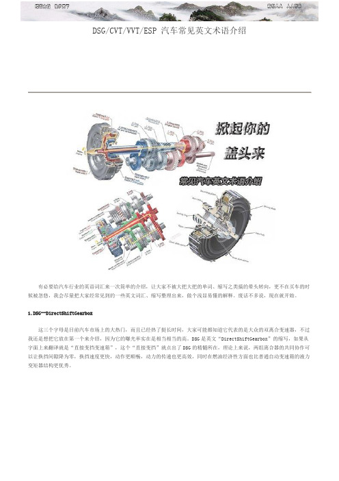
DSG/CVT/VVT/ESP 汽车常见英文术语介绍有必要给汽车行业的英语词汇来一次简单的介绍,让大家不被大把大把的单词、缩写之类搞的晕头转向,更不在买车的时候被忽悠,我会尽量把大家经常见到的一些英文词汇、缩写整理出来,做个浅显易懂的解释。
废话不多说,现在就开始。
1.DSG--DirectShiftGearbox这三个字母是目前汽车市场上的大热门,而且已经热了挺长时间,大家可能都知道它代表的是大众的双离合变速器,不过我还是想把它放在第一个来介绍,因为它的曝光率实在是相当相当的高。
DSG是英文“DirectShiftGearbox”的缩写,如果从字面上来翻译就是“直接变挡变速箱”,这个“直接变挡”就点出了DSG的精髓所在,理论上来说,两组离合器的共同协作可以让换挡间隙降为零,换挡速度更快,动作更顺畅,动力的传递也更高效,同时在燃油经济性方面也比普通自动变速箱的液力变矩器结构更优秀。
大家不要以为所有双离合变速器都叫DSG,这只是大众对他们产品的命名而已,其他厂商也有自己的双离合变速器产品和自己的命名,比如保时捷的PDK——PorscheDoppelKupplung、宝马的M-DCT——M-DualClutchesTransmission、三菱的TC-SST——TwinClutch-SportShiftTransmission、福特的PowerShift(这个名字比较短,所以没用简写)。
所有这些产品名称迥异,设计初衷、内部结构不尽相同,但都是双离合变速箱产品。
2.CVT--ContinuouslyVariableTransmission把这个列上来之前我纠结了片刻,因为从技术角度来说它已经不新鲜了,但是不排除还有一部分网友不清楚这三个字母的全称,所以还是有必要提上来亮个像:ContinuouslyVariableTransmission,也就是传说中的“无级变速”。
由于没有物理意义上的挡位,搭载这种变速器的汽车在正常行驶当中是感受不到顿挫的,除非你虐待油门踏板。
变速器的文献总结

变速器的文献总结变速器是汽车传动系中最主要的部件之一。
变速箱由变速传动机构和变速操纵机构两部分组成。
变速传动机构的主要作用是改变转距和转速的数值和方向;操纵机构的主要作用是控制传动机构,实现变速器传动比的交换,即实现换档,以达到变速变距。
标签:变速器;中间轴;设计;传动比;齿轮目前国际上存在5种自动變速器,即液力机械式自动变速(automatictransmission,AT)、电控机械式自动变速器(automated mechanicaltransmission,AMT)、机械无级式自动变速器(continuously variabletransmission,CVT)、无限变速机械式自动变速器(infinitely variabletransmission,IVT)、双离合器式自动变速器(dual clutch transmiss ion,DCT).上,通过分析这5种自动变速器的传动机理、发展历史、研究现状、生产与应用情况和优缺点,总结其共性关键技术,提出发展趋势,以达到对自动变速器的全面认识。
一、五种变速器的发展历史20世纪30年代后期到50年代是AT的成长期,多采用液力偶合器和行星齿轮变速器;60年代采用多元件工作轮;70年代使用闭锁离合器;80年代采取增加挡位和使用电子控制的技术,近几年,则通过采用CAD/CAM技术来提高生产效率。
1985年,日本五十铃公司率先研制成功NA VI-5型全自动机械式变速器并装车.1986年,AMT技术第1次应用在F1法拉利赛车上.1995年,本田的部分Civic 轿车装载了AMT.1996年,宝马M3轿车M序列式变速器采用了全新电液控制系统,有自动和手动2种模式.ZF公司也推出了新产品ASTronic系列,可以灵活选择各种驾驶模式(动力型或经济型),并将变速器所有功能集成在一个单元里,提高其可靠性,是世界上第一台完全一-体化的AMT.2006年,马瑞利公司推出了第3代AMT产品,换挡时间大幅缩短,控制在300ms以内。
Eaton UltraShift HV自动变速箱产品介绍说明书
Fleet Manager, Paclease Dealer Agree UltraShift® HV Transmissions Are the Right MoveLocation Details:Winnipeg, Manitoba, Canada Segment Details:Moving & Delivery Trucks Challenge:Needed a transmission that would endure driver behavior, as well as help reduce the need for repairs and maintenence.Solution:Eaton’s UltraShift HV automated transmission.Results:Eliminated maintenence needs because drivers cannot be as aggressive when operating an automated transmission.Contact Information:Eaton CorporationVehicle GroupP.O. Box 4013Kalamazoo, MI 490031-800-826-HELP (4357)/roadranger “With the UltraShifttransmissions, the elec-tronics are doing theshifting for you, and thetransitions from gear togear are always smooth.That has effectivelyeliminated maintenanceissues.”Cameron Quinn (left), driver, Two Amigosshown with Brad Prociuk, fl eet manager,Two Amigos.BackgroundTwo Amigos, a furniture deliveryfleet and moving company, takesits name from a storefront signthat co-owner Larry Calen sawwhile vacationing in Mexico. Theother co-owner, or co-Amigo, isDoug Creighton. Together thepair has built a business thatis “muy bueno,” with facilitiesthroughout Canada and a fleetthat now includes roughly 52trucks and highway tractors.Brad Prociuk is fleet manager atthe Winnipeg location. He hasbeen with Two Amigos for morethan 14 years and has the bulkof the company’s trucks underhis care in Winnipeg. His vehi-cles typically operate up to 12hours a day, making anywherefrom 10 to 16 daily deliveries.Prociuk leases his vehicles fromCTS Lease & Rental, his localPaclease representative, as partof a full service lease agree-ment. Kelly Whyte is the CTSservice manager.ChallengesProciuk and Whyte both workto assure that the Two Amigosvehicles are on the road mak-ing money, not in the shop forunnecessary repairs.“We have been using standardtransmissions for a long time,but no one wants to drive themthe way you are supposed todrive them,” says Prociuk. “Wewere going through way toomany clutches and synchroniz-ers. I had one driver who burnedout a clutch in six months. Itwas unbelievable.”Says Whyte, “As part of thelease agreement with TwoAmigos, we are responsiblefor maintenance on the newvehicles. We have a fixed ratefor the lease and a fixed rate tolook after the maintenance. Soif we are seeing, for example,excess tire wear or brake wearsooner than we projected, we’respending more money maintain-ing them than we are bringinginto the company.”Whyte adds that CTS doesn’tlike having to bill anything backto its customers. “So if we canadd components into the pow-ertrain that help eliminate driverabuse, it’s good for everyone.We are going to be able to keepthose trucks on the road longer,only coming in for scheduledpreventative maintenance.”S U P P O R TB AC K ED B YNote: Features and specifications listed in this document are subject to change without notice and represent the maximum capa-bilities of the software and products with all options installed. Although every attempt has been made to ensure the accuracy of information contained within, Eaton makes no representation about the completeness, correctness or accuracy and assumes no responsibility for any errors or omissions.Features and functionality may vary depending on selected options.UltraShift is a registered trademark of Eaton Corporation.All other trademarks are property of their respective owners.SolutionsLocal Roadranger representa-tive Ken Moodie suggested that CTS Lease specify Eaton auto-mated transmissions with two new trucks he was ordering for Prociuk.Prociuk soon took delivery of two new Kenworth T370 medium-duty straight trucks with Eaton UltraShift HV trans-missions, a fully automateddesign for Class 6 and 7 vehicles with diesel engines in the 195-260 horsepower range. Capable of handling torque capacities up to 660 pounds per foot and loads up to 33,000 pounds gross vehicle weight, the UltraShift HV transmission is ideally suited for pickup-and-delivery applications.Other key features and benefits of the UltraShift HV transmis-sion include Hill-Assist, which automatically minimizes rollback on up to 10 percent grades while the operator makes the transition from the brake pedal to the accelerator. This feature benefits the driver in both uphill and downhill stop and start situations. Additionally, theUltraShift HV transmission’s two-pedal design eliminates manual shifting, allowing operators to keep both hands on the wheel for safer, less stressful vehicle operation.Results“We were told that theUltraShift transmissions were pretty much bulletproof in terms of potential driver abuse,” says Prociuk. “So far, that has cer-tainly been the case.“With the UltraShift transmis-sions, the electronics are doing the shifting for you, and thetransitions from gear to gear are always smooth. That has effec-tively eliminated maintenance issues.” Whyte attributes that to the fact that the drivers cannot be too aggressive when operating an automated transmission. “The transmission helps slow them down,” says Whyte. “It’s a win/win situation for us and for the customer.“I’m excited, as the transmis-sions are definitely going to show some savings. Plus the reliability of the equipment is going to benefit Brad and Two Amigos. The trucks are going to be working instead of in the shop. Everyone wins with these transmissions.”lKelly Whyte, CTS lease and rental service managerS U P P O R TB AC K ED B YFor spec’ing or service assistance, call 1-800-826-HELP (4357) or visit /roadranger . In Mexico, call 001-800-826-4357.Roadranger: Eaton and trusted partnersproviding the best products and services in the industry, ensuring more time on the road.Eaton Corporation Vehicle Group P .O. Box 4013Kalamazoo, MI 49003 USA 800-826-HELP (4357)/roadranger © 2012 Eaton CorporationAll Rights Reserved. Printed in USA.TRSL2509 0512。
变速箱设计说明书
摘要变速箱的重要动作就是更换不同的齿轮组合,我们可以拨动手排档的档位来改变齿轮的相对位子,借着不同齿轮间的咬合与连接,以达到变换“齿轮比”(简称齿比)的目的,完成我们换档的目的。
有级式变速器是目前使用最广的一种。
它采用齿轮传动,具有若干个定值传动比。
本次设计从最大、最小转速参数的设计到标准公比的选用到转速的确定、齿数、齿轮的确定等都严格按照要求设计。
查阅了多种设计资料确定了主传动系统结构、转速图,各轴直径的计算和它们刚度强度的校核,齿轮的齿数、模数和主传动链的设计,从而确定了主轴箱的大体结构,从而绘制出装配图和各向视图。
关键词:主轴齿轮箱体轴承AbstractGear box's important movement is the replacement different gear combination, we may dial begin gear's files position to change gear's relative seat, is borrowing linking and the connection between the different gear's, achieves the transformation “the gear ratio” (i.e. tooth ratio) the goal, completes the goal which we shift gears. The having steps type transmission gearbox uses the broadest one kind at present. It uses the gear drive, has certain definite value velocity ratio. this design from biggest, and the least turns soon the parameter designs the standard compares of choose to use to turn to really settle soon, wheel number, the wheel gear really settles etc. all strict design according to the request. Checking various designs data made sure the main drive to move the system construction and rotate speed diagram, diameter calculation in each axes with they just checkout the intensity of them, the wheel of the wheel gear number, the modulus and the design of the main drive to move a chain, thereby make sure the big body structure of the principal axis box, thus draw an assemble diagram with each to see diagram.Keyword: principal axis gear box bearing绪论设计的过程是通过分析、创造和综合而达到满足特定功能目标的一种活动。
牵引车性能参数对比

大运 N9 重卡 480 大运 N9重卡 480 马力 6X4 马力 6X4牵引车 牵引车 (CGC4255D4ZCA (CGC425 ) 5D4ZCA) 厂商指导价: 35.67万 33.8万
基本信息
公告型号: CGC4255D4ZCA 驱动形式: 轴距: 车身长度: 车身宽度: 车身高度: 6X4 3300+1350mm 6.955米 2.5米 3.68米 CGC4255 D4ZCA 2646 2646
24.0吨 26.0吨 26.0吨 49.0吨 40.0吨 26.0吨 130.0km/ 96.0km/h 113.0km/ h h 德国 德国 德国 重卡 重卡 重卡
40.0吨 49.0吨 120.0km/ 130.0km/ h h 山西运城 德国 重卡 重卡
德国 重卡
发动机
发动机: 汽缸数: 燃料种类: 汽缸排列形 式: 排量: 排放标准: 最大马力: 最大输出功 率: 潍柴 WP13.480E401 6 柴油 直列 12.54L 国四/欧四 480马力 353.0kW 潍柴 奔驰 WP13.48 OM501L 0E40 A 456 6 柴油 直列 12.54L 国四/欧 四 480 马力 6 柴油 V型 11.946L 国四/欧 四 460 马力 6 柴油 V6 奔驰 奔驰 奔驰 OM501L OM502L OM501L A 456 A A 6 柴油 V型 8 柴油 V型 6 柴油 V型
全铝合金 铝合金油 全铝合金 全铝合金 D形油箱 箱 D形油箱 D形油箱 1080.0L 695.0L 1080.0L 1080.0L
13.0t驱动 桥带差速 锁,每桥 四个气 囊,配平3312 后悬浮桥 后悬浮桥 提升 提升 提升
20500kg 2.733 前桥抛物 线弹簧 2.79 后空气悬 挂
从四速到七速 各类常见自动变速箱解析

从四速到七速各类常见自动变速箱解析从四速到七速各类常见自动变速箱解析网易汽车随着城市日益拥堵,手动变速箱的弊病也更加明显。
频繁换挡不说,还得长时间半联动跟着车流涌动,别提有多疲劳。
并且对于大多数新手而言,要想很快适应也不是一件容易的事情。
采用自动变速箱的车型日益增多,种类也更加繁杂,市场上常见就有4速,5速,6速,甚至包括7速DSG还有CVT无级变速箱等等。
这些变速箱该如何选择与区分,我们下面就用简单明快的语言为大家做一个详细介绍。
一、4 速自动变速箱优点:成本较低,实用性强,多装配在小型车和紧凑车型上缺点:油耗和舒适性略差代表车型:世嘉,标致207 ,308 ,408 ,福克斯,马自达3 老款或星骋1.6L ,凯越,悦动,福瑞迪,嘉年华,雅力士,雨燕等等[世嘉10.88-14.98万] | 参数| 文章| 图库| 论坛|一般来说,车企选择4速自动变速箱的想法虽然不尽相同,但有两点是共同的,首先是容易控制成本,相比那些5速或6速机械式自动变速箱,它的齿轮只有4组,结构要简单一些,实际上也能满足大部分人用车需要。
不过4速自动变速箱有一个明显的缺点,那就是变速箱配备动力输出的平顺性一般,油门稍大,其舒适性就不太令人满意,同时油耗也不十分理想当然,这一切的不足归根结底会被性价比所掩盖。
所以在10万元左右以及以内的车型,4速变速箱是很常见的装备。
4速变速箱从功能而言,也分为普通4速自动和4速手自一体。
普通4速没有手自一体功能,但引入了诸如D3挡,L挡等功能。
可以帮我们实现超车或上下陡坡的需要,有的4速自动挡还会引入雪地模式。
而4速手自一体变速箱在使用上要比普通4速自动变速箱功能更广泛,比如雪地起步,上下陡坡或超车等等,都可以藉由手自一体功能实现。
[雅力士8.7-10.68万] | 参数| 文章| 图库| 论坛|像别克凯越就是采用普通4速自动变速箱,它的使用和一般4速自动变速箱没有什么区别,只是D3变成了D4,如果想要高速超车,可以按换挡界面旁边的HOLD按键,这样就可以自动锁定在D3挡位,D2和D1的用途大家都清楚了,一个可以用来雪地起步,一个用来上下陡坡出于地下车库的用途。
自动变速箱使用指南说明书

Automatic TransmissionNeutral (N) — Use Neutral if you need to restart a stalled engine, or if it is necessary to stop briefly with the engine idling. Shift to Park posi-tion if you need to leave the car for any reason. Press on the brake pedal when you are moving the shift lever from Neutral to another gear.Drive (D 5) — Use this position for your normal driving. Thetransmission automatically selects a suitable gear for your speed and acceleration. You may notice the transmission shifting up at higher speeds when the engine is cold. This helps the engine warm up faster.Sequential SportShift Mode — With the shift lever in "D 5" position, you can select the Sequential SportShift mode to shift gears; much like a manual transmission, but without a clutch pedal.To enter the Sequential SportShift mode, move the shift lever to the left.To return to "D 5", move the shift lever to the right.When you move the shift lever from "D 5" to the Sequential SportShiftmode, the display shows the selected gear.In the Sequential SportShift mode,each time you push forward on the shift lever, the transmission shifts to a higher gear. Pull back on the lever to downshift. The number of thegear selected is displayed next to the "D 5" indicator (see page 166).Even with the Sequential SportShift Mode selected, the transmission will automatically upshift and downshift between first and second gear.CONTINUED +UpshiftDownshiftDrivingAutomatic TransmissionWhen you accelerate away from a stop, the transmission will start in first gear and then automatically upshift to second gear. You have to manually upshift between second and fifth gears. Make sure you upshift before the engine speed reaches the tachometer's red zone. The transmission remains in the selected gear (5, 4, 3). There is no automatic downshift when you pushthe accelerator pedal to the floor.The transmission may automaticallydownshift from the higher gear tothe lower gear under the followingconditions:Driving on level roads and downhillTo shift from4 35 4Speed rangeunder 18 mph(29 km/h)under 34 mph(55 km/h)Driving uphillTo shift from4 35 4Speed rangeunder 34 mph(55 km/h)under 47 mph(75 km/h)Downshifting gives you more powerwhen climbing or provides enginebraking when going down a steep hill.The transmission will also shiftautomatically as the vehicle comes toa complete stop. It will downshift tofirst gear when the vehicle speed isunder 9 mph (15 km/h).If you try to manually downshift at aspeed that would cause the engine toexceed the redline in a lower gear,the transmission will not downshift.The gear indicator will flash thenumber of the lower gear severaltimes, then return to the higher gear.DrivingAutomatic TransmissionIf the car speed slows to below the redline of the selected lower gear position while the indicator is flashing, the transmission willdownshift and the display will show the selected lower gear.If the transmission temperature is below 14 °F (-10 °C), you may not SportShift mode.The table shows the speed ranges for upshifting and downshifting.To shift from2 33 44 5Speed range over 9 mph (15 km/h)over 18 mph (29 km/h)over 34 mph (55 km/h)To shift from3 24 35 4Speed range under 60 mph (96 km/h)under 93 mph (150 km/h)under 125 mph (200 km/h)CONTINUEDDrivingAutomatic TransmissionDrive (D4, D3) — These positions are similar to D5, except when you select the D4 position, only the first four gears are selected. When you select D3, only the first three gears are selected. D4 can also keep the transmission from cycling between fourth and fifth gears in stop-and-go driving, and D3 can keep the transmission from cycling between third and fourth gears.Use D3 when towing a trailer in hilly terrain, or to provide engine braking when going down a steep hill. D3 gives you more power and increased engine braking.For faster acceleration when in D3,D4 or D5, you can get thetransmission to automaticallydownshift by pushing the acceleratorpedal to the floor. The transmissionwill shift down one or two gears,depending on your speed.Second (2) — This position locksthe transmission in second gear. Itdoes not downshift to first gearwhen you come to a stop. Secondgives you more power when climbing,and increased engine braking whengoing down steep hills. Use secondgear when starting out on a slipperysurface or in deep snow. It will helpreduce wheelspin.DrivingAutomatic TransmissionFirst (1) - With the lever in this position, the transmission locks in First gear.If you shift into First position when the vehicle speed is above 31 mph (50 km/h), the transmission shifts into Second gear first to avoid sudden engine braking.Engine Speed LimiterIf you exceed the maximum speed for the gear you are in, the engine speed will enter into the tachometer's red zone. If this occurs, you may feel the engine cut in and out. This is caused by a limiter in the engine's computer controls. The engine will run normally when you reduce the RPM below the red zone.Shift Lock ReleaseThis allows you to move the shift lever out of Park if the normal method of pushing on the brakepedal does not work. This procedure also releases the Reverse Lockout.1. Set the Parking brake.2. Make sure the ignition switch is in the OFF (0) position.To release the Reverse Lockout,make sure the ignition switch is in the ACCESSORY (I) position.CONTINUEDDrivingAutomatic TransmissionCOVER3. Put a cloth on the edge of the ShiftLock Release slot cover next tothe shift lever.Use a small flat-tipped screwdriver or small metal plate (neither areincluded in the tool kit) to removethe cover. Carefully pry off theedge of the cover.SHIFT LOCK RELEASE SLOT4. Insert a screwdriver in the ShiftLock Release slot.5. Push down on the screwdriver andmove the shift lever out of Park toNeutral.To release the Reverse Lockout,move the shift lever from Neutralto Reverse, then Park.6. Remove the screwdriver from theShift Lock Release slot, thenreinstall the cover. Make sure thenotch on the cover is on the rightside. Depress the brake pedal andrestart the engine.If you need to use the Shift LockRelease, it means your car isdeveloping a problem. Have the carchecked by your Acura dealer.Driving。
- 1、下载文档前请自行甄别文档内容的完整性,平台不提供额外的编辑、内容补充、找答案等附加服务。
- 2、"仅部分预览"的文档,不可在线预览部分如存在完整性等问题,可反馈申请退款(可完整预览的文档不适用该条件!)。
- 3、如文档侵犯您的权益,请联系客服反馈,我们会尽快为您处理(人工客服工作时间:9:00-18:30)。
变速箱概述传动比AT2412C、AT2512C 和 ATO2512C 的齿轮传动比列于下表:变速箱结构变速箱由下列三个主要零件组成:离合器壳体、主壳体和高低档壳体。
离合器壳体同时组成主变速箱的前壁。
主壳体包括主轴、中间轴、倒档轴及与控制壳体一体的选档杆。
高低档壳体包括高低档行星齿轮和输出轴。
1.离合器壳体2.主变速箱壳3.缓速器高低档壳体变速箱的主要零件包括输入轴、主轴、带选档装置的高低档档位、中间轴、带倒档轴的润滑油泵及带选档装置的控制壳体。
倒档和基本档位的从动轮位于主轴上。
同时高低档的太阳齿轮与主轴合为一体。
中间轴有固定齿轮。
高低档齿轮包括行星齿轮并与输出轴合为一体。
装备有取力器的变速箱还有一个固定的驱动轴。
1.输入轴2.主轴3.带选档装置和缓速器驱动轮的高低档齿轮4.副轴5.带倒档轴的润滑油泵6.带有换档机构的操纵机构壳体7.取力器驱动轴同步∙半档齿轮(A)同步。
∙主变速箱壳体(B)及其齿轮未同步。
∙高低档齿轮(C)同步。
高低档壳体高低档壳体(C)与下列部件结合:∙取力器;请参见类型可选说明∙紧急动力转向泵∙缓速器装置紧急动力转向泵紧急动力转向泵位于变速箱上,由变速箱输出轴驱动。
由于某种原因正常动力转向电路失效时即启动紧急动力转向泵。
紧急动力转向泵,PSS-DUAL润滑油冷却器变速箱润滑油冷却器功能不会受变速箱有无缓速器的影响。
高低档变速箱高低档同步在齿圈外侧,减小了装置的长度。
大同步区域会缩短选档时间;宽行星齿轮可以提供强大的高低档,斜齿轮会降低行星齿轮运行噪音。
带选档装置和缓速器驱动轮的高低档齿轮控制机构壳体用选档杆选择档位。
一旦选择一个档位,换档到空档之后系统会将发动机扭矩降到合适的水平。
变速箱置于空档,开始换档后即会调节发动机转速与所选档位的转速相符。
控制壳体外盖有两个电气插座,有时会有三个。
未装备缓速器时要应用下列部件:∙I车辆通讯∙II离合器缸∙III—装备缓速器时要应用下列部件:∙I车辆通讯∙II减速器∙II离合器缸控制壳体包括九个电磁阀:1超速变速箱上 HS 和 LS 有反转的功能。
控制壳体包括下列部件:∙四个平行缸、半档、2/3 及 1/R 和高低档。
∙活塞位置的四个感应传感器。
∙两个转速传感器,一个用于主轴,另一个用于中间轴。
输入轴转速由中间轴传感器进行设定。
∙一个润滑油温度传感器,半档和主变速箱的选档叉。
润滑油温度传感器位于转速传感器的电缆处。
∙一个压力传感器。
∙变速箱控制单元,TECU。
气缸与位置传感器的定位∙ A.分段式气缸∙ B. 1/R 气缸∙ C. 2/3 气缸∙ D.高低档变速器气缸∙ E.分段式气缸位置位置传感器和速度传感器的定位∙ A.高低档变速器气缸位置传感器∙ B.副轴速度传感器∙ C.主轴速度传感器∙ D.第二,第三齿轮的位置传感器∙ E. 1 档和倒档缸位置传感器副轴制动中间轴制动器位于中间轴的前端并在选择起步档后对变速箱转动零件进行制动,这将消除变速箱的磨损和噪音。
制动器有时还可以在升档过程中提供更快的换档。
用组合的气动缸启动制动器。
副轴制动离合器缸离合器缸位于离合器壳体里,分布在输入轴的圆周上,其上有一个测量离合器磨损的位置传感器。
控制阀装置位于离合器壳体外侧,用来控制离合器缸。
A. 离合器缸、B. 位置传感器、C. 控制阀装置、D. 控制阀装置通风口。
润滑系统变速箱通过压力和飞溅结合进行润滑。
机油通过油道进入主轴来润滑和冷却傅变速箱,以及输入轴和主轴的轴承。
同时中间轴制动器、输出轴轴承、紧急动力转向泵驱动、缓速器齿轮和取力器也都经过润滑。
润滑系统有两个溢流阀。
一个溢流阀在滤清器阻塞情况下保证变速箱的润滑,而另一个防止系统内压力过大,如冷起动过程中。
溢流阀由一个压缩弹簧和一个阀芯组成。
溢流阀用来保证变速箱的润滑。
溢流阀用来防止润滑油压力过大。
机油泵润滑油泵为偏心泵,由中间轴通过齿轮进行驱动。
油泵固定在倒档轴的两个滚针轴承上。
油泵压力侧有一个插入型的全流润滑油滤清器。
这个滤清器位于主壳体的润滑油滤清器壳体上。
支撑管路安装在固定润滑油滤清器壳体底部的盖上。
支撑管路防止落在外侧的滤清器倾倒。
润滑油位润滑油通过变速箱底部的一个放油塞(1A)和变速箱右侧的一个放油塞(1B)进行排放。
注意:有两个放油塞。
同时可以进行通风的润滑油滤清器放油塞(3)位于右侧。
通过观察孔(2)检查润滑油位。
1A。
变速箱底部的放油塞、1B。
变速箱右侧的放油塞、2. 观察孔、3. 滤清器放油塞。
检查润滑油位的观察孔。
通风装置通过穿过控制壳体上方和控制装置下后方的软管进行通风。
电气系统不带减速器的变速箱传感器和电气接头∙I. 车辆通讯∙II。
离合器缸∙ A. 速度传感器从电气终端I到速度传感器和底盘间的布线。
从插座II到控制阀装置的离合器缸电缆。
带有减速器的变速箱传感器和电气接头∙I. 车辆通讯∙II. 减速器∙III。
离合器缸∙ A. 速度传感器从电气终端I到速度传感器和底盘间的布线。
∙从电气接头II到缓速器间的布线。
∙从插座III到离合器缸控制阀装置的电缆。
气动系统压缩空气接头控制壳体和离合器缸控制阀装置之间的压缩空气接头。
对于高压系统,控制壳体和四位阀之间的压缩空气接头。
对于低压系统,控制壳体和气压缸之间的压缩空气接头。
控制壳体和中间轴制动器之间的气压接头。
动力路线下图说明了 AT2412C 和 AT2512C 的动力传动系。
1档齿轮二档齿轮3档齿轮4档齿轮5档齿轮6档齿轮7档齿轮8档齿轮9档齿轮10档齿轮11档齿轮12档齿轮空档 N1空档 N2倒档齿轮 R1倒档齿轮 R2倒档齿轮 R3倒档齿轮 R4下图说明了 ATO2512C 的动力传动系。
1档齿轮二档起步3档齿轮4档齿轮5档齿轮6档齿轮7档齿轮8档齿轮9档齿轮10档齿轮11档齿轮12档齿轮空档 N1空档 N2倒档齿轮 R1倒档齿轮 R2倒档齿轮 R3倒档齿轮 R4 辅助制动杆在所有装备有缓速器或自动变速箱和发动机制动(VEB)的车辆上,可以通过转向管柱上的拉杆施加辅助制动。
∙0未施加辅助制动∙A自动模式∙1-3手动模式∙B制动程序变速杆固定在驾驶员座椅的选档杆 (GLU)可以折起,来获得驾驶室内的通道。
选档杆控制单元位于仪表板内。
变速杆具备以下功能:1.带回位弹簧的三位开关用来升档或降档。
2.用于降低变速杆至水平位置的按钮。
3.防止汽车自动换档的变速杆自锁装置。
4.选档杆位置:R = 倒档N = 空档A = 自动M = 手动5.按钮E/P用于经济型/性能位置显示屏显示屏提供了当前选择档位和可换入的档位信息。
显示屏分为几个小区域进行显示:1.行驶程序2.所选档位3.可换入档位(升档/降档)4.换档杆位置程序包有关程序包的一般注意事项变速箱具有不同的特征和功能,具体取决于变速箱上安装了哪个程序包。
提供了下列程序:∙基本是标准的变速箱程序∙Distribution & Construction包括使卡车易于操控的功能。
∙Long Haul Fuel & Economy包括一部分提高燃油消耗功能,另一部分使卡车易于操控的功能。
∙Heavy Duty GCM Control为重型卡车设计。
该程序还包括帮助改善燃油经济性和易于操控卡车的功能。
车辆上安装了哪个程序包?换档杆位于空档位置(N)并且压入了按钮 FOLD 时,换档杆可以向前折起。
则显示屏会显示变速箱拥有的程序类型。
更换程序包更换程序包并下载到车上之前一定要进行中央系统(VDA)的更新。
通过将Conversion Kit Number 输入到PC工具中完成此操作,这在零件信息附录中进行定义。
更换后,一定要用 TECU 控制单元(MID 130)进行重新编程,并且变速箱要重新标定。
每个程序包中的功能可选功能类型客户参数变速箱控制单元客户参数:1有关更多的信息,请参见可选说明。
2GJI 仅与 APF-ENH 一同使用;它包括在其它中。
功能描述标准功能变速箱上有下列标准功能。
∙自动选择起步档位。
∙加速踏板释放时自动更换所选档位的可能性。
∙显示屏显示变速箱润滑油温度并且润滑油温度过热时报警系统会通知驾驶员。
可选功能∙EcoRoll(需要 VEB 或缓速器)为减小燃油消耗的目的,该功能自动连接和断开飞轮。
当松开加速踏板时,会断开动力传递,使车辆能空转,发动机降至怠速转速。
∙Smart Cruise Control该功能只有在巡航控制运行时才能启动。
通过在某些条件下禁用辅助制动器来节省燃油。
下坡路段后该功能释放辅助制动器,从而改善巡航控制性能。
∙Launch Controlo无需滑移离合器时,允许怠速发动机行驶。
o拉开时调节发动机扭矩,以获得最佳换档并避免高转速。
Launch Control 的下列功能需要 EBS:o停车过程中轻踩制动踏板通过更平滑的分离改善舒适性。
o关于所选档位,车辆反向转动时会自动施加制动。
o自动施加制动停车并从前进档换到倒档或者从倒档换到前进档。
o HSA,只有在上坡才启动的 Hill Start Aid。
另请参见 Hill Start Aid 的说明:功能组 593,信息类型说明电子控制制动系统(EBS。
∙Enhanced Shift Strategyo空气悬架处于手动模式时自动选择可能的最低档位,以获得最佳的操控性能。
需要 ECS。
o选择增加发动机转速的档位来改善发动机制动性能。
o换档过程中启动制动程序后会暂时施加制动来补偿发动机制动。
该功能需要 ABS-EBS。
如果挂车没有连接 ABS,则会禁用该功能。