烟气轮机说明书资料
汽轮机的运行排烟控制说明书
汽轮机的运行排烟控制说明书说明书1. 概述本文档详细介绍了汽轮机的运行排烟控制方法,旨在帮助操作人员正确控制汽轮机的排烟,保证设备安全运行和环境保护。
2. 排烟管路汽轮机的排烟管路一般分为主排烟管和辅助排烟管,在设计和安装时应注意以下事项:(1)排烟管路应符合相应标准和规范;(2)排烟管路应平直、疏通,阻力小,有利于排出烟气;(3)排烟管路应考虑维护和检修的便利性;(4)排烟管路应防止烟气泄漏,确保周围环境安全。
3. 排烟控制系统为了保证汽轮机的排烟控制效果,需要采用合适的排烟控制系统。
常见的排烟控制系统包括:(1)手动排烟控制系统:由人工控制排烟门的开闭。
适用于较小的汽轮机设备;(2)自动排烟控制系统:利用自动控制器检测汽轮机运行状态和排烟管路阻力,自动调整排烟门的开闭状态。
适用于大型的汽轮机设备。
4. 排烟控制方法(1)手动排烟控制方法手动排烟控制方法的具体步骤如下:①确认汽轮机运行情况;②调整排烟门的开闭状态,使烟气排出量逐渐增加;③监测排烟管路的阻力变化,适当调整排烟门的开闭状态,使烟气排出量达到设计值。
(2)自动排烟控制方法自动排烟控制方法的具体步骤如下:①记录汽轮机的运行状态和排烟管路阻力变化;②根据记录的数据,通过自动控制器调整排烟门的开闭状态;③不断监测排烟管路的阻力变化,自动调整排烟门的开闭状态,以达到最佳排烟效果。
5. 注意事项在实际操作中,需要注意以下事项:(1)严格遵守相关标准和规范;(2)根据汽轮机的运行状态和排烟管路阻力变化调整排烟门的开闭状态;(3)排烟管路应定期进行检查和清洁,防止积灰等影响排烟效果的因素出现;(4)在操作过程中,应关注汽轮机的运行状态,如出现异常情况应及时报警处理。
6. 总结本文档介绍了汽轮机的运行排烟控制方法,包括排烟管路设计和排烟控制系统,手动排烟控制方法和自动排烟控制方法,以及操作注意事项等方面。
在实际操作中,操作人员应根据具体情况进行选择和控制,确保汽轮机安全运行和环境保护的目的。
烟气轮机说明书
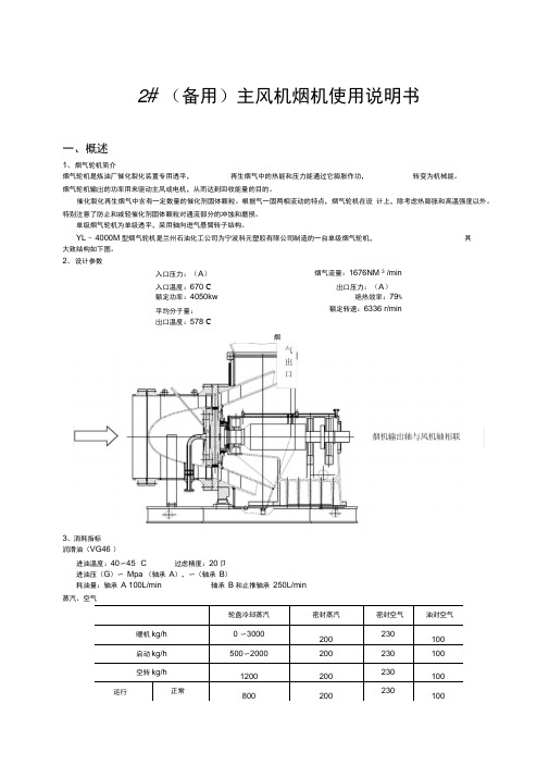
2#(备用)主风机烟机使用说明书一、概述1、烟气轮机简介烟气轮机是炼油厂催化裂化装置专用透平,再生烟气中的热能和压力能通过它膨胀作功,转变为机械能。
烟气轮机输出的功率用来驱动主风或电机,从而达到回收能量的目的。
催化裂化再生烟气中含有一定数量的催化剂固体颗粒。
根据气—固两相流动的特点,烟气轮机在设计上,除考虑热膨胀和高温强度以外。
特别注意了防止和减轻催化剂固体颗粒对通流部分的冲蚀和磨损。
单级烟气轮机为单级透平,采用轴向进气悬臂转子结构。
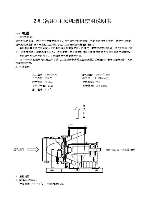
YL -4000M 型烟气轮机是兰州石油化工公司为宁波科元塑胶有限公司制造的一台单级烟气轮机,其大致结构如下图。
2、设计参数入口压力:0.19Mpa(A) 烟气流量:1676NM 3 /min入口温度:670 ℃ 出口压力:0.108Mpa(A) 额定功率:4050kw 绝热效率:79%平均分子量:29.21 额定转速:6336 r/min 出口温度:578 ℃3、消耗指标3.1润滑油(VG46)进油温度:40~45 ℃ 过虑精度:20μ进油压(G)0.147~0.18 Mpa(轴承A),0.08~0.12(轴承B)耗油量:轴承A 100L/min 轴承B和止推轴承250L/min 3.2蒸汽、空气注:密封空气为非净化风、油封空气为净化风。
3.3 支座冷却水(循环水)入口压力(G) 0.4 Mpa入口温度℃ 32耗量kg/h 50004轴承负荷及耗功轴向推力:4.9吨5、YL-4000型烟气轮机空载耗功曲线空载耗功:620kw 启动力矩:1000 N.m 额定转速:6336 rpm 静磨擦阻力矩:380 N.m 6、其它数据6.1烟机轴端冷态找正数据垂直方向(单位mm )水平方向注:安装时,环境温度按20℃计算。
6.2烟机总重量:16000kg6.3最大安装件(底座)重量:6500kg 6.4最大检修重量:1157kg6.5烟机对基础振动最大允许值: 基础顶面振动速度V ≤5mm/s 7、YL -4000M 轮盘温度场冷态5200.56热态二、主要结构及系统1、转子组件转子组件由轮盘,动叶片和主轴等组成。
YL25000B说明书
中国石油宁夏石化公司260万吨/年重油催化裂化装置YL25000B型烟气轮机海南长城机械俄工程有限公司二〇一〇年七月目录1.设计参数…………………………………………………1-32.消耗指标…………………………………………………1-33.轴承负载及耗功………………………………………1-44.启动阻力矩………………………………………………1-45.接口形式与规格……………………………………………1-46.其他参数……………………………………………………1-57.控制要求……………………………………………………1-58.性能曲线…………………………………………………1-69.轴系监测仪表规格型号……………………………………1-71.设计参数1.1.烟气入口压力P o*=0.366 MPa (绝)1.2.烟气进口温度t o=700o C (943o K)1.3.烟气容积流量Q o=4800 Nm3/h1.4.烟气重量流量G o=102.951 Kg/s 1.5.烟气出口压力P z=0.0969 MPa(绝)1.6.烟气透平转速n=4207 r/min1.7.有效输出功率24998kW1.8.绝热效率79%1.9.烟气组成(体积百分比)O2=0.18 %CO= 3.69 %CO2=12.08 %N2=72.74 %H2O= 11.33 %2.消耗指标2.2.蒸汽、空气注:密封空气为非净化风,油封空气为净化风。
2.3.冷却水(循环水)耗量:8000Kg/h(入口压力:0.4MPa(g);入口温度:28℃)4.烟气轮机启动阻力矩空载耗功:kw静摩擦阻力矩:N.m启动阻力矩:N.m额定转速:4207r/min5.接口型式与规格注:带配对法兰。
6.其他参数6.1.烟机总重量:54259kg6.2.最大安装件重量(底座+轴承箱等):~23600kg 6.3.最大检修件重量(进气机壳):5407kg6.4.最大安装件外形尺寸:4370㎜(长)×3870㎜(宽)×2290㎜(高)6.5.烟机对基础振动的允许值:基础顶面振动速度V≤5㎜/s7.监测与控制要求8.性能曲线9.轴系监测仪表规格型号。
燃气轮机发电机组的说明书
燃气轮机发电机组的说明书本说明书旨在为使用者提供有关燃气轮机发电机组的重要信息和操作指南,以确保安全可靠的运行。
一、产品简介
燃气轮机发电机组是一种高效、环保的发电设备,采用燃气发电技术,可广泛应用于发电厂、厂矿企业等场所。
其具有结构简单、体积小、噪音低、响应速度快等特点。
二、技术参数
燃气轮机发电机组的主要技术参数如下:
1.额定功率:XXX 千瓦
2.额定电压:XXX 伏特
3.额定频率:XXX 赫兹
4.燃气消耗率:XXX 立方米/小时
5.轮机效率:XXX %
三、设备安装
1.设备安装前请仔细查看设备包装是否完好,检查设备是否有损坏或松动的部件。
2.设备安装时,需要确保设备的安全稳定,避免设备倾斜或晃动。
3.设备接电时,请先检查电压和频率是否符合设备要求,再进行接线工作。
四、设备使用
1.设备启动前,请检查机组是否润滑良好,发动机是否正常。
2.设备启动后,请密切关注设备运转情况,如发现任何异常状况,请及时停机检查。
3.设备使用过程中,定期进行检查、维护和保养,保证设备运行的可靠性和稳定性。
4.设备使用结束后,请关闭电源并妥善存放设备,及时清洗设备表面和内部。
五、注意事项
1.设备使用过程中请注意安全,禁止使用不合格的电缆、插头等电气配件。
2.设备保养中,禁止使用易燃或腐蚀性物品。
3.禁止对设备进行改装和拆卸。
4.设备使用结束后,请注意及时通风,避免发生安全事故。
以上为本产品使用说明书,请用户严格按照说明操作,确保设备的正常运行和安全。
如有任何疑问或问题,请联系厂家客服人员。
燃气轮机运行与维护说明维护运行轮机燃气轮机说明书运行与维护燃气轮机与维护和运行维护运行和维护

• 1.3.2. 压气机转子 .................................................................................................10 • 1.3.3. 压气机静叶 ...................................................................................................11 • 1.4. 燃烧室............................................................................................................20 • 1.4.1. 概述..............................................................................................................20 • 1.4.2. 燃烧外壳支撑缸,燃烧室和联焰管 ..............................................................21 • 1.4.3.火花塞及火焰探测器 ......................................................................................22 • 1.4.4. 燃料喷嘴 ......................................................................................................24 • 1.4.5.过渡段.............................................................................................................25 • 1.4.6.起动未成排污 ..................................................................................................26 • 1.5 透平 ................................................................................................................26 • 1.5.1. 概述..............................................................................................................26 • 1.5.2. 透平转子 .......................................................................................................27 .
烟气轮机
第六节、烟气轮机停机注意事项
(1)烟气轮机正常停机时,不能快速关闭入口蝶阀,应按 机组的操作要求分阶段逐步关小入口蝶阀,减小负荷,直至 入口蝶阀完全关闭;同时要严格监控机壳的降温速度,当不 能满足要求时,应适当延长停留时间。 (2)关闭入口蝶阀和闸阀后,不能停止盘车,只有当烟气 轮机壳体温度降低到250℃以下时,才能停止盘车,关闭冷 却蒸汽阀门。 (3)只有当轴承温度降低到规程所要求的范围时,才能停 运油泵。 (4)当润滑油压突然下降,且备用泵起动后仍无法恢复正 常、机组超速、机组振动大超标、轴承温度超高时,必须紧 急停机。
3.排气机壳
排气机壳结构
它由进出口法兰、扩压器及壳体组成,为防
止壳体内产生高温热应力,一般壳体厚度较 薄。在壳体外表面焊有加强筋。
4、烟机轴封
转子与排气壳体之间的轴封,采用蒸汽和压缩空气 两组迷宫密封。蒸汽封烟气,压缩空气封蒸汽,且 控制三者之间的压差,保证烟气不外泄。 排气机壳上设置了二组四级不锈钢迷宫气封
导流锥的作用是导引烟气分布均匀,并流向
动静叶片。导流锥里面做成中空,导流锥底 (喇叭口)外径与轮盘外径尺寸应大致相等。 导流锥顶面对着入口烟气,而导流锥底对着 一级轮盘。导流锥内安置一条冷却轮盘蒸汽 管子,该冷却蒸汽径向进入导流锥,再转折 成轴向喷射到一级轮盘上, 进气机壳设置有一条监测一级轮盘温度的温 度计承插管子。该承插管子以约60斜插穿过 导流锥体延伸到一级轮盘前。这样,烟气轮 机工作时,温度计可监测到一级轮盘温度。
第七节、烟机运行故障分析和处理措施
1、轴承温度高 原 因 : 1)轴承润滑油喷嘴孔径小或堵塞 使供油量不足 2)轴承进油温度太高 3)轴承间隙过小 4)润滑油变质或含水份 5)仪表失灵 解决措施: 1)检查孔径是否合格,堵塞物应清理干净 2)清理和更换冷却器 3)增大间隙 4)换油 5)更换温度仪表
PG6581B燃气轮发电机组使 用 维 护 说 明 书
PG6581B燃气轮发电机组使用维护说明书(电起动)南京汽轮电机(集团)有限责任公司编制庄威 04.5.8 校对周亿、余旭翔、杨喻文审核陈智勇 04.5.24 会签标准审查邓爱平 04.5.24 审定杨家强 04.5.25 批准目录1 总则1.1 机组概述1.2 机组的主要技术性能指标1.3 机组对燃料,冷却水及电源的要求1.4 机组结构简要说明2 燃气轮机2.1 概述2.2 进气室及进气分流器2.3 压气机气缸2.4 透平气缸2.5 透平排气缸2.6 排气室2.7 压气机叶片2.8 透平叶片及通流部分2.9 转子组件2.10 轴承2.11 燃烧系统2.12 燃气轮机支承3 燃气轮机的辅机系统3.1 概述3.2 附件传动系统3.3 起动系统和盘车系统3.4 润滑油系统3.5 液压油系统3.6 遮断油(控制油)系统3.7 燃料系统3.8 危险气体检测系统3.9 雾化空气系统3.10 冷却密封空气系统3.11 闭式循环冷却水系统3.12 消防系统3.13 通风和照明系统3.14 压气机清洗系统3.15 压气机抽气处理系统3.16 油气分离系统3.17重油冲洗系统4 发电机总成4.1 发电机4.2 电气设备5 负荷齿轮箱5.1 齿轮箱的主要结构5.2 主要技术性能参数6 控制系统总成6.1概述6.2 SPEEDTRONIC轮机控制盘6.3 发电机控制盘6.4 发电机保护盘6.5 马达控制中心柜6.6 其它电气设备7 进气装置7.1 概述7.2 进气过滤室7.3 进气消音器8 机组的安装和找中心9 机组的运行9.1 机组的运行规范9.2 首次运行前的检查和准备9.3 运行人员职责9.4 总的运行注意事项9.5 正常带负荷运行的准备9.6 运行程序9.7 报警显示系统10 机组的事故停机及故障处理10.1 事故停机10.2 故障处理11 机组的维修和检查1 总则1.1 机组概述PG6581B快装式电站是紧凑的箱装燃气轮发电机组。
烟气轮机说明书
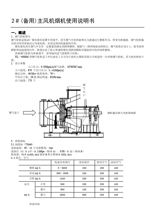
2#(备用)主风机烟机使用说明书一、概述1、烟气轮机简介烟气轮机是炼油厂催化裂化装置专用透平,再生烟气中的热能和压力能通过它膨胀作功,转变为机械能。
烟气轮机输岀的功率用来驱动主风或电机,从而达到回收能量的目的。
催化裂化再生烟气中含有一定数量的催化剂固体颗粒。
根据气一固两相流动的特点,烟气轮机在设计上,除考虑热膨胀和高温强度以外。
特别注意了防止和减轻催化剂固体颗粒对通流部分的冲蚀和磨损。
单级烟气轮机为单级透平,采用轴向进气悬臂转子结构。
YL - 4000M型烟气轮机是兰州石油化工公司为宁波科元塑胶有限公司制造的一台单级烟气轮机,其大致结构如下图。
2、设计参数入口压力:(A)烟气流量:1676NM 3 /min入口温度:670 C岀口压力:(A)额定功率:4050kw绝热效率:79%平均分子量:额定转速:6336 r/min岀口温度:578 C烟3、消耗指标润滑油(VG46 )进油温度:40〜45 °C 过虑精度:20卩进油压(G)〜Mpa (轴承A),〜(轴承B)耗油量:轴承A 100L/min 轴承B和止推轴承250L/min蒸汽、空气支座冷却水(循环水)入口压力(G ) Mpa入口温度C 32 耗量 kg/h 50004轴承负荷及耗功5、 YL — 4000型烟气轮机空载耗功曲线空载耗功:620kw 启动力矩:1000 额定转速:6336 rpm 静磨擦阻力矩:3806、 其它数据烟机轴端冷态找正数据垂直方向 (单位mm )热态冷态水平方向注:安装时,环境温度按 20 C 计算。
烟机总重量:16000kg最大安装件(底座)重量: 6500kg 最大检修重量:1157kg烟机对基础振动最大允许值: 基础顶面振动速度 V < 5mm/s7、YL — 4000M 轮盘温度场二、主要结构及系统1、转子组件转子组件由轮盘,动叶片和主轴等组成。
轮盘与主轴之间以止口定位。
热装后用拉杆螺栓联接,在考 虑到轮盘和拉杆在工作时的热膨胀等因素,拉杆应有足够的预紧力,并采用套筒传扭。
烟气轮机说明书
2#(备用)主风机烟机使用说明书一、概述1、烟气轮机简介烟气轮机是炼油厂催化裂化装置专用透平,再生烟气中的热能和压力能通过它膨胀作功,转变为机械能。
烟气轮机输出的功率用来驱动主风或电机,从而达到回收能量的目的。
催化裂化再生烟气中含有一定数量的催化剂固体颗粒。
根据气—固两相流动的特点,烟气轮机在设计上,除考虑热膨胀和高温强度以外。
特别注意了防止和减轻催化剂固体颗粒对通流部分的冲蚀和磨损。
单级烟气轮机为单级透平,采用轴向进气悬臂转子结构。
YL-4000M型烟气轮机是兰州石油化工公司为宁波科元塑胶有限公司制造的一台单级烟气轮机,其大致结构如下3.3支座冷却水(循环水)入口压力(G)0.4Mpa入口温度℃32耗量kg/h500045、YL66.16.26.36.46.5烟机对基础振动最大允许值:基础顶面振动速度V≤5mm/s7、YL-4000M轮盘温度场二、主要结构及系统1、转子组件转子组件由轮盘,动叶片和主轴等组成。
轮盘与主轴之间以止口定位。
热装后用拉杆螺栓联接,在考虑到轮盘和拉杆在工作时的热膨胀等因素,拉杆应有足够的预紧力,并采用套筒传扭。
轮盘为实心结构,彩高温合金材料模锻并加工而成,轮缘开枞树形叶根槽,用以装入带枞树形叶根的动叶片,动叶片由高温合金精铸或模锻成型,叶身部分喷涂“长城一号”耐磨涂层。
2、进气机壳它主要由进气锥组件、静叶片组件组成,进气机壳为不锈钢焊接件,进气锥体为不锈钢铸件并焊接在进气机壳内,静叶片组件由静叶片、固定镶套和端面梳齿密封环(或蜂窝密封环)组成一个组合件,用螺栓紧固在进气锥端部,在进气壳体上设有可调式挠性辅助支撑。
3、过渡机壳过渡机壳是一衬环。
带有防冲蚀台阶结构。
为减缓催化剂固体颗粒对通流边界的冲蚀和磨损,衬环内壁喷涂耐麿涂层。
4、排气机壳由不锈钢焊接的排气机壳为整体形。
它由进、出口法兰、扩压器及壳体组成整个机壳用进口端法兰上的两个支耳有机体上的两个支耳支承在底座上,在支耳与底座间设有调整垫片,在进口端法兰的两个支耳和底座的支承面之间设置横向导键;在排气机壳的前端和后端设置纵向导键,以保证烟机在热态时壳体膨胀走向合理。
DID09T951型号的提取式烟气机说明书
Instruction manualExtractor hoodDID09T951, DID09T951Ben2Table of contents( Important safety information. . . . . . . . . . . . . . . . 27Environmental protection. . . . . . . . . . . . . . . . . . . 4Saving energy . . . . . . . . . . . . . . . . . . . . . . . . . . . . . . .4Environmentally-friendly disposal . . . . . . . . . . . . . . . . .4Ç Operating modes . . . . . . . . . . . . . . . . . . . . . . . . . 5Exhaust air mode. . . . . . . . . . . . . . . . . . . . . . . . . . . . .5Air recirculation . . . . . . . . . . . . . . . . . . . . . . . . . . . . . .51Operating the appliance . . . . . . . . . . . . . . . . . . . . 5Controls . . . . . . . . . . . . . . . . . . . . . . . . . . . . . . . . . . . .5Setting the fan . . . . . . . . . . . . . . . . . . . . . . . . . . . . . . .6Intensive setting . . . . . . . . . . . . . . . . . . . . . . . . . . . . . .6Intermittent mode. . . . . . . . . . . . . . . . . . . . . . . . . . . . .6Run-on function . . . . . . . . . . . . . . . . . . . . . . . . . . . . . .6Lighting . . . . . . . . . . . . . . . . . . . . . . . . . . . . . . . . . . . .6Saturation signal. . . . . . . . . . . . . . . . . . . . . . . . . . . . . .72Cleaning and maintenance. . . . . . . . . . . . . . . . . . 7Cleaning agents. . . . . . . . . . . . . . . . . . . . . . . . . . . . . .7Cleaning the metal mesh grease filters . . . . . . . . . . . .8Removing metal grease filter . . . . . . . . . . . . . . . . . . . .8Installing the metal mesh grease filter . . . . . . . . . . . . .8Replacing the batteries in the remote control. . . . . . . .83Trouble shooting. . . . . . . . . . . . . . . . . . . . . . . . . . 9After-sales service . . . . . . . . . . . . . . . . . . . . . . . . . . . . 9_ Accessories for air recirculation mode . . . . . . 10Additional information on products, accessories, replacement parts and services can be found at and in the online shop ( Important safety informationR ead these instructions carefully. Only then will you be able to operate your appliance safely and correctly. Retain the instruction manual and installation instructions for future use or for subsequent owners.The appliance can only be used safely if it is correctly installed according to the safety instructions. The installer is responsible for ensuring that the appliance works perfectly at its installation location.This appliance is intended for domestic use and the household environment only. The appliance is not intended for use outside. Do not leave the appliance unattended during operation. The manufacturer is not liable for damage which is caused by improper use or incorrect operation.This appliance is intended for use up to a maximum height of 2000 metres above sea level.This appliance is not intended for use by persons (including children) with reduced physical, sensory or mental capabilities, or lack of experience and knowledge, unless they have been given supervision orinstruction concerning use of the appliance by a person responsible for their safety.Children must not play with, on, or around the appliance. Children must not clean theappliance or carry out general maintenance unless they are at least 8 years old and are being supervised.Keep children below the age of 8 years old at a safe distance from the appliance and power cable.Check the appliance for damage afterunpacking it. Do not connect the appliance if it has been damaged in transport.Only a licensed professional may connect appliances without plugs. Damage caused by incorrect connection is not covered under warranty.:Warning – Danger of suffocation!Packaging material is dangerous to children. Never allow children to play with packaging material.Important safety information en3:Warning – Danger of death!Risk of poisoning from flue gases that are drawn back in.Always ensure adequate fresh air in the room if the appliance is being operated in exhaust air mode at the same time as room air-dependent heat-producing appliance is being operated.Room air-dependent heat-producing appliances (e.g. gas, oil, wood or coal-operated heaters, continuous flow heaters or water heaters) obtain combustion air from the room in which they are installed and discharge the exhaust gases into the open air through an exhaust gas system (e.g. a chimney).In combination with an activated vapourextractor hood, room air is extracted from the kitchen and neighbouring rooms - a partial vacuum is produced if not enough fresh air is supplied. Toxic gases from the chimney or the extraction shaft are sucked back into the living space.■Adequate incoming air must therefore always be ensured.■An incoming/exhaust air wall box alone will not ensure compliance with the limit.Safe operation is possible only when the partial vacuum in the place where the heat-producing appliance is installed does not exceed 4 Pa (0.04 mbar). This can beachieved when the air needed for combustion is able to enter through openings that cannot be sealed, for example in doors, windows, incoming/exhaust air wall boxes or by other technical means.In any case, consult your responsible Master Chimney Sweep. He is able to assess the house's entire ventilation setup and willsuggest the suitable ventilation measures to you.Unrestricted operation is possible if the vapour extractor hood is operated exclusively in the circulating-air mode.:Warning – Risk of fire!■Grease deposits in the grease filter may catch fire.Clean the grease filter at least every 2 months.Never operate the appliance without the grease filter.■Grease deposits in the grease filter may catch fire. Never work with naked flames close to the appliance (e.g. flambéing). Do not install the appliance near a heat-producing appliance for solid fuel (e.g. wood or coal) unless a closed, non-removable cover is available. There must be no flying sparks.■Hot oil and fat can ignite very quickly. Never leave hot fat or oil unattended. Never use water to put out burning oil or fat. Switch off the hotplate. Extinguish flames carefully using a lid, fire blanket or something similar.■When gas burners are in operation without any cookware placed on them, they can build up a lot of heat. A ventilationappliance installed above the cooker may become damaged or catch fire. Onlyoperate the gas burners with cookware on them.■Operating several gas burners at the same time gives rise to a great deal of heat. A ventilation appliance installed above the cooker may become damaged or catch fire. Never operate two gas burnerssimultaneously on the highest flame for longer than 15 minutes. One large burner of more than 5 kW (wok) is equivalent to the power of two gas burners.:Warning – Risk of burns!The accessible parts become very hot when in operation. Never touch hot parts. Keep children at a safe distance.:Warning – Risk of injury!■Components inside the appliance may have sharp edges. Wear protective gloves.■Items placed on the appliance may fall down. Do not place any objects on the appliance.■The light emitted by LED lights is very dazzling, and can damage the eyes (risk group 1). Do not look directly into the switched on LED lights for longer than100 seconds.en Environmental protection4:Warning – Risk of electric shock!■A defective appliance may cause electric shock. Never switch on a defectiveappliance. Unplug the appliance from the mains or switch off the circuit breaker in the fuse box. Contact the after-sales service.■Incorrect repairs are dangerous. Repairs may only be carried out and damaged power cables replaced by one of our trained after-sales technicians. If theappliance is defective, unplug the appliance from the mains or switch off the circuit breaker in the fuse box. Contact the after-sales service.■Do not use any high-pressure cleaners or steam cleaners, which can result in an electric shock.Causes of damageCaution!Risk of damage due to corrosion. Alwaysswitch on the appliance while cooking to avoid condensation. Condensate can produce corrosion damage.Always replace faulty bulbs to prevent the remaining bulbs from overloading.Risk of damage due to ingress of humidity into the electronic circuitry. Never clean operator controls with a wet cloth.Surface damage due to incorrect cleaning. Clean stainless steel surfaces in the direction of the grain only. Do not use any stainless steel cleaners for operator controls.Surface damage due to strong or abrasive cleaning agents. Never use strong and abrasive cleaning agents.Risk of damage from returning condensate. Install the exhaust duct in such a way that it falls away from the appliance slightly (1° slope).7Environmental protectionY our new appliance is particularly energy-efficient. Here you can find tips on how to save even moreenergy when using the appliance, and how to dispose of your appliance properly.Saving energy■Only switch the ventilation on when necessary. You do not need to switch the ventilation on when cooking something for a short time that does not have a strong smell.■Select a fan setting according to what you are cooking.■Switch the ventilation off again after cooking.■Cleaning the grease filter regularly will increase the efficiency of the ventilation.Environmentally-friendly disposalDispose of packaging in an environmentally-friendly manner.This appliance is labelled in accordance with European Directive 2012/19/EU concerning used electrical and electronic appliances (waste electrical and electronic equipment - WEEE). The guideline determines the framework for the return and recycling of used appliances as applicable throughout the EU.Operating modes en5Ç Operating modesE xhaust air modeNote: The air must not be discharged into a flue that is used for exhausting fumes from appliances burning gas or other fuels (not applicable to appliances that only discharge the air back into the room).■Before conveying the exhaust air into a non-functioning smoke or exhaust gas flue, obtain the consent of the heating engineer responsible.■If the exhaust air is conveyed through the outer wall, a telescopic wall box should be used.Air recirculationNote: To bind odours in air recirculation mode, you must install an activated carbon filter. The different options for operating the appliance in air recirculation mode can be found in the brochure. Alternatively, ask your dealer. The required accessories are available from specialist retailers, from customer service or from the Online Shop.1Operating the applianceN otes ■Press the buttons briefly to activate the various functions. The function you are trying to select will not be activated if you hold the button down for too long.■The appliance will emit a beep to confirm that a button has been pressed.Note: Switch on the extractor hood when you startcooking and switch it off again several minutes after you have finished cooking. This is the most effective way of removing the kitchen fumes.ControlsUse the remote control to set and adjust the various different functions of your appliance.Note: The remote control requires 23AE 12 V batteries. For information on how to insert the batteries, refer to the section entitled ~ "Cleaning and maintenance" on page 7Note: Heat and penetrating moisture may damage the remote control. Never expose the remote control to intense heat or moisture.Remote controlOperating buttons Connecting the remote control to the appliance If the appliance cannot be operated with the remote control, e.g. after the battery has been changed, the connection between the remote control and the appliance must be re-established.1.Press and hold the @ button.2.Attach the appliance to the mains voltage.A long audible signal sounds. The remote control has been connected to the appliance.Note: If no audible signal sounds within 30 seconds, repeat this procedure.The air which is drawn in is cleaned by the grease filters and conveyed to the exterior by a pipe system.The air which is drawn in is cleaned by the grease filters and an activatedcarbon filter, and is conveyed back intothe kitchen.en Operating the appliance 6Extractor hood's control panelOperating buttons Setting the fanNote: Always adjust the setting according to the current conditions. To eliminate strong cooking smells, select a high fan setting.Switching on1.Press the @ button.The fan will start at fan setting ƒ.2.Press the @ or A button to set a different fan setting.Note: The appliance has three fan settings and an intensive setting. To set the lowest setting,press A once. If you press it more than once, the appliance will switch off again.Switching offPress and hold the A button until the appliance switches off.or press the $ button.Intensive settingYou can use the intensive setting if there is a large build-up of odours and fumes/vapours.Press and hold the @ button until ˜ appears in the fan settings display .Note: Intensive mode runs for four minutes. Once this time has elapsed, the appliance will switch back to fan setting ƒ.Intermittent modeIntermittent mode automatically switches on theextractor hood for 10 minutes every hour. The function switches itself off again after 24 hours.This function can be activated from the control panel or using the remote control.Note: If intensive mode or the run-on function has been activated, the intermittent function will not be available.Switching on intermittent mode from the control panel1.Press the $ and @ buttons at the same time. ‚ willappear on the display.2.Press the @ or A button to set a different fan setting.3.Press the $ and @ buttons at the same time to confirm the fan setting for intermittent mode.Switching on intermittent mode using the remote control1.Press the H button. ‚ will appear on the display.2.Press the @ or A button to set a different fan setting.3.Press the H button to confirm the fan setting forintermittent modeNote: Pressing any of the buttons (except the button for the light) will deactivate intermittent mode.Run-on functionThe run-on function allows the extractor hood to continue running for a few minutes after it has been switched off. This eliminates any remaining cooking smells. The extractor hood will then switch itself off automatically.Switching onNote: If intensive mode has been activated, the run-on function will not be available.Press the I + button on the control panel or the y button on the remote control.The fan will run for 10 minutes at setting ‚ and a dot will flash on the display during this time. Then the fan will switch itself off automatically.Switching offPress the I * or $ button on the control panel or the + button on the remote control for the extractor hood.This will deactivate the run-on function immediately.LightingPress the A button on the control panel or the B button on the remote control.Cleaning and maintenance en7Saturation signalThe following will happen when the filters are saturated:■The ª symbol appears in the display: Clean the metal grease filter■The ’ symbol appears in the display and a signal sounds: Replace the activated charcoal filterSee the "CleanAir air recirculation module" printed supplement or the section entitled ~ "Cleaning and maintenance" on page 7Resetting the saturation signalWhen the fan is switched off, the signal is also switched off.The relevant filter(s) should be cleaned now if you have not already done so.Switching over the appliance to air recirculation1.Switch off the appliance.2.Press the $ and I * buttons on the control panelat the same time until the ’ indicator lights up.Then release the buttons.The ’ indicator will go out shortly afterwards. Theelectronic controller has now been switched over to air recirculation mode.Switching over the appliance to air extraction Note: The default setting is air extraction mode.1.Switch off the appliance.2.Press the $ and I * buttons on the control panelat the same time until the ª indicator lights up.Then release the buttons.The ª indicator will go out shortly afterwards. Theelectronic controller has now been switched over to air extraction mode.2Cleaning and maintenance:Warning – Risk of burns!The appliance becomes hot during operation. Allow the appliance to cool down before cleaning.:Warning – Risk of electric shock!Penetrating moisture may result in an electric shock. Clean the appliance using a damp cloth only. Before cleaning, pull out the mains plug or switch off the circuit breaker in the fuse box.:Warning – Risk of electric shock! Do not use any high-pressure cleaners or steam cleaners, which can result in an electric shock.:Warning – Risk of injury!Components inside the appliance may have sharp edges. Wear protective gloves.Cleaning agentsTo ensure that the different surfaces are not damaged by using the wrong cleaning agent, observe theinformation in the table. Do not use any of the following:■Harsh or abrasive cleaning agents,■Cleaning agents with a high alcohol content,■Hard scouring pads or cleaning sponges,■High-pressure cleaners or steam cleaners.Wash new sponge cloths thoroughly before use.Follow all instructions and warnings included with the cleaning agents.en Cleaning and maintenance8Cleaning the metal mesh grease filtersThese instructions apply to several appliance variants. It is possible that individual features are described which do not apply to your appliance.:Warning – Risk of fire!Grease deposits in the grease filter may catch fire.Clean the grease filter at least every 2 months.Never operate the appliance without the grease filter.Notes ■Do not use any aggressive, acidic or alkaline cleaning agents.■When cleaning the metal mesh grease filters, also clean the holder for the metal mesh grease filters in the appliance using a damp cloth.■The metal mesh grease filters can be cleaned in the dishwasher or by hand.By hand:Note: You can use a special grease solvent for stubborn dirt. It can be ordered via the Online Shop.■Soak the metal mesh grease filters in a hot soapy solution.■Clean the filters with a brush and then rinse them thoroughly.■Leave the metal mesh grease filters to drain.In the dishwasher:Note: If the metal mesh grease filters are cleaned in the dishwasher, slight discolouration may occur. This has no effect on the function of the metal mesh grease filters.■Do not clean heavily soiled metal mesh grease filters together with utensils.■Place the metal mesh grease filters loosely in the dishwasher. The metal mesh grease filters must not be wedged in.Removing metal grease filter1.Open the filter cover by pulling it downwards.Notes–The filter cover is heavy. Hold the filter cover with both hands.–Open the filter cover slowly and carefully.3.Take the metal grease filter out of the holder.Note: Fat may accumulate in the bottom of the metal grease filter. Hold the metal grease filter level to prevent fat from dripping out.4.Clean the appliance from the inside.5.Clean the metal grease filter and let it dry before refitting it.Installing the metal mesh grease filter1.Insert metal grease filter.While doing this, place your other hand under the metal grease filter.2.Fold up metal grease filter and engage the lock.3.Close the filter cover upwards.Note: Ensure that the filter cover lock engages correctly.Replacing the batteries in the remote control1.Undo screws.2.Remove cover.3.Remove the batteries.4.Correctly insert the new batteries (23AE 12 V).5.Dispose of flat or faulty batteries according to local regulations.Note: Do not dispose of batteries in general householdwaste.Trouble shooting en93Trouble shootingM alfunctions often have simple explanations. Please read the following notes before calling the after-sales service.:WarningRisk of electric shock!Incorrect repairs are dangerous. Repairs may only be carried out and damaged power cables replaced by one of our trained after-sales technicians. If theappliance is defective, unplug the appliance from the mains or switch off the circuit breaker in the fuse box. Contact the after-sales service.LED lightsDefective LED lights must only be replaced by the manufacturer, their customer service department or a licensed technician (electrician).Malfunction tableAfter-sales serviceOur after-sales service is there for you if your appliance needs to be repaired. We will always find the right solution in order to avoid unnecessary visits from a service technician.When calling us, please give the product number (E no.) and the production number (FD no.) so that we can provide you with the correct advice. The rating plate with these numbers can be found inside the appliance (remove the metal mesh grease filter to gain access).You can make a note of the numbers of your appliance and the telephone number of the after-sales service in the space below to save time should it be required.Please be aware that a visit by an after-sales engineer will be charged if a problem turns out to be the result of operator error, even during the warranty period.Please find the contact data of all countries in the enclosed customer service list.To book an engineer visit and product advice Rely on the professionalism of the manufacturer. You can therefore be sure that the repair is carried out by trained service technicians who carry original spare parts for your appliances.GB ***********Calls charged at local or mobile rate.IE 01450 26550.03 € per minute at peak. Off peak 0.0088 € per minute.en Accessories for air recirculation mode10_ Accessories for air recirculation mode(not supplied)6Robert Bosch Hausgeräte GmbH Carl-Wery-Straße 3481739 München,GERMANY *9001289769*9001289769970412。
YL-11000F型 烟气轮机 202-EP-101(说明书)
A1档案号 BCRE-2265/A1 0说 明 书设计阶段 初步资料版本AFC共 7 页 第 1 页审核 校 对 编 制 版 次 0 日 期 2011.12YL-11000F 型烟气轮机编 制 丁 勤 张家灿校 对 王自球审 核 冀 江共7 页第2页目录1.概述 (3)2.设计要求和设计参数 (3)3.消耗指标 (4)4.轴承负荷及耗功 (4)5.空载耗功曲线 (5)6.其它参数 (6)7.轮盘温度场 (7)共7 页第3页1.概述YL-11000F型烟气轮机用于河南丰利石化有限公司2万吨/年丙烯原料生产装置烟气轮机-主风机能量回收机组中。
该烟机为轴向进气,垂直向上排气。
转子结构为单级轮盘、悬臂结构。
2.设计参数变工况1 变工况2 入口压力: 0.29MPa(a) 0.27 0.31烟气流量: 2728Nm3/min 2539 2917入口温度: 670 °C 670 670出口压力: 0.106MPa(a) 0.106 0.110额定功率: 11000kw绝热效率:79%平均分子量:29.2额定转速: 5800r/min出口温度: 515°C3.消耗指标3.1. 润滑油(VG46)进油温度:45±2℃过滤精度10μ进油压(表):0.147~0.18MPa(轴承A),0.08~0.12MPa(轴承B)耗油量:轴承A1001/min轴承B和止推轴承250l/min3.2. 蒸汽、空气共7 页第4页轮盘冷却蒸汽密封蒸汽密封空气油封空气暖机Kg/h ~3000 200 230 100 启动Kg/h 500~2000 200 230 100 空转Kg/h 1200 200 230 100运行Kg/h 正常800 200 230 100 最小500 180 200 100 最大2000 500 280 100管网压力Mpa(A) 1.0 1.0 0.6 0.6 管网温度℃250 25040 40注:密封空气、油封空气为净化风。
12第12章烟气轮机20060811
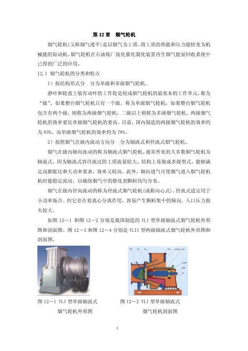
气轮机最基本的工作单元。它主要由一列静叶片和一列动叶片组成。图 12-5
表示烟机某一级的热力参数变化情况,静叶片前截面(即级进口截面)用 0-0 表
示,静叶片和动叶片之间的截面用 1-1 表示,而动叶片后截面(即级出口截面)
用 2-2 表示。这三个截面通常称为级的特征截面,其气流参数分别注以下标 0、
带有固体微粒的气流进入烟气轮机时,在静叶和动叶流道内,细小微粒(一 般指小于 5μm 的颗粒)基本上随气流一起运动,造成比单纯气流有较大的粘性作 用和粘性损失,另外,一些较大的颗粒由于惯性较大,速度滞后于气体的速度, 其速度三角形与气体的速度三角形有明显的差别,如图 12-6 所示。
图 12-6 微粒大小对动叶前、 图 12-7 不同粒度的微粒在
(8)输出功率(或称回收功率)N。
*
N=GH 0 η
kw
输出功率估算时,效率η选取:单级烟气轮机取 0.78,两级烟气轮机取 0.83,
多级烟气轮机取 0.85。
图 12-10 某烟气轮机的性能曲线 图 12-10 为某台烟气轮机的性能曲线,它反映输出功率与烟气进口压力、 温度、质量流量间的关系。 12.5 我国 YLⅡ烟气轮机的主要结构与系统的组成 现以我国 YLⅡ10000B 型烟气轮机为例,说明烟气轮机的主要结构与系统的 组成概况。 YL10000II 型烟气轮机为双支点悬臂式烟气轮机。它主要由底座、轴承箱、 排气机壳、过渡机壳、进气机壳、转子六大部分组成。 1. 转子组件 转子总成主要由一、二级轮盘和一、二级动叶片及主轴等组成。一、二级轮 盘之间和两级轮盘与主轴之间,以止口定位,并热装在轴端。在考虑到轮盘和拉 紧螺栓工作时的热膨胀变形等因素后,由具有足够预紧力的拉紧螺栓将轮盘和主 轴联结固定,并用套筒传递扭矩。
烟气轮机说明书
2#(备用)主风机烟机使用说明书一、概述1、烟气轮机简介烟气轮机是炼油厂催化裂化装置专用透平,再生烟气中的热能和压力能通过它膨胀作功,转变为机械能。
烟气轮机输出的功率用来驱动主风或电机,从而达到回收能量的目的。
催化裂化再生烟气中含有一定数量的催化剂固体颗粒。
根据气—固两相流动的特点,烟气轮机在设计上,除考虑热膨胀和高温强度以外。
特别注意了防止和减轻催化剂固体颗粒对通流部分的冲蚀和磨损。
单级烟气轮机为单级透平,采用轴向进气悬臂转子结构。
YL-4000M型烟气轮机是兰州石油化工公司为宁波科元塑胶有限公司制造的一台单级烟气轮机,其大致结构如下3.3支座冷却水(循环水)入口压力(G)0.4Mpa入口温度℃32耗量kg/h500045、YL66.16.26.36.46.5烟机对基础振动最大允许值:基础顶面振动速度V≤5mm/s7、YL-4000M轮盘温度场二、主要结构及系统1、转子组件转子组件由轮盘,动叶片和主轴等组成。
轮盘与主轴之间以止口定位。
热装后用拉杆螺栓联接,在考虑到轮盘和拉杆在工作时的热膨胀等因素,拉杆应有足够的预紧力,并采用套筒传扭。
轮盘为实心结构,彩高温合金材料模锻并加工而成,轮缘开枞树形叶根槽,用以装入带枞树形叶根的动叶片,动叶片由高温合金精铸或模锻成型,叶身部分喷涂“长城一号”耐磨涂层。
2、进气机壳它主要由进气锥组件、静叶片组件组成,进气机壳为不锈钢焊接件,进气锥体为不锈钢铸件并焊接在进气机壳内,静叶片组件由静叶片、固定镶套和端面梳齿密封环(或蜂窝密封环)组成一个组合件,用螺栓紧固在进气锥端部,在进气壳体上设有可调式挠性辅助支撑。
3、过渡机壳过渡机壳是一衬环。
带有防冲蚀台阶结构。
为减缓催化剂固体颗粒对通流边界的冲蚀和磨损,衬环内壁喷涂耐麿涂层。
4、排气机壳由不锈钢焊接的排气机壳为整体形。
它由进、出口法兰、扩压器及壳体组成整个机壳用进口端法兰上的两个支耳有机体上的两个支耳支承在底座上,在支耳与底座间设有调整垫片,在进口端法兰的两个支耳和底座的支承面之间设置横向导键;在排气机壳的前端和后端设置纵向导键,以保证烟机在热态时壳体膨胀走向合理。
烟气轮机ppt课件
(3)旋风系统故障造成分离效率下降,是造成烟气中催化剂 粉尘浓度过高从而导致烟机内催化剂结垢的主要原因。特别是 卧管式三旋存在着单管负荷分配不均,容易造成部分分离单管 负荷过大而发生单管内的结垢进而发生单管堵死,导致三旋的 分离效果下降。
(22)径向轴承类型
四油叶滑动轴承
(23)止推轴承类型
金氏伯利轴承
36
第二节烟气轮机级的工作原理
一、级的工作过程
37
38
39
40
单、多级烟气轮机的优点
多级烟气轮机的特点在于回收效率高,合理 的设计可使效率达到88%左右,但是其缺点是 结构复杂、零件数量多,特别是增加了转动零 件,导致设计制造成本高、可靠性下降.
单级的特点是结构简单、设计制造成本低、 可靠性高,但回收效率不理想,特别是高落 压比情况下,单级效率在70%左右。现有的烟 气轮机工作落压比在“3”左右,原单级结构 不能完全有效回收烟气压力能.
41
第三节烟气在级内流道中的流 动规律与对叶片磨损的影响
一、烟气在流道内的流动规律 带有固体微粒的气流进入烟气轮机时,在静叶和 动叶流道内除极细小微粒(一般指小于5μ的颗粒) 基本上随气流一起运动,造成比单纯气流有较大 的粘性作用和粘性损失外,一些较大的颗粒由于 惯性较大。
44
微粒速度取决于气体速度和粉尘颗 粒大小。因此,在设计上一般靠控制气 体速度来限制微粒速度,以减少叶片的 磨损。
PG6581B燃气轮发电机组使 用 维 护 说 明 书
PG6581B燃气轮发电机组使用维护说明书(电起动)南京汽轮电机(集团)有限责任公司代号R040.01/02代替PG6581B燃气轮发电机组使用维护说明书(电起动)编制何奎2004.2.18校对陈智勇曾凤清朱新铭周忆审核杨家强2004.2.24会签标准审查邓爱平2004.2.24审定李庆松2004.2.25批准目录1 总则1.1 机组概述1.2 机组的主要技术性能指标1.3 机组对燃料,冷却水及电源的要求1.4 机组结构简要说明2 燃气轮机2.1 概述2.2 进气室及进气分流器2.3 压气机气缸2.4 透平气缸2.5 透平排气缸2.6 排气室2.7 压气机叶片2.8 透平叶片及通流部分2.9 转子组件2.10 轴承2.11 燃烧系统2.12 燃气轮机支承3 燃气轮机的辅机系统3.1 概述3.2 附件传动系统3.3 起动系统和盘车系统3.4 润滑油系统3.5 液压油系统3.6 遮断油(控制油)系统3.7 燃料系统3.8 危险气体检测系统3.9 雾化空气系统3.10 冷却密封空气系统3.11 开式循环冷却水系统3.12 消防系统3.13 通风和照明系统3.14 压气机与透平清洗系统3.15 压气机抽气处理系统3.16 油气分离系统3.17 重油冲洗系统4 发电机总成4.1 发电机4.2 电气设备5 负荷齿轮箱5.1 齿轮箱的主要结构5.2 主要技术性能参数6 控制系统总成6.1概述6.2 SPEEDTRONIC轮机控制盘6.3 发电机控制盘6.4 发电机保护盘6.5 马达控制中心柜6.6 其它电气设备7 进气装置7.1 概述7.2 进气过滤室7.3 进气消音器8 机组的安装和找中心9 机组的运行9.1 机组的运行规范9.2 首次运行前的检查和准备9.3 运行人员职责9.4 总的运行注意事项9.5 正常带负荷运行的准备9.6 运行程序9.7 报警显示系统10 机组的事故停机及故障处理10.1 事故停机10.2 故障处理11 机组的维修和检查1 总则1.1 机组概述PG6581B快装式电站是紧凑的箱装燃气轮发电机组.它的主体部分由控制室,燃气轮机,发电机三大部分组成.其中燃气轮机及控制室分别装设于大型焊接底盘上.为了户外安装及隔音,隔热的需要,在底盘上装有全天候罩壳.发电机不设置底盘,直接安装在使用现场的基础上.为了传动上的需要,在燃气轮机与发电机之间装有负荷齿轮箱.负荷齿轮箱装在独立的底盘上.根据户外安装的要求,在齿轮箱及发电机上加装了罩壳.机组可以单独运行,作基本负荷或尖峰负荷发电之用,也可以和余热锅炉及汽轮机等设备一起,组成联合循环电站.机组体积紧凑,占地面积小,辅助设备少.电站设备的程序控制,检测保护全部采用电子电路,操作运行的自动化程度较高,需要的运行人员较少.1.2 机组的主要技术性能指标1.2.1 ISO状态下机组的额定功率ISO状态(大气温度15℃,大气压力1.013×10⁵Pa,相对湿度60%). 燃机转速5163r/min,进气压力损失101.6mm水柱,排气压力损失63.5mm水柱,并且使用的气体燃料符合规范GEI-41040F,液体燃料符合GEI-41047H。
典型化工机器基本(烟气轮机)

黄斌
二级导流叶环组件主要由二级导流叶环体、二级静叶片、 迷宫密封、销钉组成。二级导流叶环体内径锥度为11°47´24 〞,开有T型二级静叶环固定槽,二级静叶片靠外圆止口单片 用T型叶根固定在固定槽内。并用销钉对二级静叶片定位。T型 叶根与固定槽的配合径向间隙和侧间隙为0.02〜0.1mm。以便 于安装和静叶片热膨胀。
下左图和下右图分别是分别是我国制造的 YLII型两级轴流
式烟气轮机剖面图和 YLI型单级轴流式烟气轮机剖面图。
黄斌
二、烟气轮机的主要结构与系统的组成 以我国YLⅡ10000B型烟气轮机为例,来说明烟气轮机的主
要结构与系统的组成概况。 YLⅡ10000B型烟气轮机为双支点悬臂式烟气轮机。它主要
由底座、轴承箱、排气 1
黄斌
2、按照烟气在级内流动方向分为轴流式和径流式烟气轮机。 烟气在级 轴向流动方式的称为轴流式烟气轮机。通常所见
的大多数烟气轮机为轴流式,因为轴流式容许流过较大的工质 流量,结构上易做成多级型式,能够满足高膨胀比和大功率要 求,效率又较高。此外,轴向进气可使烟气进入烟机时能稳定 流动,以确保烟气中的催化剂颗粒均匀分布。
为了减少轮盘重量和冷却二级轮盘的需要,在一二级轮盘 外缘之间对接处,做成中空结构,形成了空腔。
转子的设计在结构上采取了防止催化剂在一二级轮盘之间 堆积的措施。即在一、二级轮盘外凸缘对接处之间,保留有 5mm间隙的蒸汽喷射孔,务必保证空腔内的蒸汽压力大于一二 级轮盘外侧的烟气压力。以阻止烟气粉尘落入空腔内。即使烟 气粉尘落入一二级轮盘之间内空腔,通过转子的转动,可把粉 尘从5mm间隙中抛出来。防止因催化剂在内凹面中堆积的不平 衡而引起转子振动。
4.烟气轮机
5) 烟机出口水封罐装水,罐前放空阀打开。 6) 烟机全部切出系统,加大烟机轮盘的冷却蒸汽,当烟机壳 体温度降到250℃以下,可以适当关小轮盘的冷却蒸汽。
7) 联系反应岗位,逐步将轴流压缩机切出系统,把可调静叶 关至最小位置,主风出口放空阀缓慢打开,出口电动阀同步 缓慢关闭。
8) 用流量控制器ETS302慢慢降低透平的负荷,直至透平的 蒸汽入口流量为25t/h,流量控制ETS302自动切换至速度控 制ETS301。 9) 联系各调度后,通知配电间、班长、按PB手动停机按钮, 机组降速。
烟气轮机
第一节概述
一、烟气轮机的应用 烟气轮机在石油炼厂流化催化裂化装置再生 烟气能量回收系统中已得到广泛的应用。
部 件 装 配 图
二、烟气轮机的结构型式与组成
烟气轮机的结构除要满足工质能量转换的要
求外,还应适应高温、高速和高速催化剂粉尘气 流冲蚀的工艺要求。
1.转子组件
减缓烟机结垢措施
(3)提高旋风分离器效率,降低烟机入口粉尘浓度。 正常操作时旋风分离器入口线速控制在设计范围内, 确保旋风分离器效率。与设计单位沟通,改大灰斗及 料腿。 对临界喷咀改造,临界喷咀泄气按5%靠,避免操作波 动时超负荷导致三旋单管堵塞。 对三旋单管或单管排尘口改造,避免操作波动时超负 荷导致三旋单管堵塞。 加强三旋压废剂管理,保证三旋排尘正常。
燃气轮机运行手册-中英文-提交07-27讲解

燃气轮机运行手册-中英文-提交07-27讲解CSPC南海石化项目CSPC NANHAI PETROCHEMICALS PROJECT GTG 运行手册GTG Operation Manual运行手册:OM-8130-8160-0003Operation Manual OM-8130-8160-0003山东电力基本建设总公司SEPCO Electric Power Construction Corporation 修改记录目录CONTENT1定义说明Definition (5)2BB燃料系统BB Fuel system (6)2.1 系统投入条件Conditions for Putting System in Service (6)2.2 系统设备规范System Equipment Specification (6)2.3 系统介绍和控制描述Description of System and Control (7)2.4 系统阀门检查卡Check Card for System and Valve (8)2.5 系统投入前检查Checks Before Putting System in Service (14)2.6 系统投入System In Service (14)2.7 参考图纸Reference Drawings (16)3燃机运行Operation for GT (16)3.1 燃气轮机概述Outline of Gas Turbine (16)3.2 技术规范Technical Specification (16)3.3 燃气轮机热力工作过程Thermodynamic Process in GT Operation (17) 3.4 辅助系统设备规范Auxiliary System Equipment (17)3.5 系统介绍System Introduction (21)3.6 热工保护及连锁Instrumented Protection and Interlocks (32) 3.7 燃气轮机启动阀门操作卡Valve Check Sheet for GT Starting Up (34)3.8 燃气轮机的启动GT Start Up (37)3.9 燃气轮机的停止GT Shut Off (55)3.10 机组正常运行和日常维护Routine Operation/Maintenance of GT Set (58) 3.11 日常操作Routine Operation (60)3.12 运行中抄表内容Reading Record During Operation (72)4 HSE (73)2 BB燃料部分BB fuel mannual2.1 系统投入条件:Conditions for Putting System in ServiceFLARE COLLECTION 投入运行.Put Flare Collection in service中压蒸汽可以供给本系统用汽.Provide MP steam to this system低压蒸汽可以供给本系统用汽.Provide LP steam to this system中压蒸汽凝结水收集系统投入运行.Put MP steam condensate collection in operation低压蒸汽凝结水收集系统投入运行.Put LP steam condensate collection in operation仪用空气系统运行正常.Make sure instrument air system in normal operationGT控制油系统运行正常.Make sure GT control oil system in normal operationGT压力油系统运行正常。
第7章 烟气轮机v300
广东石油化工学院
化工过程机器
广东石油化工学院
烟气轮机的发展
化工过程机器
➢兰州炼化总厂机械厂生产的第一台YLII型双级烟气 轮机(YLII6000型大功率双级烟气轮机)于1982年11 月11日在兰州炼油厂投入运行。
➢以后,烟气轮机陆续发展到各主要炼厂,最大功率 可达2×10⁴KW。
➢国内西安航空发动机厂及哈尔滨汽轮机厂也可以生 产烟气轮机。
➢提高材料的性能:为保证烟气轮机长周期连续运行, 烟机部件的材料不仅要具有良好的高温机械性能,还 应有良好的抗低周疲劳性能和高温抗腐蚀性能。烟气 轮机主要部件的设计寿命通常为100,000小时。随着 新材料、新喷涂技术的出现,烟气轮机叶片从初期1 年左右寿命延长到3~5年。
广东石油化工学院
化工过程机器
广东石油化工学院
§7.1 概述
化工过程机器
➢烟气轮机(又称烟气透平)是以烟气为工质,将工质 的热能和压力能转变为机械能的原动机。
➢烟气轮机在石油炼厂流化催化裂化装置再生烟气能 量回收系统中已得到广泛的应用,是应用于石油加工 企业催化裂化装置的关键节能设备。
➢烟气轮机以生产过程中产生的高温废烟气为介质, 膨胀输出轴功,驱动主风机或带动发电机发电,具有 显著的节能和环保效益。
广东石油化工学院
化工过程机器
广东石油化工学院
烟气轮机的发展
化工过程机器
➢美国在50年代初就着手研究能量回收技术,并于 1963年开始工业化。
➢近年来,由于再生器工艺参数的提高和重油、渣油 催化裂化工艺的开发,在装置上增设能量回收系统日 益普遍。
➢中国目前拥有催化裂化(FCC)装置规模约1.2亿吨, 大约160套装置,
➢工质中含有腐蚀性物质CO、CO2、SOX、NOX等,对 金属材料有腐蚀作用。
出烟鼓轮数据说明书
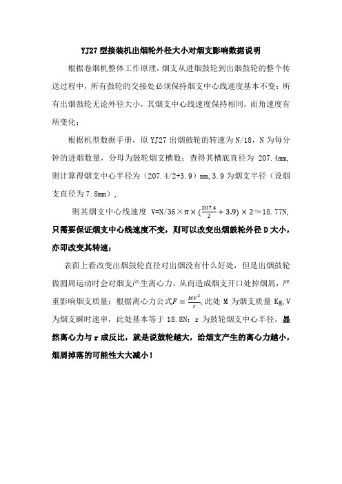
YJ27型接装机出烟轮外径大小对烟支影响数据说明根据卷烟机整体工作原理,烟支从进烟鼓轮到出烟鼓轮的整个传送过程中,所有鼓轮的交接处必须保持烟支中心线速度基本不变;所有出烟鼓轮无论外径大小,其烟支中心线速度保持相同,而角速度有所变化;
根据机型数据手册,原YJ27出烟鼓轮的转速为N/18,N为每分钟的进烟数量,分母为鼓轮烟支槽数;查得其槽底直径为207.4mm,则计算得烟支中心半径为(207.4/2+3.9)mm,3.9为烟支半径(设烟支直径为7.8mm),
则其烟支中心线速度V=N/36×π×(207.4
2
+3.9)×2≈18.77N,只需要保证烟支中心线速度不变,则可以改变出烟鼓轮外径D大小,亦即改变其转速;
表面上看改变出烟鼓轮直径对出烟没有什么好处,但是出烟鼓轮做圆周运动时会对烟支产生离心力,从而造成烟支开口处掉烟屑,严
重影响烟支质量;根据离心力公式F=MV 2
r
,此处M为烟支质量Kg,V 为烟支瞬时速率,此处基本等于18.8N;r为鼓轮烟支中心半径,显然离心力与r成反比,就是说鼓轮越大,给烟支产生的离心力越小,烟屑掉落的可能性大大减小!。
- 1、下载文档前请自行甄别文档内容的完整性,平台不提供额外的编辑、内容补充、找答案等附加服务。
- 2、"仅部分预览"的文档,不可在线预览部分如存在完整性等问题,可反馈申请退款(可完整预览的文档不适用该条件!)。
- 3、如文档侵犯您的权益,请联系客服反馈,我们会尽快为您处理(人工客服工作时间:9:00-18:30)。
2#(备用)主风机烟机使用说明书一、概述1、烟气轮机简介烟气轮机是炼油厂催化裂化装置专用透平,再生烟气中的热能和压力能通过它膨胀作功,转变为机械能。
烟气轮机输出的功率用来驱动主风或电机,从而达到回收能量的目的。
催化裂化再生烟气中含有一定数量的催化剂固体颗粒。
根据气—固两相流动的特点,烟气轮机在设计上,除考虑热膨胀和高温强度以外。
特别注意了防止和减轻催化剂固体颗粒对通流部分的冲蚀和磨损。
单级烟气轮机为单级透平,采用轴向进气悬臂转子结构。
YL -4000M 型烟气轮机是兰州石油化工公司为宁波科元塑胶有限公司制造的一台单级烟气轮机,其大致结构如下图。
2、设计参数入口压力:0.19Mpa(A) 烟气流量:1676NM 3 /min入口温度:670 ℃ 出口压力:0.108Mpa(A) 额定功率:4050kw 绝热效率:79%平均分子量:29.21 额定转速:6336 r/min 出口温度:578 ℃3、消耗指标3.1润滑油(VG46)进油温度:40~45 ℃ 过虑精度:20μ 进油压(G )0.147~0.18 Mpa (轴承A ),0.08~0.12(轴承B ) 耗油量:轴承A 100L/min 轴承B 和止推轴承250L/min 3.2注:密封空气为非净化风、油封空气为净化风。
3.3 支座冷却水(循环水)入口压力(G) 0.4 Mpa入口温度℃ 32耗量kg/h 50004轴承负荷及耗功轴向推力:4.9吨5、YL-4000型烟气轮机空载耗功曲线空载耗功:620kw启动力矩:1000 N.m额定转速:6336 rpm静磨擦阻力矩:380 N.m6、其它数据6.1烟机轴端冷态找正数据注:安装时,环境温度按20℃计算。
6.2烟机总重量:16000kg6.3最大安装件(底座)重量:6500kg 6.4最大检修重量:1157kg6.5烟机对基础振动最大允许值:基础顶面振动速度V≤5mm/s7、YL-4000M轮盘温度场二、主要结构及系统1、转子组件转子组件由轮盘,动叶片和主轴等组成。
轮盘与主轴之间以止口定位。
热装后用拉杆螺栓联接,在考虑到轮盘和拉杆在工作时的热膨胀等因素,拉杆应有足够的预紧力,并采用套筒传扭。
轮盘为实心结构,彩高温合金材料模锻并加工而成,轮缘开枞树形叶根槽,用以装入带枞树形叶根的动叶片,动叶片由高温合金精铸或模锻成型,叶身部分喷涂“长城一号”耐磨涂层。
2、进气机壳它主要由进气锥组件、静叶片组件组成,进气机壳为不锈钢焊接件,进气锥体为不锈钢铸件并焊接在进气机壳内,静叶片组件由静叶片、固定镶套和端面梳齿密封环(或蜂窝密封环)组成一个组合件,用螺栓紧固在进气锥端部,在进气壳体上设有可调式挠性辅助支撑。
3、过渡机壳过渡机壳是一衬环。
带有防冲蚀台阶结构。
为减缓催化剂固体颗粒对通流边界的冲蚀和磨损,衬环内壁喷涂耐麿涂层。
4、排气机壳由不锈钢焊接的排气机壳为整体形。
它由进、出口法兰、扩压器及壳体组成整个机壳用进口端法兰上的两个支耳有机体上的两个支耳支承在底座上,在支耳与底座间设有调整垫片,在进口端法兰的两个支耳和底座的支承面之间设置横向导键;在排气机壳的前端和后端设置纵向导键,以保证烟机在热态时壳体膨胀走向合理。
5、轴承箱及轴承轴承箱系水平剖分结构,由箱体和箱盖组成,均为铸钢件。
其上装有轴承和油封及测转速、测轴振动探头、并接有轴承润滑油进出口管线。
轴承部件由两组径向轴承和一组止推轴承组成。
固定在轴承箱内。
径向轴承为四油叶滑动轴承或可倾瓦轴承,主止推轴承为八块的金氏伯里节油轴承或米契尔轴承。
在装配时,转子相对于机壳的对中与定位通过轴承箱底面下的调整垫片来调节,用螺栓和定位销固定在底座上。
6、轴封气路系统A、轴密封气路系统轴密封采用蒸汽和空气两段迷宫密封,蒸汽密封用蒸汽由系统蒸汽(1.0Mpa250℃)管网引出,通过节流孔板和压差控制阀组,注入气封体内的蒸汽密封段,空气密封采用非净化空气,由系统非净化空气(0.6Mpa,常温)管网引出,通过无截止阀注入气超过封体内的空气密封段。
通过烟气与密封蒸汽的压差控制,实现轮盘与气封体之间的空腔蒸汽压力大于动叶后的烟气压力,使密封蒸汽进入烟气流道,通过手动控制密封空气管线上的截止阀,实现密封空气压力大于密封蒸汽压力,以防止蒸汽从轴端泄漏,密封空气一部分流入抽气空腔,和少量蒸汽一起,由抽气口抽出机外,另一部分经迷宫密封泄入大气。
B、轴承密封气路系统轴承箱盖和轴承体的前端,设有轴承密封气路系统。
该系统采用净化空气,由系统净化空气(0.6Mpa,常温)管网引出,通过手动控制密封空气管线上的截止阀,将密封空气注入轴承箱盖前端的空气密封段,以防止润滑油的泄漏。
7、轮盘蒸汽冷却系统烟机轮盘设有前后两路蒸汽冷却。
前路冷却蒸汽通过管线引入机壳,由喇叭喷射到轮盘中心,然后沿着轮盘前表面作径向流动,冷却轮盘,最后通过端面气封进入动叶前烟气流道。
后路冷却蒸汽即:轮盘后的轴端密封蒸汽进入机壳后,沿轮盘后侧面,作径向流动冷却,最后经端面气封流入动叶后烟气流道。
8、润滑油系统烟机与风机及机组其它设备共用下一个油站。
润滑油进油总管分别进入前后端径向轴承和推力轴承,回油经轴承箱和润滑油出口管流入机组回油管。
润滑油为VG46号透平油。
润滑油入口进轴承压力控制在1.5~1.8×10⁵帕(表)。
要求润滑油过滤精度为20μ。
9、监测系统(1)烟机本体所设监测系统①轴振动、轴位移监测。
烟机的轴振动、轴位移采用美国本特利公司或技术协议中选型产品a 前、后轴振动在同一监测面上各设2个探头,分别安装在与轴承箱水平中分面互为45度的轴承箱盖上,以分别提供前、后轴承处X、Y方向上的轴承振动信号。
b 轴位采用1或2 探头,安装在径向止推轴承座上,以提供推力盘处轴向位移信号。
探头引线由轴承箱体引出后进入接线盒。
上述各种探头均有较大的调节范围,可通过专用仪器确定探头与轴的距离。
②轴转速监测烟机的转速监测采用美国AIRRAX公司,本特利公司或技术协议中选型产品。
3个或4个探头分别安装在与轴承箱水平中分面互为45度和90度方向的轴承箱盖上,通过主轴上孔或凹坑以3取2表决形式提供轴转速信号。
③轴瓦温度监测轴瓦温度采用预埋在瓦块内的WZPKPT100铂热电阻进行测量,常规前、后径向轴瓦分别在1块瓦上设置测点,主推力瓦在2块瓦上设置测点,副推力瓦在2块瓦上设置测点,测点数目根据技术协议可增加或减少。
各热电阻引线由轴承座引出后,经轴承箱线槽进入接线盒。
(2)烟机配套管线所设监测系统①轮盘温度监测轮盘温度采用热电偶插入到轮盘前进行监测。
监测温度的控制范围为320℃~350℃可通过自动调节蒸汽管线上的调节阀开度通入适量的冷却蒸汽来实现。
②前、后轴承进油压力进入前、后轴承的润滑油压力,采用就地压力表监测,可通过油压可调机构,手动控制在.5~1.8×10⁵帕(表)范围内。
③进、排油温度进油温度由机组润滑油系统控制,进油温度为35~40℃.排油温度可由设在看窗上的温度计直接测量。
④支座回水温度可由设在回水管线上的温度计直接测量。
(3)烟机配套就地仪表盘所设监测系统该系统包括:①轮盘冷却蒸汽压力②排气机壳烟气压力③蒸汽封入口压力④空气封入口压力⑤轴封抽气压力⑥油封空气压力⑦轴封蒸汽腔压力⑧轴封空气腔压力所采用的压力表分别安装在就地仪表盘上。
10、底座底座为焊接件,支承排气机壳的两个支座用水冷却,以保证该机组的中心高不变。
三、安装说明1、烟气管道安装设计要求(1)为了确保烟气轮机的安全运行,避免杂物带入通流部分而打坏叶片,从三旋口至烟气轮机入口管道不允许采用耐磨衬里。
(2)烟气轮机进气管道,需要有一水平直管段,其长度不能小于10倍的管径,在此长度内只允许加有带内套的膨胀节,不能安装阀门等。
水平进气管段上应有滚动支承和导向支承。
(3)烟机轮机进排气的受力要尽可能小些,管口应尽量避免力矩。
最大允许受力和力矩应符合《HG/T3650-1999烟气轮机技术条件》之规定,或按双方技术协议执行。
(4)机组的所有进、出口管(包括蒸汽冷却管道),在第一次启动之前都应认真检查和清扫,因为进口管道有任何杂物都会使转子造成严重的损坏。
2、壳体的安装(1)横向导向键与机座的键槽配合,接触良好,其过盈为0.005~0.015mm,与壳体支耳上的键槽每侧间隙为0.2~0.04mm。
(2)调整两个纵向导键槽的每侧间隙为0.02~0.04mm,然后将其固定在机座上,并打上定位销。
(3)壳体支耳与四个固定螺栓,垫片的间隙应为0.2mm。
3、转子组装与动平衡(1)将轮盘装上主轴端部时,必须标记。
在安装套筒和拉杆螺栓时,要用千分表测定拉杆螺栓的伸长量,同时不应使拉杆螺栓受扭。
(2)叶片装配前需称重并编号。
等重分组对称装配。
(3)叶片装入轮槽后,应使叶根与轮槽能均匀地在三个齿形支承面上接触,其不接触间隙应≤0.03 mm。
(4)转子装上半联轴器作动平衡。
动平衡精度应不低于GB9239-88标准G1.0级。
(5)检查转子各部分对轴线的跳动4、转子安装(1)起吊转子就位时,应使转子水平平稳放下,以免碰坏叶片和气封片。
(2)转子安装后与相配(相邻)零部件的间隙应控制在设计规定范围内。
5、轴承装配(1)安装时需要注意轴承进油方向及轴承进油孔是否畅通。
(2)配制润滑油管线时,在润滑油进口法兰处应安装限流孔板。
6、静叶组件装配静叶片时,应沿根部整个宽度上彼此紧密配合,相邻两叶片之围带允许有0.05mm间隙。
7、油路管段的清洗(1)焊接部分的残渣及氧化皮用砂轮机清除。
(2)管内用铁丝串刷清除氧化皮和焊渣。
(3)管内用压缩空气吹干净。
(4)管线进行酸洗,用1:15的硫酸或稀盐酸与干净水溶液通入管段内,在60℃~85℃下保持30至45分钟。
酸洗后用碱洗中和再用热水清先,然后用冷水清洗,要求清洗后水的PH值与新鲜水相等为止,再用热空气吹干。
(5)用透平油灌入管内浸润全部内表面后,每段管段两头封闭,以待安装。
8、其它(1)冷却蒸汽管路要彻底清扫,清除铁锈、焊渣,保证清洁无垢,畅通无漏。
(2)高温部分的全部螺栓、螺母应能用手旋入,其螺纹表面上应涂上二硫化钼或石墨,以防高温咬死。
(3)排气机壳与气封体之间,上、下气封体之间及进气与排气机壳之间的结合面上,应以陶瓷或碳纤维作支撑架,涂上高温涂料(精炼的亚麻仁油加上鳞片状墨铅粉配制的胶状涂料)或者0.1~0.2mm的柔性石墨垫片,进口法兰垫片为0Cr19Ni9缠绕式垫片或波齿垫片,出口法兰垫片为0Cr19Ni9金属包石棉垫片或波齿垫片。
四、现场安装1、安装前应具备的技术文件(1)机器的出厂合格证明书;(2)制造三提供的质量检验证书及热态循环机械运转试验记录;(3)机器安装图,总装配图,主要部件图及安装使用说明书;(4)机器的装箱清单。