WT600-2J 中文说明书
胜利仪器 VICTOR 606G钳形表说明书

VICTOR606G袖珍钳型数字多用表使用说明书索引1、概述 (1)2、安全事项 (1)3、特性 (1)4.操作面牌说明 (3)5、自动开机 (9)6、排除故障 (9)一、概述VICTOR606G是一款袖珍型35/6位自动数字仪表,该机性能稳定、高精度、高可靠性、读数清晰、过载保护功能。
用AAA 1.5V 电池驱动,该仪表采用超大屏幕LCD显示器,采用升压供电,即使在2.3V低电池边缘也能保证背光及手电筒的超高亮度,该表携带方便,是一款广大用户极其喜欢的仪表,背光可长亮也可在15秒后自动关闭。
此系列仪表可用来测量直流电压和交流电压、交流电流600A、电阻、电容、二极管、温度、通断测试、方波输出、频率测量及真有效值等参数,是一款性能优越的工具仪表,是实验室、工厂、无线电爱好者及家庭的理想工具。
二、安全事项该系列仪表在设计上符合IEC1010条款(国际电工委员会颁布的安全标准),在使用之前,请先阅读安全注意事项。
1.测量电压时,请勿输入超过直流1000V或交流750V有效值的极限电压;2.36V以下的电压为安全电压,在测高于36V直流、25V交流电压时,要检查表笔是否可靠接触、是否正确连接、是否绝缘良好等,以避免电击;3.变换功能和量程时,表笔应离开测试点;4.选择正确的功能和量程,谨防错误操作,该系列仪表虽然有全量程保护功能,但为了安全起见,仍请您多加注意;6.安全符号说明“”存在危险电压,“”接地,“”双绝缘,“”操作者必须参阅说明书,“”低电压符号。
三、特性1.一般特性1-1.显示方式:液晶显示;1-2.最大显示:5999(35/6)位自动极性显示;1-3.测量方式:双积分式A/D转换;1-4.采样速率:约每秒钟3次;1-5.超量程显示:最高位显“OL”;1-6.低电压显示:“”符号出现;1-7.工作环境:(0~40)℃,相对湿度<80%;1-8.电源:AAA 1.5V电池;1-9.体积(尺寸):176×67×33mm(长×宽×高);1-10.重量:约300g(包括1.5V电池);1-11.附件:使用说明书一本,合格证一张、皮盒一个、外包装盒一个、表笔一对、K型热电偶TP01测温探头一只,AAA1.5V电池两只。
LG 超薄壁挂 LSW600B 英文说明书

LSW600BOWNER’S MANUALEZ SLIM WALL MOUNTP/NO : MFL63640525 (1207-REV00)Please read this manual carefully before installation and retain it for future reference.cushion 4 unitsSafety clip2 units User manualIMPORTANT SAFETY INSTRUCTIONSThis wall mount should be installed by a trained andexperienced installer designated by the retailer.Having the product installed by a non-specialized installer isvery dangerous and can cause damage or injury.Do not install the product where the weight cannot besupported.If the strength of the location where the wall mount is installedis not strong enough, it can fall off and cause an injury.Use a trained and experienced installer to move orreplace the wall mount, if needed.Installation requires special techniques and moving or installingthe product on your own can cause serious safety issues.When installing the wall mount, never hang thepower or signal cable on the rear side the TV.The cord can be damaged and cause a fire, an electricshock or damage to the product.After installing the wall mount, do not hang onthe product and prevent severe impact to theproduct.The product can fall off and cause injury.Read these instructions.Keep these instructions.Heed all warnings.Follow all instructions.23Do not wipe the product with a wet towel and do not use any heater or humidifier below where the product is installed.If water flows into the product or if moisture and heat are applied to the product, it can cause a fire, an electric shock or problem to the product.Unplug the power cord from the power outlet before installing the product.If you install the product with the power cord plugged, it can cause an electric shock or a fire.Donot install the product near any object that may cause vibration.Do not install the product near any high voltage power cable or power source.Do not install the product with bare hands. Always wear proper work gloves.It can cause an injury.Do not allow the video connectors connected to the display to press against the wall. Use the included right-angle adapters if needed.Only use attachme nts/accessories specified b y the manufacturer.When drilling holes in the wall, always use a drill bit and drill of designated diameter. Also follow the designated directions for the depth of the hole.If the product is installed without following the designated method, the product may be unstable and cause a safety issue.During the installation, check the type of wall material and use the sealed anchor and screw if the conditions comply.If you do not use the designated anchor or screw, the mount may not be able to withstand the weight of the product and cause a safety issue.Before installation* Do not use the product for purposes other than mounting a display on the wall.* When installing/using the wall mount, be cautious of product damage and avoid accidents.* I f you have not fully read and understood the installation manual, do not install the product and contact the dealer to have a specialized installer install the product for you.* E ven if you are not a specialized installer, it is advantageous to have experience in mechanical or construction field in completely understanding this manual and installing the product.* T his product is designed to be mounted to walls that use standard intervals between the studs.* I nstall the screw to attach the wall mount so that it can be assembled at the center from both ends of the studs. Use of stud finder, a separate device, is recommended. * I nstall the product only on a vertical wall. The manufacturer is not responsible for issue from installing the product on severely wall or on the ceiling. * K eep the included accessories out of reach of babies or children as it can cause safety issues including suffocation from swallowing the parts.* Make sure screws are tight against the wall, but do not overtighten.* Be careful not to install a TV that exceeds the weight restrictions of the wall mount.* Be careful with the tools used during installation to prevent accidents or damage.Installation method- T ools you will need : Phillips head "+" driver(Manual or motorized) Ø4 mm drill bit for wood or steel / Level / Stud finder / Drill. You may also need an 8 mm socket wrench or an Ø8 mm drill bit for concrete.1Fixating the mounting bracket on the TV- I f the screw will not fully tighten when using a guide spacer, recheck the assembly depth of the screw and refer to the technical service manual.1. C heck to see if the display has screws installed into the mounting holes. If so, remove those.2. A ssemble the guide spacer and the guide spacer screw in order as shown in the picture.Lay the set down and secure the guide spacer and the set using the screws.- P ut the product on the table placing the screen face down. When doing this, it is highly recommended to placea floor cushion or soft clothes on the flat table before putting the product on it to avoid any damage of thescreen surface.- T ighten the screw until the set, guide spacer and the screw are fully pressing against one another.- Use the "+" driver (Manual or motorized) when tightening the screw.45- Use the Ø8 mm drill bit for concrete and hammer (Impact) drill.a. Use a drill bit Ø8 mm to drill a hole for the anchor location within a depth of 80 mm ~ 100 mmb. Clean the drilled hole.c. Insert the sealed anchor to the hole. (When inserting the anchor, use a hammer.)d. Set the wall mount on the wall by aligning to the location of the hole. and, set the angle adjusting part to face upward.e. Align the wall mount bolt to the hole and tighten it. Then, fasten the bolts at torque of 45 - 60 kgf/cm.closest location. But, do not change 2 or more locations from the designated spot. → Fix the right and left side with two bolts each.→ Wall mounting equipment will be set up based in VESA 600X400 regulation.→ A t this time, use a "+" driver (Manual or motorized) or 8 mm wrench to tighten the screw so that the wall, wallbracket and screw are completely pressed against one another.65How to level the DisplayAfter installing the display, check to make sure it is level.The wall mount has two screws that make minor adjustments to the level.41.S et the display with the guide spacer assembled on the wall mount bracket on the wall in arrow direction. At this time, align the bottom assembly part and lift the set up lightly to align the top part. 2.W hen adjusting the horizontal level, use the safety ring provided by pressing it slightly to in the direction as illustrated. There is a risk of the product falling when the safety ring is not used as shown in the illustration.→ Pull the bottom of the TV/Monitor to affirm that it is firmly fixed.→ See A above,be sure to lift a product/speakers assembly by the product only, do not lift using only the speakers.)→ W hen installing a display rotated, only rotate the display 90 degrees (portrait mode). (Only applies for VESA200x200, 400x400)How to assemble the wall mount support and display- Always install the display with 2 or more people.7E N G L I SH6Tilt Angle Adjustment- The tilt angle can be adjusted after installation and setup.- W hen you adjust the angle, hold the product carefully with both hands to avoid any damage to the product or wall.* The above numbers are the maximum allowed, some models may do less.→ Use both hands when adjusting the angles. Do not place the hands on the TV’s back side or the wall mount while adjusting. If could cause injury.→ Two adult people who are capable of adjusting the tilt angle to need excessive force.→W hen adjusting the number ➊ angle of the product, you must use both hands and then you can adjust the angle as shown above.→ When adjusting the number ➋ angle of the product, you must use both hands and then you can adjust the angle as shown above.→ When adjusting the number ➌ angle of the product, you must use both hands and then you can adjust the angle as shown above.→ When adjusting the number ➍ angle of the product, you must use both hands and then you can adjust the angle as shown above.87How to adjust height→ It is possible to move the set upward and downward by as much as 80 mm.→ P lease use both hands when adjusting the set upward and downward. Do not forget to remove the bolts on both sides of the set before adjusting the height. Anchor the bolts again after height adjustment.→Use 14~55 kgf of power when adjusting the set upward or downward.9The model and serial number of the product is located on the back or one side of the product. Record it below should you ever need service.MODELSERIAL Supported Displays:(Please contract the retailers or refer to the TV owner’s manual for applicable models.)。
液体传感器数据协同 hunt TROLL 600 快速入门指南说明书

Box Contents1 Documentation and software2 Wiper motor and brush/wiper3 Aqua TROLL 600 sonde4 Water quality sensors (2 of 4)5 Water quality sensors (2 of 4)6 RDO sensor cap7 Accessory supplies8 pH/ORP sensor maintenance supplies 9 Extra sensors10 D-cell alkaline batteries 11 Instrument toolsGetting Started1Install the batteries.2 Install the wiper motor and sensors.Open the battery compartment.Install alkaline batteries.Use Allen wrench to remove and check desiccant color. If pink, replace.Remove restrictor and protective sticker.Remove dust cap from wiper motor or motor port plug.Apply lubricant to O-rings.Insert motor/port plug into center port.Close batterycompartment. LCDscreen should activate.Remove dust cap frompH/ORP sensor.Tighten screw at base ofeach sensor with Allenwrench.Apply a pea-sized drop oflubricant to O-rings.Replace restrictor withvent holes at base ofinstrument.Install sensor in port1. Sensor tongue mustslide into blue interlockgroove.Install remaining sensors. 3Connect the cable to the instrument.Remove protective capsfrom instrument andcable.Ensure O-ring oninstrument connectoris clean. Apply vacuumgrease to O-ring.Flat edge inside cableend must align withflat edge on instrumentconnector.Hold textured sleeve ofcable in one hand andinstrument in other. Pushand twist until click.When using a conductivity sensor and turbidity sensor together, install them side-by-side tomaximize performance.4 Connect the communication device.If desiccant is present, remove it from cable.Align TROLL Com connector with cable end. Push and twist until click.Connect VuSitu directly to instrument. Hold sonde vertically with sensors up. Screen will activate.or5 Connect to the software.Tap the serial number of the instrument or Wireless TROLL Com.VuSitu displays the Connected Instrument screen when pairing is complete.cdLaunch VuSitu and tap Connect .The app locates and displays nearby In-Situ devices.iOS AndroidAn iOS deviceautomatically connects to the closest In-Situ instrument.To connect to another instrument, press Disconnect and then Choose or Add Device . VuSitu displays a list of available connections.aabbYou must have the VuSitu mobile app to use the instrument with a mobile device. Download• Use D-cell alkaline batteries.• Do not use the Aqua TROLL 600 in any manner not specified by the manufacturer.• Do not use batteries of different ages or types.• Do not submerge the Wireless TROLL Com or your mobile device in liquid.• Ensure that sensors, or sensor plugs, are completely inserted into the ports, so that no liquid can enter the instrument.• Ensure that the RDO Sensor Cap is pressed firmly over the sensor lens and is flush with the instrument before submerging in liquid.• Replace the cable if insulation or connectors are damaged.• Make sure the probe and sensor O-rings are clean and free of damage.。
双钳多功能接地电阻测试仪使用手册【模板】

HZJD-S双钳多功能接地电阻测试仪使用手册**市合众电气设备制造有限公司尊敬的顾客感谢您使用本公司产品。
在您初次使用该仪器前,请您详细地阅读本使用说明书,将可帮助您熟练地使用本仪器。
我们的宗旨是不断地改进和完善公司的产品,因此您所使用的仪器可能与使用说明书有少许的差别。
如果有改动的话,我们会用附页方式告知,敬请谅解!您有不清楚之处,请与公司售后服务部联络,我们定会满足您的要求。
由于输入输出端子、测试柱等均有可能带电压,您在插拔测试线、电源插座时,会产生电火花,小心电击,避免触电危险,注意人身安全!衷心感谢您选用了本公司的双钳多功能接地电阻测试仪,您因此将获得本公司全面的技术支持和服务保障。
为了更好地使用本产品,请一定:——详细阅读本用户手册。
——遵守本手册所列出的操作注意事项。
任何情况下,使用本钳表应特别注意安全。
注意本钳表所规定的测量范围及使用环境。
注意本钳表面板及背板的标贴文字。
钳口接触平面必须保持清洁,不能用腐蚀剂和粗糙物擦拭。
避免本钳表受冲击,尤其是钳口接合面。
测量导线电流不要超过本钳表的上量限。
拆卸、校准、维修本钳表,必须由有授权资格的人员操作。
由于本钳表原因,继续使用会带来危险时,应立即停止使用,并马上封存,由有授权资格的机构处理。
关于本用户手册■当您在使用本产品前,请仔细阅读本用户手册并妥善保存以备今后参考之用。
■如果您在使用本产品的过程中有疑问或困难,请及时与本公司联系。
目录一、引言 (4)二、概述 (4)三、主要特点 (4)四、主要技术指标 (5)五、面板功能简介 (5)六、测量原理及使用方法 (6)七、注意事项 (11)八、装箱清单 (11)一、引言欢迎使用高质量专业测试仪表HZJD-S双钳多功能接地电阻测试仪,该仪器用于接地电阻的测量,并在此基础上评价接地质量。
该仪器是基于我们多年接地电阻和电气安装测试设备的生产和开发经验设计并制造。
HZJD-S双钳多功能接地电阻测试仪是一种手持式的接地测量仪。
Milltronics Millpulse 600 2-Wire Motion Sensor说明说明
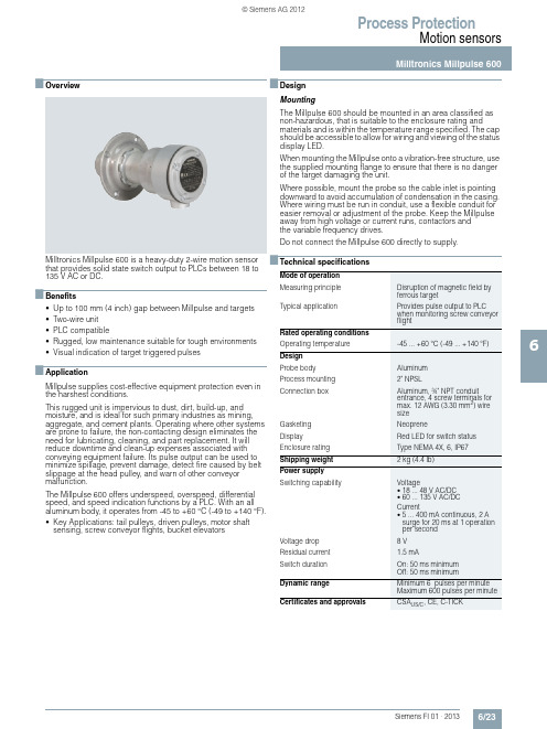
Process ProtectionMotion sensors6/236■OverviewMilltronics Millpulse 600 is a heavy-duty 2-wire motion sensor that provides solid state switch output to PLCs between 18 to 135 V AC or DC.■Benefits•Up to 100 mm (4inch) gap between Millpulse and targets •Two-wire unit•PLC compatible•Rugged, low maintenance suitable for tough environments •Visual indication of target triggered pulses■ApplicationMillpulse supplies cost-effective equipment protection even in the harshest conditions.This rugged unit is impervious to dust, dirt, build-up, andmoisture, and is ideal for such primary industries as mining, aggregate, and cement plants. Operating where other systems are prone to failure, the non-contacting design eliminates the need for lubricating, cleaning, and part replacement. It willreduce downtime and clean-up expenses associated withconveying equipment failure. Its pulse output can be used to minimize spillage, prevent damage, detect fire caused by belt slippage at the head pulley, and warn of other conveyormalfunction.The Millpulse 600 offers underspeed, overspeed, differential speed, and speed indication functions by a PLC. With an all aluminum body, it operates from -45 to +60 °C (-49 to +140 °F).•Key Applications: tail pulleys, driven pulleys, motor shaftsensing, screw conveyor flights, bucket elevators ■DesignMountingThe Millpulse 600 should be mounted in an area classified as non-hazardous, that is suitable to the enclosure rating andmaterials and is within the temperature range specified. The cap should be accessible to allow for wiring and viewing of the status display LED.When mounting the Millpulse onto a vibration-free structure, use the supplied mounting flange to ensure that there is no danger of the target damaging the unit.Where possible, mount the probe so the cable inlet is pointing downward to avoid accumulation of condensation in the casing.Where wiring must be run in conduit, use a flexible conduit for easier removal or adjustment of the probe. Keep the Millpulse away from high voltage or current runs, contactors andthe variable frequency drives.Do not connect the Millpulse 600 directly to supply.■Technical specificationsMode of operationMeasuring principle Disruption of magnetic field byferrous targetTypical application Provides pulse output to PLCwhen monitoring screw conveyorflightRated operating conditionsOperating temperature-45... +60 °C (-49... +140 °F) DesignProbe body AluminumProcess mounting2"NPSLConnection box Aluminum, ¾" NPT conduitentrance, 4 screw terminals formax. 12 AWG (3.30 mm2) wiresizeGasketing NeopreneDisplay Red LED for switch status Enclosure rating Type NEMA 4X, 6, IP67 Shipping weight 2 kg (4.4 lb)Power supplySwitching capability Voltage•18... 48 V AC/DC•60... 135 V AC/DCCurrent•5... 400 mA continuous, 2 Asurge for 20 ms at 1 operationper secondVoltage drop8 VResidual current 1.5 mASwitch duration On: 50 ms minimumOff: 50 ms minimumDynamic range Minimum 6 pulses per minuteMaximum 600 pulses per minute Certificates and approvals CSA US/C, CE, C-TICKProcess ProtectionMotion sensors6/246■Dimensional drawingsMillpulse 600 mounting, dimensions in mm (inch)Selection and Ordering dataOrder No.Milltronics Millpulse 600Heavy-duty 2-wire motion sensor that provides solid state switch output to PLCs between 18 ... 135V AC or DC.ModelMillpulse 600, aluminum enclosure, ¾" NPT, CE, C-TICK, CSA US/C approved (switches 18 ... 135V AC/DC)7MH7142-0AA10Selection and Ordering dataOrder codeFurther designsPlease add "-Z" to Order No. and specify Order code(s).Manufacturer’s test certificate: According to EN 10204-2.2C11Acrylic coated, stainless steel tag [13 x 45 mm (0.5x 1.75inch)]: Measuring-point number/identification (max. 16 characters), specify in plain text Y17Operating Instructions Order lpulse 600, English 7ML1998-5DG02Millpulse 600, German7ML1998-5DG31Millpulse 600, SpanishNote: The operating instructionsshould be ordered as a separate item on the order.This device is shipped with the Siemens Milltronics manual CD containing the complete operating inst-ructions library.7ML1998-5DG22Spare Parts Locknut 7MH7723-1CR Mounting flange7MH7723-1CS Motion cable gland adaptor kit7MH7723-1JNProcess ProtectionMotion sensors6/256■SchematicsMillpulse 600 mounting, dimensions in mm (inch)InterconnectionIf the manufacturer of your PLC does not state that it iscompatible with CENELEC 50040/36/37/38 electrical standards, then ensure that the switching current of the PLC input is above the residual current of the MillPulse. If your PLC does not meet the requirements, a resistor across the PLC inputs can be usedto increase the switching current.。
2英寸调节阀操作与维护手册说明书

TECH-SEAL INTERNATIONAL3131 West Little York Rd Houston, Texas 77091Phone: 713-691-0668Fax: 713-358-9330Adjustable Choke Operation and Maintenance ManualRevision: 0Date: 6/06/2013Approved By: J.ATABLE OF CONTENTS1.Introduction ……………………………………………………………………….page 32.Choke Specifications & Features………………………………………………….page 43.Choke Operation…………………………………………………………..………page 54.Exploded View…………………………………………………………………….page 65.Maintenance……………………………………………………………………….page 106.Contact information……………………………………………………………….page 18INTRODUCTION:The 2” Adjustable Chokes is field-proven design which have been manufactured by Tech-Seal International from the high quality material. Tech-Seal Chokes conform to current API requirements, both functionally and in term of calculated stresses. Adjustable Choke is used to control flow rate; it is an important part of a manifold controlling downstream pressure and flow rates during flow-back process.2” 1502 ADJUSTABLE CHOKE SPECIFICATION & FEATURES:Specifications:∙2” 1502 Female Inlet x 2” 1502 Male Outlet∙10,000 psig CWP/ 15,000 psig CWP∙¾” max Orifice and 1.00” max Orifice∙¾” FL/TC and 1.00” FL/TC Seats∙Solid carbide TipFeatures:∙Low Maintenance∙Easy to read position indicator∙Thumb Screw for locking steam∙Available as 2 types: Adjustable Choke and Positive Choke∙Forged steel bodies∙Available H2S service (NACE MR-01-75)∙Choice of orifice sizes∙Easy to convert orifice sizes in fieldCHOKE OPERATION:The 2” 1502 Adjustable Choke features the needle and seat design to allow controllingpressures and flow rate. The choke is operated by turning the hand wheel in CW or CCW in order to obtain a specified downstream pressure, or a desired flow rate.When the desired flow rate or specified pressured is achieved, the thumb screw will beused to locked the stem in fixed position.The choke comes with a position indicator. It is used to determine the bean size needed for the positive choke. Every number on the position indicator represents the equivalent orifice diameter in 1/64th of an inch.NOTE:THIS ADJUSTABLE CHOKE IS NOT DESIGNED TO PROVIDE A POSITIVE SEAL.THEREFORE, AN ISOLATION VALVE SHOULD BE USED IN CONJUNTION WITH THE CHOKE.EXPLODED VIEWS & PART LISTTHE THREE MAIN ASSEMBLIES OF THE CHOKE:Bonnet AssemblyChoke Tee BodyChoke Saver Assembly2” 1502 POSITIVE CHOKE∙EXPLODED VIEW:1 Wing Nut 4 Union Seal 2” 1502 7 Choke saver2 Retainer Ring 5 Body3 Blanking Cap 6 Split Ring∙REPLACEMENT PART & PART NUMBER2” 1502 ADJUSTABLE CHOKE EXPLODED VIEW:REPLACEMENT PART & PART NUMBER`MAINTENANCEWARNING:Tech-Seal Int’l cannot anticipate all of situations a user may encounter while installing, using or repairing products. Therefore, the user must know and follow all applicable industry specifications on the safe installation and use.Failure to follow these warning and instructions could result in serious injury or death!Disassembly:NOTE: Protecting all the sealing surfaces all the time during disassembly or installation process1.Secure the choke assembly on a stationary safe surface.2.Bleed off any internal pressure from the choke assembly3.Loosen the thumb screw and back up the stem away from the seat by turning thehandle CCW.4.Loosen the hammer nut and remove the bonnet assembly.5. Using a choke wrench to remove the seat from the choke tee body6.Remove thumb screw (10), hex nut (1), indicator (4), washer and hand wheel fromthe stem.7.Remove the wing nut(3) from the bonnet assembly8.Unscrew and remove the stem(15) from the bonnet assembly9.Unscrew two socket cap screws and remove the bonnet cap.ing an adjustable wrench to remove the drive bushing (6).11. Remove the snap ring (14) from the bonnet seal pocket.12.Remove stem guide (13), packing retainer (12) and packing set (11) from the sealpocket.13.Unscrew the wing nut to remove the choke saver (21) from the choke tee body(18).INSPECTION-Clean all components-Visual inspection for corrosion, erosion, or any sign of fatigue crack.-Check the shoulder radius of the male end connection for any sign of fatigue crack or corrosion damage.-Check minimum wall at the end connections (see the next page)-Inspect stem carbide tip, and replace as necessary.-Inspect stem sealing surface, and replace as necessary-Inspect stem external thread, and replace as necessary-Inspect seal pocket surface of the bonnet housing for any sign of wear and damage-Check the external thread and carbide surface of the seat for any sign of damage.NOTE:Tech-Seal Int’l highly recommended any dimensions found to be at or thinner the minimum wall thickness requirements, the part or component must be repaired or replaced. Do not use worn, eroded, corrode products.21TSI Flow Products, Inc. Corporate Office CLEBURNE, TX5656 Wheatley St.1717 Hines Rd. Houston, TX 77091 Cleburne, TX 76031 Phone: (713) 691‐0668 Toll Free: 888.593.9143 Fax: (713) 691‐2328 Phone: 817.773.2536Hours: Monday ‐Friday, 8AM ‐5PM CST. Fax: 817.506.7697 CORPUS CHRISTI, TX BRIDGEVILLE, PA 4517 Baldwin 580 Mayer St.Corpus Christi, TX 78408 Bridgeville, Pa. 15017 Toll Free: 877.886.0202 Phone 412‐257‐0100 Phone: 361.882.0202 Fax: 412‐980‐3722Fax: 361.882.0205 .rchurilla@tsi ‐ KILGORE, TXTOWANDA, PA 302 S. longview St. Rr#6 box 6019‐9 Kilgore, TX 75662 Reeves business park Toll Free: 877.984.2870 Towanda pa 18848 Phone: 903.984.2870 570 297 2300Fax: 903.983.3750bpond@tsi ‐。
QS600 6寸2路全频专业扬声器系统用户手册说明书

QS6006寸2路全频专业扬声器系统用户手册CN UM-QS600-20170808Ve r B感谢您购买 产品!请仔细阅读本手册,它将帮助你妥善设置并运行您的系统,使其发挥卓越的性能。
并保留这些说明以供日后参照。
警告:为了降低火灾与电击的风险,请不要将产品暴露在雨中或潮湿环境中。
警告:为了降低电击的风险,非专业人士请勿擅自拆卸该系统。
仅供专业人士操作。
等边三角形中的闪电标记,用以警示用户该部件为非绝缘体,系统内部存在着电压危险,电压。
可能足以引起触电。
可能足以引起触电如系统标有带惊叹号的等边三角形,则是为提示用户严格遵守本用户指南中的操作与维护规定。
注意:请勿对系统或附件作擅自的改装。
未经授权擅自改装将造成安全隐患。
警告:燃不得将明火源(如点的蜡烛)放在器材上面。
1. 请先阅读本说明。
2. 保留这些说明以供日后参照。
3. 注意所有警告信息。
4. 遵守各项操作指示。
5. 不要在雨水中或潮湿环境中使用本产品。
6. 不要将产品靠近热源安装,例如暖气管、加热器、火炉或其它能产生热量的装置(包括功放机 )。
7. 不要破坏极性或接地插头的安全性设置。
如果提供的插头不能插入插座,则应当请专业人员更换插座。
8. 保护好电源线和信号线,不要在上面踩踏或拧在一起(尤其是插头插座及穿出机体以外的部分 )。
9. 使用厂商规定及符合当地安全标准的附件。
10.雷电或长时间不使用时请断电以防止损坏产品。
12. 不要让物体或液体落入产品内——它们可能引起火灾或触电。
13. 请注意产品外罩上的相关安全标志。
. 仅与厂商指定或与电器一同售出的推车、架子、三脚架、支架或桌子一起使用。
推动小车电/器时,应谨防翻倒。
11注意事项产品的安装调试须由专业人士操作。
在使用非本厂规定的吊装件时,要保证结构的强度并符合当地的安全规范。
警告:1扬声器及扬声器系统的产品有限保修期为自正式购买日起的3年。
由于用户不合理的应用而导致音圈烧毁或纸盆损坏等故障,不包含于产品保修项目。
WattBox WB-600-FP 产品说明书
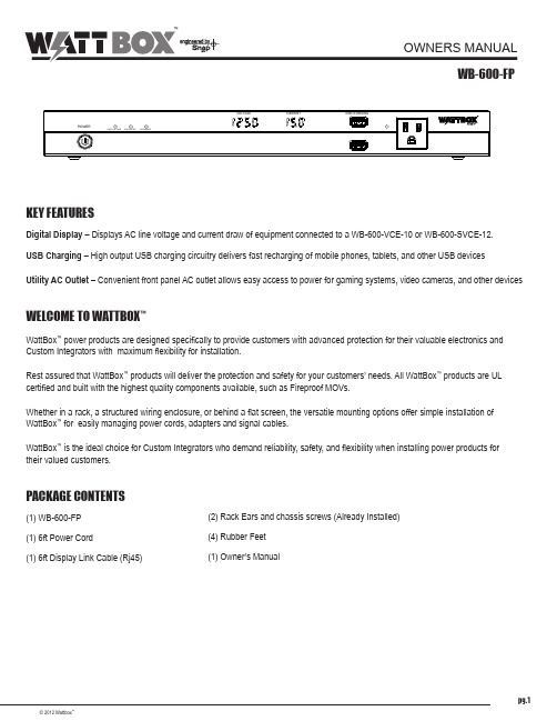
pg.1© 2012 Wattbox™OWNERS MANUALWB-600-FPKEY FEATURESDigital Display – Displays AC line voltage and current draw of equipment connected to a WB-600-VCE-10 or B Charging – High output USB charging circuitry delivers fast recharging of mobile phones, tablets, and other USB devices Utility AC Outlet – Convenient front panel AC outlet allows easy access to power for gaming systems, video cameras, and other devicesWELCOME TO WATTBOX ™WattBox ™ power products are designed specifically to provide customers with advanced protection for their valuable electronics and Custom Integrators with maximum flexibility for installation.Rest assured that WattBox ™ products will deliver the protection and safety for your customers’ needs. All WattBox ™ products are UL certified and built with the highest quality components available, such as Fireproof MOVs.Whether in a rack, a structured wiring enclosure, or behind a flat screen, the versatile mounting options offer simple installation of WattBox ™ for easily managing power cords, adapters and signal cables.WattBox ™ is the ideal choice for Custom Integrators who demand reliability, safety, and flexibility when installing power products for their valued customers.™PACKAGE CONTENTS(1) WB-600-FP (1) 6ft Power Cord(1) 6ft Display Link Cable (Rj45)(2) Rack Ears and chassis screws (Already Installed) (4) Rubber Feet (1) Owner’s ManualWATTBOX™ WB-600-FP Installation and Users ManualREAR PANEL1. Display link from WB-600-VCE-10 or WB-600-SVCE12 display connection.2. Detachable power cord outlet (Connects to WB-600-VCE-10 or WB-600-SVCE12 Display Link outlet). FRONT PANEL1. AC Power switch2. Status LEDS• Safe Voltage LED indicator light• Surge Protection LED indicator light• Ground LED indicator light3. Voltage Meter4. Current Meter5. USB Charging ports6. Utility AC Outletpg.2WATTBOX™ WB-600-FP Installation and Users Manual MOUNTING OPTIONSThe WB-600-FP can be placed in a cabinet at the top of the components or mounted to the front of a rack.Cabinet PlacementRack Mountingpg.3© 2012 Wattbox™WATTBOX™ WB-600-FP Installation and Users ManualIMPORTANT SAFETY INSTRUCTIONSPlease read and observe the following safety points at all times.WARNING – Power SourcesDo not plug this Component into a power outlet that differs from the source indicated for safe use on the Component. If you don’t know the type of electrical power that is supplied to your home, consult your local power company or a qualified electrician.WARNING – Grounding and PolarizationDo not force the Component plug into an outlet that is not designed to accept a three-wire grounded-type AC plug (a three-prong plug). This plug is designed to be inserted into a grounded-type outlet only. If this plug doesn’t fit directly inside the outlet, do not attempt to force a connection.. Never attempt to dismantle the plug in any way (or to alter the power cord). Do not attempt to defeat the grounding feature by using a 3-to-2 prong adapter. If you have questions about grounding, consult your local power company or a qualified electrician.This Wattbox™ component requires a properly grounded outlet for safety and to protect connected equipment. If you’re not sure if your home’s electrical wiring is properly grounded, have it checked by a qualified electrician.If any rooftop devices such as satellite dishes, antennas, or any other component with wire being used that connects to the Component, be sure the wire(s) is properly grounded. This protects against voltage surges and static charges.Do not place any antenna near overhead power lines or any other power circuit. Do not touch any power line or power circuit. Doing so may cause severe physical injury or possibly death.WARNING – Liquid: Avoiding Electrical ShocksDo not operate the Component if liquid of any kind is spilled onto or inside the unit. Do not operate the Component near rain or water that’s spilled or contained (e.g., bathtub, kitchen or sink).WARNING – Power Cord SafetyWhen routing the Component’s AC power cord, do not place it near heavy foot traffic areas (e.g., hallways, doorways, and floors). Do not create a trip hazard with the power cord.If the power cord’s protective jacket begins to rip or fray, exposing the internal wiring, shielding, etc., disconnect it from the AC power source and discontinue use of the Component immediately. See the Warranty Information section of this owner’s manual for important details.WARNING – No User Serviceable Parts InsideIf, for any reason, the Component is not operating properly, do not remove any part of the unit (cover, etc.) for repair. Unplug the unit and consult the Warranty Information section of this owner’s manual for important details.CAUTION – Exposure To HeatDo not expose the Component to direct sunlight or place it near wall heaters, space heaters, or any enclosed space prone to temperature increase.CAUTION – Proper CleaningIn general, the only cleaning necessary for the Component is a light dusting. Unplug the Component from the wall outlet before cleaning it. Do not use any type of liquid or aerosol cleaners.pg.4WATTBOX™ WB-600-FP Installation and Users Manualpg.5© 2012 Wattbox™TROUBLESHOOTINGSymptomPossible CauseRemedyThe Wattbox ™ is not receiving power.The Wattbox ™ is not turned On.• Turn the Wattbox ™ switch on.Make sure the Wattbox ™’s AC power plug is plugged into a properly grounded 120 volts (nominal) wall outlet.•In some households, a wall switch may need to be turned on to make the wall outlet active. Try turning on the light switches located near the wall outlet.Too many devices are connected, causing an overload, tripping the Thermal Circuit Breaker.•Press the Wattbox ™ resettable circuit breaker button in to reset. Please allow 10 minutes before attempting to reset. If reset too soon, thebreaker will prematurely sense power overload and not allow the Wattbox ™ to operate.•If the circuit breaker continues to trip, try moving one or more components to another Wattbox ™. Too much current may be drawing through one Wattbox ™.Component is not receiving power.The component is plugged into a switched outlet and the Wattbox ™has not been turned On.•Turn the Wattbox ™ On.•Or, plug the component into an unswitched outlet.The Wattbox ™ is plugged into a switched outlet, but power on the component is not On. In some instances, a component plugged into a switched outlet won’t receive power when the Wattbox ™ is turned On unless the component power is also switched On.• Turn the component power On.Speakers emit a humming or buzzing noise.The Wattbox ™ is sharing AC power with equipment that is not properly grounded.• Connect your Wattbox ™ to a dedicated outlet.•Try unplugging different components from the Wattbox ™ one at a time to see if the noise stops.•If a component is discovered to be improperly grounded, attach a copper wire from the component’s chassis to the Wattbox ™’s grounding post.Contacting Technical Support - Phone: (866) 838-5052 - Email:**********************SPECIFICATIONSAC Power Line Voltage 120V, 60HzFront Panel USB Circuit Faceplate Option WB‐600‐FPJacks Standard A (2)Power 1.5 Amp distributedAC Outlet NEMA 5‐15Display Link Inputs Display Communication RJ45Display Power IEC C‐14Power Cord Length 6 FeetDisplays Voltage 3 Digit LED DisplayCurrent 2 Digit LED DisplayUL Certifications UL 60950‐1, UL 498WARRANTYLifetime Limited WarrantyThis SnapAV® product has a Lifetime Limited Warranty. This warranty includes parts and labor repairs on all components found to be defective in material or workmanship under normal conditions of use. This warranty shall not apply to products which have been abused, modified or disassembled. Products to be repaired under this warranty must be returned to SnapAV or a designated service center with prior notification and an assigned return authorization number (RA).CONTACTING TECHNICAL SUPPORTPhone: (866) 838-5052 - Email:**********************120604-1130© 2012 Wattbox™。
TC600中文说明书(II)

TCH-600氧氮氢联测仪中文说明书力可公司1介绍1 介绍☐插图说明……………………………………………………..………………..…1-12 ☐保证书……..………………..………………..………………..…………………1-15 注意事项.………………….………………….………………….………………1-16 警告事项.………………….………………….………………….………………1-16 ☐警告符号.………………….………………….………………….………………1-17 ☐和其它设备的接口.………………….………………….………………….……1-18 ☐主设备及附件列表……………………………………………………..……… 1-20 ☐选用件…..………………………..……………………………..……....……… 1-21 ☐部件和附件列表…………………………………..……………………..………1-22 ☐技术规格……………………………………………………………..…………...1-26 ☐即时手册…………………………………………………………..…………...….1-282 安装☐插图说明……………………………………………………..………………..… 2-2 ☐抬举和移动仪器……………………………………………..………………..… 2-3 ☐仪器安装…………………………………………………………………..………2-4 ☐设备要求…………………………………………………………………..………2-7 ☐电源安装…………………………………………………………………..………2-9 国内电源安装……………………………………………………………..………2-9 电源选择…………………………………………………………………..…… 2-10 国际电源安装……………………………………………………………..…… 2-12 交流电缆的技术规格……………………………………………………..…… 2-12 ☐电极炉冷却系统…………………………………………………………..…… 2-13 ☐入口气体净化试剂的安装………………………………………………..…… 2-15☐分析气体净化试剂的安装………………………………………………………………2-16 ☐氧气和水分吸收试剂管的安装…………………………………………………………2-18 ☐吸尘器的安装……………………………………………………………………………2-20 ☐计算机的安装……………………………………………………………………………2-21 LECO提供的计算………………………………………………………………………2-21 用户提供的计算………………………………………………………………………… 2-23 最低的计算机配置……………………………………………………………………… 2-23 3选用件安装☐插图说明…………………………………………………………………………………3-2 ☐天平的安装………………………………………………………………………………3-3 天平的设置………………………………………………………………………………3-3 天平初始化………………………………………………………………………………3-4 天平测试…………………………………………………………………………………3-5 ☐打印机……………………………………………………………………………………3-7 4系统设置☐插图说明…………………………………………………………………………………… 4-3 ☐控制及指示………………………………………………………………………………….4-4 ☐自动传送分析结果………………………………………………………………………….4-6 ☐维护计数值设定…………………………………………………………………………….4-8 维护计数值定义…………………………………………………………………………….4-9 ☐生成分析报告……………………………………………………………………………….4-10 ☐屏幕排版…………………………………………………………………………………….4-12 工具栏……………………………………………………………………………………… 4-12 状态栏……………………………………………………………………………………… 4-12 桌面栏……………………………………………………………………………………… 4-12 ☐分析表格设定……………………………………………………………………………… 4-13 表格内容定义……………………………………………………………………………… 4-14 ☐分析方法设定……………………………………………………………………………… 4-15 分析方法定义……………………………………………………………………………… 4-17 分析参数设定………………………………………………………………………… 4-17 元素参数设定………………………………………………………………………… 4-17 气标参数设定………………………………………………………………………… 4-18 炉子参数设定………………………………………………………………………… 4-19步进分析参数设定……………………………………………………………………… 4-21 ☐样品模板…………………………………………………………………………………… 4-23创建样品模板……………………………………………………………………………… 4-23 登录使用样品模板………………………………………………………………………… 4-24 ☐标样………………………………………………………………………………………… 4-25 标样定义…………………………………………………………………………………… 4-26 ☐系统设定…………………………………………………………………………………….4-27 系统设置的定义…………………………………………………………………………… 4-29 系统设置……………………………………………………………………………….4-29 天平设置……………………………………………………………………………….4-31 ☐传送格式…………………………………………………………………………………… 4-32 定义传送内容……………………………………………………………………………… 4-33 定义传送符号……………………………………………………………………………… 4-34 串行口……………………………………………………………………………………… 4-35 串行口定义…………………………………………………………………………… 4-36 预览传送数据……………………………………………………………………………… 4-37 ☐用户设定…………………………………………………………………………………… 4-38 添加用户…………………………………………………………………………………… 4-38 添加密码…………………………………………………………………………………… 4-39 指定用户功能……………………………………………………………………………… 4-40 ☐语言选择…………………………………………………………………………………… 4-415操作☐插图说明…………………………………………………………………………………… 5-5 ☐操作指南…………………………………………………………………………………… 5-6 分析前……………………………………………………………………………………… 5-7 分析后……………………………………………………………………………………… 5-8 使用后……………………………………………………………………………………… 5-8 ☐坩埚………………………………………………………………………………………5-9 标准坩埚…………………………………………………………………………………5-10 加热坩埚…………………………………………………………………………………5-10 高温坩埚…………………………………………………………………………………5-10 ☐电极清扫刷坩埚…………………………………………………………………………5-11 ☐样品制备…………………………………………………………………………………5-12 ☐样品种类…………………………………………………………………………………5-12屑状样品……………………………………………………………………………5-12粉末样品……………………………………………………………………………5-12胶囊样品……………………………………………………………………………5-12样品尺寸……………………………………………………………………………5-12 流动试剂…………………………………………………………………………………5-13 清洗及安装镍兰……………………………………………………………………5-13超高温纯净镍兰……………………………………………………………………5-13 Windows软件菜单……………………………….……………………………………… 5-14 文件菜单…………………………………….……………………………………………5-14 打印…………………………………….……………………………………………5-14 打印预览……………………………………………………………………………5-14打印设置……………………………………………………………………………5-14输入…………………………………….……………………………………………5-15 输出…………………………………….……………………………………………5-15 退出………….……………………………………………………………………….. 5-15 编辑菜单…………………………………….……………………………………………5-16 插入…………………………………….……………………………………………5-16 填充…………………………………………………………………………………5-16 剪切…………………………………….……………………………………………5-16 复制…………………………………….……………………………………………5-16 粘贴………….………………………………………………………………………5-16 视图菜单…………………………………….……………………………………………5-17 工具栏………………………………….……………………………………………5-17 状态栏………………………………………………………………………………5-17 第一行………………………………….……………………………………………5-17 分析栏………………………………….……………………………………………5-17 上一行………….……………………………………………………………………5-17 仪表盘…………….……………………………………………………………………5-18 峰值寻找……………………………………………………………………………… 5-18 氧化物分离(OxSep)………………………………………………………………..5-18 样品菜单…………………………………….……………………………………………5-19 登录…………………………………….……………………………………………5-19 天平…………………………………………………………………………………5-19 分析…………………………………….……………………………………………5-19 终止…………………………………….……………………………………………5-19传送…………………………………………………………………………………5-20删除…………………………………….……………………………………………5-20 设置菜单…………………………………….……………………………………………5-21 校正…………………………………….……………………………………………5-21空白…………………………………………………………………………………5-21漂移校正……………………………….……………………………………………5-21标样…………………………………….……………………………………………5-22方法………….………………………………………………………………………5-22计数器………………………………….……………………………………………5-22样品模板……………………………………………………………………………5-22 系统…………………………………….……………………………………………5-22用户…………………………………….……………………………………………5-22传送格式…….………………………………………………………………………5-23语言…………………………………….……………………………………………5-23自动调宽……………………………….……………………………………………5-23显示…………………………………………………………………………………5-23 诊断菜单…………………………………….……………………………………………5-24 环境监视……………………………….……………………………………………5-24环境监视表…………………………………………………………………………5-24 开关…………………………………….……………………………………………5-24漏气检查……………………………….……………………………………………5-24电磁阀……….………………………………………………………………………5-24自动装置……………………………….……………………………………………5-25电极炉………………………………………………………………………………5-25校正…………………………………….……………………………………………5-25网络…………………………………….……………………………………………5-25 维护菜单…………………………………….……………………………………………5-26 登录…………………………………….……………………………………………5-26显示日志文件………………………………………………………………………5-26 ☐登录试样……………………………………………………………………………………5-27 试样登录定义………………………………………………………………………………5-28 天平登录……………………………………………………………………………………5-28 ☐分析试样……………………………………………………………………………………5-29 ☐删除试样……………………………………………………………………………………5-30 ☐打印样品结果………………………………………………………………………………5-31☐传送结果……………………………………………………………………………………5-33 ☐重新计算结果………………………………………………………………………………5-34 ☐校正…………………………………………………………………………………………5-35 ☐空白校正……………………………………………………………………………………5-36 ☐标样校正……………………………………………………………………………………5-37 标样校正定义…………………………………………………………………………5-39☐漂移校正……………………………………………………………………………………5-40 ☐结果管理……………………………………………………………………………………5-41 在分析表中插入数据…………………………………………………………………5-41插入分析………………………………………………………………………………5-42在选择的表格中设置相同的值………………………………………………………5-42在分析表中选择第一行………………………………………………………………5-43在分析表中选择第分析行……………………………………………………………5-43在分析表中选择上一行………………………………………………………………5-43输入样品数据…………………………………………………………………………5-43输出样品数据…………………………………………………………………………5-44输出定义………………………………………………………………………………5-46 ☐使用剪贴板……………………………………………………………..…………………..5-47 剪切数据到剪贴板…………………………………………………..………………..5-47复制数据到剪贴板…………………………………………………..………………..5-47粘贴数据到剪贴板…………………………………………………..………………..5-47 ☐分析图形设置………………………………………………………………………………5-48 显示菜单………………………………………………………………………………5-48 选择过程…………………………………………………………………………5-48 ☐峰值寻找……………………………………………………………………………………5-50 图形菜单…………………………………………………………………………….. 5-51 图形菜单定义……………………………………………………………………5-51 打印图形…………………………………………………………………………….. 5-51峰值寻找方法建立……………………………………………………………………5-52 峰值寻找方法定义………………………………………………………………5-53☐氧化物分离(OxSep)………………...…………………………………..………5-54 氧化物分离图形………………...………………...…………………..………5-54 氧化物分离图形功能…………...…………..…………………..………5-55 打印图形………………...…………….………..………………..…………5-56氧化物分离方法建立………………...……………..………………..………5-57氧化物分离方法定义…………...……………..………………..………5-58典型方法的参数………………….……………………………………5-59系统设置………………...…………………………………………………5-60数据缓冲区数据移位定义………………….…………………..………5-616维护☐插图说明…………………………………………………………………………………… 6-2 ☐维护周期表………………………………………………………………………………….6-3 ☐空气过滤器清扫…………………………………………………………………………….6-5 ☐入口催化剂充填……………………………………………………………………………6-7 ☐分析气催化剂充填………………………………………………………………………… 6-8 ☐加样器过滤器……………………………………………………………………………….6-12 ☐登录周期维护……………………………………………………………………………….6-14 ☐下电极座和O型圈的更换…………………………………………………………………6-15 ☐炉子过滤器充填…………………………………………………………………………… 6-17 ☐汽缸密封O型圈和滑块……………………………………………………………………6-19 ☐落样块O型圈和落样块……………………………………………………………………6-21 ☐次级过滤器………………………………………………………………………………… 6-23 ☐检查日志文件……………………………………………………………………………… 6-25 ☐更新维护计数器…………………………………………………………………………… 6-267工作原理☐工作原理……………………………………………………………………………………..7-3 ☐大气压力……………………………………………………………………………………..7-5 ☐校正曲线选择………………………………………………………………………………..7-7 线性校正……………………………………………………………………………………..7-8 校正技巧………………………………………………………………………………..7-8 两次曲线校正………………………………………………………………………………..7-9 校正技巧………………………………………………………………………………..7-9 三次曲线校正………………………………………………………………………………..7-10 校正技巧………………………………………………………………………………..7-10 ☐比较水平……………………………………………………………………………………..7-11 ☐分步气体分析和程序升温………………………………………………………………7-13 概述…………………………………………………………………………………………..7-13 程序升温……………………………………………………………………………………..7-14 升温方法………………………………………………………………………………..7-14温度保持-氧………………………………………………………………………….7-15温度保持-步进………………………………………………………………………..7-15 ☐红外辐射、吸收和检测……………………………………………………………………..7-16 ☐热导检测………………...………………………………..………………..……7-17 气体的热导率………………...………………………………………..……7-188诊断☐环境监测……………………………………………………………………………………..8-3 环境监测表…………………………………………………………………………………..8-4 环境监测虚拟表……………………………………………………………………………..8-5 环境监测定义…………………………………………………………………………..8-6 ☐校正………………………………………………………………………………………… 8-8 催化炉……………………………………………………………………………………… 8-8 设置大气压力……………………………………………………………………………… 8-11 设置载气流量……………………………………………………………………………… 8-12 热导池电压校准………………...…………...………………………..………… 8-13 热导池电桥电压检查………………......……………………………..……8-13设置电桥………………...…………………………….………………..……8-14 备份校正…………………………………………………………………………………… 8-15 备份校正值…………………………………………………………………………… 8-16恢复校正值…………………………………………………………………………… 8-17 网络………………………………………………………………………………………… 8-18 网络定义……………………………………………………………………………… 8-20 ☐炉子诊断……………………………………………………………………………………8-21 ☐漏气检查…………………………………………………………………………………… 8-23 ☐电磁阀……………………………………………………………………………………… 8-25 ☐开关………………………………………………………………………………………… 8-26 开关状态…………………………………………………………………………………… 8-27 泵头温度……………………………………………………………………………… 8-27泵头压力……………………………………………………………………………… 8-27冷却水温度…………………………………………………………………………… 8-27电极温度……………………………………………………………………………… 8-27变压器温度…………………………………………………………………………… 8-27 ☐自动装置…………………………………………………………………………………… 8-29 自动清扫…………………………………………………………………………………… 8-29 自动加样…………………………………………………………………………………… 8-30☐电子调整…………………………………………………………………………………… 9-310维修☐插图说明…………………………………………………………………………………… 10-2 ☐分析气路图………………………………………………………………………………… 10-3 参考气流路径……………………………………………………………………………… 10-3 测量气流路径……………………………………………………………………………… 10-4 ☐冷却水槽的排水…………………………………………………………………………… 10-5 ☐漏气故障处理……………………………………………………………………………… 10-7 旁路系统…………………………………………………………………………………… 10-7 ☐报警信息…………………………………………………………………………………… 10-8 ☐可弯曲可更换的气路管…………………………………………………………………… 10-12 气路管的部件号…………………………………………………………………………… 10-12 ☐线性化……………………………………………………………………………………… 10-13 ☐电磁阀说明表图…………………………………………………………………………… 10-1511插图目录12目录13简图和附件列表图2-1………………………TCH-600后面板图……………………………………………… 2-8图2-2………………………电压选择图示………………………………………………………2-11图2-3………………………添加冷却水图………………………………………………………2-14图2-4………………………试剂管充填图………………………………………………………2-17图2-5………………………除氧气和水分试剂管帽的拆卸图…………………………………2-19图2-6………………………除氧气和水分试剂管的拆卸图……………………………………2-20图2-7………………………吸尘器的安装图……………………………………………………2-21图3-1………………………天平控制板…………………………………………………………3-6图3-2………………………天平装置……………………………………………………………3-6图4-1………………………控制器和显示器……………………………………………………4-5图5-1………………………坩埚类型……………………………………………………………5-9图6-1………………………空气过滤器的位置图………………………………………………6-6图6-2………………………催化炉试剂管的位置图……………………………………………6-10图6-3………………………催化炉试剂管的充填图……………………………………………6-11图6-4………………………加样头过滤器的更换图……………………………………………6-13图6-5………………………下电极座和O型圈的更换图………………………………………6-16图6-6………………………微粒过滤器的更换图………………………………………………6-18图6-7………………………活塞密封O型圈和滑块图…………………………………………6-20图6-8………………………落样块图……………………………………………………………6-22图6-9………………………次过滤器图……………………………………………………… 6-24图10-1………………………冷却水槽排水图………………………………………………… 10-6图10-2………………………TCH-600气路图……………………………………………… 10-17图10-3………………………漏气检查顺序图………………………………………………… 10-18图11-1………………………红外池和热导池恒温箱………………………………………… 11-4 图11-2………………………红外池装配图…………………………………………………… 11-5图11-3………………………红外检测器装配图……………………………………………… 11-6图11-4………………………热导池装配图…………………………………………………… 11-7图11-5………………………动态流量补偿器装配图………………………………………… 11-8图11-6………………………热交换器装配图………………………………………………… 11-9图11-7………………………冷却水闭环系统图……………………………………………… 11-10图11-8………………………液-液热交换装配图…………………………………………… 11-11图11-9………………………冷却水阀装配图………………………………………………… 11-12图11-10……………………催化炉加热装配图……………………………………………… 11-13图11-11……………………分析气催化炉加热装配图……………………………………… 11-14图11-12……………………入口气体净化装配图…………………………………………… 11-15图11-13……………………恒温箱加热装配图……………………………………………… 11-16图11-14……………………上电极装配图…………………………………………………… 11-17图11-15……………………下电极装配图…………………………………………………… 11-18图11-16……………………计量阀装配图…………………………………………………… 11-19图11-17……………………变压器装配图…………………………………………………… 11-20图11-18……………………微颗粒过滤器装配图…………………………………………… 11-21图11-19……………………底板和支架装配图……………………………………………… 11-22图11-20……………………交流电源分配板………………………………………………… 11-23图11-21……………………加样头过滤器…………………………………………………… 11-24图11-22……………………电源装配图……………………………………………………… 11-25图11-23……………………质量流量控制器装配图………………………………………… 11-26图11-24……………………冷却水泵装配图………………………………………………… 11-27图11-25……………………动力气模块装配图……………………………………………… 11-28图11-26……………………除氧气和水分试剂管模块装配图……………………………… 11-29图11-27……………………加样头装配图…………………………………………………… 11-30图11-28……………………下电极座装配图………………………………………………… 11-31图11-29……………………短电极刷装配图………………………………………………… 11-32图11-30……………………长电极刷装配图………………………………………………… 11-33图11-31……………………氦气连接装配图………………………………………………… 11-34图11-32……………………动力气连接装配图……………………………………………… 11-35图11-33……………………排水管装配图…………………………………………………… 11-36图11-34……………………电极炉装配图…………………………………………………… 11-37图11-35……………………视图A…………………………………………………………… 11-38图11-36……………………视图B…………………………………………………………… 11-39图11-37……………………视图C…………………………………………………………… 11-40图11-38……………………金属气路管更换指导…………………………………………… 11-41由美国密歇根州约瑟夫街LECO公司生产的仪器保证自安装之日起六个月在材料和工艺方面的保质期。
爱特顿PDG32M0600D2WJ电源防御型号电流保护电路断路器说明书

Eaton PDG32M0600D2WJEaton Power Defense molded case circuit breaker, Globally Rated, Frame 3, Two Pole, 600A, 65kA/480V, PXR20D LSI w/ Modbus RTU, ZSI and Relays, Standard Line and Load (PDG3X2TA632)General specificationsEaton Power Defense molded case circuit breakerPDG32M0600D2WJ 786679572177109.1 mm 257.1 mm 138.9 mm 5.2163 kg Eaton Selling Policy 25-000, one (1) year from the date of installation of theProduct or eighteen (18) months from thedate of shipment of the Product,whichever occurs first.RoHS Compliant IEC 60947-2CSAUL 489CCC MarkedProduct NameCatalog Number UPCProduct Length/Depth Product Height Product Width Product Weight WarrantyCompliancesCertificationsZSI / Modbus / Relays65 kAIC at 480 Vac3600600 ATwo-pole600 VPD3 Global22 kAIC Icu @250 Vdc 100 kAIC @240V (UL)ElectronicClass AComplete breakerStandard Line and Load600 VacPXR 20D LSIModbus RTU Eaton Power Defense MCCB PDG32M0600D2WJ 3D drawingPower Xpert Protection Manager x64Consulting application guide - molded case circuit breakersStrandAble terminals product aidPower Defense technical selling bookletPower Defense brochurePower Defense molded case circuit breaker selection posterPower Xpert Release trip units for Power Defense molded case circuit breakersMolded case circuit breakers catalogPDG3 CSA certification 100-400aPDG3 CSA certification 250-600aPDG3 UL authorization 100-400aPDG3B 450A-600A CB reportPDG3 45-400A CB reportPDG3 UL authorization 250-600a TMTUEU Declaration of Conformity - Power Defense molded case circuit breakersPower Defense Frame 3 interphase barrier - IL012229EN H03 Power Defense Frame 1-2-3-4 IP door barrier assembly instructions - IL012278ENPower Defense Frame 3 handle mech direct rotary handle instructions - IL012111ENPower Defense Frame 3 locking devices and handle block instructions - IL012150ENPower Defense Frame 3 reverse feed connector kit Cat NumPDG3X3(2)(4)TA400HRF instructions - IL012252ENPower Defense Frame 4 locking devices and handle block instructions - IL012151ENPower Defense Frame 3 plug-in adapter installation instructions -IL012311ENPower Defense Frame 3 multi wire connector kit -Special featuresInterrupt ratingFrameRated operation voltage (Ue) at AC - max Amperage RatingNumber of polesVoltage rating - maxCircuit breaker typeInterrupt rating rangeSwitch off techniqueClassCircuit breaker frame typeTerminalsVoltage ratingTrip TypeCommunication 3D CAD drawing package Application notes BrochuresCatalogsCertification reports Installation instructionsPDG3X3(2)(4)TA4006W and PDG3X3(2)(4)TA4003W instructions-IL012247EN H01Power Defense Frame 4 shunt trip UVR instructions - IL012129EN Power Defense Frame 3 Direct Rotary Handle Assy With Interlock Version Instructions (IL012139EN).pdfPower Defense Frame 3 Aux, Alarm, ST and UVR Animated Instructions.rh Power Defense Frame 3 Breaker Instructions (IL012107EN).pdfPower Defense Frame 3 terminal spreader assembly instructions -IL012301ENPower Defense Frame 2/3/4/5/6 voltage neutral sensor module wiring instructions – IL012316ENPower Defense Frame 3 finger protection assembly installation instructions - IL012279ENPower Defense Frame 3 box terminal installation instructions -IL012299ENPower Defense Frame 3 reverse feed connector kit Cat NumPDG3X3(2)(4)TA630RF instructions - IL012253ENPower Defense Frame 4 reverse feed connector kit instructions for PDG4X3(2)(4)TA800RF instructions - IL012254ENPower Defense Frame 3 trip unit replacement instructions - IL012157EN Power Defense Frame 3 terminal kit Cat Num PDG3X3(2)(4)TA400RF instructions - IL012251ENPower Defense Frame 3 rear connection installation instructions -IL012300ENPower Defense Frame 3 shunt trip UVR instructions - IL012140EN Power Defense Frame 3 extendable shaft rotary handle mech -IL012112ENPower Defense Frame 3 adapter kit installation instructions LZM3 to PD3 - IL012227ENPower Defense Frame 3 multi-tap terminal kit Cat NumPDG3X3(2)(4)TA6006W Instructions - IL012248ENInstallation videosPower Defense Frame 3 trip unit replacement animated instructions.rh Power Defense Frame 3 Shunt Trip_UVR Animated Instructions.pdf.rh Power Defense Frame 3 Handle Mech Variable Depth Rotary Handle Animated Instructions.rhPower Defense Frame 3 Handle Mech Direct Rotary Handle Animated Instructions.rhPower Defense Frame 3 Locking Devices and Handle Block Animated Instructions.pdf.rhMultimediaPower Defense Frame 3 Aux, Alarm, Shunt Trip, and UVR How-To VideoEaton Corporation plc Eaton House30 Pembroke Road Dublin 4, Ireland © 2023 Eaton. All Rights Reserved. Eaton is a registered trademark.All other trademarks areproperty of their respectiveowners./socialmediaPower Defense Frame 5 Trip Unit How-To Video Power Defense Frame 6 Trip Unit How-To VideoPower Defense Frame 3 Variable Depth Rotary Handle Mechanism Installation How-To VideoPower Defense Frame 2 Variable Depth Rotary Handle Mechanism Installation How-To VideoPower Defense molded case circuit breakers Power Defense BreakersEaton Power Defense for superior arc flash safety Eaton Specification Sheet - PDG32M0600D2WJ Power Defense time current curve Frame 3 - PD3Single and double break MCCB performance revisited Intelligent power starts with accurate, actionable data Making a better machineImplementation of arc flash mitigating solutions at industrial manufacturing facilitiesMolded case and low-voltage power circuit breaker health Intelligent circuit protection yields space savings Molded case and low-voltage breaker health Safer by design: arc energy reduction techniquesSpecifications and datasheetsTime/current curvesWhite papers。
唯创电子 WTN6 系列语音芯片说明书 - 中文

广州唯创电子有限公司MP3录音模块WTN6系列语音芯片说明书V1.19Note:WAYTRONIC ELECTRONIC CO.,LTD.reserves the right to change this document without prior rmation provided by WAYTRONIC is believed to be accurate and reliable.However,WAYTRONIC makes no warranty for any errors which may appear in this document.Contact WAYTRONIC to obtain the latest version of device specifications before placing your orders.No responsibility is assumed by WAYTRONIC for any infringement of patent or other rights of third parties which may result from its use.In addition,WAYTRONIC products are not authorized for use as critical components in life support devices/systems or aviation devices/systems,where a malfunction or failure of the product may reasonably be expected to result in significant injury to the user,目录1.概述: (2)2.功能简述: (2)3.管脚描述: (2)3.1管脚分布图 (3)4.极限参数: (3)5.直流特性: (3)6.一线串口通讯: (4)6.1管脚分配: (4)6.2一线语音地址对应关系: (5)6.3一线语音及命令码对应表: (5)6.4一线串口时序图: (6)7.两线串口通讯: (7)7.1管脚分配: (7)7.2语音地址对应关系: (7)7.3语音及命令码对应表: (7)7.4两线串口时序图: (8)8.数脉冲控制方式: (9)8.1管脚分配: (9)8.2语音地址对应关系: (9)8.3数脉冲控制时序: (10)9、按键控制模式 (10)10.程序范例 (12)10.1一线串口控制程序 (12)10.2二线串口控制程序 (13)10.3数脉冲控制程序 (14)11.应用电路 (15)11.1一线串口应用电路 (15)11.2两线串口应用电路 (16)11.3数脉冲应用电路 (18)11.4按键应用电路 (19)12.封装管脚图 (21)1.概述:WTN6系列为多功能,低功耗,高性能的CMOS语音芯片。
WT1800中文说明书2版

谐波测量功能 ( 选件 ) .................................................................................................................... 1-3
Delta 运算功能 ( 选件 ) .................................................................................................................. 1-5
Delta 运算 (Δ Measure; 选件 ) ..................................................................................................... 2-6
选择要指定测量量程的单元 (ELEMENT) ...................................................................................... 2-8
自动电压量程 (AUTO (V)) ........................................................................................................... 2-10
电流量程 (RANGE UP/DOWN (A)) ..............................................................................................2-11
距平麦金2操作说明书

IMAXIMIssue 2 12.01.99MAXIM AmplifierOperating InstructionsBaldwin Boxall Communications Ltd.Wealden Industrial Estate, Farningham RoadCrowborough, East Sussex, TN6 2JRTelephone: 01892 664422 Fax: 01892 663146Email:*********************.ukM AXIM D ESCRIPTION AND S PECIFICATIONS1.120W RMS Power Output.2.Mains or 24V DC Battery powered with silent changeover.3.Four balanced microphone inputs via 180º and 240º DIN sockets.4.Each input has the option of cascade priority via internal switch selection.5.As supplied each input has the chime and volume restoration/busy enabled, this is selectable viaan internal diode matrix (see fig 1).6.Optional three note chime (plug in module OPT33) with pre-set volume control.7.Master volume, treble and bass controls.8.Auxiliary stereo music input (internally mixed) to accept tuners, CD players or tape decks.9.Music mute facility which allows music to be ‘ducked’ to a pre-set level when paging operated.10.Remote music mute input from time clocks etc.11.24V DC output.12.“Volume Restoration” relay to provide simple zoned output (e.g. paging only)13.Open collector “Busy” output to drive indicators etc.14.Auxiliary output to feed slave amplifiers, tape decks etc.SAFETYVentilationAlways ensure adequate ventilation to the amplifier : do not obstruct ventilation holes in cover or base. AC Power Input - Danger High VoltageOnly connect to an AC 50-60 Hz 230V supply using the lead assembly supplied or an equivalent type with a suitable IEC connector.Always ensure that the amplifier is earthed.Always unplug the power before removing the top cover.100V Loudspeaker Output - Danger High VoltageEnsure that the loudspeaker connections are suitably protected and cannot be touched. Always replace output plug insulated covers.Always ensure that the total speaker load does not exceed 120 Watts. If unsure use an impedance meter to measure the unknown load. Using a multimeter selected to the resistance range ensure that the speaker line is not connected to earth.MoistureDo not allow water to come in contact with the amplifier and its external connections.Cable TypesAlways ensure that the correct cable type is used for the signal level.A twin screened cable should be used for balanced inputs operating at mic level. Zone selection and access control cables do not generally require screening and should not share the same screen as the balanced input.Loudspeaker output cables should be rated in excess of 100V and the cross sectional area to suit the load without excessive power loss. Always ensure that output cables are kept as far away from input cables as possible reducing the risk of instability.FusesAlways replace using the correct rating and type to ensure safe operation.M AXIM 120W TECHNICAL SPECIFICATIONRated output power100V Line 230V AC Supply120W 83 OhmsTHD 1kHz rated outputAux input 230V AC SupplyLess than 0.5%, typically 0.2%Typical output power 1% THDAux input 230V AC supply150W 66 OhmsOutput regulation(1kHz 100V Line)Better than 1.3dBOutput voltages obtainable(Pin selection)50 & 100VSupply Voltage22-35V DC220-240V 50-60Hz AC Power ConsumptionQuiescentRated Output Power @ 1kHz 120mA9A18VA300VAFuse Protection1 x AC Supply 20 x 5mm1 x DC (amplifier) auto blade 1 x Battery Supply auto blade 3.15A (T) 15A (F) 15A (F)Aux input stereo summed monoSensitivityFrequency response – 3dB@ Signal to noise ratio 120mV @ 20k Ohms 40Hz – 20kHz Better than 80dBMic InputSensitivityFrequency response –3dB@Signal to noise ratio terminated 200 Ohms 600!V Balanced @ 660 Ohms60Hz – 12kHzBetter than 60dBTone ControlsBass Treble +/- 12dB @ 100Hz +/- 12dB @ 12kHzAuxiliary OutputOutput LevelRecommended load impedance400mV @ 1kOhm Greater than 10kOhmSystem busy output Open collector 0.5A @ 40V total max. Busy / Restoration relay output 2 pole changeover 5A @ 100V max. DC Aux output**************************** TerminationsAC supply inputDC Battery inputAux inputMic inputSub socketBusy / Restoration relay output Loudspeaker line output3-pin DIN IEC 6A3-pin Screw terminated connector 180" 5 pin DIN stereo summed mono 180" 5 pin & 240" 6 pin DIN180" 5 pin & 240" 5 pin DIN8-pin, Screw terminated connector 3-pin Screw terminated connectorDimensions (mm) (D x W x H)340 x 430 x 90 Weight12kgC ASCADE P RIORITY AND D IODE M ATRIXC ASCADE P RIORITYCascade Priority can be selected on the four microphone inputs using the “Priority Select” DIL switch on the PCB.As supplied from the factory the 4 microphone inputs mix and do not override the music input.To enable a microphone input to override the music input and lower priority microphone inputs the relevant switch should be set to “ON”.D IODE M ATRIXAs supplied from the factory each microphone input (when accessed) enables the chime, Busy output, and Volume Restoration relay.To prevent an input having one of these facilities then the relevant diode should be cut out of circuit.。
慧宇伟业 WT600J-2A 蠕动泵使用说明书

WT600J-2A蠕动泵使用说明书慧宇伟业(流体设备有限公司北京)HUIYUWEIYE (BEIJING) FLUID EQ UIPM ENT CO., LTD.产品简介WT600J-2A使用说明书安全信息操作面板基本操作启停控制方向控制调速功能全速功能外控输入信号调速功能外控航空插头引脚定义适用泵头和软管外控功能通信功能产品维护目录 (1122)233333445666保修条款主要功能脚踏开关控制方式 (5)技术指标 (7)WT600J-2A使用说明书一.安全信息以下事项旨在保护使用者或他人或仪器免于遭受可能的伤害或破坏。
这些安全措施对于本产品的安全使用是重要的,请随时注意。
警告:1.软管破裂可能会导致液体从泵内喷出,要采取适当措施保护操作者和设备。
2.在安装和移除软管前请关闭驱动器电源,否则有可能把手指或衣角绞进驱动器的 机械装置里。
3.不要分解、更改或维修本产品,否则可能引起着火、电击和身体的伤害。
如你认 为本产品需要维修,请联系本产品的经销商。
! 注意:在连接外控装置前请关掉电源,否则有可能损坏驱动器。
二.产品简介WT600J-2A 型蠕动泵是一款高防护等级的产品,具有一定的防尘和防水能力,适合在比较潮湿或粉尘多的环境下使用,采用直流无刷电机驱动,效率高、振动低、寿命长;可安装双通道YZ15-13A、YZ25-13A、KZ25-1A、BZ25-1A等多种泵头,能够提供4.2-6000(mL/min)的流量范围,具有多种外控摸式及RS485通讯控制模式供选择,操作简便直观。
WT600J-2A使用说明书三.操作面板注意:泵在使用前要保证电源线的地线可靠接地,以保证在潮湿的环境中确保人 身安全。
操作面板如图所示,包括转速显示窗口、操作按键和状态指示灯3部分组成。
显示窗口:用于显示当前设置的转速,显示范围60-600。
指示灯:用于指示当前的工作状态,“运行指示灯”在泵运行时亮;方向指示灯用于设定的运行方向,当连接使用外控功能时,“外控指示灯”亮,表示当前工作在外控状态。
TESTO 606-2 材料水份仪 中文操作手册说明书

testo 606-2材料水份仪中文操作手册目录TESTO 606-2 简明手册 (1)安全与环保 (2)规格 (3)产品描述 (4)初始步骤 (5)仪器操作 (6)仪器保养和维护 (8)提示和帮助 (9)德图质量保障为确保客户享受完善的产品售后维修服务,所有的中国境内由德图和德图授权的代理商出售的德图产品,都会在数据库中录入相应的序列号(SN),客户可以在仪器的包装盒或仪器的电池盒上找到该序列号。
当客户送修仪器时,我们会核实该号码。
如果仪器不带正确的序列号,或者序列号的标识被强行撕破,那么客户将不能享受在德图的维修中心维修产品之权利。
该举措一方面充分保障了用户的合法权益,另一方面也完善了德图产品的质量管理体系。
敬请认准以下德图标示保修延长购买产品后在半年内回寄保修登记卡,或登陆网站进入“服务与支持”页面进行注册,并提供发票信息至testo,即免费得6 个月延长保修。
维护保养协议仪器过了保修期也不用担心,您可以用经济的价格购买我们的维护保养服务。
上门取货服务当产品产生了些许故障,您无须辛苦地奔波,拿起话筒拨打热线电话************-800。
我们会有便捷的上门取货服务,让您足不出户解决问题。
维修期间样机出借如果您的仪器出现故障,德图可出借仪器给您使用,直到产品修好送到您手中。
您不会有中断工作的后顾之忧。
1testo 606-2简明手册基本设置 仪器关闭 > 按住2秒 > 用选择 > 用确认:自动关机功能:OFF, ON 打开仪器 按。
打开显示屏背光灯(持续10秒) 仪器开启 >按选择显示模式 仪器开启 >用选择: 当前读数 > Hold :保持读数 关闭仪器: 仪器开启 >按住2秒。
① 保护帽 ② 电极 ③ 显示屏 ④ 控制按钮⑤ 电池盒(在仪器背面) ⑥测试电阻触点 ⑦ 可设定的材料列表,贴在保护帽上2安全与环保关于本操作手册 >在使用本产品前,请仔细通读本操作手册并熟悉产品的操作。
FS-N10_中文说明书 11-08

FS-N10系列
使用手册
96M00603
危险 警告 小心
不遵照相关说明操作可能导致人员死亡或受严重伤害。 不遵照相关说明操作可能导致人员受伤。 不遵照相关说明操作可能导致产品损坏(产品故障等等)。
注意 提供关于正确操作的附加说明。
提示
提供关于所述功能的有用提示。
请参阅《FS-N10 系列用户手册》了解关于 FS-N10 系列功能的更多信息以及有关配置的详细说 明。
向箭头 1 方向往前推机身的同时,朝箭头 2 方向按下去。
2 若要取下传感器,向箭头 1 方向往前推机身的同时朝箭
2
头 3 方向抬高。
贴墙安装(仅限主模块)
1 将模块装入选配的安装架 (OP-73880),如图 2 所示,用两个
M3 螺丝加以固定。
1 图 1
警告
• 本产品供目标物检测之用。为保障人身安全,请勿将本产品用于安 全电路。
1 拆下主模块和子模块的防护罩。
2 将放大器逐个安装到 DIN 导轨。
3 将主模块和子模块滑动到一起。将子模块的两个卡槽与
主模块侧面的凹槽啮合,直到听到 / 觉察到“咔嗒”一声 响。
4 将终端模块(选配件:OP-26751)安装到 DIN 导轨,方法
同步骤 (2)。
5 使终端模块从两侧夹紧放大器。用十字螺丝刀拧紧顶部
其它校准方式
增强在多尘等恶劣环境下的适用性
z 最大灵敏度设置
在下图所示情形下,按住[SET(] 设置)按钮保持3秒或更长时间。当“5'6”(设置)闪烁时松开按
钮。 设置的灵敏度较接收到的光强度略高。 对照型 : 有工件
工件
按住保持 3 秒或更长时间
反射型 : 无工件
WST-80调速器说明书

第1 页共14 页WT(WST)系列可编程水轮机调速器(WT(WST)/CS)说明书重庆水轮机厂有限责任公司水电控制设备分公司2006-5-10第一章微机调速器的工作原理一、概述WT-80型全数字式可编程微机调速器,采用了高精度、高可靠性、高动态特性的数字电磁阀;调速系统分为微调节系统,大调节系统及分段关闭系统,各系统在微机控制下根据实际情况自动调节,适用于大型水轮发电机组的调节与控制。
结构上突破了传统大型调速器几十年以来的引导阀、主配压阀式液压随动系统,大量采用了标准液压元件,无主配压阀,安装维护更加方便。
电气控制上采用了先进的自适应式PID 变参数、变结构的控制方式,脉宽调制技术,先进的数字式测频方式,全闭环的导叶随动系统控制、友好的汉字式人机对话接口;使水轮发电机组安全稳定地运行在各种运行工况下,实现机组的自动和手动开机、并网发电、紧急停机等功能,并按照系统和电站的要求进行机组的频率和开度的调节。
可以适用于原主配压阀直径为80mm各种轴流转桨式和灯泡贯流式机组。
接力器反馈直接安装在接力器缸旁边,无任何柔性反馈,因此响应速度快而准确。
由于比例伺服阀系统的特点,调速器静态时没有油耗。
所有的液控元件均为标准元件,极大地方便了电站的运行与维护。
二、功能和特点1、WT系列可编程调速器的主要功能:自动或手动开停机及增减负荷;无条件、无扰动地实现自动与手动的相互切换;实现机组的频率调节和快速并网;根据整定的Bp值和电网频差自动调整机组的出力;中、英文显示画面;能显示微机故障源及报警;便于实现与上位机的通讯,提高电站自动化水平。
2、电气部分的主要特点:(1)采用可靠性极高的可编程(PLC),体积小,抗干扰能力强,能适应恶劣的工业环境,平均无故障时间达三十万小时以上;(2)采用内部高速中断的可编程软件测频方式,可同时满足适时性和测频精度的要求;(3)调节规律为变结构、变参数PID智能数字控制,具有良好的稳定性及调节品质;(4)采集机频、网频、导叶开度、手动、自动等调速器的各种参数及机组所处的各种运行状态及调节模式,并在触摸屏上显示;能方便地通过触摸屏整定和修改调速器的各种运行参数。
J系列称重机说明书

High sensitivity
Utilizing simultaneous 2 frequencies from 4 types allowing higher sensitivity measurements to detect contaminants
Easy initial settings and daily operation
Controller can be separated ɹfrom the main body PQUJPO
*Cable x length 10m
Reliability &Safety
Maintenance information function Reject verification function PQUJPO
Industry leading performance
Speed:
480ppm
max.
45% up*
Accuracy: Industry No.1
0.07 max.
±
g 65% up*
*Compared to conventional model
Easy operation
Higher visibility 10.4 inch color touch screen
Easy screen control & visibility
A highly visible and clear screen format for ease of operation
Removable Controller (option)
The control unit (screen) can be removed from the main body and located up to 10m away. In addition, adjustable angle of controller does not limit operator’s working place and improve the work efficiency.
双频鱼探仪jrc jfc-600中文说明书

JFC-600Echo sounder FF60– a new colour LCD echo sounder from JRC clearly distinguishes the type of fish, realising a profitable catch6.5” high visibility LCD screenDual frequency 50 & 200kHz600W RMS transmitting powerAutomatic mode selectionJFC-600 Echo sounder – performance featuresSingle frequency withbottom discriminationmodeSingle frequency withauto zoom modeDual frequency withA-scope modeNavigation mode -graphic displayDual frequency mode(night mode)The JFC-600 echo sounder continues thetradition of high performance, operating indual frequency as standard, resulting in a highlyaccurate and reliable read-out.Unique featuresJRC’s new echo sounder incorporates a 6.5” high definitioncolour LCD display. The innovative display modes (elevenavailable) allow you to select and view effortlessly theinformation you require. The operating status indicates gain,noise suppression and interference. The numerical data, suchas speed, position, depth and temperature are convenientlydisplayed and reappear in each display mode.Display modesThe JFC-600 includes a “dual frequency mixed mode”,enabling you to overlay 2 different frequencies, a uniquefeature normally only available on high-end echo sounders.Generally the lower frequency is more suitable for bottomdiscrimination, while the high frequency is more useful forshallow water detection.Dual frequency mixed modeCursor operationUser anddisplay controlPower and dimoperationThe JFC-600 also known as the FF60 integrates a highly reliable interfacing field. The transducer is the heart of the operation, receiving speed, depth and temperature information, sending ultrasonic signals which determine seabed conditions and the presence of life underwater.You also have the opportunity to connect a (D)GPS sensor and the JFC-600 has as well an NMEA 0183 input and output, enabling you to display navigation information. Flexible interfacingThe compact design of JRC’s echo sounder incorporates a new style of Man-Machine-Interface, providing enhanced ergonomics and user-friendliness. The large LCD screen accompanied by JRC’s customary menu structure ensures logical, accurate and convenient operation. Easy operationIf situations arise where automatic scaling is essential, the JFC-600 easily adapts to the mode selection, providing an optimised view. As you navigate to your next catch and you needa certain waypoint (up to 400 possible), depth or area, the automatic mode selection will simply adapt to the mode and displays what is required at that point.Automatic mode selectionWhat’s standard in the box?1. Echo sounder2. Spare parts3. Power cable (length 1.5 m)4. Sun cover5. Manual (English)。