用matlab分析四杆机构
基于matlab的四杆机构运动分析
基于matlab的四杆机构运动分析一、四杆机构基本概念四杆机构是一种通过变换连杆长度,改变机构运动形态的机械系统。
四杆机构通常由固定连杆、推动连杆、连接杆和工作连杆四个连杆组成,其中固定连杆和推动连杆固定不动,连接杆和工作连杆则沿固定轴线的方向做平动或旋转运动。
四杆机构的基本构造如下图所示:四杆机构的四个连杆的长度和构造参数,以及驱动机构的运动决定了机构的运动特性。
在进行四杆机构运动分析时,需要通过求解运动学关系式和动力学方程,得到连杆的运动规律和力学特性。
二、四杆机构运动学分析1.运动学基本方程四杆机构的运动学分析基本方程是连杆长度变化的定理,即:l₁²+l₂²-2l₁l₂cosθ₂=l₃²+l₄²-2l₃l₄cosθ₄其中,l₁,l₂分别为固定连杆和推动连杆长度;l₃,l₄分别为连接杆和工作连杆长度;θ₂,θ₄分别为推动连杆和工作连杆的夹角。
2.运动学求解方法根据四杆机构运动学基本方程,可以求解机构中任意连杆的角度和位置,从而分析机构运动规律。
在matlab程序中,运动分析可以采用分析法或图解法。
分析法通常采用向量法或坐标法,即将四杆机构中各连杆和运动副的运动量表示为向量或坐标,然后根据连杆长度变化的定理,求解四个未知角度θ₁、θ₂、θ₃、θ₄。
图解法则先通过画图确定机构的运动规律,在图上求解连杆的角度。
比如可以采用伯格(Bourgeois)图法或恰普利恩(Chaplygin)图法等。
四杆机构动力学分析基本方程包括平衡方程和力平衡方程。
平衡方程:当四杆机构处于平衡状态时,连杆的受力关系可以表示为:ΣF=0其中ΣF为各连杆受力的合力。
ΣF=m×a其中,m为每个连杆的质量,a为连杆的加速度。
四杆机构动力学求解方法以matlab为工具,可借助matlab的求解器完成求解。
具体可以利用matlab的优化工具箱、控制工具箱和系统动态学工具箱等,来实现机构模型的动态模拟、仿真和优化设计。
应用MATLAB解决四杆机构角位移和角速度

应用MATLAB解决四杆机构角位移和角速度学院:班级:姓名:学号:题 干:已知曲柄摇杆机构的四杆长度为L1=304.8mm ,L2=101.6mm, L3=254.0mm,L4=177.8mm.曲柄角速度ω2=250rad/s,试用M 文件编写程序计算连杆3和摇杆4的角位移,3θ ,4θ,角速度3ω,4ω,并绘制出运动曲线。
机构如下图。
错误!未指定主题。
求解方法及公式:对于四杆机构存在如下公式:闭环矢量方程:4132r r r r +=+写成角位移方程的分量式:)cos()cos()cos()cos(44113322θθθθr r r r +=+)sin()sin()sin()sin(44113322θθθθr r r r +=+求解角位移方法利用牛顿---辛普森公式 将分量式写成如下形式:()0)sin()sin()sin()sin(,44113322432=--+=θθθθθθr r r r f⑴()0)cos()cos()cos()cos(,44113322431=--+=θθθθθθr r r r f从示意图可知杆1角位移恒为0,设曲柄2初始角位移为0。
对于连杆3,和摇杆4的角位移表示为预计值与微小修正因子之和。
表示如下:3'33θϑθ∆+= 4'44θϑθ∆+=将上式按泰勒级数展开,去掉高次项得到如下公式:()4'4'3413'4'331'4'31,θθθθθθθθθθ∆⨯∂∂+∆⨯∂∂+ff f =0()4'4'3423'4'332'4'32,θθθθθθθθθθ∆⨯∂∂+∆⨯∂∂+ff f =0 将上式写成矩阵形式:()'4'32,θθf'4'341'4'331,θθθθθθ∂∂∂∂f f 3θ∆ '3θ +=()'4'32,θθf'4'342'4'332,θθθθθθ∂∂∂∂f f 4θ∆ '4θ 利用矩阵求出连杆3和摇杆4的微小修正因子,将修正因子与预计值相加求出角位移,将求出的角位移带入⑴中,看是否满足函数值足够小。
matlab4节点杆单元计算
篇下载MATLAB4节点杆单元计算在工程结构分析领域中,节点杆单元是一种常用的有限元分析方法。
它通过将结构划分成多个小单元,然后对每个小单元进行力学分析,最终得出整个结构的受力情况。
MATLAB作为一种强大的工程计算工具,被广泛应用于结构分析中。
本文将介绍如何利用MATLAB进行4节点杆单元计算,并提供相应的代码实例。
1. 理论背景在进行4节点杆单元计算之前,首先需要了解节点杆单元的基本理论。
节点杆单元是将结构划分为多个杆件,并在每个节点处考虑位移和受力。
通过分析每个杆件的受力平衡和位移关系,可以得出整个结构的受力和变形情况。
4节点杆单元是其中的一种常用的单元类型,它由4个节点和2个杆件组成,可以用来模拟各种不同形状和受力情况的结构。
2. MATLAB实现在MATLAB中,可以利用有限元分析工具箱进行4节点杆单元计算。
首先需要定义结构的几何形状和材料性质,并将其转化为有限元模型。
然后可以利用有限元分析工具箱提供的函数进行网格划分和边界条件设置。
接下来可以利用求解器进行结构的力学分析,并得出节点的位移和受力情况。
最后可以利用MATLAB的绘图工具对结果进行可视化展示。
3. 代码实例下面是一个简单的MATLAB代码实例,演示了如何利用有限元分析工具箱进行4节点杆单元计算:```matlab定义结构的几何形状和材料性质L = 1; 结构的长度A = 1; 结构的横截面积E = 1; 结构的弹性模量定义节点坐标node = [0, 0; 0, L; L, L; L, 0];定义单元节点关系element = [1, 2; 2, 3; 3, 4; 4, 1];网格划分和边界条件设置model = createpde();geometryFromEdges(model,(p)struct('p',p','e',[]),(p)ones(size(p,2 ),1));generateMesh(model);结构的力学分析structuralProperties(model,'YoungsModulus',E,'PoissonsRatio',0); structuralBC(model,'Edge',1,'Constraint','fixed');节点的位移和受力情况result = solve(model);可视化展示pdeplot(model,'XYData',result.displacement,'Deformation','on'); ```4. 结论通过以上代码实例,可以看到利用MATLAB进行4节点杆单元计算是非常简单和高效的。
基于MATLAB的四杆机构运动分析

石河子大学毕业设计(论文)题目:基于MATLAB的四杆机构运动分析与动画模拟系统院(系):机械电气工程学院专业:机械设计制造及其自动化学号: 2002071189姓名: 娄元建指导教师:葛建兵完成日期:二零零六年五月基于MATLAB的四杆机构运动分析与动画模拟系统[摘要] 本文介绍MATLAB开发机构运动分析和动画模拟系统的方法,并且利用MATLAB软件实现平面四杆机构的运动仿真。
以MATLAB程序设计语言为平台,将参数化设计与交互式相结合,设计出四杆机构仿真系统,能够实现四杆机构的参数化设计,并且能够进行机构的速度和加速度分析。
系统具有方便用户的良好界面,并给出界面设计程序,从而使机构分析更加方便、快捷、直观和形象,设计者只需输几参数就可得到仿真结果,为平面四杆机构的设计与分析提供一条便捷的途径。
[关键词] 机构;运动分析;动画模拟;仿真;参数化;MATLABAbstract:The kinematical analysis and animation method of the mechanism using MATLAB was discussed in the paper , and the kinematic simulation of planar four-bar mechanism with software MATLAB . And emulational system was developed , the system adopted Matlab as a design , It combined parametic design with interactive design and had good interface for user , that can realize parametic design of four-bar mechanism , also to make real speed and acceleration of mechanism 。
基于MATLAB的四杆变幅机构结构参数分析(1)
作者简介:黄鹤辉(1947-),男,广西宜州市人,广西工学院副教授。
收稿日期:2002-12-17基于M A TLAB 的四杆变幅机构结构参数分析黄鹤辉,陈 晨(广西工学院机械工程系,广西柳州 545006)摘要:本文介绍利用M A TLAB [1]数值计算和数据可视化功能对门座式起重机四杆变幅机构结构参数进行分析,各参数变化时对运动规律的影响。
关键词:门座式起重机;四杆变幅机构;结构分析中图分类号:TB 11 文献标识码:A :1004-2148(2003)01-0029-04引言 四杆变幅机构是门座式起重机应用最广泛的一种装置。
它的设计要求是:在变幅过程中由物品引起的臂架力矩要尽量地小,变幅轨迹的最大铅垂落差要尽量地小,速度要均匀,机构重量要轻等。
由于四杆变幅机构结构参数较多,用一般的解析法或图解法很难分析其运动规律。
本文介绍利用M A TLAB 强大的数值计算功能和数据可视化功能,当初步选定某一结构方案后,计算臂架一定转角范围内象鼻梁端点(起吊点)的轨迹坐标和臂架力矩值并绘制曲线,并在其它参数确定的情况下将某一参数在一定范围内取不同值绘制轨迹曲线和力矩曲线,分析各参数对轨迹、力矩曲线的影响规律,为合理确定各参数提供直观、可靠的依据。
在此基础上,也可借助M A TLAB 优化工具箱的函数进行优化计算[2],最后再次将优化结果绘制曲线验证。
由于M A TALB 语言书写简洁,且无须设计者进行复杂的优化计算基础编程工作,易于在实际设计工作中推广应用。
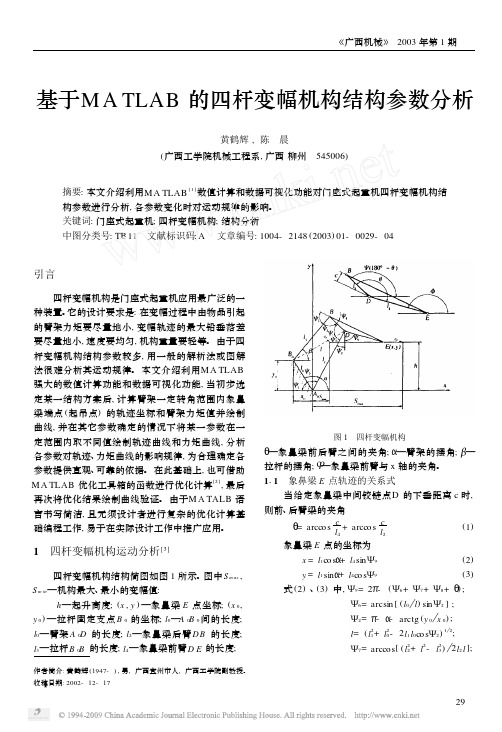
1 四杆变幅机构运动分析[3] 四杆变幅机构结构简图如图1所示。
图中S m ax ,S m in —机构最大、最小的变幅值: h —起升高度;(x ,y )—象鼻梁E 点坐标;(x 0,y 0)—拉杆固定支点B 0的坐标;l 0—A 0B 0间的长度;l 0—臂架A 0D 的长度;l 2—象鼻梁后臂DB 的长度;l 3—拉杆B 0B 的长度;l 4—象鼻梁前臂D E 的长度;图1 四杆变幅机构Η—象鼻梁前后臂之间的夹角;Α—臂架的摆角;Β—拉杆的摆角;Υ—象鼻梁前臂与x 轴的夹角。
基于matlab的平面四连杆机构设计以及该机构的运动分析参考模板
基于matlab的平面四连杆机构设计以及该机构的运动仿真分析摘要四连杆机构因其结构方便灵活,能够传递动力并实现多种运动形式而被广泛应用于各个领域,因此对其进行运动分析具有重要的意义。
传统的分析方法主要应用几何综合法和解析综合法,几何综合法简单直观,但是精确度较低;解析法精确度较高,但是计算工作量大。
随着计算机辅助数值解法的发展,特别是MATLAB软件的引入,解析法已经得到了广泛的应用。
对于四连杆的运动分析,若应用MATLAB 则需要大量的编程,因此我们引入proe软件,我们不仅可以在此软件中建立实物图,而且还可以对其进行运动仿真并对其运动分析。
在设计四连杆时,我们利用解析综合法建立数学模型,再根据数学模型在MATLAB中编程可以求得其他杆件的长度。
针对范例中所求得的各连杆的长度,我们在proe软件中画出其三维图(如图4)并在proe软件中进行仿真分析得出CB,的角加速度的变化,从而得到CB,两接触处所受到的力是成周期性变化的,可以看出CB,两点处的疲劳断裂,我们提B,两点处极易疲劳断裂,针对C出了在设计四连杆中的一些建议。
关键字:解析法 MATLAB 软件 proe 软件 运动仿真建立用解析法设计平面四杆机构模型对于问题中所给出的连架杆AB 的三个位置与连架杆CD 的三个位置相对应,即三组对应位置为:332211,,,,,ψϕψϕψϕ,其中他们对应的值分别为: 52,45,82,90,112,135,为了便于写代数式,可作出AB 与CD 对应的关系,其图如下:图—2 AB 与CD 三个位置对应的关系通过上图我们可以通过建立平面直角坐标系并利用解析法来求解,其直角坐标系图如下:φααi θi φi图—3 平面机构直角坐标系通过建立直角坐标系OXY ,如上图所示,其中0α与0φ为AB 杆与CD 杆的初始角,各杆件的长度分别用矢量d c b a ,,,,表示,将各矢量分别在X 轴与Y 轴上投影的方程为⎩⎨⎧=++=+)sin(*)sin(*)sin(*)cos(*)cos(*)cos(*φθαφθαc b a c d b a在上述的方程中我们可以消除θ,从而可以得到α与φ之间的关系如下:)cos(2)cos(2)cos(2)(2222αφαφab ac cd b d c a +-=+-++ (1) 为便于化简以及matlab 编程我们可以令:⎪⎪⎪⎩⎪⎪⎪⎨⎧==-++=c d H a d H ac b d c a H 32222212 (2) 通过将(2)式代入(1)式中则可以化简得到如下等式: )cos()cos()cos(321αφαφH H H +-=+ (3)我们可以通过(3)式将两连架杆对应的位置带入(3)式中,我们可以得到如下方程:⎪⎩⎪⎨⎧+-=++-=++-=+)cos()cos()cos()cos()cos()cos()cos()cos()cos(333332123222211311121ϕψϕψϕψϕψϕψϕψH H H H H H H H H (4) 联立(4)方程组我们可以求得321,,H H H ,再根据(2)中的条件以及所给定的机架d 的长度,我们可以求出其它杆件的长度为:⎪⎪⎪⎩⎪⎪⎪⎨⎧-++===1222322acH d c a b H d c H d a (5)四连杆设计范例:在日常生活中,我们经常看到消防门总能自动关上,其实它是利用四连杆机构与弹簧组成的。
基于MATLAB软件的铰链四杆机构运动分析仿真软件开发
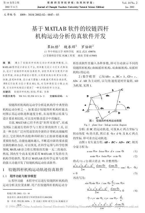
文章编号: 1009-3818(2002)02-0047-03基于MATLAB 软件的铰链四杆机构运动分析仿真软件开发覃虹桥1 魏承辉2 罗佑新2(1华中科技大学材料学院 湖北武汉430074)(2常德师范学院机械工程系 湖南常德415003)摘 要: 建立了铰链四杆机构运动分析的数学模型,以MATLAB 程序设计语言为平台,将参数化设计与交互式相结合,设计了铰链四杆机构仿真软件,该软件具有方便用户的良好界面,并给出界面设计程序,从而使机构分析更加方便、快捷、直观和形象.设计者只需输入参数就可得到仿真结果,再将运行结果与设计要求相比较,对怎样修改设计做出决策.它为四杆机构设计提供了一种实用的软件与方法.关键词: 铰链四杆机构;按钮;界面;仿真中图分类号: TH 311.52;TH 113.2+2 文献标识码: A铰链四杆机构的运动学分析是机构学中典型的机构运动分析之一,如果设计铰链四杆机构时能及时图示其运动轨迹和速度分析,从而将图示结果与设计要求相比较,可以及时修改设计中的偏差.目前,MALTAB 已经不再是/矩阵实验室0,而成为国际上最流行的科学与工程计算的软件工具,以及一种具有广泛应用前景的全新的计算机高级编程语言,它在国内外高校和科研部门正扮演着越来越重要的角色,功能也越来越大,不断适应新的要求提出新的解决办法.可以预见,在科学运算与科学绘图领域,MATLAB 语言将长期保持其独一无二的地位.然而,国内至今尚未见到采用MATLAB 开发的有关机构学的软件,笔者以MATLAB 的科学运算与绘图的强大功能开发了铰链机构运动仿真软件.1 铰链四杆机构运动轨迹仿真软件1.1 程序功能与数学模型1)程序功能 本程序可以进行铰链四杆机构的运动分析及位置求解.用户在铰链四杆机构运动分收稿日期:2002-12-10基金项目:湖南省教育厅科研资助项目(00C289)第一作者:覃虹桥(1959-)男高级工程师研究方向:机械设计制造析仿真软件里输入各种参数,即可自动演示不同的铰链四杆机构(曲柄摇杆机构、双曲柄机构、双摇杆机构)的运动.2)数学模型 已知AB=a ,BC =b ,C D =c ,AD=d .AB 为主动杆,以匀角速度逆时针旋转,AD 为机架,见图1.图1 铰链四杆机构运动简图Fig.1 plame four-linkage motion diagram分析:求B C 的运动轨迹,可找B 、C 两点坐标与转动角度51的关系,然后求51+d 51及B 、C 两点的坐标,即可求出运动轨迹.由图1有矢量方程:AB +BC =AD +DC ,则其分量方程为:a c os 51+b cos 52=d +c cos 53(1)a sin 51+b sin 52=c sin 53(2)将式(1)、(2)联立消去52并整理得:a 2+c 2+d 2-b 22ac +d c os 53a -d cos 51c -cos (51-53)=0(3)再改写为:sin 51sin 53+(cos 51-da)cos 53+a 2+c 2+d 2-b 22ac -d c os 51c=0(4)令r 1=sin 51,r 2=cos 51-d a ,r 2222第14卷第2期常德师范学院学报(自然科学版)Vol.14No.22002年6月Journal of Changde Teachers University(Natural Science Edition)Jun.2002则(4)化为:r 1sin 53+r 2cos 53=r 3(5)由三角恒等式求得:53=2arctg r 1?r 21+r 22-r 23r 2+r 3(6)式(6)两个解对应于机构的两种不同装配形式./+0对应于图1的实线,而/-0对应于图1的虚线.B 点坐标:B x =A x +a cos 51,B y =A y +a sin 51C 点坐示:C x =D x +c cos 53,C y =D y +a sin 53从运动杆的转角53,对时间求导可得DC 的角速度,由式(1)、(2)解出52按速度合成可求得BC 的转动角速度[2].1.2 程序框图以曲柄摇杆机构的运动仿真程度为例,程序框图如下:图2 程序框图Fig.2 Programming frame diagram1.3 程序代码采用MATLAB 开发图形界面,程序如下:%fourlinkages.mh_main=figure(.Units .,.normalized .,.Position .,[.3,.3,.5,.5],,.MenuBar .,.none .,.Name .,.四杆机构仿真.,.Number Title .,,.off .,.Resize .,.off .);h_axis=axes(.Units .,.normalized .,.Position .,[.12,.15,.6,.6],,.Tag .,.axPlot .,.Visible .,.on .,.XLim .,[-50,80<,.YLim .,-60,80]);h_text1=uicontrol (.Style .,.Text .,.Tag .,.myText1.,.Units .,,.normalized .,.Position .,[0.78,0.55,.05,.38],.String .,,.输入已知参数.,,.HorizontalAlignment .,.right .);h_te xt2=uicontrol(.Style .,.Text .,.Tag .,.myText2.,.Units .,,.nor malized .,.Position .,[0.15,0.90,.35,0.05],.String .,,.正在仿真,,OK !.,,.HorizontalAlignment .,.right .);a =20;b =50;c =40;d =50;fai =60;four_linkages0(a,b ,c,fai );%初始化图形h_edit1=uicontrol(.Style .,.Edit .,.Tag .,.myEdit1.,.Units .,,.normalized .,.Position .,[0.86,.85,.10,.1],.String .,.20.,,.HorizontalAlignment .,.right .);h_edit2=uicontrol(.Style .,.Edit .,.Tag .,.myEdit2.,.Units .,,.normalized .,.Position .,[0.86,.75,.10,.1],.String .,.50.,,.HorizontalAlignment .,.right .);h_edit3=uicontrol(.Style .,.Edit .,.Tag .,.myEdit3.,.Units .,,.normalized .,.Position .,[0.86,.65,.10,.1],.String .,.40.,,.HorizontalAlignment .,.right .);h_edit4=uicontrol(.Style .,.Edit .,.Tag .,.myEdit4.,.Units .,,.normalized .,.Position .,[0.86,.55,.10,.1],.String .,.60.,,.HorizontalAlignment .,.right .);h_list=uic ontrol(.Style .,.ListBox .,.Tag .,.myList .,.Units .,,.normalized .,.Position .,[0.78,.35,.20,.15],.String .,.正置|反置.,,.HorizontalAlignment .,.right .,.Value .,1);k=1;h_button1=uicontrol(.Style .,.PushButton .,.Units .,,.normalized .,.Position .,[0.78,.25,.2,.1],.String .,,.运动轨迹仿真.,.CallBack .,,.hd1=findobj(gcf,..Tag ..,..myEdit1..);.,,.a =eval(get(hd1,..String ..));.,,.hd2=findobj(gcf,..Tag ..,..myEdit2..);.,,.b =eval(get(hd2,..String ..));.,,.hd3=findobj(gcf,..Tag ..,..myEdit3..);.,,.c =eval(get(hd3,..String ..));.,,.hd4=findobj(gcf,..Tag ..,..myEdit4..);.,,.d =eval(get(hd4,..String ..));.,,48常德师范学院学报(自然科学版)2002年.kk =get(findobj(gcf,..Ta g ..,..myList ..),..Value ..);.,,.four_linkages(a,b,c,d,kk ).]);%调用回调函数轨迹仿真.h_button2=uicontrol(.Style .,.PushButton .,.Units .,,.normalized .,.Position .,[0.78,.15,.2,.1],.String .,,.角速度分析.,.CallBack .,.four_linkages1(a,b,c,d ,kk ).);h_button3=uicontrol(.Style .,.PushButton .,.Units .,,.normalized .,.Position .,[0.78,.05,.2,.1],,.String .,.退出.,.CallBack .,.four_linkages2.);%调用回调函数退出系统在主程序中有3个回调函数和一个初始化函数,回调函数分别用轨迹仿真、运动分析和退出系统.回调函数程序按前述数学模型编程(程序略);初始化函数用程序运行时初始化界面的图形.运行程序产生以下界面(图3).图3 程序运行界面Fi g.3 Programming Interface在界面中输入已知参数,则可生成相应的图形.当输入a =20,b =50,c =40,d =60,装配形式选取正置时,如果选运动轨迹仿真,则得仿真轨迹(图4);如果装配形式选反置,进行轨迹仿真(图5).(注:图4 运动轨迹仿真(装配形式正置)Fi g.4 Moti on track simulation(positiveset)图5 运动轨迹仿真(装配形式为反置)Fig.5 Motion track simulation (in reverse positive set)在图4、5中为节省篇幅,这两个图形只选了对应图3的图形部分,界面的其它部分未剪取.).而当选取装配形式进行轨迹仿真后,可再选角速度分析,得到连杆与摇杆的角速度图形(略).2 结论1)自动演示不同的四杆机构的运动,模拟仿真运动轨迹与从动件的速度分析,有助于分析机构的速度、加速程度和机构的工作性能;2)采用MATLAB 语言开发机构仿真运动分析软件,开发界面容易,运行程序时无需编辑、连接,给使用者以极大的方便.只要输入数据,即可得到结果.将运行结果与设计要求相比较,从而引导设计者修改设计.参 考 文 献1 薛定宇.科学运算程序MATLAB5.3程序设计与应用[M ].北京:清华大学出版社,2000.2 孟宪源.现代机构手册(上)[M].北京:机械工业出版社,1994.3 王沫然.Si mulink4建模及动态仿真[M].北京:电子工业出版社,2002.THE DEVELOPMENT OF EMULATIONAL SOFTWARE FOR ANALYSIS OF MOTION IN PLANE GEMEL FOUR -LINKAGEBASED ON MATLAB SOFTWAREQING Hong -qiao 1 WEI CH eng -hui 2LU O You -xin 2(1T he material institute,Cen tral China University of Science and T echnology,Wuhan Hubei,430074)(2Department of Mechanical Engineering,Changde Teachers University,Changde Hunan 415003)Abstract A mathematical model of motion analysis was estab -lished in plane four-linkage,and emulational software was deve-loped .The software adop ted Matlab5.3.1as a desi gn language.It combined parametric design with interactive design and had good in -terface for user.Thus,i t was fas ter and more convenient to analyse linkage.The emulational result was obtained as soon as input param -eters was imported and the devisers can make decision-making of modification by the comparing emulational result with design de -mand.It provides an applied software and method for linkage.Key words Gemel Four -Linkage;button;interface;emula -tion(责任编校:谭长贵)49第2期覃虹桥 魏承辉 罗佑新 基于MATLAB 软件的铰链四杆机构运动分析仿真软件开发。
运用MATLAB解决四杆机构问题
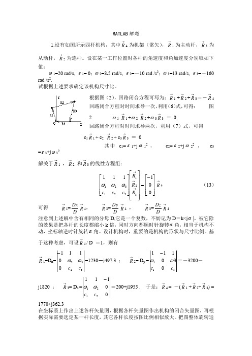
MATLAB 解题1.设有如图所示四杆机构,其中→R 4为机架(常矢),→R1为主动杆,→R3为从动杆,→R 2为连杆。
设在某一工作位置时各杆的角速度和角加速度分别取如下值:ω1=20 rad/s, ε1= 0;ω2=8.5 rad/s, ε2=-10 rad /s 2;ω3=13 rad/s, ε3=-160rad /s 2.试根据上述要求确定该机构尺寸比。
根据图(2),回路闭合方程可写为:→R 1 +→R 2 +→R 3=-→R 4 回路闭合方程对时间求导一次,利用(6)式,可得: 图2 ω1→R 1 +ω2→R 2 +ω3→R 3 = 0回路闭合方程对时间求导两次,利用(7)式,可得c 1→R 1 + c 2 →R 2 + c 3→R 3 = 0其中 c 1=ε1+j ω12 , c 2=ε2+j ω22, c 3=ε3+j ω32解关于→R 1 ,→R 2 和→R 3的线性方程组:⎥⎥⎥⎦⎤⎢⎢⎢⎣⎡-=⎥⎥⎥⎥⎥⎦⎤⎢⎢⎢⎢⎢⎣⎡⎥⎥⎥⎦⎤⎢⎢⎢⎣⎡→→→001111321321321R R R c c c ωωω→R 4 (13) 可得 →R 1=DDx →R 4, →R 2=DDy →R 4 , →R 3=DDz →R 4注意到上述解中含有相同的分母D,它是一个复数,不妨记为D =k<j α|,被它除的效果是把各杆的长度都缩小k 倍,同时方向都顺时针旋转α角,相当于机构不动,坐标轴逆时针旋转α角。
设计机构时,重要的是机构的形状与尺寸比例。
基于这种考虑,可设→R 4 / D =1,则有→R 1=D x =32320111c c ωω-=1230-j497.3 ; →R 2= D y =311030111c c ωω-=-3200-j1820 ; →R 3= D z =001112121c c ωω-=200+j1955 . 于是:→R 4 = -(→R 1 +→R 2+→R 3) = 1770+j362.3在坐标系上作出上述各杆矢量图,根据各杆矢量图作出机构的闭合矢量图,再根据实际需要选定某一杆长度,其它各杆长度按图比例相似放大。
基于matlab的平面四杆机构运动分析_毕业论文

……………………. ………………. …………………毕业论文基于MATLAB的平面四杆机构运动分析院部机械与电子工程学院装订线……………….……. …………. …………. ………摘要 (I)Abstract (II)1 绪论 (1)2 平面四杆机构运动分析 (2)2.1 平面四杆机构简介 (2)2.2 平面四杆机构类型分析 (3)2.3 建立平面四杆机构的数学模型 (4)2.3.1 建立平面四杆机构的封闭矢量位置方程式 (4)2.3.2 运用矢量法和矩阵法求解封闭矢量方程式 (5)2.3.3 求解过程涉及的数学、物理计算方法 (6)3 基于MATLAB 的运动分析程序设计 (7)3.1 MATLAB简介 (7)3.2 程序设计流程 (8)3.3 编写程序的M文件 (10)3.3.1编写fun函数 (10)3.3.2编写主程序 (10)3.4 程序运行输出结果 (12)4 基于MATLAB的GUI分析系统设计 (15)4.1 GUI简介 (15)4.2 GUI界面设计 (15)4.3 GUI代码编写 (16)4.3.1 Edit Text代码编写 (16)4.3.2 Pop-up Menu代码编写 (16)4.4 GUI分析系统运行效果 (17)5 结论 (18)参考文献 (20)致谢 (20)附录 (20)附录一主函数程序代码 (20)附录二popupmenu4_Callback函数下程序代码 (23)Abstract (II)1 Introduction (1)2 The analysis of motion for planar four-bar mechanism (2)2.1 Intoduction to the planar four-bar mechanism (2)2.2 Analysis for the types of planar four-bar mechanism (3)2.3 Build the mathematical model of planar four-bar mechanism (4)2.3.1 Build the closed position vector equation for planar four-bar mechanism (4)2.3.2 Apply the vector & matrix method to solve the closed vector equation (4)2.3.3 Mathematical & physical calculation method involved in the solving process (5)3 The program design for the motion analysis based on MATLAB (7)3.1 Introduction to MATLAB (7)3.2 The program design process (7)3.3 Write the M-file for program (9)3.3.1 Write the fun function (9)3.3.2 Write the main function (9)3.4 The output of running the program (11)4 The design of GUI analysis system based on MATLAB (14)4.1 Introducton to GUI (14)4.2 The interface design of GUI (14)4.3 Write the GUI code (15)4.3.1 Write the Edit Text code (15)4.3.2 Write the Pop-up Menu code (15)4.4 The running effect of the GUI analysis system (16)5 Conclusion (19)References (20)Acknowledgement (21)Appendix (22)Appendix I The main function code (22)Appendix II The popupmenu4_Callback function code (25)基于MATLAB的平面四杆机构运动分析摘要:建立以平面四杆机构为研究对象的数学模型,以MATLAB软件为载体,利用MATLAB矩阵数据分析处理功能,设计了平面四杆机构运动分析程序。
基于MATLAB的液压支架四连杆机构的力学分析
参考文献 1. 黄 滨, 王 秦辉. 优 化课程 结构 的探 索与实 践[ J] . 教 书育 人, 2002
155
三、结语 总之, 对于 变电站 的自 动化 系统, 要 充分 掌握 接地 干扰 的途径、原理、以及可能会受干扰 的设备, 并针 对他们 采取有 效地预防措施。通过 这些 有效 的措 施保 证变 电站 的自 动化 系统的安全、高效的运行 。变电 站的自 动化系 统是一 个复杂 的系统, 在实际的运行当 中, 要结 合实际 情况, 不断地 进行改 造、完善, 以确保变电站能够安全的生产。
154
标函数对支架四连杆机构进行优化设计。 一、输入液压支架基本参数 在进行液压支架四连杆机构优 化设计时 , 首 先要根 据四
连杆液压支架尺寸 结构 确立 科学 合理 的数 学模 型。参照 简 图根据实际工况的 条件和 四连 杆的几 何运 动轨 迹把 合理 的 参数输入到图 1 中, 如 图 1 所示。 也 可以 用 导入 按 钮在 . txt 格式的文件中直接 导入数 值, 最后 运算合 理的 数值可 通 过导出按钮直接导出到 . txt 格式的文件中保存。
MATLAB的曲柄滑块和四杆机构的综合设计解析
KUNMING UNIVERSITY OF SCIENCE AND TECHNOLOGY《计算机仿真技术》课程设计报告冯叶/ 浦合旳201410302544/ 201410302547刘孝保2015年6月姓名: 学号: 专业班级: 指导教师:机械卓目录©区肌理乂殳申KUMWBG sngn OF SCIENCE MO TCCWlOGr目录1 •仿真问题描述.........................................................................2•仿真问题数学模型......................................................................3. Mat lab实现方法 .....................................................................4・Mat lab代码..........................................................................5•仿真结论..............................................................................6.遇到的问题和解决的方式.................................................................7 •课程学习意见与建议...................................................................《计算机仿真技术》课程设计报告 艮咽疗N 乂孝 ItnVH ; WmJSTY :f SCOtCE MP TOCtXCCf 1 •仿真问题描述已知机架AD 长为L1,曲柄AB 长为L2,连杆BC 长L3,另一机架长CD 长为L4,与AB 杆相 连的是一滑块E 。
基于MATLAB的平面四连杆机构运动学分析

一、课程设计容及要求:1.对连杆机构运动工作原理及运动参数有一定理解2.掌握MATLAB基本命令3.了解MATLAB编程的基本知识,并能编写简单M文件4.了解MATLAB图形界面设计的基本知识5.课程设计说明书:应阐述整个课程设计容,要突出重点和特色,图文并茂,文字通畅。
应有目录、摘要及关键词、正文、参考文献等容,字数一般不少于6000字。
二、主要参考资料有关复杂刀具参数计算及结构设计、机械制造工艺与设备的手册与图册。
三、课程设计进度安排指导教师(签名):时间:教研室主任(签名):时间:院长(签名):时间:目录1平面连杆机构的运动分析 (1)1.1 机构运动分析的任务、目的和方法 (1)1.2 机构的工作原理 (1)1.3 机构的数学模型的建立 (1)1.3.1建立机构的闭环矢量位置方程 (1)1.3.2求解方法 (2)2 基于MATLAB程序设计 (4)2.1 程序流程图 (4)2.2 M文件编写 (6)2.3 程序运行结果输出 (7)3 基于MATLAB图形界面设计 (11)3.1界面设计 (11)3.2代码设计 (12)4 小结 (17)参考文献 (18)1平面连杆机构的运动分析1.1 机构运动分析的任务、目的和方法曲柄摇杆机构是平面连杆机构中最基本的由转动副组成的四杆机构,它可以用来实现转动和摆动之间运动形式的转换或传递动力。
对四杆机构进行运动分析的意义是:在机构尺寸参数已知的情况下,假定主动件(曲柄)做匀速转动,撇开力的作用,仅从运动几何关系上分析从动件(连杆、摇杆)的角位移、角速度、角加速度等运动参数的变化情况。
还可以根据机构闭环矢量方程计算从动件的位移偏差。
上述这些容,无论是设计新的机械,还是为了了解现有机械的运动性能,都是十分必要的,而且它还是研究机械运动性能和动力性能提供必要的依据。
机构运动分析的方法很多,主要有图解法和解析法。
当需要简捷直观地了解机构的某个或某几个位置的运动特性时,采用图解法比较方便,而且精度也能满足实际问题的要求。
基于matlab GUI的平面四杆机构的运动分析

基于matlab GUI的平面四杆机构的运动分析一、目的通过matlab对平面四杆机构进行运动仿真,并以GUI界面方式实现输入输出的参数化,对平面四杆机构进行位置分析、速度分析、加速度分析和静力学分析。
此外,通过动画演示,更加形象直观地观察机构的运动过程。
最后,将程序编译成.exe独立可执行文件,可以在其它没有安装matlab的机器上运行。
二、设计思路通过matlab的GUI功能模块,创建一个图形用户界面,在自动生成的代码框架中对初始化函数和回调函数等进行编辑,建立与控件相关联的程序:控件属性、位置分析、速度分析、加速度分析、静力学分析、动画演示等。
图1是平面四杆机构的示意图,输入角q的运动规律为q=pi/50*t^2+q0,r1、r2是从动角。
对t时刻沿着杆长距离原点A的任意一点进行分析。
注意:输入输出角的单位为度,时间t的取值范围为0:0.05:10,任意点lx的取值范围为0~a1+a2+a3,估算的从动角r1、r2的迭代初始值不能偏离平衡位置太大。
图1、平面四杆机构示意图三、设计流程1、通过GUI模块创建图形用户界面命令方式:在Matlab命令窗口键入>>guide;菜单方式:在Matlab的主窗口中,选择File>New>GUI命令,就会显示GUI的设计模板。
如图1所示。
图2、创建图形界面2、设计图形界面在创建之后的图形界面中插入坐标轴axes,静态文本框static text,编辑文本框edit text,按钮push button等等。
如图所示。
图3、图形界面设计3、编辑回调函数1)位置分析:输入角的函数为:q=pi/50*t^2+q0。
在时间t=0~10s内,每一个时间点估算两个初始从动角,根据牛顿-拉普森迭代得到准确的机构位置。
10s刚好主动角经历了360度,记录每一时刻的位置,便可以动画演示。
2)速度分析:输入角速度为:dq=pi/25*t。
选择杆件上的任意一点(坐标表示为质点沿着杆件到原点A的距离)做分析,正确表达出角速度系数和速度系数,便可以求出质点的速度。
Matlab在四杆机构运动分析中的应用
Matlab在四杆机构运动分析中的应用MATLAB软件由美国MathWorks公司于1982年推出,经过十几年的发展和竞争,现已成为国际公认的最优秀的科技应用软件之一。
MATLAB提供了强大的矩阵处理和绘图功能。
它主要包括两部分内容:核心函数和工具箱。
Matlab编程代码接近数学推导公式,简洁直观,与科技人员的思维方式和书写习惯相适应,操作简易,人机交互性能好,且可以方便迅速地用三维图形、图像、声音、动画等表达计算结果,拓展思路。
编制相应的M函数文件。
Pos.m用于求解位置、角度和角加速度。
th1为初始角度,w1为杆1角速度,其余为杆长。
将课本P35(i)、(ii)、(iii)式用MATLAB语言表述,即可编制为四杆机构求解函数文件pos.m。
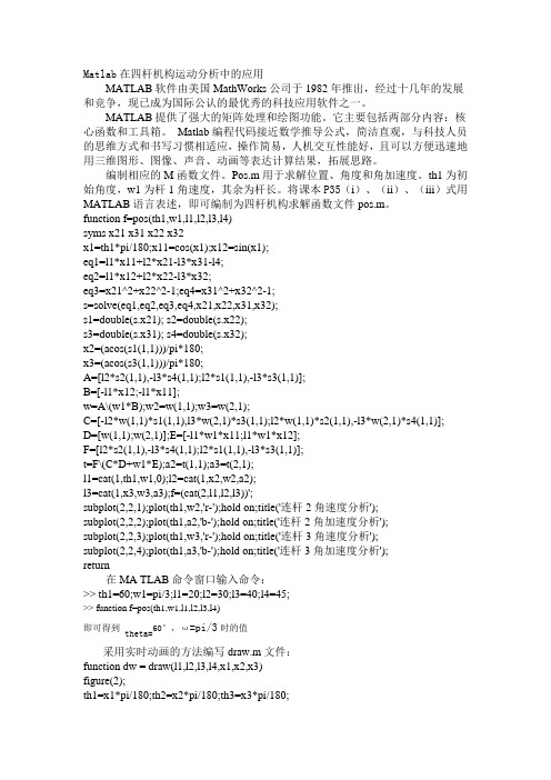
function f=pos(th1,w1,l1,l2,l3,l4)syms x21 x31 x22 x32x1=th1*pi/180;x11=cos(x1);x12=sin(x1);eq1=l1*x11+l2*x21-l3*x31-l4;eq2=l1*x12+l2*x22-l3*x32;eq3=x21^2+x22^2-1;eq4=x31^2+x32^2-1;s=solve(eq1,eq2,eq3,eq4,x21,x22,x31,x32);s1=double(s.x21); s2=double(s.x22);s3=double(s.x31); s4=double(s.x32);x2=(acos(s1(1,1)))/pi*180;x3=(acos(s3(1,1)))/pi*180;A=[l2*s2(1,1),-l3*s4(1,1);l2*s1(1,1),-l3*s3(1,1)];B=[-l1*x12;-l1*x11];w=A\(w1*B);w2=w(1,1);w3=w(2,1);C=[-l2*w(1,1)*s1(1,1),l3*w(2,1)*s3(1,1);l2*w(1,1)*s2(1,1),-l3*w(2,1)*s4(1,1)];D=[w(1,1);w(2,1)];E=[-l1*w1*x11;l1*w1*x12];F=[l2*s2(1,1),-l3*s4(1,1);l2*s1(1,1),-l3*s3(1,1)];t=F\(C*D+w1*E);a2=t(1,1);a3=t(2,1);l1=cat(1,th1,w1,0);l2=cat(1,x2,w2,a2);l3=cat(1,x3,w3,a3);f=(cat(2,l1,l2,l3))';subplot(2,2,1);plot(th1,w2,'r-');hold on;title('连杆2角速度分析');subplot(2,2,2);plot(th1,a2,'b-');hold on;title('连杆2角加速度分析');subplot(2,2,3);plot(th1,w3,'r-');hold on;title('连杆3角速度分析');subplot(2,2,4);plot(th1,a3,'b-');hold on;title('连杆3角加速度分析');return在MA TLAB命令窗口输入命令:>> th1=60;w1=pi/3;l1=20;l2=30;l3=40;l4=45;>> function f=pos(th1,w1,l1,l2,l3,l4)60°,ω=pi/3时的值即可得到theta=采用实时动画的方法编写draw.m文件:function dw = draw(l1,l2,l3,l4,x1,x2,x3)figure(2);th1=x1*pi/180;th2=x2*pi/180;th3=x3*pi/180;x=0:0.001:l4;plot(x,0,'r-');axis([-25,70,-25,60]);hold onfor i=0:0.1:l1;s=i*cos(th1); c=i*sin(th1);plot(s,c,'b-');hold on;end;for x=0:0.1:l3;s2=x*cos(th3)+l4;c2=x*sin(th3);plot(s2,c2);hold on;endfor x=0:0.1:l2;s3=l1*cos(th1)+x*cos(th2); c3=l1*sin(th1)+x*sin(th2);plot(s3,c3);hold on;endreturn代入pos.m中所得的结果,输入命令:>>draw(l1,l2,l3,l4,y(1,1),y(2,1),y(3,1))即可得到当前位置下的四杆图形。
基于Matlab的四杆机构优化设计简介

·制造业信息化·Vol.22.,200922009机电产品开发与创新Development &Innovation of M achinery &E lectrical P roducts3,No.1Jan .,2010第23卷第1期2010年1月收稿日期:2009-11-06作者简介:李建霞,女,河南信阳人,教授。
主要从事计算机辅助设计教学与研究工作。
已发表核心期刊论文20余篇;王良才,男,山东济南人,副教授。
主要从事机械设计教学与研究工作。
已发表核心期刊论文10余篇。
0引言Matlab 语言是一种非常强大的工程计算语言,提供了非常丰富的Matlab 优化工具箱。
其优化工具箱有许多常用的优化算法,广泛应用于线性规划、二次规划、非线性优化、最小二乘法问题、非线性方程求解、多目标决策等问题,其函数表达简洁,优化算法选择灵活,参数设置自由,相比于其它很多成熟的优化程序具有明显的优越性。
机械优化设计是在现代机械设计理论发展基础上产生的一种新的设计方法,在机械零部件设计中取得了广泛的应用。
机械优化设计是在进行某种机械产品设计时,根据规定的约束条件,优选设计参数,使某项或几项设计指标获得最优值。
在进行优化设计时,首先要建立工程设计问题的数学模型,然后按照数学模型的特点选择优化方法及其计算程序,求得最优设计方案。
1四杆机构优化设计的数学模型四杆机构是机械传动的重要组成部分。
设计四杆机构通常使用作图法与实验法,这两种方法简单易行,但误差较大,运用解析法,能获得所要求的精度,然而用人工进行,整个设计过程是一项繁琐、冗长的工作,甚至可能无法实现。
采用Matlab 优化工具箱对四杆机构进行优化设计,不仅参数输入简单,而且编程工作量小,可更快捷准确地达到设计要求。
四杆机构种类很多,这里只以曲柄摇杆机构为例说明四杆机构优化设计方法。
Matlab 优化工具箱是一套功能强大的工程计算软件,集数值计算、符号运算、可视化建模、仿真和图形处理等多种功能于一体,被广泛应用于机械设计、自动控制和数理统计等工程领域。
《有限元基础教程》_【MATLAB算例】3.2.5(2)__四杆桁架结构的有限元分析(Bar2D2Node)

【MATLAB 算例】3.2.5(2) 四杆桁架结构的有限元分析(Bar2D2Node)如图3-8所示的结构,各个杆的弹性模量和横截面积都为4229.510/E N mm =⨯, 2100A mm =。
试基于MATLAB 平台求解该结构的节点位移、单元应力以及支反力。
图3-8 四杆桁架结构解答:对该问题进行有限元分析的过程如下。
(1) 结构的离散化与编号对该结构进行自然离散,节点编号和单元编号如图3-8所示,有关节点和单元的信息见表3-1~表3-3。
(2)计算各单元的刚度矩阵(基于国际标准单位)建立一个工作目录,将所编制的用于平面桁架单元分析的4个MA TLAB 函数放置于该工作目录中,分别以各自函数的名称给出文件名,即:Bar2D2Node_Stiffness ,Bar2D2Node_Assembly ,Bar2D2Node_Stress ,Bar2D2Node_Forces 。
然后启动MATLAB ,将工作目录设置到已建立的目录中,在MATLAB 环境中,输入弹性模量E 、横截面积A ,各点坐标x1,y1,x2,y2,x3,y3,x4,y4,角度alpha 1, alpha 2和alpha 3,然后分别针对单元1,2,3和4,调用4次Bar2D2Node_Stiffness ,就可以得到单元的刚度矩阵。
相关的计算流程如下。
>>E=2.95e11;>>A=0.0001;>>x1=0;>>y1=0;>>x2=0.4;>>y2=0;>>x3=0.4;>>y3=0.3;>>x4=0;>>y4=0.3;>> alpha1=0;>> alpha2=90;>> alpha3=atan(0.75)*180/pi;>> k1=Bar2D2Node_Stiffness (E,A,x1,y1,x2,y2,alpha1)k1 = 73750000 0 -73750000 00 0 0 0-73750000 0 73750000 00 0 0 0>> k2=Bar2D2Node_Stiffness (E,A,x2,y2,x3,y3,alpha2)k2 = 1.0e+007 *0.0000 0.0000 -0.0000 -0.00000.0000 9.8333 -0.0000 -9.8333-0.0000 -0.0000 0.0000 0.0000-0.0000 -9.8333 0.0000 9.8333>> k3=Bar2D2Node_Stiffness (E,A,x1,y1,x3,y3,alpha3)k3 = 1.0e+007 *3.7760 2.8320 -3.7760 -2.83202.8320 2.1240 -2.8320 -2.1240-3.7760 -2.8320 3.7760 2.8320-2.8320 -2.1240 2.8320 2.1240>> k4=Bar2D2Node_Stiffness (E,A,x4,y4,x3,y3,alpha1)k4 = 73750000 0 -73750000 00 0 0 0-73750000 0 73750000 00 0 0 0(3) 建立整体刚度方程由于该结构共有4个节点,因此,设置结构总的刚度矩阵为KK (8×8),先对KK 清零,然后四次调用函数Bar2D2Node _Assembly 进行刚度矩阵的组装。
matlab四连杆带代码

用M a t l a b对四连杆运动模拟引言四连杆机构因其结构灵活、能够传递动力并有效地实现预定动作,在很多领域得到了广泛应用。
进行连杆机构运动分析,传统方法主要是图解法或分析法,无论设计精度还是设计效率都相对低下,无法满足现代机械高速高精度的要求。
随着计算机技术的飞速发展,特别是以MATLAB为代表的数值计算软件的出现,为进行机构分析提供了有力的工具。
1、四连杆介绍1.1、四连杆介绍与分类所有运动副均为转动副的四杆机构称为铰链四杆机构,它是平面四杆机构的基本形式,其他四杆机构都可以看成是在它的基础上演化而来的。
选定其中一个构件作为机架之后,直接与机架链接的构件称为连架杆,不直接与机架连接的构件称为连杆,能够做整周回转的构件被称作曲柄,只能在某一角度范围内往复摆动的构件称为摇杆。
如果以转动副连接的两个构件可以做整周相对转动,则称之为整转副,反之称之为摆转副。
铰链四杆机构中,按照连架杆是否可以做整圆周转动,可以将其分为三种基本形式,即曲柄摇杆机构,双曲柄机构和双摇杆机构。
曲柄摇杆机构,两连架杆中一个为曲柄一个为摇杆的铰链四杆机构。
双曲柄机构,具有两个曲柄的铰链四杆机构称为双曲柄机构。
其特点是当主动曲柄连续等速转动时,从动曲柄一般做不等速转动。
在双曲柄机构中,如果两对边构件长度相等且平行,则成为平行四边形机构。
这种机构的传动特点是主动曲柄和从动曲柄均以相同的角速度转动,而连杆做平动。
双摇杆机构。
双摇杆机构是两连架杆均为摇杆的铰链四杆机构。
1.2、格拉霍夫定理杆长之和条件:平面四杆机构的最短杆和最长杆的长度之和小于或者等于其余两杆长度之和。
在铰链四杆机构中,如果某个转动副能够成为整转副,则它所连接的两个构件中,必有一个为最短杆,并且四个构件的长度关系满足杆长之和条件。
在有整装副存在的铰链四杆机构中,最短杆两端的转动副均为整转副。
此时,如果取最短杆为机架,则得到双曲柄机构;若取最短杆的任何一个相连构件为机架,则得到曲柄摇杆机构;如果取最短杆对面构件为机架,则得到双摇杆机构。
- 1、下载文档前请自行甄别文档内容的完整性,平台不提供额外的编辑、内容补充、找答案等附加服务。
- 2、"仅部分预览"的文档,不可在线预览部分如存在完整性等问题,可反馈申请退款(可完整预览的文档不适用该条件!)。
- 3、如文档侵犯您的权益,请联系客服反馈,我们会尽快为您处理(人工客服工作时间:9:00-18:30)。
首先创建函数FoutBarPosition,函数fsolve通过他确定。
function t=fourbarposition(th,th2,L2,L3,L4,L1)t=[L2*cos(th2)+L3*cos(th(1))-L4*cos(th(2))-L1;…L2*sin(th2)+L3*sin(th(1))-L4*sin(th(2))];主程序如下:disp ' * * * * * * 平面四杆机构的运动分析* * * * * *'L1=304.8;L2=101.6;L3=254.0;L4=177.8; %给定已知量,各杆长L1,L2,L3,L4th2=[0:1/6:2]*pi; %曲柄输入角度从0至360度,步长为pi/6th34=zeros(length(th2),2); %建立一个N行2列的零矩阵,第一列存放options=optimset('display','off'); %θ_3,第二列存放θ_3for m=1:length(th2) %建立for循环,求解θ_3,θ_4th34(m,:)=fsolve('fourbarposition',[1 1],…%调用fsove函数求解关于θ_3,θ_4options,th2(m),L2,L3,L4,L1); %的非线性超越方程,结果保存在th34中endy=L2*sin(th2)+L3*sin(th34(:,1)'); %连杆3的D端点Y坐标值x=L2*cos(th2)+L3*cos(th34(:,1)'); %连杆3的D端点X坐标值xx=[L2*cos(th2)]; %连杆3的C端点X坐标值yy=[L2*sin(th2)]; %连杆3的C端点Y坐标值figure(1)plot([x;xx],[y;yy],'k',[0 L1],[0 0],…%绘制连杆3的几个位置点'k--^',x,y,'ko',xx,yy,'ks')title('连杆3的几个位置点')xlabel('水平方向')ylabel('垂直方向')axis equal %XY坐标均衡th2=[0:2/72:2]*pi; %重新细分曲柄输入角度θ_2,步长为5度th34=zeros(length(th2),2);options=optimset('display','off');for m=1:length(th2)th34(m,:)=fsolve('fourbarposition',[1 1],…options,th2(m),L2,L3,L4,L1);endfigure(2)plot(th2*180/pi,th34(:,1),th2*180/pi,th34(:,2)) %绘制连杆3的角位移关于曲柄2的角位移图plot(th2*180/pi,th34(:,1)*180/pi,…th2*180/pi,th34(:,2)*180/pi) %绘制摇杆4的角位移关于曲柄2的角位移图axis([0 360 0 170]) %确定XY边界值grid %图形加网格xlabel('主动件转角\theta_2(度)')ylabel('从动件角位移(度)')title('角位移线图')text(120,120,'摇杆4角位移')text(150,40,'连杆3角位移')w2=250; %设定曲柄角速度for i=1:length(th2)A=[-L3*sin(th34(i,1)) L4*sin(th34(i,2));…L3*cos(th34(i,1)) -L4*cos(th34(i,2))];B=[w2*L2*sin(th2(i)); -w2*L2*cos(th2(i))];w=inv(A)*B;w3(i)=w(1);w4(i)=w(2);endfigure(3)plot(th2*180/pi,w3,th2*180/pi,w4); %绘制角速度线图axis([0 360 -175 200])text(50,160,'摇杆4角速度(\omega_4)')text(220,130,'连杆3角速度(\omega_3)')gridxlabel('主动件转角\theta_2(度)')ylabel('从动件角速度(rad\cdot s^{-1})')title('角速度线图')for i=1:length(th2)C=[-L3*sin(th34(i,1)) L4*sin(th34(i,2));…L3*cos(th34(i,1)) -L4*cos(th34(i,2))];D=[w2^2*L2*cos(th2(i))+w3(i)^2*L3*cos(th34(i,1))-w4(i)^2*L4*cos(th34(i,2));...w2^2*L2*sin(th2(i))+w3(i)^2*L3*sin(th34(i,1))-w4(i)^2*L4*sin(th34(i,2))];a=inv(C)*D;a3(i)=a(1);a4(i)=a(2);endfigure(4)plot(th2*180/pi,a3,th2*180/pi,a4); %绘制角加速度线图axis([0 360 -70000 65000])text(50,50000,'摇杆4角加速度(\alpha_4)')text(220,12000,'连杆3角加速度(\alpha_3)')gridxlabel('从动件角加速度')ylabel('从动件角加速度(rad\cdot s^{-2})')title('角加速度线图')disp '曲柄转角连杆转角-摇杆转角-连杆角速度-摇杆角速度-连杆加速度-摇杆加速度' ydcs=[th2'*180/pi,th34(:,1)*180/pi,th34(:,2)*180/pi,w3',w4',a3',a4'];disp(ydcs)>> * * * * * * 平面四杆机构的运动分析* * * * * *曲柄转角连杆转角-摇杆转角-连杆角速度-摇杆角速度-连杆加速度-摇杆加速度1.0e+004 *0 0.0044 0.0097 -0.0125 -0.0125 -0.5478 4.84580.0005 0.0042 0.0094 -0.0126 -0.0107 0.2300 5.5630 0.0010 0.0039 0.0092 -0.0124 -0.0086 0.8946 6.0520 0.0015 0.0037 0.0091 -0.0119 -0.0065 1.4143 6.2982 0.0020 0.0034 0.0090 -0.0114 -0.0043 1.7801 6.3174 0.0025 0.0032 0.0089 -0.0107 -0.0021 2.0027 6.1467 0.0030 0.0030 0.0089 -0.0100 0.0000 2.1046 5.8339 0.0035 0.0028 0.0089 -0.0093 0.0020 2.1134 5.4272 0.0040 0.0026 0.0090 -0.0085 0.0038 2.0566 4.9687 0.0045 0.0025 0.0091 -0.0078 0.0054 1.9578 4.4918 0.0050 0.0023 0.0092 -0.0072 0.0069 1.8356 4.0198 0.0055 0.0022 0.0093 -0.0065 0.0082 1.7040 3.5680 0.0060 0.0021 0.0095 -0.0060 0.0094 1.5725 3.1450 0.0065 0.0019 0.0097 -0.0055 0.0104 1.4474 2.7545 0.0070 0.0018 0.0099 -0.0050 0.0113 1.3328 2.3968 0.0075 0.0017 0.0102 -0.0045 0.0121 1.2307 2.0702 0.0080 0.0017 0.0104 -0.0041 0.0128 1.1425 1.7716 0.0085 0.0016 0.0107 -0.0037 0.0134 1.0687 1.4971 0.0090 0.0015 0.0110 -0.0034 0.0138 1.0095 1.2426 0.0095 0.0014 0.0112 -0.0030 0.0142 0.9653 1.0035 0.0100 0.0014 0.0115 -0.0027 0.0145 0.9364 0.7752 0.0105 0.0013 0.0118 -0.0024 0.0148 0.9232 0.5530 0.0110 0.0013 0.0121 -0.0020 0.0149 0.9269 0.3319 0.0115 0.0013 0.0124 -0.0017 0.0150 0.9485 0.1069 0.0120 0.0012 0.0127 -0.0014 0.0150 0.9899 -0.1276 0.0125 0.0012 0.0130 -0.0010 0.0149 1.0530 -0.3773 0.0130 0.0012 0.0133 -0.0006 0.0147 1.1404 -0.6481 0.0135 0.0012 0.0136 -0.0002 0.0145 1.2544 -0.9455 0.0140 0.0012 0.0139 0.0002 0.0141 1.3967 -1.2743 0.0145 0.0012 0.0142 0.0008 0.0136 1.5677 -1.63680.0150 0.0012 0.0144 0.0013 0.0129 1.7648 -2.0314 0.0155 0.0012 0.0147 0.0020 0.0121 1.9807 -2.4495 0.0160 0.0013 0.0149 0.0027 0.0112 2.2018 -2.8735 0.0165 0.0013 0.0151 0.0035 0.0101 2.4071 -3.2754 0.0170 0.0014 0.0153 0.0044 0.0089 2.5697 -3.6186 0.0175 0.0015 0.0155 0.0053 0.0076 2.6616 -3.8650 0.0180 0.0016 0.0156 0.0063 0.0063 2.6609 -3.9849 0.0185 0.0018 0.0157 0.0072 0.0049 2.5591 -3.9674 0.0190 0.0019 0.0158 0.0080 0.0035 2.3638 -3.8244 0.0195 0.0021 0.0159 0.0088 0.0022 2.0959 -3.5866 0.0200 0.0023 0.0159 0.0095 0.0010 1.7823 -3.2931 0.0205 0.0025 0.0159 0.0100 -0.0001 1.4487 -2.9815 0.0210 0.0027 0.0159 0.0105 -0.0011 1.1152 -2.6809 0.0215 0.0029 0.0159 0.0108 -0.0020 0.7942 -2.4103 0.0220 0.0031 0.0158 0.0111 -0.0028 0.4916 -2.1794 0.0225 0.0033 0.0158 0.0112 -0.0035 0.2086 -1.9913 0.0230 0.0036 0.0157 0.0112 -0.0042 -0.0565 -1.8450 0.0235 0.0038 0.0156 0.0111 -0.0048 -0.3071 -1.7375 0.0240 0.0040 0.0155 0.0110 -0.0054 -0.5475 -1.6650 0.0245 0.0042 0.0154 0.0108 -0.0060 -0.7817 -1.6233 0.0250 0.0044 0.0153 0.0104 -0.0065 -1.0139 -1.6089 0.0255 0.0046 0.0151 0.0100 -0.0071 -1.2479 -1.6181 0.0260 0.0048 0.0150 0.0096 -0.0077 -1.4868 -1.6480 0.0265 0.0050 0.0148 0.0090 -0.0082 -1.7336 -1.6955 0.0270 0.0052 0.0146 0.0084 -0.0088 -1.9905 -1.7574 0.0275 0.0054 0.0145 0.0076 -0.0095 -2.2588 -1.8304 0.0280 0.0055 0.0143 0.0068 -0.0101 -2.5391 -1.9100 0.0285 0.0056 0.0141 0.0058 -0.0108 -2.8305 -1.9910 0.0290 0.0057 0.0138 0.0048 -0.0115 -3.1300 -2.06600.0295 0.0058 0.0136 0.0037 -0.0122 -3.4326 -2.1255 0.0300 0.0059 0.0133 0.0024 -0.0130 -3.7297 -2.1572 0.0305 0.0059 0.0131 0.0011 -0.0137 -4.0091 -2.1451 0.0310 0.0059 0.0128 -0.0004 -0.0145 -4.2538 -2.0696 0.0315 0.0059 0.0125 -0.0019 -0.0152 -4.4419 -1.9079 0.0320 0.0058 0.0122 -0.0035 -0.0158 -4.5473 -1.6352 0.0325 0.0058 0.0119 -0.0051 -0.0163 -4.5411 -1.2273 0.0330 0.0056 0.0115 -0.0066 -0.0166 -4.3954 -0.6661 0.0335 0.0055 0.0112 -0.0081 -0.0167 -4.0889 0.0551 0.0340 0.0053 0.0109 -0.0095 -0.0166 -3.6129 0.9243 0.0345 0.0051 0.0105 -0.0106 -0.0161 -2.9781 1.9058 0.0350 0.0049 0.0102 -0.0115 -0.0152 -2.2178 2.9395 0.0355 0.0047 0.0099 -0.0122 -0.0140 -1.3857 3.9473 0.0360 0.0044 0.0097 -0.0125 -0.0125 -0.5478 4.8458 图形输出:图2 连杆3的几个位置点图4 角加速度线图图5 角加速度线图。