充电模块说明书
tt2-t充电模块说明书

一、 整流模块简介TT 系列电力专用高频开关整流模块采用先进的谐振式软开关技术;专门针对各类变电站、电厂及其他直流供电场合的直流屏而设计。
TT 系列整流模块采用智能风冷的散热方式,具有高效率,高密度,高功率因数、高可靠性等特点,同时具有造型美观、占用空间少;采用2U*4U 标准设计,内置防倒灌二极管,方便客户组屏。
TT 系列总包括4款型号:TT11010-T/TT22005-T/TT11020-T/TT22010-T; 4款整流模块采用统一外观,统一机箱,统一开孔尺寸,方便客户选型设计。
整流模块型号说明见下图:TT22010-T 整理模块型号说明工作原理:整流模块工作原理图如下所示:交流输入 直流输出485通信输入EMI PFC DC/DC 整流滤波 输出EMI输入检测和保护 辅助电源 输出检测 温度检测 DC/DC 保护控制监控模块二、外观及接口1.整流模块外观TT22010-T整流模块外观2.前面板TT22010-T整流模块前面板1)LED指示灯(红色)故障指示灯灭 亮输出欠压保护E36 风扇故障E37 (具体信心参见故障代码)2) 数码管可显示模块电压、电流、地址、告警等信息。
若按键无操作超过大约30秒后,将自动显示模块电压,此时如果存在告警,则显示故障代码。
电压显示精度为±1V ,电流显示精度为±。
3) 微调旋钮由于不同用户现在蓄电池的节数有差异,可以通过拨码开关设置整流模块为手动调压时,整流模块输出电压自动调整到出厂设定值235V(标称220V 模块)或121V (标称110V 模块),为了安全起见,非专业人员请勿操作。
4) 显示按钮默认为显示电压,按下时依次显示输出电压、输出电流、模块地址。
5) 拨码开关设置拨码开关用于设置整流模块的控制方式、模块组号、模块地址,1号为最低位,4号为最高位。
模块地址设置请参照下表:二进制与十进制对应关系表0 1模块地址 (0~15) 模块组号 (1~2)控制模式(ON:手动、OFF:自动)二进制0000000100100011010001010110011110001001101010111100110111101111十进制0123456789101112131415整流模块地址通过拨码开关1234号位设置地址,可设置范围为0~15,亦即每组整流模块的最大并机数为15个。
KT-8001 无线供电、充电模块 说明书
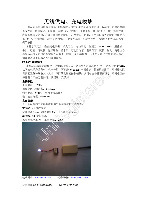
无线供电、充电模块
本品为最新科研技术成果,世界首款面向广大生产企业方便实用于各种电子电器产品的无线充电、供电模块。
效率高、体积小巧、重量轻、价格低廉、使用寿命长、使用简单方便,收发均实现全密封,在水下也可照常给电子产品供电、充电,可穿透电器外壳给内部电路充电、供电;并陆续推出适用于各种电子、电器产品大、小功率模块,以满足各种产品的需要。
适用范围:
各种水下用品、全密封电子表、成人用品、电动牙刷、剃须刀、MP3、MP4、照像机、手机、电脑、电视机、厨房用品、潜水泵、电动自行车、电动汽车、航模、玩具、高电压器件等各种电子电器产品实现全面防水、防潮,免机械接触,大大延才电子产品的使用寿命,彻底解决电子电器产品怕水的烦恼。
KT-8001模块简介:
本模块为最新无线充电、供电试用版(以广泛征求客户的意见),可广泛应用于300mA 以下的电子产品充电、供电使用,可穿透0~15mm 电器外壳,性能稳定耐用,可根椐实际需要配置各种规格大小尺寸、不同的电压的接收模块,以同时给各种不同型号、不同电压的多种电子产品充电供电,以实现一充多用。
主要参数:
工作电压:~220V
无线空间传输距离:0~15mm
输出电压:0~30V (可根据要求作)
最大输出电流:0~300mA
实测数据:
以下是配置的二款接收模块的实际测试数据以供参考:
KT-8001-01接收模块:
空间距离2mm ,测试电压6V ,工作电流130mA
KT-8001-02接收模块:
感应测试电压9V ,工作电流230mA
技术网站: 销售网络:
财富热线:86-755-8980 0578
86-755-8277 8388 U n R e g i s t e r e d。
奥特迅通信电源充电模块说明书

8.1 开机 ················································································································ 10 8.2 关机 ················································································································ 10 8.3 主画面显示 ···································································································· 10 8.4 参数设置操作 ································································································ 11 8.5 模块校验 ········································································································ 13 8.6 多机并联运行 ································································································ 14 8.7 自动 / 手动 ·································································································· 14
充电模块产品说明书

电力高频开关电源模块技术手册河南耀睿科技有限公司目录第一章概述 (3)一、简述 (3)二、模块主要特点 (3)三、型号命名 (4)四、技术指标 (5)第二章使用环境 (7)第三章模块构成 (7)一、模块的工作原理 (7)二、模块外观及外形尺寸 (8)三、模块安装 (9)四、操作说明 (10)销售服务热线:177-****6500售后服务热线:180-****8778第一章概述一、简述●我公司研发的ZE系列智能型高频开关电源,是专为电力系统设计,具有“四遥”功能的高频开关电源,具有体积小、重量轻、效率高、可靠性高等优点。
产品包括220V和110V两大系列,十几个品种,配有标准RS-485接口,易于与自动化系统对接,适用于各类变电站、发电厂及水电站。
●我公司产品采用了LED数码管显示、注塑面板,进一步提高了产品的可靠性和美观性。
我公司NI型产品主要有以下型号:模块型号额定电压(V)额定电流(A)冷却方式外形尺寸(深×高×宽mm)ZE230D05NI2205自然冷却260×179×109ZE220D07NI2207自然冷却260×179×109ZE230D10NI22010自然冷却325×230×130ZE110D10NI11010自然冷却260×179×109ZE110D20NI11020自然冷却325×230×130二、模块主要特点●效率高,模块效率可达到95%~96%。
●重量轻,体积小。
●采用“三相无源功率因数校正电路”,输入无中线,功率因数可达0.94。
●采用隔离自主均流,并机不均流度<±3%,可保证二十台以上模块良好并机。
●模块内置直流输出隔离二极管,用户无需外设。
●风冷模块风扇为简易更换模式,无需拆装机壳就可快速更换。
●模块具有RS-485接口,方便接入自动化系统进行通信。
充电模块使用说明书 模板

充电模块使用说明书1概述2型号说明2.1 产品外形结构2.2 产品重量2.3 端子功能定义3工作条件4主要功能和特点4.1 稳压、限流运行功能模块能以设定的电压值和限流值长期对电池组充电并带负载运行。
当输出电流大于限流值时模块自动进入稳流运行状态,输出电流小于限流值时模块自动进入稳压运行状态。
4.2 输出电压、输出电流调节功能模块通过后台监控可以调节输出电压和最大限流值。
4.3并机功能多台同型号的模块可以并联运行并自动均流。
若其中某台故障时可自动退出,且不影响其它模块的正常运行。
4.4热插拔功能并联工作在机架上的多台充电模块,在不停电状态下,可以任意插拔其中任一台模块使其接入或脱离系统,而不影响其他模块的正常工作。
4.5 散热方式风冷。
4.6 指示灯前面板上有3个指示灯,具体说明见表2.表2 指示灯说明指示灯名称状态说明(RUN)绿灯运行指示灯亮正常工作。
灭有保护或故障。
(ALM)黄灯保护指示灯亮交流输入过/欠压;PFC母线过/欠压;交流缺相;过温保护;地址重复。
灭无告警或保护发生(FAULT)红灯故障指示灯亮输出过压保护;风扇故障;输出短路灭无故障发生4.7保护及报警功能4.7.1输入保护若充电模块的交流输入电源出现过、欠压时,模块即刻停机,无输出电压,面板上“保护ALM”黄灯亮。
当交流输入电源恢复正常后,面板上“保护ALM”黄灯灭,模块自动启动,正常运行。
4.7.2短路保护充电模块内部设有输出短路打嗝工作,可承受连续短路而不损坏模块,面板上“故障FAULT”红灯亮。
当短路恢复正常后,面板上“故障FAULT”红灯灭,模块自动启动,正常运行4.7.3过温保护当充电模块中的整流二极管后段上部与散热器温度接触部分的温度超过100℃时,模块将自动停机,面板上“保护ALM”黄灯亮。
温度降低至正常后,整流模块会自动启动,进入正常运行。
4.7.4输出过压保护充电模块的直流输出电压大于其直流输出过压保护值时,模块停机;面板上“故障FAULT”红灯亮,无直流输出电压,模块将被锁定无输出,需输入掉电才能重起。
直流电力电源充电模块EDU01L说明书

一、EDU01L直流电力电源充电模块称说明概述
EDU01L直流电力电源充电模块称可在工作电流范围内进行频繁的操作或多次开断短路电流;机械寿命可高达30,000次,满容量短路电流开断次数可达50次。
直流电力电源充电模块适于重合闸操作并有极高的操作可靠性与使用寿命。
直流电力电源充电模块(普通型)采用了立式的绝缘筒防御各种气候的影响;且在维护和保养方面,通常仅需对操作机构做间或性的清扫或润滑。
直流电力电源充电模块(极柱型)采用了固体绝缘结构—集成固封极柱,实现了免维护。
直流电力电源充电模块在开关柜内的安装形式既可以是固定式,也可以是可抽出式的,还可安装于框架上使用
动静触头允许磨损累计厚度mm 3
四、直流电力电源充电模块选型
用户可根据被保护对象选用不同型号的直流电力电源充电模块,对使用场所的不同可选用防污型和高原型。
为满足市场的需求我厂可根据用户的要求设计各种非标产品。
《直流电力电源充电模块EDU01L》
五、直流电力电源充电模块使用条件:
1.适用于户内、外;
2.环境温度-40℃~+40℃;
3.海拔高度不超过3000m(瓷套式不超过1000m);
4.电源频率不小于48Hz、不超过62 Hz;
5.长期施加在直流电力电源充电模块端子间的工频电压不超过直流电力电源充电模块的持续运行电压;
6.地震烈度8度及以下地区;
7.大风速不超过35m/s。
8.直流电力电源充电模块保护发电厂、变电站的交流电气设备免受大气过电压和操作电压的损坏。
直流电。
TP5000 TP4060 TP4056 充丰○ R 充电模块说明书

TP5000 TP4060 TP4056 充丰○R充电模块说明书(1v8)淘宝店:https:///TP5000 TP4060 TP4056 充电模块说明书本公司生产的充电模块, 均选用南京拓微集成电路有限公司原厂芯片, 核心电路设计按原厂设计,TP5000小板额外增加了电池接反保护电路。
小板均为黄色, 有1 USB公头和1个安装孔. 可以直接焊上一个USB公头(USB头安装在器件背面,如封面照片), 安装孔可以用来固定到散热器上。
充满亮蓝色LED指示灯, 充电中亮红色灯。
其他状态请参照芯片厂家说明文档。
淘宝购买链接: https:///item.htm?id=5219200897923种充电板参数对照表:TP4056 0.9A 5V 线性 很热 无,接反烧 不可 30mm X 16mmTP4060 0.75A 5V 线性 很热 有 不可 30mm X 16mmTP5000 2A 5V-9V 开关 会热 已加防接反 可以设置35mm X 16mm接反保护指充电输出端, 输入端正负极接反均会烧毁.设计风格如下:TP5000 充电模块使用开关电源技术, 充电效率高, 主芯片充电时会发少量发热, 源芯片没有电池接反保护, 模块输出加了接反保护电路。
能给4.2V的锂离子电池充电(默认设置), 也能给铁锂电池3.6V充电(R1电阻去掉), 不能直接用来测电池充电的安时数(AH)数, 但可以用来测瓦时(WH)数; 注意:加接USB头后,插入的电源(充电器,充电头) 应该要有2A或以上的供电能力。
使用了一体式密封电感, 钽电容。
最大特点是充电速度快! 适合充大容量电池\优质电池。
模块尺寸: 35mm X 16mm充电会发热, 很热, 输出接反会有保护。
只能给4.2V的锂离子电池充电, 可以配合其他表用来测电池充电的安时数(AH)数,也可以用来测瓦时(WH), 加接USB头后;注意:加接USB头后,插入的电源(充电器,充电头) 应该要有1A或以上的供电能力。
充电模块说明书

通合充电模块2.1.1 三相输入模块简介三相输入系列智能型高频开关电源模块,是电力电源最主要的配置模块,同时也是我公司推出的第三代产品,是专门为电力系统设计,具有“四遥”功能的高频开关电源,模块采用世界领先的“谐振电压型双环控制的谐振开关电源”技术,生产出来的模块具有体积小、重量轻、效率高、空载损耗小、可靠性高等优点。
产品包括220V和110V两大系列,十多个品种,配有标准RS-485 接口,易于与自动化系统对接,适用于各种容量的直流系统。
型号说明TH —— ----- 系列号3 :代表第三代产品ZZ:自冷智能型模块;NZ:风冷智能型模块额定输出电流值:5A、7A、10A、20A、30A、40A模块类别:D代表电力用模块直流额定输出电压等级230为标称电压220V电力模块;110为标称电压110V电力模块TH为“通合电子”的缩写产品系列三相输入充电模块产品主要型号如表2-1所示。
表2-1三相输入充电模块产品型号220V 模块为 320V ± 5% , 110V 2-1,输出短路时模块在瞬间把2.1.2 模块主要特点采用全程软开关技术,效率高,空载功耗小,体积小。
交流输入内置符合安规的保险管。
直流输出内置二极管,可以不增加额外措施实现热插拔。
同类其他没有内置二极管的产品, 用户需要额外在直流屏上增加二极管散热片,接线繁琐。
采用“三相无源功率因数校正电路” ,输入无中线,功率因数可达0.94。
采用隔离自主均流,并机不均流度<±3%可保证二十台以上模块良好并机。
模块具有RS-485接口,方便接入自动化系统进行通信。
输出过压保护:内置过压保护电路,出现过压后模块自动锁死,模块故障指示灯亮,故障模 块自动退出工作,不影响整个系统正常运行;过压保护点: 模块为160V ± 5%。
输出限流保护:每个模块输出电流最大限制为额定输出电流的 1.05倍。
短路保护:采用回缩下垂限流方式,模块电流输出特性如图输出电压拉低到零,限制短路电流在额定输出电流的 15%以下。
通合充电模块TH500Q20NZ-TA4-2模块技术说明书

技术文件技术文件名称:TH500Q20NZ-TA4-2技术说明书技术文件编号:THJS-2014036-0025版本: 1.0共 11 页(包括封面)石家庄通合电子科技股份有限公司修订记录更改日期版本编制、更改内容拟制人14.10.15 1.0 建立杨国伟目录第一章概述-------------------------------------------------- 4一、前言-------------------------------------------------- 4二、模块主要特点-------------------------------------------- 4三、模块主要功能-------------------------------------------- 4四、技术指标------------------------------------------------ 6第二章模块构成---------------------------------------------- 7一、模块工作原理-------------------------------------------- 7二、模块外观、外形尺寸及模块开孔图---------------------------- 8三、模块接线说明---------------------------------------- 9四、操作说明------------------------------------------------ 9 第三章使用环境---------------------------------------------- 11第一章概述一、前言我公司研制开发的充电场站电源模块,采用世界领先的“谐振电压型双环控制的谐振开关电源技术”,具有体积小、重量轻、效率高、高可靠等优点。
二、模块主要特点●可适用于三相四线制输入方式。
速腾无线充电模块说明书

速腾无线充电模块说明书一、产品简介速腾无线充电模块是一款适用于速腾品牌车辆的无线充电装置,为用户提供了方便快捷的充电体验。
本模块集成了无线充电技术,可实现与速腾车辆的完美对接,确保充电过程的稳定性和安全性。
二、使用方法1.充电位置确认:请确保车辆充电口与无线充电模块的位置匹配,以便正确对接。
2.设备放置:将需要充电的设备(如手机、平板电脑等)放置在充电模块指定的充电区域内,确保设备的线圈与充电模块的发射线圈对齐。
请勿触碰金属部分,以免影响充电效果。
4.充电状态检查:可通过充电模块上的指示灯或显示屏查看充电状态,当充电完成时,指示灯或显示屏会显示充电完成如需了解更多信息,请咨询速腾售后服务部门。
三、注意事项1.请勿将金属物体接触无线充电模块,以免影响充电效果或造成设备损坏。
3.请定期清理无线充电模块表面,保持清洁干燥,避免影响充电效果。
4.如出现异常情况,请立即停止使用,并及时联系速腾售后服务部门。
四、保养与维护1.定期清理无线充电模块表面,确保清洁干燥。
2.如出现异常声音或异味,请立即停止使用,并及时联系速腾售后服务部门进行检修。
3.请勿自行拆卸无线充电模块,以免造成更大的损坏。
五、常见问题及解决方法1.问题:无线充电功能无法正常工作解决方法:请检查充电模块表面是否沾染油污、水渍等;确保设备放置正确;如问题依然存在,请联系速腾售后服务部门。
2.问题:充电速度较慢解决方法:请检查设备是否为原装充电器;确保设备与充电模块之间的距离合适;如问题依然存在,请更换充电器进行测试。
六、版权声明本说明书版权归速腾公司所有,未经许可,禁止复制、摘录、转载或以任何方式使用本说明书。
如有疑问或需要帮助,请联系速腾公司售后服务部门。
本说明书所述内容及所涉及的知识产权归速腾公司所有,未经许可,任何单位及个人不得擅自使用本说明书进行商业活动。
本说明书为速腾公司内部使用手册,仅供内部培训使用。
在使用过程中,如有疑问或发现异常情况,请及时联系速腾售后服务部门。
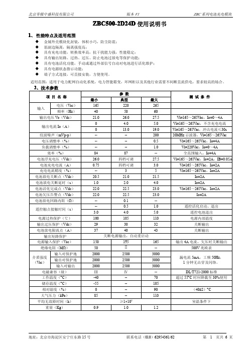
ZBC500-2D24D使用说明书
版本 V1
ZBC 系列电池充电模块
D 使用说明书 ZBC500-2D24 ZBC500-2D24D
1、 性能特点及适用范围
� � � � � � � 金属外壳模块化封装,体积小巧,防尘防震; 原副边隔离,隔离强度高; 具有充电功能,转换效率高,抗干扰能力强,性能稳定; 具有输出短路、过热、过压、防止电池过放电等保护功能; 具有电池活化功能,手动或通过外部信号自动对电池进行活化维护; 具有电源状态指示功能; 端子方式连接,可直接安装,方便使用。
5.2 接线示意图
图4
接线示意图
地址:北京市海淀区安宁庄东路 15 号
联系电话(010)62954361/62
第
3 页共 6 页
北京零极中盛科技有限公司
版本 V1
ZBC 系列电池充电模块
接线说明:K1 K2 K3 为用户 CPU 等控制的继电器触点(也可是光耦,VG 为负,但光耦不应有漏电流) ,R 为电池活化放 电电阻,负载为用户正常负载,电池为 24V 电池组。接线端子容量 300V/15A。
地址:北京市海淀区安宁庄东路 15 号
联系电话(010)62954361/62
第
4 页共 6 页
北京零极中盛科技有限公司
版本 V1
ZBC 系列电池充电模块
告警端子 VC POK HOK VL VH
告警名称 告警输入正端 输入失电告警 活化状态 电池欠压告警 过压或过热告警
正常(或非活化)状态 -通 断 断 断
第
5 页共 6 页
北京零极中盛科技有限公司
版本 V1
ZBC 系列电池充电模块
7、外形及安装尺寸(单位:mm
公差均按 GB/T 1804-2000m 级)
UR75020-AD-H充电模块产品使用说明书201705
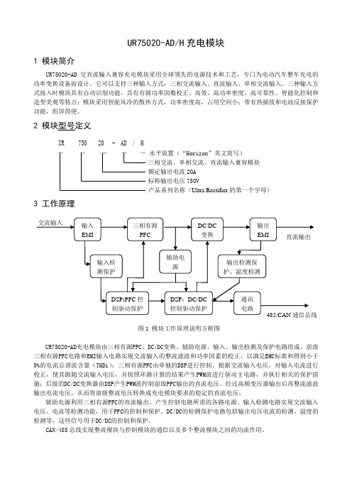
UR75020-AD/H充电模块1 模块简介UR75020-AD交直流输入兼容充电模块采用全球领先的电源技术和工艺,专门为电动汽车整车充电的功率变换设备而设计。
它可以支持三种输入方式:三相交流输入、直流输入、单相交流输入。
三种输入方式接入时模块具有自动识别功能。
具有有源功率因数校正、高效、高功率密度、高可靠性、智能化控制和造型美观等特点;模块采用智能风冷的散热方式,功率密度高,占用空间小;带有热插拔和电池反接保护功能,组屏简便。
2 模块型号定义UR 750 20 - AD / H-----水平放置(“Horizon”英文简写)三相交流、单相交流、直流输入兼容模块额定输出电流20A标称输出电压750V产品系列名称(Ultra Rectifier的第一个字母)3 工作原理图1 模块工作原理说明方框图UR75020-AD充电模块由三相有源PFC、DC/DC变换、辅助电源、输入、输出检测及保护电路组成。
前级三相有源PFC电路和EMI输入电路实现交流输入的整流滤波和功率因素的校正,以满足EMC标准和得到小于5%的电流总谐波含量(THDi);三相有源PFC由单独的DSP进行控制,根据交流输入电压,对输入电流进行校正,使其跟随交流输入电压,并按照环路计算的结果产生PWM波进行驱动主电路,并执行相关的保护措施;后级的DC/DC变换器由DSP产生PWM波控制前级PFC输出的直流电压、经过高频变压器输出后再整流滤波输出电流电压,从而将前级整流电压转换成充电模块要求的稳定的直流电压。
辅助电源利用三相有源PFC的直流输出,产生控制电路所需的各路电源。
输入检测电路实现交流输入电压、电流等检测功能,用于PFC的控制和保护。
DC/DC的检测保护电路包括输出电压电流的检测,温度的检测等,这些信号用于DC/DC的控制和保护。
CAN/485总线实现整流模块与控制模块的通信以及多个整流模块之间的均流作用。
4 性能参数4.1环境条件表1 模块的各种环境条件表三相交流输入模式直流输入、单相交流模式4.2输入特性表 2 模块输入特性表(三相交流输入)电网频率50 Hz±15 Hz输入功率因数≥0.98输入电流总谐波畸变率≤5%效率≥95%(满载效率)开机输入冲击电流≤最大输入电流120%三相交流输入模式直流输入模式单相交流输入模式4.3输出特性表 3 模块输出特性表三相交流、直流输入模式单相交流输入模式4.4 绝缘电阻测试电压500VDC,交流输入端对机壳、对直流输出以及直流输出端对机壳的绝缘电阻>100MΩ。
Mornsun MBP500-2A54D54L 500W AC DC 电池充电模块电源说明书

500W,165-264V AC Input,Dual outputAC/DC battery charging module power supplyRoHSFEATURES●Low stand-by power consumption●Maximum instantaneous power up to 702W●With charging function,the 48V output Lead-acidbattery can be charged,when system connected with battery,it can be used as uninterrupted power supply ●With charge and discharge management,battery status display,battery activation,external communications and control functions●Output over-current,over-voltage protection,batteryreverse polarity protection ●2.5KVAC high isolation voltage●Industrial grade operating temperature:-40℃to +70℃●Chassis mountingMBP500-2A54D54L is AC/DC battery charge power converter offered by Mornsun.It features wide input voltage range,taking both DC and AC input voltage,output over-current,over-voltage,battery reverse polarity protections,strong ability in adapting power grid.This product has power working status display and Intelligent charging function,it can used to charge the 48V lead-acid battery,when AC is power-off,the battery can supply power to the load;it has battery activations and over discharge protection function,the activation maintenance of battery can be done manual or automatic through external signals.Designed specifically for distribution automation terminal (DTU/FTU).It is widely used in the power industry switch substations,power substation,RMU,Intelligent Package Substation,Intelligent Switch Controller and other industries which need uninterrupted power supply.Selection GuidePart No.Output PowerNominal Output Voltage and CurrentMaximum Output PowerEfficiency(220VAC,%)(Vo/Io)(VB/IB)MBP500-2A54D54L135W54V/1A54V/1.5A702W85(Po=135W)Input SpecificationsItemOperating Conditions Min.Typ.Max.Unit Input Voltage Range AC input 165220264VAC DC input200310370VDC Input frequency 405060Hz Input current 220V AC,Typical load -- 2.0--AInrush current 220V AC--60--Hot PlugUnavailableOutput SpecificationsItemOperating ConditionsMin.Typ.Max.Unit Output CurrentInput voltage range,charge current (lB=1.5A)-- 2.510(30S)A13(1S)Output Voltage Accuracy Input voltage range --±2--%Line Regulation Full load --±0.5--Load Regulation 10%-100%load--±1--Ripple &Noise*20MHz bandwidth(peak-to-peak value)----400mV Battery charge current 1.35 1.5 1.65A Battery discharge cut-off point Typical load 414243V Battery activation finished point Typical load 444546Battery under voltage alarm point Typical load444546Battery discharge cut-off delay time --40--s Remote control contact time Remote control activating function on/off --0.5--Remote control battery exit --4--Stand-by Power ConsumptionInput voltage range,Po=14W ----25V A Input voltage range,Po=20W ----40Short Circuit Protection Input voltage range,disconnect the battery Hiccup,Continuous,self-recovery Over-current Protection13----AOver-voltage Protection Input voltage range,do not connect thebattery,When the fault disappears,thepower supply is self-recovery working--60--VBattery Reverse Polarity Protection Battery reverse access Power supply no outputHold-up Time Input voltage range,Po=20W0.50.8--s Note:*Ripple and noise are measured by“parallel cable”method,please see AC-DC Converter Application Notes for specific operationGeneral SpecificationsItem Operating Conditions Min.Typ.Max.UnitIsolation Voltage Input-outputTest time:1min2500----VAC Input-Case2500----output-Case2500----Impulse Voltage Input-outputApply5kV impulse test voltage between input andoutput.Add1.2/50us impact waveform,includingthree positive impulse and three negative impulsewhose time interval is no less than5seconds.Andthere should not have disruptive discharge duringthe test.5000----V Input-Case5000----output-Case5000----Isolation Resistance Input-output Room temperature50----MΩInput-Case Room temperature50----output-Case Room temperature50----Operating Temperature*-40--+70℃Storage Temperature-40--+105Shell Operation temperature*----+80Storage Humidity----95%RH MTBF MIL-HDBK-217F@25℃>100,000hNote:*When the ambient temperature exceeds50℃,it should be taken the cooling method of force air cooling or post cooling to ensure that the module shield temperature is not more than80℃.Physical SpecificationsCasing Material MetalPackage Dimensions168.00*111.20*42.50mmWeight 1.15Kg(Typ.)Cooling method Free air convectionEMC SpecificationsEMS ESD IEC/EN61000-4-2Contact±8KV Perf.Criteria B RS IEC/EN61000-4-330V/m perf.Criteria AEFTIEC/EN61000-4-4Power port±4KV perf.Criteria BIEC/EN61000-4-4Signal port±2KV perf.Criteria B Surge IEC/EN61000-4-5Power port line to line±2KV/line to ground±4KV perf.Criteria B CS IEC/EN61000-4-610Vr.m.s perf.Criteria A PFM IEC/EN61000-4-8100A/m perf.Criteria A Voltage dips,short interruptionsand voltage variations immunityIEC/EN61000-4-110%,70%perf.Criteria BPrinciple block diagramFig1.Internal principle diagram Fig2.Internal isolation diagram Panel description1.Charging and operation indicator light 4.Battery under-voltage indicator light 7.Manual activation quit button2.Battery discharge indicator light5.Battery fault indicator light8.Manual battery input button3.Battery activation indicator light6.Manual activation start button9.Manual battery quit buttonWiring Description 1.Terminal DefinitionTerminal No.TerminalnameDefinition TerminalNo.TerminalnameDefinition TerminalNo.TerminalnameDefinition1ACL AC input L phase9VH Power supplyfault alarm signaloutput terminal17Vo+Load output(+)2PE Protective grounding10HK Remoteactivation startcontact terminal18Vo+Load output(+)3ACN AC input N phase11HG Remoteactivation quitcontact terminal19B+Battery input(+)4NC No electricalconnection12BGRemote batteryquit contactterminal20B+Battery input(+)5VC Power supply for alarmunit(+5v to+24V DC)13RL Power supply foractive dischargeresistor(+)21B-Battery input(-)6POK Input loss alarm signaloutput terminal14VG Remote publiccontact terminal22B-Battery input(-)7HOK Battery Activated statesignal output terminal15Vo-Load output(-)8VL Battery under-voltagealarm signal outputterminal16Vo-Load output(-)2.Wiring diagramWiring Description:K1K2K3are the contact points for the user’s CPU and other control,R is the battery activated discharge resistance, load is the user's normal load,the battery is48V battery pack.Terminal capacity is300V/15A.The specific use please refer to the Using Manual instructionsFUSEManual Instruction1.Power supply status indicatorCharge,lights Green,Battery Charge indication,It lights when the battery is charging and off when the battery is discharging or activated.Discharge,lights Red,Battery Discharge indication,It lights when the battery is discharging or activated.It goes off when the battery is charging or complete discharging.Activate,lights Red,It lights when the battery is activated.If not,it goes off.Under Voltage,lights Red,It lights when the battery or the output converter under-voltage output.If not,it goes off.Fault,lights Red,In the fail case of over-voltage output,over-current,short circuit,It lights after the output is cut-off.If not,it goes off. 2.Button functions and useActivation Start,Press-button,Battery activation manually start.Activation Stop,Press-button,Battery activation manually quit.Battery Start,Press-button,Battery manually put into.Battery Stop,Press-button,Battery manually quit.Activated button,press the activated start-button then the converter will get into the battery activated state,and the discharged and activated indication lights on,and the battery discharge to the load and the discharged resistance.It is able to quit battery activated state when press the activated stop-button.If not,the converter will automatically finish battery activationBattery button,Press the battery start-button when project debugging or firstly connect the battery but no output,then the battery is used to supply power to the load.Now the discharge indication lights.It is able to manually press the battery stop-button5seconds to cut off the battery,or the battery will be automatically cut off after the battery discharge into the under-voltage breakpoint.Hold the battery start-button can urgently force the battery to output for the load when the battery voltage is lower than the under-voltage breakpoint.Note:The function of battery touch-button does not work when AC power.The time of forcing output should not be too long,so as not to damage the battery.e of PowerThe power supply can work when input is AC the alternating current.The power input current to load is powered by power supply, meanwhile charge battery in constant current and voltage.After the battery is charged,power supply to floating charge state automatically,this moment,the power supply float voltage and current to normal self discharge of battery.When AC power down,the battery can also supply power,0switch time.When the battery discharge to under voltage alarm,output battery under voltage signal point,at the same time under voltage indicator lamp light.When the battery discharge is lower than the under-voltage protection,the power shut off load output automatically.If need to shut off battery output in advance,can press the Manual battery quit button of the battery for manual operation in5seconds or remote control the relay controlled by the CPU to make the battery remote pin BG and VG in short circuit(not less than5seconds),then the battery shut off in advance.4.Activation of BatteryWhen the battery is in floating charge state for a long time,the battery should to be activated to avoid battery plate passivation.It can use the relay controlled by the CPU to make the power activation pin HK and VG in short circuit(not less than0.5seconds),then the power into activation state,the battery discharge and supply power to the load.When the battery discharged to the battery activation, the power automatic starting work to supply the load and charge the battery.When need to withdraw from activation halfway,can press the Manual activation quit button to withdraw from activation,or use the relay controlled by the CPU to make the power pin HG and VG in short circuit(not less than0.5seconds),then withdraw from activation in advance.Note:The activation function does not work when the power supply is not connected to the battery or the battery voltage is lower than the battery activation.5.Application of activated discharge terminal RLRefer to the wiring diagram.The terminal is designed to accelerate the discharge of the battery when the battery is activated,please select the discharge resistance according to different battery capacity.When the power supply works normal,the resistance does not work,When the power source is in the activated state,the resistance is connected to the battery discharge.Choice of discharge current (recommended):Discharge current(A)=0.1*battery capacity(AH)-regular load current(A).If the discharge current value is negative,then the discharge resistance can not be added.When the discharge resistance is hot,should be properly cooled down and away from the power module.6.Application of alarm terminalThe alarm output terminal is the electronic node(see the internal diagram),and the+5V to+24V DC voltage is required to be input at the VC terminal.When an alarm occurs,the alarm node is on or off.Alarm node load capacity is0-15mA,and the voltage derating is0.1-3V.This alarm node is not suitable for the load of a large power,The alarm node must be isolated from the power input,output,housing, and protection(see Figure2),and the insulation strength is2500V AC voltage,insulation resistance is50MΩ.Alarm status is as follows:Alarm terminal The alarm Normal(or non-active)Alarm(or activation) VC Positive input alarm----POK Input loss alarm on offHOK Activated state off onVL Battery under voltage alarm off onVH Fault alarm(over-voltage)off one of BatteryThe power supply can be equipped with6-30AH lead acid battery or colloidal maintenance-free battery,The battery is connected to the battery terminal(B+、B-)of the power supply.When the load current is less than20A,the load is connected to the output terminal of the power supply.When the instantaneous load current exceeds20A,the load can be directly connected to the battery,at this time,the power supply of discharge protection function is failure.Charge current selection of the power supply:Generally,The charge current of the battery is selected according to the battery capacity of10%or parameters provided by battery manufacturers.The following table is for reference:battery capacity(AH)10-1515-20charging current(A)1 1.58.Battery anti-reverse connect protection(No battery reverse connection,when there is AC input.)①When there is no AC input and battery reverse connection,press the battery start button,power supply will not have output,and the indicator doesn't light.②When battery is reverse connected,turn on the AC input,the under-voltage will light up.In the above two cases,power supply have no output,but will not be damaged.After correct the battery's connection polarity,the power supply will work normally.Dimensions and Recommended LayoutAttention Matters in Application(1)Output please use wire that cross area is more than2.5mm²,input terminal should add10A/250V AC Fuse.(2)Please correct connection according to the wiring diagram,do not connect wrongly,battery output terminal is strictly prohibited to connect reversely,AC input terminal is strictly prohibited connected with other terminals wrong,otherwise will cause permanent damage to power.(3)The installation method is installed on the vertical direction with terminal down,and identification right.(4)Connecting terminal capacity is15A,the output and the battery terminal is applied to two terminals,otherwise it is easy to burn the connecting terminal.(5)Alarm terminal is prohibited from overload and short-circuit,otherwise it will burn down the electronic alarm contact.(6)To further reduce the output ripple noise,the user can parallel connection with one220-470uF/63V electrolytic capacitor and1uF multilayer Ceramic Capacitor.(7)The output of this product is not allowed to work in parallel.(8)The PE terminal of this product should be reliably connected to the earth,in order to improve the capability of anti-interference.(9)Casing will distribute heat when the power is during operating,in order to ensure the power dissipation is good,please keep a certain gap around the power supply to ensure the air flow smoothly,the temperature sensitive device as far as possible from the power.Note:1.Packing information please refer to Product Packing Information which can be downloaded from .Packing bag number:58220034;2.If the product is not operated within the required load range,the product performance cannot be guaranteed to comply with all parameters in the datasheet;3.Unless otherwise specified,parameters in this datasheet were measured under the conditions of Ta=25℃,humidity<75%with nominal input voltage and rated output load;4.All index testing methods in this datasheet are based on our Company’s corporate standards;5.We can provide product customization service,please contact our technicians directly for specific information;6.Specifications are subject to change without prior notice.Mornsun Guangzhou Science&Technology Co.,Ltd.Address:No.5,Kehui St.1,Kehui Development Center,Science Ave.,Guangzhou Science City,Luogang District,Guangzhou,P.R.China Tel:86-20-38601850-8801Fax:86-20-38601272E-mail:***************。
R100030G1 充电模块用户手册说明书

R100030G1 充电模块用户手册文档版本草稿A发布日期2020-02-17版权所有© 华为技术有限公司2020。
保留一切权利。
非经本公司书面许可,任何单位和个人不得擅自摘抄、复制本文档内容的部分或全部,并不得以任何形式传播。
商标声明和其他华为商标均为华为技术有限公司的商标。
本文档提及的其他所有商标或注册商标,由各自的所有人拥有。
注意您购买的产品、服务或特性等应受华为公司商业合同和条款的约束,本文档中描述的全部或部分产品、服务或特性可能不在您的购买或使用范围之内。
除非合同另有约定,华为公司对本文档内容不做任何明示或默示的声明或保证。
由于产品版本升级或其他原因,本文档内容会不定期进行更新。
除非另有约定,本文档仅作为使用指导,本文档中的所有陈述、信息和建议不构成任何明示或暗示的担保。
华为技术有限公司地址:深圳市龙岗区坂田华为总部办公楼邮编:518129网址:https://修改记录修改记录累积了每次文档更新的说明。
最新版本的文档包含以前所有文档版本的更新内容。
文档版本Draft A (2020-02-17)草稿版本。
手册内容还存在变更,以正式发布版本为准。
用户手册目录目录前言 (ii)1 安全注意事项 (1)2 产品概述 (6)2.1 产品简介 (6)2.2 关键特征 (8)2.3 产品外观 (8)2.4 显示面板 (9)2.4.1 显示面板说明 (9)2.4.2 指示灯说明 (10)2.4.3 数码管显示 (11)2.5 输入和输出端子 (11)2.5.1 输入端子 (11)2.5.2 输出端子 (12)3 运输和储存 (14)4 产品安装 (15)4.1 安装前准备 (15)4.2 安装充电模块 (16)4.3 线缆连接 (18)4.3.1 连接直流输出线缆 (18)4.3.2 连接交流输入线缆 (19)4.4 模块上电和参数设置 (20)5 技术规格 (21)A 缩略语 (24)1 安全注意事项通用安全注意事项●在安装、操作、维护华为公司设备时,请先阅读并遵守本手册的安全注意事项。
英飞源充电模块说明书
英飞源充电模块说明书一、产品概述二、使用方法1.温度条件:在-20℃至60℃的环境温度范围内,可正常使用。
2.输入电压:输入电压范围为AC220V~AC240V,频率为50Hz/60Hz。
3.输出电压:输出电压为DC48V,电流为10A。
请确保被充电设备支持DC48V电压。
4.充电连接:将充电模块的插头插入电动车充电接口,确保连接牢固。
5.开关机操作:将电源插头插入电源插座,将充电模块的开关从OFF转到ON,即可将充电模块开启。
同样的,关闭充电模块时,将开关从ON转到OFF。
6.充电环境:在充电模块启动的同时,请确保周围没有易燃、易爆物品,并保证通风良好。
三、注意事项1.使用前请先阅读本说明书,并按照说明书上的提示进行操作。
2.充电模块仅适用于电动车充电,请勿将其用于其他用途。
3.使用过程中请勿淋湿水或其他液体,以免引发短路和电气故障。
4.在充电时请勿将充电模块接触到裸露的电线或电源插座。
5.在充电时请勿触碰插头和插座,以免引发触电危险。
6.请勿将充电模块与易燃、易爆物品接触在一起,以防火灾和爆炸危险。
7.若长时间不使用充电模块,请及时将其断开电源并存放在干燥、通风的地方。
四、维护保养1.定期清洁:使用过程中,请定期清洁充电模块的外壳,确保散热良好。
2.防尘防潮:若长时间不使用充电模块,请使用防尘罩将其覆盖,以保护内部部件不受灰尘和湿气侵害。
3.定期检查:定期检查充电模块的电源线是否磨损或受损,若有破损,请立即更换,以防电气事故发生。
五、注意事项1.请勿儿童单独使用充电模块,请保持儿童远离充电模块以防触电危险。
2.请遵守国家和地方的充电规定和法规。
4.请勿进行自行维修、改装或拆卸充电模块,以免引发意外事故。
5.若长时间没有充电需求,请将充电模块拔掉电源插头,并存放在干燥、通风的地方。
六、售后服务。
英可瑞20KW充电模块说明书
英可瑞20KW充电模块说明书1.英可瑞20KW充电模块介绍三相交流电源经过EMⅠ滤波器输入到整流电路,将交流整流为脉动的直流输出,通过无源功率因素校正PFC电路,将脉动的直流转换为平直的直流电源,DC/AC高频逆变器将直流转换为高频交流电源,通过高频整流电路将高频的AC转换为高频脉动的直流,此直流通过高频滤波输出。
其中DC/AC高频变换电路在脉宽调制(PWM电路的控制下通过调整变换电路的脉冲宽度,以实现电压调整(包括稳压和电压整定。
整个充电模块在微机系统的监控下工作,包括模块的保护、电压调整等,同时微机实现将充电模块的运行数据上报到监控模块和接受监控模块的控制命令。
2.英可瑞20KW充电模块技术指标充电模块的主要功能是实现AC/DC变换。
充电模块可以在自动监控模块控制和手动/人为控制两种工作方式下工作。
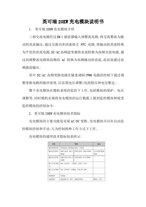
充电模块的通用技术指标如表所示:●充电模块前面板上的高亮度LED数码管指示模块的输出电压或电流,由显示转换开关进行切换。
●面板上的发光二极管分别指示模块输入电源正常(绿色、模块保护(黄色、模块故障(红色。
其中,模块保护包括交流过、欠压,过温、缺相,输出欠压等;模块故障包括模块输出过压。
●模块面板上嵌入的电位器用来调整模块在手动状态下的输出电压,注意只有在手动方式下,调节该电位器才起作用。
●充电模块地址及手动/自动拨码开关用来设置模块通讯地址和选择手动功能,其定义如图所示:●自动/手动工作方式:自动:在自动工作方式下,模块的输出电压、限流点、开关机均由监控模块进行控制,人工无法进行干预,如果模块设计用作合闸模块,对电池进行充电,一般应设置为自动工作方式。
手动:手动状态下,模块的输出电压有上述介绍的面板电位器进行调整,模块的输出电压、限流点和开关机等均不受监控模块控制,但可以将模块的运行参数上报给监控模块。
如果模块连接到控制母线上,为单一稳定电压输出,应将模块设置为手动状态,调整电位器为需要输出的电压值,此时模块的限流点全部放开,为105%~110%。
- 1、下载文档前请自行甄别文档内容的完整性,平台不提供额外的编辑、内容补充、找答案等附加服务。
- 2、"仅部分预览"的文档,不可在线预览部分如存在完整性等问题,可反馈申请退款(可完整预览的文档不适用该条件!)。
- 3、如文档侵犯您的权益,请联系客服反馈,我们会尽快为您处理(人工客服工作时间:9:00-18:30)。
充电模块说明书
通合充电模块
2.1.1 三相输入模块简介
三相输入系列智能型高频开关电源模块,是电力电源最主要的配置
模块,同时也是我公司推出的第三代产品,是专门为电力系统设
计,具有“四遥”功能的高频开关电源,模块采用世界领先的“谐
振电压型双环控制的谐振开关电源”技术,生产出来的模块具有体
积小、重量轻、效率高、空载损耗小、可靠性高等优点。
产品包括
220V和110V两大系列,十多个品种,配有标准RS-485接口,易于
与自动化系统对接,适用于各种容量的直流系统。
型号说明
TH 系列号 3:代表第三代产品
ZZ:自冷智能型模块;NZ:风冷
额定输出电流值:5A、7A、10A、
模块类别:D代表电
直流额定输出电压等级
230为标称电压220V
TH 为“通合电
产品系列三相输入充电模块产品主要型号如表2-1所示。
表2-1 三相输入充电模块产品型号
2.1.2 模块主要特点
●采用全程软开关技术,效率高,空载功耗小,体积小。
●交流输入内置符合安规的保险管。
●直流输出内置二极管,能够不增加额外措施实现热插拔。
同类其
它没有内置二极管的产品,用户需要额外在直流屏上增加二极管
散热片,接线繁琐。
●采用“三相无源功率因数校正电路”,输入无中线,功率因数可
达0.94。
●采用隔离自主均流,并机不均流度<±3%,可保证二十台以上模
块良好并机。
●模块具有RS-485接口,方便接入自动化系统进行通信。
●输出过压保护:内置过压保护电路,出现过压后模块自动锁死,
模块故障指示灯亮,故障模块自动退出工作,不影响整个系统正
常运行;过压保护点:220V模块为320V±5% ,110V模块为
160V±5% 。
●输出限流保护:每个模块输出电流最大限制为额定输出电流的
1.05倍。
●短路保护:采用回缩下垂限流方式,模块电流输出特性如图2-1,
输出短路时模块在瞬间把输出电压拉低到零,限制短路电流在额
定输出电流的15%以下。
模块可长期工作在短路状态,不会损
坏,排除故障后模块可自动恢复工作。
图2-1 整流模块输出
●模块并联保护:模块内部有并联保护电路,故障时模块自动退出
系统,不影响其它模块正常工作。
●过温保护:模块检测散热器温度超过85℃左右时自动关机保护,
温度降低后模块自动启动。
2.1.3 技术指标三相输入充电模块特点及技术参数如表2-2、表2-3所示。
表2-2 220V系列模块特点及技术参数
表2-3 110V系列模块特点及技术参数。
