学生套件2(万能充)
NEKLO安全套件Magento2用户指南说明书

Security Suite for Magento 2User GuideIntroductionWelcome to the User Guide for NEKLO Security Extension. Thank you for choosing our product.This User Guide describes the functionality of the Security Extension made by NEKLO and explains how to use it. Enjoy.Neklo Security is an extension for Magento 2 that makes your online store secured and protected from unauthorized admin users, malware, and hack attacks. The extension grants you a range of options to take the security of your online store to the new level.The extension is a combination of the best proven solutions, created to make your Magento 2 website a safe place for buying. Two-factor authentication, advanced password verification procedure, the Lock User function, and Scanner will give you a total control over your store 24/7.Decide, who may access your store as an admin, and stay in the know. Detect login attempts, monitor actions made by admin users, and get email notifications of Magento Admin Activities. With the Security extension for Magento 2 you will get a full picture of what is happening in your store.Installation1. Install library using console command: composer require authy/php:^3.02. Unpack the zip file provided into the root folder of your Magento 2 installation.3. From a command line runbin/magento module:enable Neklo_Corebin/magento module:enable Neklo_Securitybin/magento setup:upgradebin/magento setup:static-content:deployMagento Compatibility:Community Edition 2.1.x - 2.2.xEnterprise Edition 2.1.x - 2.2.xIf you experience any issues with the installation, please contact us.Configuration - How to enable Security SuiteTo enable Security Suite for your store, you need to complete the following steps:1. Log into your Magento Admin Panel.2. Go to Stores > Settings > Configuration > Neklo tab > Security Suite > General Settings3. “In Enabled” should be “Yes”.4. Click “Save Config” to apply the changes.Advanced User ValidationAdvanced Password Validation Settings allow you to set advanced password requirements for your users to reduce the possibility of password phishing.1. To view Advanced Password Validation Settings, go to Stores > Settings > Configuration >Neklo tab > Security Suite > Advanced Password Validation Settings tab.2. To unfold the list of password requirements, choose “Yes” in the “Use advanced passwordrequirements” field.3. The advanced settings include “Minimum Password Length”, “Use both lower and upper-caseletters”, and “Use special chars” fields. It is recommended to set all these options to “yes” to increase the security of your password policy to maximum. Minimum password length should not be less than 7 characters.Password Lifetime SettingsPassword Lifetime Settings allow to configure various time restrictions for the users’ passwords. 1. To view Password Lifetime Settings, go to Stores > Settings > Configuration > Neklo tab >Security Suite > Password Lifetime Settings.2. In order to use the Security Suite Password Lifetime Settings, you should clear a tick box on theright of the fields you want to use.Password lifetime restrictions include the following:1. ”Password Lifetime (days)” allows to choose how many days the passwords will be used. It isrecommended to set the Password Lifetime to no more than 90 days. Upon expiration of this time period, the user will be notified to change their password in Admin Panel.2. ”Password Lifetime (successful logins)” allows to set the number of logins before the passwordshould be changed. For example, after 30 successful logins the user will not be able to login with the old password.3. “Password change” notifies the user about the Password Lifetime is running short. If“Recommended”, a small window will appear on the top of the page telling it is time to change the password. If “Forced”, then the system will force the user to change the password by constantly redirecting him to the Account Settings page.4. Maximum Login Failures to Lockout Account regulates the number of maximum login attemptsbefore blocking the user. After the successful login, the number of previous login failures isaccumulated for the rest of the password lifetime.5. Lockout Mode allows to set whether the user blocking will be temporary or permanent. InLock Time (minutes) you can set up the period in minutes. Account will be unlocked after Lock Time (minutes) expires. Permanent mode locks user permanently until the account is manually unblocked.Please note that you can lock any user automatically. Security Suite provides Lock User functionality similar to the default Active/Inactive functionality. Locked users will be unable to login into your Magento instance. To lock user manually, go to System > Permissions > All Users and choose the user you want to lock.Twillio SettingsBefore enabling 2FA, you need to create and configure an account on .Please note that NEKLO is not currently associated with Twillio, so this service may charge fees for its functionality. If you have any issue with your Twillio account, please contact them through their support website or at *******************.To connect your Twillio account to your Magento store, complete the following steps:1. Log in into your Twilio account and go to Authy section.2. Create new application by following the directions3. Go to Authy > Name > Settings and configure the settings according to your preferences. Theseare the recommended settings are for the smooth work of Security Suite extension: Authentication via SMS - Enabled.• Force SMS - DISABLED (please use this configuration only in case if «Sync tokens in Authy app» is enabled)• Force Phone Calls - DISABLED.• Sync tokens in Authy app - Enabled.4. After the settings are configured, you can copy your production API Key at the top of the page.You will need in further Security extension configuration.Two-Factor authentication (2FA)This set of settings allows you to choose how 2FA will be performed in your Magento store.1. To view Two-factor authentication (2FA) Settings, go to Stores > Settings > Configuration >Neklo tab > Security Suite > Two-factor authentication (2FA).2. To unfold the list of advanced settings, choose “Yes” in the “Is Enabled” field.There are several work modes for the 2FA to choose from in:1. IP Whitelist. This setting is needed to enable admin access only for specific IP addresses. If thesetting is enabled, it is necessary to add admin IP addresses in the “Allowed IP list” field. If no IP addresses will be added, no admin user will be able to login into admin panel.• “Allowed IP list” is the field where you need to add appropriate IP addresses with the “Add”button.• Click “Save Config” to apply the changes.2. SMS Code . If enabled, this mode allows sending codes for authentication to the mobile numbers stated in the User General Settings. It is necessary to complete the following steps for SMS Code to work:• insert Twilio API key into the “Authy API key ” field to connect your Magento store with the specific Twilio account.• add phone number for at list one Magento admin user in System > Permission > All Users > The user you want .• Click “Save Config ” to apply the changes.Please note that 2FA will be enabled only after at least one admin user will verify his mobile phone number with Twilio. Verification instructions are described below.IMPORTANT NOTE: before enabling 2FA please enter your IP address in Allowed IP List. If you do not do this but enable 2FA, after a logout you will not be able to login in Magento.3. Both (SMS code with IP Whitelist). This mode requires the user to complete both 2FA steps. Theuser’s IP should be listed in the IP Whitelist, and if this is so, the user should complete SMS code verification.4. Combined (SMS code or IP Whitelist). In this mode, if you log in into Magento admin not fromwhitelisted IP, you will be redirected to the Confirmation page. There you need to enter the security code from the SMS. Please note that the SMS verification will work only if the user has verified his mobile phone number with Twilio.Twilio Verification process1. Make sure you have entered a valid API Key from your Twillio account and added yourIP in the allowed list.2. Proceed to System > Permission > All Users. If 2FA feature has been enabled, therewill be a new required field, which is “Phone Number”.3. Phone Numbers must be inputted for every user. If a user does not have a phonenumber assigned and this user’s IP is not in the Allowed IP List, he will not be able tolog in as an admin.must be confirmed.5. You will get a text message with theverification code to the particular phonenumber.6. Once you enter a verification code andsave the user, you will see a message that the phone number has been verified.For all users that have been setup with 2FA upon thevalid login with their username and password, theywill receive a verification code on their mobile devicein SMS or via Twilio Authy application during Magentoadmin login.The system will require a second prompt for SecurityCode. Only upon entering the Security Code the userwill be allowed to login into the Magento instance.You should enter this security code on the login pageand click on the Confirm button.And now your account should be successfully logged in Magento Admin. ScannerThis feature will schedule an automatic scan of your Magento Instance by www.magereport. com. All results of scanning will be listed in Magento Admin Panel. You may manually rescan your store any time.To view Scanner settings, go to Stores > Settings > Configuration > Neklo tab > Security Suite > Scanner.To enable MageReport automatic scanning, choose “Yes” in the “Is Enabled by Cron” field. if enabled, the scan is executed once per day at midnight of the server’s local time by cron. Rescan button allows you to run Magereport check immediately.Notification SettingsNotification settings allow you to select specific Magento activities that will be notified to you via email.1. To view Scanner settings, go to Stores > Settings > Configuration >Neklo tab > Security Suite > Notification Settings.2. To enable email notifications, choose “Yes” in the “Is Enabled” field.3. In Sender field, you can specify the email sender. Sender emails are taken from Stores >Settings > Configuration > General > Store Email Addresses.4. In the “Event List” field, you can select what admin user activities you want to be notified about.5. In the “Recipients” field, you can add and delete the users who will get email notifications.6. Click “Save Config” to apply the changes.Here is an examplу of how the email notification from Security Suite looks like.Logger SettingsNeklo Security Suite extension starts the logging process immediately after it was installed. So after all the installation instructions are done, the extension starts collecting admin activity logs. This info is stored in separate database tables and can be viewed and managed in Login Attempts and Action Logger grids.To view Logger Settings, go to Stores > Settings > Configuration > General > Logger Settings. These settings include the following:1. Action logger lifetime (Days). You can manage for how long the logs will be stored on yourserver and in Login Attempts grid in days. The data will be removed from the database once the specified number of days has passed.2. Login Attempts Lifetime (Days). Here you can choose for how long the Login info willbe stored on your server and in Account Logger grid. The data will be removed from the database once the specified number of days has passed.3. Is Export Enabled. This setting allows to export file automatically before the data will beremoved from server. Files are stored under var/export folder.4. Click “Save Config” to apply the changes.Since potentially there could be a larger amount of data recorded, Security Suite extension provides log truncation rules which will give you an ability to delete data older than Lifetime fields specify. Logs are stored on the server under var/export folder.Login Attempts GridLogin Attempts grid reflects all login attempts and extensive information about them. Login Attempts grid is located under System > Security Suite > Login Attempts.Action Logger GridAction Logger shows all the actions made by admin users. Action Logger grid is located under System > Security Suite > Action Logger.Admin Sessions GridSessions grid displays all the admin sessions both active and ended. Here you can terminate any active session you find suspicious.You can find the grid following My Account > Account Settings and then scroll down. There you will see a table with all the admin sessions.SupportThank you for using this extension. You will find more our great solutions for Magento here: 。
(完整word版)电子制作课程项目手机电池简易万能充电器
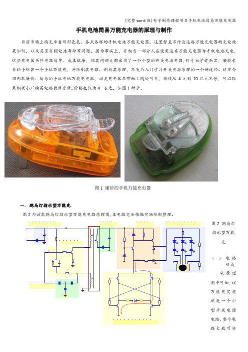
手机电池简易万能充电器的原理与制作目前市场上面充斥着形形色色、各式各样的手机电池万能充电器,这里暂且不讨论这些万能充电器的充电效果如何,以及是否有损电池寿命等问题,因为事实上,有相当一部分人在使用这类万能充电器为手机电池充电.这些充电器虽然电路简单、成本低廉,但其内部大都采用了一个小型的开关电源电路,对于初学者而言,若能亲自动手组装一个手机万能充,并绘制其电路、剖析其原理,不失为入门学习开关电源原理的一个好途径。
这里介绍两款廉价、简易的手机电池万能充电器,该类充电器在市面上随处可见,价钱从4元到10几元不等,可以联系相关小厂购买电路散件套件,价格也仅为4—6元,如图1所示。
一. 跑马灯指示型万能充图2为该款跑马灯指示型万能充电路原理图,本电路完全根据实物绘制整理。
图2 跑马灯指示型万能充(一) 电路组成 从原理图中可知,该万能充实质就是一个小型开关电源电路,整个电路大致可分图1 廉价的手机万能充电器为以下几个部分:输入整流滤波电路、开关振荡电路、过压保护电路、次级整流滤波电路、稳压输出电路、自动识别极性及充电电路、跑马灯充电指示电路等。
(二)电路基本工作原理当充电器插到交流电源上后,220V交流电压经D1半波整流、C1滤波,得到约300V左右的直流电压。
由 Q1、T1、R1、R3、R4、R5、C2等元件组成的开关振荡电路将直流转换为高频交流,振荡过程如下:通电瞬间,+300V电压通过启动电阻R1为开关管Q1提供从无到有增大的基极电流I B,Q1集电极也随之产生从无到有增大的集电极电流I C,该电流流经开关变压器T1的1—2绕组,产生上正下负的自感应电动势,同时在T1的正反馈绕组3-4中也感应出上正下负的互感电动势,该电动势经R3、C2等反馈到Q1的基极,使I B进一步增大,这是一个强烈的正反馈过程:I I B↑在这个正反馈的作用下,Q1迅速进入饱和状态,变压器T1储存磁场能量。
此后正反馈绕组不断的对电容C2充电,极性为上负下正,从而使Q1基极电压不断下降,最后使Q1退出饱和状态,T1 1—2绕组的电流呈减小趋势,T1各绕组的感应电动势全部翻转,此时T1 3—4绕组的感应电动势极性为上负下正,该电动势反馈到Q1的基极后,使IB进一步减小,如此循环,进入另一个强烈正反馈过程,使Q1迅速截止.随后C2在自身放电及+300V对它的反向充电的作用下,又使Q1基极电压回升,进入下一轮循环,从而产生周期性的振荡,使Q1工作在不断的开、关状态下。
ServeRAID M5100 系列电池套件快速安装指南说明书
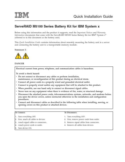
Quick Installation Guide ServeRAID M5100Series Battery Kit for IBM System xBefore using this information and the product it supports,read the Important Notices and Warranty Information documents that come with the ServeRAID M5100Series Battery Kit for IBM®System x®(referred to in this document as the battery unit).This Quick Installation Guide contains information about remotely mounting the battery unit in a server and connecting the battery unit to a transportable memory module.Statement1:DANGERElectrical current from power,telephone,and communication cables is hazardous.To avoid a shock hazard:v Do not connect or disconnect any cables or perform installation,maintenance,or reconfiguration of this product during an electrical storm.v Connect all power cords to a properly wired and grounded electrical outlet.v Connect to properly wired outlets any equipment that will be attached to this product.v When possible,use one hand only to connect or disconnect signal cables.v Never turn on any equipment when there is evidence of fire,water,or structural damage.v Disconnect the attached power cords,telecommunications systems,networks,and modems before you open the device covers,unless instructed otherwise in the installation and configurationprocedures.v Connect and disconnect cables as described in the following table when installing,moving,or opening covers on this product or attached devices.To Connect:To Disconnect:1.Turn everything OFF.2.First,attach all cables to devices.3.Attach signal cables to connectors.4.Attach power cords to outlet.5.Turn device ON.1.Turn everything OFF.2.First,remove power cords from outlet.3.Remove signal cables from connectors.4.Remove all cables from devices.Statement28:CAUTION:The battery is a lithium ion battery.To avoid possible explosion,do not burn the battery.Exchange it only with the IBM-approved part.Recycle or discard the battery as instructed by local regulations.In the United States,IBM has a process for collection of this battery.For information,call 1-800-426-4333.Have the IBM part number for the battery unit available when you call.Attention:The battery in the ServeRAID M5100series battery assembly must charge for at least six hours under normal operating conditions.To protect your data,the ServeRAID controller firmwarechanges the write policy to write-through until the battery unit is sufficiently charged.When the battery unit is charged,the ServeRAID controller firmware changes the write policy to write-back to take advantage of the performance benefits of data caching.The battery unit is an intelligent battery backup unit (iBBU)based on lithium ion (LiON)battery cell technology.The battery unit protects the integrity of the cached data on a ServeRAID M5100series controller for up to 48hours (depending on the derated retention time that is selected)in case of a complete ac power failure or a brief power outage.The battery unit is mounted inside a server and is connected by a 20-pin cable to a ServeRAID M5100Series 512MB Cache/RAID 5Upgrade for IBM System x (referred to in this document as thetransportable memory module).Option kit partsThe battery unit option kit contains the following parts:v One ServeRAID M5100Series Battery Kit for IBM System x0Li IonModel:BAT1S1P-A Front ViewRear Viewv Two remote-mount cables –One 50cm (19.7in.)20-pin remote-mount cable–One 95cm (37.4in.)20-pin remote-mount cable2v IBM ServeRAID M Documentation CDv IBM Warranty Information documentv IBM Important Notices documentHandling electronic devicesAttention:Static electricity can damage the server and other electronic devices.To avoid damage,keep an electronic device in its static-protective package until you are ready to install it.To reduce the possibility of damage from electrostatic discharge,observe the following precautions:v Limit your movement.Movement can cause static electricity to build up around you.v The use of a grounding system is recommended but is not required.For example,wear an electrostatic-discharge wrist strap,if one is available.v Handle the device carefully,holding it by its edges or its frame.v Do not touch solder joints,pins,or exposed circuitry.v Do not leave the device where others can handle and damage it.v While the device is still in its static-protective package,touch it to an unpainted metal part of the server for at least2seconds.This drains static electricity from the package and from your body.v If it is necessary to set down the device after you remove it from its static-protective package,put it back into the package.Do not place the device on the server cover or on a metal surface.v Take additional care when you handle the device during cold weather.Heating reduces indoor humidity and increases static electricity.Mounting the battery unit inside the serverAttention:To avoid the loss of data,back up your data before you change your system configuration.To mount the battery unit inside the server,complete the following steps:1.Read the safety information that comes with the server.2.Turn off the server and peripheral devices and disconnect the power cords.Remove the server cover.For more information,see the installation instructions that come with the server.3.In a static-free environment,carefully remove the battery unit from the antistatic bag and inspect it fordamage.If it appears to be damaged,contact your place of purchase.34.Mount the battery unit in a suitable location inside the server,observing the following guidelines:v There is no standard method for mounting the battery unit inside the server.The correct mounting location and procedure depends on the server configuration.v You must connect a remote-mount cable to the battery unit that is installed remotely in the server and to the transportable memory module that is mounted on the controller.Make sure that one of the remote-mount cables that come with the battery unit is long enough to make this connection when the controller is installed in the server.Notes:a.The following illustration shows the controller installed in a PCI Express slot in the server.Yourserver configuration might be different.b.For more information about mounting the battery unit in the server,see the documentation thatcomes with the server.(installed remotely in00L i I o n000Figure 1.Mounting the battery unit in the server4Connecting the battery unit to the transportable memory module on the controllerIf the controller to which you are connecting the battery module is installed in thesever,use thefollowing procedure to first remove the controller from the server.Otherwise,go to“Connecting the battery unit and reinstalling the controller in the server”on page6.Removing the controller from the serverTo remove the controller from the server,complete the following steps:1.Read the safety information that comes with the controller.2.If you have not already done so,turn off the server and peripheral devices and disconnect the powercords.Remove the server cover.For more information,see the installation instructions that come with the server.3.Ground yourself before you touch the controller.4.Disconnect all cables from the controller,remove the screw that attaches the bracket to the server,andcarefully remove the controller from the slot.Notes:a.The following illustration shows the controller installed in a PCI Express slot in the server.Yourserver configuration might be different.b.For more information about removing the controller from the server,see the documentation thatcomes with the server.5.Place the controller on a flat,clean,static-protective surface,and continue with the next section.Figure2.Removing the controller from the server5Connecting the battery unit and reinstalling the controller in the server To connect the battery unit and reinstall the controller in the server,complete the following steps:1.With the controller on a flat,clean,static-protective surface,ground yourself and make sure that the server is grounded.2.Make sure that the ServeRAID M5100Series 512MB Cache/RAID 5Upgrade for IBM System x (transportable memory module)is mounted on the controller.For the mounting instructions,see the Quick Installation Guide that comes with the transportable memory module.3.Connect the battery unit to the transportable memory module:a.Select one of the 20-pin remote-mount cables that come with the battery unit,making sure that it has the correct length for your configuration.The battery unit comes with a 50cm (19.7in.)remote-mount cable and a 95cm (37.4in.)remote-mount cable.b.Connect one end of the 20-pin cable to the battery unit (remotely mounted in the server)and the other end of the cable to the 20-pin cable connector on the transportable memory module that is mounted on the controller.Attention:If you have to remove the controller after the battery unit is connected to it,you must disconnect the remote-mount cable from the transportable memory module on the controller and then remove the controller from the server.Notes:1)The following illustration shows the controller installed in a PCI Express slot in the server.Your server configuration might be different.2)For more information about installing the controller in the server,see the documentation that comes with the server.00L i I o n0000Figure 3.Connecting the battery unit to the transportable memory module and installing the controller in the server 64.Position the controller by aligning the PCIe x8connector with the PCIe x8slot on the system board.Insert the controller firmly into the connector and press down on the top edge of the controller so that it is firmly seated in the connector.See the previous illustration for the correct place to press on the controller.Note:Do not apply pressure to the transportable memory module when you insert the controller.Instead,press down only on the top edge of the controller.5.Replace the expansion-slot bracket screw if you removed it.6.Reconnect the controller to the SAS and SATA devices in the server.7.Replace the server cover,reconnect the power cords,and turn on the server.Replaceable componentsField replaceable units(FRUs)must be replaced only by a trained service technician,unless they are classified as customer replaceable units(CRUs).Tier1CRU:Replacement of Tier1CRUs is your responsibility.If IBM installs a Tier1CRU at your request without a service contract,you will be charged for the installation.Tier2CRU:You may install a Tier2CRU yourself or request IBM to install it,at no additional charge, under the type of warranty service that is designated for your product.For more information about the terms of the warranty and getting service and assistance,see the Warranty Information document that comes with the controller.Table1.Field replaceable units for the ServeRAID M5100Series Battery Kit for IBM System xDescription CRU part number(Tier1)CRU part number(Tier2)FRU part number(trained service technicianonly)ServeRAID M5100Series Battery Kit forIBM System x81Y4491Remote-mount cables for ServeRAIDM5100Series Battery Kit for IBM System x(2cables)90Y73097Getting help and technical assistanceIf you need help,service,or technical assistance or just want more information about IBM products,you will find a wide variety of sources available from IBM to assist e this information to obtain additional information about IBM and IBM products,determine what to do if you experience a problem with your IBM system or optional device,and determine whom to call for service,if it is necessary. Before you callBefore you call,make sure that you have taken these steps to try to solve the problem yourself:v Check all cables to make sure that they are connected.v Check the power switches to make sure that the system and any optional devices are turned on.v Check for updated firmware and operating-system device drivers for your IBM product.The IBM Warranty terms and conditions state that you,the owner of the IBM product,are responsible for maintaining and updating all software and firmware for the product(unless it is covered by an additional maintenance contract).Your IBM service technician will request that you upgrade your software and firmware if the problem has a documented solution within a software upgrade.v If you have installed new hardware or software in your environment,check / systems/info/x86servers/serverproven/compat/us/to make sure that the hardware and software is supported by your IBM product.v Go to /supportportal/to check for information to help you solve the problem.v Gather the following information to provide to IBM Support.This data will help IBM Support quickly provide a solution to your problem and ensure that you receive the level of service for which you might have contracted.–Hardware and Software Maintenance agreement contract numbers,if applicable–Machine type number(IBM4-digit machine identifier)–Model number–Serial number–Current system UEFI and firmware levels–Other pertinent information such as error messages and logsv Go to /support/entry/portal/Open_service_request/to submit an Electronic Service Request.Submitting an Electronic Service Request will start the process of determining a solution to your problem by making the pertinent information available to IBM Support quickly and efficiently.IBM service technicians can start working on your solution as soon as you have completed and submitted an Electronic Service Request.You can solve many problems without outside assistance by following the troubleshooting procedures that IBM provides in the online help or in the documentation that is provided with your IBM product. The documentation that comes with IBM systems also describes the diagnostic tests that you can perform. Most systems,operating systems,and programs come with documentation that contains troubleshooting procedures and explanations of error messages and error codes.If you suspect a software problem,see the documentation for the operating system or program.Using the documentationInformation about your IBM system and preinstalled software,if any,or optional device is available in the documentation that comes with the product.That documentation can include printed documents, online documents,readme files,and help files.See the troubleshooting information in your system documentation for instructions for using the diagnostic programs.The troubleshooting information or the diagnostic programs might tell you that you need additional or updated device drivers or other software. IBM maintains pages on the World Wide Web where you can get the latest technical information and download device drivers and updates.To access these pages,go to /supportportal/. Also,some documents are available through the IBM Publications Center at /shop/ publications/order/.8Getting help and information from the World Wide WebOn the World Wide Web,up-to-date information about IBM systems,optional devices,services,and support is available at /supportportal/.The address for IBM System x information is /systems/x/.The address for IBM BladeCenter®information is/systems/bladecenter/.The address for IBM IntelliStation®information is/systems/intellistation/.How to send Dynamic System Analysis data to IBMUse the IBM Enhanced Customer Data Repository to send diagnostic data to IBM.Before you send diagnostic data to IBM,read the terms of use at /de/support/ecurep/terms.html. You can use any of the following methods to send diagnostic data to IBM:v Standard upload:/de/support/ecurep/send_http.htmlv Standard upload with the system serial number:/app/upload_hwv Secure upload:/de/support/ecurep/send_http.html#securev Secure upload with the system serial number:https:///app/upload_hwCreating a personalized support web pageAt /support/mynotifications/,you can create a personalized support web page by identifying IBM products that are of interest to you.From this personalized page,you can subscribe to weekly email notifications about new technical documents,search for information and downloads,and access various administrative services.Software service and supportThrough IBM Support Line,you can get telephone assistance,for a fee,with usage,configuration,and software problems with your IBM products.For information about which products are supported by Support Line in your country or region,see /services/supline/products/.For more information about Support Line and other IBM services,see /services/,or see /planetwide/for support telephone numbers.In the U.S.and Canada,call1-800-IBM-SERV(1-800-426-7378).Hardware service and supportYou can receive hardware service through your IBM reseller or IBM Services.To locate a reseller authorized by IBM to provide warranty service,go to /partnerworld/and click Find Business Partners on the right side of the page.For IBM support telephone numbers,see/planetwide/.In the U.S.and Canada,call1-800-IBM-SERV(1-800-426-7378).In the U.S.and Canada,hardware service and support is available24hours a day,7days a week.In the U.K.,these services are available Monday through Friday,from9a.m.to6p.m.9IBM Taiwan product serviceIBM Taiwan product service contact information: IBM Taiwan Corporation3F,No7,Song Ren Rd.Taipei,TaiwanTelephone:0800-016-8881011First Edition(March2012)IBM,the IBM logo,and System x are trademarks of International Business Machines Corp.,registered in many jurisdictions worldwide.Printed in USA©Copyright IBM Corporation2012.US Government Users Restricted Rights–Use,duplication or disclosure restricted by GSA ADP Schedule Contract with IBM Corp.(1P)P/N:81Y1389。
Fluke FEV100 电动汽车充电站适配器套件说明书

Fluke FEV100 Adapter Kit for Electric Vehicle Charging StationsVEHICLE SIMULATIONCP Control Pilot state simulation tests different charging statesGROUNDING PROTECTIONPE Pre-Test for dangerous voltageGFCI TESTINGStay protected from and check risk of electric shockCOMPATIBILITYIntegrates into Fluke portfolio of test and measurement toolsSAE J1772Complies with North American standardsTest the functionality and safety of electrical vehicle charging stations, easily and reliablyTest the safety and performance of type 1, level 1 or level 2 elec-tric vehicle ac charging stations (EVSEs) with the Fluke FEV100. This test adapter simulates the presence of an electrical vehicle, allowing you to conduct tests in combination with appropriate test instruments such as a digital multimeter or oscilloscope. Use the FEV100 to verify an EVSE is working properly after install and during periodic maintenance, or troubleshoot an EVSE if it is not delivering the appropriate charge.SafetyEVSE charging cables may become damaged over the course of use, increasing electric shock risks to users. Stay protected from and check risk of electric shock with the GFCI trip test. This function verifies the breaker of the EVSE is connected by detecting ground faults. Additionally, the PE grounding protection pre-test veri-fies that there is no presence of dangerous voltage at the ground terminal.Simplicity and conveniencePerform a variety of tests including ground fault checks, insula-tion of wires, measuring voltage and duty cycle to see max current available for charging all with one adapter that safely integrates with the Fluke portfolio of test and measurement tools. There is no need to bring an electric vehicle onsite for EVSE troubleshooting: the adapter acts as an electric vehicle when connected to an EVSE for easy performance and maintenance testing.How to test a charging stationOnce an EVSE recognizes it is connected to a “car” and is ready for charging, the adapter tests if the EVSE is performing the way it should be. 1. Perform the safety grounding protection pre-test to verify that no dangerous voltage is present in the grounding circuit. If the indica-tor lights up, it is possible that the electrical wiring has been set up improperly or there is a grounding malfunction. In this instance stop further testing immediately and check for a possible wiring fault of the ground conductor. 2. Verify station output voltage using an additional meter, such as the 87V digital multimeter.3. Verify station maximum preset charge current using CP terminals and a meter with a duty cycle function or an oscilloscope.4. Simulate the error states as described in the SAE J1772 standard: CP error “E”, GFCI trip test, and grounding error.CP error “E” simulationThe standard SAE J1772 defines Error “E” as a state when charging station is: disconnected from vehicle, disconnected from utility, there is a loss of utility power or control pilot is short to control pilot reference (ground). This error simulation tests the station to ensure that if there is an issue with the CP of the vehicle, the station and utility will not supply a charge to the vehicle.GFCIEach EVSE is required to be equipped with GFCI protection. On many stations, the GFCI protection is fully automatic and does not need a manual reset after the GFCI circuit is tripped.Ground Error (Ground Fault) simulationThe Ground Error button simulates an interruption of the ground conductor. As a result, the pending charging process is aborted and new charging processes are prevented.Advanced tests such as insulation resistance, power quality, analysis of the control pilot wave-form and loop impedance can also be done using the adapter in conjunction with appropriate test and measurement equipment.Verifying charging voltage with vehicle simulationThe CP state rotary switch selector simulates various vehicle states when the test adapter is connected to the charging station. Vehicle states are simulated with different resistances con-nected between CP and PE conductors.Ordering informationFluke FEV100 Adapter Kit for Electric Vehicle Charging StationsIncluded• Fluke FEV100/BASIC Test Adapter• Fluke FEV-CON/TY1 Type 1 Connector & Cable • Soft Carrying Case • User Manual • 3-year warrantyVisit to get complete details on these products or ask your local Fluke sales representative.The FEV100 is compatible with the Fluke portfolio of test and measurement tools. Take critical measurements such as voltage, waveform, loop impedance and resistance.Recommended tools for use with the FEV100• 87V Industrial Multimeter• 376 FC True-RMS Clamp Meter with iFlex • 1587 FC Insulation Multimeter• 1738 Three-Phase Power Quality Logger • 1630-2 FC Earth Ground Clamp • BT521 Advanced Battery Analyzer• 1664 FC Installation Multifunction Testers• 125B Industrial ScopeMeter® Handheld OscilloscopeFluke CorporationPO Box 9090, Everett, WA 98206 U.S.A.Fluke Europe B.V.PO Box 1186, 5602 BD Eindhoven, The NetherlandsFor more information call:In the U.S.A. (800) 443-5853 or Fax (425) 446-5116In Europe/M-East/Africa +31 (0) 40 2675 200 or Fax +31 (0) 40 2675 222In Canada (800)-36-FLUKE or Fax (905) 890-6866From other countries +1 (425) 446-5500 or Fax +1 (425) 446-5116Web access: ©2021 Fluke Corporation.Specifications subject to change without notice. Printed in U.S.A. 11/2021 211051-210646-en Modification of this document is not permitted without written permission from Fluke Corporation.Fluke. Keeping your world up and running.®。
N5230使用手册
,是指在功能表,应用程序中那些在“整理”状态下,有“删除”选项的。
我基本上都删了(当然,我删之前还是有选择性的运行了几个)。
新手刚上来,不要直接进入“程序管理→已安装的程序”中去卸载软件,等熟悉了以后再说。
刚买来的机子,在功能表的“整理”状态下,比较好判断,凡是重要的、必不可少的手机程序,都是固化在ROM中的,整理状态下是没有“删除”这一项的。
其他的,都可以删……不过要注意哦,像OVI商店这类的,虽然是Nokia捆绑在新版系统中的,却也是可以删的(我还真想删,因为这个破“商店”竟然有好几个程序组成,一装装一堆,还占C盘)。
删的理由很简单,里面有不少(如网秦的几个)是有收费陷井的,一不小心就中招,其他不收费的却又不怎么实用,游戏也不太好玩,留着也是占空间。
有些东东还需要安装,装了不久又要卸载,浪费感情!还是直接全删了省事。
至于OVI商店,好歹也是新功能,留用查看吧……据说,删了会出一点小问题,好象是OVI图标删不掉,所以还是不删为好(这一点不能肯定)。
第二件事:申请证书并学会签名由于有过几年使用PPC手机的经验,所以购机以后的第一件事,就是上网找免费的软件。
我遇到的第一个难题,就是签名和证书,这是PPC的WM系统上没有的东东。
好在网上这方面的教程比较多,看了一下就明白了。
对于新手朋友来说,最需要了解的,就是如何申请证书,如何签名。
当然啦,如果你把手机系统XX了,就不用再为软件签名而烦恼了,但是安装XX助手,还是需要证书的。
所以,不管怎样,你都得申请证书。
我就再把话说白一点吧……证书必须和IMEI串号挂勾的(什么是串号?串号就是手机的“身份证号”,具体自己百度吧),必须用你手机的串号去申请。
别指望别人能EMAIL一个证书给你,都不知道你的串号,哪来的证书。
拿别人的证书,是没有用的。
XX手机还是得申请证书哦。
第三件事:下载OVI套件或PC套件现在很多人都有自己的个人电脑,PC端套件,能够让手机与PC互动。
NECClass2PowerCircuitsandPowerSupplies
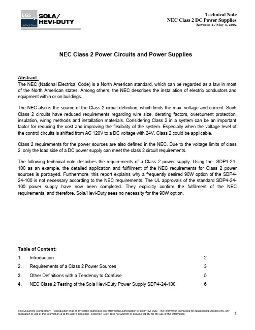
NEC Class 2 Power Circuits and Power SuppliesAbstract:The NEC (National Electrical Code) is a North American standard, which can be regarded as a law in most of the North American states. Among others, the NEC describes the installation of electric conductors and equipment within or on buildings.The NEC also is the source of the Class 2 circuit definition, which limits the max. voltage and current. Such Class 2 circuits have reduced requirements regarding wire size, derating factors, overcurrent protection, insulation, wiring methods and installation materials. Considering Class 2 in a system can be an important factor for reducing the cost and improving the flexibility of the system. Especially when the voltage level of the control circuits is shifted from AC 120V to a DC voltage with 24V, Class 2 could be applicable.Class 2 requirements for the power sources are also defined in the NEC. Due to the voltage limits of class 2, only the load side of a DC power supply can meet the class 2 circuit requirements.The following technical note describes the requirements of a Class 2 power supply. Using the SDP4-24-100 as an example, the detailed application and fulfillment of the NEC requirements for Class 2 power sources is portrayed. Furthermore, this report explains why a frequently desired 90W option of the SDP4-24-100 is not necessary according to the NEC requirements. The UL approvals of the standard SDP4-24-100 power supply have now been completed. They explicitly confirm the fulfillment of the NEC requirements, and therefore, Sola/Hevi-Duty sees no necessity for the 90W option.Table of Content:1. Introduction 22. Requirements of a Class 2 Power Sources 33. Other Definitions with a Tendency to Confuse 54. NEC Class 2 Testing of the Sola Hevi-Duty Power Supply SDP4-24-100 61 Introduction:The NEC (National Electrical Code) is a North American standard, which can be regarded as a law in most North American states. The NEC is developed through a consensus process by the NFPA (National Fire Protection Association). The NFPA 70 document and the NEC are the same. Compared to UL Standards – which covers requirements of devices -, the NEC takes care of electric conductors and installation methods within or on public and private buildings (and structures).The NEC Code is published in the NEC Code Book, which is released every three years. The current version is the Code Book of the year 2002. All data of this Technical Note corresponds with this version.The NEC is the source of the Class 2 circuit definition as well as for the Class 2 Power Supply definition. Class 2 defines the portion of the wiring system between the load side of a Class 2 Power Supply (beginning from the outside of a cabinet or machine) and the connected equipment. Due to its power, current and voltage limitations, a class 2 circuit considers safety from a fire initiation standpoint and provides acceptable protection against electric shock.The NEC is not harmonized with other countries. Similar standards exist in Germany (VDE 0100), Canada (CSA C 22.1), Switzerland (SEV HV1000), Great Britain (BS7671) or as international standards (IEC 364-…). None of the other countries have any comparable to a Class 2 definition. Class 2 can be regarded as a North American specialty, which is applicable in the USA, in states using American standards or when other countries ship their products to such areas.Only the load side of a power supply with a nameplate rating of less than 100VA (or 5 times Vout if output voltage is lower than 20V) can meet the class 2 circuit requirements.Such Class 2 circuits have reduced requirements regarding insulation, wire size, derating factors, overcurrent protection, wiring methods and installation materials. Considering Class 2 in a system can be an important factor for reducing the cost and improving the flexibility of the system. Especially when the voltage level of the control circuits is shifted from AC 120V to a DC voltage with 24V, Class 2 can be applicable resulting in a huge benefit.A short installation guideline for Class 2 circuits follows:- Class 2 requires dry indoor use- Only for non hazardous location areas- Circuits shall be grounded- Two or more Class 2 circuits are permitted within the same cable, enclosure or raceway- Separate Class 2 circuits from other circuitsFor details, please refer to the NEC Codebook.2 Requirements of a Class 2 Power SourcesThe many existing, superficial statements coming from questionable sources create a lot of confusion! Please, before you start reading this chapter, forget everything you have heard about Class 2 and read the following information with an open mind.Therefore, in this Technical Note we will start at the beginning. This is not as difficult and complex as many may think.The sole criteria for determining whether a Power Source is class 2 or not can be found in the NEC Article 725-41a):____________________________________________________________________________________________________________________________________________________________________________________________________________________________Here, you find five options (1. to 5.).Option 1 is applicable to transformers only; Option 3 is important for equipment builders, who benefit from a Class 2 power source; and Option 5 applies only to batteries. These three options do not apply to a Sola/Hevi-Duty power supply.Option 4 refers to the UL1950 chapter 2.5 “limited power circuits”. The fulfillment of this requirement is one way to achieve a NEC Class 2 listing. “Limited power circuit” means, that even in a single failure condition, the output power is limited to 5xVout (Vout ? 5V) or 100VA. This is much tougher than NEC requires and results in power supplies that have a nameplate rating of only 90W or less. This margin in power is necessary for the additional protection circuit to always stay below the 100W in case of a single failure. Sola/Hevi-Duty usually tests safety issues according to this UL 1950 (UL 60950) standard and for power supplies having a rated output power of up to 60W, this option is useful because it is included in thestandard UL 1950 (UL 60950) test procedure. For power supplies with a rated output power (nameplate rating) between 60 and 100W, it is not useful, because a very precise and costly protection circuitry is required. In such cases it is better to use Option 2.Option 2 calls for a listed Class 2 power supply. This means that you have to apply table 11(a) and 11(b) in chapter 9 of NEC. Table 11(a) covers devices with AC output (class 2 transformers), 11(b) covers power supplies with DC output. Sola/Hevi-Duty only has DC power supplies, not Class 2 transformers, therefore only table 11(b) will be further considered.______________________________________________________________________________________________________________Some comments to understand the table:Class 2 versus Class 3:Class 2 considers safety from a fire initiation standpoint and provides acceptable protection from electric shock.Class 3 considers safety only from a fire initiation standpoint. The output voltage can reach values up to100Vdc on a 100VA power level, which is not typical for Sola/Hevi-Duty power supplies.Inherently Limited versus Not Inherently Limited Power Source:Inherently limited means that the power source itself limits the output current (e.g.: using a electronic or magnetic circuitry). All Sola/Hevi-Duty power supplies are inherently limited.Not inherently limited means that an additional protection device (usually a mechanical circuit breaker or fuse) protects against overload within a defined time. The additional protection device must be installed within or closely connected to the power source, so that it can be regarded as one unit.The maximum power source nameplate rating for a Class 2 power supply is 100W (or 5 times Vout if the output voltage is in the range from 0 to 20Vdc). Similar requirements exist for the maximum nameplaterating of the output current: 5A for output voltages up to 20Vdc or 100 divided by Vout for voltages above 20Vdc.I n case of a single failure of the voltage regulator or current limitation circuitry inside the power supply, the max. output current values according to I max from table 11b apply. The output current at any load must be smaller than I max.Option 2 (listed Class 2 power supply) is easier to achieve than option 4 (limited power circuit acc. UL 1950). The following graph shows a comparison of NEC Class 2 I max limits with UL 60950 limited power circuit requirements:The UL 60950 limits are taken directly from the table 2B of UL 1950 or are calculated from the max apparent power divided by the voltage of this table.3 Other Definitions with a Tendency to ConfuseUL 508 chapter 32.7 “Limited energy circuits”:Has nothing to do with NEC Class 2. Requirement on power sources are less strict compared to the NEC. Volt-ampere capacity is limited to 200VA; voltage is limited to 100Vac.UL 60950 (UL 1950) or IEC 60950 chapter 2.5 “Limited power source”Can be one option to achieve NEC Class 2. The requirements are tougher than NEC. The output power is limited to 5xVout (for outputs less than 20Vdc) or 100VA, even in case of failure of the voltage or current regulator or any other single component.UL 1310 Class 2 Power UnitsUL 1310 is the governing standard for Class 2.These products provide Class 2 power levels in accordance with the NEC and apply to direct plug-in power units and cord-connected power units. A typical Sola/Hevi-Duty power supply for industrial purposes is not covered by this standard.UL 3101 (EN 61010) Electrical Equipment for Laboratory UseAnnex F defines limited power circuits. The requirements are similar to the NEC, but the nameplate rating is not limited to 100VA (can go up to 150VA). Not an option for NEC Class 2.UL 1585 Class 2 and Class 3 TransformerConforms to the NEC and can be used as an option. But a DC power supply can not be considered as a transformer.Class II protection of electric shock (in German: Schutzklasse II)Is not subject to any limited power characteristic. It defines, that all touchable parts of equipment areisolated by double or reinforced insulation.Class I Div 2Is not subject to any limited power characteristic. It is a definition in the standard for safety for electrical equipment for use in hazardous (classified) locationsPollution degree class 2Environmental conditionOvervoltage Category IIDescribes transients on the input mains4 NEC Class 2 Testing of the Sola Power Supply SDP4-24-100Frequently a 90W Class 2 option of the 100W SDP4-24-100 unit has been requested. A close study of the NEC Class 2 requirements revealed, that there is no necessity for a 90W model. During the UL certification procedure, the standard SDP4-24-100 has been tested according to the NEC Class 2 and fulfills the requirements. The UL report states:“Unit does not fulfill requirements of UL 60950 for Limited Power Source.Unit meets requirements of NEC Class 2 power source”.Therefore you can regard the SDP4-24-100 as a listed Class 2 power supply. On the rating label of the unit, we will add the following text: “NEC Class 2 Power Supply”.Benefits of reducing it to one model are:- Reduced stock keeping- Full 100W available- No additional costs- All other features, such as adjustable output voltage, single / parallel mode are availableThe following graph shows the measurement results of the NEC Class 2 testing:Curve (1) shows the standard load behavior of the SDP4-24-100 set to 24.5V output voltage. In the range from 0A to 4.6A, the output voltage regulator stabilizes the output voltage. Above this range, the current limitation circuitry limits the output current.Curve (2) shows the behavior when the output voltage regulator fails. The output voltage increases to approx 34.5V and is regulated to this value by a redundant voltage regulator. This redundant voltage regulator works with a “hiccup mode,” which means, that the voltage stays at that level only for a short period of time before it shuts down. Automatic start-up attempts follow.In case of a failure of the current limitation circuitry, the input fuse will blow and the output will go to zero. Curve (3) shows the limits of the NEC Class 2.The above curves were tested at different input voltages and temperatures.As long as the additional fulfillment of the “Limited Power Circuit” of EN60950 is not demanded, we will not launch a separate 90W model (SDP4-24-100A) as previously planned.U.S.A................................................................ (800) 377-4384International………………………………………(847) 679-7800While every precaution has been taken to ensure accuracy and completeness in this manual, Sola/Hevi-Duty assumes no responsibility, and disclaims all liability for damages resulting from use of this information or for any errors or omissions.© 2002 Sola/Hevi-Duty. All rights reserved throughout the world.Specifications are subject to change without notice.® Sola/Hevi-Duty name and logo are registered trademarks of EGSElectrical Group, LLC. All names referred to are trademarks orregistered trademarks of their respective owners.S0I-23237 (18042002) Rev. 1。
iTeach 桌面充电器用户手册说明书

iTeach® Desktop ChargerOwner’s ManualA Ventilation slots on either side of unitB 8 easy load slotsC LED charge indicators D USB port for device cableE Power on/off switch FPower cordPhysical FeaturesLEDs shown lit for illustration purposes only.Physical Fea▪Test the branch circuit for ground integrity and branch circuit protection.▪Do not plug in the unit if the power cord has been damaged, or if the ground prong is missing from the AC plug. If repairs are ever needed, they should be performed by a quali ed electrician.Safety First!▪This unit must always be used by adults or with adult supervision.▪Liquids should not be in, on, or around the iTeach Desktop Charger. ▪Do not use outdoors.▪Do not use the unit if the cord appears to be damaged or if the ground prong is missing.▪Do not use an extension cord with this unit.are powering the unit properly and in accordance to the unit's speci cations and requirements.▪Read owner’s manual and understand safe useguidelines before operating to ensure personal safety. ▪Plug AC power cord into wall outlet. Unit will power ON.▪Red LED indicators should be lit to indicate power to the unit.▪Plug desired device cords into exposed USB ports. ▪Slide up to 8 devices into slots and plug corresponding cord into device.▪LED indicators will change color based on charge time of device. See technical specs on page 5 for LED charging indication.information.Before using the iTeach Desktop Charger, it must be plugged into an AC outlet (100-120 VAC, 60Hz) with a minimum of 15 Amp rating. The iTeach Desktop Charger uses a maximum of 10.0 Amps, but should be powered by an outlet with extra capacity.Each charging port consists of a row of four LEDs anda charging cable ending with a female USB Type A connector. In order to charge a particular type of device, the corresponding style cable must be plugged into the charging cable. For example, an Apple iPad cable is required for charging an iPad.As a tablet is charged, additional blue LEDs will appear to indicate charging time. One blue LED is visible for the initial 90 minutes (1.5 hours) of charging. After 90 minutes, a second blue LED appears. Once an additional 90 minutes has passed, a third blue LED lights up. The fourth blue LED becomes visible after the tablet has been charged 4.5 hours.2 blue LEDs: tablet connected, charge time between1.5 and 3 hours3 blue LEDs: tablet connected, charge time between3 and 4.5 hours4 blue LEDs: tablet connected, charge time morethan 4.5 hoursAny time the iTeach Desktop Charger has power, each port should display one of the LED indications above.In the event that the iTeach Desktop Charger is plugged into an AC outlet without lighting any LEDs, the unit is not receiving power. This can be caused by a blown fuse located inside the iTeach Desktop Charger, or by a problem with the AC outlet (such as a blown breaker). In such circumstances, a properly trained technician should be contacted to address the situation.Unit Use▪MooreCo, Inc. does not accept liability for damage to unit if misused, inadequately repaired, or modi ed.Any of the above will void warranty.▪Use of unit is intended for adults only. Do not allow use by children or students unless fully supervisedby a responsible adult.▪Unit is designed for indoor use only.▪Be sure all external power cords are unplugged and correctly stored before moving unit.▪Do not run cords in high traf c areas or through doorways, hallways, holes in ceilings, walls, or oors.Electrical SafetyWARNING: Failure to followelectrical guidelines may resultin fi re, injury, or electrical shock.▪Be sure not to exceed electrical rating of 10 amps. ▪Do not plug in or use unit if any power plug or electrical cord has been damaged.▪Contact MooreCo or quali ed electrician before attempting to perform any sort of maintenance ormodi cation to unit electronics.▪Do not plug unit into extension cord or movable power strip.▪Do not remove or modify any prongs or pins of power cord in any way.▪Keep all liquids away from unit. Do not use unit if wet.▪Do not operate near ammable materials.▪Do not block ventilation of unit. Proper air ow isrequired to avoid overheating or damage to unit.NotesBalt ® & Best-Rite ® are brand divisions of MooreCo Inc.2885 Lorraine Ave Temple, TX 76501p: 800.749.2258f: 。
5230使用各种技巧

C:\Data\Installs E:\Installs 是安装软件存放的目录,可以清空
C:\System\data\music.db 音乐索引文件的数据库
C:\System\System.ini 这个文件会自然增长,每次开机都会先读它,删除后重启手机,文件会自动重建,个头会小很多。
其它还有很多目录,不过未XX的手机比较难删,有些干脆就找不到,所以不列举了……
自带浏览器清除缓存的方法:打开浏览器→选项→清除保密数据→全部(最起码:缓冲存储+历史记录)
UC浏览器清除缓存的方法:打开浏览器→工具→清除记录→全选(最起码:访问历史+页面缓存)
所有的图片目录下,都有一个_PAIBTN的隐藏目录,是存放图片浏览器缩略图的地方,定期删除。
(_PAIBTN中,会保留着你早已删除的图片的缩略图。此文件夹删除后,打开图片浏览器就会自动创建)
在输入文字状态,点“三”,将“字符预览”关闭。
功能表→设置→个人模式→主题模式→标准→点左下选项→主题模式效果·关。
日历提速法(要注意正解的用法哦)——新机或相当一段时间日历没有内容时,可用此法:
日历→新日历项→待办事项→主题:Speed→预定日期:2010-01-21(yyyy-mm-dd)→优先等级:高。
功能表→设置→个人模式→情景模式→标准→个性化选择→振动提示→关
功能表→设置→个人模式→情景模式→标准→个性化选择→触摸屏震动→关
(个人喜欢把按键音也关掉,反正小5也没几个键……)
功能表→设置→手机→屏幕显示→亮度→30-40%(晚上甚至可以到20%)
功能表→设置→手机→屏幕显示→背光延续时间→20-30秒
功能表→设置→连接功能→网络→运营商选择→手动→移动/联通
TC3582B资料及电路
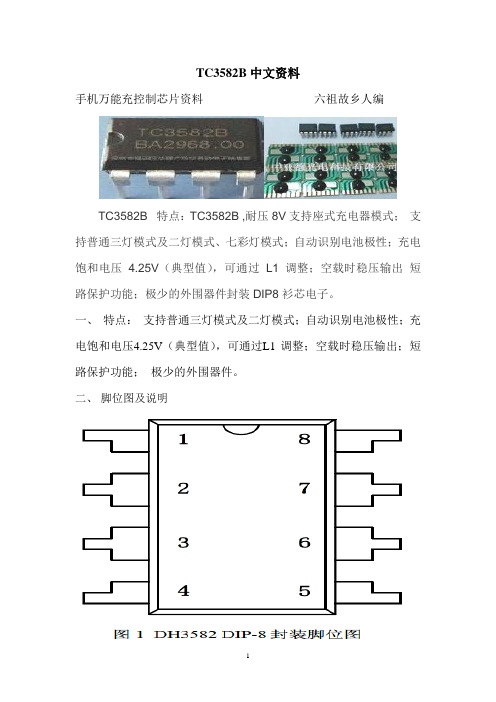
TC3582B中文资料手机万能充控制芯片资料六祖故乡人编TC3582B 特点:TC3582B ,耐压8V支持座式充电器模式;支持普通三灯模式及二灯模式、七彩灯模式;自动识别电池极性;充电饱和电压 4.25V(典型值),可通过L1 调整;空载时稳压输出短路保护功能;极少的外围器件封装DIP8衫芯电子。
一、特点:支持普通三灯模式及二灯模式;自动识别电池极性;充电饱和电压4.25V(典型值),可通过L1 调整;空载时稳压输出;短路保护功能;极少的外围器件。
二、脚位图及说明三、应用电路图及功能描述(*)电源指示灯L1 应选取开启电压为1.85V~1.90V(在2mA 电流下测量)的LED。
(**)此处为负值,表示此时电池向电路放电(为L1 供电)(***)表格中所列数据均为典型值。
1、电池检测在电源断开的情况下接入电池,DH3582 会通过自动“极性识别”系统对电池进行相应控制,使电池检测指示灯L1 亮,状态参见表1 的描述。
2、电池空载当电源连通而尚未接入电池时,BTP 和BTN 两端之间的电压差为4.17V(典型值),L1、L2 的状态参见表1 的描述。
3、正常充电及饱和检测。
电源连通并且接入未满电池时,电源开始通过DH3582 的控制对电池进行正常充电(如前所述,此时不论电池以何种极性接入电路,均能正常充电),充电电流约为130mA(典型值),电池两端电压缓缓升高,当电池电压升高到4.25V(典型值)时,充电过程结束,电池已饱和。
此过程中L2 的状态参见表1 的描述。
4、短路保护若在电源接入后发生电池短路的情况,则DH3582 内部“短路保护”系统会自动将充电回路切断,避免产生大电流。
此时L1、L2 状态参见表1 的描述。
四、典型参数(除特殊说明外,所胡参数均在室温下测得,并以GND 端电位为0 电位)TC3852B手机万能充电应用电路图3G商务万能座充(深圳市东亿通电子科技有限公司)【六祖故乡人制作】元件:D1:1N4007;D2:1N4148;D4:1N5819;Z1:1N4734A(5.6V/810mA);C1:1μ/400V;C2::2.2μ/50V;C3:102PF/60V;C4:220μ/16V;C5、C6:104PF/60V;R1:1MΩ/1/8W;R2:10KΩ/1/8W;R3、R4:47Ω/1/8W;R5:1Ω/1W;U1:TC3582B(双列直插);Q1:13002;T1:(高频变压器)L1:9Ω、L:0.7Ω、L3:0.1Ω;H1、H2:LED(发光二极管)。
索尼 充电保护套 CP12 用户指南说明书
用户指南充电保护套简介 (3)充电方便 (3)说明书 (3)使用充电保护套 (4)手机充电 (4)法律信息 (6)充电方便利用充电保护套,您不用打开手机的微型USB充电端口盖即可给Xperia™智能手机充电。
充电保护套采用一种内置电池,您可以提前给它充电,然后当您出门在外或手机电池电量不足时使用它给您的手机供电。
当您的手机连接到充电保护套之后,您也可以直接从电源为手机充电。
1手写笔2指示灯3电源按钮为避免火灾和电击风险,请仅在干燥的环境中使用此配件。
请勿拆开和重新组装此配件。
使用前请阅读安全信息。
说明书电池锂电池容量3,000毫安时/3.8伏尺寸(毫米)186.2 × 16.6 × 111.3(宽/高/深)重量290克最大输出电流1安额定输出电压5伏直流工作温度–10 °C至45 °C使用充电保护套充电保护套配件有两种模式:电源模式和充电模式。
当您使用保护套的内置电池为手机充电时,充电保护套处于电源模式。
当您使用保护套的交流适配器和电源为手机充电时,保护套处于充电模式。
若保护套在电源模式下工作,您必须先为保护套的内置电池充电。
手机充电为充电保护套充电1确保智能手机已从充电保护套中取出。
2将充电器电缆的磁性端插入充电保护套。
3将电缆的USB端插入交流适配器。
4将交流适配器插入电源插座中。
如果您将充电器电缆插头插入计算机的USB端口,手机或充电保护套则不会充电。
使用充电保护套为智能手机充电为防止损坏,在将手机连接到充电保护套之前,请先擦除任何灰尘或污物。
1确保充电保护套已充满电。
2将智能手机放到充电保护套中,使手机侧面的接口与充电保护套中的接口相接触。
3按电源按钮开始为智能手机供电。
如果在将手机连接到保护套时指示灯闪烁红色,请取出手机并确认没有物品卡在接口之间或挡住接口。
金属或其他物品挡住接口可能会造成短路。
确认充电保护套未损坏,且未超过工作温度范围,然后重复步骤连接您的手机并给它充电。
Waydoo Flyer ONE Plus系列产品说明书

Explorer/Patroller 动力单元说明书目录免责声明Explorer/ Patroller 动力单元部件安装步骤便携箱如何使用维护保养安全指引故障解决方案免责声明使用前请仔细阅读本使用手册及相关警示,本产品为水上运动器材,使用本产品存在可能导致严重伤害甚至死亡的内在风险,使用本产品的用户须理解并接受使用本产品的固有风险,任何超出对本产品设计限制的滥用都可能导致产品损坏或人身伤害,作为产品开发的持续不懈努力,苇渡保留在不提前通知的情况下更改本产品的组件、规格或其他方面的权利,若了解最新资料 , 请浏览 : 。
包装清单充电器动力单元遥控器+遥控器+充电线充电器电源线工具包手腕带Waydoo Flyer ONE PlusWaydoo Flyer ONE Plus系列产品是Waydoo Flyer ONE的升级水翼板产品。
该系列包括智能电池、板体、动力单元、水翼等子产品。
这四个子产品需要组合以形成一套完整的水翼板产品。
用户可以根据自己的骑行需求自由选配。
除了 充电器、智能电池和水翼外,我们不建议用户将 Waydoo Flyer ONE 的子产品与 Flyer ONE Plus 的子产品混合搭配使用。
本手册是动力单元的说明书。
Explorer/Patroller 动力单元在本手册中统称为动力单元。
部件遥控器+采用人体工学设计,采用 LCD 显示界面。
显示内容分别为 智能电池和 遥控器+的电量,蓝牙连接和飞行速度。
它提供24档位供调节。
1. 从工具包中取出遥控器充电线。
2. 充电线一端插入 USB 充电器,将磁吸充电接头连接到 遥控器+, 充电接头自动吸附即可充电。
3.遥控器+正常充电时,顶部的灯会亮起。
充电时长为3小时。
6. 扳 机7. 指示灯遥控器+显示屏1. 遥控器+电量2. 速度3.智能电池电量4. 蓝牙连接5. 速度档位备注:1. 开启 遥控器+:按住 遥控器上的电源键5 秒钟,直到屏幕完全亮起。
电子元件清单及价格
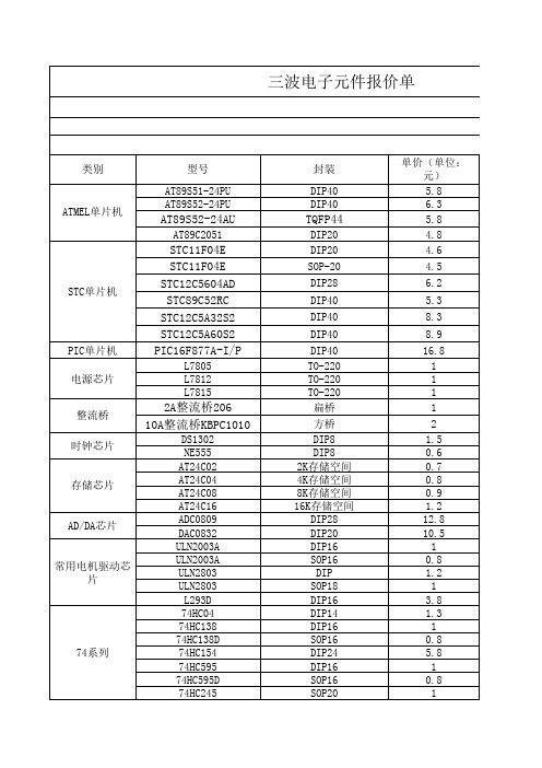
数字万用表套件 万能充套件
声光控灯头套件
支持S51\S52\AVR\STC 等 有ISP功能的单片机
5W 5W 10W S66D/S66E DT830B
15.6
2
2
7.8
25.8
22.5 10 8.5 10 11.5 12.8 12.8 16 10 16 8.6 4.9
教学实验套件
面包板用试验线
感光板 铜箔板/覆铜板
热转印纸 显影剂 腐蚀剂
常用工具
金电子单面感光板 单面覆铜板 单面覆铜板 热转印纸 感光板显影剂
蓝色环保腐蚀剂 三氯化铁腐蚀剂
20W热熔胶抢 20W内热平头烙铁 40W内热平头烙铁 60W内热平头烙铁 数字游标卡尺0-150mm
迷你电钻套装
每把75根,十元
10*15 7*9 9*15 A4 50g 190g 500g 20W 20W 40W 60W 0-150mm
TO-92 TO-92 TO-92 TO-92 TO-92 TO-92
DIP8 DIP14 TO-92 TO-220 TO-220 SOT82 TO-220 TO-220 TO-220 TO-220 TO-220 TO-220 TO-220 红色
黄 蓝色 绿色 白色 紫色(验钞) 红色 绿色 红色 绿色 共阴/共阳 共阴/共阳 共阴/共阳 共阴/共阳 共阴/共阳 3线控制、静态显示 3线控制、静态显示 绿底黑字 蓝底白字 绿底黑字
单价(单位: 元) 5.8 6.3 5.8 4.8 4.6
4.5
6.2
5.3
8.3
8.9
16.8 1 1 1 1
2 1.5 0.6 0.7 0.8 0.9 1.2 12.8 10.5 1 0.8 1.2 1 3.8 1.3 1 0.8 5.8 1 0.8 1
WD My Passport Wireless SSD 250GB移动存储设备 使用说明书
My Passport® Wireless Pro 和My Passport® Wireless SSD Wi-Fi® 硬盘用户手册获取在线支持▪在线学习中心- 由此开始,充分利用您的个人云存储设备:/setup。
▪注册- 访问注册 WD 产品以获得最新的更新内容并享受特别优惠▪ji数支持–访问/support,通过电子邮件获得技术和其他支持▪保修与 RMA 服务- 访问/warranty获取保修、产品退换 (RMA)、RMA 状态、配件以及数据恢复信息▪知识库–访问/knowledgebase通过关键字、词组或 Answer ID 搜索▪WD 社区–访问与其他 WD 用户分享您的想法和建立联系▪电话支持–访问获取联系各区域支持人员的电话号码目录_________获取在线支持 (ii)_________1 关于您的 WD 存储设备 (1)操作注意事项 (1)套件内容 (1)可选配件 (1)关于在线学习中心 (1)系统要求和浏览器 (2)操作系统 (2)Web 浏览器 (2)产品组件 (3)My Passport Wireless Pro/My Passport Wireless SSD(俯视图) (3)My Passport Wireless Pro/My Passport Wireless SSD(后视图) (3)_________2 了解 LED 和按钮 (5)电源和电池状态 LED (5)My Passport Wireless Pro/My Passport Wireless SSD 电源和电池状态 (5)Wi-Fi LED (6)SD/USB 导入过程中的 LED 活动 (6)其他 LED 行为 (6)按钮 (7)_________3 设置无线硬盘 (8)开启硬盘 (8)首次设置硬盘 (8)使用计算机和 Web 浏览器 (8)关于面板 (11)在移动设备上使用 WD My Cloud 应用 (11)_________4 面板一览 (12)启动面板 (12)面板主页 (12)信息图标 (13)导航图标 (14)在主页上查看硬盘状态 (14)电池 (15)Wi-Fi (15)信息 (15)_________5 连接硬盘 (17)连接概述 (17)进行直接无线连接 (18)使用 Web 浏览器进行无线连接 (18)连接至家庭 Wi-Fi 网络和互联网 (19)建立家庭 Wi-Fi 连接(互联网访问) (19)删除 Wi-Fi 连接 (21)共享和修改 Wi-Fi 连接 (21)查看或更改硬盘的高级 Wi-Fi 设置 (22)接入点设置 (23)_________6 将内容加载到您的硬盘上 (26)使用 USB 连接加载内容 (26)使用 Wi-Fi 连接加载内容 (26)同一网络上的设备 (26)移动设备(使用 WD My Cloud) (27)使用兼容无线相机 (27)启用 FTP 访问 (27)将计算机备份到硬盘 (28)备份 Mac 计算机 (28)备份 PC (29)_________7 与硬盘一起使用 SD™卡 (30)手动从 SD 卡复制数据 (30)自动从 SD 卡复制数据 (32)从 SD 卡复制所有文件/复制新文件 (32)查看从 SD 卡导入的内容 (32)查看从 USB 硬盘导入的内容 (33)_________8 播放/流式传输视频和照片 (34)使用硬盘作为媒体服务器 (34)启用媒体流式传输 (34)将硬盘与 Plex Media Server 搭配使用 (34)Twonky®服务器 (35)内容计数 (35)使用媒体播放器访问您的内容 (36)WD 媒体播放器 (36)将硬盘与支持 DLNA 的移动应用搭配使用 (36)_________9 使用电池 (37)延长电池续航时间或提高性能 (37)给电池充电 (37)在硬盘关闭时查看电池状态 (38)_________10 执行管理功能 (39)更改密码和设备名称 (39)更改语言 (40)指定访问类型 (40)锁定硬盘 (41)重启和关闭硬盘 (41)保存 My Passport Wireless Pro/My Passport Wireless SSD 的快捷方式 (41)_________11 重置您的硬盘和密码 (42)手动重置硬盘 (42)使用面板还原出厂设置 (42)_________12 更新固件 (44)查看固件版本 (44)使用可用固件更新 (44)执行手动更新 (45)_________13 获取支持 (46)系统报告 (46)诊断 (47)产品改进计划 (47)_________14 问题与解决方案 (48)密码 (48)名称 (48)连接 (48)电池和性能 (49)硬盘格式 (50)_________附录 A 技术规格 (51)_________附录 B 兼容的媒体格式 (53)_________附录 C 法规信息 (54)安全符合性 (54)符合欧洲 CE 标准 (54)环境符合性(中国) (54)Russia Federation (54)加拿大 (54)US (55)ICES-003/NMB-003 声明 (56)Korea (56)台湾地区 (56)1关于您的 WD 存储设备本章包括以下主题:操作注意事项套件内容可选配件关于在线学习中心系统要求和浏览器产品组件操作注意事项WD 产品属于精密设备,在拆箱及安装时必须小心。
特纳 i-charge 2 电池充电器用户手册说明书

i-charge 2 Array Battery chargerUser manualModel Part No.1264543Tennant Company10400 Clean Street, Eden Prairie,MN 55344-2650Telephone: (800) 553-8033Internet: To view, print, download the partsmanual visit:/manualsRevision: 00 (10/2022)Original user manual, written in the English Language Tennant Company10400 Clean Street, Eden Prairie, MN 55344-2650 Telephone: (800)553-8033 Internet: Date:26/10/2022 Model: i-charge 2Product code: 1264543Version: v.1.0PrefaceThank you for purchasing the i-charge® 2. The i-charge 2 is made to charge i-power batteries in a short amount of time. The quick exchange i-power battery system makes our battery powered machines a real cleaning workforce.The i-charge 2 is easy to use when you follow the instructions. Please read the user manual carefully. Become familiar with the correct operation and maintenance procedures. Store the manual in a safe place. The manual is an essential part of the i-charge 2 and must be handed over to the new owner upon resale or exchange. Each i-charge 2 has a unique identification number that can be found on the bottom.Purpose of the user manualThe purpose of the user manual is to provide the user with information during the life of the i-charge 2 in such a way that the i-charge 2 is used correctly, efficiently and safely, even in the event of reasonably foreseeable misuse.The user manual contains instructions regarding:•personal operator safety;•intended and non-intended use of the i-charge 2;•instructions for daily use;•maintenance instructions;•storage conditions;•disposal of the i-charge 2.These instructions must be considered to avoid risks that could lead to physical and/or material damage.Target audienceThis user manual is intended for operators of the i-charge 2 and their supervisors, as well as partners and importers.Operators of the i-charge 2The i-charge 2 may only be operated by a person who:•has correctly read and understood the instructions in this manual;•is trained by an experienced operator who has read and understood the instructions in this manual.Reading guideThe following symbols and terms are used throughout this manual to alert the reader to safety issues and important information:ContentPreface (3)Purpose of the user manual (3)Target audience (3)Operators of the i-charge 2 (3)Reading guide (4)1Introduction (7)1.1Intended use of the product (7)1.2Non-intended use of the product (7)1.3Modifications (7)1.4Specifications (8)1.5Warranty (9)1.6Identification (9)2Description (10)2.1Battery charge displays (11)3Safety (12)3.1General Safety Instructions (12)3.1.1Batteries (12)3.2Risks during operation (13)4Transport and storage (14)5Assembly and installation (15)5.1Unboxing (15)5.2Assembly (16)6Operation (17)6.1Before you start (17)6.2Operation (17)6.2.1After operation (18)6.3Cleaning and storage (18)6.3.1Cleaning (18)6.3.2Storage (18)7Maintenance (19)8Trouble shooting (20)9Decommissioning and disposal (21)1IntroductionThe i-charge® 2 is easy and safe to use. You will be surprised how fast and effective the i-charge 2 is. This manual helps you get started and explains the operation and maintenance procedure.This manual is intended for those who work with the i-charge 2 and perform daily maintenance. The manual must be read in full before the first actions. This manual describes the correct method of use, safety measures, maintenance and transport.The manufacturer continuously improves all their products based on user experience and feedback. Any deviations between the texts and/or images from the manual and your i-charge 2 can therefore arise from the difference in model or from possible changes due to continuous development and innovation.1.1Intended use of the productThe i-charge 2 should be used indoors in a dry and well ventilated open environment. ONLY use original Lithium - Ion batteries provided by the manufacturer.The i-charge 2 is not intended for use outdoors or in a wet or closed environment.Do not charge non original batteries or non-rechargeable batteries with the i-charge 2. Alternative products will void the manufacturer’s warranty, more importantly they may also cause serious harm to the operator. Non-original batteries, for instance, can burst open.1.3ModificationsIt is not permitted to make modifications to the design of the i-charge 2 without consultation and permission from the manufacturer. This affects the warranty, see section 1.5.1.4SpecificationsFigure 1Product size: 265 x 214 x 110 mm | 10.4”x 8.4 “x 4.3”Weight: 1.2 kg | 2.6 lbsBattery capacity: 2 batteries/63 HzPower supply: 100-240 V, 50/60 Hz per sideFuse 6.3 A / 300msCharge current: 2.5 A per sideStandby power: 2 WAverage charging time: i-power 9: 4 hours ; i-power 14: 6 hours Operation temperature and humidity: 10 C - 50 C : 20% - 90% RH, no condensing Storage temperature and humidity: 10 C - 85 C : 10% - 95% RH, no condensing Output voltage: DC 29.4 V per side1.5WarrantyThe i-charge® 2 should only be operated with the materials supplied. Using alternative supplies may cause damage to the i-charge 2 and may cause a risk to the operator. The use of alternative supplies voids manufacturer's warranty.1.6IdentificationEach i-charge 2 has a unique serial number that can be found on the bottom of the body. Your i-team partner needs this number when you order parts.Explanation type plate:Figure 22DescriptionThe compact i-charge® 2 is designed to charge 2 batteries in parallel. The i-charge 2 consists of:Figure 3Legend1. The battery charge displays.2. The power cable.3. The main body.4. The ON/OFF switch.2.1Battery charge displays1.Battery charge displays. When thecolored bars will go up from one bar thatblinks, which indicates that the batteriesare almost empty. To three bars thatburn continuously, which indicates thatthe batteries are full and ready to use.Figure 43SafetySafety comes first, therefore please take time to read and understand these safety instructions. Improper use can cause harm or void the manufacturer’s warranty.3.1.1Batteries•do not block the cooling fan inlet;•do not remove the warning decals;•do not use the power cable to unplug- or to carry the i-charge 2;•do not charge wet or damaged batteries;•do not cover the i-charge 2 during usage;•ensure that the main voltage is identical to that mentioned on the identification plate on the i-charge 2;•only use the i-charge 2 in an environment that is well ventilated and has a good heat dissipation.4Transport and storage5Assembly and installation 5.1UnboxingThe i-charge® 2 is packed in 1 box.Figure 5Legend1. 1x power cable2. 1x i-charge 2 battery charger3. 1x this user manual5.2AssemblyConnect the power cable (Figure 6, pos 1) to Array the connector at the back side of the i-charge 9.Figure 66Operation6.1Before you start•check the i-charge® 2 for damage;•check the power cable for damage, pull it through a fiber cloth; •check the battery for damage.6.2Operation1.Put the main power cable into the wallsocket (Figure 7, pos 1).2.Align each battery with the chargingdock (Figure 7, pos 2) and insert eachbattery, until you hear a "click". Thebatteries are ready for charging.3.Switch on the main switch from 0 to 1(Figure 8, pos. 2)4.The two displays (Figure 8, pos 1)indicate the charge level of the batteries.5.When the batteries are fully charged thedisplays indicate three bars. See alsosection2.1.6.Switch to 0 (figure 8, pos 2) when thebatteries are fully charged.Figure 7 Figure 87. Press the plastic clips of the battery(Figure 9, pos 1) slightly towards eachother.8. Pull out the batteries.Figure 9 6.2.1 After operation Wait 10 seconds after charging before you insert a new battery for loading. This will allow the memory of the i-charge® 2 to reset.6.3 Cleaning and storage6.3.1 Cleaning It is recommended to clean the i-charge 2 with a damp cloth every once in a while.6.3.2 Storage• store the i-charge 2 in a dry environment;• batteries can be stored separated from the charger or left on the charger. When left onthe charger the batteries will not drain;• Remove the battery before executing any maintenance task, or before storage.When the batteries are being charged, do not leave them permanently onthe charger.7MaintenanceMaintenance and repairs should only been done by authorized personnel.8Trouble shooting21 9 Decommissioning and disposalAt the end-of-life the i-charge 2 still contains valuable resources and needs to be disposed of according to your local laws and regulations regarding recycling of electrical equipment. Batteries also must be disposed of according to your local laws and regulations regarding recycling of electrical equipment. See also the User Manual of the i-power 9® and the i-power 14®.The packaging material is recyclable. Please do not dispose of it with household waste. Please recycle it. Old appliances contain valuable materials which can be recycled.Rechargeable battery packs contain materials which should not be disposed of in landfill. Please dispose of old appliances and batteries at the appropriate collection points.。
充电器加装防电池反接保护
充电器加装防电池反接保护电池组中单体电池损坏的主要原因是使用不当或管理失控造成的,大型电池组的寿命有时连单体电池的一半寿命都不到。
电池能量管理系统(BMS)是保证电动汽车安全、保持动力电源系统正常应用和提高电池寿命的一种相当重要的技术措施,称为电动汽车电池的“保护神”,它起到对电池性能的保护、防止个别电池的早期损坏的作用、有利于电动汽车的运行,并具有各种警告和保护功能等。
通过对电池箱内电池模块的监控工作使电动汽车的运行、充电等功能与电池的有关参数(电流、电压、内阻、容量)紧密相连并协调工作。
它有计算、发出指令、执行指令和提出警告的功能。
尤其是电池模块质量不太理想的条件下,应用功能完备的电池能量管理系统其作用就更加突出。
因此,电动汽车电池能量管理系统的应用备受电动汽车设计者和使用者的重视。
各种电池模块虽然有结构和性能上的差异,但它们都具备一些相同或相似的功能。
有些地方需要自动极性转换,有些地方只要防反接就可以了。
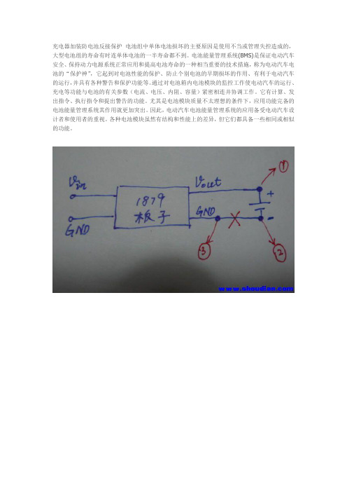
我DIY了几种18650充电器,都采用了1879,需要防反接,发现用以前买的4MOS自动极性电路套件改装,超简单,还可省下2只MOS管。
下图是没有防反接的1879充电示意图,加装防反接时,需要把红叉处刻断,并引出1,2、3三条引线。
下图是防反接原理图,是N-MOS接入的(P-MOS控制),所以是共正极(并联),而刻断负极(串联)。
下图是自动极性空PCB板,需要按图所示处理∶一只N-MOS,一只P-MOS,2只电阻,一处刻断,一处连通,三条引出线下图是已焊好,引出123三条引线,焊到第一个图上对应的支持!但是貌似防反接只要一个mos就够了吧这是个简单实用的防电池反接电路,动作可靠、压降极低、返流极小,几乎不影响1879的截止电压精度。
用4MOS自动极性散件改成,所以制作方便。
感觉1879防反接不自动极性好,更大程度减小了输出线阻,延长恒流的时间,缩短总的充电时间4MOS自动极性电路,始终有2只MOS工作在主电流回路中,一P一N,而防反电路只有一个MOS工作在主回路中。
WeDo 2
WeDo 21. 介绍WeDo 2.0 是一个教育机器人套件,旨在帮助孩子们研究和探索科学、技术、工程和数学(STEM)的基础知识。
为了开始进行WeDo 2.0 项目,您将需要准备特定的材料。
本文档将提供一个清单,列出了开始 WeDo 2.0 项目所需的基本材料。
2. 材料清单以下是进行 WeDo 2.0 项目所需的基本材料清单:1. WeDo2.0 套件- WeDo 2.0 套件包括一个主控模块、传感器和马达,以及其他相关部件。
请确保您拥有一个完整的 WeDo 2.0 套件。
- 如果您还没有购买 WeDo 2.0 套件,您可以在指定的零售商处或在线市场上购买。
2. 电脑或平板电脑- 您将需要一台带有 USB 接口的电脑或平板电脑。
这将用于与WeDo 2.0 主控模块进行连接和编程。
- 确保您的电脑或平板电脑有足够的存储空间和合适的操作系统来运行 WeDo 2.0 软件。
3. WeDo 2.0 软件4. USB 数据线- 准备一条 USB 数据线,用于将您的电脑或平板电脑与 WeDo 2.0 主控模块进行连接。
这条数据线将传输编程和控制的命令。
- 确保数据线的质量可靠,以避免传输故障。
5. 附加部件和材料- 根据您的项目需要,您可能需要准备一些额外的部件和材料,如积木、线缆等。
这将有助于您构建更复杂的模型和机器人。
- 可以根据您的项目计划提前准备好这些额外的材料。
3. 总结上述清单列出了开始进行 WeDo 2.0 项目所需的基本材料。
准备完整的 WeDo 2.0 套件、电脑或平板电脑、WeDo 2.0 软件、USB 数据线以及可能需要的附加部件和材料,将为您提供一个良好的开始。
祝您在 WeDo 2.0 项目中取得成功!。
NP-F970电池充电套件用户手册说明书
NP-F970Battery User ManualOverviewThe ZILR NP Battery has advanced technology to power your camera or external devices.Never miss a shot again due to low capacity batteries or waiting around for your next charge.What’s in the boxNP-F970USB-C PD BatteryProduct CodeZRNPB01Charging the NP-F970BatteryThe NP-F970battery should be charged using the recommended ZILR USB-C PD Wall Charger (ZRACC01*)and USB-C cable (ZRUCC01*).This will ensure that the battery is charged correctly and supports fast charging via this method.When using the Wall Charger (ZRACC01*),use the AC international adaptor plug for wall charger that matches your region.Recommended charging setupDo not overcharge.Do not expose the batteries and charger to fire or liquids.GettingStartedLED Charging IndicatorsNP-F970Battery LED Charging FunctionsThe NP-F970battery features LEDs to indicate the current charge level.Charging Full-100%Charging3/4-75%(Flashing/Blinking)Charging2/4-50%(Flashing/Blinking)Battery Insert Direction LED Indicators Output/Check Level Charging1/4-50%(Flashing/Blinking)NP-F970Battery LED Power Usage FunctionsThe NP-F970battery features LEDs to indicate the current power level while in use.Press the Output /Check Level button to view the current level.Battery Insert Direction LED Indicators Output /Check LevelLED Power IndicatorsIn Use Full -100%In Use 3/4-75%In Use 2/4-50%In Use 1/4-50%(Flashing/Blinking)NP-F970Battery on L-Series DevicesThe NP-F970battery can be used on L-Series devices using the standard 7.4V base terminal.Using the NP-F970on devicesConnect via the base terminalUse the NP battery slot on thedeviceConnect via the base terminal Connect via the USB-C port USB-C or Lightning device ORUse the NP battery slot on thedevice Press to outputpowerNP-F970Battery USB-C OutputThe USB-C output on the NP-F970battery can be used to power another device while in use.First connect the battery to the compatible NP battery/L-Series device via the device’s slot.Next plug in the USB-C to USB-C cable (ZRUCC01*)or the USB-C to Lightning cable (ZRUCL01*)to a USB-C or Lightning port on the second device.Press the Output Power button on the top of the NP-F970battery.The second device will then be powered from the battery.NOTE:Using two devices at one will drain the battery faster.Using the NP-F970with two devicesNP-F970Battery power bank modeThe NP-F970also doubles as a power bank,enabling charing of mobiles and tablets.The battery does not require to be connected to a L-Series device for this to work.Simply plug in the USB-C to USB-C cable (ZRUCC01*)or the USB-C to Lightning cable (ZRUCL01*)to a USB-C or Lightning port on the mobile or tablet.Press the Output Power button on the top of the NP-F970battery.The device will then be powered from the battery.The device will then charge.It also supports fast charging on devices that support this feature.Using the NP-F970as a powerbankNo L-Series device required USB-C or Lightning deviceORConnect via the USB-C port Press to outputpowerWarningOnly use ZILR accessories with this product as accessories from other manufactures have not been tested and may cause damage to your device.Do not over charge batteries.Do not use this product near water or get it wet as it could cause risk to you or the device.Do not expose batteries to heat or fire.Do not overload the power on this device.Supported Accessories-ZRACC01USB-C AC Wall Charger-ZRUCC01USB-C to USB-C cable-ZRUCL01USB-C or Lightning cable-ZRUCDB01USB-C to Sony NP-FZ100-ZRUCDB02USB-C to Panasonic DMW-DCC16-ZRUCDB03USB-C to Nikon EN-EL15-ZRUCDB04USB-C to Canon LP-E6Looking for further help?Please contact us should you require help or require more information.Contact us below:https://www.zilr.pro/support/Support!!!!!。
万能充组装说明V09
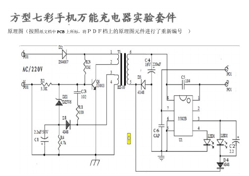
原理图(按照纸文档中PCB上所标,将PDF档上的原理图元件进行了重新编号),,这是元件安装图(按照纸文档给出的进行了修正):但看到的PCB是不透明的,如右图。
注意,有3个位置不装元件的:安装元件中,(一,)二极管的丝印图与安装时P,N极的对应关系:这个是开关二极管1N4148:可以看到元件外壳上印的”N”。
其中,黑边为N极。
安装前最好用表测一下极性。
这个是稳压管:可以看到”H6”(二,)电解电容的丝印图表示的极性如下:白色区为负极,电解电容元件外壳上,也是一般是用白色油漆内印“---“表示负极。
(三,)IC:IC(集成电路)安装时,封装上的缺口,对准白色丝印的缺口,我们这个PCB,丝印的缺口是向右的,所以,正着拿板的话,看到的IC上的字是颠倒的。
领取套件时,先向老师要求将IC 换成IC座,检查无误后,再插上IC 。
右面是集成电路(IC)的照片:缺口在左,。
左下角为1号脚,右下为4号脚。
(挡住无法看到的:右上为5号脚。
)座。
增加:8pin(四,)1. LED1 ,是发红光的,3mm的长脚为阳极,(从树脂封装内部看,小金属片为阳极。
)LED2是闪光的,5mm的,长脚按照阴极对待((!!!!后来发现看脚的长度有时会错,)可靠的方法还是从树脂封装内部看,小金属片为阳极。
),因闪光的LED实际上是一集成电路,严格地说就不应当再讲阳极阴极了),工作时电压2V左右(3V5时也能正常闪光),1-3ma都可正常工作。
(五,)板上唯一一个(分立元件)三极管(六,)这三个电阻:棕黑绿金:10*10^5=1MΩ,±5%误差黄蓝红金:47*10^2=4700Ω,±5%误差棕黑棕金:10*10^1=100Ω,±5%误差电容:102:10*10^2PF=1,000PF=1nf=0.001uf104:10*10^4PF=100,000PF=0.1ufBOM(物料清单):、建议每装一部分就调试一部分:(一)装R3, D2, Q1,在变压器的1,2 焊接孔上暂时装上LED1(3mm的, 长脚为阳极,接孔1,)此时的电路为:下面的调试中,一旦发现LED亮度迅速增加,必须马上将电源调回0.,否则损坏元件!。
Parker CADE 充电套件安装指南说明书

Installation Guide Charging KitsFAILURE OR IMPROPER SELECTION OR IMPROPER USE OF THE PRODUCTS DESCRIBED HEREIN OR RELATED ITEMS CAN CAUSE DEATH, PERSONAL INJURY AND PROPERTY DAMAGE.This document and other information from Parker-Hannifin Corporation, its subsidiaries and authorized distributors provide product or system options for further investigation by users having technical expertise.The user, through its own analysis and testing, is solely responsible for making the final selection of the system and components andParker Hannifin Ltd. Tachbrook Park Drive Tachbrook Park, Warwick, CV34 6TU United KingdomTel.: +44 (0) 1926 317 878 04/2021-ZZ© 2021 Parker Hannifin Corporation. All rights reserved.European Product Information CentreFree phone: 00 800 27 27 5374(from AT, BE, CH, CZ, DE, DK, EE, ES, FI, FR, IE, IL, IS, IT, LU, MT, NL, NO, PL, PT, RU, SE, SK, UK, ZA)Europe, Middle East, Africa AE – United Arab Emirates,DubaiTel: +971 4 8127100AT – Austria, St. FlorianTel: +43 (0)7224 66201AZ – Azerbaijan, BakuTel: +994 50 2233 458BE/NL/LU – Benelux,Hendrik Ido AmbachtTel: +31 (0)541 585 000BY – Belarus, MinskTel: +48 (0)22 573 24 00CH – Switzerland, EtoyTel: +41 (0)21 821 87 00CZ – Czech Republic,PragueTel: +420 284 083 111DE – Germany, KaarstTel: +49 (0)2131 4016 0DK – Denmark, BallerupTel: +45 43 56 04 00ES – Spain, MadridTel: +34 902 330 001FI – Finland, VantaaTel: +358 (0)20 753 2500FR – France, Contamine s/Arve Tel: +33 (0)4 50 25 80 25GR – GreeceTel: +30 69 44 52 78 25HU – Hungary, BudaörsTel: +36 23 885 470IE – Ireland, DublinTel: +353 (0)1 466 6370IL – IsraelTel: +39 02 45 19 21IT – Italy, Corsico (MI)Tel: +39 02 45 19 21KZ – Kazakhstan, AlmatyTel: +7 7273 561 000NO – Norway, AskerTel: +47 66 75 34 00PL – Poland, WarsawTel: +48 (0)22 573 24 00PT – PortugalTel: +351 22 999 7360RO – Romania, BucharestTel: +40 21 252 1382RU – Russia, MoscowTel: +7 495 645-2156SE – Sweden, BoråsTel: +46 (0)8 59 79 50 00SL – Slovenia, Novo Mesto Tel: +386 7 337 6650TR – Turkey, IstanbulTel: +90 216 4997081UK – United Kingdom, Warwick Tel: +44 (0)1926 317 878ZA – South Africa, Kempton Park Tel: +27 (0)11 961 0700North AmericaCA – Canada, Milton, Ontario Tel: +1 905 693 3000US – USA, ClevelandTel: +1 216 896 3000Asia PacificAU – Australia, Castle HillTel: +61 (0)2-9634 7777CN – China, ShanghaiTel: +86 21 2899 5000HK – Hong KongTel: +852 2428 8008IN – India, MumbaiTel: +91 22 6513 7081-85JP – Japan, TokyoTel: +81 (0)3 6408 3901KR – South Korea, SeoulTel: +82 2 559 0400MY – Malaysia, Shah Alam Tel: +60 3 7849 0800NZ – New Zealand, Mt Wellington Tel: +64 9 574 1744SG – SingaporeTel: +65 6887 6300TH – Thailand, BangkokTel: +662 186 7000TW – Taiwan, TaipeiTel: +886 2 2298 8987Parker WorldwideSouth AmericaAR – Argentina, Buenos AiresTel: +54 3327 44 4129BR – Brazil, Sao Jose dos CamposTel: +55 080 0727 5374CL – Chile, SantiagoTel: +56 22 303 9640MX – Mexico, TolucaTel: +52 72 2275 4200。
- 1、下载文档前请自行甄别文档内容的完整性,平台不提供额外的编辑、内容补充、找答案等附加服务。
- 2、"仅部分预览"的文档,不可在线预览部分如存在完整性等问题,可反馈申请退款(可完整预览的文档不适用该条件!)。
- 3、如文档侵犯您的权益,请联系客服反馈,我们会尽快为您处理(人工客服工作时间:9:00-18:30)。
4.7K 16 导线
2.2uf 17 变压器 EE-10
220uf 18 防滑垫
102
19 塑料外壳 全套
芯片旁 20 五金件 全套
IN4148 21 自攻螺丝 1.7*8
IN4007 22 自攻螺丝 2.0*8
用量 1 1 1 2 1 1 1 1 2 2
电路板丝印 IC1
OUT- OUT+ EE-10
1、 元 件 说 明 : ① 变 压 器 为 一 只 , 其 接 线 图 见 印 制 板 图 , 四 脚 的 为 初 级 , 二 脚 的 为 次 级 。 ②3582集 成 电 路 起 充 电 监 控 和 指 示 作 用 。 安 装 过 程 中 注 意 方 向 不 要 焊 反(缺 口 对 电 路 板 丝 印 缺 口), 焊 接 过 程 中 要 快 以 免 将 集 成 块 焊 坏 。 ③ Z1(6.2V)属 于 稳 压 二 极 管,请 不 要 跟1N4007、1N4148相 混 用 。 ④R6、R7实 际 组 装 过 程 中 不 装;注 意 电 阻100Ω 在 电 路 板 上 没 有 丝 印,应 在I N 4 1 4 8旁; 1 0 0Ω 旁 瓷 片 电 容 不 装 ; 套 件 内 不 配 。
3、 调 试 过 程 : 在 组 装 好 后 先 不 要 急 着 插 市 电 试 验 , 当 用 手 机 电 池 先 测 试 看 LED1是 否 发 光 , 如 果 发 光 说 明 充 电 器 基 本 上 没 什 么 问 题 了 ; 可 接220V使 用 了 。 如 果 指 示 灯 不 亮 那 说 明 有 问 题 需 要 检 查 有没有虚焊、短路、装错的地方,直到能正常发光为止。我们相信通过组装我厂生产的教学散件一定会增加不少新的 知 识 。(注 意:在 接 通2 2 0 V市 电 时 一 定 要 小 心 , 以 免 触 电)
型号参数 100Ω 3.3K 1M 4.7K
2.2uf/50V 220uf/10V 102/50V 104/50V
IN4148 IN4007
用量 1 1 1 1 2 1 1 2 3 1
电路板丝印 序号 名称 型号参数
4148旁 13 集成块 3582
3.3K 14 发光管 3mm LED1
1M
15 发光管 5mm LED2
4、 充 电 器 调 试 成 功 后 , 插 到 市 电 插 座 上 正 常 工 作 状 态 为 用 充 电 器 的L E D 1指 示 灯 亮 ,L E D 2七 彩 灯 闪 烁 。
二、原理图
三、物料清单
序号 1 2 3 4 5 6 7 8 9 10
名称 电阻器 电阻器 电阻器 电阻器 点解电容 点解电容 瓷片电容 瓷片电容 二极管 二极管
四、部分元件示意图
棕红橙黄绿兰 紫灰 白黑金银 1 2 3 4 5 6 7 8 9 0 5%10%
符号
+-
实物
-+
短长
电解电容器实物示意图
符号:
实物:
223
第一二位数字代表电容值
第三位数字代表 0 的个数
即22000P=0.0 22μF
瓷片电容计算示意图
误 差% 数字
数字 0的 个 数
橙3 黑0
电阻值计算示意图
2、 安 装 工 艺 要 求 : 在 动 手 焊 接 前 请 用 万 用 表 将 各 元 件 测 量 一 下 , 做 到 心 中 有 数 , 安 装 时 请 先 装 低 矮 和 耐 热 的 元 件 (如电阻、稳压管、二极管),然后再装大一点的元件(如电解电容、变压器),最后装怕热的元件(如三极管、集 成电路)。①电阻的安装:请将电阻的阻值(参照本说明书的电阻值计算示意图)选择好后根据两孔的距离弯曲电阻 脚可采用卧式紧贴电路板安装。②电路板的安装:电路板上有两点接触铜箔,直接卡到输入导片上即可(注意:安装 前 检 查 是 否 氧 化 ; 氧 化 后 用 砂 纸 打 磨 下 或 上 层 薄 锡 即 可 ) 。 ③ 导 线 的 安 装 : 将 两 根 线 焊 在 线 路 板 的OU+、OUT-位 置 电 路 板 装 到 底 座 后 另 一 头 焊 到 上 盖 的 电 池 连 接 片 上 。 ④ 变 压 器 的 安 装 : 注 意 不 要 反 复 焊 接 以 免 将 固 定 脚 弄 松 动 。 ⑤LED1指 示灯安装过程中注意正负极和使用限高座固定其高度。⑥电池压板上固定导电片的螺丝用细的两颗。⑦弹簧的安装: 先把弹簧的一脚查到外壳内,穿上固定轴后用尖嘴钳把另一脚装到电池压板上,注意别太用力以免破损。
七彩万能充电器实验套件说明书
一、装配说明
本教学用的散件为宽电压充电器,具有安装调试方便、成功率高、工作稳定、耗电省等优点。本套件严格按照工厂 实际生产工艺开发,让学生实训过程中真正体验工厂产品生产流程;为将来计入工作岗位打下良好的基础。电路的设 计和元件参数的选择都经过专业工程师鉴定认可,在散件的组装过程中除可进一步的学习电子技术外还可以掌握电子 安装工艺了解测量和调试技术,一举多得,在动手焊接前请仔细阅读本说明对自已的理论和实际安装会有很大的帮 助。
即3 0 k 金 误 差 为 ±5 % 橙0 0 0
+-
+
-
二极管、稳压管示意图
三
极
管
脚
13001
位
示
意
图 e cb