PowerCube高频中文说明书
Modular Robotics PowerCube系列产品说明书

PGElectrical · Principle of Function · Universal Gripper1044Modular RoboticsModular-Standardized interfaces for mechatronics and control for rapid and simple assembly without complicated designs-Cube geometry with diverse possibilities for creating individual solutions from the modular systemIntegrated-The control and power electronics are fully integrated in the modules for minimal space requirements and interfering contours-Single-cable technology combines data transmission and the power supply for minimal assembly and start-up costs Intelligent-Integrated high-end microcontroller for rapid data processing -Decentralized control system for digital signal processing -Universal communication interfaces for rapid incorporation in existing servo-controlled conceptsYour advantages and benefitsThe modules of the PowerCube series provide the basis for flexible combinatorics in automation. Complex systems and multiple-axis robot structures with several degrees of freedom can be achieved with minimum time and expenditure spent on design and programming.Module overviewThe innovative technology of the PowerCube modules already forms the basis of numerous applications in the fields of measuring and testing systems, laboratory automation, service robotics and flexiblerobot technology.PGServo-electric2-Finger Parallel Gripper PRServo-electric Rotary Actuators PWServo-electricRotary Pan Tilt ActuatorsPSMServo-motors with integrated position controlPDUServo-positioning motor with precision gearsPLSServo-electric Linear Axes withball-and-screw spindle drivePG·Universal Gripper1045Method of actuationThe PowerCube modules work completely independently. The master control system is only required for generating the sequential program and sending it step by step to the connected modules. Therefore, only the current sequential command is ever stored in the modules, and the subsequent command is stored in the buffer. The current, rotational speed and positioning are controlled in the module itself. Likewise, functions such as temperature and limit monitoring are performed in the module itself. Real-time capability is not absolutely essential for the master control or bus system. For the communication over Bus-System the SMP - SCHUNK Motion Protocol - is used. This enables you to create industrial bus networks,and ensures easy integration in control systems.Control version AB Hardware Control with PLC (S7)Control with PC Interface Profibus DP CAN bus / RS-232SoftwareWindows (from Windows 98) operating systemLINUX operating systemDevelopment platforms MC-Demo Operating Software PowerCube (LabView, Diadem)with Online documentation, standard softwaregsd-file, programming examples(gsd file, programming examples)on requeston requestIncluded with the ''Mechatronik DVD'' (ID 9949633): Assembly and Operating Manual with manufacturer's declaration, MCDemo software and description and gsd-file for S7 use.1234567889ᕃ24VDC / 48VDC power supply provided by the customerᕄControl system provided by the customer (see control versions A, B and C)ᕅPAE 130 TB terminal block for connecting the voltage supply, the communication and the hybrid cable (Option for easy connection)ᕆPDU servo-motorᕇLinear axis with PLS ball-and-screw spindle drive and PSM servo-motorᕈHybrid cable (single-cable technology) for connecting the PowerCube modules (voltage supply and communication). Not recommended for the use in Profibus applications ᕉPW Servo-electric Rotary Pan Tilt Actuator ᕊPG Servo-electric 2-Finger Parallel Gripper ᕋPR Servo-electric Rotary ActuatorPG· Universal Gripper1046Size 70Weight 1.4 kg Gripping force up to 200 N Stroke per finger 35 mm Workpiece weight1 kgApplication exampleDouble rotary gripper module for loading and unloading of sensitive componentsPG 70 Servo-electric 2-Finger Parallel Gripper PR 70 Servo-electric Rotary ActuatorPGUniversal Gripper1047Gripping force control in the range of 30 - 200 N for the delicate gripping of sensitive workpieces Long stroke of 70 mm for flexible workpiece handlingFully integrated control and power electronics for creating a decentralized control systemVersatile actuation optionsfor simple integration in existing servo-controlled concepts via Profibus-DP, CAN bus or RS-232Standard connecting elements and uniform servo-controlled conceptfor extensive combinatorics with other PowerCube modules (see explanation of the PowerCube system)Single-cable technology for data transmission and power supplyfor low assembly and start-up costsServo-electric 2-finger parallel gripper with highly precise gripping force control and long strokeUniversal GripperArea of applicationUniversal, ultra-flexible gripper for great part variety and sensitive components in clean working environmentsYour advantages and benefitsGeneral information on the seriesWorking principle Ball screw driveHousing materialAluminum alloy, hard-anodized Base jaw materialAluminum alloy, hard-anodized ActuationServo-electric, by brushless DC servo-motorWarranty 24 monthsScope of deliveryGuide centering sleeves and ‘’Mechatronik DVD’’ (contains an Assembly and Operating Manual with manufacturer’s declarartion and MC-Demo software withdescription)PG· Universal Gripper1048Control electronicsintegrated control and power electronics for controlling the servo-motorEncoderfor gripper positioning and position evaluationDrivebrushless DC servo-motorGear mechanismtransfers power from the servo-motor to the drive spindleSpindletransforms the rotational movement into the linear movement of the base jaw Humidity protection cap link to the customer’s systemThe brushless servo-motor drives the ball screw by means of the gear mechanism.The rotational movement is transformed into the linear movement of the base jaw by base jaws mounted on the spindles.Function descriptionThe PG gripper is electrically actuated by the fully integrated control and power electronics. In this way, the module does not require any additional external control units.A varied range of interfaces, such as Profibus-DP, CAN-Bus or RS-232 are available as methods of communication. For the communication over Bus-System the SMP - SCHUNK Motion Protocol - is used. This enables you to create industrial bus networks, and ensures easy integration in control systems.If you wish to create combined systems (e.g. a rotary gripper module), various other modules from the Mechatronik-Portfolio are at your disposal.Electrical actuationSectional diagramPGUniversal Gripper1049Gripping forceis the arithmetic total of the gripping force applied to each base jaw at distance P (see illustration), measured from the upper edge of the gripper.Finger lengthis measured from the upper edge of the gripper housing in the direction of the main axis.Repeat accuracyis defined as the spread of the limit position after 100 consecutive strokes.Workpiece weightThe recommended workpiece weight is calculated for a force-type connection with a coefficient of friction of 0.1 and a safety factor of 2 against slippage of theworkpiece on acceleration due to gravity g. Considerably heavier workpiece weights are permitted with form-fit gripping.Closing and opening timesClosing and opening times are purely the times that the base jaws or fingers are in motion. Control or PLC reaction times are not included in the above times and must be taken into consideration when determining cycle times.General information on the seriesCentering sleevesElectrical accessories PAE terminal blockPAM standardconnecting elementsAccessoriesHybrid cableFor the exact size of the required accessories, availability of this size and the designation and ID, please refer to the additional views at the end of the size in question. You will find more detailed information on our accessory range in the …Accessories“ catalog section.PG 70· Universal Gripper1050Technical dataFinger loadMoments and forces apply per base jaw and may occur simultaneously. M y may arise in addition to the moment generated by the gripping force itself. If the max.permitted finger weight is exceeded, it is imperative to throttle the air pressure so that the jaw movement occurs without any hitting or bouncing. Service life may bereduced.Gripping force, I.D. grippingDescriptionPG 70Mechanical gripper operating data ID 0306090Stroke per finger [mm]35.0Constant gripping force (100 % continuous duty)[N]200.0Max. gripping force [N]200.0Min. gripping force [N]30.0Weight [kg] 1.4Recommended workpiece weight [kg] 1.0Closing time [s] 1.1Opening time [s] 1.1Max. permitted finger length [mm]140.0IP class20Min. ambient temperature [°C] 5.0Max. ambient temperature [°C]55.0Repeat accuracy [mm]0.05Positioning accuracy [mm]on request Max. velocity [mm/s]82.0Max. acceleration [mm/s 2]328.0Electrical operating data for gripper Terminal voltage [V]24.0Nominal power current [A] 1.8Maximum current [A] 6.5Resolution [µm] 1.0Controller operating data Integrated electronics Yes Voltage supply [VDC]24.0Nominal power current [A]0.5Sensor system EncoderInterfaceI/O, RS 232, CAN-Bus, Profibus DPPG 70Universal Gripper1051ᕃ24 VDC power supply provided by thecustomerᕄControl (PLC or similar) provided bythe customerᕅPAE 130 TB terminal block(ID No. 0307725) for connecting the power supply, the communication and the hybrid cableᕆHybrid cable for connecting thePowerCube modulesMain viewsThe drawing shows the gripper in the basic version with closed jaws, the dimensions do not include the options described below.ᕃGripper connection ᕄFinger connectionᕓᕗM16x1.5 for cable glandActuation DescriptionID Length PowerCube Hybrid cable, coiled 03077530.3 m PowerCube Hybrid cable, coiled03077540.5 mPowerCube Hybrid cable, straight (per meter)9941120The ‘Hybrid cable’ is recommended for the use in CAN-Bus- or RS232-systems. For Profibus applications we recommend to use a separate standardized Profibus cable for the communication.You can find further cables in the …Accessories“ catalog section.Interconnecting cablePG 70· Universal Gripper1052Special lengths on requestRight-angle standard element for connecting size 70 PowerCube modulesSpecial lengths on requestConical standard element for connecting size 70 and 90 PowerCube modulesSpecial lengths on requestStraight standard element for connecting size 70 PowerCube modules Right-angle connecting elements Description ID DimensionsPAM 120030782090°/70.5x98Conical connecting elements Description ID DimensionsPAM 110030781090x90/45/70x70 mm PAM 111030781190x90/90/70x70 mmStraight connecting elements Description ID DimensionsPAM 100030780070x70/35/70x70 mm PAM 101030780170x70/70/70x70 mmMechanical accessoriesYou can find more detailed information and individual parts of the above-mentioned accessories in the …Accessories“ catalog section.。
ND400电表 Cube400 操作手册 March 2006 - 中文版

Cube 400多功能電錶使用手冊1 顯示畫面測量值被區分在4個標準選單中, 及2個電力品質選單, 以數個不同畫面顯示: 1.1 開機當控制電源接到電表時, 顯示下列畫面.1.2 電流選單按鍵可選取不同的電流顯示畫面.2 0 0 .0 A2 0 0 .02 0 0 .0相電流第1相的真均方根(RMS)電流值第2相的真均方根(RMS)電流值第3相的真均方根(RMS)電流值此畫面每秒更新一次2 2 0 .0Pk hold A2 2 0 .02 2 0 .0相電流極大值相電流的最高值紀錄. 當電表失去控制電源時, 這些極大值會保存於非揮發性記憶體中.同時按及會把此三個極大值歸零2 0 0 .0A 2 0 0 .0 T-Avg2 0 0 .0電流需量相電流於時間參數T VI (10秒至1800秒,可調)期間的需量. 由於採用滾動式循環計算(Rolling block), 每隔T VI /10 的時間, 這些數值就會更新一次.2 0 0 .0Pk hold A 2 0 0 .0 T-Avg2 0 0 .0電流需量極大值電流需量的最高值紀錄. 當電表失去控制電源時, 這些極大值會保存於非揮發性記憶體中.同時按 及 會把此三個極大值歸零.1.3 電壓選單按下鍵可選取不同的電壓顯示畫面.2 3 0 .02 3 0 .0V2 3 0 .0相電壓第1相對中性線的rms 電壓 第2相對中性線的rms 電壓 第3相對中性線的rms 電壓 此畫面每秒更新一次4 0 0 .04 0 0 .0 L-LV4 0 0 .0線電壓相1-2的rms 線電壓 相2-3的rms 線電壓 相3-1的rms 線電壓) 此畫面每秒更新一次.2 5 0 .0Pk hold 2 5 0 .0V2 5 0 .0相電壓極大值相電壓的最高值紀錄. 當電表失去控制電源時, 這些極大值會保存於非揮發性記憶體中. 同時按下 及會把此三個極大值歸零.2 3 0 .02 3 0 .0 T-AvgV2 3 0 .0平均相電壓相電壓於時間參數T VI (10秒至1800秒,可調)期間的平均值.由於採用滾動式循環計算(Rolling block), 每隔T VI /10 的時間, 這些數值就會更新一次2 3 0 .0Pk hold 2 3 0 .0 T-AvgV2 3 0 .0平均相電壓極大值平均相電壓的最高值. 當電表失去控制電源時, 這些極大值會保存於非揮發性記憶體中. 同時按下 及會把此三個極大值歸零.1.4 電功率選單按鍵可選取各電功率顯示畫面.2 3 9.0-KVAr2 7 6 .03- P hase KVA1 3 8 .0 KW系統總功率三相虛功總和 (var)三相視在功總和(VA)三相實功總和(Watts)若顯示符號, 則代表該迴路為電容性負載..在 var 讀值之前的負號則表示輸出虛功.4 6 .0 04 6 .0 04 6 .0 0 KW單相實功率W第1相的真均方根(rms)實功.第2相的真均方根(rms)實功.第3相的真均方根(rms)實功.1 0 .0 bal A5 0 .0 Hz3- P hase1 .0 0 0 COSΦ系統畫面 2不平衡電流. (I1+I2+I3)頻率 (由 V1測得)系統功率因數若是符號出現在功率因數之後,則代表為一電容性負載.4 6 .0 0 kVA4 6 .0 04 6 .0 0 單相視在功率 VA 第1相的 rms 視在功率第2相的 rms 視在功率. 第3相的 rms 視在功率4 6 .0 0-kVAr 4 6 .0 0-- 4 6 .0 0單相虛功率 VA R第1相的 rms 虛功率. 第2相的rms 虛功率. 第3相的 rms 虛功率.若 符號出現於var 讀值後, 則表示該迴路為電容性負載. 若 var 讀值之前有負號, 則表示虛功為輸出.1 .0 0 01 .0 0 01 .0 0 0COS Φ單相功因第1相的功率因數. 第2相的功率因數.第3相的功率因數.若符號出現於讀值後, 則表示該線路為電容性負載.2 3 9 .0MD KVAr 2 7 6 .03- P haseKVA1 3 8 .0KW功率需量 (MD)三相電功率總合值於時間參數T p (1至60分鐘,可調)期間的需量. 由於採用滾動式循環計算(Rolling block), 每隔T p /60 的時間, 這些數值就會更新一次2 39 .Pk hold MD KVAr 2 7 6 .03- P haseKVA1 3 8 .0KW功率需量極大值各功率需量的最高值紀錄.當電表失去控制電源時, 這些極大值會保存於非揮發性記憶體中.同時按 及 會把此三個極大值歸零.1.5 電能選單按下鍵可選取各電能顯示畫面.kWh1 2 3 4 5 6 .7 8 瓦時 (Wh)此一暫存器僅有在實功(kW)為正的(輸入)時才會累積.當累積超過 99999999時, 回復到0.當電表失去控制電源時, 此一暫存器值會保存於非揮發性記憶體中.kVArh1 2 3 4 5 6 .7 8 乏時 (VA R h)此一暫存器累計輸入的乏時.當累積超過 99999999時, 回復到0.當電表失去控制電源時, 此一暫存器值會保存於非揮發性記憶體中.kVA h1 2 3 4 5 6 .7 8 視在電能(V Ah)此一暫存器累計輸入的VAh.當累積超過 99999999時, 回復到0.當電表失去控制電源時, 此一暫存器值會保存於非揮發性記憶體中.E xport kWh1 2 3 4 5 6 .7 8輸出瓦時註 2此一暫存器僅有在實功(kW)為負的(輸出)時才會累積.當累積超過 99999999時, 回復到0.當電表失去控制電源時, 此一暫存器值會保存於非揮發性記憶體中E xportkVArh1 2 3 4 5 6 .7 8輸出乏時註 2此一暫存器僅有在虛功(kVAR)為負的(輸出)時才會累積.當累積超過 99999999時, 回復到0.當電表失去控制電源時, 此一暫存器值會保存於非揮發性記憶體中.註 2: 輸出瓦時與輸出乏時為選購項目, 若是沒選購, 則將不會出現這些畫面.另一個選購項目為使用電表上的按鍵, 去重置電能累計值.若此一選項被採購, 則同時按及, 並持續按著3秒鐘, 則可將所有電能值歸零.1.6 電力品質選單同時按下及約3秒鐘以進入/離開電力品質選單.1.6.1 諧波電流選單按下鍵可進入諧波電流子選單. 按或鍵以選擇下一個/前一個畫面.THD 2 0 .02 0 .0 A% 2 0 .0 電流諧波總和失真率(THD)第1相的電流THD第2相的電流THD.第3相的電流THD.此畫面數值一秒更新一次. THD介於 0-100.0%.1 0 .01 0 .0 A% 02 1 0 .0 harmonic 電流單次諧波 02-15次第1相的單次電流諧波 02-15第2相的單次電流諧波02-15第3相的單次電流諧波 02-15.單次諧波乃是以基頻RMS電流值為比率的一個百分比值. 左邊的畫面表示2次諧波為10.0%1.6.2 諧波電壓選單按下鍵可選擇此諧波電壓次選單. 按下或鍵可以選擇下一個/上一個諧波電壓畫面.THD 2 0 .02 0 .0 V % 2 0 .0 電壓諧波總和失真率(THD)第1相的電壓THD第2相的電壓THD第3相的電壓THD此畫面數值一秒更新一次. THD介於 0-100.0%.1 0 .01 0 .0 V % 02 1 0 .0 harmonic 電壓單次諧波 02-15次第1相的單次電壓諧波 02-15 第1相的單次電壓諧波 02-15 第1相的單次電壓諧波 02-15單次諧波乃是以基頻RMS電壓值為比率的一個百分比值. 左邊的畫面表示2次諧波為10.0%1.7 顯示數值解析度位了提供最佳的數值解析度, 所量測到的數值, 乃是根據使用者所設定的不同的CT 及/或 PT一次側值, 顯示於LCD顯示幕上. 說明如下表:2 接線2.1 安裝於盤上盤門的鋼板厚度應為 1mm到4mm厚, 盤面開孔為正方形92mm (+0.8/-0.0mm). 由盤前插入電表, 將4個透明的塑膠安裝配件在盤後, 由電表上下左右4個角落徐徐逼入, 直到牢牢頂住盤門為止.2.2 脈衝輸出接線脈衝輸出的形式為2組無電壓常開乾接點.這兩組接點與其他電路為電氣隔離的(絕緣能力2.5kV / 1 分鐘), 比次之間為 50V.這兩組脈衝輸出接點可以接給其他計數器, 脈衝記錄器, 建物用電管理系統(Building Energy Management Systems, BEMS)等.脈衝輸出接線輸入接線3-相 3 或 4-線 (*有或無中性線)3-相 3線3-相高壓單相3 脈衝輸出這兩組脈衝輸出接點, 第一組固定用來表示kWh.第二組通常用來表示 kVARh, 但是也可以於定貨時指定它作為表示kVAh用.每當電表測量到系統流過一定單位的電能時, 產生一個pulse脈衝. (例: 每1 pulse 表示 0.1kWh). 使用者可以設定一個pulse所代表的電能的量, 而pulse的長度亦為可設定, 以配合外部所連接的其他系統.3.1.1 脈衝 LED前面板的發光二極體 (LED)會在脈衝產生時亮起.脈衝輸出指示燈4 電表設定4.1 規劃選單要進入規劃模式: 一起按下及鍵 5 秒鐘.4位數的安全密碼僅有在安全密碼經由通訊方式(Modbus 位址43585)被設定為大於0時, 此畫面才會出現.按下 或 去選擇不同數字 (由個位數開始) 按以便移動到上一位數.當此畫面出現, 使用者必須輸入4位數的正確安全密碼, 才能繼續進行設定其他值.C O d E1 2 3 4CT 一次側值當L(List 模式)出現於左下角時, 按或去選擇內設的標準值當F(Fine 模式)出現於左下角時,按或可以每次增減10的方式去設定CT 一次側值(若需要設定如75這種非10的整數倍數的值時, 必需用通訊方式設定Modbus 位址43585, 且於設定完成後, 請勿再進入設定模式) 同時按 及可於L 與F 之間切換. 按代表接受設定值.C tA Pr iL 2 0 0PT 一次側值當L(List 模式)出現於左下角時,P tVP r i L-L F 4 0 0 按或去選擇內設的標準值按或可以每次增減10的方式去設定PT一次側值(若需要設定非10的整數倍數的值時, 必需用通訊方式設定Modbus位址43586, 且於設定完成後, 請勿再進入設定模式)同時按及可於L與F之間切換按代表接受設定值.電力需量時間此處設定的是滑動式需量計算中所用到的積分時間長度, 以分鐘為單位. 台灣是採15分鐘.按或去增/減數值.按代表接受設定值.P E rMDM I IN3 0電流/電壓 時間平均值計算時間此處設定的是滑動式平均電壓及電流計算中所用到的積分時間長度, 以秒鐘為單位.按或去增/減數值.按代表接受設定值.P E rSE C T-Avg1 0脈衝速率(代表脈衝的電能值)此處設定的是一個pulse 1的pulse 所代表的 (kWh).Pulse 2 的值也與此值相同, 只是它表示的是其他電能直(如 kvarh). 按或 去由內建標準值中選擇下/前一個設定值. 按代表接受設定值.P U L S kWhr A t E0 .1脈衝長度此處設定的是接點閉合的時間長度(Pulse 1 & 2皆適用).按 或去由內建標準值中選擇下/前一個設定值 按代表接受設定值.P U L SLE n0 .1脈衝測試此功能讓使用者在沒有實際負載的情形下, 測試脈衝輸出的作動.按或 可以啟動/停止測試脈衝. 面板上會分別顯示 H Ld (Hold) 或 PYN .右下方的計數器則表示測試期間所產生的脈衝總數. 同時按 及可以將計數器歸零. 按代表接受設定值.P U L St E S tH L d 9 9 9規格控制電源Nominal 230Vac ±15%, 45-65Hz, 1W max.Optional 115Vac ±15%.Isolation 2.5kV (1 minute)輸入電壓Un 400V Line-Line. Range 20%-120% UnBurden 0.1VA / Phase. Overload 2xUn Continuous.Other nominal voltages are available to order.輸入電流Nominal Ib = 5A. Range 0.2%-120% IbBurden 0.1VA / Phase. Overload 40xIb (0.5 sec)Isolation 2.5kV (1 minute) (50V Pulse1-Pulse2)Optional Ib = 1A精度KWh: Cl.1.EN62053-21 & BS8431 (2-120% Nom kW)Kvarh: Cl.2.0. EN62053-23KW: 1% Rdg (5% - 120% Nom kW)Amps: 0.2% Ib or 1.0% Rdg (0.05Ib < Iph < 1.2Ib)Volts: 0.2% Un or 1.0% Rdg (0.2Un < Vph < 1.2Un)PF: ±0.2 DegreesFrequency: ±0.05hz (45hz [ F [ 65hz)LCD 顯示器LCD 8 Digits h=6.7mm + Legends h=3.2mm.kWh Memory 10 years without power.脈衝輸出Normally open volt free contactsPulse rate and length selectable.Contacts: 100V ac/dc, 100mA, 5W maxIsolation 2.5kV for 1 minute.環境Operate-10︒C > T < 65︒C. RH < 75% Non CondensingStorage- 25C > T < 75CIP 54 (IP65 with optional kit)其它Size: 96 x 96 x 83.5mm (72mm behind panel)Case: DIN 96x96mm Mablex UL94-V0Terminals: Rising Cage 4.0mm2Weight: Approx 250g。
IBM Cognos PowerPlay V11.0 管理指南说明书
IBM Cognos PowerPlay V11.0管理指南IBM©产品信息本文档适用于 IBM Cognos Analytics V11.0.0,还可能适用于后续发行版。
版权Licensed Materials-Property of IBM©Copyright IBM Corp.2005,2017.US Government Users Restricted Rights–Use,duplication or disclosure restricted by GSA ADP Schedule Con-tract with IBM Corp.IBM、IBM徽标和 是 International Business Machines Corp.在全球许多管辖区域内注册的商标或注册商标。
其他产品和服务名称可能是 IBM或其他公司的商标。
IBM商标的当前列表可以在 Web上的"Copyright and trade-mark information"中获取,网址为:/legal/copytrade.shtml。
下列各项是其他公司的商标或注册商标:v Adobe、Adobe徽标、PostScript以及 PostScript徽标是 Adobe Systems Incorporated在美国和/或其他国家或地区的注册商标或商标。
v Microsoft、Windows、Windows NT和 Windows徽标是 Microsoft Corporation在美国和/或其他国家的商标。
v Intel、Intel徽标、Intel Inside、Intel Inside徽标、Intel Centrino、Intel Centrino徽标、Celeron、Intel Xeon、Intel SpeedStep、Itanium和 Pentium是 Intel Corporation或其子公司在美国和其他国家或地区的商标或注册商标。
Power Logger用户手册说明书
September 2015, Rev. 1, 1/17 (Simplified Chinese)©2015-2017 Fluke Corporation. All rights reserved.All product names are trademarks of their respective companies.1736/1738Power Logger用户手册有限保证和责任限制在正常使用和维护条件下,Fluke 公司保证每一个产品都没有材料缺陷和制造工艺问题。
保证期为从产品发货之日起二(2)年。
部件、产品修理和服务的保证期限为90 天。
本项保证仅向授权零售商的原始买方或最终用户提供,并且不适用于保险丝和一次性电池或者任何被Fluke 公司认定由于误用、改变、疏忽、意外非正常操作和使用所造成的产品损坏。
Fluke 公司保证软件能够在完全符合性能指标的条件下至少操作90 天,而且软件是正确地记录在无缺陷的媒体上。
Fluke 公司并不保证软件没有错误或无操作中断。
Fluke 公司仅授权零售商为最终客户提供新产品或未使用过产品的保证。
但并未授权他们代表Fluke 公司提供范围更广或内容不同的保证。
只有通过Fluke 授权的销售商购买的产品,或者买方已经按适当的国际价格付款的产品,才能享受Fluke 的保证支持。
在一个国家购买的产品被送往另一个国家维修时,Fluke 公司保留向买方收取修理/更换零部件的进口费用的权利。
Fluke 公司的保证责任是有限的,Fluke 公司可以选择是否将依购买价退款、免费维修或更换在保证期内退回到Fluke 公司委托服务中心的有缺陷产品。
要求保修服务时,请与就近的Fluke 授权服务中心联系,获得退还授权信息;然后将产品连同问题描述寄至该服务中心,并预付邮资和保险费用(目的地离岸价格)。
Fluke 对运送途中发生的损坏不承担责任。
在保修之后,产品将被寄回给买方并提前支付运输费(目的地交货)。
PowerMaster 智能高频开关电力操作电源 技术手册

PowerMaster智能高频开关电力操作电源技术手册资料版本V5.0归档日期2008-07-02BOM编码 31020944艾默生网络能源有限公司为客户提供全方位的技术支持,用户可与就近的艾默生网络能源有限公司办事处或客户服务中心联系,也可直接与公司总部联系。
艾默生网络能源有限公司版权所有,保留一切权利。
内容如有改动,恕不另行通知。
艾默生网络能源有限公司地址:深圳市南山区科技工业园科发路一号邮编:518057公司网址:客户服务热线:0755-********E-mail: info@目录第一章系统简介 (1)1.1 系统特点 (1)1.2 型号说明 (1)1.3 系统结构 (1)1.3.1 分屏柜系统结构 (2)1.3.2 一体柜系统结构 (3)1.4 工作原理 (4)1.4.1 系统工作原理 (4)1.4.2 交流输入配电部分工作原理 (5)1.4.3 直流输出馈电部分工作原理 (5)1.5 系统技术参数 (6)第二章充电模块 (7)2.1 型号说明 (7)2.2 工作原理 (7)2.3 主要功能 (8)2.4 HD系列模块 (8)2.4.1 HD22010-3、HD22020-3、HD11020-3、HD11040-3模块 (8)2.4.2 HD22005-3A、HD11010-3A模块 (11)2.5 ER系列模块 (14)2.5.1 型号说明 (14)2.5.2 工作原理 (14)2.5.3 主要功能 (14)2.5.4 模块外观 (15)2.5.5 性能参数 (17)第三章监控系统 (18)3.1 PSM-E20监控系统 (18)3.1.1 组成结构 (18)3.1.2 监测的信号量 (19)3.1.3 功能 (19)3.1.4 参数设置范围及默认值 (22)3.2 PSM-E11监控系统 (23)3.2.1 组成结构 (23)3.2.2 监测的信号量 (24)3.2.3 功能 (25)3.2.4 参数设置范围及默认值 (25)3.3 PSM-E01 和PSM-E02监控系统 (25)3.3.1 系统监测的信号量 (25)3.3.2 功能 (26)3.3.3 外观及结构 (26)3.3.4 监控模块器件清单 (28)3.3.5 参数设置范围及默认值 (28)第四章系统部件 (30)4.1 绝缘监测仪 (30)4.1.1 工作原理 (30)4.1.2 功能特点 (30)4.1.3 技术参数 (31)4.2 电池监测仪 (31)4.2.1 外观结构 (31)4.2.2 功能 (32)4.2.3 技术参数 (32)4.3 交流自动切换盒 (33)4.3.1 工作原理 (33)4.3.2 技术参数 (33)4.4 电压调节器 (34)4.4.1 工作原理 (34)4.4.2 外观结构 (34)4.4.3 性能指标 (35)4.4.4 功能 (35)第五章插框系统 (37)5.1 EDCF-1插框系统 (37)5.1.1 外观结构 (37)5.1.2 系统功能 (38)5.1.3 系统技术参数 (38)5.2 KZD110/220-A插框系统 (39)5.2.1 外观结构 (39)5.2.2 系统功能 (40)5.2.3 系统技术参数 (41)第六章壁挂式电源系统 (42)6.1 工作原理 (42)6.2 主要特点 (42)6.3 系统组成 (43)6.4 技术参数 (44)附录一系统接线方案 (45)第一章系统简介 1第一章系统简介本章介绍了PowerMaster智能高频开关电力操作电源系统的特点、型号说明、结构、工作原理及技术参数。
美高立多功能电力仪表-用户手册
7.3 模拟量变送输出............................................................................................................... 26
8 维护与故障排除..........................................................................................................................29
<20mΩ
45~65Hz
AC/DC:80V~270V
<4VA
2 路脉冲输出,常数:5000 或 20000imp/kWh(kvarh) 最多 1 路 RS-485 通讯,Modbus-RTU 协议,波特率:2400~ 1最9多2040b路p开s 关量输入,干结点方式
4 面板说明与测量信息显示............................................................................................................. 6 4.1 LED 数码管显示................................................................................................................. 6 4.2 LCD 液晶显示..................................................................................................................... 8
CUBE简体说明书

中文简体使用手册亲爱的用户:非常感谢您选购这款CUBE产品。
我们衷心希望您能从中获得长久的享受。
祝愿您从该产品中获得最好的多媒体体验!本手册中包含的所有信息在出版时都是正确的。
但是,由于我们不断对产品进行更新和改进,因此在您设备上的软件,在外观和功能上可能与本手册中所描述的内容略有差别。
目录注意事项 (3)1. CUBE 基本功能 (4)1.1 CUBE 硬件配置----------------------------------------------------------------- 41.2 CUBE 软件配置----------------------------------------------------------------- 42. CUBE 设备描述 (5)2.1 触摸屏-------------------------------------------------------------------------- 52.2 Camera -------------------------------------------------------------------------- 52.3 Home键------------------------------------------------------------------------- 52.4 充电指示灯---------------------------------------------------------------------- 52.5 Menu键------------------------------------------------------------------------- 62.6 Back键--------------------------------------------------------------------------- 62.7 Mic孔---------------------------------------------------------------------------- 62.8 T-Flash卡------------------------------------------------------------------------ 62.9 Mini USB ------------------------------------------------------------------------- 62.10 电源拨钮----------------------------------------------------------------------- 62.11 Earjack -------------------------------------------------------------------------- 62.12 DC ------------------------------------------------------------------------------ 63. 首次使用CUBE (7)3.1 电池管理及充电------------------------------------------------------------------ 73.2 打开/关闭MID设备-------------------------------------------------------------- 73.3 与PC连接------------------------------------------------------------------------ 84. CUBE 设备基本操作 (8)4.1 主界面描述----------------------------------------------------------------------- 84.2 菜单界面描述-------------------------------------------------------------------- 104.3 状态栏描述---------------------------------------------------------------------- 104.4 使用触摸屏---------------------------------------------------------------------- 115. CUBE 设备基本设置 (12)5.1 无线控制------------------------------------------------------------------------ 125.2 声音和显示---------------------------------------------------------------------- 145.3 安全性和位置-------------------------------------------------------------------- 155.4 应用程序------------------------------------------------------------------------- 1615.5 SD卡和MID存储------------------------------------------------------------------ 165.6 日期和时间----------------------------------------------------------------------- 175.7 区域和文本----------------------------------------------------------------------- 175.8 触摸屏校准----------------------------------------------------------------------- 185.9 USB模式选择--------------------------------------------------------------------- 185.10 关于MID ------------------------------------------------------------------------ 186. CUBE 软件安装及管理 (19)6.1 APK安装器----------------------------------------------------------------------- 196.2 ES文件浏览器-------------------------------------------------------------------- 216.3 ES任务管理器-------------------------------------------------------------------- 226.4 应用市场------------------------------------------------------------------------ 237. CUBE 软件应用与操作 (23)7.1 图片浏览------------------------------------------------------------------------ 237.2 音乐播放------------------------------------------------------------------------ 257.3 视频播放------------------------------------------------------------------------ 277.4 电子书-------------------------------------------------------------------------- 287.5 将图片/音乐/视频等文件传输到CUBE 设备------------------------------------ 297.6 优酷----------------------------------------------------------------------------- 297.7 网络浏览器---------------------------------------------------------------------- 307.8 电子邮件------------------------------------------------------------------------ 317.9 网络聊天------------------------------------------------------------------------ 327.10 Google Map ------------------------------------------------------------------- 337.11 日历--------------------------------------------------------------------------- 347.12 计算器------------------------------------------------------------------------- 347.13 闹钟时钟----------------------------------------------------------------------- 347.14 天气预报----------------------------------------------------------------------- 358. CUBE 疑难解答 (35)2注意事项本手册包含重要的安全措施和正确使用产品的信息,以避免事故发生,确信在使用该产品之前仔细阅读该手册。
POWSYS μPS 系列 中文说明书 精品
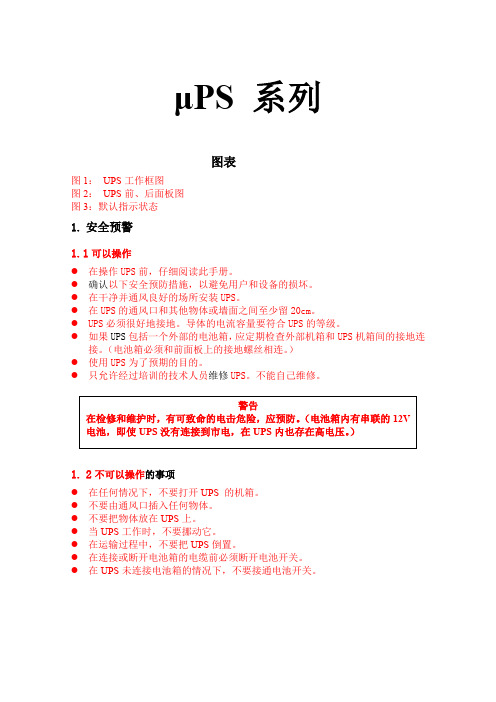
μPS 系列图表图1:UPS工作框图图2:UPS前、后面板图图3:默认指示状态1.安全预警1.1可以操作●在操作UPS前,仔细阅读此手册。
●确认以下安全预防措施,以避免用户和设备的损坏。
●在干净并通风良好的场所安装UPS。
●在UPS的通风口和其他物体或墙面之间至少留20cm。
●UPS必须很好地接地。
导体的电流容量要符合UPS的等级。
●如果UPS包括一个外部的电池箱,应定期检查外部机箱和UPS机箱间的接地连接。
(电池箱必须和前面板上的接地螺丝相连。
)●使用UPS为了预期的目的。
●只允许经过培训的技术人员维修UPS。
不能自己维修。
1.2不可以操作的事项●在任何情况下,不要打开UPS 的机箱。
●不要由通风口插入任何物体。
●不要把物体放在UPS上。
●当UPS工作时,不要挪动它。
●在运输过程中,不要把UPS倒置。
●在连接或断开电池箱的电缆前必须断开电池开关。
●在UPS未连接电池箱的情况下,不要接通电池开关。
2.总体特性up系列三入/单出UPS采用脉宽调制(PWM)和16位微处理器控制技术提供可靠、成熟的保护,可抵御任何的市电电压波动或断电。
图1:UPS的工作框图在市电停电时,UPS可提供一定时间内的备用电源。
正如在图1中所示,这个单元被设计用于和Gamatronic UPS系统并机操作。
负载在各单元之间分配。
对任何重要负载,并机系统是最可靠的电力资源。
如果这个系统使用N+1UPS(冗余并机系统),即使一个单元失败,输出电压也不中断。
如果并机系统装备有另外的静态开关,即使多个UPS故障。
输出电压也不中断。
Gamatronic并机系统包括以下特点:●每个UPS装备有自己的电池。
●最多可并列连接10个并机单元。
本系统对用户友好,操作简便而用户无需懂技术知识。
UPS为在线式,一旦启动,本单元可为任何负载提供110、220、230或240V的50或60Hz的稳定的电源(根据您的要求)。
当备用工作时(市电停电),UPS由电池供电并维持恒定的电压输出。
PowerCube PB6 中文名字说明书

Medium voltage productsPowerCube PB6Pre-assembled modules for buildingmedium voltage switchgear2IndexGeneral characteristics1 4.2 7. Main components310. Types available and apparatus4 12.Overall dimensions and weightsCompletion of the switchgear5 18.341. General characteristicsGeneralPowerCube modules allow medium voltage air-insulatedswitchgear to be constructed with the same rated currents as those of the enclosure.PowerCube modules are pre-assembled and tested in the factory and comply with IEC 62271-100, CEI 17-1, IEC 60298 and CEI 17-6 Standards.They are available with the following characteristics:Rated voltage [kV]36 Rated current[A]... 2500 (*)Rated short-time main circuit withstand current[kA]... 25 x 3s ... 31.5 x 1s(*) 2500 A with forced ventilation.VD4 series circuit-breaker and HD4 series gas circuit-breakers can be installed in the PowerCube PB6 modules.All the operations are carried out from the front of the module.Degrees of protectionThe degrees of protection of PowerCube modules comply with IEC 60529 Standards.The following standard degrees of protection are guaranteed on the front:external housing IP4X inside the unitsIP2XInterlocksThe PowerCube module is fitted with interlocks to prevent incorrect operations which might endanger the personnel in charge of running the installation, as well as the efficiency and reliability of the apparatus.In particular, locking devices to prevent the following operations are provided:– circuit-breaker closing in the intermediate position – racking-out of closed circuit-breaker – racking-in of closed circuit-breaker– circuit-breaker compartment door opening in the connected or intermediate position– circuit-breaker racking-in with compartment door open.And, if the unit is fitted with an earthing switch:– earthing switch closing with the circuit-breaker in the connected or intermediate position– racking-in the circuit-breaker with the earthing switch closed– feeder compartment door opening with the earthing switch open– earthing switch opening with the feeder compartment door open.Note : some of the interlocks listed above are supplied on request.Environmental conditionsThe switchgear ratings are guaranteed under the following ambient conditions:Minimum ambient temperature – 5 °C Maximum ambient temperature + 40 °C Maximum relative humidity 95%Maximum altitude1000 m a.s.l.In an unpolluted and not corrosive atmosphere.512A Circuit-breaker compartment1 Voltage signalling device (on request)2 Circuit-breaker/truck/VT truck3 Metal shutters4 Lower and upper monoblocs5 Earthing switch (on request)6 Door7 Fans (only for 2500 A)8 Lower door6Test laboratoryComplies with ISO 45001 Standards, accredited by an independent external organisation.Health and Safety Management SystemThis complies with the OHSAS 18001 Standards, certified by an independent external organisation.Quality SystemComplies with ISO 9001 Standards, certified by an independent external organisation.Environmental Management SystemComplies with ISO 14001 Standards, certified by an independent external organisation.1. General characteristicsPowerCube Module Without earthing switch With earthing switch PB6PR6PB6PR6Module width [mm]1000100010001000Rated voltage[kV]36363636Test voltage at industrial frequency [kV]70707070Impulse withstand voltage [kV]170170170170Short-time withstand current [kA]25 (3s)25 (3s)25 (3s)25 (3s)[kA]31.5 (1s)31.5 (1s)31.5 (1s)31.5 (1s)Peak current[kA]63636363[kA]79797979Rated currents[A]630630630630[A]1250125012501250[A]1600160016001600[A]2000200020002000[A]2500 (*)2500 (*)2500 (*)2500 (*)Earthing switch making capacity[kA]--2525(*) Forced ventilationElectrical characteristics of PowerCube modules7Circuit-breakersPowerCube modules can be fitted with VD4 serieswithdrawable circuit-breakers or HD4 series SF6 withdrawable circuit-breakers.The circuit-breakers are fitted with a truck which allows them to be racked-in and out in the switchboard with the door closed.A compact and light structure ensures sturdiness and excellent mechanical reliability.The operating mechanism and poles are fixed to the metal structure which also acts as a support for the moving contact actuation kinematics.Series VD4 vacuum circuit-breakersVD4 circuit-breakers use the vacuum as breaking and insulating medium.Thanks to the advanced manufacturing techniques withwhich they are made, vacuum circuit-breakers provide a high performance in all operating conditions.The vacuum interrupters are embedded in poles made of epoxy resin. This construction protects the interrupters from shock, humidity and environmental pollution.The circuit-breaker poles, which form the interrupting part, are life-long sealed pressure devices (Standards IEC 62271-100 and CEI 17.1-1) and are maintenance-free.VD4 circuit-breakers feature a mechanical type of operating device; both operating mechanisms are the trip-free stored energy type with independent opening and closing regardless of the operator’s action.HD4 series SF6 gas circuit-breakerVD4/W 36 kV HD4 series SF6 circuit-breakersThe HD4 series of medium voltage circuit-breakers use sulphur hexafluoride gas (SF6) to extinguish the electric arc and as insulating medium. The breaking principle of HD4 circuit-breakers is based on compression and self-blast techniques to obtain top performance at all service current values, with gradual arc extinction, without any restriking, operating overvoltages and chopped currents. These characteristics guarantee long electrical life for the circuit-breaker and limited dynamic, dielectric and thermal stress on the installation. The circuit-breaker poles, which make up the interruption part, are sealed for life pressure systems (IEC 62271-100 and CEI 17.1 Standards) and are maintenance-free. The stored energy mechanical operating mechanism has free release and allows opening and closing operations independent of the operator.8Earthing switchesThe PowerCube PB6 module can be fitted with an earthing switch.The earthing switch features making capacity on short-circuit. The opening and closing operations can be locked, on request, by means of key locks.Earthing switch operation is carried out from the front of the module with manual operation suitably interlocked with the position of the circuit-breaker.Consult the table on page 11 for the list of accessories”.Earthing switch open.Earthing switch closed.Signalling of the earthing switch position.Signals (open/closed) showing the position of the earthing switch are visible from thefront of the enclosure (if forced ventilation is not provided) or from the operating slot of the earthing switch.Monoblocs and shuttersThe monoblocs consist of insulating branches (fig. A) orterminals (fig. B) containing the power connections - top and bottom - of the circuit-breaker compartment, towards the feeder and busbar compartments respectively.The shutters (fig. C) are the metal type and are activatedautomatically when the circuit-breaker changes from the test/isolated position to the connected position and viceversa.Each shutter can be locked by means of two independent padlocks (optional).Figure A9VT CompartmentPowerCube PR6 module can be configured as VT compartment with withdrawable voltage transformers.The voltage transformers are the dedicated type and are protected by fuses. The fuses can be replaced with theswitchgear in service as the fuse compartment is segregated metallically from the other compartments.Consult the table on page 11 for the list of accessories.Figure B Figure C1023Notes for using PowerCube modules– Use of PowerCube PB6 modules is recommended for constructing incoming, outgoing and bus-tie type switchgear units (see table on following pages.– Use of PowerCube PR6 modules is recommended for constructing bus-riser, measurement and direct busbar incoming switchgear units.1. Monoblocs2. Branches/terminals.3. Fans. Pre-installed in 2500 A PB6 modules.Example of PB6 PowerCube module (front and rear views).Example of PR6 PowerCube modules (front view).3. Types available and apparatusVD4 withdrawable circuit-breakers for PowerCube modules(1) Operation sequence: O - 0.3”-CO-3’-CO.(2) 2500 A with forced ventilation inside PowerCube PB6.(3) Please ask ABB.AccessoriesThe table below indicates the accessories available and the relative combination with the PowerCube modules.PowerCube module PB6PR6 Width [mm]10001000 Rated voltage36 kV••Unit Incoming/outgoing/bus-tie•-Bus-riser/measurements/incoming/direct-•Standard fittings 1a Group of auxiliary contacts connected/isolated•-1b Anti-racking-in lock for circuit-breakers with lower rated currentof the compartment•-Accessories to be specified at the time of ordering (assembly by ABB)2Circuit-breaker anti-racking-in lock•-3VT compartment-•4Earthing switch••5Key locks open or closed or open and closed for earthing switch••6Electrom. lock for earthing switch(24-48-60-110-220 Vdc; 110-220 Vac 50 Hz)••7Earthing switch auxiliary contacts (5 or 10)••8Lower door with handle (only if earthing switch is requested)••Accessories on request (assembly by the customer)9Anti-condensation heater (110-220 Vac 50 Hz)•• (VT truck) only 10Mechanical interlock for circuit-breaker compartment door •• (VT truck) only 11Padlock for metal shutters (top or bottom or top and bottom)•• (VT truck) only 12Earthing switch operating lever - extra in relation to normal supply (*)••13Lifting eyebolts••14Apparatus transport and racking/in truck•• (VT truck) only(*) Remember that the standard supply provides up to 10 levers per order position with a maximum of 1 lever per enclosure (fitted with earthing switch).3. Types available and apparatusPB6 PowerCube module - 630-1250 A - with branchesIndicative weight of the module (without earthing switch) Rated current [A] Weight [kg]630 - 1250400PB6 PowerCube module - 630-1250 A - with terminalsRated current [A] Weight [kg]630 - 1250350PB6 PowerCube module - 1600 - 2500 A - with branchesIndicative weight of the module (without earthing switch) Rated current [A] Weight [kg]630 - 12504502500 5004. Overall dimensions and weights PB6 PowerCube module - 1600 - 2500 A - with terminalsIndicative weight of the module (without earthing switch)Rated current [A] Weight [kg]1600 - 2000 4002500 450PR6 PowerCube module - with branchesIndicative weight of the module (without earthing switch) Rated current [A] Weight [kg]630 - 1250up to 4001600 - 2000 up to 4002500 up to 4004. Overall dimensions and weights PR6 PowerCube module - with terminalsIndicative weight of the module (without earthing switch)Rated current [A] Weight [kg]630 - 1250up to 3501600 - 2000 up to 3502500 up to 350To complete the switchgear, ABB can also offer the components indicated below.For further details, please consult us.Voltage transformersThe voltage transformers are the type insulated in resin andare used to supply measuring and protection devices.The are available for fixed assembly or for installation onwithdrawable trucks.They comply with the IEC 60044-2 Standards.Their dimensions usually conform to the DIN 42600 Standard.The transformers installed on withdrawable trucks are, on theother hand, of the dedicated type.These transformers can have one or two poles, withperformance and precision classes suited to the functionalrequirements of the instruments connected to them.When they are installed on withdrawable trucks, they arefitted with medium voltage protection fuses. The fuses can bereplaced with the switchgear in service.Current transformersThe current transformers are the type insulated in resin andare used to supply measuring and protection devices. Thesetransformers can either have a wound core or a through barwith one or more cores, with performance and precisionclasses suited to the installation requirements.They comply with IEC 60044-1 Standards.Their dimensions usually conform to the DIN 42600 standard.The current transformers can also be fitted with a capacitivesocket for connection to the voltage signalling lamps.REF542plus electronic unitThe REF542plus unit integrates all the secondary functions of a switchgear unit in a single module with watchdog. Thanks to flexible software, the unit can meet a vast range of installation requirements: protection measurement, control and signalling. The user interface is simple and easy to use.REF542plus in a kit for OEMThe integrated protection and control unit is based on the REF542plus platform - multi-purpose unit for medium voltage switchgear.The REF542plus unit uses the latest microelectronic and information technology discoveries.The REF542plus unit provides the following main functions: • protection• control• measurement• monitoring• quality of the energy• communication.Thanks to the exceptional flexibility and scalability of this advanced unit, all the functions are integrated in a single configurable environment.This unit therefore makes targeted and intelligent solutions possible, with limited wiring requirements, in those places where the traditional approach would be costly and inefficient.Industrial ITThis product has been tested and certified as conforming to Industrial IT, Level 0 - Information. All the information about the product is provided in an interactive electronic format, compatible with ABB Aspect Object TM technology.ABB’s commitment to respecting Industrial IT conformity guarantees that each construction unit is provided with all the instruments needed to ensure efficient installation, function and maintenance operations throughout the useful life of the product.For further information about Industrial IT please visit the following site: </industrialit>.Some of the solutions already configured for protection and control of most of the common medium voltage applications are defined here.These solutions are based on the REF542plus unit and do not require any programming.The REF542plus unit is supplied already programmed and ready for installation.Only the protection parameter setting remains to be carried out.The REF542plus unit, already configured, can only be ordered as part of the medium voltage kit.It cannot be sold separately.21Configuration of the primary part is structured as shown in the single-line diagram below.The circuit-breaker can be fixed or withdrawable. The earthing switch is manual. Configurations with a contactor in place of the circuit-breaker are also provided foroutgoing motor feeders.The ATEX certified version, in accordance with directive 94/9/EC for explosive environments, is also available. Please contact ABB.NoteSpecific and customised solutions and protection diagrams are possible. Please contact ABB.Technical reference documentationThe pre-configured REF542plus unit described in thiscatalogue is based on release 1.1 (V4C01 software version).For further information about the REF542plus unit, please ask for the following documentation:• REF542plus Technical Catalogue, 1VTA100001en-H PTMV, 11.2003• REF542plus Manual Part 1: Operation and Maintenance, 1VTA100002en-04 PTMV, 10.02.02.• REF542plus Manual Part 2: Engineering & Technical References, 1VTA100003en-04 PTMV, 10.02.02.• REF542plus Manual Part 3: Installation and Commissioning, 1VTA100004en-04 PTMV, 10.02.02.• REF542plus Manual Part 4: Communication to station control system, 1VTA100005en-01 PTMV, 10.02.02.• REF542plus Technical References Modbus RTU, 1VTA100065-2 PTMV, 10.02.02.• REF542plus Release 1.1 Type Test Certificate 1VTA100022 PTMV, 31.01.02.• REF542plus Connection Diagram 401734, Rev. M3565 7/6/01 ABB.• REF542plus EC Conformity, 1VTA100159 PTMV, 28.08.02.• EC-Type-Examination Certificate (PTB 02 ATEX 3000) PTB September 2002.Single-line diagram of the primary part.Notes 2223ABB S.p.A.Power Products Division Unità Operativa Sace-MV Via Friuli, 4I-24044 DalmineTel.: +39 035 6952 111Fax: +39 035 6952 874E-mail:**************.comThe data and illustrations are not binding. We reserve the right to make changes without notice in the course of technical development of the product.© Copyright 2013 ABB. All rights reserved.Contact us1V C D 000178 - R e v . F , e n - T e c h n i c a l C a t a l o g u e - 2013.01 (P o w e r C u b e P B 6) (g s )。
power变频器说明书

power变频器说明书Power变频器说明书第一章:引言1.1 背景介绍Power变频器是一种用于调节电力设备输出频率的装置。
它可以将输入电源的直流电转换成交流电,并通过调整输出频率来控制电机的转速。
本说明书将详细介绍Power变频器的使用方法和技术参数,帮助用户正确使用和维护该设备。
第二章:技术原理2.1 变频器的工作原理Power变频器通过将输入电源的直流电转换为高频交流电,然后通过PWM技术将高频交流电转变为输出频率可调的交流电。
其核心部件是IGBT模块,通过对IGBT的控制,可以实现对输出电压和频率的精确控制。
第三章:产品特点3.1 高效节能Power变频器采用先进的控制算法和优化设计,能够实现高效能耗,并通过降低电机的负载损耗来节约能源。
3.2 安全可靠Power变频器具有过电压、过电流、过载、短路等多种保护功能,能够保证设备和电机的安全运行。
同时,它还具备故障自诊断和报警功能,可以及时发现并解决问题。
3.3 灵活调节Power变频器可以根据实际需要调节输出频率和电压,以满足不同工况下电机的要求。
通过对参数的调整,用户可以实现精确的速度调节和电机控制。
3.4 易于安装和维护Power变频器采用模块化设计,结构紧凑,安装方便。
同时,具备自动故障检测和报警功能,便于用户进行维护和保养。
第四章:使用方法4.1 连接电源和电机用户在使用Power变频器前,需要先将其与电源和电机进行连接。
根据接线图,正确连接各个端口,并确保接触良好,以避免电路异常和故障。
4.2 参数设置在开始使用前,用户需要根据实际需求设置Power变频器的参数。
包括输入电压、输出频率、电机转速等,用户可以根据设备的使用要求进行调整。
4.3 启动和停止启动Power变频器前,用户需要先将控制面板上的开关拨到“ON”位置,并按照启动顺序进行操作。
停止时,需按照反序进行操作,并将开关拨到“OFF”位置。
4.4 故障排除如果在使用过程中出现故障,用户可以查看设备的故障代码和报警信息,并参照说明书中的故障排除方法进行处理。
CUBE简体说明书
中文简体使用手册亲爱的用户:非常感谢您选购这款CUBE产品。
我们衷心希望您能从中获得长久的享受。
祝愿您从该产品中获得最好的多媒体体验!本手册中包含的所有信息在出版时都是正确的。
但是,由于我们不断对产品进行更新和改进,因此在您设备上的软件,在外观和功能上可能与本手册中所描述的内容略有差别。
目录注意事项 (3)1. CUBE 基本功能 (4)1.1 CUBE 硬件配置----------------------------------------------------------------- 41.2 CUBE 软件配置----------------------------------------------------------------- 42. CUBE 设备描述 (5)2.1 触摸屏-------------------------------------------------------------------------- 52.2 Camera -------------------------------------------------------------------------- 52.3 Home键------------------------------------------------------------------------- 52.4 充电指示灯---------------------------------------------------------------------- 52.5 Menu键------------------------------------------------------------------------- 62.6 Back键--------------------------------------------------------------------------- 62.7 Mic孔---------------------------------------------------------------------------- 62.8 T-Flash卡------------------------------------------------------------------------ 62.9 Mini USB ------------------------------------------------------------------------- 62.10 电源拨钮----------------------------------------------------------------------- 62.11 Earjack -------------------------------------------------------------------------- 62.12 DC ------------------------------------------------------------------------------ 63. 首次使用CUBE (7)3.1 电池管理及充电------------------------------------------------------------------ 73.2 打开/关闭MID设备-------------------------------------------------------------- 73.3 与PC连接------------------------------------------------------------------------ 84. CUBE 设备基本操作 (8)4.1 主界面描述----------------------------------------------------------------------- 84.2 菜单界面描述-------------------------------------------------------------------- 104.3 状态栏描述---------------------------------------------------------------------- 104.4 使用触摸屏---------------------------------------------------------------------- 115. CUBE 设备基本设置 (12)5.1 无线控制------------------------------------------------------------------------ 125.2 声音和显示---------------------------------------------------------------------- 145.3 安全性和位置-------------------------------------------------------------------- 155.4 应用程序------------------------------------------------------------------------- 1615.5 SD卡和MID存储------------------------------------------------------------------ 165.6 日期和时间----------------------------------------------------------------------- 175.7 区域和文本----------------------------------------------------------------------- 175.8 触摸屏校准----------------------------------------------------------------------- 185.9 USB模式选择--------------------------------------------------------------------- 185.10 关于MID ------------------------------------------------------------------------ 186. CUBE 软件安装及管理 (19)6.1 APK安装器----------------------------------------------------------------------- 196.2 ES文件浏览器-------------------------------------------------------------------- 216.3 ES任务管理器-------------------------------------------------------------------- 226.4 应用市场------------------------------------------------------------------------ 237. CUBE 软件应用与操作 (23)7.1 图片浏览------------------------------------------------------------------------ 237.2 音乐播放------------------------------------------------------------------------ 257.3 视频播放------------------------------------------------------------------------ 277.4 电子书-------------------------------------------------------------------------- 287.5 将图片/音乐/视频等文件传输到CUBE 设备------------------------------------ 297.6 优酷----------------------------------------------------------------------------- 297.7 网络浏览器---------------------------------------------------------------------- 307.8 电子邮件------------------------------------------------------------------------ 317.9 网络聊天------------------------------------------------------------------------ 327.10 Google Map ------------------------------------------------------------------- 337.11 日历--------------------------------------------------------------------------- 347.12 计算器------------------------------------------------------------------------- 347.13 闹钟时钟----------------------------------------------------------------------- 347.14 天气预报----------------------------------------------------------------------- 358. CUBE 疑难解答 (35)2注意事项本手册包含重要的安全措施和正确使用产品的信息,以避免事故发生,确信在使用该产品之前仔细阅读该手册。
Power Highlight 参考手册说明书

12目录软件概述 ................................................................................................................................................. 1 时标网络图 .............................................................................................................................................. 1 项目列表 ................................................................................................................................................. 4 工作分解结构(WBS ) .......................................................................................................................... 4 作业表格和横道图 ................................................................................................................................... 4 定义日历 ................................................................................................................................................. 5 关键指标 ................................................................................................................................................. 6 责任分配 ................................................................................................................................................. 6 进展反馈责任人 ...................................................................................................................................... 7 赢得值分析 .............................................................................................................................................. 7 形象进度图 .............................................................................................................................................. 8 目标计划 ................................................................................................................................................. 8 过滤器 ..................................................................................................................................................... 9 视图 ......................................................................................................................................................... 9 作业模板 ................................................................................................................................................. 9 软件使用许可 ........................................................................................................................................ 10 在线帮助 ............................................................................................................................................... 10 进展反馈(Power Reporter ) .. (11)上海普华科技发展股份有限公司1软件概述时标网络图Power Highlight 软件主要用于项目进度计划的编制和展示。
POWERTECH高频智能充电器说明书
High Frequency Intellicharger™
An
Company
POWERTECH™
What is a ‘High Frequency Intellicharger™’ and how does it save me money?
POWERTECH™ is a high frequency smart charger. POWERTECH™ assesses each battery’s charging requirements through its patented intelligent technology. POWERTECH™ is designed to save you money on utilities, watering, and battery life.
200
50
180 48
160
140
CHARGING CURRENT120Fra bibliotek100
80
60
46
44 VOLTAGE
42
40
40
20
0
38
0
11
2
3
4
5
6
7
TIME
Charge Profile: POWERTECH™ PT3-18-200Y are on an 1020 AH 36-VOLT battery (80% DOD).
• Universal Use – POWERTECH™ dynamically assesses each battery’s charging requirements, which means that one POWERTECH™ charger can recharge batteries from 450 up to 1600 AH without adjustment - as long as they are the same voltage. So, you can recharge any 36-volt battery on any POWERTECH™ 36-volt charger. Should your operation change trucks or move from standard to high-energy batteries, there is no need to purchase new chargers - your POWERTECH™ charger will adjust automatically. And POWERTECH™ can be set for flooded or gel batteries.
PowerCube PB 系列中文名字说明书
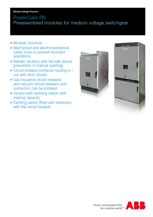
• Modular structure• Mechanical and electromechanicalsafety locks to prevent incorrect operations• Metallic shutters with fail safe device (prevention of manual opening)• Circuit-breaker/contactor racking in / out with door closed• Gas insulated circuit-breakersand vacuum circuit-breakers and contactors can be installed• Version with earthing switch with making capacity• Earthing switch fitted with interlocks with the circuit-breaker2PowerCube PB6A12PowerCube PB/M PB/M PB/M PB/M Rated voltage[kV]1217.52436 Rated insulation voltage [kV]1217.52436Withstand voltage (50 Hz) [kV]28385070 Impulse withstand voltage [kV]7595125170Rated frequency[Hz]50-6050-6050-6050-60Rated normal current (40 °C)[A]630630630630125012501250125016001600160016002000200020002000250025002500 (1)2500 (1)31503150--3600 (1)3600 (1)--4000 (1)4000 (1)--Rated short-time withstand current (3 s)[kA]25-31.5-40-50 (2)25-31.5-40-50 (2)25-31.5 25 (3s)-31.5 (1s)Overall dimensions (excluding monoblocs)H [mm]1680168016802034W [mm]600/750/1000600/750/1000750/10001000D [mm]103010301030920Weight[Kg]120450320ask ABB Degree of protectionIP 3XIP 3XIP 3XIP 3XCompatible circuit-breakers and contactors– HD4••••– VD4•••-– V-Contact (module width 600 mm)•---Technical catalogueNo.1VCP0000911VCP0000911VCP0000911VCP000178(1) With forced ventilation using fan built into the enclosure (for 4000 A another fan must be installed in the rear part of the switchgear), (2) 25-31.5 kA for PowerCube module width 600 mm.Technical data PB/MMain componentsA Circuit-breaker compartment1 Voltage signalling device (on request)2 Circuit-breaker/contactor3 Shutters4 Lower and upper monoblocks5 Earthing switch (on request)6 Door7 FanB Feeder cable compartment 8 VT compartment (on request)9 DoorH W D3A Circuit-breaker compartment1 Voltage signalling device (on request)2 Circuit-breaker/contactor3 Shutters4 Lower and upper monoblocks5 Earthing switch (on request)6 Door7 FanPowerCube PB/E PB/E PB/E Rated voltage[kV]1217.524Rated insulation voltage [kV]1217.524Withstand voltage (50 Hz) [kV]283850Impulse withstand voltage [kV]7595125Rated frequency[Hz]50-6050-6050-60Rated normal current (40 °C)[A]630630630125012501250160016001600200020002000250025002500 (1)31503150-3600 (1)3600 (1)-4000 (1)4000 (1)-Rated short-time withstand current (3 s)[kA]25-31.5-40-50 (2)25-31.5-40-50 (2)25-31.5 Overall dimensions (excluding monoblocs)H [mm]112011201230W [mm]600/750/1000600/750/1000750/1000D [mm]1016/10301016/10301246Weight[Kg]120450320Degree of protectionIP 3XIP 3XIP 3XCompatible circuit-breakers and contactors– HD4•••– VD4•••– V-Contact (module width 600 mm)•--Technical catalogueNo.1VCP0000911VCP0000911VCP000091Technical data PB/E(1) With forced ventilation using fan built into the enclosure (for 4000 A another fan must be installed in the rear part of the switchgear). (2) 25-31.5 kA for PowerCube module width 600 mm.Main componentsHWD1V C P 000092 - R e v . G , e n - L e a f l e t - 2009-02 - (P o w e r C u b e )For more information please contact:ABB S.p.A.Power Products Division Unità Operativa Sace-MV Via Friuli, 4I-24044 DalmineTel.: +39 035 6952 111Fax: +39 035 6952 874E-mail:*******************.comABB AGCalor Emag Medium Voltage ProductsOberhausener Strasse 33 Petzower Strasse 8 D-40472 Ratingen D-14542 Glindow Phone: +49(0)2102/12-1230, Fax: +49(0)2102/12-1916 E-mail:*****************.com The data and illustrations are not binding. We reserve the right to make changes without notice in the course of technical development of the product.Copyright 2009 ABB.All rights reserved.。
G.T.POWERA6中文说明书(有图版)

G.T.POWER A6 中文说明书感谢您选购此款充电器.您选购的这款是运用高科技和专业操控软件的快速充电/放电器. 在使用此产品之前请认真阅读完此操作手册.特征最佳操作软件当充/放电时,它具有自动设定电流的功能.尤其是锂电池,可以防止因用户失误而造成的充电爆炸事故. 单位内的每个程序,都是相互控制与联系,使每一个可能的误差为最高安全.这些可以根据用户的选择来设定.接受,转接,启动充电器的特殊充电插口.频繁使用的充电器插口,比如多功能插头等. 此软件也为锂电池提供最方便的平衡充电插口.分别是3,4,5,6,7,8充电插口和外部接转连接器.高功率和高性能的电路它所使用的电路最大输出功率为50瓦特.因此,当最大电流是5.0安时,它充电或者放电可以达到15个NiCd/NiMH和8节锂电池并联的效果.此外,制冷系统可以在这样的功率下毫无障碍地运行CPU或操作程序.锂电池内部的单个电压平衡器它里面带有独特锂电池专用的平衡功能.因此在充锂电(Lilo/LiPo/LiFe)时,不需要额外的平衡器来平衡电压.平衡放电的单个电池它在放电时,还可以监测和平衡锂电池组中的单个电池.当电池电压出现异常时,放电就会伴随错误信息而停止.适合各种各样的锂电池它可以接受三种类型的锂电池- Lilo, LiPo 和 LiFe.它们因化学成分的不同而具有不同的特点.你可以选择他们中任一一种来使用,根据它们的规格,参照”警告和安全说明书”.锂电池快速和存储模式你可以充电锂电池作特殊用途。
快速充电减少了锂电池的充电时间,而存储模式也使得锂电池的额定电压可以长时间的储存.最大化安全Delta-peak sensitivity:一种自动充电电流关闭程序,其工作原理是在电池电压上升至最高点而开始回降时,将充电电流关闭完成充电.(镍镉/镍氢)自动充电电流限制:在自动电流模式下充镍镉或镍氢电池,你可以设置充电电流的上限以避免高充电电流.在’AUTO’模式下,在充低阻碍,小容量的镍氢电池时非常有用.容量限制:充电容量以充电电流×充电时间来计算.在设定了最高充电值的情况下,当充电容量超过了最高限额时,程序将强制结束充电.温度限制:充电时,电池由于内部发生化学反应,温度也将相应增高.如果对充电器设定温度限制,在温度到达最高限额时,程序将强制结束充电.充电时间限制:对充电时间进行限制也可以防止任何可能的错误.输入电流检测器:为保护蓄电池在电流输入时不受损坏,通常可以对其电压进行检测.当电压下降至最低额时,程序将自动关闭充电电流.自动制冷风扇:只有在单个电池的内部温度升高时,电子制冷风扇才自动运转.资料存储/下载为方便用户,它最多可以存储5个数据不同的电池.你可以建立包含了程序设置的数据来持续不断的充电或是放电.在你需要的任意时候都可以叫出这些数据,并且这个过程在没有设定程序时执行.循环充电或者放电持续不断的运转1-5周期使电池得以更新和平衡.个人计算机为基础分析应用的USB通信它为技术专家提供了以个人计算机为基础,可分析电池USB接口的特性.它表明了一个稳定的电压,电流,容量和温度曲线.它也可以显示锂电池组中每一个电池的电压.充电器外观警告和安全提示○任何情况都不要在无人看管的情况下充电.如果有故障出现,请立即结束程序,再查阅程序说明书.○不要放在有灰尘,潮湿,太阳直射或振动的地方,不要摔它.○进入电源只允许10-18DC电源.○充电器和电池在充电或放电时应放置在强抵抗,防易燃和抗导体的表面上.切勿放在汽车坐垫上,地毯上或类似物体上.确保所有易然易爆物品远离操纵区域.○充电器的冷却口不能被覆盖或关闭,以便提供良好的通风.确保准确地掌握要充电和放电的电池性能.如果程序设置错误可能损坏电池.尤其是锂电池,可能会导致火灾或充电过度导致爆炸.NiCd/NiMH 电压等级: 1.2v/cell允许快速充电电流: 1C~2C依赖于电池的运转. 放电电压切断级别:0.85v /cell(镍镉电池), 1.0v/cell (镍氢电池)Lilo 电压等级:3.6V/c最大充电电压: 4.1V/cell允许快速充电电流: 1C或更少最小放电电压切断级别:2.5V/cell或更高LiPo 电压等级:3.7V/cell最大充电电压: 4.2V/cell允许快速充电电流: 1C或更少放电电压切断级别:3.0V/cell或更高LiFe 电压等级:3.3V/cell最大充电电压:3.6 V/cell允许快速充电电流: 4C或更少(例如A123M1)放电电压切断级别:2.0V/cell或更高Pb 电压等级:2.0V/cell(Lead-acid) 最大充电电压: 2.46V/cell允许快速充电电流: 0.4C或更少放电电压切断级别:1.50V/cell或更高○为避免充电导线之间发生短路,应先将充电导线与充电器连接, 然后再连接电池,拆-你必须注意核实锂电池组的容量和电压.它可能是串,并联混合组成.并联时,电池组的容量是每个电池的容量乘以电池的个数,而电池组的电压不变. 在充电过程中,这种电压不平衡引起火灾或爆炸,我们建议你串联锂电池组.○放电放电的典型目的是确定电池剩余的容量或是降低电池的电压来界定级别.当你给电池放电时,必须和充电时一样注意放电过程.为了避免电池放电过度,一定要正确设定额定放电电压.锂电池不能低于最低电压,因为这样会导致容量的快速损失或者完全失败.一般来说,不需要给锂电池放电.-据说一些充电电池有记忆效应。
(word完整版)德国布朗卢比PowerMon 中文操作手册

PowerMon OERATION MANUALKOLORIMETERSILIKOMETERIONOMETERNATRIOMETERTITROMETER在安装或开始运行系统时,请仔细阅读本手册。
Bran+Luebbe公司不对由不遵守说明书而造成的损坏负责,并且质保期也会随之失效.使用非Bran+Luebbe原装的配件也会导致质保期的失效。
本说明书中的内容可以由Bran+Luebbe公司单方面更改而无需另行通知。
未经Bran+Luebbe公司的书面许可,本手册的任何部分都不允许以任何方式——电子地或机械地——被复制,传播.即便本手册被译为多种语言的版本,德文的版本为原始版本.目录1 介绍 (4)1.1 本手册的惯例 (4)2 安全建议 (5)3 运行操作 (6)3.1 概述 (6)3.2 触摸屏 (6)3.2.1 初始化 (7)3.2.2 PowerMon 的结构和布局 (8)3.3 结果 (8)3.3.1 表格 (9)3.3.2 图表 (10)3.3.3 信息 (10)3.4菜单 (11)3.4.1 系统 (11)3.4.2 传感器列表 (12)3.4.3 参数列表 (17)3.4.4应用 (17)3.4.5 服务 (23)3.4.6 帮助 (34)3.5 操作模式 (35)3.5.1 测量模式 (36)3.5.2 校准模式 (36)3.5.3 停止模式 (36)3.5.4 错误模式 (37)4 报错信息 (38)4.1 概述 (38)4.2 报错信息概述 (38)1 介绍Bran+Luebbe公司的PowerMon系列分析仪表是新一代完全自动化的在线分析仪表的。
他们用湿化学的方法,可以连续不断地测量液体样品中的多种成分的浓度。
本手册说明了以下两种分析仪表:· POWERMON KOLORIMETER·POWERMON SILIKOMETER·POWERMON LONOMETER·POWERMON NATRIOMETER·POWERMON TITROMETER操作人员需要有一定的基础技术知识.在安装调试前请仔细阅读本手册.将手册一直放在系统的附近,以方便查阅。
Pulse VS-series 出力功率放大器操作手册说明书

| VS Series User ManualVS SERIESRackmount 100V slave amplifiersVS120, VS240, VS360Caution: Please read this manual carefully before operatingDamage caused by misuse is not covered by the warrantyIntroductionThank you for choosing the Pulse VS-series rackmount 100V slave amplifier as part of your public address system. This amplifier is designed to offer high quality, dependable service for mobile and installed systems. Please read this manual fully and follow the instructions to achieve the best results with your new purchase and to avoid damage through misuse.To prevent the risk of fire or electric shock, do not expose any components to rain or moisture.If liquids are spilled on the casing, stop using immediately, allow unit to dry out and have checked by qualified personnel before further use. Avoid impact, extreme pressure or heavy vibration to the case No user serviceable parts inside – Do not open the case – refer all servicing to qualified service personnel.Safety• Check for correct mains voltage and condition of IEC lead before connecting to power outlet • Use double insulated speaker wire with adequate current rating for 100V speaker connections • Do not use 8Ω and 100V terminals at the same time•Do not allow any foreign objects to enter the case or through the ventilation grillesPlacement• Keep out of direct sunlight and away from heat sources • Keep away from damp or dusty environments• For rack-mounting, ensure adequate support for the weight of the amplifier• Ensure adequate air-flow and do not cover cooling vents at the front and rear of the amplifier • Ensure adequate access to controls and connectionsCleaning• Use a soft cloth with a neutral detergent to clean the casing as required•Use a vacuum cleaner to clear ventilation grilles of any dust or debris build-ups • Do not use strong solvents for cleaning the unitFront panel1. MASTER volume control2. POWER, SIGNAL, PEAK LED indicators3.Power switchConnection and setupConnect the rear IEC inlet (6) to the mains using the supplied mains lead (or an equivalent approved type). Ensure that the voltage is correct as indicated on the voltage selector (5) and that the mains outlet is switched on.Alternatively, the VS120 and VS240 can be powered by a 24V battery, such as a lorry or boat battery, by connecting the “+” and “-” of the battery to the 24Vdc INPUT (7) on the rear panel. Ensure that DC cables are capable of handling the current (10A min. recommended)The VS series amplifiers are intended to be fed from a mixer or mixer-amplifier signal output, providing additional power amplification for 100V speaker systems. The signal input should be connected to the SLAVE IN dual RCA connectors (12) on the rear panel. The VS series slave amplifiers are mono, so any stereo input signals will be summed together to provide a monaural output. Further slave amplifiers can be connected from the rear SLAVE OUT RCA sockets (11), allowing banks of amplifiers to operate together in large public address systems.Speaker outputsThe VS series slave amplifiers can be used either as 100V line amplifiers or standard low impedance power amplifiers. These 2 configurations cannot be used together, so it is important to decide which method will be used at the start.4. Ventilation grille - do not cover5. Mains voltage selector switch6. IEC mains inlet & fuse holder7. 24Vdc power connection (not VS360) 8. COM speaker terminal 9. 8Ω speaker terminal 10. 100V speaker terminal11. SLAVE OUT connectors (RCA) 12.SLAVE IN connectors (RCA)100V line systemsFor 100V line systems, connect the amplifier to the first speaker in the system using double-insulated speaker wire, which has adequate current rating to handle the total output of the amplifier.Connect the “100V” (10) output terminal to the positive (+) connection of the speaker and “COM” output (8) to the negative (-) connection of the speaker. Connect further speakers in parallel to the first speaker with all positive terminals and connected together and all negative terminals connected together as shown below.A 100V line speaker system can comprise of many speakers connected together. The determining factor for how many speakers can be used on a single amplifier is the power rating. For most purposes, it is advised to connect as many speakers as needed with a combined wattage of no more than 90% of the amplifier’s output power rating.The terminals of a 100V speaker are connected to a transformer and in some cases, this transformer may be “tapped” for different power ratings. These tappings can be used to adjust the wattage (and output volume) of each speaker in the system to help achieve the ideal total power of the system for the amplifier.Low impedance systemsThe VS series slave amplifiers can provide an output for a single 8Ω speaker by connecting the “8Ω” output (9) to the positive (+) speaker connection and “COM” output (8) to the negative (-) speaker connection. It is important to ensure that the speaker load is no less than 8Ω and that the power handling of the speaker is equal to or greater than the output power of the amplifier.OperationWhen all connections to the amplifier are made, turn the MASTER volume control (1) fully down and switch on the power (3) and the power LED will illuminate. Ensuring that the signal is active on the SLAVE IN inputs, turn up the MASTER gradually to the maximum required volume level.The output of the amplifier is represented on the SIGNAL LED and when the amplifier is running at its peak output, a PEAK LED will illuminate. Care should be taken that the Red PEAK LED is only lit momentarily during use. Anything longer than a short flash of this LED may be indicating distortion or clipping of the output signal and the MASTER volume should be turned down.SpecificationsVS120 VS240 VS360 Power supply 110/230Vac, 50/60Hz (IEC) DC power24Vdc screw terminals 24Vdc screw terminals N/AOutput power: RMS 120Wrms 240Wrms 360WrmsOutput: Line RCA slave out Input RCA slave in Controls Master volume THD<1.0%Dimensions 433 x 363 x 89mm 433 x 363 x 89mm 433 x 403 x 89mm Weight8.88kg 10.06kg11.60kgTroubleshootingEnsure IEC lead is in good condition and connected properlyIf 24Vdc power input is being used, check battery is chargedNo power LED on control panel Ensure POWER switch is on and check mains inlet fuseCheck input signals and condition of input connection leads Power LED is on but no other LEDs and no output Check MASTER volume control is turned upCheck speaker output terminals are connected correctly POWER and SIGNAL LEDs lighting but no output Check speakers are working (test on another amp if available)Check level of input signal is not too highOutput is very loud or distortedReduce MASTER volume levelCheck SLAVE IN signal level is not too lowIncrease MASTER volume level Check for quiet recording of media files on USBOutput is working but at very low level Check VOX override is not unintentionally suppressing audio playback Ensure cooling vents are clear from debris and dustCheck that 4Ω or 8Ω speakers are not connected to 100V terminalsEnsure total 100V speaker wattage is lower than amplifier ratingEnsure that 100V and 8Ω speakers are not both connectedAmplifier overheating Ensure that total load connected to 8Ω output is not less than 8ΩDisposal: The “Crossed Wheelie Bin” symbol on the product means that the product is classed as Electrical orElectronic equipment and should not be disposed with other household or commercial waste at the end of its useful life.The goods must be disposed of according to your local council guidelines.Errors and omissions excepted.Copyright© 2014. Pulse。
PowerEgg X 防水配件快速使用说明说明书

Waterproof Accessory Quick Start Guide EN防水配件快速使用说明AP03防水アクセサリーご使用上の注意事項Guide de démarrage rapide pour accessoires étanches Kurzanleitung Wasserdichtes Zubehör Guida rapida agli accessori impermeabili Guía rápida de inicio - accesorio impermeable CNJPFRDEITES PowerEgg TMX V1.0After the aircraft starts, the metal heat sinks at the tail of the waterproof case will heat up. Do not touchthem.• Troubleshooting1. Foggy lensAs the aircraft is completely sealed after the waterproof case is installed, it will lead to fog inside the waterproof case if the aircraft flies in a humid environment.2. Solutions(1) Before installing the waterproof case, use a piece of dry, soft cloth to clean water drops inside the case.(2) Before installing the waterproof case, apply goggle anti-fogging agents to the inner surface of the case. Refer to the anti-fogging agent instructions for use.• Take off from and land on water1. When taking off from wavy water, the aircraft should rise rapidly from the water surface to prevent it from being affected by the waves.2. When landing on water, the aircraft should descend vertically straight to the surface. If the aircraft’s horizontal speed is too high when landing on water, the aircraft may tip over and float upside down on the water. If the aircraft is upside down, it will automatically shut the motors down and cannot take off again.3. When the aircraft floats on choppy water, it may be prompted that the conditions are not suitable for takeoff. In this case, retrieve the aircraft as soon as possible.4. Do not throw the aircraft into water as it may tip over and then cannot take off.5. If the waterproof case comes into contact with water for a long time, the aircraft may not be able to hover steadily, or it may become difficult to control. In this case, land the aircraft as soon as possible and wipe it dry.6. The control distance of the remote controller depends on the distance between the remote controller and the aircraft above the water. The higher the remote controller above the water, the longer the distance of control and image transmission.7. When the aircraft lands on water, the image transmission control link will be affected, especially when there are waves; therefore, do not land the aircraft more than 100 meters away from the remote controller.• Take off from and land on a boat1. Do not calibrate the aircraft on a rocking or moving boat.2. Taking off from a boat requires plenty of space; if not available, take off instead from open water or ground.3. The aircraft may not unlock if the boat is rocking.Aircraft headThe content is subject to change without notice. View the latest version from www.powervision.mePowerEgg and PowerVision are Trademarks owned by Powervision Tech Inc. Copyright@ PowerVision All Rights Reserved.(包括但不限于沙尘、擦干。
PowerCube高频中文说明书
¾ 当安全性能降低时就可能产生危险,设备必须要送修,包括不能正 常的使用。当出现下列情形时安全性能将不再保证: 外观出现明显的缺陷 设备不能正常工作 设备在恶劣条件下存储过长的时间 设备在运输过程中受到过重的压力 设备内进入液体
制特定形状的感应加热线圈。
第8页
2.3 系统组成 2.3.1 Power Cube 32/45 高频电源 Power Cube 32/900 和 45/900 型高频电源,主要由电源电路、高频发 生装置电路和控制电路三大部分组成。设备通过微处理器,进行系 统自检,并实时监控运行状态、信号显示及必要的中断操作。
一,由高级固态发生装置组成的核心部件,在微型处理器的完全控
制下,向两个即使在狭小空间也同样可以工作的小型感应头提供加
热能量。其独具特色的能量转换方式,确保设备消耗最小的能量,
快速地加热金属物件。
Power Cube 高频电源的设计方案,符合当前国际电气安全标准、
EMC 和 CE 规定。
Power Cube 高频电源最基本的感应加热焊接组成方案包括:
2.3.2 Power Cube 64 高频电源 Power Cube 64/900 型高频电源由两大电气单元组成:
第9页
¾ MAIN UNIT, 用于程序控制 及管理的主单元
¾ SLAVE UNIT,起支持作用的 辅助单元
其构造主要由电源电路、高频发生装 置电路和控制电路三大部分组成。设 备通过微处理器,进行系统自检,并实时监控运行状态、信号显示 及必要的中断操作。 2.3.3 加热头 Power Cube 高频电源,允许连接不同型号的加热头,用于不同工位 的加热焊接:
- 1、下载文档前请自行甄别文档内容的完整性,平台不提供额外的编辑、内容补充、找答案等附加服务。
- 2、"仅部分预览"的文档,不可在线预览部分如存在完整性等问题,可反馈申请退款(可完整预览的文档不适用该条件!)。
- 3、如文档侵犯您的权益,请联系客服反馈,我们会尽快为您处理(人工客服工作时间:9:00-18:30)。
¾ 当安全性能降低时就可能产生危险,设备必须要送修,包括不能正 常的使用。当出现下列情形时安全性能将不再保证: 外观出现明显的缺陷 设备不能正常工作 设备在恶劣条件下存储过长的时间 设备在运输过程中受到过重的压力 设备内进入液体
第3页
5.2 更换组件………………………………………………………第 33 页 5.3 故障分析………………………………………………………第 35 页 6. 附录…………………………………………………….…………第 36 页 6.1 CE 认证资格……………………………………………….…第 36 页 6.2 感应线圈……………………………………………….……第 36 页 6.3 辅助工装………………………………………………..……第 39 页 6.4 防氧化气体工装………………………………….…………第 40 页 6.5 RS232 串口控制……………………………………..………第 41 页
近感应器的金属部分都要接地。 ¾ 仔细选择安装位置,避免安装在阳光下或靠近热源,另外,避免放
到震动、灰尘、潮气、雨雪、过热或过冷的环境中。 ¾ 在安装,使用和维修设备的过程中避免使用暴力。 ¾ 在安装完成后,设备必须稳固,不能左右和上下活动,所有的线缆
必须捆扎牢靠,避免碰撞或以外的损坏确保设备的最佳性能。 ¾ 操作人员必须很容易接近操作设备,不能有任何人身伤害的危险。 ¾ 设备含有电子和电气部件,有产生火灾的可能,不要安装在有爆炸
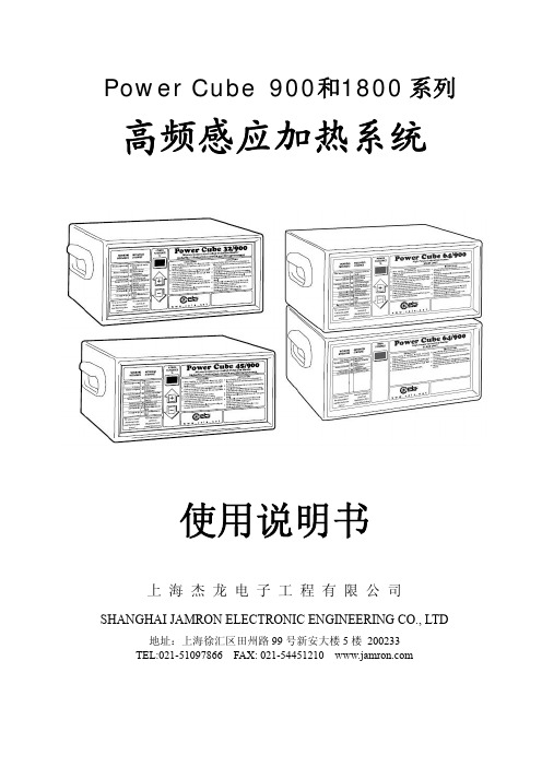
PowerCube32/900 适用工业生产线
PowerCube32/900 适用特殊结构生产线
PowerCube32/1800 适用特殊结构生产线
Power Cube 900和1800 系列
高频感应加热系统
使用说明书
上海杰龙电子工程有限公司
SHANGHAI JAMRON ELECTRONIC ENGINEERING CO., LTD
地址:上海徐汇区田州路 99 号新安大楼 5 楼 200233 TEL:021-51097866 FAX: 021-54451210
Cube 32/1800 型和 Power Cube 45/900 型高频电源) 加热头①的外壳,是用耐高温和抗挤压的塑料材料加工而成,焊有 感应线圈③的金属感应头②,从加热头的前面伸出来,用于产生电 磁场,感应头的上面装有发光二极管④,用于显示加热时的状态, 加热头的后面,是连接至高频电源的电缆线⑤和两个循环冷却水的
¾ HH10 型加热头,适用于 Power Cube 32/900 型和 Power Cube 45/900 型高频电源
¾ HH10 型加热头,适用于 Power Cube 32/1800 型高频电源(仅 适用于特殊结构的生产线)
¾ HH11 型加热头,适用于 Power Cube 64/900 型高频电源 ¾ HH15 微型加热头,(仅适用于 Power Cube 32/900 型、Power
授权的专业技术部门处理。 ¾ 任何故障部件只能由专门设计的零件更换。 ¾ 这非常重要,尽可能的避免开盖和带电维护或维修。如果有必要此
工作只由具有知道所带来危险性的人员来完成。 ¾ 在断开电源后电容仍然处于放电状态,等待 5 分钟后方可修理设备
第7页
2.1 简介
2.概 述
Power Cube 高频电源是专业用于非接触式金属焊接的系列设备之
/satisfaction.asp E-mail: service@
第2页
目录
1. 安全使用须知………………………………………….……………第 5 页 2. 概述……………………………………………….…………………第 8 页
2.1 简介……………………………………………..…….…………第 8 页 2.2 功能结构………………………………….…..…………………第 8 页 2.3 系统组成………………………………….…..…………………第 9 页 2.4 系统防护…………………………………………………..……第 14 页 2.5 系统选项…………………………………………..……………第 14 页 2.6 系统配件………………………………………...………………第 14 页 2.7 系统备件………………………………………..………………第 16 页 2.8 技术指标…………………………………………..……………第 17 页 3. 安装…………………………………………………………………第 19 页 3.1 机械安装……………………………………………….………第 19 页 3.2 冷却水安装………………………………………….…………第 20 页 3.3 电气安装……………………………………………….………第 23 页 4. 使用………………………………………………….………..……第 29 页 4.1 信号显示………………………………………………………第 29 页 4.2 控制方式………………………………………………………第 30 页 4.3 设备应用………………………………………………………第 30 页 4.4 参数设置………………………………………………………第 32 页 5. 维护与保养………………………………………………..………第 33 页 5.1 定期维护………………………………………………………第 33 页
2.3.2 Power Cube 64 高频电源 Power Cube 64/900 型高频电源由两大电气单元组成:
第9页
¾ MAIN UNIT, 用于程序控制 及管理的主单元
¾ SLAVE UNIT,起支持作用的 辅助单元
其构造主要由电源电路、高频发生装 置电路和控制电路三大部分组成。设 备通过微处理器,进行系统自检,并实时监控运行状态、信号显示 及必要的中断操作。 2.3.3 加热头 Power Cube 高频电源,允许连接不同型号的加热头,用于不同工位 的加热焊接:
制特定形状的感应加热线圈。
第8页
2.3 系统组成 2.3.1 Power Cube 32/45 高频电源 Power Cube 32/900 和 45/900 型高频电源,主要由电源电路、高频发 生装置电路和控制电路三大部分组成。设备通过微处理器,进行系 统自检,并实时监控运行状态、信号显示及必要的中断操作。
¾ 在加热时不要让四肢或身体别的部分,红热的金属靠近加热线圈。 不允许在感应或焊接时肢体靠近加热线圈的导体。
¾ 不要在带有有毒和易燃品的金属上焊接,这样的情况必须经过在焊 接前仔细的清洗。
第5页
¾ 操作者必须尽量的避免白炽的金属进入易燃材料。 ¾ 焊接线圈环绕焊接区域,必须增加阻燃设施。 ¾ 所有的易燃材料都要从焊接区域移开并存放到安全距离外的地方。 ¾ 正常使用时不会产生火花,但是在焊接时仍然可能产生放电,在靠
¾ 程控式高频电源,由微型处理器控制
¾ 两个小型加热头,可配置可调式底座
¾ 两个脚踏控制器,用于激活工作循环
2.2 功能结构框图
将装有合适感应线圈的感应头,连接到可产生电磁场的加热头,当
金属放置在感应线圈内时,因磁场的作用,产生感应电流而发热。
感应线圈的形状,取决于产品的类型,用户须视产品结构自
行制作,CEIA 公司不提供现成的感应线圈,但可根据用户需要定
第4页
在安装、使用及维修、维护保养设备之前,请仔细阅读本说明书。
1.安全使用须知
注意!在使用设备前请阅读下面的注意事项
¾ 在安装操作和和维修设备前请仔细阅读此说明书。把说明书放的安 全的地方便于以后的使用。
¾ 此焊接设备经过数年的研究开发,可以进行高度安全的操作,符合 所有的安全标准。要确保所有使用此设备的员工在操作前都要阅读 此说明书
¾ 电源插头要用手插拔。不要通过拉电源线的方式拔插头。 ¾ 注意冷却水接入的流向,如反接可能会损坏机器内的流量开关。 ¾ 请确认冷却水的温度与室温的之差不小于 15’C 摄氏度,否则可能
因冷凝水聚集过多造成内部短路。 ¾ 不要用水,液体清洁剂,或化学物质清洗设备。只要用湿布擦拭就
可以了。 ¾ 不要除去设备上的安全设施。 ¾ 在维护、清洁或移动设备前首先要断开设备的电源。 ¾ 在联系服务部门前仔细阅读维护章节,重大的故障只能联系 CEIA
2.3.6 脚踏控制器 Power Cube 高频电源,可以连接 两个脚踏控制器,分别控制两个 加热头。在远程控制功能开启的 状态下,可以通过普通的打开按 钮取代脚踏控制器。
第 13 页
2.4 系统安全防护功能
安全防护等级:IP20
自诊断系统:内置。详见本说明书 5.3 部分
2.5 系统选项
设备选项
ES35L/R 型可调式标准加热头底座: 该型号底座分左右两种类型,即 ES35L(left point)型和 ES35R(right point)型,可以很容易的平稳安装在对称工位上。底座可以在水平
第 12 页
和垂直两个方向移动(变化量如图所示),并且可以做 360 度旋转。 下图为 ES35L 型设计图:
一,由高级固态发生装置组成的核心部件,在微型处理器的完全控
制下,向两个即使在狭小空间也同样可以工作的小型感应头提供加
热能量。其独具特色的能量转换方式,确保设备消耗最小的能量,
快速地加热金属物件。
Power Cube 高频电源的设计方案,符合当前国际电气安全标准、
EMC 和 CE 规定。
Power Cube 高频电源最基本的感应加热焊接组成方案包括:
第6页
¾ 所以的电气部分都有潜在的危险。不要接触带电部分。保持衣服和 身体的干燥,不要在潮湿的环境中工作。如果发觉设备或部件以外 的带电,立即停止焊接操作和使用设备,并告知专业维修人员解决。
¾ 设备符合欧洲(CE)、国际电气安全标准和电磁兼容标准,CEIA 不会为因为不正确的使用和不正常的使用所造成的人身伤害或其 他损失负责。