密度梯度管法测定高聚物的密度和结晶度
实验 密度梯度管法测定聚合物的密度和结晶度
实验 密度梯度管法测定聚合物的密度和结晶度密度梯度法是测定聚合物密度的方法之一。
聚合物的密度是聚合物的重要参数。
聚合物结晶过程中密度变化的测定,可研究结晶度和结晶速率;拉伸、退火可以改变取向度和结晶度,也可通过密度来进行研究;对许多结晶性聚合物其结晶度的大小对聚合物的性能、加工条件选择及应用都有很大影响。
聚合物的结晶度的测定方法虽有X 射线衍射法、红外吸收光谱法、核磁共振法、差热分析、反相色谱等等,但都要使用复杂的仪器设备。
而用密度梯度管法从测得的密度换算到结晶度,既简单易行又较为准确。
而且它能同时测定一定范围内多个不同密度的样品,尤其对很小的样品或是密度改变极小的一组样品,需要高灵敏的测定方法来观察其密度改变,此法既方便又灵敏。
一、实验目的:1.掌握用密度梯度法测定聚合物密度、结晶度的基本原理和方法。
2.利用文献上某些结晶性聚合物PE 和PP 晶区和非晶区的密度数据,计算结晶度。
二、基本原理:由于高分子结构的不均一性,大分子内摩擦的阻碍等原因,聚合物的结晶总是不完善的,而是晶相与非晶相共存的两相结构,结晶度f w 即表征聚合物样品中晶区部分重量占全部重量的百分数:在结晶聚合物中(如PP 、PE 等),晶相结构排列规则,堆砌紧密,因而密度大;而非晶结构排列无序,堆砌松散,密度小。
所以,晶区与非晶区以不同比例两相共存的聚合物,结晶度的差别反映了密度的差别。
测定聚合物样品的密度,便可求出聚合物的结晶度。
密度梯度法测定结晶度的原理就是在此基础上,利用聚合物比容的线性加和关 系,即聚合物的比容是晶区部分比容与无定形部分比容之和。
聚合物的比容V 和结晶度w f 有如下关系:()1c w a w V V f V f =+- --------------------------------- (2) 式中c V 为样品中结晶区比容,可以从X 光衍射分析所得的晶胞参数计算求得;a V 为样品中无定形区的比容,可以用膨胀计测定不同温度时该聚合物熔体的比容,然后外推得到该温度时非晶区的比容a V 的数值。
ASTM_D_1505-03_用密度梯度法测定塑料密度的试验方法
Designation:D 1505–03Standard Test Method forDensity of Plastics by the Density-Gradient Technique 1This standard is issued under the fixed designation D 1505;the number immediately following the designation indicates the year of original adoption or,in the case of revision,the year of last revision.A number in parentheses indicates the year of last reapproval.A superscript epsilon (e )indicates an editorial change since the last revision or reapproval.This standard has been approved for use by agencies of the Department of Defense.1.Scope*1.1This test method covers the determination of the density of solid plastics.1.2This test method is based on observing the level to which a test specimen sinks in a liquid column exhibiting a density gradient,in comparison with standards of known density.N OTE 1—The comparable ISO document is ISO 1183–2.There has not been any data generated to date comparing the results of the ISO method with this method.1.3The values stated in SI units are to be regarded as the standard.1.4This standard does not purport to address all of the safety concerns,if any,associated with its use.It is the responsibility of the user of this standard to establish appro-priate safety and health practices and determine the applica-bility of regulatory limitations prior to use.2.Referenced Documents 2.1ASTM Standards:2D 941Test Method for Density and Relative Density (Spe-cific Gravity)of Liquids by Lipkin Bicapillary Pycnometer D 2839Practice for Use of a Melt Index Strand for Deter-mining Density of PolyethyleneD 4703Practice for Compression Molding Thermoplastic Materials into Test Specimens,Plaques,or SheetsE 691Practice for Conducting an Interlaboratory Study to Determine the Precision of a Test Method 2.2ISO Standard:ISO 1183-2Methods for Determining the Density and Rela-tive Density of Noncellular Plastics 33.Terminology 3.1Definition:3.1.1density of plastics —the weight per unit volume of material at 23°C,expressed as follows:D 23C ,g/cm 3(1)N OTE 2—Density is to be distinguished from specific gravity,which is the ratio of the weight of a given volume of the material to that of an equal volume of water at a stated temperature.4.Significance and Use4.1The density of a solid is a conveniently measurable property which is frequently useful as a means of following physical changes in a sample,as an indication of uniformity among samples,and a means of identification.4.2This test method is designed to yield results accurate to better than 0.05%.N OTE 3—Where accuracy of 0.05%or better is desired,the gradient tube shall be constructed so that vertical distances of 1mm shall represent density differences no greater than 0.0001g/cm.3The sensitivity of the column is then 0.0001g/cm 3·mm.Where less accuracy is needed,the gradient tube shall be constructed to any required sensitivity.5.Apparatus5.1Density-Gradient Tube —A suitable graduate with ground-glass stopper.45.2Constant-Temperature Bath —A means of controlling the temperature of the liquid in the tube at 2360.1°C.A thermostatted water jacket around the tube is a satisfactory and convenient method of achieving this.5.3Glass Floats —A number of calibrated glass floats cov-ering the density range to be studied and approximately evenly distributed throughout this range.5.4Pycnometer ,for use in determining the densities of the standard floats.5.5Liquids ,suitable for the preparation of a density gradi-ent (Table 1).N OTE 4—It is very important that none of the liquids used in the tube1This test method is under the jurisdiction of ASTM Committee D20on Plastic and is the direct responsibility of Subcommittee D20.70on Analytical Methods (Section D20.70.01).Current edition approved November 1,2003.Published January 2004.Originally approved in st previous edition approved in 1998as D 1505-98.2For referenced ASTM standards,visit the ASTM website,,or contact ASTM Customer Service at service@.For Annual Book of ASTM Standards volume information,refer to the standard’s Document Summary page on the ASTM website.3Available from American National Standards Institute (ANSI),25W.43rd St.,4th Floor,New York,NY 10036.4Tubes similar to those described in Refs (6)and (12)may also be used.1*A Summary of Changes section appears at the end of this standard.Copyright ©ASTM International,100Barr Harbor Drive,PO Box C700,West Conshohocken,PA 19428-2959,United States.exert a solvent or chemical effect upon the test specimens during the time of specimen immersion.5.6Hydrometers —A set of suitable hydrometers covering the range of densities to be measured.These hydrometers should have 0.001density graduations.5.7Analytical Balance ,with a sensitivity of 0.001g.5.8Siphon or Pipet Arrangement ,for filling the gradient tube.This piece of equipment should be constructed so that the rate of flow of liquid may be regulated to 1065mL/min.6.Test Specimen6.1The test specimen shall consist of a piece of the material under test.The piece may be cut to any shape convenient for easy identification,but should have dimensions that permit the most accurate position measurement of the center of volume of the suspended specimen (Note 5).Care should be taken in cutting specimens to avoid change in density resulting from compressive stress.N OTE 5—The equilibrium positions of film specimens in the thickness range from 0.025to 0.051mm (0.001to 0.002in.)may be affected by interfacial tension.If this affect is suspected,films not less than 0.127mm (0.005in.)in thickness should be tested.6.2The specimen shall be free of foreign matter and voids and shall have no cavities or surface characteristics that will cause entrapment of bubbles.7.Preparation of Density-Gradient Columns7.1Preparation of Standard Glass Floats 5—Prepare glass floats by any convenient method such that they are fully annealed,approximately spherical,have a maximum diameter less than one fourth the inside diameter of the column,and do not interfere with the test specimens.Prepare a solution (400to 600mL)of the liquids to be used in the gradient tube such that the density of the solution is approximately equal to the desired lowest density.When the floats are at room temperature,drop them gently into the solution.Save the floats that sink very slowly,and discard those that sink very fast,or save them for another tube.If necessary to obtain a suitable range of floats,grind selected floats to the desired density by rubbing the head part of the float on a glass plate on which is spread a thin slurry of 400or 500-mesh silicon carbide (Carborundum)or otherappropriate abrasive.Progress may be followed by dropping the float in the test solution at intervals and noting its change in rate of sinking.7.2Calibration of Standard Glass Floats (see Appendix X1):7.2.1Place a tall cylinder in the constant-temperature bath maintained at 2360.1°C.Then fill the cylinder about two thirds full with a solution of two suitable liquids selected from Table 1,the density of which can be varied over the desired range by the addition of either liquid to the mixture.After the cylinder and solution have attained temperature equilibrium,place the float in the solution,and if it sinks,add the denser liquid by suitable means with good stirring until the float reverses direction of movement.If the float rises,add the less dense liquid by suitable means with good stirring until the float reverses direction of movement.7.2.2When reversal of movement has been observed,re-duce the amount of the liquid additions to that equivalent to 0.0001-g/cm 3density.When an addition equivalent to 0.0001-g/cm 3density causes a reversal of movement,or when the float remains completely stationary for at least 15min,the float and liquid are in satisfactory balance.The cylinder must be covered whenever it is being observed for balance,and the liquid surface must be below the surface of the liquid in the constant-temperature bath.After vigorous stirring,the liquid may continue to move for a considerable length of time;make sure that the observed movement of the float is not due to liquid motion by waiting at least 15min after stirring has stopped before observing the float.7.2.3When balance has been obtained,fill a freshly cleaned and dried pycnometer with the solution and place it in the 2360.1°C bath for sufficient time to allow temperature equilib-rium of the glass.Determine the density of the solution by normal methods (Test Method D 941)and make “in vacuo”corrections for all weighings.Record this as the density of the float.Repeat the procedure for each float.7.3Gradient Tube Preparation (see appendix for details):7.3.1Method A —Stepwise addition.7.3.2Method B —Continuous filling (liquid entering gradi-ent tube becomes progressively less dense).7.3.3Method C —Continuous filling (liquid entering gradi-ent tube becomes progressively more dense).8.Conditioning8.1Test specimens whose change in density on conditioning may be greater than the accuracy required of the density determination shall be conditioned before testing in accordance with the method listed in the applicable ASTM material specification.9.Procedure9.1Wet three representative test specimens with the less dense of the two liquids used in the tube and gently place them in the tube.Allow the tube and specimens to reach equilibrium,which will require 10min or more.Thin films of 1to 2mils in thickness require approximately 11⁄2h to settle,and rechecking after several hours is advisable (Note 4).9.2Read the height of each float and each specimen by a line through the individual center of volume and averaging the5Glass floats may be purchased from American Density Materials,3826Springhill Rd.Staunton,V A 24401,Ph:(540)887-1217.TABLE 1Liquid Systems for Density-Gradient TubesSystemDensity Range,g/cm 3Methanol-benzyl alcohol 0.80to 0.92Isopropanol-water0.79to 1.00Isopropanol-diethylene glycol 0.79to 1.11Ethanol-carbon tetrachloride 0.79to 1.59Toluene-carbon tetrachloride 0.87to 1.59Water-sodium bromide 1.00to 1.41Water-calcium nitrate1.00to 1.60Carbon tetrachloride-trimethylene dibromide 1.60to 1.99Trimethylene dibromide-ethylene bromide 1.99to2.18Ethylene bromide-bromoform2.18to2.89three values.When a cathetometer is used,measure the height of the floats and specimens from an arbitrary level using a line through their center of volume.If equilibrium is not obtained,the specimen may be imbibing the liquid.9.3Old samples can be removed without destroying the gradient by slowly withdrawing a wire screen basket attached to a long wire (Note 6).This can be conveniently done by means of a clock motor.Withdraw the basket from the bottom of the tube and,after cleaning,return it to the bottom of the tube.It is essential that this procedure be performed at a slow enough rate (approximately 30min/300-mm length of column)so that the density gradient is not disturbed.N OTE 6—Whenever it is observed that air bubbles are collecting on samples in the column,a vacuum applied to the column will correct this.10.Calculation10.1The densities of the samples may be determined graphically or by calculation from the levels to which the samples settle by either of the following methods:10.1.1Graphical Calculation —Plot float position versus float density on a chart large enough to be read accurately to 61mm and the desired precision of density.Plot the positions of the unknown specimens on the chart and read their corre-sponding densities.10.1.2Numerical Calculation —Calculate the density by interpolation as follows:Density at x 5a 1[~x 2y !~b 2a !/~z 2y !#(2)where:a andb =densities of the two standard floats,y and z =distances of the two standards,a and b ,respec-tively,bracketing the unknown measured from an arbitrary level,andx =distance of unknown above the same arbitrarylevel.11.Report11.1Report the following information:11.1.1Density reported as D 23C ,in grams per cubic centimetre,as the average for three representative test speci-mens,11.1.2Number of specimens tested if different than three,11.1.3Sensitivity of density gradient in grams per cubic centimetre per millimetre,11.1.4Complete identification of the material tested,and 11.1.5Date of the test.12.Precision and Bias 612.1Specimens Molded in One Laboratory and Tested in Several Laboratories —An interlaboratory test was run in 1981in which randomized density plaques were supplied to 22laboratories.Four polyethylene samples of nominal densities of 0.92to 0.96g/cm 3were molded in one laboratory.The data were analyzed using Practice E 691,and the results are given in Table 2.12.2Specimens Molded and Tested in Several Laboratories :12.2.1Samples Prepared Using Practice D 4703in Each Laboratory —Table 3is based on a round robin 9conducted in 1994in accordance with Practice E 691,involving seven materials tested by 7to 11laboratories.For each material,all of the samples were prepared by each laboratory,molded in accordance with Procedure C of Annex A1of Practice D 4703,and tested using this test method.The data are for comparison with the data of the same samples tested by Practice D 2839.Each test result is an individual determination.Each laboratory obtained six test results for each material.12.2.2Samples Prepared Using Practice D 2839in Each Laboratory —Table 4is based on a round robin 9conducted in 1994in accordance with Practice E 691,involving seven materials tested by 10to 15laboratories.For each material,all of the samples were prepared by each laboratory in accordance with Practice D 2839.Each test result is an individual deter-mination.Each laboratory obtained six test results for each material.12.3Concept of r and R —Warning—The following expla-nations of r and R (12.3-12.3.3)are only intended to present a meaningful way of considering the approximate precision of this test method.The data in Table 1should not be rigorously applied to acceptance or rejection of material,as those data are specific to the round robin and may not be representative of other lots,conditions,materials,or ers of this test method should apply the principles outlined in Practice E 691to generate data specific to their laboratory and materi-als,or between specific laboratories.The principles of 12.3-12.3.3would then be valid for each data.If S r and S R have been calculated from a large enough body of data,and for test results that were averages from testing one specimen:12.3.1Repeatability Limit,r (Comparing two test results for the same material,obtained by the same operator using the6Supporting data are available from ASTM Headquarters.Request RR:D20-1123.TABLE 2Precision Data Summary—Polyethylene DensityMaterial Average Density,g/cm 3S r A S R B r C R D 10.91960.000290.001060.000820.004520.93190.000120.000800.000340.002330.95270.000330.001160.000930.003340.96230.000620.001140.001800.0033AS r =within-laboratory standard deviation for the indicated material.It is obtained by pooling the within-laboratory standard deviations of the test results from all of the participating laboratories.BS R =between-laboratories reproducibility,expressed as standard deviation,for the indicated material.Cr =within-laboratory repeatability limit =2.8S r .DR =between-laboratories reproducibility limit =2.8S R.same equipment on the same day)—The two test results should be judged not equivalent if they differ by more than the r value for that material.12.3.2Reproducibility Limit,R (Comparing two test results for the same material,obtained by different operators using different equipment in different laboratories)—The two test results should be judged not equivalent if they differ by more than the R value for that material.12.3.3Any judgment in accordance with 12.2.1or 12.2.2would have an approximate 95%(0.95)probability of being correct.12.3.4Bias —There are no recognized standards by which to estimate the bias of this test method.13.Keywords13.1density;film;gradient;plaque;polyolefins;polyeth-ylene;polypropylene;preparationAPPENDIXES(Nonmandatory Information)X1.FLOAT CALIBRATION—ALTERNATIVE TEST METHODX1.1This test method of float calibration has been found by one laboratory to save time and give the same accuracy as the standard test method.Its reliability has not been demon-strated by round-robin data.X1.1.1Prepare a homogeneous solution whose density is fairly close to that of the float in question.X1.1.2Fill a graduate about 3⁄4full with the solution,drop in the float,stopper,and place in a thermostatted water bath near 23°C.Fill a tared two-arm pycnometer (Test Method D 941,or equivalent)with the solution.Place the pycnometer in the bath.X1.1.3Vary the bath temperature until the solution density is very near to that of the float.(If the float was initially on the bottom of the graduate,lower the bath temperature until the float rises;if the float floated initially,raise the bath tempera-ture until the float sinks to the bottom.)X1.1.4Change the bath temperature in the appropriate direction in increments corresponding to solution density increments of about 0.0001g/cm 3until the float reverses direction of movement as a result of the last change.This must be done slowly (at least 15-min intervals between incremental changes on the temperature controller).Read the volume of liquid in the pycnometer.X1.1.5Change the bath temperature in increments in the opposite direction,as above,until a change in the float position again occurs.Read the volume of liquid in the pycnometer.N OTE X1.1—The float should rise off the bottom of its own volition.As a precaution against surface tension effects when the float is floating,the float should be pushed about halfway down in the liquid column and then observed as to whether it rises or falls.For this purpose,a length of Nichrome wire,with a small loop on the lower end and an inch or so of length extending above the liquid surface,is kept within the graduate throughout the course of the run.To push a floating float down,the cylinder is unstoppered and the upper wire end grasped with tweezers for the manipulations.The cylinder is then quickly restoppered.X1.1.6Remove the pycnometer from the bath,dry the outside,and set aside until the temperature reaches ambient temperature.Weigh and calculate the “in vacuo”mass of solution to ing the average of the two observed solution volumes,calculate the density of the solution to 0.0001g/cm 3.This solution density is also the float density.X1.1.7The pycnometer used should be calibrated for vol-ume from the 23°C calibration,although the reading is taken at a different temperature.The alternative test method is based on a number of unsupported assumptions but generally gives the same results as that described in 7.2within the accuracyTABLE 3Precision Data—Density,g/cm 3Material Number ofLaboratoriesDensity,g/cm 3S r A S R B r C R DB 70.91390.000290.000880.000810.00245F 80.91770.000180.000790.000510.00221G 80.92200.000280.000710.000780.00197A 110.93560.000360.001050.001000.00294E 110.95280.000460.001180.001290.00331C 100.96190.001000.001000.001030.00281D90.96330.000360.001370.001010.00384AS r =within-laboratory standard deviation for the indicated material.It is obtained by pooling the within-laboratory standard deviations of the test results from all of the participating laboratories.BS R =between-laboratories reproducibility,expressed as standard deviation,for the indicated material.Cr =within-laboratory repeatability limit =2.8S r .DR =between-laboratories reproducibility limit =2.8S R .TABLE 4Density,g/cm 3,Samples Prepared in Accordance WithPractice D 2839MaterialNumber ofLaboratoriesDensity,g/cm 3S r A S R B r C R D B 100.91390.000260.000780.000720.00219F 120.91790.000200.000780.000550.00220G 130.92220.000300.000730.000850.00206A 150.93570.000410.000800.001150.00225E 140.95300.000390.000920.001090.00258C 110.96150.000300.000730.000850.00206D100.96260.000530.001090.001480.00305AS r =within-laboratory standard deviation for the indicated material.It is obtained by pooling the within-laboratory standard deviations of the test results from all of the participating laboratories.BS R =between-laboratories reproducibility,expressed as standard deviation,for the indicated material.Cr =within-laboratory repeatability limit =2.8S r .DR =between-laboratories reproducibility limit =2.8S R.required.In case of disagreement,the method described in7.2shall be the referee method.X2.GRADIENT TUBE PREPARATIONX2.1Method A—Stepwise Addition:X2.1.1Using the two liquids that will give the desireddensity range,and sensitivity(S)in grams per cubic centimetreper millimetre,prepare four or more solutions such that eachdiffers from the next heavier by80S g/cm3.The number ofsolutions will depend upon the desired density range of thecolumn and shall be determined as follows:Numbers of solutions to prepare density2gradient(X2.1)column~Note X2.1!5~11D22D1!/80S(X2.1)where:D2=upper limit of density range desired,D1=lower limit of density range desired,andS=sensitivity,in grams per cubic centimetre per milli-metre.N OTE X2.1—Correct the value of(1+D2−D1)/80S to the nearestwhole number.To prepare these solutions,proceed as follows:Using the hydrometers,mix the two liquids in the proportions necessary to obtain the desired solutions.Remove the dissolved air from the solutions by gentle heating or an applied vacuum.Then check the density of the solutions at2360.1°C by means of the hydrometers and,if necessary,add the appropriate air-free liquid until the desired density is obtained.N OTE X2.2—Where aqueous mixtures are used,0.5%aqueous sodium acetate should be used to prepare the mixture.This reduces the formation of bubbles from dissolution.N OTE X2.3—In order to obtain a linear gradient in the tube,it is very important that the solutions be homogeneous and at the same temperature when their densities are determined.It is also important that the density difference between the solutions consecutively introduced into the tube be equal.X2.1.2By means of a siphon or pipet,fill the gradient tube with an equal volume of each liquid starting with the heaviest, taking appropriate measures to prevent air from being dis-solved in the liquid.After the addition of the heaviest liquid, very carefully and slowly pour an equal volume of the second heaviest liquid down the side of the column by holding the siphon or pipet against the side of the tube at a slight angle. Avoid excess agitation and turbulence.In this manner,the “building”of the tube shall be completed.N OTE X2.4—Density gradients may also be prepared by reversing the procedure described in X2.1.1and X2.1.2.When this procedure is used, the lightest solution is placed in the tube and the next lightest solution is very carefully and slowly“placed”in the bottom of the tube by means of a pipet or siphon which just touches the bottom of the tube.In this manner the“building”of the tube shall be completed.X2.1.3If the tube is not already in a constant-temperature bath,transfer the tube,with as little agitation as possible,to the constant-temperature bath maintained at2360.1°C.The bath level should approximately equal that of the solution in the tube,and provision should be made for vibrationless mounting of the tube.X2.1.4For every254mm of length of tube,dip a minimum offive clean calibratedfloats,spanning the effective range of the column,into the less dense solvent used in the preparation of the gradient tube and add them to the tube.By means of a stirrer(for example,a small coiled wire or other appropriate stirring device)mix the different layers of the tube gently by stirring horizontally until the least dense and most densefloats span the required range of the gradient tube.If,at this time,it is observed that thefloats are“bunched”together and not spread out evenly in the tube,discard the solution and repeat the procedure.Then cap the tube and keep it in the constant-temperature bath for a minimum of24h.X2.1.5At the end of this time,plot the density offloats versus the height offloats to observe whether or not a fairly smooth and nearly linear curve is obtained.Some small irregularities may be seen,but they should be slight.Whenever an irregular curve is obtained,the solution in the tube shall be discarded and a new gradient prepared.N OTE X2.5—Gradient systems may remain stable for several months. X2.2Method B—Continuous Filling with Liquid Entering Gradient Tube Becoming Progressively Less Dense:X2.2.1Assemble the apparatus as shown in Fig.X2.1,using beakers of the same diameter.Then select an appropriate amount of two suitable liquids which previously have been carefully deaerated by gentle heating or an applied vacuum. Typical liquid systems for density-gradient tubes are listed in Table1.The volume of the more dense liquid used in the mixer (Beaker B shown in Fig.X2.1)must be equal to at least one half of the total volume desired in the gradient tube.An FIG.X2.1Apparatus for Gradient TubePreparationestimate of the volume of the less dense liquid required in Beaker A to establishflow from A to B can be obtained from the following inequality:V A.d B V B/d A(X2.2) where:V A=starting liquid volume in Beaker A,V B=starting liquid volume in Beaker B,d A=density of the starting liquid in Beaker A,andd B=density of the starting liquid in Beaker B.A small excess(not exceeding5%)over the amount indicated by the preceding equality will induce the required flow from A toB and yield a very nearly linear gradient column.X2.2.2Place an appropriate volume of the denser liquid into Beaker B of suitable size.Prime the siphon between Beaker B and the gradient tube with liquid from Beaker B and then close the stopcock.The delivery end of this siphon should be equipped with a capillary tip forflow control.N OTE X2.6—Techniques acceptable for transfer of liquid into the gradient tube are siphon/gravity,vacuum-filling,use of a peristatic pump, or any other technique useful to transfer liquids in a controlled manner.It is important to control theflow in order to maintain a desirable gradient. X2.2.3Place an appropriate volume of the less dense liquid into Beaker A.Prime the siphon between Beakers A and B with the liquid from Beaker A and close the stopcock.Start the highspeed,propeller-type stirrer in Beaker B and adjust the speed of stirring such that the surface of the liquid does not fluctuate greatly.X2.2.4Start the delivery of the liquid to the gradient tube by opening the necessary siphon-tube stopcocks simultaneously. Adjust theflow of liquid into the gradient tube at a very slow rate,permitting the liquid toflow down the side of the tube.Fill the tube to the desired level.N OTE X2.7—Preparation of a suitable gradient tube may require1to 11⁄2h or longer,depending upon the volume required in the gradient tube. X2.3Method C—Continuous Filling with Liquid Entering Gradient Tube Becoming Progressively More Dense:X2.3.1This method is essentially the same as Method B with the following exceptions:X2.3.2The lighter of the two liquids is placed in Beaker B. X2.3.3The liquid introduced into the gradient column is introduced at the bottom of the column.Thefirst liquid introduced is the lighter end of the gradient and is constantly pushed up in the tube as the liquid being introduced becomes progressively heavier.X2.3.4The liquid from Beaker A must be introduced into Beaker B by directflow from the bottom of Beaker A to the bottom of Beaker B,rather than being siphoned over as it is in Method B.Filling the tube by this method may be done more rapidly than by Methods A or B.The stopcock between Containers A and B should be of equal or larger bore than the outlet stopcock.A schematic drawing of the apparatus for Method C is shown in Fig.X2.2.REFERENCES (1)Linderstrøm-Lang,K.,“Dilatometric Ultra-Micro-Estimation of Pep-tidase Activity,”Nature,NATRA,V ol139,1937,p.713.(2)Linderstrøm-Lang,K.,and Lanz,H.,“Enzymic Histochemistry XXIXDilatometric Micro-Determination of Peptidase Activity,”Comptesrendus des gravaus de laboratorie Carlsberg,Serie Chimique,V ol21,1938,p.315.(3)Linderstrøm-Lang,K.,Jacobsen,O.,and Johansen,G.,“Measurementof the Deuterium Content in Mixtures of H2O and D2O,”ibid.,V ol23,1938,p.17.(4)Jacobsen,C.F.,and Linderstrøm-Lang,K.,“Method for Rapid Deter-mination of Specific Gravity,”Acta Physiologica Scandinavica,AP-SCA,V ol1,1940,p.149.(5)Boyer,R.F.,Spencer,R.S.,and Wiley,R.M.,“Use of Density-Gradient Tube in the Study of High Polymers,”Journal of Polymer Science,JPSCA,V ol1,1946,p.249.(6)Anfinsen,C.,“Preparation and Measurement of Isotopic Tracers:ASymposium Prepared for the Isotope Research Group,”Edwards,J.W.,Publishers,Ann Arbor,MI,1946,p.61.(7)Tessler,S.,Woodberry,N.T.,and Mark,H.,“Application of theDensity-Gradient Tube in Fiber Research,”Journal of Polymer Sci-ence,JPSCA,V ol1,1946,p.437.(8)Low,B.W.,and Richards,F.M.,“The Use of the Gradient Tube forthe Determination of Crystal Densities,”Journal of the American Chemical Society,JACSA,V ol74,1952,p.1660.(9)Sperati,C.A.,Franta,W.A.,and Starkweather,H.W.,Jr.,“TheMolecular Structure of Polyethylene V,the Effect of Chain Branching and Molecular Weight on Physical Properties,”Journal of the Ameri-can Chemical Society,JACSA,V ol75,1953,p.6127.(10)Tung,L.H.,and Taylor,W.C.,“An Improved Method of PreparingDensity Gradient Tubes,”Journal of Polymer Science,JPSCA,V ol 21,1956,p.144.(11)Mills,J.M.,“A Rapid Method of Construction Linear DensityGradient Columns,”Journal of Polymer Science,V ol19,1956,p.585.(12)Wiley,R.E.,“Setting Up a Density Gradient Laboratory,”PlasticsTechnology,PLTEA,V ol8,No.3,1962,p.31.FIG.X2.2Apparatus for Gradient TubePreparation。
astm 标准中密度测定
ASTM标准中,密度测定有多种方法,主要包括以下几种:
1. ASTM D792:这是一种用于测定透明和不透明液体运动粘度的标准试验方法,同时也用于计算动态粘度。
2. ASTM D1505:这种方法使用密度梯度法来测定物质的密度。
物质被放置于有不同密度的液体量筒中,里面配有浮球(已知密度的玻璃球)。
物质务必浮于两个浮球之间。
根据物质在量筒中的位置和玻璃球的密度,物质的密度能够被计算出来。
3. ASTM D4883:这种方法使用超声波来测定聚乙烯的密度。
在树脂中的无机物对超声波密度几乎没有影响,因此这种方法用于测量基础树脂的密度。
4. ASTM D1298-17:这是一种使用比重计法测定原油和液体石油产品的密度、相对密度或API重力的标准试验方法。
5. ASTM D792、ISO 1183、GB/T1033:这些方法分别用于测定无空洞外型或挤压成型的非泡沫塑料和粉末,片状和颗粒密度。
总的来说,ASTM标准中提供了多种密度测定方法,适用于不同的样品和应用场景。
在进行密度测定时,需要根据样品的性质和测试目的选择合适的测试方法。
高分子物理第二章习题及解答
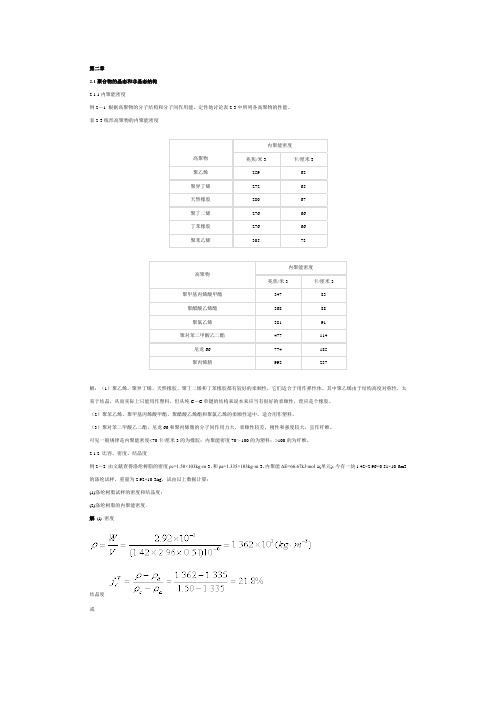
第二章2.1聚合物的晶态和非晶态结构2.1.1内聚能密度例2-1 根据高聚物的分子结构和分子间作用能,定性地讨论表2-3中所列各高聚物的性能。
表2-3线形高聚物的内聚能密度高聚物内聚能密度兆焦/米3 卡/厘米3聚乙烯259 62聚异丁烯272 65天然橡胶280 67聚丁二烯276 66丁苯橡胶276 66聚苯乙烯305 73高聚物内聚能密度兆焦/米3 卡/厘米3聚甲基丙烯酸甲酯347 83聚醋酸乙烯酯368 88聚氯乙烯381 91聚对苯二甲酸乙二酯477 114尼龙66 774 185聚丙烯腈992 237解:(1)聚乙烯、聚异丁烯、天然橡胶、聚丁二烯和丁苯橡胶都有较好的柔顺性,它们适合于用作弹性体。
其中聚乙烯由于结构高度对称性,太易于结晶,从而实际上只能用作塑料,但从纯C-C单键的结构来说本来应当有很好的柔顺性,理应是个橡胶。
(2)聚苯乙烯、聚甲基丙烯酸甲酯、聚醋酸乙烯酯和聚氯乙烯的柔顺性适中,适合用作塑料。
(3)聚对苯二甲酸乙二酯、尼龙66和聚丙烯腈的分子间作用力大,柔顺性较差,刚性和强度较大,宜作纤维。
可见一般规律是内聚能密度<70卡/厘米3的为橡胶;内聚能密度70~100的为塑料;>100的为纤维。
2.1.2 比容、密度、结晶度例2-2 由文献查得涤纶树脂的密度ρc=1.50×10³kg·m-3,和ρa=1.335×10³kg·m-3,内聚能ΔΕ=66.67kJ·mol-1(单元).今有一块1.42×2.96×0.51×10-6m3的涤纶试样,重量为2.92×10⁻³kg,试由以上数据计算:(1)涤纶树脂试样的密度和结晶度;(2)涤纶树脂的内聚能密度.解(l) 密度结晶度或(2) 内聚能密度文献值CED=476(J·cm-3)例2-3 试从等规聚丙烯结晶(α型)的晶胞参数出发,计算完全结晶聚丙烯的比容和密度。
塑料 结晶 表征

塑料结晶表征
塑料结晶表征是指对塑料的结晶度、晶体结构和晶体形态进行表征和测量的方法。
结晶度是指塑料中结晶区域所占的比例,直接影响塑料的性能和加工性能。
以下是几种常见的塑料结晶表征方法:
1.密度法:通过测量塑料的密度,可以间接推算出其结晶度。
一般来说,结
晶度越高,密度越大。
2.X射线衍射法:利用X射线在结晶区域和非结晶区域衍射强度的不同,可
以区分结晶度和晶体结构。
通过分析衍射图谱,可以得到结晶度、晶格常数、晶面间距等参数。
3.红外光谱法:通过分析红外光谱的吸收峰和指纹图谱,可以区分不同塑料
的结晶度和晶体结构。
该方法具有较高的灵敏度和分辨率。
4.热分析法:通过测量塑料在加热过程中的热性能变化,如熔点、热分解温
度等,可以推断其结晶度和晶体结构。
常见的热分析方法有差示扫描量热法(DSC)和热重分析法(TGA)。
以上都是比较常见的塑料结晶表征方法,选择何种方法取决于具体的应用需求和实验条件。
总结来说,塑料结晶表征是指对塑料的结晶度、晶体结构和晶体形态进行表征和测量的方法,主要包括密度法、X射线衍射法、红外光谱法和热分析法等。
通过这些方法可以得到塑料的结晶度和晶体结构信息,有助于了解其性能和加工行为,并优化其应用。
密度法测结晶度的误差分析

密度法测结晶度的误差分析
粘度法测高聚物分子量受诸多因素影响。
比如:温度,气压(液体上下表面气压差),粘度管口径,粘度管是否垂直及是否干净,溶液密度,人的读数误差,秒表精度等;而其测定的分子质量有限,只能在高聚物超过或不满的都不能测定。
除此之外还需要注意:
1、在实际测量材料的密度时,所选被测液体应符合下列要求:
(1)能满足所需的密度范围。
(2)不被试样吸收、不与试样发生任何化学反应和物理作用。
(3)两种液体能以任何比例相互混合。
(4)两种液体混合时不发生任何化学反应。
(5)具有低的粘度和挥发性。
(6)价廉、易得。
2、毛细管口的液滴必须在比重瓶离开恒温槽之前擦掉,否则,当比重瓶从恒温槽取出后,由于室温较低,使毛细管液面下降,影响测定结果。
3、为了消除偶然误差,对装液和称重操作必须重复三次以上,取其平均值。
密度法测定聚合物结晶度

实验2密度法测定聚合物结晶度一.实验目的1.学习密度法测定聚合物结晶度的原理和方法。
2.区别和理解用体积百分数和重量百分数表示的结晶度。
2.掌握比重瓶的正确使用方法。
二.实验原理在聚合物的聚集态结构中,分子链排列的有序状态不同,其密度就不同。
有序程度愈高,分子堆积愈紧密,聚合物密度就愈大,或者说比容愈小。
聚合物在结晶时,分子链在晶体中作有序密堆积,使晶区的密度c ρ高于非晶区的密度a ρ。
如果采用两相结构模型,即假定结晶聚合物由晶区和非晶区两部分组成,且聚合物晶区密度与非晶区密度具有线性加和性,则:a V c c V c f f ρρρ)1(−+= (23-1)进而可得:a c aV c f ρρρρ−−=(23-2)若假定晶区和非晶区的比容具有加和性,则:a W c c W c f f υυυ)1(−+= (23-3)得:ca aca a W c f ρρρρυυυυ1111−−=−−=(23-4)式中:ρ,c ρ,a ρ分别为聚合物、晶区和非晶区的密度;υ,c υ,a υ分别为聚合物、晶区和非晶区的比容;V c f :用体积百分数表示的结晶度; W c f :用重量百分数表示的结晶度。
由式(23-3)和式(23-4)可知,若已知聚合物试样完全结晶体的密度c ρ和聚合物试样完全非结晶体的密度a ρ,只要测定聚合物试样的密度ρ,即可求得其结晶度。
本实验采用悬浮法,测定聚合物试样的密度,即在恒温条件下,在加有聚合物试样的试管中,调节能完全互溶的两种液体的比例,待聚合物试样不沉也不浮,而是悬浮在混合液体中部时,根据阿基米德定律可知,此时混合液体的密度与聚合物试样的密度相等,用比重瓶测定该混合液体的密度,即可得聚合物试样的密度。
三.仪器和试剂1.25 ml 比重瓶一只;50ml 试管一支;玻璃搅拌棒一根; 滴管2支;卷筒纸和电子天平。
2.聚乙烯试样A (粒状);聚乙烯试样B (片装);蒸馏水;95%乙醇(CP )。
密度法测定聚合物结晶度
密度法测定聚合物结晶度在我们的日常生活中,聚合物无处不在。
想象一下,你身边的塑料瓶、购物袋、甚至是那些神奇的保鲜膜,它们都是聚合物的杰作。
哇,这些看似简单的物品其实蕴藏着复杂的科学原理。
今天,我们来聊聊一个有趣的主题,密度法测定聚合物的结晶度。
听上去有点高深,但别担心,咱们慢慢来,把它说得简单易懂,保证你听了之后不至于头晕脑胀。
结晶度这个词可能让你想起那些古老的宝石,闪闪发光。
不过在聚合物的世界里,结晶度其实是个很关键的概念。
简单来说,就是指聚合物分子链的有序程度。
结晶度越高,聚合物就越结实,物理性能也就越好。
就像你喝的可乐,瓶子硬邦邦的,说明它的聚合物结晶度高,反之则可能不那么耐用。
那我们怎么来测定这种结晶度呢?密度法就是一个不错的选择。
说到密度法,你可能会想,“这不是测水的嘛?”其实不然。
密度是物质的质量与体积之比,简单说,就是单位体积里装了多少东西。
就像你盛饭的时候,米饭和水的比例决定了碗里的重量。
聚合物的密度变化跟结晶度息息相关。
高结晶度的聚合物,密度通常会比较高,因为分子链紧紧地挤在一起,空间利用得很巧妙。
具体操作是怎样的呢?其实挺简单的。
你得准备好样品,把它称重,看看它的“身价”有多高。
然后,把它放入特定的液体中,比如说水或者某些有机溶剂。
这里有个小窍门,选对液体非常关键。
要确保这个液体的密度和你聚合物的密度差不多,这样才能精准地“探测”出聚合物的结晶度。
样品在液体中的浮沉情况就会告诉你结晶度的高低。
浮得越好,说明结晶度越低;沉得越快,则结晶度越高。
在这个过程中,你会发现,聚合物的神秘面纱一点点被揭开。
每一次实验都像是在解谜,每一个数据都在告诉你它的秘密。
你会感叹,科学原来如此有趣,聚合物的世界如此精彩。
通过密度法,我们不仅可以了解聚合物的结晶度,还能揭示它在实际应用中的表现。
比如说,塑料袋的强度和韧性可能和它的结晶度有关。
高结晶度的塑料袋,扛得住重物;而低结晶度的袋子,可能经不起一点儿压力就撕裂。
高分子物理第二章习题及解答
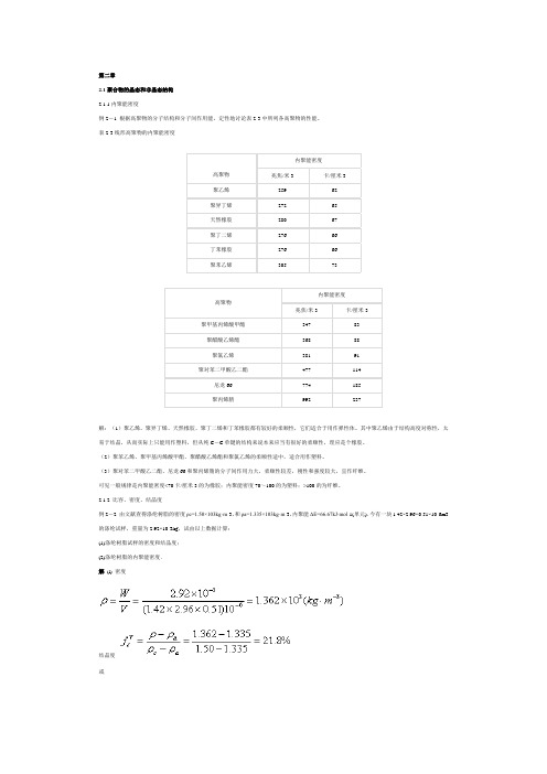
第二章2.1聚合物的晶态和非晶态结构2.1.1内聚能密度例2-1 根据高聚物的分子结构和分子间作用能,定性地讨论表2-3中所列各高聚物的性能。
表2-3线形高聚物的内聚能密度高聚物内聚能密度兆焦/米3 卡/厘米3聚乙烯259 62聚异丁烯272 65天然橡胶280 67聚丁二烯276 66丁苯橡胶276 66聚苯乙烯305 73高聚物内聚能密度兆焦/米3 卡/厘米3聚甲基丙烯酸甲酯347 83聚醋酸乙烯酯368 88聚氯乙烯381 91聚对苯二甲酸乙二酯477 114尼龙66 774 185聚丙烯腈992 237解:(1)聚乙烯、聚异丁烯、天然橡胶、聚丁二烯和丁苯橡胶都有较好的柔顺性,它们适合于用作弹性体。
其中聚乙烯由于结构高度对称性,太易于结晶,从而实际上只能用作塑料,但从纯C-C单键的结构来说本来应当有很好的柔顺性,理应是个橡胶。
(2)聚苯乙烯、聚甲基丙烯酸甲酯、聚醋酸乙烯酯和聚氯乙烯的柔顺性适中,适合用作塑料。
(3)聚对苯二甲酸乙二酯、尼龙66和聚丙烯腈的分子间作用力大,柔顺性较差,刚性和强度较大,宜作纤维。
可见一般规律是内聚能密度<70卡/厘米3的为橡胶;内聚能密度70~100的为塑料;>100的为纤维。
2.1.2 比容、密度、结晶度例2-2 由文献查得涤纶树脂的密度ρc=1.50×10³kg·m-3,和ρa=1.335×10³kg·m-3,内聚能ΔΕ=66.67kJ·mol-1(单元).今有一块1.42×2.96×0.51×10-6m3的涤纶试样,重量为2.92×10⁻³kg,试由以上数据计算:(1)涤纶树脂试样的密度和结晶度;(2)涤纶树脂的内聚能密度.解(l) 密度结晶度或(2) 内聚能密度文献值CED=476(J·cm-3)例2-3 试从等规聚丙烯结晶(α型)的晶胞参数出发,计算完全结晶聚丙烯的比容和密度。
密度法测定聚丙烯结晶度的实验研究

密度法测定聚丙烯结晶度的实验研究王燕来(北京燕山石油化工(集团)有限公司研究院 102549) 采用密度法测定聚丙烯的结晶度,分析了结晶高聚物的密度与结晶度之间的线性关系,并探讨了测定结果的精密度、不同制样方法的结果,通过与X 光衍射法进行对比,认为密度法简单、快速、可靠。
关键词: 聚丙烯 密度法 结晶度作 者 简 介王燕来 助工,1987年毕业于北京石油化工专科学校,一直从事密度仪、塑料产品物化性能的测试分析和研究工作。
聚丙烯树脂是分子链节排列高度规整的结晶型聚合物,它的结晶度直接影响其机械性能、耐老化性能、理化性能以及加工工艺等。
因此,通过密度法测定了解结晶度,可以大致评估聚丙烯树脂的几种重要性能,为聚丙烯的加工与应用快速地提供可靠的信息。
1 实验部分1.1 实验原理1.1.1 结晶度的测定密度法[1]测定高聚物结晶度的依据是:分子在晶体中作有序密堆砌,结晶区的密度高于非晶区的密度,假设试样的结晶度可按两部分的模型来求得,从密度的线性加和性出发,可得出结晶度与密度的关系如式(1)。
X (%)=Dc (D -Da )D (Dc -Da )×100(1)式中:X 结晶度,%;D 试样的密度,g/cm 3;Dc 完全结晶的试样的密度,g/cm 3;Da 完全无定形的试样的密度,g/cm 3;密度梯度法测定的物质的密度值与测定的温度有着密切的关系,把测定的温度考虑进去,本实验工作采用纳塔所给出的公式,在t ℃时密度与结晶度的关系如式(2)(薄膜测定除外)[2]。
X (%)=0.983+9(t +180)×10-4-1/d4.8(t +180)×10-6(2)式中:X 试样的结晶度,%;t 实验温度,℃;d 试样的密度,g/cm 3;1.1.2 密度的测定采用密度梯度柱法测定无规物与等规物不同配比的聚丙烯的密度。
配制密度梯度柱的方法是将两种密度不同而又能相互混合的液体进行适当的混合,由于扩散作用,混合后的液体从上部到下部的密度逐渐变大,且连续分布,形成梯度,称之为密度梯度柱。
ASTM D 1505-03用密度梯度法测定塑料密度的试验方法
Designation:D 1505–03Standard Test Method forDensity of Plastics by the Density-Gradient Technique 1This standard is issued under the fixed designation D 1505;the number immediately following the designation indicates the year of original adoption or,in the case of revision,the year of last revision.A number in parentheses indicates the year of last reapproval.A superscript epsilon (e )indicates an editorial change since the last revision or reapproval.This standard has been approved for use by agencies of the Department of Defense.1.Scope*1.1This test method covers the determination of the density of solid plastics.1.2This test method is based on observing the level to which a test specimen sinks in a liquid column exhibiting a density gradient,in comparison with standards of known density.N OTE 1—The comparable ISO document is ISO 1183–2.There has not been any data generated to date comparing the results of the ISO method with this method.1.3The values stated in SI units are to be regarded as the standard.1.4This standard does not purport to address all of the safety concerns,if any,associated with its use.It is the responsibility of the user of this standard to establish appro-priate safety and health practices and determine the applica-bility of regulatory limitations prior to use.2.Referenced Documents 2.1ASTM Standards:2D 941Test Method for Density and Relative Density (Spe-cific Gravity)of Liquids by Lipkin Bicapillary Pycnometer D 2839Practice for Use of a Melt Index Strand for Deter-mining Density of PolyethyleneD 4703Practice for Compression Molding Thermoplastic Materials into Test Specimens,Plaques,or SheetsE 691Practice for Conducting an Interlaboratory Study to Determine the Precision of a Test Method 2.2ISO Standard:ISO 1183-2Methods for Determining the Density and Rela-tive Density of Noncellular Plastics 33.Terminology 3.1Definition:3.1.1density of plastics —the weight per unit volume of material at 23°C,expressed as follows:D 23C ,g/cm 3(1)N OTE 2—Density is to be distinguished from specific gravity,which is the ratio of the weight of a given volume of the material to that of an equal volume of water at a stated temperature.4.Significance and Use4.1The density of a solid is a conveniently measurable property which is frequently useful as a means of following physical changes in a sample,as an indication of uniformity among samples,and a means of identification.4.2This test method is designed to yield results accurate to better than 0.05%.N OTE 3—Where accuracy of 0.05%or better is desired,the gradient tube shall be constructed so that vertical distances of 1mm shall represent density differences no greater than 0.0001g/cm.3The sensitivity of the column is then 0.0001g/cm 3·mm.Where less accuracy is needed,the gradient tube shall be constructed to any required sensitivity.5.Apparatus5.1Density-Gradient Tube —A suitable graduate with ground-glass stopper.45.2Constant-Temperature Bath —A means of controlling the temperature of the liquid in the tube at 2360.1°C.A thermostatted water jacket around the tube is a satisfactory and convenient method of achieving this.5.3Glass Floats —A number of calibrated glass floats cov-ering the density range to be studied and approximately evenly distributed throughout this range.5.4Pycnometer ,for use in determining the densities of the standard floats.5.5Liquids ,suitable for the preparation of a density gradi-ent (Table 1).N OTE 4—It is very important that none of the liquids used in the tube1This test method is under the jurisdiction of ASTM Committee D20on Plastic and is the direct responsibility of Subcommittee D20.70on Analytical Methods (Section D20.70.01).Current edition approved November 1,2003.Published January 2004.Originally approved in st previous edition approved in 1998as D 1505-98.2For referenced ASTM standards,visit the ASTM website,,or contact ASTM Customer Service at service@.For Annual Book of ASTM Standards volume information,refer to the standard’s Document Summary page on the ASTM website.3Available from American National Standards Institute (ANSI),25W.43rd St.,4th Floor,New York,NY 10036.4Tubes similar to those described in Refs (6)and (12)may also be used.1*A Summary of Changes section appears at the end of this standard.Copyright ©ASTM International,100Barr Harbor Drive,PO Box C700,West Conshohocken,PA 19428-2959,United States.exert a solvent or chemical effect upon the test specimens during the time of specimen immersion.5.6Hydrometers —A set of suitable hydrometers covering the range of densities to be measured.These hydrometers should have 0.001density graduations.5.7Analytical Balance ,with a sensitivity of 0.001g.5.8Siphon or Pipet Arrangement ,for filling the gradient tube.This piece of equipment should be constructed so that the rate of flow of liquid may be regulated to 1065mL/min.6.Test Specimen6.1The test specimen shall consist of a piece of the material under test.The piece may be cut to any shape convenient for easy identification,but should have dimensions that permit the most accurate position measurement of the center of volume of the suspended specimen (Note 5).Care should be taken in cutting specimens to avoid change in density resulting from compressive stress.N OTE 5—The equilibrium positions of film specimens in the thickness range from 0.025to 0.051mm (0.001to 0.002in.)may be affected by interfacial tension.If this affect is suspected,films not less than 0.127mm (0.005in.)in thickness should be tested.6.2The specimen shall be free of foreign matter and voids and shall have no cavities or surface characteristics that will cause entrapment of bubbles.7.Preparation of Density-Gradient Columns7.1Preparation of Standard Glass Floats 5—Prepare glass floats by any convenient method such that they are fully annealed,approximately spherical,have a maximum diameter less than one fourth the inside diameter of the column,and do not interfere with the test specimens.Prepare a solution (400to 600mL)of the liquids to be used in the gradient tube such that the density of the solution is approximately equal to the desired lowest density.When the floats are at room temperature,drop them gently into the solution.Save the floats that sink very slowly,and discard those that sink very fast,or save them for another tube.If necessary to obtain a suitable range of floats,grind selected floats to the desired density by rubbing the head part of the float on a glass plate on which is spread a thin slurry of 400or 500-mesh silicon carbide (Carborundum)or otherappropriate abrasive.Progress may be followed by dropping the float in the test solution at intervals and noting its change in rate of sinking.7.2Calibration of Standard Glass Floats (see Appendix X1):7.2.1Place a tall cylinder in the constant-temperature bath maintained at 2360.1°C.Then fill the cylinder about two thirds full with a solution of two suitable liquids selected from Table 1,the density of which can be varied over the desired range by the addition of either liquid to the mixture.After the cylinder and solution have attained temperature equilibrium,place the float in the solution,and if it sinks,add the denser liquid by suitable means with good stirring until the float reverses direction of movement.If the float rises,add the less dense liquid by suitable means with good stirring until the float reverses direction of movement.7.2.2When reversal of movement has been observed,re-duce the amount of the liquid additions to that equivalent to 0.0001-g/cm 3density.When an addition equivalent to 0.0001-g/cm 3density causes a reversal of movement,or when the float remains completely stationary for at least 15min,the float and liquid are in satisfactory balance.The cylinder must be covered whenever it is being observed for balance,and the liquid surface must be below the surface of the liquid in the constant-temperature bath.After vigorous stirring,the liquid may continue to move for a considerable length of time;make sure that the observed movement of the float is not due to liquid motion by waiting at least 15min after stirring has stopped before observing the float.7.2.3When balance has been obtained,fill a freshly cleaned and dried pycnometer with the solution and place it in the 2360.1°C bath for sufficient time to allow temperature equilib-rium of the glass.Determine the density of the solution by normal methods (Test Method D 941)and make “in vacuo”corrections for all weighings.Record this as the density of the float.Repeat the procedure for each float.7.3Gradient Tube Preparation (see appendix for details):7.3.1Method A —Stepwise addition.7.3.2Method B —Continuous filling (liquid entering gradi-ent tube becomes progressively less dense).7.3.3Method C —Continuous filling (liquid entering gradi-ent tube becomes progressively more dense).8.Conditioning8.1Test specimens whose change in density on conditioning may be greater than the accuracy required of the density determination shall be conditioned before testing in accordance with the method listed in the applicable ASTM material specification.9.Procedure9.1Wet three representative test specimens with the less dense of the two liquids used in the tube and gently place them in the tube.Allow the tube and specimens to reach equilibrium,which will require 10min or more.Thin films of 1to 2mils in thickness require approximately 11⁄2h to settle,and rechecking after several hours is advisable (Note 4).9.2Read the height of each float and each specimen by a line through the individual center of volume and averaging the5Glass floats may be purchased from American Density Materials,3826Springhill Rd.Staunton,V A 24401,Ph:(540)887-1217.TABLE 1Liquid Systems for Density-Gradient TubesSystemDensity Range,g/cm 3Methanol-benzyl alcohol 0.80to 0.92Isopropanol-water0.79to 1.00Isopropanol-diethylene glycol 0.79to 1.11Ethanol-carbon tetrachloride 0.79to 1.59Toluene-carbon tetrachloride 0.87to 1.59Water-sodium bromide 1.00to 1.41Water-calcium nitrate1.00to 1.60Carbon tetrachloride-trimethylene dibromide 1.60to 1.99Trimethylene dibromide-ethylene bromide 1.99to2.18Ethylene bromide-bromoform2.18to2.89three values.When a cathetometer is used,measure the height of thefloats and specimens from an arbitrary level using a line through their center of volume.If equilibrium is not obtained, the specimen may be imbibing the liquid.9.3Old samples can be removed without destroying the gradient by slowly withdrawing a wire screen basket attached to a long wire(Note6).This can be conveniently done by means of a clock motor.Withdraw the basket from the bottom of the tube and,after cleaning,return it to the bottom of the tube.It is essential that this procedure be performed at a slow enough rate(approximately30min/300-mm length of column) so that the density gradient is not disturbed.N OTE6—Whenever it is observed that air bubbles are collecting on samples in the column,a vacuum applied to the column will correct this.10.Calculation10.1The densities of the samples may be determined graphically or by calculation from the levels to which the samples settle by either of the following methods:10.1.1Graphical Calculation—Plotfloat position versus float density on a chart large enough to be read accurately to 61mm and the desired precision of density.Plot the positions of the unknown specimens on the chart and read their corre-sponding densities.10.1.2Numerical Calculation—Calculate the density by interpolation as follows:Density at x5a1[~x2y!~b2a!/~z2y!#(2) where:a and b=densities of the two standardfloats,y and z=distances of the two standards,a and b,respec-tively,bracketing the unknown measured froman arbitrary level,andx=distance of unknown above the same arbitrary level.11.Report11.1Report the following information:11.1.1Density reported as D23C,in grams per cubic centimetre,as the average for three representative test speci-mens,11.1.2Number of specimens tested if different than three, 11.1.3Sensitivity of density gradient in grams per cubic centimetre per millimetre,11.1.4Complete identification of the material tested,and 11.1.5Date of the test.12.Precision and Bias612.1Specimens Molded in One Laboratory and Tested in Several Laboratories—An interlaboratory test was run in1981 in which randomized density plaques were supplied to22 laboratories.Four polyethylene samples of nominal densities of0.92to0.96g/cm3were molded in one laboratory.The data were analyzed using Practice E691,and the results are given in Table2.12.2Specimens Molded and Tested in Several Laboratories: 12.2.1Samples Prepared Using Practice D4703in Each Laboratory—Table3is based on a round robin9conducted in 1994in accordance with Practice E691,involving seven materials tested by7to11laboratories.For each material,all of the samples were prepared by each laboratory,molded in accordance with Procedure C of Annex A1of Practice D4703, and tested using this test method.The data are for comparison with the data of the same samples tested by Practice D2839. Each test result is an individual determination.Each laboratory obtained six test results for each material.12.2.2Samples Prepared Using Practice D2839in Each Laboratory—Table4is based on a round robin9conducted in 1994in accordance with Practice E691,involving seven materials tested by10to15laboratories.For each material,all of the samples were prepared by each laboratory in accordance with Practice D2839.Each test result is an individual deter-mination.Each laboratory obtained six test results for each material.12.3Concept of r and R—Warning—The following expla-nations of r and R(12.3-12.3.3)are only intended to present a meaningful way of considering the approximate precision of this test method.The data in Table1should not be rigorously applied to acceptance or rejection of material,as those data are specific to the round robin and may not be representative of other lots,conditions,materials,or ers of this test method should apply the principles outlined in Practice E691to generate data specific to their laboratory and materi-als,or between specific laboratories.The principles of12.3-12.3.3would then be valid for each data.If S r and S R have been calculated from a large enough body of data,and for test results that were averages from testing one specimen:12.3.1Repeatability Limit,r(Comparing two test results for the same material,obtained by the same operator using the 6Supporting data are available from ASTM Headquarters.Request RR:D20-1123.TABLE2Precision Data Summary—Polyethylene DensityMaterial Average Density,g/cm3S r A S R B r C R D10.91960.000290.001060.000820.004520.93190.000120.000800.000340.002330.95270.000330.001160.000930.003340.96230.000620.001140.001800.0033A Sr=within-laboratory standard deviation for the indicated material.It is obtained by pooling the within-laboratory standard deviations of the test results from all of the participating laboratories.B SR =between-laboratories reproducibility,expressed as standard deviation,for the indicated material.C r=within-laboratory repeatability limit=2.8Sr .D R=between-laboratories reproducibility limit=2.8SR.same equipment on the same day)—The two test results should be judged not equivalent if they differ by more than the r value for that material.12.3.2Reproducibility Limit,R (Comparing two test results for the same material,obtained by different operators using different equipment in different laboratories)—The two test results should be judged not equivalent if they differ by more than the R value for that material.12.3.3Any judgment in accordance with 12.2.1or 12.2.2would have an approximate 95%(0.95)probability of being correct.12.3.4Bias —There are no recognized standards by which to estimate the bias of this test method.13.Keywords13.1density;film;gradient;plaque;polyolefins;polyeth-ylene;polypropylene;preparationAPPENDIXES(Nonmandatory Information)X1.FLOAT CALIBRATION—ALTERNATIVE TEST METHODX1.1This test method of float calibration has been found by one laboratory to save time and give the same accuracy as the standard test method.Its reliability has not been demon-strated by round-robin data.X1.1.1Prepare a homogeneous solution whose density is fairly close to that of the float in question.X1.1.2Fill a graduate about 3⁄4full with the solution,drop in the float,stopper,and place in a thermostatted water bath near 23°C.Fill a tared two-arm pycnometer (Test Method D 941,or equivalent)with the solution.Place the pycnometer in the bath.X1.1.3Vary the bath temperature until the solution density is very near to that of the float.(If the float was initially on the bottom of the graduate,lower the bath temperature until the float rises;if the float floated initially,raise the bath tempera-ture until the float sinks to the bottom.)X1.1.4Change the bath temperature in the appropriate direction in increments corresponding to solution density increments of about 0.0001g/cm 3until the float reverses direction of movement as a result of the last change.This must be done slowly (at least 15-min intervals between incremental changes on the temperature controller).Read the volume of liquid in the pycnometer.X1.1.5Change the bath temperature in increments in the opposite direction,as above,until a change in the float position again occurs.Read the volume of liquid in the pycnometer.N OTE X1.1—The float should rise off the bottom of its own volition.As a precaution against surface tension effects when the float is floating,the float should be pushed about halfway down in the liquid column and then observed as to whether it rises or falls.For this purpose,a length of Nichrome wire,with a small loop on the lower end and an inch or so of length extending above the liquid surface,is kept within the graduate throughout the course of the run.To push a floating float down,the cylinder is unstoppered and the upper wire end grasped with tweezers for the manipulations.The cylinder is then quickly restoppered.X1.1.6Remove the pycnometer from the bath,dry the outside,and set aside until the temperature reaches ambient temperature.Weigh and calculate the “in vacuo”mass of solution to ing the average of the two observed solution volumes,calculate the density of the solution to 0.0001g/cm 3.This solution density is also the float density.X1.1.7The pycnometer used should be calibrated for vol-ume from the 23°C calibration,although the reading is taken at a different temperature.The alternative test method is based on a number of unsupported assumptions but generally gives the same results as that described in 7.2within the accuracyTABLE 3Precision Data—Density,g/cm 3Material Number ofLaboratoriesDensity,g/cm 3S r A S R B r C R DB 70.91390.000290.000880.000810.00245F 80.91770.000180.000790.000510.00221G 80.92200.000280.000710.000780.00197A 110.93560.000360.001050.001000.00294E 110.95280.000460.001180.001290.00331C 100.96190.001000.001000.001030.00281D90.96330.000360.001370.001010.00384AS r =within-laboratory standard deviation for the indicated material.It is obtained by pooling the within-laboratory standard deviations of the test results from all of the participating laboratories.BS R =between-laboratories reproducibility,expressed as standard deviation,for the indicated material.Cr =within-laboratory repeatability limit =2.8S r .DR =between-laboratories reproducibility limit =2.8S R .TABLE 4Density,g/cm 3,Samples Prepared in Accordance WithPractice D 2839MaterialNumber ofLaboratoriesDensity,g/cm 3S r A S R B r C R D B 100.91390.000260.000780.000720.00219F 120.91790.000200.000780.000550.00220G 130.92220.000300.000730.000850.00206A 150.93570.000410.000800.001150.00225E 140.95300.000390.000920.001090.00258C 110.96150.000300.000730.000850.00206D100.96260.000530.001090.001480.00305AS r =within-laboratory standard deviation for the indicated material.It is obtained by pooling the within-laboratory standard deviations of the test results from all of the participating laboratories.BS R =between-laboratories reproducibility,expressed as standard deviation,for the indicated material.Cr =within-laboratory repeatability limit =2.8S r .DR =between-laboratories reproducibility limit =2.8S R.required.In case of disagreement,the method described in7.2shall be the referee method.X2.GRADIENT TUBE PREPARATIONX2.1Method A—Stepwise Addition:X2.1.1Using the two liquids that will give the desireddensity range,and sensitivity(S)in grams per cubic centimetreper millimetre,prepare four or more solutions such that eachdiffers from the next heavier by80S g/cm3.The number ofsolutions will depend upon the desired density range of thecolumn and shall be determined as follows:Numbers of solutions to prepare density2gradient(X2.1)column~Note X2.1!5~11D22D1!/80S(X2.1)where:D2=upper limit of density range desired,D1=lower limit of density range desired,andS=sensitivity,in grams per cubic centimetre per milli-metre.N OTE X2.1—Correct the value of(1+D2−D1)/80S to the nearestwhole number.To prepare these solutions,proceed as follows:Using the hydrometers,mix the two liquids in the proportions necessary to obtain the desired solutions.Remove the dissolved air from the solutions by gentle heating or an applied vacuum.Then check the density of the solutions at2360.1°C by means of the hydrometers and,if necessary,add the appropriate air-free liquid until the desired density is obtained.N OTE X2.2—Where aqueous mixtures are used,0.5%aqueous sodium acetate should be used to prepare the mixture.This reduces the formation of bubbles from dissolution.N OTE X2.3—In order to obtain a linear gradient in the tube,it is very important that the solutions be homogeneous and at the same temperature when their densities are determined.It is also important that the density difference between the solutions consecutively introduced into the tube be equal.X2.1.2By means of a siphon or pipet,fill the gradient tube with an equal volume of each liquid starting with the heaviest, taking appropriate measures to prevent air from being dis-solved in the liquid.After the addition of the heaviest liquid, very carefully and slowly pour an equal volume of the second heaviest liquid down the side of the column by holding the siphon or pipet against the side of the tube at a slight angle. Avoid excess agitation and turbulence.In this manner,the “building”of the tube shall be completed.N OTE X2.4—Density gradients may also be prepared by reversing the procedure described in X2.1.1and X2.1.2.When this procedure is used, the lightest solution is placed in the tube and the next lightest solution is very carefully and slowly“placed”in the bottom of the tube by means of a pipet or siphon which just touches the bottom of the tube.In this manner the“building”of the tube shall be completed.X2.1.3If the tube is not already in a constant-temperature bath,transfer the tube,with as little agitation as possible,to the constant-temperature bath maintained at2360.1°C.The bath level should approximately equal that of the solution in the tube,and provision should be made for vibrationless mounting of the tube.X2.1.4For every254mm of length of tube,dip a minimum offive clean calibratedfloats,spanning the effective range of the column,into the less dense solvent used in the preparation of the gradient tube and add them to the tube.By means of a stirrer(for example,a small coiled wire or other appropriate stirring device)mix the different layers of the tube gently by stirring horizontally until the least dense and most densefloats span the required range of the gradient tube.If,at this time,it is observed that thefloats are“bunched”together and not spread out evenly in the tube,discard the solution and repeat the procedure.Then cap the tube and keep it in the constant-temperature bath for a minimum of24h.X2.1.5At the end of this time,plot the density offloats versus the height offloats to observe whether or not a fairly smooth and nearly linear curve is obtained.Some small irregularities may be seen,but they should be slight.Whenever an irregular curve is obtained,the solution in the tube shall be discarded and a new gradient prepared.N OTE X2.5—Gradient systems may remain stable for several months. X2.2Method B—Continuous Filling with Liquid Entering Gradient Tube Becoming Progressively Less Dense:X2.2.1Assemble the apparatus as shown in Fig.X2.1,using beakers of the same diameter.Then select an appropriate amount of two suitable liquids which previously have been carefully deaerated by gentle heating or an applied vacuum. Typical liquid systems for density-gradient tubes are listed in Table1.The volume of the more dense liquid used in the mixer (Beaker B shown in Fig.X2.1)must be equal to at least one half of the total volume desired in the gradient tube.An FIG.X2.1Apparatus for Gradient TubePreparationestimate of the volume of the less dense liquid required in Beaker A to establishflow from A to B can be obtained from the following inequality:V A.d B V B/d A(X2.2) where:V A=starting liquid volume in Beaker A,V B=starting liquid volume in Beaker B,d A=density of the starting liquid in Beaker A,andd B=density of the starting liquid in Beaker B.A small excess(not exceeding5%)over the amount indicated by the preceding equality will induce the required flow from A toB and yield a very nearly linear gradient column.X2.2.2Place an appropriate volume of the denser liquid into Beaker B of suitable size.Prime the siphon between Beaker B and the gradient tube with liquid from Beaker B and then close the stopcock.The delivery end of this siphon should be equipped with a capillary tip forflow control.N OTE X2.6—Techniques acceptable for transfer of liquid into the gradient tube are siphon/gravity,vacuum-filling,use of a peristatic pump, or any other technique useful to transfer liquids in a controlled manner.It is important to control theflow in order to maintain a desirable gradient. X2.2.3Place an appropriate volume of the less dense liquid into Beaker A.Prime the siphon between Beakers A and B with the liquid from Beaker A and close the stopcock.Start the highspeed,propeller-type stirrer in Beaker B and adjust the speed of stirring such that the surface of the liquid does not fluctuate greatly.X2.2.4Start the delivery of the liquid to the gradient tube by opening the necessary siphon-tube stopcocks simultaneously. Adjust theflow of liquid into the gradient tube at a very slow rate,permitting the liquid toflow down the side of the tube.Fill the tube to the desired level.N OTE X2.7—Preparation of a suitable gradient tube may require1to 11⁄2h or longer,depending upon the volume required in the gradient tube. X2.3Method C—Continuous Filling with Liquid Entering Gradient Tube Becoming Progressively More Dense:X2.3.1This method is essentially the same as Method B with the following exceptions:X2.3.2The lighter of the two liquids is placed in Beaker B. X2.3.3The liquid introduced into the gradient column is introduced at the bottom of the column.Thefirst liquid introduced is the lighter end of the gradient and is constantly pushed up in the tube as the liquid being introduced becomes progressively heavier.X2.3.4The liquid from Beaker A must be introduced into Beaker B by directflow from the bottom of Beaker A to the bottom of Beaker B,rather than being siphoned over as it is in Method B.Filling the tube by this method may be done more rapidly than by Methods A or B.The stopcock between Containers A and B should be of equal or larger bore than the outlet stopcock.A schematic drawing of the apparatus for Method C is shown in Fig.X2.2.REFERENCES (1)Linderstrøm-Lang,K.,“Dilatometric Ultra-Micro-Estimation of Pep-tidase Activity,”Nature,NATRA,V ol139,1937,p.713.(2)Linderstrøm-Lang,K.,and Lanz,H.,“Enzymic Histochemistry XXIXDilatometric Micro-Determination of Peptidase Activity,”Comptesrendus des gravaus de laboratorie Carlsberg,Serie Chimique,V ol21,1938,p.315.(3)Linderstrøm-Lang,K.,Jacobsen,O.,and Johansen,G.,“Measurementof the Deuterium Content in Mixtures of H2O and D2O,”ibid.,V ol23,1938,p.17.(4)Jacobsen,C.F.,and Linderstrøm-Lang,K.,“Method for Rapid Deter-mination of Specific Gravity,”Acta Physiologica Scandinavica,AP-SCA,V ol1,1940,p.149.(5)Boyer,R.F.,Spencer,R.S.,and Wiley,R.M.,“Use of Density-Gradient Tube in the Study of High Polymers,”Journal of Polymer Science,JPSCA,V ol1,1946,p.249.(6)Anfinsen,C.,“Preparation and Measurement of Isotopic Tracers:ASymposium Prepared for the Isotope Research Group,”Edwards,J.W.,Publishers,Ann Arbor,MI,1946,p.61.(7)Tessler,S.,Woodberry,N.T.,and Mark,H.,“Application of theDensity-Gradient Tube in Fiber Research,”Journal of Polymer Sci-ence,JPSCA,V ol1,1946,p.437.(8)Low,B.W.,and Richards,F.M.,“The Use of the Gradient Tube forthe Determination of Crystal Densities,”Journal of the American Chemical Society,JACSA,V ol74,1952,p.1660.(9)Sperati,C.A.,Franta,W.A.,and Starkweather,H.W.,Jr.,“TheMolecular Structure of Polyethylene V,the Effect of Chain Branching and Molecular Weight on Physical Properties,”Journal of the Ameri-can Chemical Society,JACSA,V ol75,1953,p.6127.(10)Tung,L.H.,and Taylor,W.C.,“An Improved Method of PreparingDensity Gradient Tubes,”Journal of Polymer Science,JPSCA,V ol 21,1956,p.144.(11)Mills,J.M.,“A Rapid Method of Construction Linear DensityGradient Columns,”Journal of Polymer Science,V ol19,1956,p.585.(12)Wiley,R.E.,“Setting Up a Density Gradient Laboratory,”PlasticsTechnology,PLTEA,V ol8,No.3,1962,p.31.FIG.X2.2Apparatus for Gradient TubePreparation。
密度梯度管法测定高聚物的密度和结晶度
实验1 密度梯度管法测定高聚物的密度和结晶度高聚物的密度是高聚物的重要物理参数之一,它对于指导高聚物的合成、成型工艺以及探索结构与性能之间的关系等方面都是不可缺少的数据。
而对于结晶高聚物来说,结晶度反映了物质内部结构规则程度,影响着其许多物理、化学性能和应用性能,密度和结晶度之间有着密切的关系。
因此,测定高聚物的密度和结晶度,对研究其结构状态进而控制材料的性能有着很大的实用意义。
测定高聚物结晶度的方法很多,有X-射线衍射法、红外吸收光谱法、核磁共振法、差热分析法、反相色谱法、化学方法(水解法、甲酰化法、氘交换法)、密度法等等。
其中前几种方法都需要使用复杂的仪器设备,而密度法是从较容易测定的高聚物密度换算成结晶度,既简单易行,又较为准确。
凡是能测定出高聚物试样密度的方法都属于密度法。
本实验采用密度法中的一种方法 ── 密度梯度管法测定高聚物的结晶度。
一、实验目的1. 了解用密度梯度管法测定高聚物的密度和结晶度的基本原理和方法。
2. 学会用连续灌注法制备密度梯度管的技术及密度梯度管的标定方法。
3. 用密度梯度管测定结晶高聚物试样的密度,并计算其结晶度。
二、实验原理将两种密度不同且又能互溶的液体配制成一系列等差密度的混合液,并按照低密度液体(轻液)位于高密度液体(重液)之上的层次,把不同密度的混合液置于带有刻度的玻璃管中,由于液体分子的扩散作用,管中的液体密度将会从下到上呈连续的线性分布,这就是密度梯度管。
当把一个颗粒状试样放入密度梯度管中时,根据悬浮原理,试样会在与其密度相等的液位上悬浮不动。
配制密度梯度管所选用的轻液和重液种类不同时,密度梯度管的密度梯度范围就会不同。
在本实验后面的附表1-1中列出了一些常用的密度梯度管溶液体系。
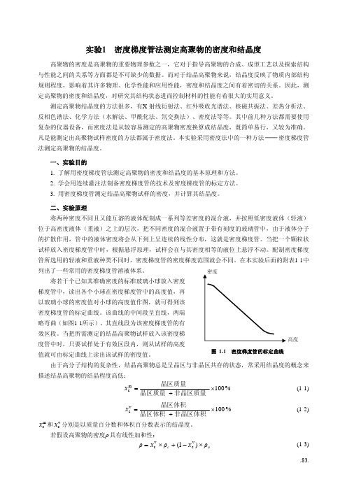
高度图 1-1 密度梯度管的标定曲线将若干个已知其准确密度的标准玻璃小球放入密度梯度管中,读出各个小球在密度梯度管中的高度值,再以玻璃小球的密度值对小球的高度值作图,就可得到该密度梯度管的标定曲线。
实验1 密度梯度管法测定聚合物的密度和结晶度
实验1 密度梯度管法测定聚合物的密度和结晶度1. 实验目的(1)掌握密度梯度管法测定聚合物密度和结晶度的基本原理。
(2)学会以连续注入法制备密度梯度管的技术及密度梯度的标定方法。
(3)用密度梯度管法测定聚合物的密度,并由密度计算结晶度。
2. 实验原理聚合物密度是聚合物物理性质的一个重要指标,是判定聚合物产物、指导成型加工和探索聚集态结构与性能之间关系的一个重要数据。
尤其是结晶性聚合物,结晶度是聚合物性质中很重要的指标,密度与表征内部结构规则程度的结晶度有密切的关系。
因此,通过聚合物密度和结晶度的测定,研究结构状态进而控制材料的性质。
密度梯度管法是利用悬浮原理测定高聚物密度的常用方法,具有设备简单、操作容易、应用灵活,准确快速、能同时测定在一个相当范围内的不同密度试样的优点。
对于密度相差极小的试样,更是一种有效的高灵敏度的测定方法。
聚合物结晶度的测定方法很多,有X -射线衍射法、红外吸收光谱法、差热分析法、反相色谱法等,但这些方法都需要复杂的仪器设备,而用密度梯度管法从测得的密度换算到结晶度,设备简单且数据可靠,是测定结晶度的常用方法。
密度梯度管是一个有刻度的柱形玻璃管,选用不同密度的可以互相混溶的两种液体,配制成一系列等差密度混合液,按低密度(轻液)居上,高密度(重液)居下的层次,以等体积分次地注入到柱形玻璃管中,由液体分子自行扩散;也可由两种液体经适当地混合和自流,使连续注入管中的液体不断改变密度。
最后形成密度从上至下逐渐增大,并呈现连续的线性分布的液柱,通称为密度梯度管或密度梯度柱。
再将已知准确密度的6~8个玻璃小球(φ≈3mm )投入管中,标定液柱的密度梯度。
以小球密度对其在液柱中的高度作图,得一曲线(图2-1),其中间一段呈直线,两端略弯曲。
向管中投入被测试样后,试样下沉至与其密度相等的位置就悬浮着,测试试样在管中的高度后,由密度-液柱高度的直线关系图上查出试样的密度。
也可用内插法计算试样的密度。
聚合物密度和结晶度的测定
聚合物密度和结晶度的测定聚合物密度和结晶度的测定一、实验目的1. 掌握密度计测定聚合物密度和结晶度的基本原理。
2. 用密度计测定聚合物的密度,并由密度计算结晶度。
二、实验原理聚合物密度是聚合物物理性质的一个重要指标,是判断聚合物产物、指导成型加工和探索聚集态结构与性能之间关系的一个重要数据。
对于结晶性聚合物,常用结晶度表征内部结构规则程度,而密度与结晶度有密切的关系。
因此,可通过聚合物密度和结晶度的测定来研究结构状态,进而控制材料的性质。
密度天平利用阿基米德原理测定物质的密度,可测固体、液体、浮体、颗粒、粉末、粘稠体、海棉体,具有操作简单、直接的优点。
结晶性聚合物都是部分结晶的,即晶区和非晶区共存。
而晶区和非晶区的密度不同。
因此,同一聚合物由于结晶度不同,样品的密度不同。
如采用两相结合模型,并假定比容(密度的倒数)具有加和性,即结晶性聚合物的比容等于晶区和非晶区比容的线性加和,则有:111 (公式 1) ,,,f,1,fcc,,, ca式中,fc为结晶度,ρc为晶区密度,ρa为非晶区密度则从测得的聚合物试样密度可计算出结晶度:,,,,,,caf,,100%c (公式 2),,,,,,ca三、实验仪器及试剂实验仪器:密度天平(型号AND EK-300iD,产地:日本) 实验试剂:锡粒、聚氯乙烯板。
高密度聚乙烯(粒料) 四、实验步骤(一)聚合物密度测定:1. 按电源键打开密度天平。
2. 观察密度天平的示数,若不为零,按“RE-ZERO”清零。
3. 将准备好的样品置于密度天平顶部称量处,示数稳定后按“SAMPLE”键。
此时屏幕上端显示“LO”。
4. 将样品小心的置于密度天平内部,带示数稳定后按SAMPLE” 键。
此时屏幕上端显示的数值即为样品的密度。
(二)结晶度的计算:从文献查得: 聚乙烯的晶区密度、非晶区密度,根据公式 2 计算结晶度。
五、注意点一定要熟读仪器说明书,没有疑问后,才开始操作仪器~~一,内容: a,通过密度天平测量三种物质的密度:锡粒(?99.9%)、矩形的PVC板、HDPE(粒料)。
密度梯度管法测定聚合物的密度和结晶度-高分子物理-实验6-06
实验六 密度梯度管法测定聚合物的密度和结晶度一、实验目的1.掌握密度梯度管法测定聚合物密度和结晶度的基本原理;2.掌握连续注入法制各密度梯度管的技术及密度梯度的标定;3.用密度梯度管法测定聚合物的密度并计算聚合物的结晶度。
二、实验原理结晶度是表征聚合物性质的一个重要指标,它是反映聚合物内部结构规则程度的物理量,对聚合物的力学性能、热性能、光学性质、溶解性和耐腐蚀性都有着非常显著的影响。
聚合物结晶度的测定方法很多,如X 射线衍射法、红外吸收光谱法、核磁共振法、差热分析和反相色谱等。
与以上各种实验手段相比较,用密度梯度管法测定聚合物密度和结晶度设备简单,操作便利,又有非常好的实验精确度。
不仅如此,密度梯度管法还可以同时对一定范围内不同密度的一组样品进行测定,是确定聚合物密度和结晶度的一种行之有效的实验方法。
需要指出的是,尽管结晶度的概念已沿用了很久,但是由于聚合物的晶区与非晶区的界限不明确,在一个样品中,实际上同时存在着不同程度的有序状态,这样就使得准确确定结晶部分的含量十分困难,又由于各种测定结晶度的方法涉及不同的有序状态,测定结果常常有较大出入,有时数据的差别超过测量误差,因此,在指出某种聚合物的结晶度时,应说明测量的方法,也只有这样才能正确理解和比较结晶度。
对结晶性聚合物而言,当其处于结晶温度时,即处于玻璃化转变温度以上、结晶融化温度以下时,便开始结晶。
由于高分子结构的复杂性,大分子内摩擦阻碍等原因,使得聚合物的结晶与小分子晶体相比较会有更多的缺陷,所以结晶总是不完善的,成为一种晶区和非晶区共存的体系。
结晶度f w 即表征聚合物样品中晶区部分重量占全部重量的百分数:%100f w ×+=晶区重量非晶区重量晶区重量 在实际结晶聚合物中,晶区部分和非晶区部分的界限并不是想象的那么明显,每个高分子可以同时贯穿几个晶区和非晶区,而且晶区和非晶区两相间的交替部分有着半有序的过渡状态。
即使是晶区部分,往往又有很多缺陷,这些缺陷同样表现为无序态的性质,因此实际测定的结晶度并不是想象中的那样具有非常明确的物理意义。
- 1、下载文档前请自行甄别文档内容的完整性,平台不提供额外的编辑、内容补充、找答案等附加服务。
- 2、"仅部分预览"的文档,不可在线预览部分如存在完整性等问题,可反馈申请退款(可完整预览的文档不适用该条件!)。
- 3、如文档侵犯您的权益,请联系客服反馈,我们会尽快为您处理(人工客服工作时间:9:00-18:30)。
实验1 密度梯度管法测定高聚物的密度和结晶度高聚物的密度是高聚物的重要物理参数之一,它对于指导高聚物的合成、成型工艺以及探索结构与性能之间的关系等方面都是不可缺少的数据。
而对于结晶高聚物来说,结晶度反映了物质内部结构规则程度,影响着其许多物理、化学性能和应用性能,密度和结晶度之间有着密切的关系。
因此,测定高聚物的密度和结晶度,对研究其结构状态进而控制材料的性能有着很大的实用意义。
测定高聚物结晶度的方法很多,有X-射线衍射法、红外吸收光谱法、核磁共振法、差热分析法、反相色谱法、化学方法(水解法、甲酰化法、氘交换法)、密度法等等。
其中前几种方法都需要使用复杂的仪器设备,而密度法是从较容易测定的高聚物密度换算成结晶度,既简单易行,又较为准确。
凡是能测定出高聚物试样密度的方法都属于密度法。
本实验采用密度法中的一种方法 ── 密度梯度管法测定高聚物的结晶度。
一、实验目的1. 了解用密度梯度管法测定高聚物的密度和结晶度的基本原理和方法。
2. 学会用连续灌注法制备密度梯度管的技术及密度梯度管的标定方法。
3. 用密度梯度管测定结晶高聚物试样的密度,并计算其结晶度。
二、实验原理将两种密度不同且又能互溶的液体配制成一系列等差密度的混合液,并按照低密度液体(轻液)位于高密度液体(重液)之上的层次,把不同密度的混合液置于带有刻度的玻璃管中,由于液体分子的扩散作用,管中的液体密度将会从下到上呈连续的线性分布,这就是密度梯度管。
当把一个颗粒状试样放入密度梯度管中时,根据悬浮原理,试样会在与其密度相等的液位上悬浮不动。
配制密度梯度管所选用的轻液和重液种类不同时,密度梯度管的密度梯度范围就会不同。
在本实验后面的附表1-1中列出了一些常用的密度梯度管溶液体系。
高度图 1-1 密度梯度管的标定曲线将若干个已知其准确密度的标准玻璃小球放入密度梯度管中,读出各个小球在密度梯度管中的高度值,再以玻璃小球的密度值对小球的高度值作图,就可得到该密度梯度管的标定曲线。
该曲线的中间段呈直线,两端略弯曲(如图1-1所示),其直线段为该密度梯度管的有效区段。
当把所需测定的结晶高聚物试样放入该密度梯度管中时,只要试样处于有效区段内,则从试样的高度值就可由标定曲线上读出该试样的密度值。
由于高分子结构的复杂性,结晶高聚物总是呈晶区与非晶区共存的状态,常采用结晶度的概念来描述结晶高聚物的结晶程度高低:%100mc×+=非晶区质量晶区质量晶区质量x (1-1)%100v c ×+=非晶区体积晶区体积晶区体积x (1-2)m c x 和分别是以质量百分数和体积百分数表示的结晶度。
v c x 若假设高聚物的密度ρ 具有线性加和性:a c ρx ρx ρ×−+×=)1(v c v c (1-3)则可得到:%100v c ×−−=ac ax ρρρρ (1-4)式中c ρ —— 高聚物完全结晶时的密度;a ρ —— 高聚物完全非晶(无定形)时的密度。
这样,通过测定高聚物的密度值就可求得高聚物的结晶度值。
vc x 同理,若假设高聚物的比容v 具有线性加和性:a c v x v x v ×−+×=)1(m c m c (1-5)则可以得到用高聚物完全结晶时的比容及完全非晶(无定形)时的比容所表示的结晶度,而密度与比容成反比关系,因此可得:c v a v %1001111%100mc×−−=×−−=c a a ca a v v vv x ρρρρ (1-6)同样可以通过测定高聚物的密度值(或比容值)求得高聚物的结晶度值。
mc x 通常,高聚物的c ρ、a ρ值可从高聚物手册或高分子物理教科书中查得。
在本实验后面的附表1-2中给出了一些高聚物的c ρ、a ρ数据。
三、实验仪器和试剂MD-01型密度梯度法密度测定仪 1 台 密度梯度管(400mL ,具塞量筒) 1 个 磁力搅拌器 1 台 升降台 1 台 标准密度玻璃小球(密度范围:0.86~0.98 g/cm 3) 6 个 底部带一个支管的锥形瓶(250mL ) 1 个 底部带两个支管的锥形瓶(250mL ) 1 个 量筒(250mL ) 2 只 烧杯(25mL ) 1 只 高压聚乙烯,聚丙烯 (粒料) 若干 乙醇(化学纯或分析纯) 250mL 蒸馏水 若干 乳胶管 2 根 乳胶管调节夹 2 个 带铁圈铁架台 1 台 镊子 1 把四、实验步骤1. 确定密度梯度管的测试范围及选择溶液体系密度梯度管所能测试的密度范围由所采用的轻液和重液的密度决定(参见附表1-1)。
在实验之前,应首先根据被测高聚物试样的密度大小确定密度梯度管的测试上限和下限(即有效直线段范围)。
通常,其上限应大于被测试样的最大密度,而下限应小于被测试样的最小密度。
从原则上讲,许多液体都可用来配制密度梯度管。
但在实际应用时,所选择的液体必须符合下列要求:⑴ 能够满足所需的密度范围;⑵ 不被试样所吸收,不与试样发生物理、化学反应;⑶ 两种液体能以任何比例相互混合,混合时不发生化学变化; ⑷ 具有较低的挥发性和粘度; ⑸ 价廉、易得、无毒或毒性小。
在本实验中所需测定的聚乙烯和聚丙烯试样的密度处于0.90~0.98 g/cm 3 范围内,可选用乙醇~水这种溶液体系。
2. 密度梯度管的制备密度梯度管的制备方法很多,有两段扩散法(即把轻液倒在重液上,放置一定时间,利用分子的自身扩散作用而形成密度梯度)、分段添加法(即先将两种液体配制成一系列不同比例的混合液,再依次由重到轻把等体积的各个混合液缓慢倒入梯度管中,放置几小时后就形成稳定的密度梯度)、连续灌注法。
本实验中采用连续灌注法制备密度梯度管。
⑴ 按图1-2所示安装好装置。
⑵ 用量筒量取 250mL 轻液倒入锥形瓶A 中,250mL 重液倒入锥形瓶中。
⑶ 开动磁力搅拌器。
⑷ 缓慢旋开乳胶管调节夹C 、D ,使锥形瓶A 中轻液液面的下降速度近似等于锥形瓶B 中混合液面的下降速度,并将锥形瓶B 中液体的流出速度控制在 4~6 mL/min 为宜。
锥形瓶A 中的轻液流入锥形瓶B 中后,在磁力搅拌下与重液混合均匀,再流入密度梯度管中,锥形瓶B 中混合液密度不断地由大到小变化,使得密度梯度管中的液柱密度从下到上具有了由大到小的一个连续梯度分布。
当密度梯度管中的液面达到约400mL 刻度时,关闭调节夹C 、D ,用磨口塞盖住密度梯度管。
3. 密度测定仪的温度调节在制备密度梯度管的同时,开启密度测定仪(如图1-3所示)上的电源开关及搅拌开关、温控开关,将温度调节旋钮调到25℃,并根据温度计所显示的实际读数将玻璃缸内的水浴温度调节恒定在25±0.1℃范围内。
图1-3 密度测定仪示意图图1-2 连续灌注法制备密度梯度管4. 标定密度梯度管及测定试样密度⑴ 将配制好的密度梯度管轻轻插入恒温水浴中恒温约30min 。
⑵ 将标准密度玻璃小球按照密度由大到小的顺序,逐个用镊子夹住在盛有一些轻液的小烧杯中沾湿后轻轻投入密度梯度管中,同时,观察小球的下落情况。
待各个小球的位置不再变化时,读取各个玻璃小球的重心高度值。
用玻璃小球的密度及高度对应值做出该密度梯度管的标定曲线。
当此标定曲线的中间大部分为直线时,表明该密度梯度管制备合格。
否则,应重新制备。
⑶ 从每种高聚物试样中各挑选三粒无气泡、无杂质的试样,分别用镊子夹住在轻液中沾湿后轻轻投入密度梯度管中,并观察其下落情况。
当各个试样的高度位置不再变化时,读取其高度值,并根据三粒试样的平均高度值在标定曲线上查得其密度值。
⑷ 计算高聚物的结晶度、。
m c x v c x ⑸ 用铁丝捞球小勺将标准密度玻璃小球按照由高到低的高度位置顺序逐个从密度梯度管中捞出,并用滤纸擦干,依次装回各自原来的小袋中。
将密度梯度管中的液体倒入回收瓶中,归置好各种器皿。
关闭密度测定仪上的各个开关及总电源开关。
五、实验数据及实验结果 1. 密度梯度管的标定曲线将标准密度玻璃小球的密度及其在密度梯度管中的高度值记录在下列形式的表中,并用坐标纸绘出其标定曲线。
小球密度/g·cm -3小球高度2. 高聚物试样的密度测定将高聚物试样在密度梯度管中的高度值及其在标定曲线上所对应的密度值记录在下列形式的表中。
试样名称 聚 乙 烯聚 丙 烯1 2 3 1 2 3 试样在密度梯度管中的高度平均高度 密度/g·cm -33. 高聚物结晶度的计算根据上述所得高聚物密度值及附表1-2中给出的c ρ、a ρ值,按照结晶度的计算公式计算出、值。
m c x vc x 六、思考题及实验结果讨论1. 测定高聚物结晶度有哪些方法?为何本实验选用密度梯度管法?2. 对在密度梯度管中使用的液体有何要求?3. 影响密度梯度管精确度的因素有哪些?4. 本实验所得结果是否令人满意?实验中出现了什么问题?其原因可能是什么? 注意事项:1. 做好本实验的关键是制备出一个线性好的密度梯度管,因而在制备密度梯度管时要严格按照上述的操作次序和要求操作,切不可粗心大意及马虎从事。
2. 在本实验中所用的标准密度玻璃小球上并没有标号区别,全凭其小袋上写的密度值来区别,因此,在实验中必须严格按照取小球和装袋次序进行操作,不能混淆。
另外,玻璃小球一旦掉在地上,很难寻找,在操作中要仔细小心。
参考文献1 复旦大学化学系高分子教研组 编. 高分子实验技术. 上海:复旦大学出版社,1983.2 何曼君,陈维孝,董西侠 编. 高分子物理(修订版). 上海:复旦大学出版社,1990.3 金日光,华幼卿 编. 高分子物理. 北京:化学工业出版社,1991.附表1-1 常用的密度梯度管溶液体系溶液体系密度范围/g·cm –3溶液体系密度范围/g·cm –3甲醇 ~ 苯甲醇 0.80 ~ 0.92 水 ~ 溴化钠 1.00 ~ 1.41 异丙醇 ~ 水 0.79 ~ 1.00 水 ~ 硝酸钙 1.00 ~ 1.60 乙醇 ~ 水 0.79 ~ 1.00 四氯化碳 ~ 二溴丙烷 1.60 ~ 1.99异丙醇 ~ 一缩乙二醇 0.79 ~ 1.11 二溴丙烷 ~ 二溴乙烷 1.99 ~ 2.18 乙醇 ~ 四氯化碳 0.79 ~ 1.59 1,2-二溴乙烷 ~ 溴仿 2.18 ~ 2.29甲苯 ~ 四氯化碳 0.87 ~ 1.59附表1-2 一些高聚物的完全结晶密度与完全非晶密度密度 / g·cm –3高 聚 物 c ρ a ρ聚戊烯-10.923 0.85 全同聚丙烯 0.936 0.854 聚异丁烯 0.94 0.86 全同聚丁烯-1 0.95 0.868低密度聚乙烯 1.00 0.85 高密度聚乙烯 1.014 0.854 1,4-顺式聚丁二烯 1.02 0.89 顺-聚异戊二烯 1.00 0.91 反-聚异戊二烯 1.05 0.90 等规聚苯乙烯 1.120 1.052 聚乙炔 1.15 1.00 聚环氧丙烷 1.15 1.00 尼龙-610 1.19 1.04尼龙-66 1.220 1.069 尼龙-6 1.230 1.084 聚环氧乙烷 1.23 1.12 聚甲基丙烯酸甲酯1.23 1.17 聚碳酸酯 1.315 1.20 聚乙烯醇1.345 1.267 聚对苯二甲酸乙二醇酯1.455 1.336 聚甲醛 1.506 1.215 聚氯乙烯1.52 1.39 聚偏二氯乙烯1.954 1.66 聚偏二氟乙烯2.00 1.74 聚三氟氯乙烯2.10 1.92 聚四氟乙烯 2.35 (>20℃)2.00附. 玻璃小球密度的标定由于制成的玻璃小球在体积和壁厚上有所差异,使得其密度各不相同。
