Agilent(86140B)光谱分析仪使用指导书
agilent信号分析仪操作步骤.doc
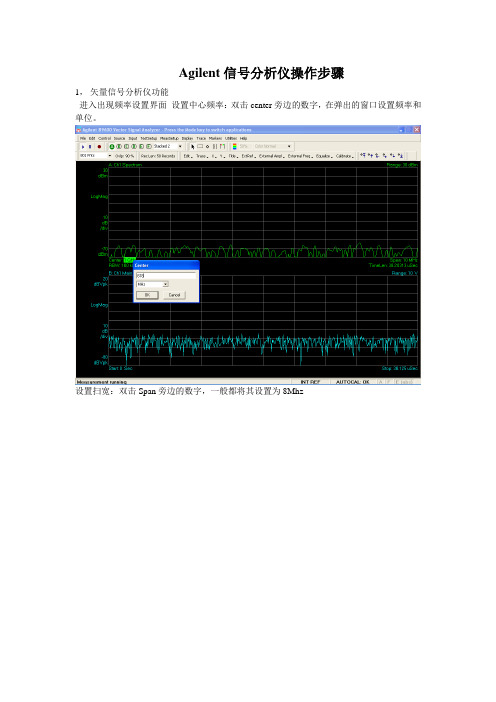
Agilent信号分析仪操作步骤1,矢量信号分析仪功能进入出现频率设置界面设置中心频率:双击center旁边的数字,在弹出的窗口设置频率和单位。
设置扫宽:双击Span旁边的数字,一般都将其设置为8Mhz设置range 单击range旁边的数字按向下键将波形图调至中心位置。
(-20dbm左右)选择菜单中的MeasSetup——Demodulator——Digital Demod。
进入数字信号分析功能。
选择图形个数查看星座图(双击左侧绿色方框,在弹出的对话框中选择constellation)查看I眼图(双击左侧绿色方框,在弹出的对话框中选择I-Eye)查看Q眼图(双击左侧绿色方框,在弹出的对话框中选择Q-Eye)进入扫频仪后界面如下设置起始频率,选择功能键Stop Freq设置终止频率,选择Center Freq设置中心频率。
按控制面板上的SPAN x Scale键出现如下界面,选择功能键Span设置扫宽按控制面板上的AMPTD y Scale键出现如下界面,选择功能键More 1of2选择Y Axis Unit 设置电平的单位。
按控制面板上的Trace Delecter键,选择功能键盘Trace Average后出现平滑的曲线。
按控制面板上的Input/Output键,选择功能键RF Input [AC,50欧],选择75欧。
按控制面板上的BW键,出现如下界面。
分别对RBW和VBW进行设置使曲线接近平滑,建议RBW设置为500-600khz左右,VBW设置为20khz左右,这样兼顾了曲线的平滑与扫频的速度。
按控制面板上的Maker 键后输入频率与单位,设置游标。
按控制面板上的Maker Function后可以选择有一定带宽范围的游标,出现如下界面。
选择功能键Band/Interval Density。
选择功能键Band Adjust调整宽度,如需关闭选择Maker Function Off。
Agilgent 86143B 测试使用指导书
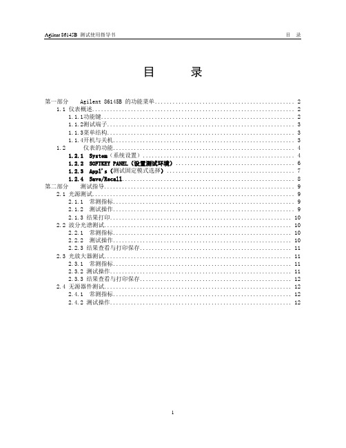
Agilent 86145B 测试使用指导书目录目录第一部分Agilent 86145B 的功能菜单 (2)1.1 仪表概述 (2)1.1.1功能键 (2)1.1.2测试端子 (3)1.1.3菜单结构 (3)1.1.4开机与关机 (3)1.2仪表的功能 (4)1.2.1System(系统设置) (4)1.2.2 SOFTKEY PANEL(设置测试环境) (6)1.2.3 Appl's(测试固定模式选择) (7)1.2.4 Save/Recall (8)第二部分测试指导 (9)2.1 光源测试 (9)2.1.1 常测指标 (9)2.1.2 测试操作 (9)2.1.3 结果打印 (10)2.2 波分光谱测试 (10)2.2.1 常测指标 (10)2.2.2 测试操作 (10)2.2.3 结果查看与打印保存 (11)2.3 光放大器测试 (11)2.3.1 常测指标 (11)2.3.2 测试操作 (11)2.3.3 结果查看与打印保存 (12)2.4 无源器件测试 (12)2.4.1 常测指标 (12)2.4.2 测试操作 (12)第一部分Agilent 86145B 的功能菜单1.1 仪表概述1.1.1功能键图1-1 Agilent 86145B面板示意图上图为Agilent 86145B面板图,主要功能键常用功能简单描述如下:屏幕下方功能键:Auto Meas:自动测试;Auto Align:自动校准,每次测试时,输入一个G.692的标准光,按该键进行自动校准,可以使测试的值更准确可靠;Print:打印;Save/Recall:保存/读取测试设置;System :系统设置(包括波长校准)Appl's:四种常用的测试模式;右方按键:1、屏幕右方有七个空白的按键,是用来选择屏幕上相应位置的选项的;2、数字键及旋钮,是用来输入数字的;3、SOFTKEY PANEL 区五个按键,用来设置测试选项,例如波长范围等等;4、CURSOR 区有滑鼠,可以使用来通过屏幕上的菜单进行设置,它的作用与通过面板上的按键设置有殊途同归之功效。
Agilent高效液相色谱仪标准操作程序
Agilent高效液相色谱仪标准操作程序1.目的:建立一个高效液相色谱的标准操作程序。
2.范围:适用于Agilent高效液相的使用。
3.责任:使用Agilent高效液相的化验员。
4.程序4.1工作环境实验室温度为20~27℃,温度变化<3℃/hr,相对湿度<80%,液相色谱仪工作台,长2米、宽0.8米、承重大于80公斤,离墙距离0.3米以上。
单相交流220V,(+5%~10%),50~60Hz,有单独的良好接地。
配置稳压电源,功率大于2.5千瓦。
4.2使用前的准备4.2.1二次蒸馏水,(建议用0.45微米水相滤膜过滤);甲醇或乙晴(色谱纯),(建议用0.45微米有机相滤膜过滤);其他样品所需流动相,(都需经过0.45微米滤膜过滤)。
将上述溶剂放入超声波池,除去气泡,方可使用。
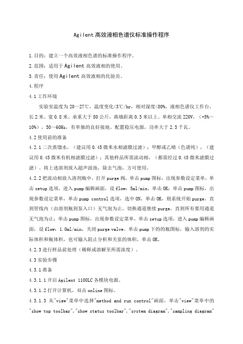
4.2.2把流动相放入溶剂瓶中,打开purge阀,单击pump图标,出现参数设定菜单,单击setup选项,进入pump编辑画面,设flow:5ml/min,单击OK;单击pump图标,出现参数设定菜单,单击pump control选项,选中ON,单击OK,则系统开始purge,直到管线内(由溶剂瓶到泵入口)无气泡为止,切换通道继续purge,直到所有要用通道无气泡为止;单击pump图标,出现参数设定菜单,单击setup选项,进入pump编辑画面,设flow:1.0ml/min,关闭purge valve。
单击pump下的的瓶图标,输入溶剂的实际体积和瓶体积,也可输入阻止分析和关泵的体积,单击OK。
4.2.3进行样品前处理(稀释或溶解至所需浓度)。
4.3实验步骤4.3.1准备4.3.1.1开启Agilent 1100LC各模块电源。
4.3.1.2打开计算机,双击online图标。
4.3.1.3从"view"菜单中选择"method and run control"画面,单击"view"菜单中的"show top toolbar","show status toolbar","system diagram","sampling diagram"使其命令前有"√"标志。
agilent信号分析仪操作步骤.doc
Agilent信号分析仪操作步骤1,矢量信号分析仪功能进入出现频率设置界面设置中心频率:双击center旁边的数字,在弹出的窗口设置频率和单位。
设置扫宽:双击Span旁边的数字,一般都将其设置为8Mhz设置range 单击range旁边的数字按向下键将波形图调至中心位置。
(-20dbm左右)选择菜单中的MeasSetup——Demodulator——Digital Demod。
进入数字信号分析功能。
选择图形个数查看星座图(双击左侧绿色方框,在弹出的对话框中选择constellation)查看I眼图(双击左侧绿色方框,在弹出的对话框中选择I-Eye)查看Q眼图(双击左侧绿色方框,在弹出的对话框中选择Q-Eye)进入扫频仪后界面如下设置起始频率,选择功能键Stop Freq设置终止频率,选择Center Freq设置中心频率。
按控制面板上的SPAN x Scale键出现如下界面,选择功能键Span设置扫宽按控制面板上的AMPTD y Scale键出现如下界面,选择功能键More 1of2选择Y Axis Unit 设置电平的单位。
按控制面板上的Trace Delecter键,选择功能键盘Trace Average后出现平滑的曲线。
按控制面板上的Input/Output键,选择功能键RF Input [AC,50欧],选择75欧。
按控制面板上的BW键,出现如下界面。
分别对RBW和VBW进行设置使曲线接近平滑,建议RBW设置为500-600khz左右,VBW设置为20khz左右,这样兼顾了曲线的平滑与扫频的速度。
按控制面板上的Maker 键后输入频率与单位,设置游标。
按控制面板上的Maker Function后可以选择有一定带宽范围的游标,出现如下界面。
选择功能键Band/Interval Density。
选择功能键Band Adjust调整宽度,如需关闭选择Maker Function Off。
光谱分析仪实验指导书(用)
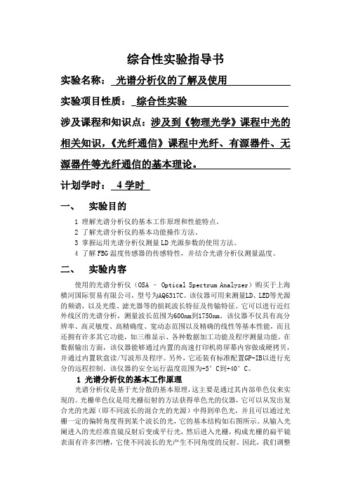
综合性实验指导书实验名称:光谱分析仪的了解及使用综合性实验涉及课程和知识点:涉及到《物理光学》课程中光的相关知识,《光纤通信》课程中光纤、有源器件、无源器件等光纤通信的基本理论。
计划学时:4学时一、实验目的1 理解光谱分析仪的基本工作原理和性能特点。
2 了解光谱分析仪的基本功能操作方法。
3 掌握运用光谱分析仪测量LD光源参数的使用方法。
4 了解FBG温度传感器的传感特性,并结合光谱分析仪测量温度。
二、实验内容使用的光谱分析仪(OSA – Optical Spectrum Analyzer)购买于上海横河国际贸易有限公司,型号为AQ6317C。
该仪器可用来测量LD、LED等光源的频谱,以及光缆、滤光器等的损耗波长特征及传输特征。
它可以进行近红外线区的光谱分析,测量波长范围为600nm到1750nm。
该仪器不仅具有高分辨率、高灵敏度、高精确度、宽动态范围以及精确的线性等基本性能,而且还拥有许多其它功能,如三维显示、各种数据加工功能及程序测量功能。
在数据输出方面,该仪器能够通过内置的高速打印机将屏幕内容做成硬拷贝,并通过内置软盘读/写波形及程序。
另外,它还装有标准配置GP-IB以进行充分的远程控制。
该仪器的安全运行温度范围为+5°C到+40°C。
1 光谱分析仪的基本工作原理光谱分析仪是基于光分散的基本原理,这主要是通过其内部单色仪来实现的。
光栅单色仪是用光栅衍射的方法获得单色光的仪器,它可以从发出复合光的光源(即不同波长的混合光的光源)中得到单色光,并且可以通过光栅一定的偏转角度得到某个波长的光,它的基本结构如右图所示。
从输入光阑进入的光经准直镜反射后变成平行光,然后进入光栅,构成光栅的扁平镜表面有许多凹槽,它使不同波长的光产生不同角度的反射。
因此,我们调整聚焦镜使它只能接收特定角度的反射光。
调整输出光阑到某一确定位置,使聚焦镜的光聚焦到这一位置,这样就只能使某些特定波长成分的光通过输出光阑。
Agilent Technologies PSA 和 ESA 系列光谱分析仪一键测量功能指南说明书
User’s and Programmer’s ReferenceVolume 2One-Button Power Measurements PSA and ESA Series Spectrum Analyzers Refer to Volume 1 for core spectrum analyzer information.This manual provides documentation for the following instruments:Agilent Technologies PSA SeriesE4443A (3 Hz - 6.7 GHz)E4445A (3 Hz - 13.2 GHz)E4440A (3 Hz - 26.5 GHz)E4447A (3 Hz - 42.98 GHz)E4446A (3 Hz - 44.0 GHz)E4448A (3 Hz - 50.0 GHz)Agilent Technologies ESA-E SeriesE4402B (9kHz - 3.0GHz)E4404B (9kHz - 6.7GHz)E4405B (9kHz - 13.2GHz)E4407B (9kHz - 26.5GHz)Agilent Technologies ESA-L SeriesE4411B (9kHz- 1.5GHz)E4403B (9kHz - 3.0GHz)E4408B (9kHz - 26.5GHz)Manufacturing Part Number: E4440-90618Supersedes: E4440-90346Printed in USAMarch 2014© Copyright 1999-2014 Agilent Technologies, Inc..Legal InformationThe information contained in this document is subject to change without notice.Agilent Technologies makes no warranty of any kind with regard to this material, including but not limited to, the implied warranties of merchantability and fitness for a particular purpose. Agilent Technologies shall not be liable for errors contained herein or for incidental or consequential damages in connection with the furnishing, performance, or use of this material.Where to Find the Latest InformationDocumentation is updated periodically.•For the latest information about Agilent Technologies PSA Spectrum Analyzers, including firmware upgrades and application information, please visit the following Internet URL:/find/psa•For the latest information about Agilent Technologies ESA Spectrum Analyzers, including firmware upgrades and application information, please visit the following Internet URL:/find/esa•To receive the latest updates by email, subscribe to Agilent Email Updates:/find/emailupdates•Information on preventing spectrum analyzer damage can be found at:/find/tips21. Using This DocumentAbout the User’s and Programmer’s Information. . . . . . . . . . . . . . . . . . . . . . . . . . . . . . . . . . . . . . . . . . . . . 26 What is in This Book. . . . . . . . . . . . . . . . . . . . . . . . . . . . . . . . . . . . . . . . . . . . . . . . . . . . . . . . . . . . . . . . . 26 Terms Used in This Book . . . . . . . . . . . . . . . . . . . . . . . . . . . . . . . . . . . . . . . . . . . . . . . . . . . . . . . . . . . . . 27 2. One-Button Measurement FunctionsOne - Button Measurement Functions . . . . . . . . . . . . . . . . . . . . . . . . . . . . . . . . . . . . . . . . . . . . . . . . . . . . . 30 Mode Setup (Spectrum Analysis Mode) . . . . . . . . . . . . . . . . . . . . . . . . . . . . . . . . . . . . . . . . . . . . . . . . . . . 33 Radio Std. . . . . . . . . . . . . . . . . . . . . . . . . . . . . . . . . . . . . . . . . . . . . . . . . . . . . . . . . . . . . . . . . . . . . . . . . . 33 Radio Std Setup. . . . . . . . . . . . . . . . . . . . . . . . . . . . . . . . . . . . . . . . . . . . . . . . . . . . . . . . . . . . . . . . . . . . . 45 Retain Params . . . . . . . . . . . . . . . . . . . . . . . . . . . . . . . . . . . . . . . . . . . . . . . . . . . . . . . . . . . . . . . . . . . . . . 47 Enable All Measurements. . . . . . . . . . . . . . . . . . . . . . . . . . . . . . . . . . . . . . . . . . . . . . . . . . . . . . . . . . . . . 47 Autorange of Power Setting (Remote command only). . . . . . . . . . . . . . . . . . . . . . . . . . . . . . . . . . . . . . . 48 MEASURE (Spectrum Analysis Mode) . . . . . . . . . . . . . . . . . . . . . . . . . . . . . . . . . . . . . . . . . . . . . . . . . . . 49 Command Interactions: MEASure, CONFigure, FETCh, INITiate and READ. . . . . . . . . . . . . . . . . . . . 50 Current Measurement Query (Remote Command Only) . . . . . . . . . . . . . . . . . . . . . . . . . . . . . . . . . . . . . 53 Test Current Results Against all Limits (Remote Command Only) . . . . . . . . . . . . . . . . . . . . . . . . . . . . . 53 Meas Off . . . . . . . . . . . . . . . . . . . . . . . . . . . . . . . . . . . . . . . . . . . . . . . . . . . . . . . . . . . . . . . . . . . . . . . . . . 54 Channel Power . . . . . . . . . . . . . . . . . . . . . . . . . . . . . . . . . . . . . . . . . . . . . . . . . . . . . . . . . . . . . . . . . . . . . 54 Occupied BW . . . . . . . . . . . . . . . . . . . . . . . . . . . . . . . . . . . . . . . . . . . . . . . . . . . . . . . . . . . . . . . . . . . . . . 57 Adjacent Channel Power—ACP. . . . . . . . . . . . . . . . . . . . . . . . . . . . . . . . . . . . . . . . . . . . . . . . . . . . . . . . 58 Multi-Carrier Power . . . . . . . . . . . . . . . . . . . . . . . . . . . . . . . . . . . . . . . . . . . . . . . . . . . . . . . . . . . . . . . . . 62 Power Stat CCDF . . . . . . . . . . . . . . . . . . . . . . . . . . . . . . . . . . . . . . . . . . . . . . . . . . . . . . . . . . . . . . . . . . . 64 Harmonic Distortion . . . . . . . . . . . . . . . . . . . . . . . . . . . . . . . . . . . . . . . . . . . . . . . . . . . . . . . . . . . . . . . . . 67 Burst Power . . . . . . . . . . . . . . . . . . . . . . . . . . . . . . . . . . . . . . . . . . . . . . . . . . . . . . . . . . . . . . . . . . . . . . . 70 Intermod (TOI) . . . . . . . . . . . . . . . . . . . . . . . . . . . . . . . . . . . . . . . . . . . . . . . . . . . . . . . . . . . . . . . . . . . . . 73 Spurious Emissions . . . . . . . . . . . . . . . . . . . . . . . . . . . . . . . . . . . . . . . . . . . . . . . . . . . . . . . . . . . . . . . . . 74 Spectrum Emission Mask . . . . . . . . . . . . . . . . . . . . . . . . . . . . . . . . . . . . . . . . . . . . . . . . . . . . . . . . . . . . . 75 Meas Setup (Adjacent Channel Power—ACP) . . . . . . . . . . . . . . . . . . . . . . . . . . . . . . . . . . . . . . . . . . . . . . 83 Avg Number . . . . . . . . . . . . . . . . . . . . . . . . . . . . . . . . . . . . . . . . . . . . . . . . . . . . . . . . . . . . . . . . . . . . . . . 83 Avg Mode . . . . . . . . . . . . . . . . . . . . . . . . . . . . . . . . . . . . . . . . . . . . . . . . . . . . . . . . . . . . . . . . . . . . . . . . . 84 Chan Integ BW . . . . . . . . . . . . . . . . . . . . . . . . . . . . . . . . . . . . . . . . . . . . . . . . . . . . . . . . . . . . . . . . . . . . . 84 Offset/Limits. . . . . . . . . . . . . . . . . . . . . . . . . . . . . . . . . . . . . . . . . . . . . . . . . . . . . . . . . . . . . . . . . . . . . . . 85 Meas Type . . . . . . . . . . . . . . . . . . . . . . . . . . . . . . . . . . . . . . . . . . . . . . . . . . . . . . . . . . . . . . . . . . . . . . . . 89 Optimize Ref Level . . . . . . . . . . . . . . . . . . . . . . . . . . . . . . . . . . . . . . . . . . . . . . . . . . . . . . . . . . . . . . . . . 90 Method . . . . . . . . . . . . . . . . . . . . . . . . . . . . . . . . . . . . . . . . . . . . . . . . . . . . . . . . . . . . . . . . . . . . . . . . . . . 91 Total Pwr Ref . . . . . . . . . . . . . . . . . . . . . . . . . . . . . . . . . . . . . . . . . . . . . . . . . . . . . . . . . . . . . . . . . . . . . . 94 PSD Ref. . . . . . . . . . . . . . . . . . . . . . . . . . . . . . . . . . . . . . . . . . . . . . . . . . . . . . . . . . . . . . . . . . . . . . . . . . . 95 Limit Test . . . . . . . . . . . . . . . . . . . . . . . . . . . . . . . . . . . . . . . . . . . . . . . . . . . . . . . . . . . . . . . . . . . . . . . . . 96 RRC Filter . . . . . . . . . . . . . . . . . . . . . . . . . . . . . . . . . . . . . . . . . . . . . . . . . . . . . . . . . . . . . . . . . . . . . . . . 96 Filter Alpha . . . . . . . . . . . . . . . . . . . . . . . . . . . . . . . . . . . . . . . . . . . . . . . . . . . . . . . . . . . . . . . . . . . . . . . 97 Noise Correction . . . . . . . . . . . . . . . . . . . . . . . . . . . . . . . . . . . . . . . . . . . . . . . . . . . . . . . . . . . . . . . . . . . 97 Trace/View (ACP Measurement) . . . . . . . . . . . . . . . . . . . . . . . . . . . . . . . . . . . . . . . . . . . . . . . . . . . . . . . . . 99 Spectrum . . . . . . . . . . . . . . . . . . . . . . . . . . . . . . . . . . . . . . . . . . . . . . . . . . . . . . . . . . . . . . . . . . . . . . . . . . 99 Bar Graph . . . . . . . . . . . . . . . . . . . . . . . . . . . . . . . . . . . . . . . . . . . . . . . . . . . . . . . . . . . . . . . . . . . . . . . . . 99 Combined . . . . . . . . . . . . . . . . . . . . . . . . . . . . . . . . . . . . . . . . . . . . . . . . . . . . . . . . . . . . . . . . . . . . . . . . 100 Combined View Units. . . . . . . . . . . . . . . . . . . . . . . . . . . . . . . . . . . . . . . . . . . . . . . . . . . . . . . . . . . . . . . 100 Trace . . . . . . . . . . . . . . . . . . . . . . . . . . . . . . . . . . . . . . . . . . . . . . . . . . . . . . . . . . . . . . . . . . . . . . . . . . . . 100 Meas Setup (Burst Power) . . . . . . . . . . . . . . . . . . . . . . . . . . . . . . . . . . . . . . . . . . . . . . . . . . . . . . . . . . . . . 1013Avg Number . . . . . . . . . . . . . . . . . . . . . . . . . . . . . . . . . . . . . . . . . . . . . . . . . . . . . . . . . . . . . . . . . . . . . . 101 Avg Mode . . . . . . . . . . . . . . . . . . . . . . . . . . . . . . . . . . . . . . . . . . . . . . . . . . . . . . . . . . . . . . . . . . . . . . . . 102 Average Type . . . . . . . . . . . . . . . . . . . . . . . . . . . . . . . . . . . . . . . . . . . . . . . . . . . . . . . . . . . . . . . . . . . . . 103 Threshold Lvl . . . . . . . . . . . . . . . . . . . . . . . . . . . . . . . . . . . . . . . . . . . . . . . . . . . . . . . . . . . . . . . . . . . . . 103 Meas Method . . . . . . . . . . . . . . . . . . . . . . . . . . . . . . . . . . . . . . . . . . . . . . . . . . . . . . . . . . . . . . . . . . . . . 104 Burst Width. . . . . . . . . . . . . . . . . . . . . . . . . . . . . . . . . . . . . . . . . . . . . . . . . . . . . . . . . . . . . . . . . . . . . . . 104 Optimize Ref Level. . . . . . . . . . . . . . . . . . . . . . . . . . . . . . . . . . . . . . . . . . . . . . . . . . . . . . . . . . . . . . . . . 106 Trace/View (Burst Power) . . . . . . . . . . . . . . . . . . . . . . . . . . . . . . . . . . . . . . . . . . . . . . . . . . . . . . . . . . . . . 107 RF Envelope. . . . . . . . . . . . . . . . . . . . . . . . . . . . . . . . . . . . . . . . . . . . . . . . . . . . . . . . . . . . . . . . . . . . . . 107 Combined . . . . . . . . . . . . . . . . . . . . . . . . . . . . . . . . . . . . . . . . . . . . . . . . . . . . . . . . . . . . . . . . . . . . . . . . 108 Trace . . . . . . . . . . . . . . . . . . . . . . . . . . . . . . . . . . . . . . . . . . . . . . . . . . . . . . . . . . . . . . . . . . . . . . . . . . . . 108 Meas Setup (Complementary Cumulative Distribution Function—CCDF) . . . . . . . . . . . . . . . . . . . . . . . 109 Meas BW . . . . . . . . . . . . . . . . . . . . . . . . . . . . . . . . . . . . . . . . . . . . . . . . . . . . . . . . . . . . . . . . . . . . . . . . 109 Counts . . . . . . . . . . . . . . . . . . . . . . . . . . . . . . . . . . . . . . . . . . . . . . . . . . . . . . . . . . . . . . . . . . . . . . . . . . 110 Meas Interval . . . . . . . . . . . . . . . . . . . . . . . . . . . . . . . . . . . . . . . . . . . . . . . . . . . . . . . . . . . . . . . . . . . . . 111 Optimize Ref Level . . . . . . . . . . . . . . . . . . . . . . . . . . . . . . . . . . . . . . . . . . . . . . . . . . . . . . . . . . . . . . . . 112 Display (Complementary Cumulative Distribution Function—CCDF). . . . . . . . . . . . . . . . . . . . . . . . . . . 113 Full Screen . . . . . . . . . . . . . . . . . . . . . . . . . . . . . . . . . . . . . . . . . . . . . . . . . . . . . . . . . . . . . . . . . . . . . . . 113 Store Ref Trace. . . . . . . . . . . . . . . . . . . . . . . . . . . . . . . . . . . . . . . . . . . . . . . . . . . . . . . . . . . . . . . . . . . . 113 Ref Trace. . . . . . . . . . . . . . . . . . . . . . . . . . . . . . . . . . . . . . . . . . . . . . . . . . . . . . . . . . . . . . . . . . . . . . . . . 113 Gaussian Trace . . . . . . . . . . . . . . . . . . . . . . . . . . . . . . . . . . . . . . . . . . . . . . . . . . . . . . . . . . . . . . . . . . . . 114 Preferences . . . . . . . . . . . . . . . . . . . . . . . . . . . . . . . . . . . . . . . . . . . . . . . . . . . . . . . . . . . . . . . . . . . . . . . 114 Marker (Complementary Cumulative Distribution Function—CCDF) . . . . . . . . . . . . . . . . . . . . . . . . . . 115 Select Marker . . . . . . . . . . . . . . . . . . . . . . . . . . . . . . . . . . . . . . . . . . . . . . . . . . . . . . . . . . . . . . . . . . . . . 116 Normal . . . . . . . . . . . . . . . . . . . . . . . . . . . . . . . . . . . . . . . . . . . . . . . . . . . . . . . . . . . . . . . . . . . . . . . . . . 116 Delta . . . . . . . . . . . . . . . . . . . . . . . . . . . . . . . . . . . . . . . . . . . . . . . . . . . . . . . . . . . . . . . . . . . . . . . . . . . . 117 Off. . . . . . . . . . . . . . . . . . . . . . . . . . . . . . . . . . . . . . . . . . . . . . . . . . . . . . . . . . . . . . . . . . . . . . . . . . . . . . 117 Marker Trace . . . . . . . . . . . . . . . . . . . . . . . . . . . . . . . . . . . . . . . . . . . . . . . . . . . . . . . . . . . . . . . . . . . . . 118 Marker All Off . . . . . . . . . . . . . . . . . . . . . . . . . . . . . . . . . . . . . . . . . . . . . . . . . . . . . . . . . . . . . . . . . . . . 118 Marker X Position (Remote Command Only) . . . . . . . . . . . . . . . . . . . . . . . . . . . . . . . . . . . . . . . . . . . . 119 Marker Y Position (Remote Command Only) . . . . . . . . . . . . . . . . . . . . . . . . . . . . . . . . . . . . . . . . . . . . 120 Marker Maximum and Minimum (Remote Command Only) . . . . . . . . . . . . . . . . . . . . . . . . . . . . . . . . 120 SPAN X Scale (Complementary Cumulative Distribution Function—CCDF) . . . . . . . . . . . . . . . . . . . . . 121 Scale/Div . . . . . . . . . . . . . . . . . . . . . . . . . . . . . . . . . . . . . . . . . . . . . . . . . . . . . . . . . . . . . . . . . . . . . . . . 121 Meas Setup (Channel Power—CHP) . . . . . . . . . . . . . . . . . . . . . . . . . . . . . . . . . . . . . . . . . . . . . . . . . . . . 123 Avg Number . . . . . . . . . . . . . . . . . . . . . . . . . . . . . . . . . . . . . . . . . . . . . . . . . . . . . . . . . . . . . . . . . . . . . . 123 Avg Mode . . . . . . . . . . . . . . . . . . . . . . . . . . . . . . . . . . . . . . . . . . . . . . . . . . . . . . . . . . . . . . . . . . . . . . . . 124 Integ BW . . . . . . . . . . . . . . . . . . . . . . . . . . . . . . . . . . . . . . . . . . . . . . . . . . . . . . . . . . . . . . . . . . . . . . . . 124 Chan Pwr Span . . . . . . . . . . . . . . . . . . . . . . . . . . . . . . . . . . . . . . . . . . . . . . . . . . . . . . . . . . . . . . . . . . . . 125 PSD Unit (PSA Only Setting). . . . . . . . . . . . . . . . . . . . . . . . . . . . . . . . . . . . . . . . . . . . . . . . . . . . . . . . . 126 Optimize Ref Level . . . . . . . . . . . . . . . . . . . . . . . . . . . . . . . . . . . . . . . . . . . . . . . . . . . . . . . . . . . . . . . . 126 RRC Filter . . . . . . . . . . . . . . . . . . . . . . . . . . . . . . . . . . . . . . . . . . . . . . . . . . . . . . . . . . . . . . . . . . . . . . . 126 Filter Alpha . . . . . . . . . . . . . . . . . . . . . . . . . . . . . . . . . . . . . . . . . . . . . . . . . . . . . . . . . . . . . . . . . . . . . . 128 Meas Setup (Harmonic Distortion) . . . . . . . . . . . . . . . . . . . . . . . . . . . . . . . . . . . . . . . . . . . . . . . . . . . . . . 129 Avg Number . . . . . . . . . . . . . . . . . . . . . . . . . . . . . . . . . . . . . . . . . . . . . . . . . . . . . . . . . . . . . . . . . . . . . . 129 Avg Mode . . . . . . . . . . . . . . . . . . . . . . . . . . . . . . . . . . . . . . . . . . . . . . . . . . . . . . . . . . . . . . . . . . . . . . . . 130 Harmonics . . . . . . . . . . . . . . . . . . . . . . . . . . . . . . . . . . . . . . . . . . . . . . . . . . . . . . . . . . . . . . . . . . . . . . . 130 ST/Harmonic . . . . . . . . . . . . . . . . . . . . . . . . . . . . . . . . . . . . . . . . . . . . . . . . . . . . . . . . . . . . . . . . . . . . . 131 Range Table (On/Off). . . . . . . . . . . . . . . . . . . . . . . . . . . . . . . . . . . . . . . . . . . . . . . . . . . . . . . . . . . . . . . 131 4Range Table . . . . . . . . . . . . . . . . . . . . . . . . . . . . . . . . . . . . . . . . . . . . . . . . . . . . . . . . . . . . . . . . . . . . . . 132 Optimize Ref Level . . . . . . . . . . . . . . . . . . . . . . . . . . . . . . . . . . . . . . . . . . . . . . . . . . . . . . . . . . . . . . . . 138 Trace/View (Channel Power Measurement). . . . . . . . . . . . . . . . . . . . . . . . . . . . . . . . . . . . . . . . . . . . . . . . 139 Spectrum . . . . . . . . . . . . . . . . . . . . . . . . . . . . . . . . . . . . . . . . . . . . . . . . . . . . . . . . . . . . . . . . . . . . . . . . . 139 Combined . . . . . . . . . . . . . . . . . . . . . . . . . . . . . . . . . . . . . . . . . . . . . . . . . . . . . . . . . . . . . . . . . . . . . . . . 139 Trace . . . . . . . . . . . . . . . . . . . . . . . . . . . . . . . . . . . . . . . . . . . . . . . . . . . . . . . . . . . . . . . . . . . . . . . . . . . . 139 Trace/View (Harmonic Distortion). . . . . . . . . . . . . . . . . . . . . . . . . . . . . . . . . . . . . . . . . . . . . . . . . . . . . . . 141 Harmonics . . . . . . . . . . . . . . . . . . . . . . . . . . . . . . . . . . . . . . . . . . . . . . . . . . . . . . . . . . . . . . . . . . . . . . . 141 Harmonics & THD . . . . . . . . . . . . . . . . . . . . . . . . . . . . . . . . . . . . . . . . . . . . . . . . . . . . . . . . . . . . . . . . . 141 Meas Setup (Intermod (TOI)). . . . . . . . . . . . . . . . . . . . . . . . . . . . . . . . . . . . . . . . . . . . . . . . . . . . . . . . . . . 143 Avg Number . . . . . . . . . . . . . . . . . . . . . . . . . . . . . . . . . . . . . . . . . . . . . . . . . . . . . . . . . . . . . . . . . . . . . . 143 Avg Mode . . . . . . . . . . . . . . . . . . . . . . . . . . . . . . . . . . . . . . . . . . . . . . . . . . . . . . . . . . . . . . . . . . . . . . . . 144 TOI Span. . . . . . . . . . . . . . . . . . . . . . . . . . . . . . . . . . . . . . . . . . . . . . . . . . . . . . . . . . . . . . . . . . . . . . . . . 144 Max Mixer Lvl . . . . . . . . . . . . . . . . . . . . . . . . . . . . . . . . . . . . . . . . . . . . . . . . . . . . . . . . . . . . . . . . . . . . 145 Optimize Ref Level. . . . . . . . . . . . . . . . . . . . . . . . . . . . . . . . . . . . . . . . . . . . . . . . . . . . . . . . . . . . . . . . . 146 Meas Setup (Multi-Carrier Power—MCP). . . . . . . . . . . . . . . . . . . . . . . . . . . . . . . . . . . . . . . . . . . . . . . . . 147 Avg Number . . . . . . . . . . . . . . . . . . . . . . . . . . . . . . . . . . . . . . . . . . . . . . . . . . . . . . . . . . . . . . . . . . . . . . 147 Avg Mode . . . . . . . . . . . . . . . . . . . . . . . . . . . . . . . . . . . . . . . . . . . . . . . . . . . . . . . . . . . . . . . . . . . . . . . . 148 Carrier Setup. . . . . . . . . . . . . . . . . . . . . . . . . . . . . . . . . . . . . . . . . . . . . . . . . . . . . . . . . . . . . . . . . . . . . . 149 Offsets/Limits . . . . . . . . . . . . . . . . . . . . . . . . . . . . . . . . . . . . . . . . . . . . . . . . . . . . . . . . . . . . . . . . . . . . . 155 Carrier Result . . . . . . . . . . . . . . . . . . . . . . . . . . . . . . . . . . . . . . . . . . . . . . . . . . . . . . . . . . . . . . . . . . . . . 158 Optimize Ref Level. . . . . . . . . . . . . . . . . . . . . . . . . . . . . . . . . . . . . . . . . . . . . . . . . . . . . . . . . . . . . . . . . 158 Method . . . . . . . . . . . . . . . . . . . . . . . . . . . . . . . . . . . . . . . . . . . . . . . . . . . . . . . . . . . . . . . . . . . . . . . . . . 159 Power Ref . . . . . . . . . . . . . . . . . . . . . . . . . . . . . . . . . . . . . . . . . . . . . . . . . . . . . . . . . . . . . . . . . . . . . . . . 160 Limit Test . . . . . . . . . . . . . . . . . . . . . . . . . . . . . . . . . . . . . . . . . . . . . . . . . . . . . . . . . . . . . . . . . . . . . . . . 160 RRC Filter . . . . . . . . . . . . . . . . . . . . . . . . . . . . . . . . . . . . . . . . . . . . . . . . . . . . . . . . . . . . . . . . . . . . . . . 161 Filter Alpha. . . . . . . . . . . . . . . . . . . . . . . . . . . . . . . . . . . . . . . . . . . . . . . . . . . . . . . . . . . . . . . . . . . . . . . 161 Noise Correction . . . . . . . . . . . . . . . . . . . . . . . . . . . . . . . . . . . . . . . . . . . . . . . . . . . . . . . . . . . . . . . . . . 162 Trace/View (Multi-Carrier Power Measurement). . . . . . . . . . . . . . . . . . . . . . . . . . . . . . . . . . . . . . . . . . . . 163 Spectrum . . . . . . . . . . . . . . . . . . . . . . . . . . . . . . . . . . . . . . . . . . . . . . . . . . . . . . . . . . . . . . . . . . . . . . . . . 163 Combined . . . . . . . . . . . . . . . . . . . . . . . . . . . . . . . . . . . . . . . . . . . . . . . . . . . . . . . . . . . . . . . . . . . . . . . . 163 Combined View Units. . . . . . . . . . . . . . . . . . . . . . . . . . . . . . . . . . . . . . . . . . . . . . . . . . . . . . . . . . . . . . . 164 Trace . . . . . . . . . . . . . . . . . . . . . . . . . . . . . . . . . . . . . . . . . . . . . . . . . . . . . . . . . . . . . . . . . . . . . . . . . . . . 164 Meas Setup (Occupied Bandwidth—OBW) . . . . . . . . . . . . . . . . . . . . . . . . . . . . . . . . . . . . . . . . . . . . . . . 165 Avg Number . . . . . . . . . . . . . . . . . . . . . . . . . . . . . . . . . . . . . . . . . . . . . . . . . . . . . . . . . . . . . . . . . . . . . . 165 Avg Mode . . . . . . . . . . . . . . . . . . . . . . . . . . . . . . . . . . . . . . . . . . . . . . . . . . . . . . . . . . . . . . . . . . . . . . . . 166 Max Hold . . . . . . . . . . . . . . . . . . . . . . . . . . . . . . . . . . . . . . . . . . . . . . . . . . . . . . . . . . . . . . . . . . . . . . . . 166 Occ BW% Pwr . . . . . . . . . . . . . . . . . . . . . . . . . . . . . . . . . . . . . . . . . . . . . . . . . . . . . . . . . . . . . . . . . . . 167 OBW Span . . . . . . . . . . . . . . . . . . . . . . . . . . . . . . . . . . . . . . . . . . . . . . . . . . . . . . . . . . . . . . . . . . . . . . . 167 x dB . . . . . . . . . . . . . . . . . . . . . . . . . . . . . . . . . . . . . . . . . . . . . . . . . . . . . . . . . . . . . . . . . . . . . . . . . . . . 168 Optimize Ref Level . . . . . . . . . . . . . . . . . . . . . . . . . . . . . . . . . . . . . . . . . . . . . . . . . . . . . . . . . . . . . . . . 169 Meas Setup (Spectrum Emissions Mask—SEM) . . . . . . . . . . . . . . . . . . . . . . . . . . . . . . . . . . . . . . . . . . . 171 Avg Number . . . . . . . . . . . . . . . . . . . . . . . . . . . . . . . . . . . . . . . . . . . . . . . . . . . . . . . . . . . . . . . . . . . . . . 171 Meas Type . . . . . . . . . . . . . . . . . . . . . . . . . . . . . . . . . . . . . . . . . . . . . . . . . . . . . . . . . . . . . . . . . . . . . . . 172 Ref Channel . . . . . . . . . . . . . . . . . . . . . . . . . . . . . . . . . . . . . . . . . . . . . . . . . . . . . . . . . . . . . . . . . . . . . . 173 Offset/Limits . . . . . . . . . . . . . . . . . . . . . . . . . . . . . . . . . . . . . . . . . . . . . . . . . . . . . . . . . . . . . . . . . . . . . 175 Results Index (PSA only) . . . . . . . . . . . . . . . . . . . . . . . . . . . . . . . . . . . . . . . . . . . . . . . . . . . . . . . . . . . . 187 Optimize Ref Level. . . . . . . . . . . . . . . . . . . . . . . . . . . . . . . . . . . . . . . . . . . . . . . . . . . . . . . . . . . . . . . . . 187 RRC Filter . . . . . . . . . . . . . . . . . . . . . . . . . . . . . . . . . . . . . . . . . . . . . . . . . . . . . . . . . . . . . . . . . . . . . . . 1875Filter Alpha . . . . . . . . . . . . . . . . . . . . . . . . . . . . . . . . . . . . . . . . . . . . . . . . . . . . . . . . . . . . . . . . . . . . . . 188 Display (Spectrum Emissions Mask—SEM) . . . . . . . . . . . . . . . . . . . . . . . . . . . . . . . . . . . . . . . . . . . . . . 189 Full Screen . . . . . . . . . . . . . . . . . . . . . . . . . . . . . . . . . . . . . . . . . . . . . . . . . . . . . . . . . . . . . . . . . . . . . . . 189 Limit Display . . . . . . . . . . . . . . . . . . . . . . . . . . . . . . . . . . . . . . . . . . . . . . . . . . . . . . . . . . . . . . . . . . . . . 189 Preferences . . . . . . . . . . . . . . . . . . . . . . . . . . . . . . . . . . . . . . . . . . . . . . . . . . . . . . . . . . . . . . . . . . . . . . . 189 Marker (Spectrum Emissions Mask—SEM) . . . . . . . . . . . . . . . . . . . . . . . . . . . . . . . . . . . . . . . . . . . . . . . 191 Select Marker . . . . . . . . . . . . . . . . . . . . . . . . . . . . . . . . . . . . . . . . . . . . . . . . . . . . . . . . . . . . . . . . . . . . . 191 Normal . . . . . . . . . . . . . . . . . . . . . . . . . . . . . . . . . . . . . . . . . . . . . . . . . . . . . . . . . . . . . . . . . . . . . . . . . . 192 Off. . . . . . . . . . . . . . . . . . . . . . . . . . . . . . . . . . . . . . . . . . . . . . . . . . . . . . . . . . . . . . . . . . . . . . . . . . . . . . 192 Trace/View (Spectrum Emissions Mask). . . . . . . . . . . . . . . . . . . . . . . . . . . . . . . . . . . . . . . . . . . . . . . . . . 193 Abs Pwr & Freq . . . . . . . . . . . . . . . . . . . . . . . . . . . . . . . . . . . . . . . . . . . . . . . . . . . . . . . . . . . . . . . . . . . 193 Rel Pwr & Freq . . . . . . . . . . . . . . . . . . . . . . . . . . . . . . . . . . . . . . . . . . . . . . . . . . . . . . . . . . . . . . . . . . . 193 Integrated Power. . . . . . . . . . . . . . . . . . . . . . . . . . . . . . . . . . . . . . . . . . . . . . . . . . . . . . . . . . . . . . . . . . . 194 SPAN X Scale (Spectrum Emissions Mask—SEM) . . . . . . . . . . . . . . . . . . . . . . . . . . . . . . . . . . . . . . . . . 195 Scale/Div. . . . . . . . . . . . . . . . . . . . . . . . . . . . . . . . . . . . . . . . . . . . . . . . . . . . . . . . . . . . . . . . . . . . . . . . . 195 Ref Value. . . . . . . . . . . . . . . . . . . . . . . . . . . . . . . . . . . . . . . . . . . . . . . . . . . . . . . . . . . . . . . . . . . . . . . . . 195 Ref Position. . . . . . . . . . . . . . . . . . . . . . . . . . . . . . . . . . . . . . . . . . . . . . . . . . . . . . . . . . . . . . . . . . . . . . . 196 Meas Setup (Spurious Emissions) . . . . . . . . . . . . . . . . . . . . . . . . . . . . . . . . . . . . . . . . . . . . . . . . . . . . . . . 197 Avg Number . . . . . . . . . . . . . . . . . . . . . . . . . . . . . . . . . . . . . . . . . . . . . . . . . . . . . . . . . . . . . . . . . . . . . . 197 Avg Mode . . . . . . . . . . . . . . . . . . . . . . . . . . . . . . . . . . . . . . . . . . . . . . . . . . . . . . . . . . . . . . . . . . . . . . . . 197 Range Table . . . . . . . . . . . . . . . . . . . . . . . . . . . . . . . . . . . . . . . . . . . . . . . . . . . . . . . . . . . . . . . . . . . . . . 198 Meas Type . . . . . . . . . . . . . . . . . . . . . . . . . . . . . . . . . . . . . . . . . . . . . . . . . . . . . . . . . . . . . . . . . . . . . . . 211 Spur . . . . . . . . . . . . . . . . . . . . . . . . . . . . . . . . . . . . . . . . . . . . . . . . . . . . . . . . . . . . . . . . . . . . . . . . . . . . 212 Ref Level . . . . . . . . . . . . . . . . . . . . . . . . . . . . . . . . . . . . . . . . . . . . . . . . . . . . . . . . . . . . . . . . . . . . . . . . 213 Fast Spurious Meas . . . . . . . . . . . . . . . . . . . . . . . . . . . . . . . . . . . . . . . . . . . . . . . . . . . . . . . . . . . . . . . . 213 Display (Spurious Emissions) for PSA Only. . . . . . . . . . . . . . . . . . . . . . . . . . . . . . . . . . . . . . . . . . . . . . . 215 Full Screen . . . . . . . . . . . . . . . . . . . . . . . . . . . . . . . . . . . . . . . . . . . . . . . . . . . . . . . . . . . . . . . . . . . . . . . 215 Preferences . . . . . . . . . . . . . . . . . . . . . . . . . . . . . . . . . . . . . . . . . . . . . . . . . . . . . . . . . . . . . . . . . . . . . . . 215 Marker (Spurious Emissions) for PSA Only . . . . . . . . . . . . . . . . . . . . . . . . . . . . . . . . . . . . . . . . . . . . . . . 217 Select Marker . . . . . . . . . . . . . . . . . . . . . . . . . . . . . . . . . . . . . . . . . . . . . . . . . . . . . . . . . . . . . . . . . . . . . 217 Normal . . . . . . . . . . . . . . . . . . . . . . . . . . . . . . . . . . . . . . . . . . . . . . . . . . . . . . . . . . . . . . . . . . . . . . . . . . 218 Delta . . . . . . . . . . . . . . . . . . . . . . . . . . . . . . . . . . . . . . . . . . . . . . . . . . . . . . . . . . . . . . . . . . . . . . . . . . . . 218 Off. . . . . . . . . . . . . . . . . . . . . . . . . . . . . . . . . . . . . . . . . . . . . . . . . . . . . . . . . . . . . . . . . . . . . . . . . . . . . . 219 Markers All Off. . . . . . . . . . . . . . . . . . . . . . . . . . . . . . . . . . . . . . . . . . . . . . . . . . . . . . . . . . . . . . . . . . . . 219 Marker Mode . . . . . . . . . . . . . . . . . . . . . . . . . . . . . . . . . . . . . . . . . . . . . . . . . . . . . . . . . . . . . . . . . . . . . 220 3. Menu Maps:One-Button Measurement FunctionsOne-Button Measurement Menu Maps . . . . . . . . . . . . . . . . . . . . . . . . . . . . . . . . . . . . . . . . . . . . . . . . . . . 222 Directions for Use . . . . . . . . . . . . . . . . . . . . . . . . . . . . . . . . . . . . . . . . . . . . . . . . . . . . . . . . . . . . . . . . . 223 MEASURE Key . . . . . . . . . . . . . . . . . . . . . . . . . . . . . . . . . . . . . . . . . . . . . . . . . . . . . . . . . . . . . . . . . . . 224 Meas Control Key . . . . . . . . . . . . . . . . . . . . . . . . . . . . . . . . . . . . . . . . . . . . . . . . . . . . . . . . . . . . . . . . . 225 Mode Setup Key for ESA . . . . . . . . . . . . . . . . . . . . . . . . . . . . . . . . . . . . . . . . . . . . . . . . . . . . . . . . . . . 226 Mode Setup Key for PSA (1 of 3) . . . . . . . . . . . . . . . . . . . . . . . . . . . . . . . . . . . . . . . . . . . . . . . . . . . . . 227 Mode Setup Key for PSA (2 of 3) . . . . . . . . . . . . . . . . . . . . . . . . . . . . . . . . . . . . . . . . . . . . . . . . . . . . . 228 Mode Setup Key for PSA (3 of 3) . . . . . . . . . . . . . . . . . . . . . . . . . . . . . . . . . . . . . . . . . . . . . . . . . . . . . 229 ACP Measurement: Meas Setup Key . . . . . . . . . . . . . . . . . . . . . . . . . . . . . . . . . . . . . . . . . . . . . . . . . . 230 ACP Measurement: Trace/View Key . . . . . . . . . . . . . . . . . . . . . . . . . . . . . . . . . . . . . . . . . . . . . . . . . . . 231 Burst Power Measurement: Meas Setup Key . . . . . . . . . . . . . . . . . . . . . . . . . . . . . . . . . . . . . . . . . . . . 232 6。
Agilent 8614X光谱分析仪波长校准命令
Wavelength Calibrationfor the 8614X SeriesOptical Spectrum Analyzers Product Note 86140-2Internal WavelengthCalibrationManual method using the internal calibrator 1. Access the EWC setup panel:System > More System Functions... > Service Menu... > Adv Service Functions > More Adv Service Menu > Enhanced Wvl Cal Setup 2. Enable the function, if necessary, and select the desired calibration range.3. Clean all connectors and connect the internal calibrator to the OSA input.4. Access the Wavelength Calibration setup panel:System > Calibration... > Wavelength Cal Setup... 5. Set the signal source to Calibrator.6. Select Perform Calibration.Remote method using the internal calibrator CALibration:WAVelength:EWC:FUNCtion ON !Enable enhanced wavelength calibration.CALibration:WAVelength:EWC:RANGe TELE !Select telecom (1270-1670) nm range for !enhanced wavelength calibration.CALibration:WAVelength:INT ernal:NORMal !Perform internal wavelength calibration. !The internal calibrator must be connected !before sending this ing an external single-point calibration source allows the calibration to be done at a specific wavelength. This single wavelength user cali-bration can be repeated as often as necessary to correct for environ-mental variations, and existing multipoint wavelength offsets will be adjusted accordingly. After a single wavelength calibration, wavelength accuracy will be ±10 pm within 10 nm of the reference signal.The Enhanced Wavelength Calibration (EWC) process can also be used to increase the accuracy of the single-point calibration.Manual method using an external source1. Connect the external source to the OSA input.2. Auto align the OSA to the input signal.3. Access the Wavelength Calibration setup panel:System > Calibration... > Wavelength Cal Setup...4. Select Air or Vacuum reference for the signal source.5. Set the signal source to External.6. Select the desired Calibration Wavelength. This wavelength must be within ±2.5 nm of the source wavelength.7. Select Perform Calibration.Remote method using an external source• For a source with a single peak:CALibration:WAVelength:VALue <param>!Set calibration wavelengthCALibration:WAVelength !Calibrate signal at wavelength • For a source with multiple peaks:CALibration:WAVelength:VALue <param>!Set calibration wavelengthCALCulate:MARKer[1|2|3|4]:X:WAVelength <param>!Set marker wavelengthCALibration:WAVelength:MARKer !Calibrate signal at markerExternal Single Wavelength CalibrationAn external multipoint wavelength calibration can be performed overany specified wavelength range, up to and including the full wavelengthrange of the OSA (600 nm to 1700 nm). Narrow measurement spanscan be chosen to provide greater accuracy over a selected range.Calibrating the wavelength every 10 nm within the desired wavelengthrange is usually sufficient to improve wavelength accuracy. After amultipoint wavelength calibration, wavelength accuracy will be ±10 pmwithin 10 nm of each calibration wavelength. If using an 8614xA thathas been upgraded to 8614xB firmware, typical accuracy will be ±25 pm.Using the following remote procedure, a signal is sent from a tunablelaser source into a multi-wavelength meter and the OSA simultaneously.After measuring the wavelength of the input signal on both instru-ments, the two values are compared. Taking the multi-wavelengthmeter readings as actual, the software calculates the error offsets at each wavelength using the equation:WL Error = (OSA indicated WL) - (multi-wavelength meter actual WL)This procedure is repeated over the entire wavelength range. Thedata is averaged over narrow wavelength spans to provide a suitablecorrection for each span. The example below demonstrates thistechnique.Once the instrument is calibrated, the new wavelength accuracy canbe maintained for many hours without recalibration, assuming astable temperature environment.Tip:If the OSA is turned off, the multipoint data will be retained atthe next power-on, but the internal thermal shift can introduceinaccuracies to the calibration data. To help compensate for this, asingle point calibration using the Offset feature in the WavelengthCalibration Setup panel can be used to adjust the multipoint data.Access this feature by selecting System > Calibration... > WavelengthCal Setup... and choosing the Offset option before running the singlepoint calibration. To insure this offset process has provided sufficientaccuracy, the wavelength readings of the multi-wavelength meter andthe OSA should be compared to verify the wavelength accuracy anddetermine if a full multipoint wavelength recalibration is necessary.ExampleIn this example, the sampling is done over 2 nm spans using atunable laser source stepped every 100 pm and measured by the OSAand the multi-wavelength meter. These spans are taken every 10 nmover the desired calibration range. For example, if you are measuringfrom 1500 nm to 1600 nm, you might sample from 1509-1511 nm in100 pm steps, then move to 1519-1521 nm, and so on. Sampling overa 100 nm span with these parameters usually takes about 25 minutes.Each 2 nm span generates a set of points. For each such set, a wave-length offset pair is determined. The average of the minimum errorand the maximum error is calculated to determine the necessaryoffset. This average is applied to the wavelength located at the midpointof the two extremes.External Multipoint Wavelength CalibrationFigure 1. T est setup of the OSA, PC, tunable laser source, multi-wavelength meter and cables 1. Write a program in a language appropriate for your test station. The following programming example in HP Basic has been provided as a guide to the sequence of commands necessary to perform an external wavelength calibration.2. Connect the equipment as in Figure 1. This example uses an Agilent 86120C multi-wavelength meter and an Agilent 8164A/81640A tunable laser source.3. After warm-up and environmental stabilization, and just before beginning the multipoint calibration, perform a manual, external wavelength calibration using the Replaced option in the Wavelength Calibration Setup panel. If there is no existing multipoint data to replace, this option will be grayed out. The TLS can be used as the source and the multi-wavelength meter will indicate the external calibration wavelength value.4. The program sets up and runs the calibration as follows:a. The OSA is placed into a high performance state, setting thefollowing parameters:Resolution bandwidth - 0.06 nm for the 86142 or 86145 OSA,0.07 nm for the 86140, 86141 or 86143 OSA.Video bandwidth - narrowest possible for your setup.Sweep time - Auto.Wavelength span - as appropriate for your setup.Trace points - as appropriate for your setup.b. The auto-align routine is run on the OSA.c. Any existing multipoint calibration data is disabled so it doesnot interfere with collecting new data.d. The tunable laser source is stepped from wavelength-to-wavelength.e. At each point, the wavelength is measured by both the multi-wavelength meter and the OSA. The output power and settling time of the tunable laser source varies from instrument toinstrument so the multi-wavelength meter reading is taken both before and after the OSA reading to verify the tunable lasersource stability within ±1 pm.f. Various checks are performed to insure valid data:• To verify a real signal is present, the 3 dB bandwidth of thesignal at the OSA must be less than full span and the peakamplitude must be above –70 dBm.• To verify the minimum 2 pm spacing required for validcorrection data, the TLS wavelength steps are checked asmeasured by the multi-wavelength meter.• The slope of the correction data is checked to be less than 1and greater than –1. For example, a correction of –8 pm at1550 nm, followed by a correction of +100 pm at 1550.1 nmwould be a slope of 108pm/100pm which is not allowed.• The magnitude of the correction is checked to be less than 200 pm.g. The values are compared and the wavelength errors calculated.h. A correction string is generated from this data.i. The correction string is sent to the OSA and applied to futurewavelength measurements.Yn are wavelength errors in vacuum (indicated wavelength - actualwavelength) in meters. Yn magnitude must be less than 200 pm.The spacing between data points must be larger than the magnitude ofthe change in error between data points. Specifically, the magnitude of theslope must be less than 1. Where slope = (Y(n+1) - Y(n))/(X(n+1)-X(n)).For example if Xn are 10 pm apart, Yn must change by less than 10 pm.The query returns any external multipoint wavelength calibrationdata in string format. For example:+1.45011471E-006,+0.00000000E+000,+1.50011168E-006,+9.20199449E-13,+1.56010779E-006,-1.12468277E-012,+1.61010432E-006,+0.00000000E+000Previous multipoint wavelength data are cleared each time thecommand is used. Therefore, to modify the multipoint wavelengthcalibration data, use the query to obtain the existing table of data,then make changes to the table and reenter it using this command.When measuring new external multipoint calibration data, use“CALibration:WAVelength:MODE:NORMal” to disable previous wave-length calibration data.CALibration:WAVelength:MULTipoint:DELeteDeletes calibration data entered byCALibration:WAVelength:MULTipoint:DATA.CALibration:WAVelength:USER:DATA <string>CALibration:WAVelength:USER:DATA?Although this command is available, some OSA firmware versions donot support it. In place of this command, it is recommended that youuse: CALibration:WAVelength:MULTipoint:DATA.All information given for CALibration:WAVelength:MULTipoint:DATAwill apply to this command.Sample ProgramThe following is a sample user calibration program written in HPBASIC for Windows using the Agilent 8168 tunable laser source andthe 86120C multi-wavelength meter.10!INITIALIZE VARIABLES20!Variable definition: This example sets up a calibration point every 10 nm (Cal_inc),30!starting at 1530 nm (Start_wl) and ending at 1560 nm (Stop_wl). Wavelength offsets are40!measured over a 2nm range (Cal_span) taken every 0.1 nm (Cal_wl_inc) centered at the50!calibration wavelengths (1530, 1540, 1550, and 1560). The maximum and minimum offsets60!are then averaged, and the result is entered as the offset for the center wavelength.70!80!This example program will also set a zero offset at the wavelengths +Cal_inc from the90!Stop_wl, and -Cal_inc from the Start_wl, if Cal_inc is at least 0.2nm. If Cal_inc is less than 0.2nm,100 !a zero will be entered 0.2nm before the start and after the stop wavelengths.110 !For this example, a zero offset is entered at 1520 and 1570nm. The OSA interpolates120 !offset wavelengths between those entered in the calibration procedure. Inserting zeroes130 !at either end of the calibration string ensures that offsets are zeroed outside the calibration region.140 !150 !*********************************Program Start**********************************160 !170 !*****************************Global Variable Declaration****************************180 !190 Start_wl=1530 !Start WL, nm200 Stop_wl=1560 !Stop WL, nm210 Cal_inc=10 !Calibration increment, nm220 Cal_span=2 !Calibration span, nm230 Sweep_span=.4 !Sweep span used when taking data, nm 240 Cal_wl_inc=0.1 !Calibration wavelength increment, nm 250 DIM Wl_cal_string$[32767] !Initialize string to store cal offsets260 DIM New_cal_string$[32767] !Initialize temporary string270 Infinity=999999999 !Variable for maximum offset280 Not_a_number=9.91E+37 !SCPI definition for undefined values 290 Offset=0 !Initialize offset300 Offset_wl=(Start_wl-(Cal_span/2)-.2)*E-9 !Initialize offset wl for slope check310 !320 !*******************************************************************************330 !The following check ensures that the calibration points are not within 2 pm of one another.340 !This is the lower limit for calibration point spacing in the OSA350 !*******************************************************************************360 !370 IF Cal_span>(Cal_inc-.002) THEN380 PRINT “Cal_inc must be at least 2 pm larger than Cal_span. Stopping Program”390 GOTO 2150 !Go to end of program400 END IF410 !420 !430 !**************************Initialize Multiwavelength Meter**************************440 CLEAR 720450 ASSIGN @Mwm TO 720460 OUTPUT @Mwm;”*RST” !Reset multiwavelength meter470 OUTPUT @Mwm;”SENS:CORR:MED VAC” !Display WL in Vacuum480 !490 !***************************InitializeTunable Laser Source****************************500 CLEAR 724510ASSIGN @Tls TO 724520 OUTPUT @Tls;”*RST” !Reset TLS530 OUTPUT @Tls;”POW:UNIT DBM” !Set power units to DBM540 OUTPUT @Tls;”POW -11DBM” !Set output power to -11DBM550 OUTPUT @Tls;”OUTP ON” !Turn output on560 OUTPUT @Tls;”SOUR:WAV “&VAL$(Start_wl)&”nm” !Set output wl to mid range570 !580 !*******************Initialize OSA and Set to High Performance State*********************590 CLEAR 723600 ASSIGN @Osa TO 723;EOL CHR$(10) END !Set terminating character to LF w/ EOI 610 OUTPUT @Osa;”*RST” !Reset OSA620 OUTPUT @Osa;”SWE:POIN 401” !Set # of trace points to 401630 OUTPUT @Osa;”SENS:CORR:RVEL:MED VAC” !Display WL in VAC640 OUTPUT @Osa;”SENS:WAV:SPAN “&VAL$(Sweep_span)&”NM”!Set span650 OUTPUT @Osa;”SWE:TIME:AUTO ON” !Set sweep time to auto660 OUTPUT @Osa;”SENS:BAND:VID 194HZ” !Set video bandwidth to 194HZ670 OUTPUT @Osa;”SENS:BAND 0.06NM” !Set resolution bandwidth to 0.06nm 680 OUTPUT @Osa;”CALC:MARK1:TRAC TRA” !Marker on trace A690 OUTPUT @Osa;”CALC:MARK1:FUNC:BAND ON” !Turn on bandwidth marker700 OUTPUT @Osa;”DISP:WIND:TRAC:Y:SCAL:RLEV -20DBM” !Set reference level to -20DBM710 OUTPUT @Osa;”CAL:WAV:MODE NORM” !Turn off any existing multipoint data 720 OUTPUT @Osa;”SENS:WAV:CENT “&VAL$(Start_wl)&”NM” !Set center wl for auto align730 OUTPUT @Osa;”INIT:IMM” !Take a sweep740 OUTPUT @Osa;”CALC:MARK1:MAX” !Mark Peak WL750 OUTPUT @Osa;”CAL:ALIG:MARK1” !Perform Auto Align on TLS Signal 760 !770 !*******************************Measurement Loops*******************************780 !790 !*********************************Outer FOR Loop*********************************800 !Steps the calibration wavelength (Cal_wl) from the start wavelength (Start_wl) to the stop810 ! wavelength (Stop_wl) in increments of the calibration increment (Cal_inc).820 !830 FOR Cal_wl=Start_wl TO Stop_wl STEP Cal_inc840 !Variable declaration850 Max_offset=-Infinity !Initialize maximum offset860 Min_offset=Infinity !Initialize minimum offset870 Max_wl=0 !Set wl of maximum offset to zero 880 Min_wl=0 !Set wl of minimum offset to zero890 !900 !*********************************Inner FOR Loop*********************************910 !Sets the wavelength to be measured in steps of the calibration wavelength (Cal_wl_inc) for the920 !calibration span (cal_span) around the calibration wavelength (Cal_wl).930 !940 !950 FOR Current_wl=Cal_wl-Cal_span/2 TO Cal_wl+Cal_span/2 STEP Cal_wl_inc960!970!****************************Set TLS Output Wavelength***************************980!990OUTPUT @Tls;”SOUR:WAVE “&VAL$(Current_wl)&”NM” !Set TLS output to current wl1000 OUTPUT @Tls;”*OPC?” !Wait for TLS to settle1010 ENTER @Tls;Done1020 !1030 !**********************Initialize Variables for Mode-Hop Check**********************1040 Mwm_wavelength1=-Infinity1050 Mwm_wavelength2=Infinity1060 !1070 !*****************************Mode-Hop Check Loop*****************************1080 !The following loop ensures that the laser is not mode-hopping, by checking1090 !the laser wavelength with the multiwavelength meter before and after the1100 !OSA measurement. The two multiwavelength meter readings must agree within1110 !1.0 pm for the reading to be accepted.1120 !1130 WHILE (ABS(Mwm_wavelength1-Mwm_wavelength2)>1.E-12)1140 !1150 !************************First Multiwavelength Meter Read************************1160 OUTPUT @Mwm;”INIT:IMM;*OPC?” !Take reading and wait to complete 1170 ENTER @Mwm;Done1180 OUTPUT @Mwm;”FETC:SCAL:POW:WAV?” !Query maximum wavelength 1190 ENTER @Mwm;Mwm_wavelength11200 !1210 !********************************Read with OSA********************************1220 !1230 OUTPUT @Osa;”WAV:CENT “&VAL$(Current_wl)&”NM” !Set center wl to the current wl 1240 OUTPUT @Osa;”INIT:IMM” !Take sweep1250 OUTPUT @Osa;”CALC:MARK1:MAX” !Mark peak wavelength1260 OUTPUT @Osa;”CALC:MARK1:FUNC:BAND:RES?” !Query BW 3dB points1270 ENTER @Osa;Osa_bw1280 OUTPUT @Osa;”CALC:MARK1:Y?” !Query peak amplitude1290 ENTER @Osa;Osa_peak1300 IF ((Osa_bw<Not_a_number) AND (Osa_peak>-70)) THEN1310 OUTPUT @Osa;”CALC:MARK1:FUNC:BAND:X:CENT?” !Query wl at mean of 3dB points 1320 ENTER @Osa;Osa_wavelength !Store value as Osa_wavelength 1330 ELSE1340 PRINT “Signal not found at “&VAL$(Current_wl)&” nm”1350 GOTO 16001360 END IF1370 !1380 !***********************Second Multiwavelength Meter Read***********************1390 OUTPUT @Mwm;”INIT:IMM;*OPC?” !Take reading and wait to complete 1400 ENTER @Mwm;Done1410 OUTPUT @Mwm;”FETC:SCAL:POW:WAV?” !Query maximum wavelength 1420 ENTER @Mwm;Mwm_wavelength21430 !1440 END WHILE !End of mode-hop check loop 1450 !1460 !******Find the Wavelength Calibration Offset for the OSA at the Current Wavelength******1470 Mwm_wavelength=(Mwm_wavelength1+Mwm_wavelength2)/21480 Difference=Osa_wavelength-Mwm_wavelength1490 !1500 !************Update Maximum and Minimum Offsets Within Calibration Span************1510 IF Difference>Max_offset THEN1520 Max_offset=Difference !Store max offset1530 Max_wl=Mwm_wavelength !Store wavelength of max offset 1540 END IF1550 IF Difference<Min_offset THEN1560 Min_offset=Difference !Store min offset1570 Min_wl=Mwm_wavelength !Store wavelength of min offset 1580 END IF1590 !1600 NEXT Current_wl !End of inner FOR loop1610 !1620 !**********************Store Previous Offset Pair for Slope Check**********************1630 Last_offset_wl=Offset_wl1640 Last_offset=Offset1650 !1660 !*********************Find Offset Pair for Current Calibration Span*********************1670 Offset_wl=(Max_wl+Min_wl)/21680 Offset=(Max_offset+Min_offset)/21690 !1700 !************************Check Slope and Offset Against Limits*************************1710 IF (Offset_wl>Last_offset_wl) THEN1720 Slope=(Offset-Last_offset)/(Offset_wl-Last_offset_wl)1730 ELSE1740 Slope=Infinity1750 END IF1760 IF ((ABS(Offset)<2.00E-10) AND (ABS(Slope)<=1)) THEN1770 New_cal_string$=New_cal_string$&VAL$(Offset_wl)&”,”&VAL$(Offset)&”,”1780 ELSE1790 PRINT “Calibration Point at: “&VAL$(Cal_wl)&” nm correction value unreasonable, point ignored”1800 END IF1810 !1820 NEXT Cal_wl !End of outer FOR loop1830 !1840 !******************************Build Calibration String******************************1850 !The following builds the calibration string with an initial and a final zero offset from the1860 !first and final calibration wavelengths for interpolation outside the range. The offsets are1870 !entered at least 0.2 nm from the neighboring calibration wavelengths to avoid a possible slope1880 !violation (the largest offset allowed is 0.2 nm). If the Cal_inc spacing is larger than 0.2 nm1890 !the zeroes are entered into cal_inc from the start and stop wavelengths1900 !1910 IF Cal_inc>.2 THEN1920 Wl_cal_string$=VAL$(Start_wl-Cal_inc)&”e-9,0,” !Initialize String w/ first zero offset 1930 Wl_cal_string$=Wl_cal_string$&New_cal_string$ !Append new calibration offset data 1940 Wl_cal_string$=Wl_cal_string$&VAL$(Stop_wl+Cal_inc)&”e-9,0” !Append final zero offset1950 ELSE1960 Wl_cal_string$=VAL$(Start_wl-.2)&”e-9,0,” !Initialize string w/ first zero offset 1970 Wl_cal_string$=Wl_cal_string$&New_cal_string$ !Append new calibration offset data 1980 Wl_cal_string$=Wl_cal_string$&VAL$(Stop_wl+.2)&”e-9,0” !Append final zero offset1990 END IF2000 !2010 !**************************Load Calibration String Into OSA**************************2020 !2030 OUTPUT @Osa;”CAL:WAV:MULT:DATA “;Wl_cal_string$2040 OUTPUT @Osa;”CAL:WAV:MULT:DATA?”2050 DIM Wl_cal_check$[32767]2060 ENTER @Osa;Wl_cal_check$2070 PRINT “WAVELENGTH CALIBRATION STRING=”&Wl_cal_string$2080 PRINT “OSA CALIBRATION SETTINGS=”&Wl_cal_check$2090 !2100 !***********************************Cleanup*************************************2110 OUTPUT @Tls;”OUTP OFF” !Turn off laser2120 LOCAL @Osa !Release remote control2130 LOCAL @Mwm2140 LOCAL @Tls2150 ENDAgilent Technologies’Test and Measurement Support, Services, and AssistanceAgilent Technologies aims to maximize the value you receive, while minimizing your risk and problems. We strive to ensure that you get the test and measurement capabilities you paid for and obtain the support you need. Our extensive support resources and services can help you choose the right Agilent products for your applications and apply them successfully. Every instrument and system we sell has a global warranty. Support is available for at least five years beyond the production life of the product. Two concepts underlie Agilent’s overall support policy: “Our Promise” and “Your Advantage.”Our PromiseOur Promise means your Agilent test and measurement equipment will meet its advertised performance and functionality. When you are choosing new equipment, we will help you with product information, including realistic performance specifications and practical recommendations from experienced test engineers. When you use Agilent equipment, we can verify that it works properly, help with product operation, and provide basic measurement assistance for the use of specified capabilities, at no extra cost upon request. Many self-help tools are available.Your AdvantageYour Advantage means that Agilent offers a wide range of additional expert test and measurement services, which you can purchase according to your unique technical and business needs. Solve problems efficiently and gain a competitive edge by contracting with us for calibration, extra-cost upgrades, out-of-warranty repairs, and on-site education and training, as well as design, system integration, project management, and other professional engineering services. Experienced Agilent engineers and technicians worldwide can help you maximize your productivity, optimize the return on investment of your Agilent instruments and systems, and obtain dependable measurement accuracy for the life of those products.By internet, phone, or fax, get assistance with all your test & measurement needs.Online assistance:/comms/lightwavePhone or FaxUnited States:(tel) 1 800 452 4844Canada:(tel) 1 877 894 4414(fax) (905) 282 6495Europe:(tel) (31 20) 547 2323(fax) (31 20) 547 2390Japan:(tel) (81) 426 56 7832(fax) (81) 426 56 7840Latin America:(tel) (305) 269 7500(fax) (305) 269 7599Australia:(tel) 1 800 629 485(fax) (61 3) 9210 5947New Zealand:(tel) 0 800 738 378(fax) 64 4 495 8950Asia Pacific:(tel) (852) 3197 7777(fax) (852) 2506 9284Product specifications and descriptions in this document subject to change without notice.Copyright © 2000, 2001 Agilent TechnologiesPrinted in USA May 15, 20015980-0043E。
光谱分析仪使用方法说明书

光谱分析仪使用方法说明书一、引言光谱分析仪是一种用于测量物质吸收、发射或散射光谱的仪器,广泛应用于化学、生物、材料科学等领域。
本说明书旨在详细介绍光谱分析仪的使用方法,帮助用户正确、高效地操作该仪器。
二、仪器概述光谱分析仪采用先进的光学系统和检测器件,可实现高精度的光谱测量。
仪器包含以下主要部件:1. 光源:用于发射特定波长的光线,常见的光源包括白炽灯、氘灯、氙灯等。
2. 光栅:通过光栅的衍射效应,将入射光线分解成不同波长的光谱。
3. 样品室:放置待测样品的空间,保证样品与光线的正常相互作用。
4. 检测器:用于接收、测量样品发射或吸收的光信号,并将其转换为电信号。
5. 控制系统:包括光学系统、电子系统以及数据处理和显示系统等,用于操作和控制整个仪器。
三、仪器准备在使用光谱分析仪之前,请按照以下步骤进行仪器准备:1. 安装:将光谱分析仪稳定地安装在干净、稳定的工作台上,并保证充足的通风和周围环境的干净。
2. 电源连接:将仪器的电源线连接到稳定的电源插座,并确保电压符合仪器要求。
3. 光源检查:检查光源的正常工作情况,确保光线稳定且光谱范围符合实验要求。
4. 校准:根据仪器要求,进行必要的校准步骤,以确保测量结果的准确性。
四、样品准备在进行光谱分析之前,需要准备好样品,并按照以下步骤进行处理:1. 样品选择:根据实验要求,选择合适的样品进行分析,并清洁样品以确保无杂质影响分析结果。
2. 样品装载:将清洁的样品放置于样品室中,并调整样品位置以保证光线能够正常照射和接收。
3. 样品数量:根据实验要求,确定需要分析的样品数量,并按照仪器的容量进行样品装载。
五、测量操作完成仪器准备和样品处理后,可以按照以下步骤进行测量操作:1. 仪器启动:打开仪器电源,并按照操作面板上的指示启动仪器。
2. 光谱选取:选择合适的光谱范围和分辨率,并进行相应的设置。
3. 扫描模式:根据实验要求,选择适当的扫描模式,例如连续扫描或单次扫描。
光谱仪使用说明书

目录第一章.介绍 (2)1.1产品概述 (2)1.2产品特点 (2)第二章.基本操作 (3)2.1概述 (3)2.2软件整体说明 (4)2.3外触发操作 (4)2.4基础参数设置 (5)2.4.1积分时间 (5)2.4.2平均次数 (7)2.4.3平滑度 (8)2.5运行状态设定 (9)2.6尺寸操作 (9)2.6.1窗口最大化 (9)2.6.2图像自适应 (9)2.6.3垂直自适应 (10)2.6.4放大和缩小 (10)2.6.5选择放大区域 (11)2.6.6设置坐标 (12)2.6.7移动图像 (13)2.7标线 (13)2.8自动寻峰 (14)2.9数据处理 (15)2.9.1存储暗电流 (16)2.9.2存储参考光谱 (16)2.9.3显示原始图像 (16)2.9.4扣除暗光谱 (16)2.9.5吸光度 (18)2.9.6透过率 (20)2.9.7反射率 (21)2.9.8其它 (22)2.10光谱处理 (22)2.10.1叠加活动光谱 (22)2.10.2保存光谱数据 (23)2.10.3叠加光谱数据 (24)2.10.4删除光谱数据 (25)2.10.5保存光谱图像 (25)2.11设备信息 (26)2.11.1查看设备信息 (26)2.11.2选择设备 (27)第一章.介绍1.1产品概述光谱分析软件(Spectral Analysis)是一个基于模块化设计和开发的光谱学软件平台。
该软件使用VC++开发,能够完美运行于Windows2000以上的Windows 操作系统,兼有易维护、易升级等优点。
该软件能够有效的控制光谱仪,并进行光谱分析。
软件使用渐进增量式开发模式,测试人员对每个新版本软件的正确性和易用性进行严格测试,确保每个用户能够快速学会和方便使用,并保证用户得到正确的光谱分析结果。
1.2产品特点(1).用户友好性。
软件在开发和完善阶段充分考虑用户感受,避免软件出现繁琐、复杂的操作。
Agilent 使用说明

安捷伦电子测量仪器使用及维护建议版本. 03.08Agilent Technologies Co. SSU-----------Be Professional , Be Expert-------目录静电的危害及防护 (3)微波接头的使用及养护常识 (12)电子测量仪器及其系统的环境要求 (16)仪器硬件故障的最终确认 (21)附录一:部分种类仪器的用户检验步骤及注意事项 (23)附录二:Agilent仪器常见故障现象及可能原因分析 (27)附录三:参考资料 (29)静电的危害及防护引言.我们在确定自己的研究课题或找到解决方案时,下一步往往就是准备好完成课题或解决方案所需的软硬件手段.而测量仪器是人们必备的硬件设施.在得到仪器后,如何高效地使用仪器,或如何避免仪器的人为损坏,能够更长时间地为我们服务,就自然而然地成为我们必须关心的环节了.静电的危害那么哪些因素可以影响或威胁到仪器的正常使用呢?了解电子测量仪器或微电子的工程师所想到的第一个词,我想必定是”静电放电”(ESD).的确,静电是我们再熟悉不过的一种现象了,除了偶而轻微电击或讨厌的静电吸附外,对我们大多数人来讲,静电似乎并不是什么了不起的问题.过去,许多从事电子工业的人也并不认为静电放电是使电子元件乃至整个电子设备损坏的一个主要原因.许多人不相信静电放电的严重性,甚至怀疑是否真正存在.这也难怪,因为要判断或检查ESD(静电放电简称-Electrostatic Dischar ge)所引起的失效比较困难,有些元件受ESD损伤后往往在经过一段时间后才失效,使人们难于追踪并确定为ESD引起的损坏.而且许多电子元件可以被远低于人能感觉的静电放电所损伤或损坏.无源器件也和有源器件一样对ESD敏感,损坏程度从性能下降直至短路那样的严重损坏.目前,许多人对自己身上常常带可观的静电以至常常受静电放电电击的现象习以为常了.可是,您知道吗?当你的手触摸及门把手或水龙头的瞬间突然感受到受电击甚至听到”啪”的一声响之时,你身上的静电已高达4000至5000伏以上了.而且.在受电击之前,你并没有任何感觉.实际上,人的身体上,衣服上经常带有几百伏到几千伏的静电.只要构成通路,积累的静电就会放电.由于在极短的时间内释放出大量的能量,常常导致电路元件损坏,因为这种放电通常大大超过许多电路元件所能承受的限度.据测试,人能感觉到”麻”时,静电电压已高达3500伏以上.高于4500伏时放电能发出响声.5000伏以上放电时可以见到火花.人感觉不到3500伏以下的静电. 现代许多高速超大规模集成电路碰到仅几十伏或更低的静电就会遭到损坏。
Agilent 操作指导书
Agilent8960操作指导书1.目的规范测试员能熟练掌握仪器的使用操作步骤。
2.适用范围适用于公司各类产品的射频传导和天线耦合测试工作。
3.相关文件无4.所需设备、工具、材料Agilent-设备型号:8960-E5515C。
5.过程5.1.准备工作:1.检查电源是否正常通电。
2.是否能正常开机。
3.每天试验前根据《实验室仪器点检表》进行操作点检确认。
5.2.操作步骤:一、对于GSM/GPRS制式的手机,常需要测量的参数有:✓发射功率✓功率时间模板✓相位误差&频率误差✓开关谱&调制谱✓参考灵敏度电平1.打开电源开关,仪器面板如下图所示(见图一);2.线损设置:按SYSTEM CONFIG,弹出如下界面。
按RF IN/OUT Amptd Offset 。
按F5, RF IN/OUT Amptd Offset Setup。
输入要设置的频率及对应的线损,对于与处于Off状态的项目,我们按On键即可开启。
(详细步骤见8960原理及使用方法介绍)。
3.建立连接:按SYSTEM CONFIG,打开如下界面。
按 Format Switch,选择要切换的制式,在这里我们选择GSM/GPRS。
在Operating Mode里选择 Active Cell (GSM),按Original Call,当屏幕下方显示Connected的时候,表示连接已成功。
在屏幕右侧TrafficBand中选择需要的频段,在Traffic Channel中选择需要的信道。
在手机与8960已连接的情况下,按Measurement selection,选择 Transmit Power,进入测试界面。
按确定可以看到测试结果(详细过程见8960原理及使用方法介绍)。
4. 发射功率:在手机与8960已连接的情况下,按Measurement selection,选择Transmit Power,进入测试界面。
按确定可以看到测试结果(详细过程见8960原理及使用方法介绍)。
Agilent86145B 光谱分析仪使用指导书
Agilent 86145B 测试使用指导书
第1部分 Agilent 86145B 的功能菜单
1.1 仪表概述
1.1.1 功能键
Agl Spectrum Analyzer
Local
Preset
ENTRY
旋旋
数数数
显显显
Softkey Panel Wavelength
Amplitude
Markers Traces Bandwidth/ Sweep
Auto Auto Meas Align LINE
Print Save/ System Appl'S Recall
软软
SWEEP
Enter
CURSOR
OPTICAL INPUT 9/125um STRAIGHT MAX +30dBm
Agilent 86145B 测试使用指导书
目录
第 1 部分 Agilent 86145B 的功能菜单......................................................................................... 1 1.1 仪表概述 ............................................................................................................................... 1 1.1.1 功能键 ........................................................................................................................ 1 1.1.2 测试端子..................................................................................................................... 2 1.1.3 菜单结构..................................................................................................................... 2 1.1.4 开机与关机 ................................................................................................................. 2 1.2 仪表的功能............................................................................................................................ 3 1.2.1 System(系统设置) .................................................................................................. 3 1.2.2 SOFTKEY PANEL(设置测试环境) ......................................................................... 6 1.2.3 Appl's(测试固定模式选择)...................................................................................... 8 1.2.4 Save/Recall ................................................................................................................ 9
光谱仪操作流程和注意事项
DF直读光谱仪操作规程一开机和关机:开机: ①总开关→检测→光源②打开电脑→进入桌面的“东仪”程序→点“仪器”里面的”检测真空电路”③电脑屏幕左下方显示“高压已加”之后,再打开高压按钮(如:“高压未加”要等显示“高压已加”再开高压按钮,同时将“仪器”里的“实时检测真空电路”前面的“√”去掉)。
关机:高压→光源→检测→总开关注意事项:(1)如果知道要停电先将仪器关掉,关掉仪器后再开机需要先稳定4-6小时,再使用,必须重新描迹。
如果长时间关闭须要在使用的前一天开机。
仪器需要恒定温度30度,注意后面温控仪的数值,保持在29-31之间最好。
如果温度过高或过低必须通知我们公司,必须严格按照操作规程中的开关机顺序进行操作;(2)在仪器激发过程中会产生火花放电,不能用手接触样品或没有终止测量时强行抬起手柄取下样品;二氩气①(1)仪器分析用量0.3~0.4Mpa,纯度要求是99.999%以上(2)好坏判断:预热后能激发起点了则好,如果打白点或激发不起来则更换氩气。
注意事项:一般需要准备2-3瓶氩气,防止不纯或没有氩气时更换。
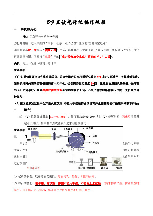
三工作原理和试样制备原子发射光谱分析所采用的原理是用电弧(或火花)的高温使样品中各元素从固态直接气化并被激发而发射出各元素的特征谱线,用光栅分光后,成为按波长排列的“光谱”,这些元素的特征光谱线通过出射狭缝,射入各自的光电倍增管,光信号变成电信号,经仪器的控制测量系统将电信号积分并进行模/数转换,然后由计算机处理,并打印出各元素的百分含量。
⑴试样的制备:取样要有代表性,没有气孔、裂纹、砂眼和夹渣。
⑵样品的磨制:要平整、有纹理、磨完不能用手摸,不能沾上水或油。
(要求样品平整,防止激发时漏气。
用手摸,沾水或油,都可能导致样品激发不好或不激发)⑶激发部位:圆形试样打在半径的1/2处,不规则的试样打在对角线的1/2处(不能在同一部位激发多点)。
四预热(使用废样预热)每天都做步骤:点键盘上的“F11” 2-3次光谱仪预热好坏的判断(1)看点子:中间有银白色金属熔融物,外圈有黑色或褐色的放电物(铸铁可能没有黑圈)。
安捷伦仪器操作步骤详解演示文稿

2、选择“文件—数据—打开”:
找到需要打开的文件,将其打开:
3、删除杂峰
除杂峰
将色谱图里的除主峰之外的其他杂峰选中后清除。
4、选择界面下地“定义单峰”:
输入峰名称(自己命名):
5、点击“峰/组表”,将级别1、2、3分别设为 自己配制的标准溶液的浓度值。拟合类型选择 线性。
6、点击“分析—分析/单级校正”:
待黄色条变成紫色条,说明方法已平 衡,可以进样。
13、进样
(1)、 用尖头的进样器准确吸取要测的溶液1ul。 注意:进样器内的气泡需排出。方法为:用
食指和中指夹住针芯顶部,针头插入溶剂中, 然后迅速吸取溶剂,再迅速将溶剂推出。反 复数次之后,即可将气泡赶出。
(2)、将样品由进样口进入到进样口中,进 样完成后,拔出针,立即按主机上的“start” 按钮:
过一段时间,显示“方法下载完毕”, 点击确定即可
10、等待GC就绪
ቤተ መጻሕፍቲ ባይዱ
本实验配制的标准溶液为: 0.13ppm、0.39ppm、0.65ppm。
进样量为:1ul
11、待GC处于就绪状态:
点击单次运行采集的图标:
选择数据路径的位置,以及命名数据文件的名称即可,然后点 击“开始”
12、等待平衡方法,此时右下角显示 为黄色条。
14、样品正在分析中,右下角变成蓝 色条:
15、等待样品在设置的时间段内的谱 图均出来时,即可进下一个样品。
上图为第一个标准溶液(0.13ppm)的谱图。
16、测其他溶液:
重复上述第10步—第15步的步 骤即可。
0.39ppm的谱图:
0.65ppm的谱图:
未知样品的谱图:
二、数据分析(打开前关闭在线的程序) 1、在7820处右击鼠标,选择“离线打
安捷伦AgilentEB频谱分析仪使用说明简介

Agilent E4402BESA-E Seri^ Spectrum Analyzer 彳吏用万法间介宁波之猫2009-6-171简介 ..................................2. 面板 .................................2.1操作区...............................2.2屏幕显不.............................3. 各功能区的使用 ............................3.1 Control (控制)功能区.......................3・1.1 Freque ncy Channel : .................................3.1.2 Spa n X Scale ...........................................3.1.3 Amplitude Y Scale ...........................................3.1.4 In put/Output .............................................3.1.5 View/Trace ................................................3.1.6 Display ..................................................3.1.7 Mode ...................................................3.1.8 Det/Demod ................................................3.1.9 Auto Cuple ................................................3.2 Measure (测量)功能区......................3.2.1 Measure .................................................3.2.2 Meas Setup ...............................................3.2.3 Meas Con trol .............................................3.3 System (系统)功能区........................3.3.1 System ...................................................3.3.2 Preset .................................... 错误!未指定书签3.3.3 File ......................................................3.3.4 Print Setup&Print .............................................3.4 Marker (标记)功能区 ............ 错误!未定义书签3.4.1 Marker ...................................................3.4.2 Peak Search ...............................................3.4.3 Freq Count ................................................3.4.4 Marker — .................................................测试步骤举例1简介Agile nt ESA-E系列是能适应未来需要的Agile nt中性能频谱分析仪解决方案。
安捷伦高效液相色谱仪操作说明

资料范本本资料为word版本,可以直接编辑和打印,感谢您的下载安捷伦高效液相色谱仪操作说明地点:__________________时间:__________________说明:本资料适用于约定双方经过谈判,协商而共同承认,共同遵守的责任与义务,仅供参考,文档可直接下载或修改,不需要的部分可直接删除,使用时请详细阅读内容安捷伦高效液相色谱仪操作说明一、校枪及样品处理1. 校枪仪器:两个小烧杯、分析天平、移液枪1000μL、100μL步骤:打开分析天平预热,一只烧杯放到称量盘上调零,一只装入纯水。
将移液枪1000μL、100μL调至950μL、50μL,分别吸取纯水称质量,如偏大或偏小,调节移液枪直至准确到0.001g。
(如枪使用过久或气密性不好,可以准备一个小烧杯装入纯水,每次先轻轻沾湿枪口,甩掉水或在用卫生纸吸取口上的水,再插上枪头使用。
)注意慢吸慢放,不要挂珠。
2. 样品处理:用1.5mL离心管取0.5mL发酵液,取出样品后,首现在离心机上离心(13000rap/min 3min)。
然后将样品稀释20倍,取950μL纯水、50μL发酵液于离心管中。
混匀后在离心机上离心(13000rap/min 3min)。
准备自动进样瓶(瓶中放上内衬管),取200μL待测液盖紧盖子。
按顺序放到自动进样盘中。
二、开机1、仪器各组件将在线脱气器、泵:四元、进样器:自动进样器(六通阀)、柱温箱、检测器:示差折光检测器开关打开。
打开计算机,进入Windows XP 画面,并运行CAC Server程序,打开色谱仪各组件电源,待显示已联上各组件的信息及各模块自检完成后,双击Instrument 1 Online ,图标打开工作站。
化学工作站自动与1200LC通讯。
流动相:将流动相(一般不主张使用偏酸、偏碱的流动相)放入溶剂瓶中,打开冲洗阀,设流速为2ml/min,单击确定,再依次单击泵→控制,选中启动,单击确定,则系统开始冲洗,至管路无气泡为止,切换管路反复操作至所需管路均无气泡。
- 1、下载文档前请自行甄别文档内容的完整性,平台不提供额外的编辑、内容补充、找答案等附加服务。
- 2、"仅部分预览"的文档,不可在线预览部分如存在完整性等问题,可反馈申请退款(可完整预览的文档不适用该条件!)。
- 3、如文档侵犯您的权益,请联系客服反馈,我们会尽快为您处理(人工客服工作时间:9:00-18:30)。
Agilent (86140B) 光谱分析仪操作指导书—测试
文件编号 版本号 生效日期
5.使用注意:
提示:常见问题解决指南:
1)仪器必须安放在温度变化小,无振动的场所,温度变化和振动会导致光谱分析仪内 1. 无法设置或无光状态:请确认是否连接宽带光
部的单色仪光路失准从而造成幅度误差;
源或打开宽带光源输出;
第6页共9页
Agilent (86140B) 光谱分析仪操作指导书—测试
E.扫描参数设置 (1)深度扫描(默认设置-85dB,常应用于双级隔离器)
(2))普通扫描(默认设置 1KHz,常应用于单级隔离器)
第7页共9页
文件编号 版本号 生效日期
E.说明:设置扫描参数(普通模式设为 1KHz,深度 扫描为-85dB)[图 10—图 11] [图 10]Amplitude(21)--Sensitivity(22) ---85—dB /{[图 11]Bangwith Sweep(23)—Vide BW(24)—1—KHz.}(大括号中为普通设置)
参考:关于标识操作(MARKER)(内容相关:[5 页图 9] 基本标识及设定:MARKER 、SET MARKER(ACTIVE MARKER)、 MARKER SETUP 带宽标识:BANDWIDTH MARKER(-3dB,-6dB,-10dB) 峰/谷搜索:SEARCH MODE(---PEAK MODE -ACTIVE MARKER --PEAK SEARCH(最大值搜索) SEARCH MODE — PIT MODE -ACTIVE MARKER --PIT SEARCH(最小值搜索) 相关操作:NEXT PEAK DOWN、NEXT PEAK LEFT 、NEXT PEAK RIGHTT 改变中心波长标识:MARKER TO CENTER 三角标识:DELTA MARKER 波长标识:Wavelength Marker
Agilent (86140B) 光谱分析仪操作指导书—测试
F.补充(1)
文件编号 版本号 生效日期
F.说明(1):作参考⑵-锁定 B 通道[图 12] [图 12]Traces(25)—Active(26)—Tr B—Update B{on/off}(27)打在 off 上,即锁定 B 通道。
提示:应用时一定要锁定 B 曲线!即保持 Update B 在 off 的状态上.锁定 B 曲线时,请先激活 B.
参考:波长扫描设定: Center Wavelength:中心波长 Start Wavelength:起始波长(700-1800nm) Stop Wavelength: 停止波长(700-1800nm) Span: 扫描带宽设定 Peak to Center:设定光谱信号的幅度峰值所对应的波长 为中心波长 中心波长=(起始波长+结束波长)/2 扫描带宽=起始波长-结束波长 选择真空/空气波长:AIR / vacuum
4.设置步骤(以 1550 隔离器为例) 1)开机及自校
第1页共9页
ห้องสมุดไป่ตู้
1)说明:电源—自校[图 1] LINE(1 电源开关)—Auto Align(2 自校) 提示:移动设备后或长期未使用(5 日)时请自校。
Agilent (86140B) 光谱分析仪操作指导书—测试
文件编号 版本号 生效日期
2)设置步骤总述: (1)电源—自校(移动设备后或长期未使用时请自校) [LINE]电源—Auto Align 校准 (2)扫描带宽设定 [Wavelength] 波 长 —[Start WL] 起 始 波 长 —1530—nm—[Stop WL] 终 止 波 长 —1570—nm (3)作参考⑴ [Traces] 轨 迹 线 —[Active Trac] 轨 迹 线 选 择 —[Tr A] 轨 迹 线 A—[ Active Trac]—[Tr B]B 线—[Active Trac]—[Tr C]C 线—[Trace Math OFF]数学模式选择 --[Default Math Trace C]默认运算,指定 C—[Log Math C=A-B]指定运算方式(默 认) (4)设置浮标 [Markers]浮标—[Active Marker]浮标选择—[Mkr1]浮标 1—1530(点)—nm —[Active Marker]—[Mkr2]—1550—nm—[Active Marker]—[Mkr3]—1570—nm (5)设置扫描参数(普通模式设为 1KHz,深度扫描为-85dB) [Amplitude]幅度—[Sensitivity]深度(灵敏度)—85—dB /[Bangwith Sweep]频宽—[Vide BW]频宽设定--1—KHz 单位 (6)作参考⑵-锁定 B 通道 [Traces]轨迹—[Active]轨迹活动—[Tr B]B 线—[Update B]{on/off}B 线锁定 (7)选择扫描方式(重复扫描/单次扫描) [Bandwidth Sweep]扫描—[Repeat Sweep]{on/off}重复扫描选择 —[Single sweep]单次扫描
6)在 OPTICAL INPUT 输入端只能使用单一模式激光,不能使用多模式激光,否则会 4. 浮标不显示器件参数或只有光源读数:请确认
造成回损与插入损耗的增大 ;
是否锁定 B 曲线, 即保证 B 曲线在 off 的位置
7)光谱分析仪器无法满足要求时会显示警告;超出范围的参数项目,及其违反或无 上;
提示:依次激活 A、B、C 曲线.
参考:曲线操作(Trace) 曲线共有 A、B、C、D、E、F 激活曲线:Acitve Trace (使用之前必须激活当前曲线) 是否更新(锁定)曲线:UPDATE On/Off 关闭或显示曲线:VIEW OFF/ON 设定 HOLD 功能: HOLD
第4页共9页
Agilent (86140B) 光谱分析仪操作指导书—测试
第3页共9页
Agilent (86140B) 光谱分析仪操作指导书—测试
C.作参考
文件编号 版本号 生效日期
C.说明:作参考⑴[图 4—图 8] [图 4]Traces(8)—Active Trac(9)—[图 5]Tr A(10)-- Active Trac(9)-- Tr B(11)-- Active Trac-- Tr C(12)—[4 页图 6]Trace Math OFF (13)--[4 页图 7]Default Math Trace C(14) —[5 页图 8]Log Math C=A-B(15)
第2页共9页
Agilent (86140B) 光谱分析仪操作指导书—测试
3)设置步骤详解 A.光源线与 OSA 线相接 B.设置扫描波段范围
审核
文件编号 版本号 生效日期
B.说明:扫描带宽设定[图 2]—[图 3] [图 2]Wavelength(3)—Start WL(4)—[图 3]1530 (5)—nm(6)—Stop WL(7)—1570—nm.
法辩认的终端,也会发出警告;
5. 参考时系统值差异较大:请确认连接头是否拧
8)出现“UNCAL”(无法测量)时,此信息指出部分设定将导致测量无效;
Agilent (86140B) 光谱分析仪操作指导书—测试
文件编号 版本号 生效日期
1.目的 指导 Agilent(86140B)OSA 的操作规范,保证使用此型号设备测试工作的正常开 展。 2.范围 使用 Agilent(86140B)OSA 的测试工序。 3.Agilent(86140B)OSA 示意图
参考:1.扫描参数设定: Sensitivity :灵敏度设定 自动灵敏度测定(Automatic mode) 手动灵敏度测定(Manual mode) Bandwidth: 扫描的视频带宽(3kHZ-100M) 改变灵敏度,参考电平可影响视频带宽(VBW) RBW:分辩率带宽设定 (0.06,0.07,0.1, 0.2, 0.5, 1, 2, 5, 10nm) 2.参数设定注意: 2.1 设定分辩率带宽(RBW)分辩率带宽设定与所测的光 源类型相关,使用宽带光源(ASE,EELED )必须设定较 大的分辩率带宽(RBW),使用窄带光源(DFB,必须设定 较小的分辩率带宽(RBW) 2.2 设定不准确的分辩率带宽(RBW)会给测量带来不准 确 2.3 灵敏度设定、视频带宽与扫描时间相互影响 2.4 设定好灵敏度可以测度信号的最小功率,但较高的灵 敏感度会影响测量时间 2.5 设定功率的峰值为参考电平可以使信号的幅度最合 适,它决定光谱分析仪器内部
Wavelength marker 1(波长 1 标识) Wavelength marker 2(波长 2 标识) 使用标识变更参考电平: Marker to reference level 改变默认标识设定:Marker Setup 关闭所有线性标识:All line markers off 在标识间扫描: Sweep Limit 在标识间搜索: Search Limit 在标识间的积分:Integrate Limit 曲线的总功率: Trace integration
“说明”与“提示”部分为正文内容,“说明”为 所附图片之解释;“提示”部分为设备应用与常见 错误分析。 “参考”部分仅供了解,使之对设备有更详尽的 掌握。
参考:操作要点: 为准确测量仪器必须经开机预热 30 分钟以上,然后 Auto Align 自动对准。 自动扫描: Auto Sweep:用于对未知光功率幅度和未知光中心波长的 光源测量(光谱分析仪使用默认的扫描参数在光谱分析 仪的扫描波长全程范围内扫描,并由激光的强度峰值获 得中心波长)
第5页共9页
Agilent (86140B) 光谱分析仪操作指导书—测试
文件编号 版本号 生效日期
D.设置浮标
D.说明:设置浮标[图 9] [图 9]Markers(16)—Active Marker—Mkr1(17) —1530—nm—Active Marker—Mkr2 ( 18 ) —1550—nm—Active Marker—Mkr3 ( 19 ) —1570—nm.如有需要可设置浮标 Mkr4(20) 提示:请在激活 C 时设置浮标!