布鲁克Quantax 400能谱仪说明
Bruker AV400 NMR 谱仪操作步骤

Bruker A V400 NMR谱仪操作步骤叶剑良廖新丽 2005-10-13一.实验步骤1. 用户名:av400,密码:av4002. 进入系统后打开Topspin操作系统: 点击桌面上topspin1.3快捷键3. 将spinner(蓝色转子)放在样品规上,插入核磁管直到到样品规底部(建议样品管中溶液高度在4cm左右(约0.55ml,);若溶液高度过低则使液柱沿样品规外黑色标记对称分布(即液柱中心与黑色标记重合)。
注意:溶液太少不利于自动匀场,易影响最后谱图质量;另外每次所配样品溶液高度一致,有利于实验快速、高质量完成。
4. 观察界面下方的采样状态小窗口,确认没有实验正在进行5. 输入指令:ro off,停止探头中原有样品的旋转6. 输入指令:ej,弹出探头中原来样品注意:每一指令是否完成,看命令输入行下面的进程指示,只有当前的指令所执行的进程结束后方可输入下一指令7. 将已在spinner中放好的样品放入探头中8. 输入指令:ij,压缩空气自动将样品送入探头9. 在主工具条中选择Spectrometer-Data Acquisition Guide,打开采样流程图,初期可按流程图一步一步进行实验,熟悉以后也可输入指令进行操作:10. 流程1:New Experiment(等同于指令new,在命令输入行(topspin界面下方)输入)在跳出的窗口中填入:NAME:实验名(如样品名,编号等)EXPNO:实验号(只能是正整数,且在同一实验名下不存在,否则将冲掉原来数据)PROCNO:处理号(只能是正整数,且在同一实验名下不存在,否则将冲掉原来数据;同一数据可以以不同方式处理)DIR:存盘目录(D盘,不用改动)USER:用户名(管理人员已建立,一般为课题组长姓名)SOLVENT:在下拉窗口中选择所用溶剂(注意选择正确的溶剂名称,否则将导致后面实验出错)EXPERIMENT:在下拉窗口中选择实验类型,氢谱选PROTON256;碳谱选C13CPD;磷谱:不去偶选P31,去偶选P31CPD。
布鲁克 兆核磁操作使用指南
布鲁克400兆核磁氢谱操作使用指南1.氢谱——进入到topspin操作界面,用高度量桶准确量测核磁管高度后,键入ej命令,气体自动吹出,等到感觉气体气流最大时,放入样品,然后在topspin界面上,键入ij命令,样品自动下滑到探头位置。
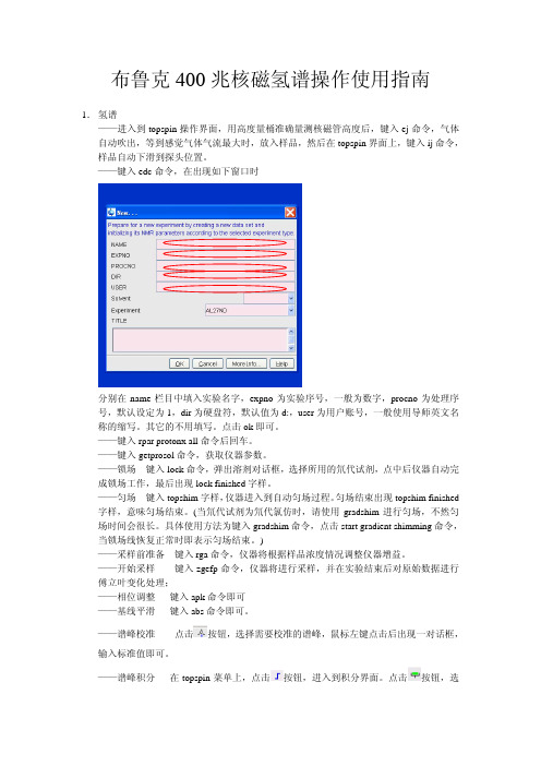
——键入edc命令,在出现如下窗口时分别在name栏目中填入实验名字,expno为实验序号,一般为数字,procno为处理序号,默认设定为1,dir为硬盘符,默认值为d:,user为用户账号,一般使用导师英文名称的缩写。
其它的不用填写。
点击ok即可。
——键入rpar protonx all命令后回车。
——键入getprosol命令,获取仪器参数。
——锁场键入lock命令,弹出溶剂对话框,选择所用的氘代试剂,点中后仪器自动完成锁场工作,最后出现lock finished字样。
——匀场键入topshim字样,仪器进入到自动匀场过程。
匀场结束出现topshim finished 字样,意味匀场结束。
(当氘代试剂为氘代氯仿时,请使用gradshim进行匀场,不然匀场时间会很长。
具体使用方法为键入gradshim命令,点击start gradient shimming命令,当锁场线恢复正常时即表示匀场结束。
)——采样前准备键入rga命令,仪器将根据样品浓度情况调整仪器增益。
——开始采样键入zgefp命令,仪器将进行采样,并在实验结束后对原始数据进行傅立叶变化处理;——相位调整键入apk命令即可——基线平滑键入abs命令即可。
——谱峰校准点击按钮,选择需要校准的谱峰,鼠标左键点击后出现一对话框,输入标准值即可。
——谱峰积分在topspin菜单上,点击按钮,进入到积分界面。
点击按钮,选择原先被积分的谱峰,点击按钮,删除原先谱峰的积分。
确认后即可删除。
然后,点击按钮,利用鼠标左键选择需要积分的谱峰。
具体做法是按着鼠标左键不松手,选择需要积分的谱峰后松手,积分即可完成。
重复上述过程,直到所用谱峰都被积分。
bruker avance ⅲ 400写法

【主题】bruker avance ⅲ 400使用方法【内容】1. bruker avance ⅲ 400是一款高级的核磁共振仪器,广泛应用于化学、生物、医药等领域。
使用该仪器需要遵循一定的操作规程和方法。
2. 在使用bruker avance ⅲ 400之前,需要对仪器进行检查和保养。
确保仪器的各项功能正常,仪器表面清洁无污垢,以免影响实验结果。
3. 打开仪器时,需要按照操作手册上的指示进行。
首先打开电源开关,然后启动系统软件,等待仪器初始化完成。
4. 使用bruker avance ⅲ 400进行核磁共振实验时,需要准备好样品。
样品的制备需要严格按照实验要求进行,确保样品的纯度和浓度符合要求。
5. 将样品放置到仪器的样品舱内,然后进行参数设置。
根据需要选择合适的探头、核素和实验模式,设置合适的扫描参数等。
6. 在实验过程中,需要密切关注仪器的运行状态。
确保实验过程中各项参数稳定,避免出现异常情况。
7. 实验完成后,需要及时关闭仪器并进行清洁和保养。
清洁仪器的表面和内部,保持仪器的整洁和良好状态。
8. 使用bruker avance ⅲ 400进行实验需要严格遵守相关的安全规定。
确保操作人员和实验环境的安全,避免意外事件的发生。
9. 对于初学者来说,使用bruker avance ⅲ 400可能需要一定的学习和实践。
建议在有经验的人员指导下进行操作,避免出现不必要的错误。
10. 正确的使用方法和操作规程对于保证bruker avance ⅲ 400仪器的稳定运行和实验结果的准确性非常重要。
希望使用者能够严格遵守相关规定,提高实验效果和安全性。
11. 在使用bruker avance ⅲ400进行核磁共振实验时,需要根据实验的具体要求进行参数设置。
对于不同类型的样品和实验目的,需要调整频率、脉宽、扫描数等参数,以确保实验能够得到准确可靠的结果。
12. 在设置参数的过程中,操作人员需要充分了解仪器的各项功能和性能特点,以便合理调整参数。
布鲁克XRF荧光光谱仪说明书 7-MeasMethod-测量方法

MeasMethod测量方法目录1 开始1.1 MEASMETHOD 的目标1.2 屏幕导向1.3 管理MEASMETHOD 文件1.3.1 启动MEASMETHOD 和创建新的测量方法1.3.2 打开和保存测量方法2 设置测量方法2.1 设置测量参数2.2 选择测量的元素2.2.1 在无标样方法2.2.2 在定量方法2.3 选择分析谱线2.4 查看和管理需要测量的谱线2.5 设置测量模式和时间2.5.1 理论知识介绍2.5.2 设置测量模式时需考虑的事项2.5.3 设置测量时间2.5.4 设置峰位测量2.5.5 设置背景测量2.5.6 设置死时间校正模式2.5.7 Scan-扫描选项的说明2.5.8 Fixed-固定选项的说明2.5.9 Optimized –优化选项的说明2.6 重校正选项索引MeasMethod1 开始1.1 MEASMETHOD 的目标MEASMETHOD保存和编辑MM文件,即定义用光谱仪测量样品时的测量参数。
这些参数包括:・光谱仪模式(vacuum-真空;vacuum with seal,真空并有真空封档,helium-氦气)・样品是否旋转・准直器面罩型号・测量模式・测量的元素及谱线・测量时间和步长・重校正样品谱线是保存在谱线库(S4-LineLibrary.fll1),并在MEASPARAMETERS 程序里编辑。
谱线由下列参数定义:X-射线管的管压、滤片、所用的准直器、分光晶体,2θ测量位置,所用的探测器、及对应的脉冲高度分析器(PHA)的窗口。
根据Siegbahn命名法则,谱线名称反映了电子的跃迁和产生(如 Fe KA1 是铁的Ka1 谱线)。
因此,同一条谱线可用于多个测量方法;可以在不同的条件(如:气氛模式、测量时间、面罩…)的测量,并可用于不同定量程序的校准。
测量条件在MEASMETHOD里定义,并补充该谱线的测量参数。
1.2 屏幕导向MEASMETHOD 屏幕包括:・标题内容有:项目说明Elements 当前方法测量的元素数Lines: Total 当前所选元素在谱线库可选的谱线总数(注意,如果没有元素被选时,也包括Compton 谱线)Total Time 如果测量是设置为Fixed,测量总时间Active 测量的谱线数Created 创建日期Last Change 最后修改・可进入6个设置选项栏。
BRUKER AVANCE III HD 400 核磁共振波谱仪操作方法

BRUKER AVANCE III HD 400 核磁共振波谱仪操作方法(氢谱、碳谱)1 手动方法开启空压机拿掉探头上的盖子输入ej,放入新样品后,输入ij送入探头中输入new,新建一个实验,填写文件名name,实验号 expno(一般氢谱为1,碳谱2),处理号procno为 1;Experiment选择标准实验,氢谱PROTON,碳谱C13CPD;点选Execute “getprosol”;DIR选择数据保存的目录,一般是D盘,点击OK输入lock,在弹出的菜单中选择溶剂名称,锁场输入atma,调谐探头(变换杂核核素时,第一次用半自动调谐atmm)输入topshim,匀场输入rga,自动调整增益输入ased,进入关键参数界面,检查p1、plw1(脉宽与功率)是否正确,ns、sw是否合适输入zg,采样,碳谱输入go可以累加采样结果数据处理:输入efp,进行傅里叶变换,输入apk,相位校正,输入abs,基线校正,输入sref,自动校正内标位移;点击菜单Process下Pick Peaks图标进行手动标峰,Integrate手动积分输入plot,打印模板设置,输入print,打印图谱做完全部样品,当弹出最后一个样品后,盖上探头上的盖子,关掉空压机注意事项:确保所用核磁管无破损、划痕弹出样品前,一定要检查盖子是否拿掉,以免核磁管碰到盖子破碎放入样品前,要确认有气流,以免核磁管直接掉下去撞到底部破碎采样前要检查脉冲宽度、功率是否正确,以防脉宽太长、功率太大烧坏探头BRUKER AVANCE III HD 400 核磁共振波谱仪操作方法(氢谱、碳谱)2 自动进样器开启空压机拿掉探头上的盖子输入icon,打开Icon NMR程序,点击Automation,选择heci用户名,点击OK,进入Automation窗口,在Experiments Table 中可设置实验,在Preceding Experiments中可看到正在运行和已经完成的实验打开自动进样器:1 )插上自动进样器电源,2)打开气路开关,3)拉起红色紧急开关将样品依次放入转盘,记下其Holder,在Experiments Table区域中,选中相应样品的Holder,双击即可设置实验参数,Disk选择数据保存目录, Name 选择文件名, No选择expno, Solvent选择溶剂,Experiment 选择标准实验, Par可以修改参数点击add可添加新的实验(同一holder的不同谱类),点击copy增加新的实验(不同holder),设置好后,选中实验点击submit提交,如需修改已提交实验,选中后先点击cancel,然后点击edit,全部提交后点击start,在弹出窗口中First Sample 选择开始的holder,点击start运行,Automation将依次完成所提交的实验。
布鲁克400mhz核磁共振谱仪 检出限

布鲁克400mhz核磁共振谱仪检出限布鲁克400MHz核磁共振谱仪是一种常用的仪器,用于分析和确定物质的结构和化学性质。
它的检出限是指仪器能够可靠地检测到的最低浓度,即样品中最低浓度的分子或离子的浓度。
本文将介绍布鲁克400MHz核磁共振谱仪的检出限及其影响因素,并讨论其应用和改进。
检出限是核磁共振谱仪的重要性能指标之一,它对于分析和检测微量物质具有重要意义。
检出限的确定方法可以是信噪比法、标准偏差法、信号幅度法等,具体方法选择根据实际需要和仪器的特点而定。
布鲁克400MHz核磁共振谱仪的检出限受多种因素影响。
首先是仪器的灵敏度,即谱线的信噪比。
信噪比越高,检出限就越低。
布鲁克400MHz核磁共振谱仪的高磁场强度和优质的探头设计能够显著提高信号强度和信噪比,从而提高检出限。
其次是样品的浓度和纯度。
低浓度的样品会导致信号弱,从而增加了检出限。
此外,样品的纯度也会对检出限产生影响。
纯度越高,杂质信号越少,信噪比越高,检出限越低。
因此,为了得到更低的检出限,需要优化样品的制备和纯化方法,并尽量保证样品的浓度和纯度。
此外,仪器的工作环境和使用条件也会对检出限产生影响。
例如,周围环境中的电磁干扰、仪器的温度和湿度等因素都可能影响到信号的强度和稳定性,从而间接影响检出限。
因此,在使用布鲁克400MHz核磁共振谱仪时,应注意消除干扰和保持仪器的稳定工作状态,以获得更好的检出限。
布鲁克400MHz核磁共振谱仪的检出限在许多实际应用中具有重要的意义。
例如,在生物医学领域中,对于分析体内微量代谢产物或药物代谢产物,检出限的高低直接影响到结果的准确性。
此外,在环境污染监测、食品安全检测等领域中,也需要对样品中微量的有机物或无机物进行检测,因此低检出限的核磁共振谱仪具有重要的应用价值。
为了进一步提高布鲁克400MHz核磁共振谱仪的检出限,可以采取多种改进措施。
例如,可以优化仪器的硬件设计,提高信号检测和放大电路的性能。
布鲁克核磁共振仪初学者入门手册

版本号 003本手册所包含信息的更新、变更不再进行通知BRUKER 不承担依照本手册进行操作所造成的一切后果。
BRUKER 不负责在安装或实验操作中由于本手册所包含的错误而导致的偶然损害。
严禁在未取得出版者书面许可的情况下,对手册全部或部分内容进行引用或者翻译。
作者:Eamonn Butler出版:Stanley J.Niles2003年12月12日翻译:高玉波 Yubo.Gao校对:2006年5月21日目录目录 (3)1 简介.............................................................................................................................................71.1可能的损害.......................................................................................................................71.1.1软件版本及命令语法...........................................................................................82 安全注意事项 (9)2.1简述 (9)2.2 关于磁性的安全注意事项 (9)2.2.1 内部区域安全注意事项 (10)2.2.2 外部区域安全注意事项 (11)2.3 关于深冷液体的安全注意事项 (11)2.4 关于电气的安全注意事项 (11)2.5 关于化学的安全注意事项 (11)2.6 关于CE认证 (11)3 理论及术语说明 (13)3.1 简介 (13)3.2 氯仿的NMR分析 (15)3.3 标样,赫兹,ppm (17)3.4 质子NMR——化学位移 (18)3.5苯的质子频谱 (19)3.6 乙酸苄酯(Benzylacetate)的质子频谱 (20)3.7 带自旋/自旋耦合的乙基苯质子频谱 (21)3.8 去耦 (23)3.9 FID和频谱 (24)4 系统介绍 (27)4.1 简介 (27)4.2 操作控制台及其连接 (27)4.3 机柜 (28)4.4 主机与AQS间的连接 (29)4.5 磁体、匀场系统、HPPR和探头 (29)4.6 磁体和磁体杜瓦 (31)4.6.1 室温腔管 (32)4.6.2 液氦腔 (32)4.6.3 液氮腔 (33)4.7 锁场系统简介 (33)4.8 探头 (34)4.8.1 双模13C/1H探头 (36)4.8.2 更换探头 (38)5 NMR样品 (39)5.1 简介 (39)5.2 溶剂选择 (39)5.3 样品管 (40)目录5.4 样品处理 (41)6 实验基本步骤 (43)6.1 简介 (43)6.2 BSMS键盘 (43)6.2.1保存一组匀场值(wsh命令) (44)6.2.2 读取一组匀场值(rsh命令) (44)6.2.3 BSMS功能 (45)6.2.4 样品控制功能 (45)6.2.5 手动锁场功能 (45)6.2.6 手动匀场功能 (46)6.2.7 液氦高度功能 (46)6.3 将样品管插入转子 (47)6.4 将带样品管的转子放入磁体 (47)6.5 旋转样品 (48)6.6 调谐和匹配探头 (49)6.6.1 使用wobble曲线进行调谐和匹配 (49)6.6.2 使用HPPR LED进行调谐和匹配 (51)6.6.3 对多个核进行调谐和匹配 (52)6.7 锁定样品 (53)6.7.1 锁场步骤 (54)6.8 匀场 (55)6.8.1 初始匀场 (56)6.8.2 常规匀场 (56)7准备采样——数据集, edasp、eda命令 (59)7.1 简介 (59)7.2 数据集 (59)7.3 创建数据集 (61)7.4 谱仪参数edasp (62)7.4.1 edasp窗口布局 (63)7.4.2 edasp窗口的一些特性 (65)7.5 基本采样参数:“eda”表 (65)7.5.1 发射、基础和偏移频率的数学解释 (72)8 脉冲程序 / ased命令 (75)8.1 脉冲程序“zg”和“zg30” (75)8.2 “zg30”程序详解 (75)8.3 命令“ased” (77)9 氢谱 (79)9.1 前言 (79)9.2 创建新数据集 (79)9.3 读取标准参数集 (80)9.3.1 “getprosol”表 (80)9.4 设置接收机增益 (80)9.5 进行采样 (81)9.6 傅立叶变换和谱图相位校正 (83)目录9.7 基本处理:傅立叶变换 (85)9.8 相位校正 (85)9.9 谱图的校准 (87)9.9.1 水平放大图谱 (88)9.9.2 图谱校准 (88)9.10 使用SW-SFO1功能调整谱宽 (89)9.10.1 调整cholesterylacetate谱图的SW (89)9.11 增加扫描次数 (90)10 不去耦的13C谱 (93)10.1 简介 (93)10.2 步骤 (93)11 去耦氢的13C谱 (97)11.1 简介 (97)11.2 详细步骤 (97)11.3 确定去耦频率 (98)11.4 调整去耦参数 (99)11.5 脉冲程序zgpg30 (99)12 基本故障排除 (103)12.1 简介 (103)12.2 打开和关闭谱仪 (103)12.3 谱仪开机 (103)12.4 谱仪关机 (104)12.4.1 在Windows系统运行Topspin (104)正文开始1 简介这本手册的目的是帮助一个几乎没有经验的用户学习进行一系列基础的一维高分辨率NMR实验。
布鲁克 核磁共振光谱仪器介绍

布鲁克核磁共振光谱仪器介绍一、引言核磁共振光谱仪(Nuclear Magnetic Resonance Spectrometer, NMR)是一种通过研究物质中原子核的磁共振现象来获取物质结构和性质信息的仪器。
布鲁克公司是一家世界知名的科学技术公司,其核磁共振光谱仪在科研和工业界都有着广泛的应用。
本文将介绍布鲁克核磁共振光谱仪的基本原理、技术特点、应用领域及未来发展趋势。
二、基本原理核磁共振光谱仪利用原子核在外加磁场作用下的共振现象来获取原子核周围的电子环境信息。
当原子核在外加磁场中受到射频脉冲的作用后,会吸收或发出特定频率的辐射,从而产生共振信号。
根据原子核的不同化学环境,共振信号的频率和强度也会有所不同,通过分析这些共振信号可以得到样品的化学结构和性质信息。
三、技术特点1. 高灵敏度:布鲁克核磁共振光谱仪具有高灵敏度的特点,可以探测低浓度的样品,并且在高分辨率下获取共振信号,能够更精确地确定样品的结构和性质。
2. 多维谱学:布鲁克核磁共振光谱仪支持多维谱学实验,可以通过多种角度观察样品的共振信号,从而获取更全面的信息,提高样品分析的准确性。
3. 自动化控制:布鲁克核磁共振光谱仪具有自动化控制系统,可以进行多组样品的连续分析,提高实验效率,并且可以自动记录和处理数据,减少人为误差。
4. 多样化样品支持:布鲁克核磁共振光谱仪支持多种样品类型的分析,包括溶液样品、固体样品和生物样品等,广泛适用于化学、材料、生物等领域的研究。
四、应用领域布鲁克核磁共振光谱仪在科学研究和工业生产中有着广泛的应用。
主要包括以下几个方面:1. 化学研究:布鲁克核磁共振光谱仪可以用于分析有机化合物、无机化合物、配位化合物等,对化合物的结构和性质进行详细研究,为新材料的设计和合成提供重要依据。
2. 药物研发:在药物研发过程中,布鲁克核磁共振光谱仪可以用于分析药物的结构、纯度和稳定性,保证药物的质量和安全性。
3. 生物医学研究:布鲁克核磁共振光谱仪可以用于分析生物大分子如蛋白质、核酸等的结构和功能,对于生物医学领域的研究具有重要意义。
Bruker能谱仪
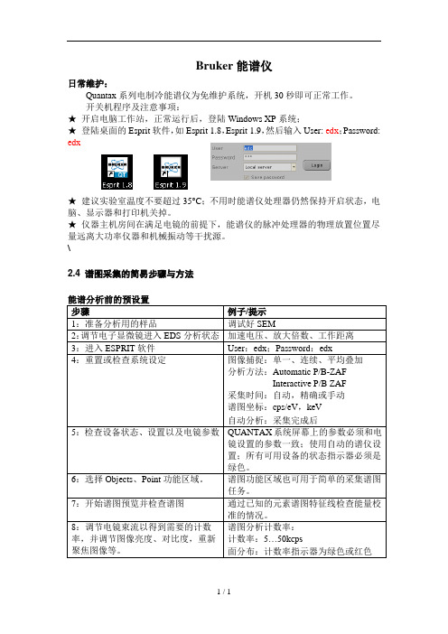
Bruker能谱仪日常维护:Quantax系列电制冷能谱仪为免维护系统,开机30秒即可正常工作。
开关机程序及注意事项:★开启电脑工作站,正常运行后,登陆Windows XP系统;★登陆桌面的Esprit软件,如Esprit 1.8,Esprit 1.9,然后输入User: edx;Password: edx★建议实验室温度不要超过35°C;不用时能谱仪处理器仍然保持开启状态,电脑、显示器和打印机关掉。
★仪器主机房间在满足电镜的前提下,能谱仪的脉冲处理器的物理放置位置尽量远离大功率仪器和机械振动等干扰源。
\2.4 谱图采集的简易步骤与方法步骤例子/提示1:准备分析用的样品调试好SEM2:调节电子显微镜进入EDS分析状态加速电压、放大倍数、工作距离3:进入ESPRIT软件User:edx;Password:edx4:重置或检查系统设定图像捕捉:单一、连续、平均叠加分析方法:Automatic P/B-ZAFInteractive P/B ZAF采集时间:自动,精确或手动谱图坐标:cps/eV,keV自动分析:采集完成后5:检查设备状态、设置以及电镜参数QUANTAX系统屏幕上的参数必须和电镜设置的参数一致;使用自动的谱仪设置;所有可用设备的状态指示器必须是绿色。
6:选择Objects、Point功能区域。
谱图功能区域也可用于简单的采集谱图任务。
7:开始谱图预览并检查谱图通过已知的元素谱图特征线检查能量校准的情况。
8:调节电镜束流以得到需要的计数率,并调节图像亮度、对比度,重新聚焦图像等。
谱图分析计数率:计数率:5…50kcps面分布:计数率指示器为绿色或红色。
能谱仪的操作方法与结果分析

能谱仪的操作方法与结果分析引言:能谱仪是一种重要的仪器设备,广泛应用于物理、化学、生物等领域的研究中。
它能对样品中的粒子进行能量分析和检测,从而揭示样品的特性和内部结构。
本文将介绍能谱仪的操作方法以及如何分析并解读得到的结果。
一、能谱仪的操作方法能谱仪的操作方法主要包括准备样品、设置仪器参数、进行测量和数据处理等步骤。
首先,准备样品。
根据具体的研究目的,选择适当的样品。
例如,在材料研究中,我们可能需要测量不同材料的X射线能谱;在环境监测中,我们可能需要测量空气中的放射性物质。
将样品准备好,确保其符合实验要求并具有一定的数量。
然后,设置仪器参数。
根据样品的性质和研究的目标,调整能谱仪的各项参数。
这些参数包括电压、测量时间、探测器的选择等等。
通过合理设置仪器参数,可以提高测量的准确性和灵敏度。
接下来,进行测量。
将样品放入能谱仪中,启动仪器,进行数据的采集。
在测量过程中,要保持仪器的稳定性,避免外界因素的干扰。
同时,根据具体情况,调整仪器的工作模式和测量时间,以获得更好的数据。
最后,进行数据处理。
将测量得到的数据导入计算机软件中,进行分析和处理。
常见的数据处理方法包括谱线拟合、能谱峰面积计算、能谱图绘制等等。
通过这些处理,可以得到样品的能量分布情况和相关的参数。
二、结果分析与解读得到测量结果后,需要对其进行分析与解读。
这一步骤对于揭示样品的特性和内部结构非常重要。
首先,进行能谱峰的识别。
能谱图中的能谱峰代表了不同能量的粒子或射线的存在。
根据能谱峰的位置和强度,可以初步判断出样品中存在的元素或放射性物质。
其次,进行能谱峰的拟合。
能谱峰的拟合可以获得峰的位置、强度、宽度等参数。
通过对这些参数的分析,可以进一步了解样品的物理性质以及元素的种类和含量等信息。
然后,进行能谱图的绘制与分析。
能谱图可以直观地展示样品的能谱特性。
在绘制能谱图时,可以选择显示不同特征的能谱峰,进一步分析样品的成分和组成。
同时,可以通过比较不同样品的能谱图,研究样品之间的差异和相似性。
布鲁克400兆核磁操作使用指南

布鲁克400兆核磁操作使用指南正文:一、概述布鲁克400兆核磁共振成像系统(以下简称400兆核磁系统)是一种常用于医学诊断和科学研究的先进设备。
本操作使用指南旨在为用户提供400兆核磁系统的详细操作说明,以便正确、安全地操作该设备。
二、设备准备2.1 系统开机2.1.1 确保设备连接到电源,并检查电源线是否接触良好。
2.1.2 按下设备上的电源开关,待系统启动完成后进入下一步操作。
2.2 校准设备2.2.1 打开400兆核磁软件,并菜单栏中的“校准”选项。
2.2.2 依照提示,选择适当的校准程序进行校准。
2.3 准备样本2.3.1 将待测样本置于样本架上,并按照设备要求的样本数量和位置进行安放。
2.3.2 调整样本位置,确保样本与探测器之间的距离符合要求。
三、操作流程3.1 样本预处理3.1.1 清洁样本表面,确保没有污垢或杂质。
3.1.2 若需要对样本进行处理(如溶解、稀释等),按照实验要求进行操作。
3.2 开始测量3.2.1 在软件界面中选择适当的实验模式和参数设置。
3.2.2 “开始测量”按钮,启动测量过程。
3.3 数据处理3.3.1 扫描完成后,可将数据导出为常见的图像或数据文件格式。
3.3.2 根据需要,使用相关软件对数据进行处理、分析或重建图像。
四、安全事项4.1 操作前需佩戴防护手套和眼镜,以防样品溢出或喷溅造成伤害。
4.2 禁止在带电状态下打开设备外壳,以避免触电危险。
4.3 使用前请检查设备连接线是否完好,避免因电气故障造成设备损坏或人员伤害。
附件:1、布鲁克400兆核磁系统用户手册2、布鲁克400兆核磁系统校准程序法律名词及注释:1、校准:指对设备进行调整,使其满足指定的标准和要求的过程。
2、样本:指待测的物质或样品。
3、数据处理:指对实验获得的原始数据进行处理、分析或重建图像的过程。
布鲁克400MHz超导核磁共振谱仪上机操作培训

甲方:分析测试中心
乙方:
注上: 方打 时碎 进样 行品 其管 它造 动成 作探)头二污是染样的品问管题有:暗一裂是(违多规次操使作用(过程1、中未清开洗气不。当2、、样放品置管不已当经)气。流为托此在,磁请体有 关11元课/支题)组。用我们在2006年九月就指定的品牌样品管(在实验材料供应中心(705号楼二楼)领取,
布鲁克400MHz超导核磁共 振谱仪上机操作培训
. ..
关于开放NMR仪器的协约
甲方:校测试中心
乙方:பைடு நூலகம்排上机人员的课题组
甲方对乙方上机人员进行培训,考核,乙方上机人员取得合格证后必须遵守如下约定:
必验须 室严 必格 须遵 在守 专测 门试 登中 记心 簿实 上验 登室记的时各间种,规以章核制磁度室,时严钟格为遵准守,开进放出仪时器间的精规确定到。 分上 钟机 。者进出NMR实
核磁管
进样品管之前,需检查核磁管 核磁管是否有裂纹,破损
量规测量样品溶液高度-不低于40mm(溶质至少0.5mL)
当班操作造成磁体失超的;
违规操作造成核头烧坏;
打碎样品管,并造成探头污染,须返厂家修复的
其他违规操作,造成仪器损坏,修复在5万元以上的;
以上各项所需维修费用由测试中心承担50%,造成事故的上机者所在课题组应承担50%。
当班操作必须注意安全,卫生,不得大声喧哗,除送样人外,劝阻其他人进入NMR实验室。
容 师 复( 签 印包字。括,签送院字样系不人相得,关仿送领冒测 导 ,样 签 如品 字 果代 。 发号 请 现, 注 ,结 意 一构 , 律, 空 一溶 白 个剂 登 月, 记 之测 表 内试 可 不要 以 准求 复 测等印试),样,签品课字。题单目组不前导得本 单 将 本位 收 中对取心校一将内个不科样定研品期样检20品查0元测 各测试 课试费 题费用 组,优 的同惠 测时, 试该如 样课发 品题现 。组有将夹一带个外月样内,不或准者测横试向样样品品。,
布鲁克傅里叶变换红外光谱仪显微镜说明书
简介 . . . . . . . . . . . . . . . . . . . . . . . . . . . . . . . . . . . . . . . . . . . . . . . . . . . . 25 冷却探测器 . . . . . . . . . . . . . . . . . . . . . . . . . . . . . . . . . . . . . . . . . . . . . . . 25 检查信号强度 . . . . . . . . . . . . . . . . . . . . . . . . . . . . . . . . . . . . . . . . . . . . . 27 观察模式下样品的摆放 . . . . . . . . . . . . . . . . . . . . . . . . . . . . . . . . . . . . . . 29 透过模式下的测量 . . . . . . . . . . . . . . . . . . . . . . . . . . . . . . . . . . . . . . . . . 31 反射模式下的测量 . . . . . . . . . . . . . . . . . . . . . . . . . . . . . . . . . . . . . . . . . 32 使用 FPA 探测器进行测量 . . . . . . . . . . . . . . . . . . . . . . . . . . . . . . . . . . . 33
对该仪器的任何部件所做的任何维修调整和校准都必须严格按照当地国家的相关安全标准进行
布鲁克400mhz核磁共振谱仪 检出限

布鲁克400mhz核磁共振谱仪检出限布鲁克400mhz核磁共振谱仪是一种广泛用于化学、生物、药物和材料等领域的仪器,其检出限是指在一定条件下,仪器能够准确检测样品中特定成分的最小浓度。
在实际应用中,检出限是评价仪器灵敏度和分辨能力的重要指标之一,对于确保实验结果的准确性和可靠性具有重要意义。
布鲁克400mhz核磁共振谱仪的检出限受到多种因素的影响,包括仪器本身的性能、样品的性质、实验条件等。
首先,仪器本身的性能是影响检出限的关键因素之一。
400mhz核磁共振谱仪是一种高性能的仪器,具有较高的分辨能力和灵敏度,能够对样品中微量成分进行准确检测。
其高磁场强度和精密的探测器系统可以有效提高检出限,使得仪器能够对低浓度的成分进行精确测定。
其次,样品的性质也会影响检出限的大小。
不同类型的样品具有不同的化学成分和浓度范围,因此对于不同的样品,其检出限也会有所差异。
一般来说,对于含有多种成分的复杂样品,由于成分之间的相互干扰,检出限可能会相对较高。
而对于纯净的单一成分样品,其检出限一般会较低。
因此,在实际应用中,需要根据具体样品的性质进行合理的实验设计,并针对其特点确定检出限。
此外,实验条件也是影响检出限的重要因素之一。
例如,实验温度、溶剂选择、扫描参数等都会对检出限产生影响。
合理选择实验条件,优化仪器参数设置,可以有效提高检出限,使得实验结果更加准确和可靠。
总之,布鲁克400mhz核磁共振谱仪的检出限受到多种因素的综合影响,包括仪器性能、样品性质、实验条件等。
在实际应用中,需要充分考虑这些因素,并进行合理的实验设计和参数优化,以确保仪器在检测样品中特定成分时具有较低的检出限,从而保证实验结果的准确性和可靠性。
同时,随着技术的不断进步和仪器性能的提高,布鲁克400mhz核磁共振谱仪的检出限还将不断得到改善,为科研和应用领域的发展提供更加精确和可靠的分析手段。
能谱仪使用说明书

能谱仪使用说明书一、产品介绍能谱仪是一种用于测量和分析样品中元素组成的仪器。
它通过测量样品中的辐射能谱来确定样品中存在的元素及其相对数量。
能谱仪具有高灵敏度、高准确性和非破坏性等特点,被广泛应用于矿产勘探、环境监测、材料分析等领域。
二、安装准备1. 开箱检查:将能谱仪取出包装箱,并检查包装内是否有损坏;2. 电源连接:使用配套的电源线将能谱仪连接到电源插座;3. 仪器连接:根据仪器说明书将能谱仪与计算机或其他数据处理设备连接;4. 屏幕设置:按照仪器说明书上的指引进行屏幕参数设置。
三、使用步骤1. 样品准备:将待测样品按照要求进行加工和处理,并确保其充分代表了被测对象;2. 样品放置:将样品放置在能谱仪的测量室内,保持样品与检测器之间的距离不超过规定范围;3. 仪器打开:按照仪器说明书上的操作步骤打开能谱仪;4. 参数设置:根据待测样品的性质和测量要求,在仪器界面上进行参数设置;5. 启动测量:点击仪器界面上的测量按钮或按下相应的快捷键启动测量;6. 数据记录:测量完成后,能谱仪将自动记录测量数据,并可以将数据保存至计算机或其他存储设备中;7. 分析处理:根据需要,可以使用相关软件对测量数据进行处理、分析和展示。
四、注意事项1. 操作规范:在使用能谱仪时,应严格按照操作说明进行操作,避免操作失误导致仪器损坏或数据错误;2. 预热时间:在冷启动后,能谱仪需要进行一段时间的预热,以达到稳定的工作状态;3. 温度控制:能谱仪对温度的要求比较高,应确保仪器工作环境的温度稳定并符合要求;4. 校正和标定:定期进行能谱仪的校正和标定工作,以保证测量结果的准确性和可靠性;5. 维护保养:定期清洁仪器内部和外部的灰尘和污垢,保持仪器的整洁和正常运行;6. 安全防护:在使用过程中,要注意保护眼睛和皮肤,避免直接接触样品辐射和仪器的高温部件;7. 关机方式:在使用完毕后,应按照操作说明正确关机,避免频繁开关对仪器带来的影响。
布鲁克400兆核磁操作使用指南

布鲁克400兆核磁氢谱操作使用指南1.氢谱——进入到topspin操作界面,用高度量桶准确量测核磁管高度后,键入ej命令,气体自动吹出,等到感觉气体气流最大时,放入样品,然后在topspin界面上,键入ij命令,样品自动下滑到探头位置。
——键入edc命令,在出现如下窗口时分别在name栏目中填入实验名字,expno为实验序号,一般为数字,procno为处理序号,默认设定为1,dir为硬盘符,默认值为d:,user为用户账号,一般使用导师英文名称的缩写。
其它的不用填写。
点击ok即可。
——键入rpar protonx all命令后回车。
——键入getprosol命令,获取仪器参数。
——锁场键入lock命令,弹出溶剂对话框,选择所用的氘代试剂,点中后仪器自动完成锁场工作,最后出现lock finished字样。
——匀场键入topshim字样,仪器进入到自动匀场过程。
匀场结束出现topshim finished 字样,意味匀场结束。
(当氘代试剂为氘代氯仿时,请使用gradshim进行匀场,不然匀场时间会很长。
具体使用方法为键入gradshim命令,点击start gradient shimming命令,当锁场线恢复正常时即表示匀场结束。
)——采样前准备键入rga命令,仪器将根据样品浓度情况调整仪器增益。
——开始采样键入zgefp命令,仪器将进行采样,并在实验结束后对原始数据进行傅立叶变化处理;——相位调整键入apk命令即可——基线平滑键入abs命令即可。
——谱峰校准点击按钮,选择需要校准的谱峰,鼠标左键点击后出现一对话框,输入标准值即可。
——谱峰积分在topspin菜单上,点击按钮,进入到积分界面。
点击按钮,选择原先被积分的谱峰,点击按钮,删除原先谱峰的积分。
确认后即可删除。
然后,点击按钮,利用鼠标左键选择需要积分的谱峰。
具体做法是按着鼠标左键不松手,选择需要积分的谱峰后松手,积分即可完成。
重复上述过程,直到所用谱峰都被积分。
布鲁克质谱说明书
300-MS and 320-MSQuadrupole Mass SpectrometerHardware Operation ManualLegal and Regulatory NoticesCopyright © 2010 BrukerAll other trademarks are the sole property of their respective owners.All Rights ReservedReproduction, adaptation, or translation without prior written permission is prohibited, except as allowed under the copyright laws.WarrantyThe information contained in this document is subject to change without notice. Bruker makes no warranty of any kind with regard to this material, including, but not limited to, the implied warranties of merchantability and fitness for a particular purpose. Bruker is not liable for errors contained herein or for incidental or consequential damages in connection with the furnishing, performance or use of this material. Bruker assumes no responsibility for the use or reliability of its software on equipment that is not furnished by Bruker.Use of TrademarksThe names of actual companies and products mentioned herein may be the trademarks of their respective owners.Safety InformationOperating InstructionsUse this manual to establish conditions for safe and efficient instrument operation. Special considerations and precautions are also included as NOTES , CAUTIONS , and WARNINGS . You must operate the instrument as specified by this manual and any additional information Bruker provides. Address questions about the safe and proper use of the instrument to your local Bruker office.The safety information presented is for the MS, refer to the manuals of the GC or autosampler to ensure their safe and efficient operation.NOTEUse this information to obtain optimal performance from your instrument.CAUTIONAlerts you to situations that may cause moderate injury or instrument damage, and provides methods to avoid these situations.WARNINGAlerts you to potentially hazardous situations that could result in serious injury, and providesmethods to avoid these situationsWarning DescriptionWARNING: SHOCK HAZARDHazardous voltages are present inside instrument. Disconnect from main power before removing screw-attached panels.WARNING: CHEMICAL HAZARD Hazardous chemicals may be present. Avoid contact, especially when replenishing reservoirs. Use proper eye and skin protection.WARINING: BURN HAZARD Very hot or cryogenically cold surfaces may be exposed. Use proper skin protection.WARNING: EYE HAZARD Eye damage could occur from flying particles, chemicals, or UV radiation. Use proper eye and face protection. WARNING: FIRE HAZARD The potential for fire may be present. Follow manual instructions for safe operation.WARNING: EXPLOSION HAZARD The potential for explosion may exist because of type of gas or liquid used.WARNING: RADIATION SOURCE Ionizing radiation source is present. Follow manualinstructions for safe operation. WARNING: MOVING PARTSKeep hands and fingers away.General Safety PrecautionsFollow these safety practices to ensure safe instrument operation.•Perform periodic leak checks on all supply lines and pneumatic plumbing.•Do not let gas lines become kinked or punctured. Place lines away from foot traffic and extreme heat or cold.•Store organic solvents in fireproof, vented, and clearly labeled cabinets so they are easily identified as toxic and/or flammable materials.•Do not accumulate waste solvents. Dispose of such materials through a regulated disposal program and not through municipal sewage lines.The following is a Federal Communications Commission advisory: This instrument has been tested and found to comply with the limits of a Class A computing device, pursuant to part 15 of the FCC Rules. These limits are designed to provide reasonable protection against harmful interference when the instrument is operated in a commercial environment. This instrument generates, uses, and can radiate radio frequency energy and, if not installed and used in accordance with the instruction manual, may cause harmful interference to radio communications. Operation of this instrument in a residential area is likely to cause harmful interference in which case the user will be required to correct the interference at his own expense.NOTICE:This instrument has been tested per applicable requirements of EMC Directive asrequired to carry the European Union CE Mark. As such, this instrument may besusceptible to radiation/interference levels or frequencies not within the testedlimits.WARNING This instrument is designed for MS analysis of appropriately prepared samples. It must be operated using appropriate gases and/or solvents and within specified ranges for pressure, flows, and temperatures as described in this manual. The protection provided by the instrument may be impaired if the instrument is not used as specified by Bruker.WARNING It is the responsibility of the Customer to inform Bruker if the instrument has been used for the analysis of hazardous biological, radioactive, or toxic samples, prior to any instrument service being performed or when an instrument is being returned to Bruker.Electrical Hazards •Disconnect the instrument from all power sources before removing protective panels to avoid exposure to dangerous voltages.•When it is necessary to use a non-original power cord plug, the replacement cord must adhere to the color coding and polarity described in the manual and all local building safety codes. •Replacement fuses must have the size and rating stipulated on the fuse panel or in the manual.•Replace faulty or frayed power cords immediately with the same type and rating. •Voltage sources and line voltage must match the value for which the instrument is wired. Compressed Gas Cylinders •Store and handle compressed gases in strict adherence to safety codes.•Secure cylinders to an immovable structure or wall.•Store and move cylinders in an upright, vertical position. Before transport, remove regulators and install the cylinder cap.•Store cylinders in a well-ventilated area away from heat, direct sunshine, freezing temperatures, and ignition sources.•Mark cylinders clearly, so they are easily identified •Use only approved regulators and connections. •Use only connector tubing that is chromatographically clean ( Bruker part number 391832600) and has a pressure rating greater than the highest outlet pressure from the regulator.General MS Safety PracticesShock HazardMany internal parts carry dangerous voltages. Even if the power switch is off potentially dangerous voltages can exist. The covers shield the operator. Unless specifically instructed, do not remove a cover.Electrostatic DischargeDo not touch printed circuit boards unless instructed. Wear a grounded wrist strap to prevent electrostatic discharge to the board, which may damage the board.Burn HazardHeated parts of the mass spectrometers remain hot or cold for a long time after the instrument power is turned off. To prevent painful burns, ensure that all heated or cooled areas have returned to room temperature or wear adequate hand protection before you touch potentially hot surfaces.Fire HazardCombustible materials put under, over, or around the foreline pump are fire hazards. Keep the foreline oil pan clean, but do not leave absorbent materials such as paper towels or rags in it.Spare PartsBruker provides operational spare parts for any instrument and major accessory for a period of seven (7) years after shipment of the final production run of that instrument. Spare parts will be available after this seven (7) year period but on an as available basis. Operational spare parts are defined as those individual electrical or mechanical parts that are susceptible to failure during their normal operation. Examples include relays, lamps, temperature probes, detector elements, motors, etc. Sheet metal parts, structural members or assemblies and castings, printed circuit boards, and functional modules are normally capable of being rebuilt to like-new condition throughout their useful life and therefore will be supplied only on an as available basis after the final production run of the instrument.ServiceBruker provides service support to customers after warranty expiration. Repair service can be provided by service contracts or on a time and material basis. Technical support and training can be provided by qualified personnel on both a contractual or as-needed basis.To contact Sales or Service, and to order Parts and Supplies, contact your local Bruker office.ContentsOverview (3)Manual Description (3)300 Series Quadrupole Instruments (3)300 Series Quadrupole Systems (4)Controls and Connections (6)300-MS or 320-MS (6)Back Panel Electrical and Gas Connections (7)Principles of Operation (8)Ion Sources (8)Mass Analyzer (9)MS and MS/MS (10)General Procedures (13)Venting the MS (13)Pumping Down the MS (14)Removing/Replacing the Glass Top (15)Routine Operation (16)Routine Procedures (16)Installing a GC Capillary Column (20)MS/MS Procedures (21)Maintenance (23)Troubleshooting (32)Leak Troubleshooting (37)GC/MS Spare Parts (42)Foreline Pump Maintenance (43)Checking Foreline Pump Oil Level and Condition (43)Foreline Pump Oil and Cartridge (43)Flushing the Pump Oil (45)Appendix Synchronization Signals for External Modules (48)Hardware Setup (49)Software Setup (52)This page intentionally blank.OverviewManual DescriptionThis manual contains the following sections:•Description of the instrument•Principles of Operation•GC/MS Operation300 Series Quadrupole Instruments300-MSThe 300-MS, a GC/MS single or triple quadrupole, offers excellent performancefor an economical price.The 300-MS offers the user excellent performance and features:•Mass Range maximum of 800 amu.•Electron Ionization (EI) and Chemical Ionization (CI) are standard.•Direct Insertion Probe and Direct Exposure Probes (DIP/DEP) areoptional.• A Single Quadrupole can be upgraded to a Triple Quadrupole system.320-MSThe 320-MS is available as a single or a triple quadrupole instrument. The varietyof ionization sources makes this a very versatile instrument for quadrupoleapplications.The 320-MS offers the user excellent performance and features:•Mass range maximum of 2000 amu.•Electron Ionization (EI) and Chemical Ionization (CI) are standard.•Optional Direct Insertion Probe and Direct Exposure Probes (DIP/DEP).• A single quadrupole instrument can be upgraded to a triple quadrupoleinstrument.300 Series Quadrupole SystemsVacuum SystemThe MS Workstation software controls the vacuum system composed of forelineand turbo molecular pumps. One DS-42 vacuum pump is the foreline pump in allcountries except for Japan in which one DS102 pump is used.The Status View in the Instrument Control window displays the speed of theturbo pumps, expressed as percentage of the total.In case of a power outage, the mechanical and turbo molecular pump turn off.The system maintains vacuum for 20 minutes before the system begins to vent. Ifpower comes back within this time, the unit registers vacuum and automaticallyturns both pumps back on.Do not initiate pump-down if any chipped edges or scratches are present onthe glass top. Chipped edges or scratches can facilitate cracking of the glassresulting in a serious implosion and consequently a serious personal injury.Replace the glass top prior to using the instrument.Data SystemMS Workstation controls the MS and chromatography systems, GC systems,auto samplers and most accessories.MS Workstation works within Windows® 2000, XP, and 7 operating systems(pre-installed on the PC), and can be configured to run under networks.MS Workstation controls the MS system including setup, tuning, data acquisition,data handling, and report generation. For further information, refer to thefollowing:300-MS and 320-MS MS Workstation Software Operation Manual, part numberBCA94200600.MS Workstation Software Reference Manual, part number BCA94200400.ElectronicsHIGH VOLTAGES. There are no user serviceable parts under screw-attached covers. Contact your local Bruker service representative for instrument repair and service.The electronic functions are distributed among nine main printed circuit boards. See the block diagram and descriptions that follow.`Foreline pumpsEFCRF BoardManifold Assy : Quads , C ollision Cell , Source , D etectorSource Feedthru BoardDetectorBoardInlet Control BoardPower BoardIon Gauge ElectrometerTransfer Line HeaterDEP OptDIP OptPower Board: Controls spectrometer operations and acquires data. It contains the valve drivers and vent control circuit, Manifold and Source heater circuit, Source Pressure circuit, Collision Cell Pressure circuit, Rear Panel Auxiliary Pressure circuit, and User I/O Interface circuit.RF Generator Board: Generates and controls the Quad RF and DC electronics, Lens and Guide electronics, Source and Manifold temperature sensor circuits, Ion Gauge and Filament electronics, and Capillary electronics.Detector Board: Detects the signal from the Multiplier. An A/D converter converts the analog signal to a digital signal.Ion Gauge Electrometer Board: Contains the ion gauge electronics and links the RF board to the Ion Gauge on the manifold.Electronic Flow Controller: Controls the flow of CI gas (methane, isobutane, ammonia, and helium) and CID gas.API HV Board: Generates the Needle and Shield voltages.Inlet Control Board: Controls the EFC electronics, the transfer line heater control, and the foreline pump control. The capillary voltage goes through this board through a protection relay before exiting to the API Source.Ion Source Feedthru: The interface board between the RF board (lenses and source temp sensor) and the Power Board (source heaters).Controls and Connections300-MS or 320-MS300-MS or 320-MS Front PanelDIP/DEP Probe Connects to the 7-pin round plug from the DIP/DEP probe.Probe Inlet Connects the 10-pin round plug with the DIP/DEP Probe and controls inlet interlockswitch.EI/CI Source Connects the 14 -pin round plug from the GC source and controls the GC Plug andPlay Source.Calibration Gas Refill with PFTBA (FC-43) part number 392035300.300-MS or 320-MS Status DisplayOn the left side of the instrument is a display panel with three lights that displaythe instrument status.Back Panel Electrical and Gas ConnectionsCIDHeCIN2Pump switch Manual power switch for foreline pumps.Data system Serial connection to workstation.User I/O, digital,analog input, valves,Sync Start cablerelaysForeline pump 300-MS or 320-MS: 1 DS-42Power In Main Line power input.Helium Connects to helium source for solvent flushCI gas Connects to CI gas source, usually methane, isobutane, or ammonia.CID gas Connects to Collision gas source, usually argon.Bulkhead fittings for the gasses are on the right side of the back panel. Thefittings require a 1/8-inch Swagelok® nut and ferrule.Principles of OperationThe 300-MS and 320-MS GC/MS systems can analyze solid, liquid, and gassamples. Solid samples can be inserted directly into the MS using either theDirect Insertion Probe or the Direct Exposure Probe (purchase of an optional kitrequired) in EI or CI mode with the 320-MS or a 300-MS.Ion SourcesIn the ion source, the components are exposed to conditions that generate ions.These conditions may be gentle or harsh enough to fragment molecules.•Electron Ionization (EI)•Chemical Ionization (CI)Electron Ionization (EI)•Creates positive ions.•Analyzes any gas-phase compounds.•Causes significant and reproducible fragmentation.•Creates spectra that can be search against standard libraries, such asNational Institute of Standards and Technology, NIST.Electron ionization is the traditional GC/MS ionization technique and is suitablefor all gas-phase compounds. It yields reproducible molecular fragmentationpatterns independent of the make and model of the MS. This allows the creationof standard libraries containing searchable spectra.The EI source consists of an ion volume, a filament assembly, electroncollimating magnets, and ion focusing lenses, all supported by a heated ionblock. The ion volume is an open cylinder with two side holes. Vaporized sampleand carrier gas from the GC enters the ion volume through the transfer line inone of the holes. An electron beam, generated at the heated filament, enters theion volume through the other hole. The accelerated electrons collide with thesample molecules inside the ion volume and generate molecular ions. Theresulting ions fragment into differently charged or neutral fragments. The ionsenter the mass analyzer.Chemical Ionization (CI)•Creates either positive or negative ions.•Ionizes in a selective manner, different compound classes.•Generates fewer molecular fragments than EI, making CI a softertechnique that EI.CI is recommended when no molecular ion is observed in EI and to confirm themass-to-charge ratio of the molecular ion. CI mass spectra depend on CI reagentgas type, pressure, and ion volume temperature. Methane, ammonia, andisobutane are the CI reagent gases supported by the 300 Series GC/MSQuadrupole Instruments.The CI reagent gas enters the ion volume with the vaporized sample and carriergas from the GC. An electron beam, generated at the heated filament, enters theion volume through the other opening. The accelerated electrons preferentiallyionize the reagent gas molecules. Reagent ions undergo collisions with otherreagent molecules and with sample molecules to create ions. These reagent ionsare of very low molecular weight and rarely enter the mass analyzer. Mass AnalyzerThe ions leave the ion source and enter the mass analyzer. The first section,Quadrupole 1 (Q1) separates them according to their mass-to-charge ratio. Themass filter consists of a set of four parallel rods. Constant (dc) and radiofrequency (RF) electric fields are applied and cause the ions to move accordingto their mass-to-charge ratios. The field strength is varied so that only theselected ions go through the quadrupole.Single Quadrupole InstrumentsIn a single quadrupole system, ions of the selected charge go through the curvedQuadrupole 2 (Q2) and to the detector. Because neutral molecules are not ledthrough the curve, they do not reach the detector. This reduces the backgroundnoise and increases the signal to noise ratio. The instrument is called a singlequadrupole because only Q1 can be used as a mass filter; Q2 is an ion guide.The ions enter the on-axis dynode detector. Positive and negative ions can bedetected with similar efficiency due to the on-axis geometry of the detector.Extended Dynamic Range is an option that automatically adjusts the detector forthe best signal to noise ratio and provides an “absolute” measure of ion counts.Triple Quadrupole InstrumentsIn a triple quadrupole system, the mass analyzer consists of three quadrupolerod assemblies (Q1, Q2, and Q3).Collision induced dissociation, (CID) or MSMS applications are done in thecurved Q2 of triple quadrupole systems. The ions are accelerated into Q2, whichis filled with a collision gas, usually argon. The fast moving ions collide with theargon molecules and dissociate. The product ions, from these interactions, go toQ3 and neutral molecules do not reach the detector. This reduces thebackground noise and increase the signal to noise ratio.Q3 can either guide the ions to the detector or act as a mass filter for thefragment ions produced by CID.Triple quadrupole systems can be used for MS modes of operation (full scan orSIM) or for MS/MS modes of operation (SRM or MRM, product scan, precursorscan, neutral loss/gain scan).•During MS operation of a triple quadrupole system, the RF and DCvoltages are controlled so that Q1 acts as mass filter and Q2 and Q3 areion guides that transmit all masses to the detector.•During MS/MS operations Q1 is a mass filter of the ions entering the system, Q2 is the collision cell, and Q3 is a mass filter for the product ion of the collisions.The ions enter the on-axis detector. Positive and negative ions are detected with similar efficiency due to the on-axis geometry of the detector. Extended Dynamic Range is an option that automatically adjusts the detector for the best signal to noise ratio and provides an “absolute” measure of ion counts.MS and MS/MSMS scans can be done with single quadrupole or triple quadrupole instruments:• Full Scans: Scan a selected mass range and record all ions. • Selection Ion Monitoring (SIM): Scan for the selected ion(s) only. MS/MS scans are done with triple quadrupole instruments:• Product Ion Scan: A precursor ion is selected, fragmented and all fragments in the selected mass range are detected.• Selected Reaction Monitoring (SRM): A precursor ion is selected and one product ion is recorded.• Multiple Reaction Monitoring: Several SRMS can be done sequentially. • Precursor Scan: A mass range is scanned for a specific ion.•Neutral Loss Scan: As a mass range is scanned in Q1, the scan of Q3 is synchronized so there is a constant mass reduction by the m/z value of the neutral fragment, such as -18 for the loss of water.Q1Q2Q3DetectorMS ScansFull ScanScan from the Q1 First Mass to the Q1 Last Mass. These scans are rich in spectral information, excellent for screening assays, ideal for identifying unknowns and for library searches.Selected Ion MonitoringScan selected ions only. Depending on the number of ions monitored and matrix interference, SIM sensitivity may be 5 to 50 times better than a full scan. SIM always give the maximum signal to noise ratio.MS/MS ScansProduct Ion ScanIn Q1 select a precursor ion of interest and fragment it in Q2. In Q3, scan for product ions in a selected mass range. This provides structural information about the precursor ion.Neutral Scan LossIn Q1 scan a mass range, in Q2 fragment the ions, and synchronize the Q3 scan for a constant mass loss. This represents the m/z of the neutral fragment and helps to identify compounds that contain the same functional groups.Selected Reaction MonitoringIn Q1 scan for a precursor ion, in Q2 fragment the ions, and in Q3 scan for one specific product ion.Multiple Reaction MonitoringIn Q1 scan several precursor ions, in Q2 fragment the ions, and in Q3 scan for a specific product ion from each.Precursor ScanIn Q1 scan a mass range, in Q2 fragment the ions, and in Q3 check for a product ion of a particular mass. Identify common functional groups or moieties for several analytes.General ProceduresVenting the MSCool the instrument down before venting. If you vent before the instrument iscool, the source will oxidize and must be cleaned before the system is pumpeddown.1. In the Quad window, click Set Instrument Parameters.2. Click the Analyzer tab and in the Pumps section, click Vent.3. In the window that opens, click Cool Down.4. Wait for the turbo pump blades to stop spinning and for the readbacks toshow no vacuum.Pumping Down the MS1. In the Quad window, click Set Instrument Parameters.2. Click the Analyzer tab and in the Pumps section, click Pump down.3. In the Quad window, click the Turbo pump, and monitor the speed of theTurbo pump.Removing/Replacing the Glass TopRemoving the Glass Top1. Cool down and vent the instrument following “Venting the MS.”2. Wait until the vacuum dissipates and the turbo pump blades stop spinning.3. Place the suction tool on the glass top towards the front of the glass andpump the piston until the red line is no longer visible.4. Use the tool to lift the glass. If necessary, reposition the tool in the center ofthe glass and try again.5. Do not let dust or debris fall into the manifold.6. Minimize dust accumulation by covering as much of the manifold as possiblewith the glass top.Replacing the Glass Top1. If dust is on the O-ring, use a lint-free tissue to remove it.2. Use the suction tool to lift the glass top and carefully place it on the manifold.3. Pump the system down following “Pumping Down the MS.”Do not initiate pump-down if the glass top has any chipped edges or scratches.Chipped edges or scratches can make it easy for the glass to crack. This wouldresult in a serious implosion and consequently serious personal injury.Replace the glass top before using the instrument.Routine OperationRoutine ProceduresStarting the GC/MSDo not pump the instrument down if the glass top has chipped edges orscratches. Chipped edges or scratches can cause the glass to shatter andcause a serious implosion and possible serious personal injury. Replace theglass top before using the instrument.NOTE: Although the examples use a 320-MS, the 300-MS is similar.1. To start the GC/MS:2. Turn on the computer, GC, and MS. The main power switch is on the leftfront side of the instrument and the power switch for the turbo pump andforeline pump are on the back right panel.3. From the Instrument menu, select the name of your system. The GC/MSshould connect to System Control in less than a minute. The instrumentfront panel shows that the instrument is connected to the Data System.4. Turn the vacuum pump on. The switch is on the back of the chassis.5. Click the Set Instrument Parameters icon in the Quad toolbar.6. In the Analyzer view, click Pump down.7. After the detector is calibrated, the date the Detector gain was computed lastis displayed.Information about configuring other hardware modules is in the 300-MS and 320-MS MS Workstation Software Operation Manual, part number BCA94200600.Replacing an Ion VolumeBefore starting this procedure, put on a lab coat and gloves.Removing the Ion VolumeThe Ion Volume is HOT! Handle it carefully and use protective gloves.1. Undo the flanges on the chamber and remove the cover of the vacuuminterlock chamber.2. Connect the I/R tool to the vacuum interlock chamber by snapping theflanges on the I/R tool. Check that the I/R tool handle is pulled back so that the handle does not hit the ball valve as you connect the I/R tool.3. Slowly pull the vacuum interlock valve down.4. Turn the I/R tool handle so that the pin on the handle slides through thegroove labeled EXTR.5. Gently push the I/R tool towards the ion volume.6. After the I/R tool is in the groove on the ion volume, gently rotate the I/R toolclockwise and pull back so that the pin on the handle comes out through the groove labeled INSR.7. Close the vacuum interlock valve.8. Remove the I/R tool.9. Replace the inlet cover.Installing an Ion Volume1. Remove the cover from the vacuum interlock chamber by undoing theflanges on the chamber.Use the I/R tool gently. Rotate the I/R tool only to couple or uncouple the ion volume holder, NOT to lock or unlock the ion volume from the source block. After the ion volume is aligned with the source block, it only moves straight into or out of the source block.2. Place the desired ion volume on the Installation/Removal (I/R) tool.3. Place the I/R tool on the vacuum interlock chamber and snap the flanges intoplace on the I/R tool to connect it. Check that the I/R tool handle is pulledback to prevent the ion volume from hitting the ball valve as you connect the I/R tool.4. Slowly pull the vacuum in handle interlock valve up.5. Turn the I/R tool so that the pin slides through the groove labeled INSR.6. Gently push the ion volume into the source. The I/R tool stops when thevolume is in place.。
MCA4000能谱仪使用说明

Quantum™ MCA4000Princeton Gamma-Tech Instruments, Inc.303C College Road EastPrinceton, NJ 08540USAii System 4000© 1995,1998, 1999, 2000 Princeton Gamma-Tech Instruments, Inc. (formerly American Nuclear Systems, Inc.). All rights reserved.The following are trademarks or registered trademarks of Princeton Gamma-Tech Instruments, Inc: Quantum, Quantum MCA,Quantum-LIB, Quantum-X, QuantumGold.Printed in USATRADEMARK ACKNOWLEDGMENTSThe following are registered trademarks of the companies listed: Excel, Visual Basic; Microsoft, MS-DOS, and Windows, MicrosoftCorporation; IBM, International Business Machines Corporation; Intel, Intel Corporation; GPIB, National Instruments.IMPORTANT!! PLEASE READ CAREFULLYNOTIFICATION OF COPYRIGHTTHE FIRMWARE IN THIS DEVICE IS PROTECTED BY COPYRIGHT LAWS AND INTERNATIONAL TREATY. YOU MUSTTREAT THE FIRMWARE LIKE ANY OTHER COPYRIGHTED MATERIAL. COPYRIGHT LAWS PROHIBIT MAKING ADDI-TIONAL COPIES OF THE FIRMWARE FOR ANY REASON OTHER THAN SPECIFICALLY DESCRIBED IN THE LICENSEBELOW. YOU MAY NOT COPY THE WRITTEN MATERIALS ACCOMPANYING THE PRODUCT._____________________________________________________________LIMITED WARRANTY / LIMITATION OF REMEDIESAll hardware purchased from Princeton Gamma-Tech Instruments, Inc. (PGT) is covered by a one (1) year return to factory war-ranty. If your system was purchased directly from PGT, contact the factory directly. If the system was purchased from a distributorplease contact your distributor prior to contacting the factory. A RMA number is required for returns and repairs.SUCH WARRANTIES ARE IN LIEU OF OTHER WARRANTIES, EXPRESS OR IMPLIED, INCLUDING, BUT NOT LIMITED TO,THE IMPLIED WARRANTIES OF MERCHANTABILITY AND FITNESS FOR A PARTICULAR PURPOSE WITH RESPECT TOTHE SOFTWARE AND THE ACCOMPANYING WRITTEN MATERIALS. IN NO EVENT WILL PGT BE LIABLE TO YOU FORDAMAGES, INCLUDING ANY LOSS OF PROFITS, LOST SAVING, OR OTHER INCIDENTAL OR CONSEQUENTIAL DAM-AGES ARISING OUT OF YOUR USE OF OR INABILITY TO USE THE PROGRAM, EVEN IF PGT OR AN AUTHORIZED PGTREPRESENTATIVE HAS BEEN ADVISED OF THE POSSIBILITY OF SUCH DAMAGES. PGT WILL NOT BE LIABLE FOR ANYSUCH CLAIM BY ANY OTHER PARTY.This limited warranty gives you specific legal rights. Some states provide other rights, and states do not allow excluding or limitingimplied warranties or limiting liability for incidental or consequential damages. As a result, the above limitations and/or exclusionsmay not apply to you. Furthermore, some jurisdictions have statutory consumer provisions which may supersede this section of theAgreement.GENERALIf any provision of this Agreement shall be unlawful, void, or for any reason unenforceable, then that provision shall be deemedseverable from this Agreement and shall not affect the validity and enforceability of the remaining provisions of this Agreement.This Agreement is governed by the laws of the State of New Jersey._____________________________________________________________SERVICE AND SUPPORTYou may contact PGT at any time for support issues. We can be reached by phone at 609-924-7310. Wewill be happy to discuss both technical and application problems with you.iiiTable of Contents1Introduction . . . . . . . . . . . . . . . . . . . . . . . . . . . . . . . . . 11.1Getting Acquainted with the Hardware . . . . . . . . . . . . . . . . . . . . . . . . 11.2Rear Panel Connections . . . . . . . . . . . . . . . . . . . . . . . . . . . . . . . 22Device Capabilities . . . . . . . . . . . . . . . . . . . . . . . . . . . . . 32.1Operating Modes . . . . . . . . . . . . . . . . . . . . . . . . . . . . . . . . . . . 32.2Zero and Discriminators . . . . . . . . . . . . . . . . . . . . . . . . . . . . . . . 42.3Stabilizers . . . . . . . . . . . . . . . . . . . . . . . . . . . . . . . . . . . . . . . 42.4Groups and Conversion Gain . . . . . . . . . . . . . . . . . . . . . . . . . . . . . 42.5Coincidence Gating . . . . . . . . . . . . . . . . . . . . . . . . . . . . . . . . . . 52.6Dead Time and Pileup Rejection . . . . . . . . . . . . . . . . . . . . . . . . . . . 52.7Presets and Elapsed Counters . . . . . . . . . . . . . . . . . . . . . . . . . . . . 52.8Digital I/O and ROI Mapping . . . . . . . . . . . . . . . . . . . . . . . . . . . . . 62.9Communication Interfaces . . . . . . . . . . . . . . . . . . . . . . . . . . . . . . 83Specifications . . . . . . . . . . . . . . . . . . . . . . . . . . . . . . . . 9Appendix A: Error Codes. . . . . . . . . . . . . . . . . . . . . . . . . . . . . . . . . . . . . . . . .11Appendix B: Glossary . . . . . . . . . . . . . . . . . . . . . . . . . . . . . . . . . . . . . . . . . . .14ivThis page intentionally blank.Introduction 11.IntroductionThe Quantum™ MCA4001, MCA4002, and MCA4004 are computer-controlled multichannel analyzers designed for NaI(Tl) and Si(Li) spectroscopy. The three models of the MCA4000 family differ only in the maximum number of ADC channels they support: 1000, 2000, or 4000, respectively. TheMCA4000 is intended to be a component in a larger software-controlled system. In addition to safety and setup information, this manual contains details about the features and modes of operation sup-ported by this device. This will help you determine the correct settings for various hardware-related controls in your software package. The operation of other aspects of the software is described in the QuantumMCA and QuantumGold manual.1.1Getting Acquainted with the HardwareThe MCA4000/System 4000 front panel contains 14 five indicator LEDs in addition to the Dead Time bar graph display located at the left side of the front panel.The red Event LED will flash during acquisition each time a valid, countable pulse is detected. Although the device need not be in acquire mode for this LED to flash, the pulse must not berejected or gated off. If the system is properly configured, the brightness of this LED should be pro-portional to the pulse rate.The yellow communication LEDs flash for transmissions on either of the serial communication ports (Serial Com ), or on the optional high speed communications/peripheral interface (HS Com ). The green Power LED will be lit any time power is on.Event Serial HS PowerCom COM Acquire Dead Time yellow red yellow greenyellow green yellow yellow yellow yellow yellowred yellow red/green A B C Time Constant High Voltage Amplifier On +-FaultInternal PUR MCA 4000IndicatorsSystem 4000Indicators specific to theBasicEvent Serial HS Power ComCom Acquire Dead Time redgreen yellow yellow yellow2MCA40001.2Rear Panel ConnectionsAll MCA4000 connections are located on the rear panel and are clearly labeledThe system accepts a 10-18 volt DC power input on a center-negative barrel-jack connector. Typical power consumption is 8 watts, and the maximum power consumption with all options installed is 20 watts. PGT supplies a universal input external power adapter which will operate on virtually any AC voltage found worldwide (100-240VAC, 50-60Hz). This power adapter has a receptacle for a standard IEC power cord.The unit has a power switch directly above the power connector. To the right of the power connector is a receptacle for an IEC127-F 1.6A fuse (5mm × 20mm, medium-fast-blow).A set of 8 BNC connectors is provided for signal inputs and outputs.Inputs:Outputs:ADC InInput signal to MCA 0-10V unipolar or bipolar pulse (positive lobe leading) Gate Coincidence Input GateCoincidence Modea high CMOS/TTL pulse must be present to process events Anti-coincidence Modea low CMOS/TTL pulse must be present to process events Offall events will be processed RejectPile up reject signal usually from amplifier. Polarity is settable under computer control.Signal is CMOS/TTL compatible.Busy In Busy input, usually from amplifier. It is used by the live time correction circuitry to accountfor amplifier dead time in some modes. Polarity is settable under computer control. Signalis CMOS/TTL compatible.When using external live time correction the live time signal from the external amplifier isconnected to this input.Ext InGeneral purpose external input. Pulses applied to this input can be used for presets. Thiscan be used to create an integrated beam current or other application specific preset.SCA Out Positive CMOS pulse 250 ns wide which occurs when an event can be stored to memory;i.e. when the pulse height lies between the LLD and ULD, a valid peak detect occurs, theGate condition is true, and the reject is false.Peak Det Polarity selectable output pulse which occurs for every pulse that a valid peak detectoccurs. It is not dependent on gate or Reject settings. Polarity is computer selectable.ADC BusyAsserted when the ADC is processing a pulse. It is true whenever the pulse amplitude isabove the ZLD or the External Busy Input is asserted.1.6 A I EC 127-FFuse RS-232Ext Power 10-18VDCADC Busy ROI/AUX Output RS-485Power ADC In Gate Reject Busy In Ext In SCA Out Peak Det High Speed Communications PortDevice Capabilities3Next to the BNC connectors is a high-density 44-pin D-sub connector which provides ROI mapping outputs and auxiliary digital I/O lines, described in detail in Section 2.8. Other than the ADC In signal, all MCA4000 inputs are TTL/CMOS compatible. All MCA4000 outputs use CMOS drivers, which will operate with either TTL or CMOS inputs.To the right are a pair of RJ-11 connectors for the RS-485 communications daisy chain, and a standard 9 pin D-sub connector for RS-232 communications. Above the built-in communications connectors is a removable panel provided to access connectors for the optional high speed communications/periph-eral module. The communication interfaces are described in more detail in Section 2.8.2.Device CapabilitiesEvery control supported by the MCA4000 family is either computer controlled or computer readable. This section enumerates the controls in the ADC and explains the possible settings and applications. Zero adjustment, gain and zero stabilizers, three different dead-time correction schemes, and select-able polarities on many of the inputs and outputs. These features are explained in more detail below.2.1Operating ModesOne of the primary controls for the ADC is the operating mode. The MCA4000 supports three modes: Pulse Height Analysis (PHA), Multichannel Scaling (MCS), and Sample Voltage Analysis Histogram (SVAH). PHA is the traditional mode used for spectroscopic analysis. In PHA mode, the systemexpects a series of pulses to be input on the ADC In connector. The amplitude of these pulses will be converted to an index into the spectrum (a “channel number”) and the number of counts at that index will be incremented. The MCA4000 uses specially designed hardware to perform this index and incre-ment operation (a “put away”) at extremely high speed, leaving the internal processor free to do other, more complex tasks.MCS mode is typically used for experiments in radioactive decay and other time-varying processes. In this mode, the input is a stream of pulses that is simply counted. A specific time interval (a “dwell time”) may be set which determines the counting period. Alternatively, the MCA4000 allows the use of an external input to determine the counting period. When the counting period is finished, the total count is stored in a channel of the spectrum, the counter is reset, and a new period is started.This process fills each channel of the spectrum in turn. The MCA4000 supports multiple passes (up to 231-1), so that when all the channels have been filled once, the process may be restarted at the first channel. The next pass may be set to start immediately after the previous one completes, or it may be set to hold until an external signal is presented. When running in internal dwell time mode, any dwell time between 0.01 seconds and 65535.99 seconds (in steps of 0.01 seconds) may be selected. The MCS input can be selected from the SCA output, the input count rate (ICR) from an amplifier, the Ext In input, or the ROI match output. The same Ext In input is used for ICR from an external amplifier or for other external input signals. The maximum count rate supported by the MCS mode counter is 5 MHz.Quantum Note: We recommend that all connections be made before powering up theunit, and that the connections not be changed once data acquisition has started, to avoidsmall changes in signal levels which could invalidate your analytical results.4MCA4000SVAH mode can be used to examine the frequency of various levels in a periodic signal. The input forSVAH mode is the ADC Input. However, instead of sampling the signal whenever a pulse is detected,the signal is sampled periodically, according to the sample interval setting. The sample interval may beset from 10 µsec to 13.1 msec in steps of 0.2 µsec. Every time the signal is sampled, a count is put intothe proper channel in memory. Because of the sampling process, the maximum input frequency shouldbe kept below half of the sampling frequency to get meaningful results. This limits the input to 50 kHzat the highest sampling rate; thus this mode may not be appropriate for very quickly varying signals.2.2Zero and DiscriminatorsThe MCA4000 has a zero adjustment that can be set between -1% and +1% of the full scale range ofthe ADC, with a resolution of 0.001%. The upper and lower level discriminators can both be adjustedover a range of 0 to 105% of full scale, in steps of 0.025%.2.3StabilizersIn addition to an adjustable zero offset, there are automatic zero and gain stabilizers. The zero stabi-lizer also has a range of -1% to +1% with a resolution of 0.001%. The gain stabilizer has a range of-12.5% to +12.5% of full scale, with a resolution of .006%. Both stabilizers require an ROI to be set andselected as the ROI for stabilization. The ROI’s width is limited to a maximum of 800 channels. Theycan be set to operate with a user-defined period between updates (0.1 seconds or greater) or to usean automatically selected time interval (by selecting a period of 0.0 seconds). Although they cannot beset to a specific value, they can be reset to center whenever desired.Traditionally, stabilizers have used two channels at the edges of an ROI to detect shifts in the peakposition. When the peak shifted right, the count rate of the channel on the right would accelerate andthe count rate on the left would slow. In the simplest of systems, the stabilizer would merely try to keepthe count rates equal, thus forcing the peak to be approximately centered between them. In moresophisticated systems, the stabilizer would work to keep the ratio of the count rates the same, thusallowing for an ROI that was not perfectly centered at the outset. Both of these methods suffer from thefact that the counting statistics given just two channels vary a great deal, and the adjustments tendedto bounce back and forth, thus broadening the peaks.To avoid these problems, the MCA4000 stabilizers use a different principle. The location of the ROIand the determination of a need for adjustment is made by measuring the actual centroid of the ROI.By looking at the statistics over many channels (up to 800) the error is greatly reduced and it becomesmuch easier to distinguish actual drift from statistical noise. In addition, by calculating a confidencemeasure, the update frequency can be automatically selected, to make adjustments only when theconfidence in the centroid measurement reaches an appropriate level.2.4Groups and Conversion GainThe standard configuration of the MCA4000 provides 128 kilobytes (kB) of spectrum memory, half ofwhich is used for data memory and half for ROIs and other information. With 4 bytes per channel, thisprovides storage for 16384 channels of data. This may be divided up into as many as 64 groups of 256channels. In PHA and SVAH modes, any power of two from 256 up to the size of the ADC (1024, 2048,or 4096) may be selected. In MCS mode, any group size up to the capacity of the memory may beselected. The conversion gain of the system can also be set to the same range of values as the PHAgroup size. In addition, an option is available to expand the memory of the MCA4000 to 512 kB, whichallows for 65536 channels of data. This allows for 256 groups of 256 channels or 16 groups even at afull 4096 channels.Device Capabilities52.5Coincidence GatingThe MCA4000 provides a coincidence gate input (labeled Gate In). Gating may be turned off, or maybe put into either anticoincidence or coincidence mode. The gate is positive true in coincidence modeand is negative true in anticoincidence mode.2.6Dead Time and Pileup RejectionThere are four built-in dead time accounting methods in the MCA4000. Two of these are very straight-forward: “External” dead time simply counts the total time that the amplifier’s Busy In signal isasserted. This mode is appropriate only for a few amplifiers which perform their own dead time correc-tion using feedback from the ADC, such as TennElec TC244 and TC245. In “simple” mode, dead timeis counted when either the Busy In input is asserted or the ADC is busy. Neither of these two modesadds any dead time in response to the Reject In signal, although both allow pulses to be rejected. Thesimple busy method, when used with a traditional amplifier, is accurate only at low count rates whenpulse pile-up is not a significant contributor to the overall system dead time.The other two dead time methods both incorporate the Reject In signal to account for dead time dueto pulse pileup. The Lowes correction scheme (A.R. Lowes, U.S. patent no 3,814,937) relies on thestatistical nature of the input signal to approximate the counting time lost to rejected pulses. At moder-ate count rates, it will add dead time from the time of the pileup until the next valid pulse is received,thus extending the dead time to account for the lost count. At high count rates, the Lowes schemetends to undercorrect, but not as badly as the simple dead time scheme. The Gedcke-Hale correctionscheme uses a different method of accounting dead time, which doubles the amount of dead timecounted between the crossing of the ADC zero threshold and the earliest point the signal is no longerbeing used (after peak detection or a reject). This live time correction scheme is the best for high countrates, and will work better than other methods at low count rates when the amplifier does not havepulse pileup rejection. A more complete description of the Gedcke-Hale method can be found in Quan-titative X-ray Spectrometry by Jenkins, Gould, and Gedcke (NY: Marcel Dekker, 1981).Both of these dead time correction schemes are very sensitive to having a correctly adjusted amplifier.If the amp zero, pole zero, fast channel threshold, or amp threshold are incorrectly adjusted, they mayhave catastrophic effects on the dead time correction in addition to other problems that result.The polarity of the Reject In, Busy In, and ADC Busy can all be selected as either active high oractive low. Reject In can also be switched off, which will eliminate its effects on both dead time andpileup rejection.2.7Presets and Elapsed CountersThe MCA4000 has ten different kinds of presets. These offer unprecedented flexibility for the user tocount exactly what is desired. After the preset has been reached, the ADC will automatically switch off acquisition and indicate a “preset reached” acquisition status.The two most familiar presets are the live time and real time presets. Each of these can be set to anyvalue between 1 and 231-1 seconds, with the value of zero reserved to turn that preset off. Each ofthese has a corresponding elapsed time counter with 0.01 second accuracy. When a time preset is set,the final value of the corresponding elapsed time counter will be equal to the preset; in other words,acquisition will stop within 0.01 seconds of the desired time.6MCA4000In addition to the time presets, a peak count preset is provided which will stop acquisition when thehighest channel in the spectrum has reached or surpassed the preset. This preset can be set to anyvalue from 1 to 231-1 counts, or to zero to turn off the preset. Unlike the other presets, this preset is notsupported by dedicated hardware, but rather is checked periodically as part of the device firmwarecode. The stopping accuracy of the peak preset is not as good as that of the other presets, and may beaffected by the communication method, by the stabilizer settings, or by other processor-intensive oper-ations.The remaining presets are a variety of counting presets. A single hardware counter is shared by theseseven preset types, which means that no more than one of them can be used at a time. Of course,most other MCAs have only one count preset, and since the time and peak presets can be used inconjunction with a count preset and with each other, all of the traditional combinations are supported.The seven count preset types are:•Integral of all ROIs•Integral of selected ROI•Gross statistical uncertainty in a selected ROI•Net statistical uncertainty in a selected ROI•Number of input counts (“input count rate” preset)•Number of SCA events (corresponding to pulses seen at SCA Output)•Number of external events (corresponding to pulses seen on Ext In)With the exception of the net statistical count, all of these presets are capable of stopping immediatelywhen the preset value has been reached. (The net statistical count, like the peak count, requiresexplicit computations by the microprocessor, which are performed on a periodic basis.) However, if theinput count rate is too high, it is possible to accumulate a few additional counts between the time thatthe preset is reached and the time at which acquisition is stopped. For the ICR and external eventsinputs, the maximum allowable count rate is 5 MHz; so extremely high frequency signals cannot beused. (The same limit applies to all the count presets, but none of the others can cycle faster than theprocessing rate of the ADC.) For all of the presets that represent actual event counts, the preset rangeis 1 to 231-1 counts. The statistical presets are entered as a minimum confidence interval, which mayrange from 10-4% to 100% in steps of 10-4%.2.8Digital I/O and ROI MappingThe MCA4000 has one 44 pin high density female D-sub digital I/O connector on the rear panel. It isused to provide ROI Mapping outputs which are typically used with an image capture system and hasgeneral purpose I/O lines and power supplies. A matching male connector on an appropriate cable hasbeen supplied with your system. The signals on this connector are shown in the following table.Device Capabilities 7The layout of the pins on the connector is shown in the table above. Pins 1 through 15 (ROI1-ROI15)present a 200 nsec pulse every time a data point is stored in the corresponding hardware ROI. At the same time, each pulse put into any hardware ROI (1 through 255) will present the number of the ROI on the ROIBYTE outputs (bit 7 is the most significant). A pulse on the ROISTRB output occurs in the middle of the valid ROIBYTE data interval. Finally, under software control, any single ROI can be selected for matching, producing a pulse on ROIMATCH when this ROI receives a datapoint. The tim-ing for these signals is shown below.Pin Function Pin Function Pin Function 1OUT316IN231OUT22INT217IN132OUT13+5V 18N/C 33N/C 4+5V 19N/C 34Ground 5-12V 20N/C 35Ground 6MISC321MISC136MISC27ROI122ROI1037ROIBYTE38ROI223ROI1138ROIBYTE49ROI324ROI1239ROIBYTE510ROI425ROI1340ROIBYTE611ROI526ROI1441ROIBYTE712ROI627ROI1542ROISTRB 13ROI728ROIBYTE043ROIMATCH 14ROI829ROIBYTE144+12V15ROI930ROIBYTE28MCA4000The two external input (IN1-2) and three external outputs (OUT1-3) are general purpose CMOS/TTL compatible I/O pins. INT2 is a active high, externally triggered interrupt to the MCA4000’s micropro-cessor. Two of the pins have dedicated applications in MCS mode. External Output 1 presents a brief (1µsec) pulse at the completion of each channel of data acquisition in MCS mode. External Output 2 presents a brief (1 µsec) pulse at the completion of an MCS pass. In other modes, these two pins, like the other inputs and outputs, are available for general use under software control. The pins labeled +5V, +12V, and –12V are DC power supply pins, capable of supplying 0.5A of +5V and 100mA each of +12 and –12V.2.9Communication InterfacesEvery MCA4000 has two built-in serial communication inter-faces. The RS-232 interface supports point-to-point serial com-munications at baud rates from 2400 baud to 115.2 kilobaud. The pinouts for its male DB-9 connector, which match thepinouts used on most PC-compatible systems in many respects, are listed here. The serial speed is selected through the “Hard-ware Search” program, which sends a special sequence of break characters to the device to ask the device to switch baud rates.The second serial interface is a “multidrop” RS-485 bus. This inter-face is designed to let one “master” device (the computer host) control up to 30 other “slave” devices. All of the devices on theRS-485 bus must obey the same protocol. Thus, the MCA4000device may be used with any other RS-485 devices manufacturedby Princeton Gamma-Tech Instruments, Inc., but may not workwith devices from other manufacturers. This interface operates at a fixed baud rate of 115.2 kilobaud. The devices must be con-nected in “daisy chain” fashion, with each device connected to thenext. Each end of the chain should be terminated with two 120Ω resistors, one across each +/- pair. Most master devices have thisfeature built in, and so should be placed at one end of the chain with the termination at the other end.•RS-485 daisy chain connectors (RJ-12)RS-232 ConnectionsPower VCC 1Receive Data RX 2Transmit Data TX3No Connection 4GroundGND 5No Connection 6Request to Send RTS 7Clear to Send CTS8No Connection9RS-485 Connections100Ω to Ground 1Slave Transmit +2Slave Receive -3Slave Receive +4Slave Transmit -5100Ω to Ground 6Specifications9 3.SpecificationsADC•2.7µs successive approximation ADC (12-bit resolution)•Discriminators (PC adjusted): upper (0 to 105% of full scale) and lower (<1% to 105% of fullscale) in 0.03% increments•Zero adjustment in increments of 0.41% (PC adjusted)•Maximum throughput: 180,000 cpsSpectrum memory•MCA 4001: 250, 500, and 1000 channels•MCA 4002: 250, 500, 1000, and 2000 channels•MCA 4004: 250, 500, 1000, 2000, and 4000 channels•maximum counts per channel: 2 31– 1 (i.e. 2.1E9)Digital Stabilizer•Internal ADC zero and gain stabilization•PC controlled time constants•Balanced channel and ROI centroid modes•Gain: ± 12.5% range•Zero: ± 1.25% rangeMultichannel Scaling•Input Rate: 5 MHz•Dwell Time: 10 ms to 2.1E7 seconds•Dead-time: 3µs between passes and 3µs between channels•Signal sources: internal SCA, any ROI, external inputCounting presets•Real time •Live time•Integral of all ROIs•Integral of selected ROIs•Gross ROI statistics •Net ROI statistics•Total system counts •Peak count•Total SCA counts•External eventsLinearity•Differential: < ± 1% over top 99% of range•Integral:<± 0.05% over top 99% of rangeBattery backup for•Spectrum•Setup parameters•Clock memoryComputer Control•RS-232 baud rates: 2400, 9600, 19200, 38400, 57600, 115200•RS-485 multi-drop•Max. number units connected to PC: 8Front panel indicators•LEDs for: Acquire, Event, Serial Com, AUX I/O in-use, power•3-color LED array for dead-time。
- 1、下载文档前请自行甄别文档内容的完整性,平台不提供额外的编辑、内容补充、找答案等附加服务。
- 2、"仅部分预览"的文档,不可在线预览部分如存在完整性等问题,可反馈申请退款(可完整预览的文档不适用该条件!)。
- 3、如文档侵犯您的权益,请联系客服反馈,我们会尽快为您处理(人工客服工作时间:9:00-18:30)。
QUANTAX能谱仪用户手册Version 1.0目录系统简介 (3)1. QUANTAX硬件系统 (4)1.1 XFlash®系列探测器 (6)1.2 SVE系列信号处理器 (8)1.3 PC工作站 (11)2. QUANTAX软件系统 (12)2.1 软件登录 (13)2.2 主菜单介绍 (13)2.3 软件的基本功能介绍 (15)2.4 谱图采集的简易步骤与方法 (19)3. 显微分析基础知识 (28)3.1 粒子的相互作用 (29)3.2 连续X射线的产生 (Bremsstrahlung) (29)3.3 微分析中的激发空间和渗透深度 (30)3.4 辐射的能量计算 (30)3.5 临界能量 (31)4. 定性和定量方法 (33)5. 名词解释 (33)6. 常见用户疑问 (33)7. 参考书及资料 (33)系统简介QUANTAX是一种理想的多功能能量色散型微分析系统,广泛应用于工业、教育、科研等领域。
QUANTAX系统提供了不同的配置及各种选项以满足日益复杂的分析要求。
该系统可配置在扫描电子显微镜、透射电子显微镜、电子探针,以及双束FIB等分析仪器上。
所有的QUANTAX系统均可对体材料、薄膜材料、抛光样品、粗糙样品以及颗粒样品提供最先进的真正无标样定量分析。
该系统优化的自动或交互式图谱分析方法、先进的P/B-ZAF方法和精确全面的元素数据库确保无标样定量具有非常高的置信度。
此外,该系统还提供了基于PhiRhoZ的有标样定量分析选项包。
QUANTAX系统独特组合的有标样定量方法和无标样定量方法大大扩展了其分析能力。
QUANTAX系统直观的图形用户界面、灵活的项目管理组,以及不同风格报告的生成器是分析工作更为方便。
该软件可根据目的进行不同的设置以同时满足初学者和专家级用户的分析需求。
所有的QUANTAX系统均包含了一个在线帮助系统并且支持远程诊断和远程帮助。
本操作手册包含了基本的操作规程和简略的软件介绍,在线帮助系统及用户手册提供了更为详尽的资料。
如您有其它问题或需要帮助,请与我们联系:Bruker AXS GmbHBruker AXS北京代表处(应用技术中心)北京市海淀区中关村南大街11号光大国信大厦5201室邮编:100081电话:+86-10-68486946/7/8传真:+86-10-88417855热线:800-8109-066网站: (中文)Bruker AXS上海代表处上海市徐家汇路430号电力大厦311-315室邮编:200025电话:+86-21-64729277传真:+86-21-64720667Bruker AXS广州/深圳代表处电话:1. QUANTAX硬件系统QUANTAX系列能谱仪硬件主要由三个部分组成:★SDD探头:重量约为2.5Kg,标配与电镜匹配的专门的法兰盘,安装于电镜镜身,所占空间很小。
工作温度0°C ~ 35 °C,存放温度-10 ~ +55 °C,湿度要求90 % RH,工作电压为+ /- 15V (+5%), 300 mA★脉冲处理器:外型尺寸165*270*495 mm³,工作温度0°C ~ 40 °C,存放温度-10 ~ +70 °C,湿度要求90 % RH,工作电压为100 - 240 V AC, 50/60 Hz交流电,功率约为50 W(包含SDD探头在内)★ 配有Esprit软件的工作站式的电脑系统,标配19英寸液晶显示屏下图为Quantax硬件系统组成:日常维护:Quantax 系列电制冷能谱仪为免维护系统,开机30秒即可正常工作。
开关机程序及注意事项:★ 开启电脑工作站,正常运行后,登陆Windows XP 系统;★ 登陆桌面的Esprit 软件,如Esprit 1.8,Esprit 1.9,然后输入User: edx ;Password: edx ★ 建议实验室温度不要超过35°C ;不用时能谱仪处理器仍然保持开启状态,电脑、显示器和打印机关掉。
★ 仪器主机房间在满足电镜的前提下,能谱仪的脉冲处理器的物理放置位置尽量远离大功率仪器和机械振动等干扰源。
能谱仪工作的原理:样品受高能电子束的轰击而激发出的特征X 射线,特征X 射线穿过SDD 探测器的薄窗进入探测器,使硅原子电离(大约10-12秒),产生若干电子-空穴对,电子-空穴对中的电子漂移到达阳极产生可测试的电信号(SDD 探测器中空穴对信号传递没有贡献)。
产生一个电子-空穴对的能量ε =3.8eV ,能量为Ex 的X 射线是可产生的电子-空穴对数:PN 结上, 加一偏置电压,所产生的电子的电荷脉冲XFlash ®系列探测器脉冲处理器PC工作站式计算机ESPRIT分析软件εx E =n由于电荷量很小, 必须经电荷灵敏的场效应管(FET)前置放大器将它转化为电压脉冲, 送入主放大器进一步放大和整形, 最后送到多道脉冲分析器。
电压脉冲式中积分电容C f 为常数。
多道脉冲高度分析器主要由模数转换器、存储器及显示器组成,将送进来的模拟电压信号转化为数字信号,方法是:将电压脉冲幅度的总范围划分为许多相等的间隔V1,V2……Vn ,称为通道,每个通道内脉冲个数可以计算出来,对应光子数即为强度,每个通道内脉冲幅度对应光子能量。
由存储器将输出的脉冲数记在相应的通道地址中,并进行累计。
显示窗口上显示出按脉冲高度分类计数的X 射线谱,横坐标是能量,纵坐标是强度。
1.1 XFlash ®系列探测器x x E e E ne Q ∝==εx f x f E e C E C Q V ∝==ε探头特性:重量约为2.5Kg,标配与电镜匹配的专门的法兰盘,安装于电镜镜身,所占空间很小。
工作温度0°C ~ 35 °C,存放温度-10 ~ +55 °C,湿度要求90 % RH,工作电压为+/- 15V (+5%), 300 mASDD全称为S ilicon D rift D etector,是一个国际化标准的名称,即硅漂移探测器,完全区别于传统的液氮型探测器Si(Li) Detector,目前正在取代液氮型探测器。
布鲁克SDD有如下特点:★ 采用军工、航天制冷技术,开机30秒内即可达到正常工作状态,即开即用,不用时可直接关机,完全免维护;★只需两级Petier效应就能达到制冷要求,无液氮、无离子泵、无任何制冷媒介;★ 工作温度为-25 ~ -30°C;下图为液氮能谱的内部结构图:布鲁克传统液氮型能谱仪内部结构简介(目前已于2007年停产,专注电制冷)★准直器、电子陷阱系统(C ollimator + E lectron T rap) -限制X射线的收集角度,它和窗口前的电子陷阱组成一体。
电子陷阱由探头窗口前的两块小磁铁组成,使入射的电子路径偏转,防止电子进入探头★超薄窗(SATW - S uper A tmosphere supporting T hin W indow) -密封真空,同时保护晶体。
★晶体(C rystal) -将接收到得X射线信号转换为电荷信号。
产生的电荷信号被FET转化成电压信号,经前置放大器放大★FET场效应管 (F ield E ffect T ransistor) -该场效应管具备高灵敏度,将晶体产生的电荷信号转化成电压信号。
由于FET通过金导线与晶体相连接,电容效应较大★前置放大器 -对FET输出的电压信号放大,输出至脉冲处理器处理获下图为电制冷SDD探测器的内部结构图:★ 准直器、电子陷阱和探测器一体化设计,无需现场安装,大大减小了人为污染窗口和使超薄窗破掉的几率★ 布鲁克专利的水滴形晶体设计,将晶体(Crystal)与FET 场效应管一体化,大大的减小了晶体与FET 之间的电容,从而提高了信号传输的速度,稳定性提高了,同时也降低了噪音,使分辨率大大提高1.2 SVE 系列信号处理器脉冲处理器特性:外型尺寸165*270*495 mm³,工作温度0°C ~ 40 °C ,存放温度-10 ~ +70 °C ,湿度要求90 % RH ,工作电压为100 - 240 V AC, 50/60 Hz 交流电,功率约为50 W (包含SDD 探头在内)1.2.1 正常工作时,指示灯状态:Processing Unit 绿灯常亮Detector Supply 绿灯常亮Cooling System 绿灯常亮Data Transfer 黄灯闪烁★ 如有异常,建议关掉电源,重启处理器1.2.2 处理器后侧自上而下有如下接口:1.探测器接口:为SDD 探头提供电源,接收前置放大器的信号输出2.风扇电源接口(技术升级后,不再使用)3.RS232标准接口:信号传输接口(备用)4.MegaLink 接口:将处理器处理过的测试信号传送致工作站,传送速率为20Mbit/s工作指示灯待机指示灯电源开关5.Multi I/O Port:用于信号传送(备用)6.Control BU ESB:为EBSD提供电源,并传送相关信号处理器各接口图一览:1.3 PC工作站标配当前最流行的计算机处理系统,同时在计算机主机内部预安装I/O Scan Card,采用PCI通用设计,作为工作站和信号处理器的中介适配装置,保证最佳性能的同时,使扫描速度更迅速。
电镜信号传送接口SVE信号传送接口标准PCI插槽专用I/O Scan Card有如下主要特点:1.标准PCI接口的I/O扫描适配器2.能自动接管SEM外部扫描控制电子束3.同步图像采集和传输4.电子数字图像与SEM图像始终保持一致,元素面分布图分辨率可达行业最高的4096*30722. QUANTAX软件系统Quantax软件名称为Esprit,是基于Linux系统开发的,可安装在WinXP和Vista操作环境下的系统,主要特点是软件操作灵活、既有导航功能,同时兼顾有经验用户的操作,几乎所有功能都向用户开放,软件占用存储空间非常小。
下图为软件的中文界面一览图:最大化后软件的界面:2.1 软件登录ESPRIT软件基于QUANTAX服务器和客户工作站运行。
日常使用时,用户仅需要运行ESPRIT程序;服务器软件及相应通讯程序会自动登录并开始运行。
ESPRIT登录—点击桌面上的图标或者通过开始菜单即可进入ESPRIT程序。
进入时,需要用户名及密码。
在多客户端的情况下,用户可从任意客户—工作站登录,并从QUANTAX服务器获取私人数据。
当网络上有多个QUANTAX服务器时,登录时将提示选择所需的服务器进行登录。
多用户系统—在多用户系统的情况下,多个用户可以同时登录并管理各自和公共的数据。