DC-1000-13电动振动系统说明书
DC1000中文操作手册
1DC1010/1020/1030/1040 产品手册1DC1000系列通用控制器中文操作手册2DC1010/1020/1030/1040 PRODUCT MANUAL3DC1010/1020/1030/1040 产品手册34DC1010/1020/1030/1040 PRODUCT MANUAL5DC1010/1020/1030/1040 产品手册 5LCK=0001, 只进入LEVEL1并允许改变SP 值 LCK=0101, 除改变LCK 功能外,其它任何参数不能改变7DC1010/1020/1030/1040 产品手册79DC1010/1020/1030/1040 产品手册9假设SET8.3=1,SP值西安市将被改成PV值显示。
达到期望SP值的时间将被减少。
达到SP值的剩余时间显示在参数‘TMER’中。
在此,倒计数的时间是与PV值相关,而不是程序段。
11DC1010/1020/1030/1040 产品手册1112DC1010/1020/1030/1040 PRODUCT MANUAL13DC1010/1020/1030/1040 产品手册133) 结束功能如果ALD 设定为 17 (* 参看选择表), 此程序将在程序8或程序段16结束。
* 这样,在显示窗口中的 PV 和 END 将闪烁,报警继电器动作。
如果程序少于八个程序段,控制器就没有END 命令。
这样,请将下一程序段的 OUT 设定为0(out=0),程序就将在下一设定程序段结束。
否则控制器将运行8个或16个程序段。
4) 连接功能PTN=1, 进行模式1, 它包含8个程序段 PTN=2, 进行模式2, 它包含8个程序段PTN=0, 连接进行模式1和模式2 ,共有碍6个程序段 (首先设定PTN1和PTN2, 然后设定 PTN=0)5) 其它功能 (*参看 level 4)SET8.1=1 程序重运行 SET8.2=0 无停电处理功能 SET8.2=1 有停电处理功能(如果电源中断, 控制器仍将保持内存记忆功能。
DC1000系列数字控制器产品说明说明书
DC1010 - DC1020 - DC1030 - DC1040General Purpose DIGITAL CONTROLLERSPRODUCT SPECIFICATION SHEETDC1010 (1/16 DIN) DC1020 (1/8 DIN)OVERVIEWThe DC1000 family ofmicroprocessor based controllers combine a high degree offunctionality and reliability at a very low price. Available in 4 different formats : 1/16 DIN, 1/8 DIN, 3/16 DIN, 1/4 DIN. These controllers are ideal for regulating temperature in a variety of applications, including : x Dryers.x Semiconductor packaging /testing.x Plastic processing.x Packaging machinery.x Painting and coating.x Climatic chambers.The DC1000 family provides basic control requirements, plus advanced features such as motor position control, phase angle power control and Setpoint programming.FEATURESDC1030 (3/16 DIN)DC1040 (1/4 DIN)Easy to configureTwo different configuration levels provide easy access to parameters. A 4-digit security code prevents unauthorized changes. Parameters can also be hidden to the user to prevent mis-configuration of the unit. Various Control algorithms The DC1000 series of controllers provide several different algorithms: x PID or ON/OFF control.x Heat/Cool algorithms with 2different PID sets.x Motor position control withoutslidewire feedback.x Single phase control, with orwithout zero crossover control. x Three phase control, with orwithout zero crossover control.Dual display and BargraphTwo large 4 digits displays and one 10 LED bargraph display PV, SP andconfiguration parameters. Up to 8 LEDs display the status of the different Outputs (Control, Alarm, …) and also provides indication of the Auto/Manual and Programmer states.Setpoint ProgrammingTwo programs are available, with amaximum of 8 segments. The 2 programs can be linked together to form a single 16 segment program.Extended Alarm capability Three different alarm outputs areavailable per instrument, 17 alarm modes are configurable.CommunicationsRS232 or RS485 ASCII protocol is optionally available. Up to 30 DC1000 Controllers can be connected to a single host computer. The host computer can change the SP, monitor the PV, the output or change the configuration of the unit.Remote Setpoint capability. Manual / Automatic modes. Universal Power supplyOperates on any voltage from85Vac to 265Vac at 50/60Hz. Large operating rangeThese instruments can operate from –20°C to +65°CSPECIFICATIONSThermocouples : K, J, R, S, B, E, N, T, W, PL II, U, L Type of InputRTD : Pt100, JPt100, JPt50PV InputLinear : 4~20mAInput Sampling Time 500 msInput Resolution 14 bit (each)PV/SP Indication 4-digit, 7 segment displayIndicationConstant Value Storage System Non-volatile memory (E2PROM)Indication Accuracy 0.5%FSProportional Band ( P ) 0~200% (On/Off action at P=0)Integral Time ( I ) 0~3600 sec (PD action at I=0)Control ModeDerivative Time ( D ) 0~900 sec (PI action at D=0)Cycle Time 0~150 sec (4~20mA=0, SSR=1, Relay=10)Dead Band Time 0~1000 sec (dead time compensation)Relay Output Electromechanical relayx SPDT contactsx 3A/240VacStatic relay driver output Voltage Pulse, 20VDC/20mAOutputCurrent & Voltage outputs 0~20mA, 4~20mA,0~5V, 0~10V, 1~5V, 2~10VMotor Control Output Servo motor valve control (open loop circuit)Others Phase angle control :9 1M SSR, 3M SSR, 1M SCR, 3M SCRNumber Up to 3 (optional)Modes 17 alarm modes available, hability to ignore the alarmthe first time it occurs :9 Deviation high or low alarms.9 Deviation alarms.9 Band alarm.Alarm9 High or low alarm.9 End of segment alarm.9 Program run indication alarm.9 Timer alarm.Timer One timer is associated with each alarm.Output Signal SP, PVRetransmissionoutput Type of Output 4~20mA, 0~20mA, 0~5V, 0~10V, 1~5V, 2~10VType of Input4~20mA, 0~20mA, 0~5V, 0~10V, 1~5V, 2~10V 2nd Input (Remote SP) Sampling Time 500 ms.Programs Number2 programs of 8 segments each. CommunicationType of CommunicationRS-232 or RS-485. ASCII protocol.Rated Power Supply Voltage & FrequencyAC 85 ~ 265V, 50/60Hz Power Consumption 8VA (110V), 12VA (220V) Ambient Temperature -20°C ~ 65°C (-4°F ~ 149°F) Operating conditionsAmbient Humidity50 ~ 85% RH (non condensing) ApprovalsUL Pending. CE Mark.x PID or ON/OFF control.x Heat/Cool algorithms with 2 different PID sets.x Phase angle controlSingle PhaseThree Phase3I LOADIn phase angle control, power is regulated by changing the point at which the SCR is turned on within each 1/2 period. Single Phase : Output is changed every half-cycle in response to output signals from the Temperature Controller. Three Phase : The outputs are changed every 120° in response to signals from the Temperature Controller. Using this form of control, high-precision temperature control is possible.x Zero-crossover controlSingle Phase1I LOADThree Phase3I LOADThe term Zero-Crossover means that the SCR's are turned on only when the instantaneous value of the sinusoidal wave is zero. Power is then applied for a several continuous half-cycles and then removed for several half-cycles to achieve the desired load power.x Motor position control without slidewire Feedback.MOTOR VALVEMotor position is achieved by using time proportional controlwithout the need for slidewire feedback from the motor shaft. Slidewires wear over a period of time, which can result in poor or intermittent control. This type of control reduces maintenance requirements and removes the need for the controller to be calibrated to the motor feed back potentiometer.DC101050 mm - 1.97 in74.5 mm - 2.97 in13.5 mm 0.53 in6 mm 0.24 in 44 m m - 1.73 i n50 m m - 1.97 i n68 mm - 2.68 in60 m m - 2.36 i n45.5 mm - 1.79 in 45.5 m m - 1.79 i nDC102074.5 mm - 2.97 in13.5 mm 0.53 in6 mm 0.24 in86 mm 3.39 in96 m m - 3.78 i n48 mm - 1.89 in60 mm - 2.36 in91mm 3.58 in45.5mm 1.79 in116 mm 4.57 inDC103074.5 mm - 2.97 in13.5 mm 0.53 in6 mm 0.24 in66 m m - 2.60 i n72 mm - 2.83 in72 m m - 2.83 i n91 mm - 3.58 in69.55 mm 2.74 in91 m m - 3.58 i n69.55 mm 2.74 inContact Details:Industrial Supply Syndicate54, Ezra Street, Kolkata - 700 001, INDIAPhone: 22350923, 22356676 Fax: 91-33-30222923。
强震仪用户手册

第1章开始1.1 前言本用户手册包含关于GDQJ-II数字记录器的命令和信息。
第1章和第2章描述如何安装记录器和外部设备。
第3章描述仪器的配置和操作。
第4章叙述记录器的维护和服务。
第5章提供技术系统概述和总体操作的摘要描述。
第6章讨论高级安装程序。
阅读本手册时最好安装和运行GDQJ 4.0版监控软件。
1.2 介绍GDQJ-II是一台三通道数字记录器。
当配置一台三分量力平衡加速度计(传感器)时组成一套数字强震仪。
可选GPS时间系统和MODEM远程拨号系统。
GDQJ-II数字记录器包含三通道24bit模-数转换器。
采样率为50sps,100sps,200sps和400sps。
在采样率为200sps时提供大约120dB 动态范围。
降低采样率可以提高动态范围。
记录器具有8Mb(4M字)事件存储能力。
一般的讲,其工作原理是:传感器捡拾地面运动加速度信号,记录器连续地监视这些信号,看其是否满足地震事件检测临界(触发条件)。
当信号满足触发条件时,记录器在事件存储器上记录一个事件文件。
事件文件数据可以经过MODEM和公用电话网远程收取,也可以在现场通过直接电缆收取。
记录器也可以实时传送一个连续的数字数据流。
为了收取和处理数据,需要一个IBM兼容的PC机,运行Windows98,Windows 2000或Windows NT 4.0操作系统。
记录器安装在一个防水机箱内。
内部包括:·记录器电路板(三块)。
·浮充电蓄电池(12V,12Ah)。
·GPS时间系统OEM电路板。
仪器前面板有:·三分量力平衡加速度计(传感器)连接器。
·辅助口连接器,可提供高级特性。
·RS-232连接器,可接直接电缆或MODEM电缆。
·电源开关。
·外触发按钮开关。
·GPS使用开关。
·秒脉冲指示灯。
·记录指示灯。
仪器侧面前右卡簧下有GPS天线连接器。
振动台知识个问答
振动台知识30个问答(供业务员与客户沟通时参考)1)振动台有哪几类,他们各自有什么特点振动台主要有3类:机械式振动台、液压式振动台和电动式振动台。
机械式振动台是把机械能转化成动能。
特点是:推力大、波形差、价格低廉,适用于低频(5Hz-80Hz)疲劳实验。
液压式振动台是把液压能转换成动能。
特点是:低频(超低频)、推力大、负载能力强、控制方便,但工作上限频率低(一般以几十Hz到几百Hz为上限)价格昂贵。
电动式振动台是把电能转换成动能。
特点是:工作频率宽(从几Hz到几千Hz)波形好、控制方便、价格较贵,是一般试验室中例行试验最常用的品种。
2)描述振动台有哪些参数,它们之间的关系如何表述正弦振动用频率、加速度、位移、速度等参数来描述。
它们之间的关系可以用下述关系式来表达。
式中 a--振动加速度值 v--振动速度值 x—振动位移值当加速度单位为g、位移单位为mm、频率单位为Hz时:加速度关系与位移关系用下式表述:随机振动一般用频率范围、加速度谱密度、加速度谱的频谱、总均方根、加速度、试验持续时间五个参数共同描述。
3)为什么机械振动台的工作频率下限为5Hz而工作上限频率仅为60-80Hz 我厂生产的机械式振动台是离心式的,当工作频率小于5Hz或者更低时,激振缸产生的激振力不足以克服系统各个环节的静摩擦力,而使振动台无法启动。
而机械式振动台的上限工作频率则受制于带动激振缸运动的电动机的转速无法提高。
功率较大电动机的转速一般为每分钟几千转。
即使不考虑使用减速箱直接用电动机拖动激振缸。
工作频率达到100Hz,电动机最高转速也要达到每分钟6000转,这时已经很困难了。
4)机械式振动台可以进行定加速度扫频试验吗?机械式振动台不能用于定加速度扫频试验,它只能做定频振动试验或定位移扫频振动试验,而且精度较差。
5)为什么液压式振动台有净推力、毛推力之分液压式振动台不象电动振动台那样有支撑系统结构,它定中心是靠消耗振动台的部分推力来完成的。
直流提升机电控系统使用说明书
直流提升机电控系统使用说明书一、用途及使用范围1、用途本设备用于多绳摩擦式矿井提升机,作为直流电机以及辅助设备的控制,并具有提升机必须的电气保护及联锁装置。
2、控制设备适用范围控制的提升电机容量1000千瓦。
使用条件:1)海拔高度不超过1000米2)周围环境温度不高于40︒C3)计算机控制部分停机温度不低于-40︒C4)相对湿度不超过85%5)没有导电尘埃及对金属和绝缘有破坏的气体6)没有剧烈震动和颠簸7)不需要防爆的场所二、电控系统操作台监控状态说明:2.1 操作台仪表说明:操作台仪表监控包括:高压电压监控、电机电枢电压监控、润滑站压力指示、闸电压监控、液压站压力指示、电枢电流监控、励磁电流监控、1#2#温度巡检监控仪、主PLC深度/速度/打点监控、副PLC行程监控。
具体功能如下:(1)高压电压监控:6KV电压指示表,司机开车时请时实注意高压电压是否正常,电压表是否有波动现象。
如表针波动剧烈或数值不正常,请及时和提升机维护人员联系。
(2)闸电压监控:0~10V直流电压表,闸电压越高,制动油压越高,当闸电压等于8V时,闸盘应全部打开,液压站达到最大压力13.5MPA。
(3)液压站压力指示:指示液压站压力。
正常提升时压力应为13.5MPA左右。
(4)电枢电流监控:0~+/-4000A直流电流表,指示电机电枢电流,提升机运行过程中电枢电流应平滑/稳定,其值与电机的输出转矩相对应。
如电枢电流在提升机运行过程剧烈抖动或数值过大,司机应及时与提升机维护人员联系,排查问题后方可继续开车。
(5)励磁电流监控:提升机正常运行时,励磁电流应维持全磁电流145A不变,停车时,励磁电流应维持半磁100A左右不变,断快开时,励磁电流回零。
若开车过程中励磁电流摆动或数值有问题,司机应停车并及时与提升机维护人员联系,排查问题后方可继续开车。
2.2操作台故障指示灯说明:安全回路:正常时亮,有故障时灭。
正常时允许开车,故障时禁止开车。
DC1000 使用说明书 中文

SV 减 ATVL 为自整定设定点,设定 ATVL 可以避免
自整定时,因 PV 值振荡而超过设定点(Overshoot).
2
上海磊强实业有限公司
3、故障信息
主控制传感器开路(INP1)
*
A/D 转换器故障
*
冷端补偿故障
子控制传感器开路(INP2)
PV 值超过 USPL(INP1)
PV 值低于 LSPL(INP1)
1.3 按键
SET :设定键(写入设定值或切换模式)
:移位键(移动设定位数)
:减少键
:增加键 A/M :自动(Auto)/手动(Manual)切换键
2、 自整定功能(AutoTuning)
2.1 将 AT(在 User Leve 中)设定为 YES,启动自整定功能 2.2 ATVL:自整定偏移量(AUTO Tuning offset Vaiue)
6.2.10 代码 15 : 绝对值高报警不禁止 6.2.11 代码 06 : 绝对值低报警禁止
6.2.12 代码 16 : 绝对值低报警不禁止 6.2.13 代码 07 : 程序段结束报警 (仅用于程序)
14
1)ALD 1~3, 2)AL1~3, 3)ALT1~3,
上海磊强实业有限公司
设定为 07 报警程序段号设定 如果 设定为 0= 报警闪烁
子控制输入信号超过上限(INP2)
子控制输入信号低于下限(INP2)
*
内存(RAM)故障
接口故障
自整定失败
注意:当有“*”标记的故障发生时,请与供应商联系。
4、操作流程
(1):按“SET”键。 (2):按“SET”键持续 5 秒 (3):当 LCK=‘1111’时,按“SET”键和‘ (4):当 LCK=‘0000’时,按“SET”键和‘ 1.1 Level 1
DCS-1000-13-06型振动台操作规范(B版)

DCS-1000-13-06型振动台操作规范(B版)2009-?-?实施1. 目的指导测试人员正确操作DCS-1000-13-06型振动台。
2. 适用范围2.1.适用于台式机、笔记本电脑等产品的振动测试。
2.2.测量范围:0KG-140KG3. 设备介绍3.1.组成该设备主要由三大部分组成:控制部分:SA-13功率放大器机柜(见图1)、计算机软件控制系统(见图2)传输部分:RC-2000振动控制仪(见图2)、FJ-1000振动台抽风机(见图1)执行部分:DC-1000垂直振动台、SC-0606水平振动台(见图1)图1图23.2.功能●SA-13功率放大器机柜:通过接收和处理RC-2000振动控制仪传递的信号数据,控制DC-1000垂直振动台和SC-0606水平振动台的运行(见图3)。
图3●计算机软件控制系统:制定试验的标准参数,通过连接RC-2000振动控制仪,控制整个设备的运行和停止,显示并保存RC-2000振动控制仪接收到的信号和数据。
●RC-2000振动控制仪:对SA-13功率放大器机柜传递控制信号以及接收试验样品振动状态的信号和数据(见图4)。
●FJ-1000振动台抽风机:由排气管和电动机组成,为DC-1000垂直振动台和SC-0606水平振动台进行散热。
●DC-1000垂直振动台:对试验样品进行垂直上下的振动实验。
●SC-0606水平振动台:对试验样品进行水平前后的振动实验图44. 试验前准备4.1.确认各设备之间连接正常。
4.2. A、观察振动台下端气垫高度是否合适,以基本对齐为准(见图5);B、利用治具测试振动台台面和支撑面之间的高度,以治具刚好放入为准(见图6)。
(注:若以上高度均不正确,请立刻通知设备负责人进行调整)图5 图64.3.将FJ-1000振动台抽风机的排气管通向窗外,并(借助窗户轻压于上)将其固定,以防试验中排气管剧烈晃动。
5. 试验步骤5.1.利用治具将试验样品固定于振动台台面,确保其固定牢靠。
工业测量与控制DC1000系列数字控制器产品手册说明书

Copyright, Notices, and TrademarksPrinted in Taiwan - © Copyright 2004 Honeywell International Inc.Issue 1 - March 2004Warranty / RemedyHoneywell warrants goods of its manufacture as being free to defective materials and faulty workmanship. Contact your local sales office for warranty information. If warranted goods are returned to Honeywell during the period of coverage, Honeywell will repair or replace without charge those items it finds defective. The foregoing is Buyer’s sole remedy and is in lieu of all other warranties, expressed or implied, including those of merchantability and fitness for a particular purpose. Specifications may change without notice. The information we supply is believed to be accurate and reliable as of this printing. However, we assume no responsibility for its use.While we provide application assistance personally, through our literature and the Honeywell web site, it is up to the customer to determine the suitability of the product in the application.© Copyright 2004 Honeywell International Inc.Sales and ServiceHoneywell serves its customers through a worldwide network of sales offices and distributors. For application assistance, current specifications, pricing, or name of the nearest Authorized Distributor, contact your local sales office. See back pageIndustrial Measurement and ControlHoneywell Korea191 HanGangRo 2ga, YongSanGuSeoul, KoreaContents1.Overview (1)1.1Introduction (1)2.Installation (2)2.1Model Number Interpretation (2)2.2Specification (3)2.3Mounting (4)2.4External Dimension (4)2.4.1DC1010 (4)2.4.2DC1020 (5)2.4.3DC1030 (5)2.4.4DC1040 (5)2.5Wiring Diagrams (6)2.5.1DC1010 (7)2.5.2DC1020 (8)2.5.3DC1030 (9)2.5.4DC1040 (10)3.Configuration (11)3.1Operator Interface (11)3.2MODE Access (12)3.3MODEs (13)3.3.1Operation (13)3.3.2Configuration 1 (14)3.3.3Configuration 2 (15)3.4Alarms (17)3.4.1Deviation Alarm (17)3.4.2Absolute Value Alarm (18)3.4.3Program Alarm (19)3.4.4System Alarm (19)3.5Function Lock (20)4.Input Codes (21)4.1Thermocouples (21)4.2RTDs (22)4.3Linear Inputs (22)5.Operation (23)5.1Type of Control (23)5.1.1Manual Operation (23)5.1.2ON/OFF Control (23)5.1.3PID Control (23)5.2Set Point (23)5.3Alarm Set Point (23)6.Error Message (24)1. Overview1.1 IntroductionFunction The DC1000 family of microprocessor based controllers combine ahigh degree of functionality and reliability in 4 different formats: 1/16DIN, 1/8 DIN, 3/16 DIN, and 1/4 DIN.With a typical accuracy of ± 0.5% of span, the DC1000 is an idealcontroller for regulating temperature and other process variables in avariety of applications including dryers, semiconductor packaging &testing, plastic processing, packaging machinery, painting & coating,and climatic chambers.Easy to Configure Two different configuration levels provide easy access to parameters.A 4-digit security code prevents unauthorized changes. Parameterscan also be hidden to the user to prevent improper configuration ofthe unit.Various Control Algorithms The DC1000 series of controllers provides several differentalgorithms:PID or ON/OFF ControlHear/Cool Algorithms with 2 different PID setsMotor Position Control without slidewire feedbackSingle Phase Control with/without zero crossover controlThree Phase Control with/without zero crossover controlMount Anywhere The DC1000 family is industrial control equipments that must bepanel mounted. The wiring terminals must be enclosed within thepanel. The DC1000 is environmentally hardened and, when suitablyenclosed, can be mounted virtually anywhere in plant or factory; onthe wall, in a panel, or even on the process machine. It withstandsambient temperature up to 50°C (122°F).CE Conformity (Europe) This product is in conformity with the protection requirements of thefollowing European Council Directive: 73/23/EEC, the Low VoltageDirective, and 89/336/EEC, the EMC Directive. Conformity of thisproduct with any other “CE Mark” Directive(s) is not guaranteed.Enclosure Rating: Panel-mounted equipment rating IP00. Thiscontroller must be panel mounted and all terminals must be enclosedwithin the panel. Front panel IP65 (IEC 529) option is available.2.4.1 DC10102.4.2 DC10202.4.3 DC10302.4.4 DC1040Upper Limit Deviation Alarm (Alarm Code 11, No alarm release in the first alarming situation)Lower Limit Deviation Alarm (Alarm Code 12, No alarm release in the first alarming situation) Dev. Band Breakaway Alarm(Alarm Code 03, Alarm release in the first alarming situation)Dev. Band Breakaway Alarm(Alarm Code 13, No alarm release in the first alarming situation) Deviation Band Alarm (Alarm Code 04, Alarm release in the first alarming situation) Deviation Band Alarm (Alarm Code 14, No alarm release in the first alarming situation)Absolute Upper Limit Alarm (Alarm Code 15, No alarm release in the first alarming situation)3.4.2.3 Absolute Lower Limit Alarm (Alarm Code 06, Alarm release in the first alarming situation)3.4.2.4 Absolute Lower Limit Alarm (Alarm Code 16, No alarm release in the first alarming situation)Alarm3.4.3 Program3.4.3.1 Segment End Alarm (Alarm Code 07)Once the selected segment is completed, the alarm becomes actuated- ALD1 – ALD3 Set the Alarm Code 07- AL1 – AL3 Enter Segment No. for alarms- ALT1 – ALT3 Define the alarm timing(0 Flickering, 99.59 Continuant, Others Time Delay)3.4.3.2 Program RUN Alarm (Alarm Code 17)While a program runs, the alarm becomes actuatedAlarm3.4.4 System3.4.4.1 System Error Alarm (Alarm Code 08)3.4.4.2 System Error Alarm (Alarm Code 18)3.4.4.3 Timer Alarm (Alarm Code 19)Once the PV reaches to the SP, the alarm becomes actuated after a certain time delay.(Range: 00 hour 00 min – 99 hour 59 min)5. Operation5.1 Type of ControlOperation5.1.1 ManualThe control output can be managed manually. When the ‘A/M’ key is pressed, the parameter of ‘OUTL’ will appear in the upper display, and a fixed control output is shown in lower display (% value). Once the value is changed, the control output is changed and fixed again.Control5.1.2 ON/OFFThe output type must be Relay Output (DC10X0XX-1XX-XXX-X). The ‘P’ value can be changed to 0 in ‘Configuration 1’ mode to produce an ON/OFF control output.When the PV (process variable) reaches the SP (set point), the control output is ON (100%), when it reaches the SP the control output becomes OFF (0%).* To prevent the control output from flickering too frequently the hysteresis (‘HYS1’ in ‘Operation’ mode) is to be set.Control5.1.3 PIDPID control is the default control type of this controller. If ‘AT’ in ‘Operation’ mode becomes ‘YES’, the auto tuning process will start. After the auto tuning is completed, the controller gets optimum PID values for the control system and starts the operation automatically. (PID values can be set manually in ‘Configuration 1’ mode without auto tuning procedure.)Point5.2 SetAfter all the wiring connection is completed and power is applied, the targeted SP (Set Point) is to be entered. When power is applied, the default display is the PV & SP display. The SP may now be entered. (Change the value targeted, and press ‘SET’ key for saving)SetPoint5.3 AlarmIf necessary, each alarm should be set properly.- Set the Alarm Code required in ‘ALd1’ (ALd2 / ALd3) in ‘Configuration 2’ mode(Alarm Code: 00 to 19)- Define the alarm timing required for ‘ALt1’ (ALt2 / ALt3) in ‘Configuration 2’ mode‘0000’ flickering alarm, ‘9959’ continuant alarm‘XXXX’ XX min XX sec (Time Delay)- Enter the deviation value or absolute value in ‘AL1’ (AL2 / AL3) in ‘Operation’ modedepending on the Alarm Code selected above.- Set the hysteresis of alarms in ‘HYSA’ in ‘Configuration 2’ mode. (If necessary)DC1010/1020/1030/1040 Product Manual25Sales and ServiceFor application assistance, current specifications, pricing, or name of the nearest Authorized Distributor, contact one of the offices below. Warranty/RemedyHoneywell warrants goods of its manufacture as being free of defective materials and faulty workmanship. Contact your local sales office for warranty information. If warranted goods are returned to Honeywell during the period of coverage, Honeywell will repair or replace without charge those items it finds defective. The foregoing is Buyer’s sole remedy and is in lieu of all other warranties, expressed or implied, including those of merchantability and fitness for a particular purpose. Specifications may change without notice. The information we supply is believed to be accurate and reliable as of printing. However, we assume no responsibility for its use. While we provide application assistance personally, through our literature and the Honeywell website, it is up to the customer to determine the suitability of the product in the application. © Copyright 2004. Honeywell International Inc. All rights reserved.ASIA PACIFICAustraliaHoneywell Limited Phone: +(61) 2-9370-4500 FAX: +(61) 2-9370-4525 BeijingHoneywell (Tianjin) Ltd Phone: +(86-10) 8458-3280 Fax: +(86-10) 8458-3103 ShanghaiHoneywell (Tianjin) Ltd Phone: (86-21) 6237-0237 Fax: (86-21) 6237-0775 Hong Kong S.A.R. Honeywell Ltd.Phone: +(852) 2953-6412 Fax: +(852) 2953-6767 ChengduHoneywell China Inc. Phone: +(86-28) 8678-6348 Fax: +(86-28) 8678-7061 GuangzhouHoneywell China Inc. Phone: +(86-20) 3879-1169 Fax: +(86-20) 3879-1269 ShenzhenHoneywell China Inc. Phone: +(86) 755-2518-1226Fax: +(86) 755-2518-1221 IndonesiaPT Honeywell Indonesia Phone: +(62) 21-535-8833 FAX: +(62) 21-536-71008 IndiaTATA Honeywell Ltd. Phone: +(91) 20 687 0445/0446Fax: +(91) 20 681 2243/ 687 5992JapanHoneywell IncPhone: +(81) 3 5440 1425 Fax: +(81) 3 5440 1368 South KoreaHoneywell Co., Ltd Phone: +(82) 2 799-6146 Fax: +(82) 2 792-9013 MalaysiaHoneywell Engineering Sdn BhdPhone: +(60-3) 7958-4988 Fax: +(60-3) 7958-8922New ZealandHoneywell LimitedPhone: +(64-9) 623-5050Fax: +(64-9) 623-5060PhilippinesHoneywell Systems(Philippines) Inc.Phone: +(63-2) 633-2830Fax: +(63-2) 638-4013SingaporeHoneywell Pte LtdPhone: +(65) 6355-2828Fax: +(65) 6445-3033ThailandHoneywell Systems(Thailand) Ltd.Phone: +(662) 693-3099FAX: +(662) 693-3085Taiwan R.O.C.Honeywell Taiwan Ltd.Phone: +(886-2) 2245-1000FAX: +(886-2) 2245-3242LATIN AMERICAArgentinaHoneywell S.A.I.C.Phone: +(54-11) 4383-3637FAX: +(54-11) 4325-6470BrazilHoneywell do Brasil & CiaPhone: +(55-11) 7266-1900FAX: +(55-11) 7266-1905ChileHoneywell Chile, S.A.Phone: +(56-2) 233-0688FAX: +(56-2) 231-6679Mexic oHoneywell S.A. de C.V.Phone: +(52) 55 5259-1966FAX: +(52) 55 5570-2985Puerto RicoHoneywell Inc.Phone: +(809) 792-7075FAX: +(809) 792-0053TrinidadHoneywell IncPhone: +(868) 624-3964FAX: +(868) 624-3969VenezuelaHoneywell CAPhone: +(58-2) 238-0211FAX: +(58-2) 238-3391NORTH AMERICACanadaHoneywell LTDPhone: 1-800-737-3360FAX: 1-800-565-4130USAHoneywellControl Products,International HeadquartersPhone: 1-800-537-69451-815-235-6847FAX: 1-815-235-6545E-mail:*********************EUROPEAustriaHoneywell AustriaGes.m.b.H.Phone: +43 (1) 727 80 – 0Fax: +43 (1) 727 80 – 8Balkan CountriesPlease contact theHoneywell Italian officeBelgiumHoneywell SA/NVPhone: +32(0)27282776FAX: +32(0)27282329BulgariaHoneywell EOODPhone: +359 29790017& ext /18 /23 /26FAX: +35-929 790024& +359 29713213Czech RepublicHoneywell spol. s.r.o.Phone: +420 242442205FAX: +420 242442131DenmarkHoneywell A/SPhone: +(45) 39 55 55 55FAX: +(45) 39 55 55 58FinlandHoneywell OYPhone: +358 (3) 2727625FAX: +358 (3) 2728600Franc eHoneywell SAPhone: +33 (0)1 60198075FAX: +33 (0)1 60198201GermanyHoneywell GmbHPhone: +49 (69)8064299FAX: +49 (69)8064931HungaryHoneywell Kft.Phone: +36-1-451 4335FAX: +36-1-451 4343ItalyHoneywell S.p.A.Phone: +39 02 9214 6347FAX: +39 029*******The NetherlandsHoneywell B.V.Phone: +31(0)205656200FAX: +31(0)205656210NorwayHoneywell A/SPhone: +47 66762000FAX: +47 66762090PolandHoneywell Sp. zo.oPhone: +48-22-6060900FAX: +48-22-6060901PortugalHoneywell Portugal S.A.Phone: +351 21 424 5000FAX: +351 21 424 50 99RomaniaHoneywell BucharestPhone: 0040212316437 &0040212316438FAX: 0040212316439Russia and (CIS)Z.A.O. Honeywell, MoscowPhone: +(7 095) 796 98 00/81FAX: +(7 095) 796 98 93/94Slovak RepublicHoneywell s.r.o.Phone: +421-2-58247 400FAX: +421-2-58247 415SpainHoneywell S.A.Phone: +34 (0)91313 61 00FAX: +34 (0)91313 62 78SwedenHoneywell ABPhone: +(46) 8 775 55 00FAX: +(46) 8 775 56 00SwitzerlandHoneywell AGPhone: +41 (1) 855 24 24FAX: +41 (1) 855 24 25TurkeyHoneywell Turkey A.S.Phone: +90 216 575 6600FAX: +90 216 575 6637United KingdomHoneywell Control SystemsL tdPhone: +(44) 1344 655251FAX: +(44) 1344 655554UkraineHoneywellPhone: 38-044 201 4474Fax: 38-044 201 4475AFRICASouth Africa (Republic of)Honeywell Southern AfricaHoneywell S.A. Pty. LtdPhone: +27 11 6958000FAX +27 118051504English Speaking AfricaPlease contact theHoneywell South Africanoffice.French Speaking AfricaPlease contact theHoneywell French office inEUROPEMIDDLE EASTAbu Dhabi U A EMiddle East HeadquartersHoneywell Middle East LtdPhone: +971 24432119FAX: +971 24432536Sultanate of OmanHoneywell & Co Oman LLCPhone: +968 701397FAX +968 787351EgyptHoneywell Egypt LtdPhone: +202 6905516& ext. /17 /18 /19FAX : +202 6905523Saudia ArabiaHoneywell Turki ArabiaLimitedPhone: +966-3-341-0140Fax: +966-3-341-0216KuwaitHoneywell Kuwait KSCPhone: +965 2421327Fax: +965 2428315QatarHoneywell Middle EastPhone: 974-4837768/9Fax: 974-4837765Industrial Measurement & Controls Honeywell Korea191 HanGangRo 2ga YongSanGuSeoul, Korea51-52-25-113 Issue 1 March 2004。
DC1000说明书

气瓶有爆炸的危险性 7.a.只能使用含有正确焊接保护气体的压缩气 体气瓶,并正确操作气体和压力调节器。所有 胶管和配件等等必须符合应用且状况良好。 7.b.使用角架或固定支座固定气瓶并保持气瓶 直立。 7.c.气瓶应位于: • 远离能够被打击或有形损坏的地方。 • 与焊接或切割操作和气体热源,火源,飞
IM420-A
1
安全
!警告
请确保所有的安装,操作,维护以及修理过程均由合格人员执行。
!内燃机类设备 1.a.在排除故障和维修前,应关闭发动机, 除非维修工作需要它运转。 1.b.在开放,通风良好的地方操作发动机, 或者将废气排到室外。 1.c.禁止在焊接电弧附近或当发动机运转时 添加燃料。在添加燃料前应使发动机停止转 动并使其冷却,防止溅出的燃料挥发与热态 的发动机部件接触而燃烧。若燃料溅出,需 擦净后才能启动发动机。 1.d.应使所有设备的安全防护罩,盖子和装 置在适当位置并检修正常。当起动,使用或 维修设备时,手,头发,衣物和工具应远离 V 型皮带,齿轮,风扇和所有其它运动部 件。 1.e.有些情况,需要拆除防护罩进行必要的 维修。切记只有在必要时才能拆下防护罩并 且当维修结束后请迅速将其复原。在运动部 件附近工作时要格外小心。 1.f.禁止用手接近风扇。当发动机工作时, 禁止不顾调速器或空转轮而强行推动节气阀 控制杆。 1.g.在维修时,当转动发动机或焊接电源 时,为了防止意外起动汽油发电机,请断开 火花塞接线,点火分配器顶盖或电磁发动机 接线及其它。
谨防弧光 4.a.当焊接或观察电弧时,使用有黑玻璃和盖板 的面罩以防止眼睛被火花或弧光灼伤。面罩和 黑玻璃应符合 ANSI Z87.1 标准。 4.b.应穿着用耐火材料作成的衣服以保护皮肤免 受火花及弧光灼伤。 4.c.使用合适的,阻燃物体保护其他人员,并告 诫他们不要观察电弧或远离弧光,飞溅或热的 工件
DVM-1000 数字振动测试仪操作手册说明书

Operation ManualDigital Vibration TesterModel No. DVM-1000Phase II Machine & Tool, Inc.283 Veterans Blvd Carlstadt, NJ. 07072 (201) 933-6300 Features:The DVM-1000 is a compact and simple to operate vibration tester. It’s an ideal tool for obtaining balance and alignment data for all types of rotating objects such as heavy-duty machinery or any fixture that uses a motor as a source of power.The high temperature piezoelectric sensor has a removable mounting base for attachment of a supplied stinger probe. It also is equipped with AC output socket for easy headphone hook up. The DVM-1000 has a large 18mm LCD that will display the data in four (4) measurement modes; Acceleration, Velocity(RMS), Displacement and RPM. Auto shut-off will conserve batteries and will still save all previous stored data.Specifications:Acceleration Peak Value: 0.1 – 200 m/sor 0.3-656 ft/m/s Frequency Range: 10Hz-1KHz Frequency Range: 10Hz-10KHzVelocity(RMS) RMS: 0.01-400 (mm/s)or 0.004 -16.0 inch/sFrequency Range: 10Hz-1KHzDisplacement Peak to Peak 0.001 – 4.00(mm)or 0.04-160milFrequency Range: 10Hz-500HzRPM (revolution)60-999,990 r/min(readings should be multiplied by 10 if the displayis set for “10”Frequency 1 – 20KHzAccuracy +/-5% +2 digitsOperatingTemperature/Humidity0-50°C / below 90%RHOperating Output AC output 2.0V peak full scale Load resistance: above 10k Power Supply 4-AAA BatteriesDimensions 124 x 62 x 30mm (4.9 x 2.4 x 1.2:)Weight 120g (not including batteries)The DVM-1000 Kit includes:1pc Powerful Earth Magnet1pc Accelerometer1pc Stinger Probe (Cone)1pc Stinger Probe (Ball)Operation Manual & Carry CaseFront Panel Descriptions:3-13-2 3-63-83-7 3-53-4 3-33-113-103-93-12Set Up Procedure:1.Connect the accelerometer to the input connector on the right side of the unit bythreading the socket gently until it locks in place.2.Press the Power Button to turn unit on.3.Place the accelerometer, with the magnetic base firmly attached to the machine. Youshould allow a few seconds for the readings to stabilize before taking a reading. Machine vibration may vary with time, in which case the maximum and minimum readings may be recorded. The machine surface must be sufficiently flat to permit the magnetic base to solidly attach to it. If the magnetic base is not attached properly, you will not be able to obtain accurate readings at higher frequencies. If the measurement surface is not magnetic or if the space is limited, the “Stinger” probes can be used in place of the magnetic base. When using the Stinger probe hold the tip against the machine with just enough force to prevent chattering. The stinger must be positioned perpendicular to the desired measurement surface.A steel disc or washer may be cemented to a non-magnetic surface to permit usage of themagnetic base. For Maximum accuracy of Acceleration (g) measurements, the accelerometer should be temporarily mounted on the machine surface with the supplied (M5) threaded mounting stud.Measurements made in more than one vibration mode can reveal something of the nature of the vibration signal. A high acceleration reading combined with a low displacement reading is indicative of a high frequency vibration. Conversely, a low acceleration reading combined with a high displacement reading is indicative of a low frequency vibration. Velocity is usually the preferred measurement when a single reading is to be recorded. Consult the machines operation manual or the manufacturer if you are in doubt of the measurements to be made.The supplied vibration chart should be used as a guideline for determining machine condition. The best indicator of machine condition is a carefully collected and recorded history database. Changes in machine condition over time become readily apparent and permit repairs to be made prior to machine failure.4.Press the Function button to toggle through the 3 main measurement parameters; as wellas RPM and Frequency readings. The three main measurement scales are typically used for vibration testing.a)Acceleration: Normally measured in m/s2 has excellent high frequency capabilitiesand is therefore very effective in determining faults in bearings or gear drives.b)Velocity: The most commonly used vibration parameter. It’s used for vibrationseverity measurements in accordance with ISO 2372 which contains guidelines foracceptable vibration levels of machinery under different power categories. Theseguidelines are presented in a table in the back of this manual. Velocity is typicallymeasured in cm/s or Inch/s RMS (centimeters or millimeters per second). Note: thisinstrument measures in cm/s. If you are more familiar with measurements in mm/sor need to compare your measured values directly with the vibration severity chart inthis manual, you must multiply the value by 10.c)Displacement: This parameter is typically used on low speed machines because ofit’s good low frequency response. This is NOT recommended for monitoring bearings.Units are measured in Mil or mm equivalent peak-peak.Calibration:The DVM does not need a scheduled (daily, weekly, monthly) calibration performed however, the calibration should be verified yearly by Phase II or a qualified calibration facility.Battery Replacement:When the battery symbol appears on the display, its time to replace the batteries.Slide the back cover off and remove and properly dispose of the old batteries. Replace with fresh set of batteries paying careful attention to the polarity.Maintenance:Be sure to keep this unit free of dirt, dust, liquids or viscous fluids. Its also best to store this unit in a temperature controlled environment when not in use for a long period of time.If the DVM-1000 malfunctions, contact Phase II tech support directly for instructions. Any attempt at internal repair will void any stated or implied warranties.Vibration Charts:ISO 10816This recommendation, release in August 2000, establishes the general conditions and procedures for the measurement and evaluation of vibrations using measurements made on the non-rotating parts of a machine. It also provides general evaluation criteria related to both operational monitoring and acceptance testing established primarily with regard to securing reliable long term operation of the machine.ISO 10816-3 separates the working conditions into four zones:•Zone A (Green): Vibration values from machines just put into operation•Zone B (Yellow): Continuous operation without any restrictions•Zone C (Orange): Condition is acceptable only for a limited period of time•Zone D (Red) Dangerous vibration values-Damage could occur at any time.It also defines four groups of machines, according to their size, base and purpose.Ranking:A=Vibration values from machines just put into operation B= Continuous operation without any restrictionsC = Condition is acceptable only for a limited period of timeD = Dangerous vibration values-Damage could occur at any timeNEMA MG1-12.05(Maximum vibration of motor that generates more than 1 horsepower)RPM (Rev) Displacement (p-p) (µm)3000-4000 25.4 1500-2999 38.1 1000-1499 50.8<999 63.6NEMA MG1-20.52(Maximum vibration of high power induction motor)RPM (Rev) Displacement (p-p) (µm)>3000 25.4 1500-2999 50.8 1000-1499 63.6<999 76.2 Example of Analysis chart:it’s highly suggested that you design your own chart based upon your testing procedure and application.Main Headquarters: U.S.APhase II Machine & Tool, Inc.Carlstadt, NJ. 07072 USATel: (201) 933-6300Fax: (201) 933-3801General E-Mail: ******************BEIJING, CHINAPhase II Measuring Instruments (Beijing) Ltd. Room 1204,Bldg 13,Yong Tai Yuan,Qing He,Haidian District, Beijing 100192,China Tel:+86-10-82752121Fax:+86-10-82750352General E-mail:********************.cnMEXICOPhase II de MexicoCalle A No. 4 Promer PisoCol. San Marcos AzcapotzalcoC.P 02020 MexicoTel: 011-525-5538-39771Fax: sameGeneral E-mail: ************************VENEZUELAPhase II Herramientas Universales EDCM. CA.Av. Francisco Lazo Marti CCPlaza Santa Monica PB LocalSanta Monica, Caracas 1040 VenezuelaTel: 212-690-28-21Fax: 212-693-29-16E-mail: *******************。
振动检测仪使用说明书
振动检测仪使用说明无担保声明振动检测仪若是在原始状态下就无法使用或是在正常使用下发生故障,在两年保质期内可以享有售后服务,但是要通过厂家的检查以确认非人为因素造成其损害。
振动检测仪在原始状态下就无法使用时,厂家应该偿还其预先交付的售后服务费用,厂家也有义务维修或更换无法使用的产品。
若是需要售后服务,可以通过传真、电子邮件或是信函进行沟通,在此之前,要是先检查是否属于自然因素引起的仪器无法正常使用。
如空电池的安装、安装电线已受损害等等。
当产品返还厂家时,必须明确标明维修目的。
尽可能地注明发货日期。
概括振动检测仪是一种手持便携式测振仪,应用于旋转机器的预防与维修工作,一整套装备包括一个仪器与磁铁支持和扩展头组成的振动传感器。
振动检测仪的有效振动频率的检测范围誓10~3200赫兹。
这个频率范围涵括李大多数发生机器故障和缺陷的可能性。
产生振动的具体例子是由于机器放置不平衡、轴或齿轮、汽蚀等流体产生的振动偏差。
测量水平的判断很大程度上取决于振动标准。
振动标准中各级之间的振动和磨损比较接近实际中正在运行的机器将迅速转化成标准指标以便参考。
测量经验应该由用来优化的操作类型所需要更高的振动以此积累。
振动判断的共同标准是ISO10816-3.这也适用于各国饿机器振动检测。
ISO10816-3这标准是一个已经应用了九十年并且在国际受到好评且将持续被应用的旧标准的升级,同时它有太多的限制。
所以判断一个宽松,良好的振动还应通过实际经验的依据。
功能开始仪器操作按下这个按钮,仪器开始测量,约2.5分钟后仪器将自动关闭。
电池检测持续按压这个按钮,仪器会显示电池电压,当电压低于7伏特时,要换电池。
一个普通电池可以维持20小时的持续操作。
一个碱性电池可以维持40小时的持续操作。
轴承状态持续按压这个按钮,仪器中测量范围的轴承瞬间处于3200~20000赫兹间检测点检测仪器必须尽可能地接近轴承,并保持水平,垂直或是轴方向检测。
轴轴如何营造良好的测量传感器的灵敏度方向应与变能器的中心轴方向保持一致,变能器的扩展头要接在测试点上。
振动仪中文说明书
一、结构示意图二、主要特点●功能全面,可测量加速度、速度和位移三种参数;●体积小、重量轻、便于携带;●单键控制,操作简单;●具有自动关机功能,节省用电量。
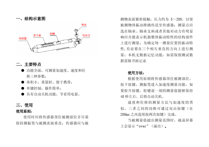
三、使用使用原则:使用时应将传感器顶住被测部位并尽量保持测振笔与被测表面垂直;传感器应与被测物表面紧密接触,压力约为5~20N,以使被测物体振动准确传送至传感器;测量点应选在轴承、轴承支座或者其他对动力有明显响应并能表示机器整体振动特性的结构部件上进行测量;为确定每一测量位置的振动特性,有必要在三个相互垂直的方向上进行测量;本机无数据记忆功能,如需保留测试数据需做书面记录使用方法:根据使用原则将传感器顶住被测部位。
按下按键,测振笔进入加速度测量功能,如果松开按键,松键前一刻的测量值能够保持40秒左右,后将自动关机。
速度和位移的测量方法与加速度的类似,三者之间的切换可通过双击按键(在200ms 之内连续按两次按键)完成。
当被测量值超出测量范围时,液晶屏幕上会显示“over”(溢出)。
四、性能指标测量参数: ● 加速度●速 度●位 移测量范围: ● 加速度:0.01 m/s2~199.9m/s2(峰值)●速 度:0.01 mm/s~199.9mm/s(有效值)●位 移:0.001 mm~1.999mm(峰~峰值)频率范围: ● 加速度:10Hz~1kHz●速 度:10Hz~1kHz●位 移:10Hz~500Hz相对误差: ● 参考灵敏度不确定度≤3%;●幅值线性相对误差±5%±2个数;●频率响应相对误差:频率在10Hz≤f<20Hz为+10-20%,频率在20Hz≤f ≤1000Hz为±5%显示方式: 3位半液晶显示,显示周期约1s供电电源: 2节扣式电池(LR44或SR44) 电池寿命:连续工作时间约4.5h,待机时间约1年使用环境:温度0ºC~40ºC;相对湿度<85%外型尺寸:150mm × 22mm × 18mm整机重量:约55g(含两节电池)五、保养维护●TV260测振仪属精密仪器,应严格避免碰撞、潮湿、强电磁场、油污及灰尘;●更换电池应注意电池正极朝向“ ”;●如果较长时间不使用,应将电池取出;●请勿随意拆卸测振笔,以免损坏内部电路。
振动电机说明书

振动电机说明书X公司振动电机使用说明书,振动电机的保养,振动电机的原理,振动电机的使用一.产品用途及使用范围MV系列振动电贾产品广泛用于冶金、矿山、煤炭、化工、电力、建材、铸造、磨料、陶瓷、玻璃、粮食、食品、医药、轻工等行业,是振动输送机、振动给料机、振动放矿机、振动干燥设备、振动筛分设备、振动落砂机、振实台、料仓振动防闭塞装置等各种振动机械设备理想的动力源和激振源。
海拔高度不超过1000米,环境温度不超过40C,相对湿度不超过90%(温度不超过2 5C时),否则应降低功率使用;主机激振工率和运行电流不超过铭牌数值,否则应降低激振力使用。
二.主体结构及工作原理振动电机由特制电机外加激振重块组成。
当电机通电旋转时,激振块产生激振力,通过电机底脚或法兰盘传递纵横振动机械。
特制电机由特制定子线包和转子轴组成,能承受高频振动;卧式振动电机采用四块扇形偏心块作激振块,调节同轴端两块偏心块的夹角,可以从零至最大调节振动电机的激振力;立式振动电机,采用两块偏心块作为激振块,两轴端各一块,上轴端为固定偏心块,下轴端为可调偏心块。
在上下偏心块的外侧各装有一组附加块,通过调节附加块的数量,可以分级调节振动电机的激振力。
振动电机通电旋转,带动电机轴两端的偏心块,产生惯性激振力,该力是空间回转力,其幅值为Fm。
Fm=mrω2m-偏心块质量r-偏心块质心回转轴心的距离,即偏心距ω-电机旋转角度频率ω=2πn/60n—振动电机振次惯性激振力通过振动电机轴承、底脚或法兰,传递给振动机械,就是该振动机械产生的激振力。
三.存放振动电机应存放在室外内,室内空气应干燥,没有不良气体,温度应在露点以上5C,相对湿度不超过50%,电机应保持平放。
储存时应对振动电机进行适当的维护,每月转动电机转子轴数转,定期查看振动电机防锈防潮状况。
四.振动电机的安装振动电机与振动机械连接平面均采用划6.3光洁度加工面,平面度应符合GB1184-79附表1的9级公差要求。
Lincoln Electric Power Wave AC DC 1000系统和相关配件介绍说明书

NX-4.180 9/05SUCCESS4/4AC/DC Submerged Arc WeldingWHAT IS NEXTWELD?The challenges facing industrial fabricators today are increasingly difficult. Rising labor, material, and energy costs, intense domestic and global competition, a dwindling pool of skilled workers,more stringent and specific quality demands.Through ourcommitment to extensive research and investments in product development,Lincoln Electric has established an industry benchmark for applyingtechnology to improve the quality, lower the cost and enhance the performance of arc welding processes.Advancements in power electronics,digital communications and Waveform Control Technology TM are the foundation for many of the improvements.NEXTWELD brings you a series ofProcess, Technology, Application and Success Story documents like this one.NEXTWELD explains how technologies,products, processes and applications are linked together to answer theimportant questions that all businesses face:•How can we work faster, smarter,more efficiently?•How can we get equipment and people to perform in ways they’ve never had to before?•How do we stay competitive?NEXTWELD is the future of welding but its benefits are available to you today. Ask your Lincoln Electric representative how to improve the flexibility, efficiency and quality of your welding operations to reduce your cost of fabrication.THE LINCOLN ELECTRIC COMPANY 1.216.481.8100“This equipment is light years ahead of the other stuff,” he said. “I’m really looking forward to the productivity we’ll get on the cell spar work. Our new design, coupled with the Power Wave technology will make us even more competitive for new projects.”Last year’s equipment transition was nearly seamless, Cortez explained. He said operators picked up the changes quickly and learned the new system with relative ease.“The changeover really didn’t slow us down at all,” he said. “There was very little learning curve, which is unusual.The team of Lincoln technicians was very helpful and many of them returned a number of times until we were dialed into the best possible settings.”Miller said that as the changeover continues and flexibility of theequipment is better understood, even more productivity will follow. “The possibilities with this technology are endless,” he said. “There’s no telling where it will take us next.”Gulf MarineFeatured Lincoln ProductsWelding for OffshoreW A V E F O R M C O N T R O L T E C H N O L O G Y ™The Power Wave AC/DC 1000 is the first power source to introduce Waveform Control Technology™ to submerged arc welding.Variable frequency and amplitude AC, DCpositive or DC negative output allows the user to control the deposition rate and penetration. An operator can increase weld speeds, yield higher quality welds and improve efficiencies in a single or multi-arc environment. The phase angle and frequency of different machines can also be synchronized to balance the interactionsbetween multiple arcs and minimize arc blow.Depending on the output, a welding arc may be driven by a single machine or multiple machines in parallel for applications that require more than 1000 amps of continuous operation.Power Wave ® AC/DC 1000。
直振控制器说明书
直振控制器说明书1、用途及适用范围1、1用途本系列电控设备与JK及JKM系列矿井提升机配套使用。
该设备可为200千瓦以上的直流电动机配套。
对提升机的启动、等速运行、制动减速、停车进行控制,并具有提升机必须的电气保护与连锁装置。
1、2适用范围(1)海拔高度不高于1000米,特别环境可特殊设计供货;(2)周围环境温度不得高于+40℃,不得低于-10℃;(3)相对湿度不超过85%;(4)没有导电尘埃及对金属和绝缘破坏作用的气体;(5)没有剧烈的振动和颠簸的场所;(6)不需防爆的场所;2、型号及主要技术特点2、1型号含义(1)单绳矿井直流提升机电控系统注:TKM(D)—天津民益电气单绳缠绕式矿井提升机电控P—可编程控制器电控系统举例:TKM/Z—D2—6408P(S)天津民益电气矿井提升机直流电控系统—电延时二级制动—主回路形式6脉动、电压等级400V、双机拖动、电枢电流800A(2)多绳摩擦轮矿井直流提升机电控系统多绳直流提升机型号编制与单绳直流提升机相同,在此不再赘述。
2、2外形及安装尺寸a、操作台外形尺寸图:b、控制柜外形尺寸图:c、高压开关柜外形尺寸图:2、3技术特点TKD(M)系列直流矿井提升机电控系统,采用PLC取代原时间继电器、速度继电器及部分中间继电器、接触器;全数自PID闭环控制软件及硬件电路替代测速发电机、给定自整角机、磁放大器系统;网络化分布式PLC 系统,采用西门子PROFIBUS总线结构CPU和分布式I/O接口模块,系统连线简单,抗干扰能力强。
本系统最大限度地实现无触点化和数字化,使矿井提升机操作和维护简单方便,使用安全可靠。
全数字直流电控系统与原模拟系统比较有如下优点:(1)采用可编程序控制器进行逻辑控制,减少元器件数量,提高可靠性。
(2)选择网络化分布式PLC产品,减少系统连线,减轻维护工作量。
(3)系统全数字化以后,参数不会发生偏移,稳定可靠大大增加。
(4)去掉了原模拟系统大量的线路板,其功能用软件实现,参数便于调解,使现场调试更加快捷。
欧诺克 直流无刷电机 产品说明书
深圳市欧诺克科技有限公司Shenzhen ONKE Technology Co., Ltd.座机:*************27381841电话:邓先生135****7106陈先生139****0920邮箱:***************网 址 : 地址:广东省深圳市宝安区福海街道怀德翠湖工业园13栋稳定的质量是我们赖以生存的根本优质的服务是我们继续发展的前提客户的满意是我们唯一追求的目标产品画册Product gallery专业生产伺服驱动器、伺服电机及自动化控制系统深圳市欧诺克科技有限公司直流无刷电机目录匠心制造精益求精“一、公司介绍01二、直流无刷电机021.电机介绍与型号说明032.电机应用领域043.电机规格参数表054.电机规格尺寸图06C O M P A N Y PROFILE以精密制造引领未来Leading the future with precision manufacturing公司简介Company Profile深圳市欧诺克科技有限公司成立于2010年,是一家专业研发生产伺服电机和驱动器的高新技术企业,公司技术力量雄厚,检测手段先进,欧诺克人本着不求最全,只求最精的信念,为生产出各类伺服电机、各类驱动器而不懈奋斗。
欧诺克人以鹰的精神,挑战尖端,研发生产出高性价比的各类伺服电机和驱动器,以鹰的敏锐洞察力洞察市场,与时俱进、创新来满足市场的需求。
深圳市欧诺克科技有限公司产品主要有:伺服驱动器、伺服电机、直流伺服驱动器,直流伺服电机,交流伺服驱动器,交流伺服电机,低压伺服驱动器,低压伺服电机,直线电机驱动器,DDR马达驱动器,音圈电机驱动器,直流无刷驱动器,直流无刷电机,CANopen总线、EtherCAT总线、电子凸轮伺服系统,大功率伺服驱动器、大电流伺服驱动器,专用运动控制伺服驱动器和自动化控制系统,十多年来凭借精湛的技术与国内国外众多知名企业公司建立了互利共赢的合作。
公司不断研究和开发满足行业需求的各类伺服电机和驱动器,帮助客户提升品质和生产效率。
振动输送机控制器FC 1000操作说明书

Integrated Feeding SystemsBetriebsanleitung Steuerung FC 1000 fürVibrationsförderer操作说明书振动输送机控制器FC 1000Inhaltsverzeichnis / 目录1HINWEISE FÜR DEN BENUTZER / 用户提示信息 (3)1.1 S ICHERHEITSHINWEISE /安全提示 (3)1.2 G EFAHRENSYMBOLE /危险标志 (3)1.3 G EFAHRENHINWEISE /危险提示信息 (4)1.4 K ONFORMITÄTSERKLÄRUNG /一致性声明 (5)1.5 B ESTIMMUNGSGEMÄßE V ERWENDUNG /按照规定使用 (5)2TECHNISCHE DATEN / 技术参数 (6)3INSTALLATION / 安装 (7)3.1 M ONTAGE /装配 (7)3.2 E LEKTRISCHER A NSCHLUSS /电子接口 (7)3.2.1Lage der Anschlüsse / 接口位置 (8)3.2.2Beschreibung der Anschlüsse / 接口名称 (8)3.2.3Anschlussbeispiel / 连接示例 (10)4OPTION E/A-MODUL / 输入/输出模块选项 (11)5INBETRIEBNAHME / 调试 (12)5.1 L AGEPLAN B EDIENELEMENTE /操作部件平面图 (12)6BEDIENUNG / 操作 (13)6.1 M ENÜSTRUKTUR /菜单结构 (13)6.2 B EDIENPHILOSOPHIE /操作原理 (14)6.3 D IE F UNKTIONSTASTEN /功能键 (14)6.3.1F1 – Systeminfo / F1 –系统信息 (14)6.3.2F2 – Setup Optionen / F2 –设置选项 (15)6.3.3F3 – Messwerte / F3 –测量值 (17)6.3.4F4 – RUN /STOP / F4 –运行 /停止 (17)6.4 T ASTENSPERRE /键锁 (18)6.5 E INSTELLUNGEN /设置 (18)6.5.1Leistung - P / 功率 - P (18)6.5.2Frequenz – F / 频率– F (19)6.5.3Sanftanlauf - Frequenz / 软启动 - 频率 (19)6.5.4Sanftanlauf - Leistung / 软启动 - 功率 (20)6.6 P ARAMETERSATZSPEICHER:/参数集存储器: (21)7FEHLER / 错误 (22)7.1 F EHLERLISTE /错误列表 (22)7.2 S ICHERUNG WECHSELN /更换保险丝 (23)1 Hinweise für den Benutzer / 用户提示信息1.1 Sicherheitshinweise / 安全提示Diese Beschreibung enthält die erforderlichen Informationen für den bestimmungsgemäßen Gebrauch der darin beschriebenen Produkte. Sie wendet sich an technisch qualifiziertes Personal.Qualifiziertes Personal sind Personen, die aufgrund ihrer Ausbildung, Erfahrung und Unterweisung sowie ihrer Kenntnisse über einschlägige Normen, Bestimmungen, Unfallverhütungsvorschriften und Betriebs-verhältnisse von dem für die Sicherheit der Anlage Verantwortlichen berechtigt worden sind, die jeweils erforderlichen Tätigkeiten auszuführen und dabei mögliche Gefahren erkennen und vermeiden können (Definition für Fachkräfte laut IEC 364). 本操作说明书含有按照规定使用所述产品的必要信息。
振动源三相异步电动机说明书
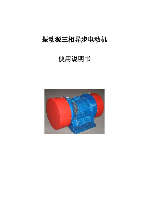
振动源三相异步电动机使用说明书一、概述振动源三相异步电动机集动力源和振动源为一体,是一种高效节能的通用性激振源,体积小,激振力大,结构合理,性能可靠,使用维修方便。
本系列产品广泛应用于矿山、煤炭、电力、化工、粮食加工、冶金、铸造、建材、轻工、医药等行业。
是实现粉状、粒状、块状等散体物料机械化筛分、输送、破碎、填充、防堵塞的理想激振源。
1、电机使用条件本系列电机满足下列条件时,能连续输出额定激振力;(1)振动加速度:不超过7g(g:重力加速度);(2)环境温度:不超过40℃;(3)海拔:不超过1000m;(4)电源频率:50Hz(5)电压:380V温升:小于80K(电阻法)2、型号说明(如下示例)例如:YZU系列产品型号由三部分组成4级)5KN)二、结构本产品是由电动机拖动偏心质体旋转而产生激振力。
电磁计算和结构设计,充分考虑到振动电机的特点,并经过优化设计,是产品性能稳定,安全可靠。
图一所示为YZU系列产品结构概图,安装时可供参考。
其外壳防护等级为IP54、IP55。
YZU系列是由YZU系列派生而来的,其安装方法与YZU系列有所不同:机座上无底脚有法兰,其安是靠法兰盘和设备配合的,其内部结构与YZU系列基本相同。
YZU系列结构示意图:序号零件名称1 防护罩2 轴3 弹性挡圈4固定偏心块5 轴承油盖6 轴承7 油咀8 端盖9 出线套10 转子铁心11 定子铁心12 吊环13 机座14 锁紧螺钉15 可调偏心块三、安装前的准备(1)检查电机铭牌是否与要求相符;(2)用500伏兆欧表测量绝缘电阻,其值应不低于0.5兆欧。
否则应对定子绕组进行干燥处理,烘干温度不能超过120℃;(3)检验电机各紧固件,谨防松动;(4)检查电机表面有无损毁、变形;(5)检查是否转动灵活,若有异常,必须及时排除;(6)检查电源是否缺相,并空载运行5分钟。
四、安装的调整(1)电机应稳固在安装面上,安装面必须光滑、平整;(2)电机可水平安装,也可倾斜安装;(3)电机引线采用四芯橡胶电缆YZ-500V,接电源时引出线电缆不允许有急折,并与振动体可靠固定;(4)电机应有可靠的接地,电机上有接地装置,引线端有标志,亦可利用底脚紧固螺栓接地;(5)激振力的调整:电机出厂时,激振力处于最大位置,若激振力过大,用户可将两端防护罩拆下,同步调节两端可调偏心块和固定偏心块间的夹角α,使激振力达到要求,如图二所示,夹角α越大,激振力越小,注意每次调节时,必须使电机两端的α角刻度大小相等,且方向一致,立式电机用增加和减少配重片的方式调整。
- 1、下载文档前请自行甄别文档内容的完整性,平台不提供额外的编辑、内容补充、找答案等附加服务。
- 2、"仅部分预览"的文档,不可在线预览部分如存在完整性等问题,可反馈申请退款(可完整预览的文档不适用该条件!)。
- 3、如文档侵犯您的权益,请联系客服反馈,我们会尽快为您处理(人工客服工作时间:9:00-18:30)。
DC-1000-13电动振动系统 使 用 说 明 书苏州试验仪器总厂STI目录1. 安全须知2. DC-1000-13 电动振动试验系统概述3. DC-1000-13 电动振动试验系统构成4. DC-1000-13 电动振动试验系统方框图5. DC-1000-13 电动振动试验系统技术参数6. 系统各组成部分详细说明6.1 SA3-13开关功率放大器6.2 DC-1000垂直振动台体7. 系统运行7.1 电动台台体部分准备7.2 传感器的安装7.3 运行操作7.4 停机8. 注意事项9. 保护动作和复位方法10. 试验样品11. 附图1. 安全须知为安全起见,请注意下述事项(由于是作一般性的说明,可能有些项目本装置中没有)。
1.1 占有区域为安全起见,在振动试验装置及电缆的四周设置一个设备占有区域(可能的话在2m2以上)。
保持占有区域清洁,不需要物品不可放在占有区域内。
占有区域以外也可能因噪音等对人体构成伤害。
除设备专门操作者,他人不可进入占有区域。
1.2 培训对本装置的操作者必须详细阅读使用说明书,有条件的进行专门培训。
1.3 检查为了您的使用安全,请作定期检查。
1.4 设置振动试验装置的主操作面板应设置在能看到振动台、功率放大器的位置。
1.5 设备电源变更电源的场合,风机、马达等可能会产生倒转现象。
请确认旋转方向,用箭头表示正确的旋转方向。
1.6 其它注意事项a. 噪声振动试验装置会产生较大的噪声,故对周围的工作人员应采取保护措施(耳塞等)。
我厂推荐隔音室作为防噪对策。
b. 机械动圈、试件、夹具等在振动时,请勿用手去触碰。
在以低频(10Hz以下)激振时,振动台台体会上下而振动,予以注意。
在安装重物(夹具、试件等)时,应非常小心。
c. 电气请不要随意打开功率放大器、控制器、振动台及其它单元的盖板,因为内部装有高压、大容量端子,可能会引起触电。
d. 温度装置内亦装有易发热部件,请不要随意打开控制面板及盖板等.e. 电缆、管道为防电缆、管道等绊脚及被踩踏,应设置保护盖或将它们置入地槽内。
f. 水、药品请不要将水、药品等洒在振动台上,因内部通有高压,会引起触电及设备故障等现象。
如因不慎,万一让水、药品等洒进振动台内部时,应及时与我厂联系。
2 DC-1000-13电动振动系统概述DC-1000-13 电动振动试验系统由 DC-1000电动台,SA3-13 开关功率放大器和FJ-1000台体冷却风机组成。
系统可以完成垂直、水平、正弦、随机等多种试验。
DC-1000电动台是由日本(IMV)公司提供图纸,按日本IMV工艺生产,按日本IMV标准检验,返销日本。
SA3-13开关功率放大器是引进技术,关键零部件进口生产。
DC-1000-13 是我厂跟踪国际先进技术,和日本国际振动研究所(IMV)公司多年合作的成果。
系统采用了当前国际电动振动试验系统制造行业一些最先进的科技成果。
如空气弹簧支撑,弹簧耳轴隔振,直线轴承导向装置。
台面行程可达 51mm ,且低频失真小,承载能力强;功率放大器采用开关方式工作,功率损耗极小,系统速度高,工作稳定可靠。
由于采用了这些先进技术,加工制造又精益求精, DC-1000-13电动振动试验系统达到了国际先进水平。
是目前日本 IMV公司销售的主系列产品。
DC-1000-13电动振动系统可以应用在电子、仪器仪表、汽车、航天航空、科学研究等领域。
型号说明D C - 1000 - 13DC 通用型51mm 电动振动台1000 1000 kgf 额定正弦推力13 13 k VA 放大器输出功率3 系统构成3.1 功率放大器部分3.1.1 功率放大器(SA3-13) 1 台3.1.2 功率放大器电缆 1 套3.2 电动台台体部分3.2.1 垂直振动台台体(DC-1000)3.2.2 振动台台体抽风机(FJ-1000) 1 台3.2.3 随机工具 1 套模块输出5 k VA 功率,组合方便,设计流畅。
SA3-13 功率放大器有三个输出模块,输出功率容量 13 kVA。
功率放大器末级用大功率MOS 场效应管并联输出,末级OTL 输出方式,使功率放大器可以直流输出。
6.1.2 功率放大器技术参数6.1.2.1 额定输出功率 13 kVA6.1.2.2 额定输出电压 90 V rms6.1.2.3 额定输出电流 100 A rms6.1.2.2 额定频率范围 5 - 3000 Hz6.1.2.5 输入信号 < 3.3 V rms6.1.2.6 输入阻抗 > 10 kΩ6.1.2.7 励磁电压 240 VDC6.1.2.8 励磁电流 30 ADC6.1.3 SA3-13功率放大器SA3-13功率放大器机柜装有SA-100 系统控制箱,一个SA-250/3 功率输出单元、电源和电气控制单元。
功率放大器和各组成单元的安装关系如下图:让台体充分冷却。
6.1.4.3 OUTPUT OVER VOL。
AND OUTPUT OVER CURR。
输出过电压和输出过电流指功率放大器输出电压或功率放大器输出电流超过允许值时,功率放大器保护电路工作,切断输入信号,同时用发光二极管指示原因。
6.1.4.4 POWER SUPPLY OVER CURR.、HIGH VOL.、LOW VOL.电源过电流、高电压、低电压功率放大器直流电源输出电流过大、电源直流电压过高、电源直流电压过低。
6.1.4.5 SYSTEM OVER DIP.、OVER HEAT、FIELD SUPPLY、FUSE、 THERMAL、OTHER AND EXT。
STOP系统过位移、过热、励磁电源、保险丝、热继电器、其他 和外部停机。
系统振动时台面位移超过 51mm 、台体温度过高或功率放器温度过高、励磁电源异常、电源部分保险丝熔断、热继电器动作。
其他和外部停机给用户接入自己的联动信号。
6.1.4.6 STATUS LINE、COOLING、OPERATION、COMI.工作状态:电源、冷却、运行、复合当漏电断路器合上 ,LINE 灯亮,指示系统已经上电,此时控制箱已经有电。
当按下 POWER ON 开关时,数秒后冷却风机转动,COOLING 指示灯亮;数秒后,励磁电源上电,功率放大器的功率放大级上电,OPERATION 指示灯亮系统进入工作状态,只要加入信号系统就可以工作。
此一切都是自动进行的。
6.1.4.7 GAIN AND RESET带复位开关的增益电位器增益电位器可以调节输入信号大小,开机和关机前增益电位器必须到RESET位置,OPERATION灯亮后,增益电位器顺时针旋到最大位置。
当 某种原因功率放大器跳闸,TRIP灯亮时,增益电位器逆时针旋到RESET 位置,起复位作用。
6.1.4.8 INPUT SELECT输入信号选择开关输入信号可以选择A、B两个同轴插座,A在机柜系统控制器的后面板,B在系统控制器的前面板上。
本台机器设定上架振动控制仪从A插座输入,外接振动控制仪从B插座输入。
可以通过此开关选择转换。
注意:功率放大器工作时,请不要进行选择。
6.1.4.9 EMERGENCY紧急开关当功率放大器、振动台或试验样品发生异常时,可以按下此开关。
按下此开关直接断开漏电断路器,切断整个功率放大器电源,所以 TRIP 指示灯并不亮。
复位方法:漏电断路器开关置于OFF状态,增益电位器置于RESET位置,信号源或控制器的输出信号电位器逆时针旋到头。
再按部就班地重新起动机器。
注意:系统正常时请不要用此开关来进行开关机。
6.1.5 SA-250 功率输出单元功率输出单元的作用是放大输出功率。
功率输出单元由三组功率输出摸块组成,每个模块输出功率是5kW,由20只MOS场效应管组成桥式输出,输出功率容量是13kVA。
功率输出单元有两只小冷却风机,用来冷却功率管,由于开关功率放大器效率较高,两只小冷却风机已绰绰有余.移去功率输出单元的面板可以看见每个功率输出单元有8只发光二极管,用来指示功率输出单元的工作状况。
如果发光二极管灯亮,说明熔断丝熔断或有功率管损坏,或风既有故障,应该停止工作,与制造厂联系更换熔断丝或功率管或清理风机。
电压过高原因,排除。
LOW VOLT。
直流电源电压过低。
电源电压过低,使得功率输出级的电源电压低于设定值。
寻找电源电压过低原因, 排除。
注意:任何故障如果找不出原因,请与我厂联系,不要自行修理,以免扩大故障。
SYSTEMOVER HEAT 过热。
振动台台体励磁线圈温度超过110 ℃或者室温40℃。
请检查台体风机运转是否正常,通风道是否畅通无阻,通风管是否扁了。
注意:风机每次重新接线后,或电源线重新接过后,都应检查风机 转向。
FIELD SUPPLY 励磁电路不正常。
励磁电源保险丝熔断。
检查保险丝熔断原因,更换保险丝或者与我厂联系。
FUSE THERMAL 熔断器熔断或热继电器保护。
流过热继电器或熔断器的电流过大的电流过大,超过设定值。
确定 是哪个热继电器动作或熔断器熔断,寻找原因,排除故障。
排除后手工复位。
或与我厂联系。
OTHERS 其他保护联动。
本系统没联接。
EXT、STOP 外部设备接入的停止信号。
例如可以接入温度箱联动信号6.2 DC-1000 振动台台体6.2.1 概述DC-1000 振动台台体利用恒定磁场中对线圈通以电流,线圈就会产生运动的原理。
对恒定磁场中的线圈通以交变电流,线圈就产生交变运如果传感器接头有水浸入,必须用防水密封膏密封联接部。
7.3 操作作请仔细7.3.1 控制仪或者信号源输出电位器关到零。
控制仪的操阅读正弦振动控制仪和随机振动控制仪的使用说明书。
7.3.2 SA3-13功率放大器的增益电位器开关选择到RESET位置。
打开振动控制仪或信号源的电源。
7.3.3 SA-100的INPUT SELECT如果上架振动控制仪选择A;外接振动控制仪选择B。
7.3.4 水平振动时,打开油泵电源,等5分钟。
7.3.5 功率放大器正面漏电断路器合和上。
此时上架振动控制仪上电;SA-100面板上的LINE指示灯亮.7.3.6 功率放大器控制箱面板 POWER ON 按钮按下。
数秒后,功率放大器冷却风扇和振动台冷却风机运转,COOLING指示灯亮;再数秒后,励磁电源工作,电压加到励磁线圈;再数秒后,功率放大器末级上电.OPERATE 指示灯亮. 这一切都是自动进行的,只要轻轻地一按。
此时系统处于工作状态。
注意:首次开机或移动后再安装的设备,或重新联接电源,请检查 风机转向.如果转向不正确,请交换电源线接头.7.3.7 SA-100面板上的增益电位器顺时方向针旋到最大.慢慢地打开控制仪或信号源输出电位器,台面上应有相应的振动。
7.4 停机7.4.1 功率放大器SA-100面板上的增益电位器逆时针旋到RESET 位置。
