Arduino教程英文版
Arduino使用教程
时间函数 Arduino 使用教程
梦工厂
北京龙凡汇众机器人科技有限公司 E_mail: service@
Arduino 使用教程
http://
DreamFactory
5
• unsigned long millis() 返回时间函数(单位 ms),该函数是指,当程序运行就开始计时并返回记录的参数, 该参数溢出大概需要 50 天时间。
• unsigned long pulseIn(pin, value) 脉冲长度记录函数,返回时间参数(us),pin 表示为 0~13,value 为 HI GH 或 LOW。比如 value 为 HIGH,那么当 pin 输入为高电平时,开始计时,当 pin 输入为低电平时,停止计 时,然后返回该时间。
• int digitalRead(pin) 数字 IO 口读输入电平函数,pin 表示为 0~13,value 表示为 HIGH 或 LOW。比如可以 读数字传感器。
模拟 I/O
• int analogRead(pin) 模拟 IO 口读函数,pin 表示为 0~5(Arduino Diecimila 为 0~5,Arduino nano 为 0~7)。 比如可以读模拟传感器(10 位 AD,0~5V 表示为 0~1023)。
语法符号:
•; • {} • // • /* */
运算符:
•= •+ ••* •/ •% • == • !=
Arduino 使用教程
梦工厂
北京龙凡汇众机器人科技有限公司 E_mail: service@
Arduino 使用教程
•< •> • <= • >= • && • || •! • ++ • -• += • -= • *= • /=
Arduino使用教程和典型范例

扩展 I/O
gh 与 toHigh 之间。
• pow(base, exponent) 开方函数,base 的 exponent 次方。 • sq(x) 平方 • sqrt(x) 开根号
三角函数
• sin(rad) • cos(rad) • tan(rad)
随机数函数
• randomSeed(seed) 随机数端口定义函数,seed 表示读模拟口 analogRead(pin)函数 。 • long random(max) 随机数函数,返回数据大于等于 0,小于 max。 • long random(min, max) 随机数函数,返回数据大于等于 min,小于 max。
Arduino 使用教程
梦厂
北京龙凡汇众机器人科技有限公司 E_mail: service@
Arduino 使用教程
http://
第一课 Arduino 语言
DreamFactory
2
Arduino 语言是建立在 C/C++基础上的,其实也就是基础的 C 语言,Arduino 语言只不过把 AVR 单片机(微控制 器)相关的一些寄存器参数设置等都函数化了,不用我们去了解他的底层,让不太了解 AVR 单片机(微控制器)的 朋友也能轻松上手。
arduinoccenreferencelibrarieseepromeeprom读写程序库ethernet以太网控制器程序库liquidcrystallcd控制程序库servo舵机控制程序库softwareserial任何数字io口模拟?口程序库stepper步进电机控制程序库wiretwii2c总线程序库matrixled矩阵控制程序库spriteled矩阵图象处?控制程序库第二课arduino的数字模拟端口arduino控制器内带bootloader程序是系统上电后运?的第一段代码就好比pc机bios中的程序启动就进?自检配置端口等等当然单片机就是靠烧写熔丝位来设定上电从boot区启动的使用这个程序就可以直接把从?口发来的程序存放到flash区中
Arduino手把手入门教程Arduino入门教程

Arduino⼿把⼿⼊门教程Arduino⼊门教程简单说,Arduino是⼀块AtmegaX8的开发板,带BootLoader,通过USB转串⼝和电脑通信。
Arduino把AtmegaX8的功能做了简化,以⽅便开发,并提供完整的IDE开发环境。
Arduino在国外⾮常⽕,主要⽤来做【互动多媒体】,因为从事【互动多媒体】多半是⽂科⽣,所以功能尽可能的简化。
⼯程师级别的对Arduino不感冒,认为Arduino侮辱了他们的智商。
实际上Arduino对最⼤的强项是提供了丰富的库资源,⼏乎任何外设,是要在google上敲⼊关键字 + Arduino,就可以得到你想要的。
例如:google输⼊:PCF8574 ArduinoArduino是⼀块简单、⽅便使⽤的通⽤GPIO接⼝板,并可以通过USB接⼝和电脑通信。
作为⼀块通⽤IO接⼝板,Arduino提供丰富的资源,包括:13个数字IO⼝(DIO数字输⼊输出⼝);6个PWM输出(AOUT可做模拟输出⼝使⽤);5个模拟输⼊⼝(AIN模拟输⼊)。
Arduino开发使⽤java开发的编程环境,使⽤类c语⾔编程,并提供丰富的库函数。
Arduino可以和下列软件结合创作丰富多彩的互动作品:Flash,Processing,Max/MSP,VVVV…等。
Arduino也可以⽤独⽴的⽅式运作,开发电⼦互动作品,例如:开关控制Switch、传感器sensors输⼊、LED等显⽰器件、各种马达或其它输出装置。
Arduino特⾊1. Arduino的IDE是免费、开源的。
2. Arduino的硬件也是开源的,包括原理图和PCB图。
3. Arduino的所有资源都可以免费下载,并且可依需求⾃⼰修改!4. Arduino的附件只需1根USB线,编程、烧写⼀键搞定。
5. Arduino使⽤低价格、容易购买的微处理控制器ATMEGA168。
6. ⽀持多种互动软件:Flash,Max/Msp,VVVV,PD,Processing等。
Arduino电路控制入门教程

Arduino电路控制入门教程第一章:Arduino简介Arduino是一款开源电子平台,将硬件和软件相结合,用于创建各种电子项目。
它基于开放式软、硬件设计,非常适合初学者和专业人士。
Arduino的优势在于其易用性、可扩展性和灵活性,使其成为学习和实践电路控制的理想工具。
第二章:Arduino基础知识2.1 Arduino硬件组成Arduino主板包括一个微控制器,具有多个数字和模拟输入/输出引脚。
此外,还有一个USB接口用于与计算机通信,以及用于供电和编程的连接器。
2.2 Arduino编程语言Arduino使用C/C++编程语言,开发者可以使用Arduino IDE (集成开发环境)进行编码。
Arduino语言基于Wiring语言,具有简单易学的特点,适合初学者。
第三章:Arduino基本操作3.1 安装Arduino IDE下载Arduino IDE并根据安装向导进行安装。
启动IDE后,用户可以选择Arduino板型及端口。
3.2 第一个Arduino项目编写一个简单的程序来控制Arduino上的LED灯。
使用digitalWrite函数控制引脚的电平,通过设置为HIGH或LOW来打开或关闭LED灯。
第四章:数字输入与输出4.1 数字输入使用digitalRead函数读取数字输入引脚上的状态。
通过判断引脚为HIGH还是LOW,可以实现不同的应用,如按键检测或传感器数据获取。
4.2 数字输出使用digitalWrite函数控制数字输出引脚的状态。
通过设置引脚为HIGH或LOW,可以控制外部电路的开关状态,实现各种控制任务。
第五章:模拟输入与输出5.1 模拟输入Arduino具有一些模拟输入引脚,可以通过analogRead函数读取引脚上的模拟电压值。
这对于读取传感器数据或监测环境变量非常有用。
5.2 模拟输出Arduino可以通过PWM(脉宽调制)方式在数字输出引脚上生成模拟电压。
analogWrite函数可以设置引脚上的占空比,从而控制输出电平的变化。
Arduino教程(非常适合初学者)

Arduino教程一: 数字输出Arduino, 教程11 Comments »Arduino的数字I/O被分成两个部分,其中每个部分都包含有6个可用的I/O管脚,即管脚2到管脚7和管脚8到管脚13。
除了管脚13上接了一个1K的电阻之外,其他各个管脚都直接连接到ATmega上。
我们可以利用一个6位的数字跑马灯,来对Arduino数字I/O 的输出功能进行验证,以下是相应的原理图:电路中在每个I/O管脚上加的那个1K电阻被称为限流电阻,由于发光二极管在电路中没有等效电阻值,使用限流电阻可以使元件上通过的电流不至于过大,能够起到保护的作用。
该工程对应的代码为:int BASE = 2;int NUM = 6;int index = 0;void setup(){for (int i = BASE; i < BASE + NUM; i ++){pinMode(i, OUTPUT);}}void loop(){for (int i = BASE; i < BASE + NUM; i ++) {digitalWrite(i, LOW);}digitalWrite(BASE + index, HIGH);index = (index + 1) % NUM;delay(100);}下载并运行该工程,连接在Arduino数字I/O管脚2到管脚7上的发光二极管会依次点亮0.1秒,然后再熄灭:这个实验可以用来验证数字I/O输出的正确性。
Arduino上一共有十二个数字I/O管脚,我们可以用同样的办法验证其他六个管脚的正确性,而这只需要对上述工程的第一行做相应的修改就可以了:int BASE = 8;SEP01Arduino教程二: 数字输入Arduino, 教程3 Comments »在数字电路中开关(switch)是一种基本的输入形式,它的作用是保持电路的连接或者断开。
Arduino从数字I/O管脚上只能读出高电平(5V)或者低电平(0V),因此我们首先面临到的一个问题就是如何将开关的开/断状态转变成Arduino能够读取的高/低电平。
第二十课---Arduino-教程---Arduino-Due-和-Zero

Zero应用程序涵盖从智能物联网设备,可穿戴技术,高科技自动化,到疯狂的机器人技术。
该板采用Atmel的SAMD21 MCU供电,该MCU配有32位ARMCortex®M0 +内核。
其最重要的特性之一是Atmel的嵌入式调试器(EDBG),它提供了一个完整的调试接口,无需额外的硬件,显着提高了软件调试的易用性。
该板包含了支持微控制器所需的一切。你可以使用micro-USB电缆将其连接到计算机,或者使用AC-to-DC适配器或电池为其供电以启用。Due与所有工作在3.3V电压的Arduino盾板兼容。
Arduino Zero
Zero是由UNO建立的平台的简单而强大的32位扩展。Zero板通过提供更高的性能扩展其系列,为设备提供各种项目机会,并成为学习32位应用程序开发的绝佳教育工具。
该板包含支持微控制器所需的一切。你可以使用micro-USB电缆将其连接到计算机,或者使用AC-to-DC适配器或电池为其供电以启用。Zero与所有工作在3.3V电压的盾板兼容。
Arduino进阶
Arduino进阶
1.Arduino Due和Zero
2.Arduino脉冲宽度调制
3.Arduino随机数
4.Arduino中断
5.Arduino通信
6.Arduino内部集成电路
7.Arduino串行外设接口
第二十课
Arduino Due是基于Atmel SAM3X8E ARM Cortex-M3 CPU的微控制器板。它是第一款基于32位ARM内核微控制器的Arduino板。
EDBG还支持可用于器件和引导加载程序编程的虚拟COM端口。
Arduino Zero
工作电压
CPU速度
Arduino入门教程(1)—驱动安装及下载Blink程序

Arduino 入门教程(1)—驱动安装及下载 Blink 程序拿到了盼望已久的 Arduino 入门套件是不是有立马想试一试的冲动,但。
同样又面对不知如何下手的困扰呢?我们这里就从头开始教大家。
那就开始吧!STEP 1:下载 Arduino I DE打开网页输入网址/en/Main/SoftwareArduino IDE 老版本下载链接:/en/Main/OldSoftwareReleases进入到页面后,找到下图显示部分。
Windows 用户,点击下载Windows(ZIPfile),如果 Mac,Linux 用户则选择相应的系统。
下载完成后,解压文件,把整个 Arduino 1.0.5 文件夹放到你电脑熟悉的位置,便于你之后查找。
打开 Arduino1.0.5 文件夹,就是下图看到的内容。
STEP 2 : 安装驱动把 USB 一端插到 UNO 上,另一端连到电脑。
连接成功后,UNO 板的红色电源指示灯 ON 亮起。
然后,打开控制面板,选择设备管理器。
找到其它设备-->Arduino-xx,右击选择更新驱动程序软件。
在弹出的对话框中选择下面一项--> 手动查找并安装驱动程序软件。
打开到 Arduino IDE 安装位置,就是上面那个解压文件的位置,选择搜索路径到 drivers,点击下一步。
选择始终安装此驱动程序软件,直至完成。
出现下图,说明驱动安装成功。
此时,设备管理器端口会显示一个串口号。
帖子最后罗列了一些驱动安装可能遇到的问题!STEP 3 : 认识 Arduino I DE打开 Arudino IDE,就会出现 Arduino IDE 的编辑界面。
如果英文界面,你不太习惯的话,可以先更改为中文界面。
选择菜单栏 File --> Preferences。
会跳出下面这个对话框,选择 Editor language --> 简体中文,点击 OK。
关闭 Arduino IDE,重新打开,就是中文界面了!先简单认识看一下 Arduino 的这个编译器,以后可是要经常和它打交道的。
Arduino 教程--第三十三课 Arduino 鼠标按钮控制
第三十三课Arduino 鼠标按钮控制
使用鼠标库,你可以使用Arduino Leonardo,Micro或Due来控制计算机的屏幕光标。
这个特殊的例子使用五个按钮来移动屏幕上的光标。
四个按钮是方向性的(上,下,左,右),一个是用于鼠标左键单击。
来自Arduino的光标移动总是相对的。
每次读取输入时,光标的位置都会相对于当前位置进行更新。
只要有一个方向按钮被按下,Arduino就会移动鼠标,在合适的方向上将HIGH输入映射到5的范围。
第五个按钮用于控制来自鼠标的左键单击。
当按钮被释放时,计算机将识别事件。
必需的组件
你将需要以下组件:
∙ 1 × Breadboard 面包板
∙ 1 × Arduino Leonardo, Micro 或Due板
∙ 5 × 10k欧姆电阻
∙ 5 ×瞬时按钮
程序
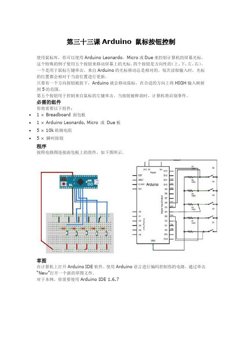
按照电路图连接面包板上的组件,如下图所示。
草图
在计算机上打开Arduino IDE软件。
使用Arduino语言进行编码控制你的电路。
通过单击“New”打开一个新的草图文件。
对于本例,你需要使用Arduino IDE 1.6.7
Arduino代码
代码说明
使用micro-USB线将电路板连接到计算机。
按钮连接到引脚2至6的数字输入。
确保使用10k下拉电阻。
Arduino-教程-第29课-Arduino-读取模拟电压

第29课Arduino 读取模拟电压此示例将向你展示如何读取模拟引脚0上的模拟输入。
输入从analogRead()转换为电压,并打印输出到Arduino软件(IDE)的串口监视器。
必需的组件你将需要以下组件:∙ 1 × Breadboard 面包板∙ 1 × Arduino Uno R3∙ 1 × 5K可变电阻(电位器)∙ 2 ×跳线程序按照电路图连接面包板上的组件,如下图所示。
电位器电位器是一种简单的机电传感器。
它将来自输入操作器的旋转或线性运动转换为电阻的变化。
这种变化是(或可以)用于控制任何东西,从高保真音响系统到巨大的集装箱船的方向。
我们知道电位器最初被称为变阻器(本质上是一个可变的绕线电阻)。
现在可用的电阻器的种类现在相当惊人的,而初学者(特别是)可能很难确定哪种类型适合于给定的任务。
一些不同的电阻器类型,都可以用于相同的任务,使得确定工作更难。
左边的图像显示电阻器的标准原理图符号。
右边的图像是电位器。
草图在计算机上打开Arduino IDE软件。
使用Arduino语言进行编码控制你的电路。
通过单击“New”打开一个新的草图文件。
Arduino代码代码说明在下面给出的程序或草图中,你在设置功能中做的第一件事是在你的电路板和你的电脑之间以9600比特每秒开始串行通信,使用以下代码:在代码的主循环中,你需要建立一个变量来存储来自电位器的电阻值(其范围在0到1023之间,非常适合int数据类型):要将值从0-1023更改为与引脚正在读取的电压相对应的范围,你需要创建另一个变量,一个浮点数并进行一些计算。
要缩小0.0和5.0之间的数字,将5.0除以1023.0,再乘以sensorValue:最后,你需要将此信息打印到串行窗口。
你可以用最后一行代码中的Serial.println()命令:现在,通过单击顶部绿色栏右侧的图标或按Ctrl+Shift+M打开Arduino IDE中的串口监视器。
Arduino教程

Arduino教程Arduino LWZ 教程V1.0目录一、Arduino编程语言 (4)1、数据类型: (4)2、常量: (4)3、基本语句: (4)(1)if语句 (4)(2)if...else...语句 (5)(3)for语句 (5)(4)break和continue (6)(5)switch case语句 (6)(6)while语句和do...while语句 (7)(7)return语句 (8)(8)运算符 (8)(9)函数 (8)4、结构函数: (8)5、功能函数: (9)(1)数字I/O函数 (9)(2)模拟I/O函数 (9)(3)时间函数 (9)(4)数学函数 (10)(5)数据类型转换函数 (10)(6)三角函数 (10)(7)随机数函数 (10)(8)外部中断函数 (11)(9)中断使能函数 (11)(10)串口收发函数 (11)6、官方库文件: (11)二、Sabertooth电机驱动模块应用实例 (13)1、工作模式 (13)(1)Mode1: Analog Input (13)(2)Mode2:R/C Input (14)(3)Mode3:Simplified serial (14)(4)Mode4:Packetized serial (15)2、应用实例 (17)(1)硬件连接 (17)(2)小车停止函数 (18)(3)小车前进函数 (19)(4)小车后退函数 (19)(5)小车右转函数 (20)(6)小车左转函数 (21)(7)电子积木编程思路 (22)(8)PC软件的编程思路 (25)(1)硬件连接 (25)(2)电子积木运动和初始化函数 (25)(3)电子积木编程思路 (26)4、通过无线模块控制小车 (28)(1)无线通信模块 (28)(2)硬件连接 (28)(3)电子积木编程思路 (28)5、下载程序串口COM和无线数模串口COM2同时控制小车 (30)(1)硬件连接 (31)(2)电子积木编程思路 (31)三、TN901_TEST非接触测温模块应用实例 (34)1、TN901工作原理 (34)2、应用实例 (36)(1)硬件连接 (36)(2)读取温度函数 (36)(3)初始化函数 (38)(4)电子积木编程思路 (38)3、多个TN模块的应用实例 (39)(1)硬件连接 (39)(2)初始化函数 (39)(3)电子积木编程思想:共享函数 (40)(4)电子积木编程思路:独立函数 (42)四、气体传感器模块应用实例 (46)1、应用实例 (46)(1)硬件连接 (46)(2)电子积木编程思路 (46)2、多个气体传感器的应用实例 (47)(1)硬件连接 (47)(2)电子积木编程思路 (47)五、火焰传感器模块应用实例 (48)1、应用实例 (48)(1)硬件连接 (48)(2)电子积木编程思路 (49)2、多个火焰传感器的应用实例 (49)(1)硬件连接 (49)(2)电子积木编程思路 (50)六、DF-miniLTV3寻线模块应用实例 (50)1、DF-miniLTV3寻线工作原理 (50)2、DF-miniLTV3寻线在单黑线的应用实例 (51)(1)硬件连接 (52)(2)Sabertooth模块函数 (52)(3)初始化函数 (52)(4)电子积木编程思路 (52)(1)硬件连接 (54)(2)电子积木编程思路 (54)(2)PC软件的编程思路 (56)七、舵机模块应用实例 (56)1、舵机工作原理 (56)2、应用实例 (57)(1)硬件连接 (57)(2)电子积木编程思路 (57)3、非库形式的应用实例 (59)(1)硬件连接 (59)(2)双舵机驱动函数 (59)八、综合实例 (63)1、驱动2台舵机和电机的应用实例 (63)(1)硬件连接 (63)(2)电子积木编程思路 (64)2、测3个测温度、驱动电机的应用实例 (64)(1)硬件连接 (64)(2)电子积木编程思路 (64)3、测3个测温度、驱动2台舵机和电机的应用实例 (65)(1)硬件连接 (65)(2)电子积木编程思路 (65)4、测2个气体、2个火焰、3个测温度、驱动2台舵机和电机的应用实例 (65)(1)硬件连接 (65)(2)电子积木编程思路 (65)5、寻线、测2个气体、2个火焰、3个测温度、驱动2台舵机和电机的应用实例 (66)(1)硬件连接 (66)(2)电子积木编程思路 (66)一、Arduino编程语言Arduino语言是建立在C/C++基础上的。
《ARDUINO教程》课件

四、项目实战
闪烁的LED灯
实现一个简单的LED 灯闪烁效果,巩固基 础的数字输出控制。
数码管显示
学习如何驱动数码管, 显示数字、字符,实 现有趣的计数和文字 效果。
温度传感器读 取并显示
使用温度传感器读取 环境温度,然后通过 电子屏幕显示温度数 值。
震动开关控制 LED
利用震动开关传感器 的信号,控制LED灯 的开关状态,实现震 动检测功能。
Arduino的优势
Arduino具有易学易用、成本低廉、丰富的社区 支持和丰富的资源等优势。
常见的Arduino板型
Arduino Uno、Arduino Mega、Arduino Nano等是 最常见的Arduino开发板。
二、基础
1
Arduino编程语言
使用C/C++语言进行编程,简洁易学,与其他语言的转换也相对容易。
五、总结
1 Arduino的优势和局限性
总结Arduino的优点和限制,帮助学习者更好地理解和使用Arduino。
2 下一步学习路线
引导学习者进一步学习其他电子技术和创客领域,拓宽知识和技能。
3 Q&A
留出时间解答学习者对Arduino的疑问,加强交流和互动。
2
Arduino集成开发环境(IDE)
Arduino IDE是一个简单易用的软件工具,用于编写和上传代码到Arduino开发板。
3
硬件连线
学习如何正确连接电子元件,包括电阻、LED、按钮等,建立电路并与Arduino进行交互。
4
数字输入输出
了解数字引脚的输入和输出操作,控制LED灯、蜂鸣器等设备。
5
《ARDUINO教程》PPT课 件
Arduino开发板入门教程

Arduino开发板入门教程第一章:Arduino简介Arduino是一款开源硬件平台,广泛应用于物联网、机器人和自动化领域。
它由一个简单易用的硬件开发板和一个基于Java的集成开发环境(IDE)组成。
本章将介绍Arduino的基本知识和原理。
1.1 Arduino开发板的组成Arduino开发板包含一个微控制器、一组输入输出引脚和一些其他的电子元件。
常用的Arduino型号有Arduino Uno、Arduino Nano和Arduino Mega等。
1.2 Arduino的特点和应用Arduino具有开源、低成本、易使用和可扩展的特点,使其成为广大电子爱好者和创客的首选。
它可以用于建造简单的电子装置、控制传感器、驱动电机以及与计算机进行通信等。
第二章:Arduino的基本用法本章将详细介绍Arduino的基本用法,包括设置Arduino开发环境、编写代码、上传程序以及与外部电路的连接。
2.1 Arduino开发环境的安装与设置首先,需要从Arduino官方网站上下载并安装Arduino集成开发环境(IDE)。
安装完成后,用户需要选择合适的开发板和端口。
2.2 Arduino编程基础Arduino使用一种类似C语言的编程语言。
本节将介绍Arduino编程的基本结构、语法和常用函数。
同时,还将介绍数字输入/输出、模拟输入/输出和串口通信等常用功能。
2.3 Arduino程序的上传编写好的Arduino程序需要通过USB接口将代码上传到开发板上。
本节将介绍如何将程序上传到Arduino开发板,并进行调试和测试。
2.4 Arduino与外部电路的连接Arduino开发板上有多个数字引脚和模拟引脚,可以与外部电路进行连接。
本节将介绍如何使用面包板和杜邦线将Arduino与LED、电位器、温度传感器等外部元件进行连接,并通过编写程序进行控制和读取。
第三章:Arduino的高级用法在本章中,将介绍一些Arduino的高级应用,包括使用库函数、扩展Arduino功能以及与其他设备的通信等。
Arduino-教程-第22课-Arduino-随机数

第22课Arduino 随机数
要生成随机数,可以使用Arduino随机数函数。
我们有两个函数:
∙randomSeed(seed)
∙random()
randomSeed(seed)
randomSeed(seed)函数重置Arduino的伪随机数生成器。
虽然random()返回的数字的分布本质上是随机的,但是顺序是可预测的。
你应该将发生器重置为某个随机值。
如果你有一个未连接的模拟引脚,它可能会从周围环境中拾取随机噪音。
这些可能是无线电波,宇宙射线,手机的电磁干扰,荧光灯等。
例子
random()
random函数生成伪随机数。
以下是语法。
random()语法
例子
让我们现在重温我们对一些基本概念的知识,例如位和字节。
Bit(位)
位只是一个二进制数字。
∙二进制系统使用两个数字,0和1。
∙与十进制数字系统类似,数字的位数不具有相同的值,位的“意义"取决于其在二进制数中的位置。
例如,十进制数666中的数字相同,但具有不同的值。
字节
一个字节由8位组成。
∙如果一个位是一个数字,逻辑上字节表示数字。
∙可以对它们执行所有数学运算。
∙一个字节中的数字也不具有相同的意义。
∙最左边的位具有被称为最高有效位(MSB)的最大值。
∙最右边的位具有最小值,因此称为最低有效位(LSB)。
由于可以以256种不同的方式组合一个字节的八个0和1,所以可以由一个字节表示的最大十进制数是255(一个组合表示零)。
Arduino入门教程(3)—做一个S.O.S求救

Arduino 入门教程(3)—做一个S.O.S 求救简单回顾下 Lesson 2 的内容:如何使用面包板电阻的作用LED 相关知识STEP 1:还原 Lesson 2 的硬件电路这次将继续使用 Lesson 2 的搭建的电路,但我们这里将改变一下代码,就能让 LED 变为 S.O.S 求救信号了。
这是国际莫尔斯码求救信号。
莫尔斯码是一种字符编码,英文的每个字母,都是由横杠和点不同的组合而成。
这样的好处是,使用简单的两种状态,就能来传递所有的字母和数字,非常的简便!可以通过 LED 开关两种状态来拼出一个个字母。
长闪烁和短闪烁来表示点和横杠。
就拼写 S.O.S 这三个字母。
通过查阅莫尔斯码表,可以知道,字母“S”用三个点表示,我们这里用短闪烁替代,字母“O”则用三个横杠表示,用长闪烁替代。
有 Lesson 1 和 Lesson 2 的基础,不难理解下面这段代码吧!1. int ledPin = 10;2. void setup() {4. }5. void loop() {digitalWrite(ledPin,LOW);delay(100);14.15. 16.21.27.32.37.48.53. }STEP 2:输入代码上面的写法固然正确,可是是不是觉得有点繁琐呢?如果有个100 个,难不成还重复 100 遍吗?有没有更好的书写程序的方法呢?想必发明编程的人也考虑到这个问题了,所以有了我们更好的一种写法。
我们先来看一下下面这段代码。
1. int ledPin = 10;2. void setup() {4. }5. void loop() {16.24.35.38. }在输入代码的时候,注意保持代码的一个层次感,除了美观外,也便于你日后检 查代码。
确认正确后,下载代码到 Arduino 中,如果一切顺利的话,我们将看 到 LED 闪烁出莫尔斯码 S.O.S 信号,等待 5 秒。
重复闪烁。
给 Arduino 外接电 池,整个装到防水的盒子里,就可以用来发 S.O.S 信号了。
arduino数字io口控制四个舵机(英文)

Hardware SetupHardware for this project consists of an Arduino module, four JR Sport ST47 standard servos, and a breadboard to create the circuit.The servos each have three wires: Ground (brown), Power (red) and Control (yellow). Each of the Control wires will connect to a different digital pin on the Arduino board (pins 2 through 5 in our setup), and all of the Power and Ground wires will need to connect somehow to the 5V and Gnd pins.The simplest way to accomplish this is to create a “bus” bar along one of the breadboard’s edges, as shown in the photo above. Simply route the Arduino’s 5V and Gnd to a convenient area on the breadboard, and connect all the servos.Required Software: The Lower LayersTo get the effects seen in t he video above, you’ll need at least the following two programs. Although this code is designed to control four servos, it also works as-is with fewer servos, and — with a few modifications — as many as twelve.Download the code:MultipleServos.pde: This is the Arduino sketch. Copy and paste this code into your Arduino IDE software and upload it to the board.servo.py: This is the Python module which talks directly to the Arduino sketch “MultipleServos.” This script requires the pyserial module, available from Sourceforge. Save this script on your PC wherever you like, just be sure to name it “servo.py”.New to Python?Welcome! Python is a versatile and fun language to learn, and it’s used by just about everyone, from newbies to NASA! Check out the Beginner’s Guide to get your bearings, or get the full skinny at .Customize the code:Depending on your computer system and Arduino hardware setup, you may need to make a few modifications to the code.Arduino:In the “MultipleServos” sketch, take note of the following three variables and make adjustments as necessary for your setup. See “Arduino Serial Servo Control” for more details regarding the minPulse and maxPulse variables.int pinArray[4] = {2, 3, 4, 5}; // digital pins for the servosint minPulse = 600; // minimum servo positionint maxPulse = 2400; // maximum servo positionPython:In the “servo.py” script, you’ll most likely need to change the value of the usbport variable, which tells Python how to find your Arduino (On Windows, it’ll be something like ‘COM5′. On a Mac,‘/dev/bserial-xxxxx’. On Linux, ‘/dev/ttyUSB0′.). Try running ls /dev/tty* from a Mac or Linux terminal for a list of available ports. [ToDo: Modify the script to make this step unnecessary.]Test the code:Once your hardware is set up and the software is installed, you can test the system’s basic functionality from the Python interactive interpreter, like so:~/path/to/servo.py$ python>>> import servo>>> servo.move(2,150)The servo.move() method takes two arguments, both integers. The first is the servo number you wish to move, 1-4. The second is the commanded angular position of the servo horn, from 0-180 degrees. So, if you want to move Servo #3 fully clockwise (180 degrees), you’ll type servo.move(3,180). Cake, baby!Optional Software: From Totally Geek to Totally ChicThe following scripts are designed to leverage the functionality of the servo.move() method for simple and readable code. Make sure these files reside in the same directory as “servo.py”.∙servodance.py: A cascading effect that feels like watching a quarter spiral down one of those funnel-shaped wishing wells.∙multijoystick.py: Allows joystick control of the servos, with each joystick axis controlling a single servo. This code could the basis for a Wi-Fi RC vehicle of some kind.∙servorandom.py: The final servo sequence seen in the video, with individual servos moving to random positions and then waving“goodbye” in unison.With any luck, you should now have everything up and running just like in the video!Part II: Getting Down to Brass TacksNext, let’s take a look under the hood to see how it all works. If you’re the type that just wants to get things working and damn the details, STOP HERE. Otherwise, continue on, and I’ll do my best to explain how the code “do what it do.”The Problem SetAsynchronous serial communication is not perfect. Sometimes there are errors, dropped packets, confusion. Sometimes the mail does not get through. In both of the previous two serial/servo projects, the Arduino expected only one byte from the PC, and in both cases that byte represented a commanded servo position — and nothing more. If a byte was missed or skipped, it wasn’t a big deal, another one was sure to come along, and it was impossible to misinterpret.This project presents a couple of new challenges. First, we are controlling more than one servo, so the Arduino needs more than one command element for each move. As we’ve seen above, it needs to know (at least) which servo to move, and how much to move it. Secondly, we have the problem of communication. This time, we’re sending two command elements for each move (servo number & position), and these elements are clearly not interchangable. That is, if we want to send servo.move(4,90), we need to make sure that Arduino knows that the ‘4′ means “Servo #4″ and the ‘90′ means “90 degrees.”Tom Igoe’s article, “Interpreting Serial Data,” contains an excellent discussion of some of the problems involved in serial communication, and lists several issues that need to be addressed in every project, namely:1.How many bytes am I sending? Am I receiving the same number?2.Did I get the bytes in the right order?3.Are my bytes part of a larger variable?4.Is my data getting garbled in transit?The Arduino’s Serial.read() function reads one byte of data at a time from its serial buffer. Think of the serial buffer as a mailbox. It’s a small (128 bytes) area of memory where incoming serial messages are stashed until the Arduino is ready to read them. Every character we send from the PC to Arduino is one byte. So, while we could send the Arduino something very unambiguous like, “Yeah, hi, Arduino, it’s the Linux Box again. What’s happening? If you could go ahead and move Servo #4 to the 90-degree position, that would be great. Thaaanks,” (163 bytes) it’s obviously better if we can come up with something a little more terse.However, as we’ve seen, if we just send over the characters ‘4′, ‘9′, and ‘0′ — remember, each character is a byte — the Arduino might get confused. This problem is amplified when more commands start stacking up in the buffer. Let’s say now we command serv o.move(2,180) andservo.move(3,120). Now the buffer should hold {4,9,0,2,1,8,0,3,1,2,0}, except–OOPS!–one of the bytes got dropped along the way, so now it holds {4,9,0,2,1,8,3,1,2,0}. “Wait, which servo did you want me to move?” You can clearly see a problem developing.Solution: Data Packets and Start BytesLuckily, part of the solution is handled in the way Arduino communicates. Arduino uses ASCII encoding to represent alphanumeric characters. Each character sent over the wire is converted to the binary equivalent of a decimal value from 0 to 255. [See this conversion chart for specifics.]So, for example, if we send over the character ‘A’, Ard uino recognizes this as its decimal value, ‘65′. We won’t get too deep into this concept except to say that the implementation is great for our application, because as long as the values we’re sending are less than 255, they’ll fit neatly into one byte. Since the largest value we send is 180, we only have to send two bytes per command.Now, if you’ve looked at the ASCII conversion chart, you’ll recognize that doing this every time you want to send a command would be a real pain. Also, trying to teach Python this chart would take up a lot of unnecessarycode. Thankfully, this problem is already solved for us with Python’s chr() function. Wrap any decimal value from 0-255 in chr(), and you get back its ASCII equivalent. A few examples:~$ python>>> chr(65)'A'>>> chr(110)'n'>>> chr(13)'r'>>> chr(9)'t'You get the idea, but notice that ASCII doesn’t just represent letters and numbers, but also symbols and other “control” or “non-printing” characters like line-feeds, returns, and tabs.So, now if we want to send servo.move(4,90), we only need two bytes, the ASCII equivalents of ‘4′ and ‘90′, represented in Python as chr(4) and chr(90), and interpreted by the Arduino sketch as, once again, simply ‘4′ and ‘90′. Easy! [Seriously, if your brain explodes at this point, or you're bleeding from the ears, it's understandable. I don't like it any more than you do, but stick with me, it'll all work out neatly in the end.]Packets, Headers, and PayloadsOkay, great, now instead of just digits in Arduino’s serial buffer, we have meaningful values. Part of the problem is solved, but we still haven’t addressed the issue of dropped or missing bytes. That is, how will the Arduino know that a ‘4′ is “Servo #4″ and not “4 degrees” when pulling values out of a crowded buffer like {4,90,2,180,3,0,1,110} ?The answer is data packets. Very simply, instead of just sending a long string of numbers to Arduino, we’ll send a very specific ordered message, a packet of values, that is intended to be read and interpreted as a whole and in order, or else discarded completely.Now, the structure of a packet can be as simple or as complex as we need it to be, as you might have noticed if you followed that last link. But all we really need is some means of ensuring that Arduino doesn’t confuse one value for another.Essentially, our Python script needs to tell Arduino three things:1.Here comes a new servo command.2.Servo number to move.manded servo position.We’ve already been sending the last two elements, the serv o number and position. Here, we’re adding a third element, which we’ll call the header or the start byte. Our header, like the rest of the data in our packet, will be just one byte long, and contain no real information other than the conceptual message, “I am a header.”The order of this message is important. Every packet sent over the wire, or read from the serial buffer, will now have the following format: (Header, Servo Number, Servo Position)or, more tersely:(startbyte, servo, angle)What to use as a startbyte? Well, we’re only using the values from 0-180 as either our Servo Number or Servo Postion. Any value from 181 to 255 would be unique. We’ll use ‘255′ just to make it obvious. So, every packet will now look something like one of the following:(255, 1, 90)(255, 2, 180)(255, 3, 0)And the Arduino’s serial buffer would look something like:{255,1,90,255,2,180,255,3,0}Now, instead of reading byte after byte and hoping for the best, Arduino will wait until a minimum of three bytes arrive in the buffer, and then read the first byte to determine whether or not it is, in fact, a header (255). If it’s not, Arduino skips that value, and moves on to the next byte without touching the servos. When it finally sees a header, Arduino continues reading the next two bytes, in order, and assigning them to the Servo Number and the Servo Position, respectively. If either of those two values is ‘255′, Arduino assumes something is wrong, and skips everything until it reads a new header.Side Note: Authoritarian Flow Control“Now just a minute!” you’re saying. “If that is the case, then some of the commands Python sends to the Arduino will be totally ignored!” And you’re right. This method of serial flow control is definitely one-way, with no error-checking. Other methods, such as“call-and-response” or “handshaking” are much better at ensuring accuracy, since there’s a back-and-forth arrangement that can call for data to be re-sent in the event of dropped packets. But the two-way protocol this method requires is much slower.We have to make an engineering decision. In our application, which is more important, accuracy or quick response? It depends on exactly how you are using the servos, but if you consider say, a joystick-controlled robot or RC vehicle application, then clearly an immediate response and quick visual feedback is preferable to perfect accuracy. If you command “turn right” with a joystick, and your vehicle doesn’t respond appropriately, you’ll just ins tinctively add more right stick input.Perfect accuracy is not required.Writing the CodeVery briefly, let’s look at how the above concepts are implemented in both the Python and Arduino software.Python ImplementationWhenever we call the servo.move() method, the Python script servo.py handles the serial communication details using the pyserial module, and formats the arguments into the data packet outlined above. The bare-bones version looks like this:1.#!/usr/bin/env python2.3.import serialbport = '/dev/ttyUSB0'5.ser = serial.Serial(usbport, 9600, timeout=1)6.7.def move(servo, angle):8.if (0 <= angle <= 180):9. ser.write(chr(255))10. ser.write(chr(servo))11. ser.write(chr(angle))12.else:13.passArduino ImplementationArduino opens its own serial connection, waits for at least three bytes to fill the buffer, then starts reading:1./** MultipleServos.pde (bare bones) **/2.3.void setup() {4.// open serial connection5.Serial.begin(9600);6.}7.8.void loop() {9.// wait for serial input (min 3 bytes in buffer)10.if (Serial.available() > 2) {11.//read the first byte12. startbyte = Serial.read();13.// if it's really the startbyte (255)14.if (startbyte == 255) {15.// then get the next two bytes16.for (i=0;i<2;i++) {17. userInput[i] = Serial.read();18. }19.// first byte = servo to move?20. servo = userInput[0];21.// second byte = which position?22. servoPosition = userInput[1];23.// packet check24.if (servoPosition == 255) { servo = 255; }If Arduino gets a complete packet with header, servo, and angle values, it calculates the correct pulseWidth for the commanded servo angle, and assigns that value to the appropriate servo. If the value of servo is not between 1 and 4, the loop exits without assigning any new values.25.// compute pulseWidth from servoPosition26. pulseWidth = minPulse + (servoPosition * (pulseRange/180));27.// stop servo pulse at min and max28.if (pulseWidth > maxPulse) { pulseWidth = maxPulse; }29.if (pulseWidth < minPulse) { pulseWidth = minPulse; }30.// assign new pulsewidth to appropriate servo31.switch (servo) {32.case 1:33. servo1[1] = pulseWidth;34.break;35.case 2:36. servo2[1] = pulseWidth;37.break;38.case 3:39. servo3[1] = pulseWidth;40.break;41.case 4:42. servo4[1] = pulseWidth;43.break;44. }45.}Finally, once each loop, whether it receives any serial data or not, 每次循环,无论它是否收到更新数据,arduino会检查它是否需要重复脉冲来保持现有的位置,refreshTime=20ms就需要更新脉冲来维持原有位置Arduino checks to see if the servos need a pulse. To hold their current positions, RC servos expect a pulse at 50Hz (every 20ms), so Arduino keeps track of the lastPulse. If the timer is up, all servos get a pulse.46.// pulse each servo47.if (millis() - lastPulse >= refreshTime) {48. pulse(servo1[0], servo1[1]);49. pulse(servo2[0], servo2[1]);50. pulse(servo3[0], servo3[1]);51. pulse(servo4[0], servo4[1]);52.// save the time of the last pulse53. lastPulse = millis();54. }55.}56.57.// create the pulse58.void pulse(int pin, int puls) {59.digitalWrite(pin, HIGH); // start the pulse60.delayMicroseconds(puls); // pulse width61.digitalWrite(pin, LOW); // stop the pulse62.}Whew! We're Done.Well, if you've made it this far, congratulations: you're totally insane.I hope the above dissertation helps at least one person better grasp these concepts, since it took me across many web pages and into several late nights to find the answers. Good luck!。
Arduino图形编程 ArduBlock零基础教程

17 杜邦线*20
B 连接线*1
技
科
动 1.Arduino 单片机介绍
互
易
科
Arduino 是源自意大利的一个开放源代码的硬件项目平台,该平台包括一块具备简单 I/O 功 能的电路板以及一套程序开发环境软件。Arduino 可以用来开发交互产品,比如它可以读取 大量的开关和传感器信号,并且可以控制电灯、电机和其他各式各样的物理设备;Arduino 也可以开发出与 PC 相连的周边装置,能在运行时与 PC 上的软件进行通信。
技 科 动 互 易 接下来的步骤需要安装 Funduino UNO R3 所需的驱动,选取其中的“从列表或指定位置安装
(高级)”选项后单击“下一步”按钮:
科
Funduino UNO R3 驱动放在 Arduino 1.0 安装目录下的 drivers 目录中,我们需要为 Windows 指明该目录为安装驱动时搜索的目录:
易 想为您的儿子自制一个《银河战士》手臂炮吗?
想自制一个心率监测器,将每次骑脚踏车的记录存进存储卡吗?
科 想过自制一个能在地面上绘图,能在雪中驰骋的机器人吗?
Arduino 都可以为您实现。
Arduino 真正腾飞的原因是其能够实现将模拟输入转换为数字输入,换言之,您可以将光线, 温度,声音,或者市场上已有的任何低成本的传感器信号输入,Arduino 都能识别。对于数 字传感器,Arduino 支持 SPI( 高速同步串行口)和 I2C 总线。这一功能覆盖市场上 99%的 传感器。使用其他开发平台是不易实现的——想想如果把一块 Beagleboard(伟大的产品) 和 Arduino 绑在一起,仅仅是为了获得传感器的数据,那真是太奇怪了!
Arduino教程英文版

Schematic & Reference Design
EAGLE files: arduino-pro-mini-reference-design.zip (/en/uploads/Main/arduino-pro-mini-reference-design.zip) Schematic: Arduino-Pro-Mini-schematic.pdf (/en/uploads/Main/Arduino-Pro-Mini-schematic.pdf)
- RAW. For supplying a raw voltage to the board. - VCC. The regulated 3.3 or 5 volt supply. - GND. Ground pins.
Memory
The ATmega168 has 16 KB of flash memory for storing code (of which 2 KB is used for the bootloader). It has 1 KB of SRAM and 512 bytes of EEPROM (which can be read and written with the EEPROM library (/en/Reference/EEPROM)).
Summary
Microcontroller Operating Voltage Input Voltage Digital I/O Pins Analog Input Pins DC Current per I/O Pin Flash Memory SRAM EEPROM Clock Speed
- I2C: A4 (SDA) and A5 (SCL). Support I2C (TWI) communication using the Wire library (/en/Reference/Wire).
arduino1.0.6使用教程

arduino1.0.6使用教程
以下是Arduino 1.0.6的使用教程:
1. 下载和安装Arduino软件:你可以在Arduino官方网站上下载适用于你的操作系统的Arduino软件。
2. 连接Arduino板和电脑:将你的Arduino板通过USB线缆连接到电脑上。
确保选择正确的COM端口。
3. 打开Arduino软件:打开刚刚安装的Arduino软件。
4. 配置Arduino开发环境:点击“文件”菜单,选择“首选项”。
在“首选项”窗口中,找到“库位置”输入框并点击右边的“浏览”按钮。
选择你想要保存Arduino库文件的位置。
5. 选择Arduino板:点击“工具”菜单,选择“板子”,然后选择你使用的Arduino 板型号。
6. 选择串口:点击“工具”菜单,选择“串口”。
选择与你的Arduino板对应的串口。
7. 编写代码:在Arduino软件的编辑窗口中编写你的代码。
Arduino使用
C/C++语言。
8. 编译代码:点击Arduino编辑窗口左上角的“复制”按钮进行编译(检查代码是否存在错误)。
9. 上传代码:点击Arduino编辑窗口左上角的“上传”按钮将代码上传到Arduino板上。
10. 监视串口输出:点击Arduino编辑窗口左下角的“串口监视器”按钮,可以查看Arduino板通过串口发送的信息。
11. 调试和测试:在上传和运行代码后,你可以在串口监视器中查看输出信息,以便调试和测试代码。
这些是Arduino 1.0.6的基本使用教程。
希望对你有所帮助!。
Arduino教程:Arduino图形化编程软件-ArduBlock
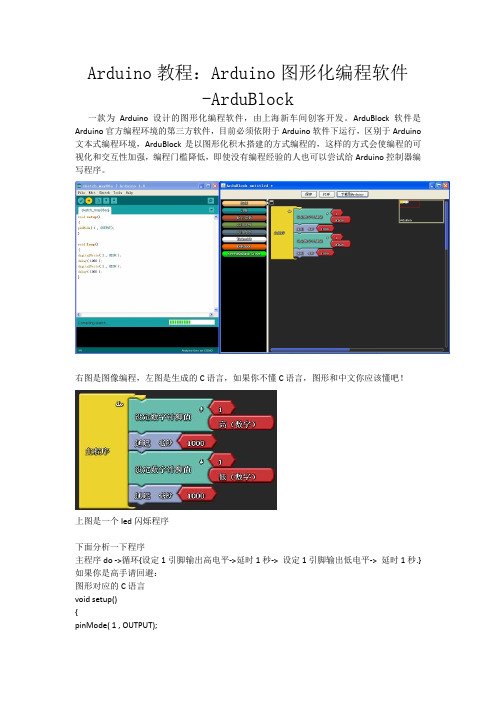
Arduino教程:Arduino图形化编程软件-ArduBlock一款为Arduino设计的图形化编程软件,由上海新车间创客开发。
ArduBlock软件是Arduino官方编程环境的第三方软件,目前必须依附于Arduino软件下运行,区别于Arduino 文本式编程环境,ArduBlock是以图形化积木搭建的方式编程的,这样的方式会使编程的可视化和交互性加强,编程门槛降低,即使没有编程经验的人也可以尝试给Arduino控制器编写程序。
右图是图像编程,左图是生成的C语言,如果你不懂C语言,图形和中文你应该懂吧!上图是一个led闪烁程序下面分析一下程序主程序do ->循环{设定1引脚输出高电平->延时1秒-> 设定1引脚输出低电平-> 延时1秒.}如果你是高手请回避:图形对应的C语言void setup(){pinMode( 1 , OUTPUT);void loop(){digitalWrite( 1 , HIGH );delay( 1000 );digitalWrite( 1 , LOW );delay( 1000 );}兴致来了吧,马上安装。
下载地址:/downloads/taweili/ardublock/ardublock-all.jar 先下载,打开Arduino1.0,点击File,再点击Perferences(如图)我们可以看到弹出的框,记住下面这个路径(如图)D:\我的文档\Arduino\tools\ArduBlockTool\tool进入看看你的文件夹有没有这个路径,如果没有就一直创建文件夹,然后把你下载回来的压缩包(其实是JAVA软件)复制在最后的文件夹里面,就安装完成了。
打开Arduino 1.0开发环境,Tools->ArduBlock这个选项就是(原来没有的)。
arduino基础教程

Arduino基础教程1.LED灯程序:int btnpin=2;int btnpin1=3;int btnpin2=4;int ledpin=10;int ledpin1=12;int ledpin2=11;int btnval;int btn1val;int btn2val;boolean ledstate=false;void setup(){pinMode(btnpin,INPUT_PULLUP); pinMode(btnpin1,INPUT_PULLUP); pinMode(btnpin2,INPUT_PULLUP); pinMode(ledpin,OUTPUT);pinMode(ledpin1,OUTPUT);pinMode(ledpin2,OUTPUT);}void loop(){do{btnval=digitalRead(btnpin);btn1val=digitalRead(btnpin1);btn2val=digitalRead(btnpin2);}while(btnval==HIGH&&btn1val==HIGH&& btn2val==HIGH);if(btnval==LOW&&(!ledstate)){ledstate=true;digitalWrite(ledpin,HIGH);}if(btn1val==LOW&&(!ledstate)){ledstate=true;digitalWrite(ledpin1,HIGH);}if(btn2val==LOW&&(!ledstate)){ledstate=true;digitalWrite(ledpin2,HIGH);}delay(500);}2.数码管显示1-9int A=3;int B=4;int C=6;int D=7;int E=9;int F=10;int G=12;int H=13;void setup(){pinMode(A,OUTPUT); pinMode(B,OUTPUT); pinMode(C,OUTPUT); pinMode(D,OUTPUT); pinMode(E,OUTPUT); pinMode(F,OUTPUT); pinMode(G,OUTPUT); pinMode(H,OUTPUT); }void loop(){zero();delay(1000);one();delay(1000);two();delay(1000);three();delay(1000);four();delay(1000);five();delay(1000);six();delay(1000);seven();delay(1000);eight();delay(1000);nine();delay(1000);}void zero(){digitalWrite(A,LOW); digitalWrite(B,LOW); digitalWrite(C,LOW); digitalWrite(D,LOW); digitalWrite(E,LOW); digitalWrite(F,LOW); digitalWrite(G,HIGH); digitalWrite(H,HIGH); }void one(){digitalWrite(A,HIGH); digitalWrite(B,LOW); digitalWrite(C,LOW); digitalWrite(D,HIGH); digitalWrite(E,HIGH); digitalWrite(F,HIGH); digitalWrite(G,HIGH); digitalWrite(H,HIGH); }void two(){digitalWrite(A,LOW); digitalWrite(B,LOW); digitalWrite(C,HIGH); digitalWrite(D,LOW); digitalWrite(E,LOW); digitalWrite(F,HIGH); digitalWrite(G,LOW); digitalWrite(H,HIGH); }void three(){digitalWrite(A,LOW); digitalWrite(B,LOW); digitalWrite(C,LOW); digitalWrite(D,LOW); digitalWrite(E,HIGH); digitalWrite(F,HIGH); digitalWrite(G,LOW); digitalWrite(H,HIGH); }void four(){digitalWrite(A,HIGH); digitalWrite(B,LOW); digitalWrite(C,LOW); digitalWrite(D,HIGH); digitalWrite(E,HIGH); digitalWrite(F,LOW); digitalWrite(G,LOW); digitalWrite(H,HIGH); }void five(){digitalWrite(A,LOW); digitalWrite(B,HIGH); digitalWrite(C,LOW); digitalWrite(D,LOW); digitalWrite(E,HIGH); digitalWrite(F,LOW); digitalWrite(G,LOW); digitalWrite(H,HIGH); }void six(){digitalWrite(A,LOW); digitalWrite(B,HIGH); digitalWrite(C,LOW); digitalWrite(D,LOW); digitalWrite(E,LOW); digitalWrite(F,LOW);digitalWrite(G,LOW); digitalWrite(H,HIGH); }void seven(){digitalWrite(A,LOW); digitalWrite(B,LOW); digitalWrite(C,LOW); digitalWrite(D,HIGH); digitalWrite(E,HIGH); digitalWrite(F,HIGH); digitalWrite(G,HIGH); digitalWrite(H,HIGH); }void eight(){digitalWrite(A,LOW); digitalWrite(B,LOW); digitalWrite(C,LOW); digitalWrite(D,LOW); digitalWrite(E,LOW); digitalWrite(F,LOW); digitalWrite(G,LOW); digitalWrite(H,HIGH); }void nine(){digitalWrite(A,LOW); digitalWrite(B,LOW); digitalWrite(C,LOW); digitalWrite(D,LOW); digitalWrite(E,HIGH); digitalWrite(F,LOW); digitalWrite(G,LOW); digitalWrite(H,HIGH); }3.LED显示1-4int A=3;int B=4;int C=5;int D=6;int E=7;int F=8;int G=9;int H=10;int com1=11;int com2=12;int com3=13;int com4=2;void setup(){pinMode(A,OUTPUT); pinMode(B,OUTPUT); pinMode(C,OUTPUT); pinMode(D,OUTPUT); pinMode(E,OUTPUT); pinMode(F,OUTPUT); pinMode(G,OUTPUT); pinMode(H,OUTPUT); pinMode(com1,OUTPUT); pinMode(com2,OUTPUT); pinMode(com3,OUTPUT); pinMode(com4,OUTPUT);}void loop(){digitalWrite(com1,HIGH); digitalWrite(com2,LOW); digitalWrite(com3,LOW); digitalWrite(com4,LOW); one();delay(1);digitalWrite(com1,LOW); digitalWrite(com2,HIGH); digitalWrite(com3,LOW); digitalWrite(com4,LOW); two();delay(1);digitalWrite(com1,LOW); digitalWrite(com2,LOW); digitalWrite(com3,HIGH); digitalWrite(com4,LOW); three();delay(1);digitalWrite(com1,LOW); digitalWrite(com2,LOW); digitalWrite(com3,LOW); digitalWrite(com4,HIGH); four();delay(1);}void one(){digitalWrite(A,HIGH); digitalWrite(B,LOW); digitalWrite(C,LOW); digitalWrite(D,HIGH); digitalWrite(E,HIGH); digitalWrite(F,HIGH); digitalWrite(G,HIGH); digitalWrite(H,HIGH);}void two(){digitalWrite(A,LOW); digitalWrite(B,LOW); digitalWrite(C,HIGH); digitalWrite(D,LOW); digitalWrite(E,LOW); digitalWrite(F,HIGH); digitalWrite(G,LOW); digitalWrite(H,HIGH);}void three(){digitalWrite(A,LOW); digitalWrite(B,LOW); digitalWrite(C,LOW); digitalWrite(D,LOW); digitalWrite(E,HIGH); digitalWrite(F,HIGH); digitalWrite(G,LOW); digitalWrite(H,HIGH);}void four(){digitalWrite(A,HIGH); digitalWrite(B,LOW); digitalWrite(C,LOW); digitalWrite(D,HIGH); digitalWrite(E,HIGH); digitalWrite(F,LOW); digitalWrite(G,LOW); digitalWrite(H,HIGH);}4.PWM脉冲宽度调制int serpin=9;int angle;int width;int val;void servopluse(int serpin,int angle){width=(angle*11)+500; digitalWrite(serpin,HIGH); delayMicroseconds(width); digitalWrite(serpin,LOW);delay(20-width/1000);}void setup(){pinMode(serpin,OUTPUT);}void loop() {repeatedly:int i;for(i=0;i<50;i++){servopluse(serpin,180);}}5.步进电机//#include<Stepper.h>//const int stepperint pa=2,pb=3,pc=4,pd=5;void setup(){pinMode(pa,OUTPUT); pinMode(pb,OUTPUT); pinMode(pc,OUTPUT); pinMode(pd,OUTPUT);}void loop(){repeatedly: digitalWrite(pd,HIGH); digitalWrite(pc,LOW); digitalWrite(pb,LOW); digitalWrite(pa,LOW); delay(1); digitalWrite(pd,HIGH); digitalWrite(pc,HIGH); digitalWrite(pb,LOW); digitalWrite(pa,LOW); delay(1); digitalWrite(pd,LOW); digitalWrite(pc,HIGH); digitalWrite(pb,LOW); digitalWrite(pa,LOW);delay(1); digitalWrite(pd,LOW); digitalWrite(pc,HIGH); digitalWrite(pb,HIGH); digitalWrite(pa,LOW); delay(1); digitalWrite(pd,LOW); digitalWrite(pc,LOW); digitalWrite(pb,HIGH); digitalWrite(pa,LOW); delay(1); digitalWrite(pd,LOW); digitalWrite(pc,LOW); digitalWrite(pb,HIGH); digitalWrite(pa,HIGH); delay(1); digitalWrite(pd,LOW); digitalWrite(pc,LOW); digitalWrite(pb,LOW); digitalWrite(pa,HIGH); delay(1); digitalWrite(pd,HIGH ); digitalWrite(pc,LOW); digitalWrite(pb,LOW); digitalWrite(pa,HIGH); delay(1);}6.呼吸灯int ledPin=3;void setup(){// put your setup code here, to run once: }void loop() {for(intfadeValue=0;fadeValue<=255;fadeValue+=5) {analogWrite(ledPin,fadeValue);delay(100);}for(intfadeValue=255;fadeValue>=0;fadeValue-=5) {analogWrite(ledPin,fadeValue);delay(100);}}7.电位器控制LEDint ledPin=3;int pot=A0;int fadeAmount=5;void setup() {}void loop() {for(intfadeValue=0;fadeValue<=255;fadeValue+=5){ analogWrite(ledPin,fadeValue);int time=analogRead(pot)/5;delay(time);}for(intfadeValue=255;fadeValue>=0;fadeValue-=5){ analogWrite(ledPin,fadeValue);delay(analogRead(pot)/5);}} 9串口读取模拟值int pot=A0;void setup(){Serial.begin(9600);}void loop(){int vol=analogRead(pot); Serial.println(vol);}10.光敏电阻(有光不亮无光亮int ledPin=3;int pot=A0;void setup(){Serial.begin(9600);pinMode(ledPin,OUTPUT); }void loop(){int vol=analogRead(pot); Serial.println(vol);if(vol>=990)analogWrite(ledPin,vol); elseanalogWrite(ledPin,0);}10.LM35温度传感器int LM35=A0;void setup(){Serial.begin(9600);}void loop(){floattemp=(5.0*analogRead(LM35)*100.0)/1024; Serial.print("temperature ");Serial.print(temp);Serial.println("C");delay(1000);}11.温度显示。
- 1、下载文档前请自行甄别文档内容的完整性,平台不提供额外的编辑、内容补充、找答案等附加服务。
- 2、"仅部分预览"的文档,不可在线预览部分如存在完整性等问题,可反馈申请退款(可完整预览的文档不适用该条件!)。
- 3、如文档侵犯您的权益,请联系客服反馈,我们会尽快为您处理(人工客服工作时间:9:00-18:30)。
The Pro Mini has 8 analog inputs, each of which provide 10 bits of resolution (i.e. 1024 different values). Four of them are on the headers on the edge of the board; two (inputs 4 and 5) on holes in the interior of the board. The analog inputs measure from ground to VCC. Additionally, some pins have specialized functionality:
Input and Output
Each of the 14 digital pins on the Pro Mini can be used as an input or output, using pinMode() (/en/Reference/PinMode), digitalWrite() (/en/Reference/DigitalWrite), and digitalRead() (/en/Reference/DigitalRead) functions. They operate at 3.3 or 5 volts (depending on the model). Each pin can provide or receive a maximum of 40 mA and has an internal pull-up resistor (disconnected by default) of 20-50 kOhms. In addition, some pins have specialized functions:
ATmega168 3.3V or 5V (depending on model) 3.35 -12 V (3.3V model) or 5 - 12 V (5V model) 14 (of which 6 provide PWM output) 8 40 mA 16 KB (of which 2 KB used by bootloader) 1 KB 512 bytes 8 MHz (3.3V model) or 16 MHz (5V model)
Summary
Microcontroller Operating Voltage Input Voltage Digital I/O Pins Analog Input Pins DC Current per I/O Pin Flash Memory SRAM EEPROM Clock Speed
- Reset. Bring this line LOW to reset the microcontroller. Typically used to add a reset button to shields which block the one on the board.
See also the mapping between Arduino pins and ATmega168 ports (/en/Hacking/PinMapping168).
- RAW. For supplying a raw voltage to the board. - VCC. The regulated 3.3 or 5 volt supply. - GND. Ground pins.
Memory
The ATmega168 has 16 KB of flash memory for storing code (of which 2 KB is used for the bootloader). It has 1 KB of SRAM and 512 bytes of EEPROM (which can be read and written with the EEPROM library (/en/Reference/EEPROM)).
Power
The Arduino Pro Mini can be powered with an FTDI cable or breakout board connected to its six pin header, or with a regulated 3.3V or 5V supply (depending on the model) on the Vcc pin. There is a voltage regulator on board so it can accept voltage up to 12VDC. If you're supplying unregulated power to the board, be sure to connect to the "RAW" pin on not VCC. The power pins are as follows:
Search the Ani
Arduino Pro Mini Front
Arduino Pro Mini Back
(/en/Main/Buy)
Overview
The Arduino Pro Mini is a microcontroller board based on the ATmega168 (datasheet (/dyn/resources/prod_documents/doc2545.pdf)). It has 14 digital input/output pins (of which 6 can be used as PWM outputs), 8 analog inputs, an on-board resonator, a reset button, and holes for mounting pin headers. A six pin header can be connected to an FTDI cable or Sparkfun breakout board to provide USB power and communication to the board. The Arduino Pro Mini is intended for semi-permanent installation in objects or exhibitions. The board comes without pre-mounted headers, allowing the use of various types of connectors or direct soldering of wires. The pin layout is compatible with the Arduino Mini. There are two version of the Pro Mini. One runs at 3.3V and 8 MHz, the other at 5V and 16 MHz. The Arduino Pro Mini was designed and manufactured by SparkFun Electronics.
- I2C: A4 (SDA) and A5 (SCL). Support I2C (TWI) communication using the Wire library (/en/Reference/Wire).
There is another pin on the board:
- Serial: 0 (RX) and 1 (TX). Used to receive (RX) and transmit (TX) TTL serial data. These pins are connected to the TX-0 and RX-1 pins of the six pin header. - External Interrupts: 2 and 3. These pins can be configured to trigger an interrupt on a low value, a rising or falling edge, or a change in value. See the attachInterrupt() (/en/Reference/AttachInterrupt) function for details. - PWM: 3, 5, 6, 9, 10, and 11. Provide 8-bit PWM output with the analogWrite() (/en/Reference/AnalogWrite) function. - SPI: 10 (SS), 11 (MOSI), 12 (MISO), 13 (SCK). These pins support SPI communication, which, although provided by the underlying hardware, is not currently included in the Arduino language. - LED: 13. There is a built-in LED connected to digital pin 13. When the pin is HIGH value, the LED is on, when the pin is LOW, it's off.
Communication
The Arduino Pro Mini has a number of facilities for communicating with a computer, another Arduino, or other microcontrollers. The ATmega168 provides UART TTL serial communication, which is available on digital pins 0 (RX) and 1 (TX). The Arduino software includes a serial monitor which allows simple textual data to be sent to and from the Arduino board via a USB connection. A SoftwareSerial library (/en/Reference/SoftwareSerial) allows for serial communication on any of the Pro Mini's digital pins. The ATmega168 also supports I2C (TWI) and SPI communication. The Arduino software includes a Wire library to simplify use of the I2C bus; see the reference (/en/Reference/Wire) for details. To use the SPI communication, please see the ATmega168 datasheet.