GM8123
基于AT89C51单片机的RS 232串行数据截取器设计
基于AT89C51单片机的RS 232串行数据截取器设计郭付才;王洪涛;刘志华【期刊名称】《现代电子技术》【年(卷),期】2012(35)7【摘要】In order to obtain RS 232 serial communication data, the design based on AT89C51 SCM is introduced. The system used GM8123 chip expanding SCM's one serial port to three serial ports and used MAX232 chip realizing the exchange of RS 232 levels and TTL levels. The serial data was intercepted by SCM's serial port, and then SCM handled those data and sent them to the upper computer. This design has two kinds of work modes. Mode one realized real-time intercepting. Mode two used the store-and-forward principle, the interceptor can work independently.%为了实现对RS 232串行通信数据的截取,给出了基于AT89C51单片机的设计方案.系统利用GM8123芯片将单片机的1个串口扩展成为3个串口,采用MAX232芯片实现RS 232电平与TTL电平之间的相互转换,单片机通过串行口截取通信数据并对数据进行处理,处理后的数据再通过串行口发送到上位机进行显示.该系统具有两种工作模式,模式1实现对通信数据的实时截取,模式2是采用存储转发原理,截取器可以脱离上位机而工作.【总页数】3页(P95-97)【作者】郭付才;王洪涛;刘志华【作者单位】解放军理工大学气象学院,江苏南京211101;解放军理工大学气象学院,江苏南京211101;解放军理工大学气象学院,江苏南京211101【正文语种】中文【中图分类】TN911.7-34【相关文献】1.基于GPRS和HT46RU232单片机的水质监测系统的设计 [J], 贾俊霞;钱游;张建平;2.基于RS232串行数据采集实现串口通信的收发系统 [J], 陆冬妹;邓小芳;罗剑3.基于AT89C51单片机的RS232串行数据截取技术 [J], 刘菲菲;付科研;孙浩;刘蒙;梁孟元;孙锐4.基于PIC18单片机的RS-232/RS-485/CAN互联适配器的设计 [J], 沈毅斌;陈善章;袁明东5.基于STC11FO2E单片机的半双工RS232/RS485转换器设计 [J], 陈凡; 张辉因版权原因,仅展示原文概要,查看原文内容请购买。
GM7123使用说明
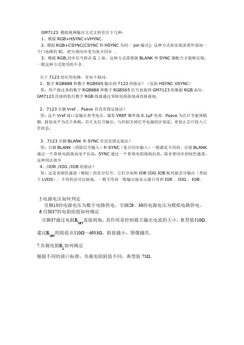
GM7123 模拟视频输出方式支持有以下几种:1、模拟RGB+HSYNC+VHYNC。
2、模拟RGB+CSYNC(CSYNC和HSYNC为同一pin输出),这种方式的实现需要外部加一个门电路的IC,把分离同步变为复合同步。
3、模拟RGB,同步信号附在G上面,这种方式需要跟BLANK和SY NC脚配合才能够实现,一般这种方式使用的不多。
关于7123的应用电路,有如下疑问:1、数字RGB888和数字RGB565输出到7123的接法?(包括HSYNC VSYNC)答:用户接过来的数字RGB888和数字RGB565信号直接到GM7123的数据RGB高位,GM7123没接的低位数字RGB线就通过零欧电阻接地或直接接地。
2、7123引脚Vref 、Psave 有没有固定接法?答:这个Vref端口是输出参考电压,通常VREF脚外接0.1μF电容。
Psave为芯片节能休眠脚,接低电平为芯片休眠,芯片无信号输出,与控制关掉打开电源的区别是,更快让芯片投入工作状态。
3、7123引脚BLANK和SY NC有没有固定接法?答:引脚BLANK(消隐信号输入)和SYNC(复合同步输入)一般都是不用的,分别BLANK 通过一个0欧电阻接高电平拉高,SY NC通过一个0欧电阻接地拉低,除非要同步到绿色通道,这种用法很少4、/IOR /IOG /IOB的接法?答:这是各颜色通道(模拟)的差分信号,它们分别和IOR IOG IOB配对做差分输出(类似于LVDS),不用的话可以接地,一般不用而一般输出接显示器只用到IOR 、IOG 、IOB。
5.电源电压如何判定引脚13的电源电压为数字电路供电,引脚29、30的电源电压为模拟电路供电。
6.引脚37的电阻阻值如何确定连接到地,其作用是控制最大输出电流的大小,典型值510Ω。
引脚37通过电阻RSET建议R的阻值从510Ω~4933Ω,阻值越小,图像越亮。
SET如何确定7.负载电阻RL根据不同的接口标准,负载电阻阻值不同,典型值75Ω。
GC8123完全替代BL8123说明书V1.0

芯片描述GC8123是一款低压5V全桥驱动芯片,为摄像机、消费类产品、玩具和其他低压或者电池供电的运动控制类应用提供了集成的电机驱动解决方案。
GC8123能提供高达1.2A的持续输出电流。
可以工作在1.2~7V的电源电压上。
GC8123具有PWM(IN/IN)输入接口,与行业标准器件兼容,并具有过温保护功能。
芯片应用●摄像机●数字单镜头反光(DSLR)镜头●玩具●机器人技术●共享单车锁●水表开关●医疗设备芯片特点●H桥电机驱动器--电源电压1.2~7V--低导通阻抗(HS+LS)420mΩ● 1.2A持续驱动输出电流●PWM(INA/INB)输入模式●内置过温保护●低电流睡眠模式(nA级,INA=INB=0)产品名封装细节描述GC8123SOT23-6 2.92*1.6,e=1.27管脚分布图管脚描述管脚号管脚名称I/O管脚描述SOT23-61OUTB O输出B2GND gnd地3INA I逻辑输入A4OUTA O输出A5VCC power电源6INB I逻辑输入B内部框图图1GC8123内部框图极限参数(一般无其他特殊注明时,T=25℃)参数符号参数范围单位工作电压VCC-0.3~7V 控制输入电压范围INx-0.5~7V 驱动持续电流Irms 1.2A 驱动峰值电流Imax 2.0A工作温度Top-40~100℃结温Tjmax-40~150℃存储温度Tstg-60~150℃静电保护(人体模式)ESD±4000V电气参数(一般无其他特殊注明时,T=25℃,VCC=5V )推荐工作环境:(无其他说明,T=25℃)电气特性:(无其他说明,T=25℃,VCC=5V )参数符号测试条件最小值典型值最大值单位逻辑电源VCC 1.27V 持续输出电流I OUT 0 1.2A 外部PWM 频率f PWM 0250kHZ 逻辑输入电压V logic 07V 工作温度T a-40100℃参数符号测试条件最小值典型值最大值单位VCC 工作电压VCC 357V VCC 工作电流1I VCC VCC=5V ,无PWM 200550uA VCC 工作电流2I VCCQVCC=5V ,INA=INB=0省电模式0.011uA输出H 桥参数上臂+下臂桥导通电阻R dsON VCC=5V ,I o =400mA;420600mΩ关断态漏电流I OFFV out =0V-200200nA逻辑输入脚(INA,INB)逻辑低输入电压V IL高电平到低电平VCC=3V00.75VVCC=5V 0 1.0逻辑高输入电压V IH低电平到高电平VCC=3V1.3VCC VVCC=5V 2.1VCC输入逻辑迟滞V HY VCC=3V 0.5VVCC=6V0.9逻辑低输入电流I IL V in =0-55uA 逻辑高输入电流I IH V in =3.3V50uA 下拉电阻R pd 100kΩ过温保护电路过温保护TSD 150170180℃过温保护迟滞ΔTSD30℃时序参数与曲线TA=25°C,VCC=5V,RL=20Ω参数条件范围单位最小最大T1启动时间300ns T2关断时间220ns T3输入高到输出高延迟100ns T4输入低到输出低延迟100ns T5输出上升沿10188ns T6输出下降沿10188ns图2GC8123输入输出时间参数1图3GC8123输入输出时间参数2功能描述桥臂控制GC8123由PWM输入接口控制,也被称作IN/IN输入模式,其控制真值表如下:INA INB OUTA OUTB功能00Z Z待机休眠态01L H反向10H L正向11L L刹车输出驱动由于输出驱动管的驱动电压Vgs与电源相关,GC8123的H桥输出导通电阻随电压的升高而变小,所以在低压时,芯片的电流能力会有所下降。
海康威视 HM8123 3 GHz 可编程计数器说明书

T e c h n i c a l D a t aKey facts❙Measurement range: DC to 3GHz Input A/B (BNC): DC to 200MHz Input C (SMA): 100 MHz to 3GHz❙Input impedance A/B: 50Ω or 1MΩ (switchable), sensitivity 25mV Input impedance C: 50Ω, sensitivity 30mV ❙10-digit resolution (at 10s gate time)❙9 measurement functions, external GATE and ARMING connectors (BNC) ❙External Ref.-Input (10MHz) via BNC-connector ❙HM8123: TCXO (temperature stability: ±0.5 x 10⁻⁶) M8123-X: OCXO (temperature stability: ±1.0 x 10⁻⁸) ❙RS-232/USB dual interface, IEEE-488 (GPIB) optional ❙Fanless designP D 5210.8695.32 - 04.00Technical DataHM8123 3 GHz Programmable CounterAll data valid at 23 °C after 30 minutes warm-up.Input characteristics (Input A and B)Connection BNC socketFrequency range0 to 200 MHz DC coupled10 Hz to 200 MHz 1 MΩ, AC coupled500 kHz to 200 MHz50 Ω, AC coupledInput impedance 1 MΩ II 30 pF or 50 Ω (switchable)Attenuation1:1, 1:10, 1:100 (selectable)Sensitivity (normal triggering)0 to 80 MHz25 mV rms (sine wave), 80 mV SS (pulse)80 to 200 MHz65 mV rms (sine wave)20 Hz to 80 MHz50 mV rms (sine wave, auto trigger)Trigger (programmable via encoder or software)Attenuation:Trigger level Resolution1:10 to ±2 V 1 mV1:100 to ±20 V 10 mV1:1000 to ±200 V 100 mVMax. input voltageInput 1 MΩ250 V (DC + ACpeak) from 0 to 440 Hzdecreasing to 8 V rms at 1 MHz Input 50 Ω 5 V rmsMinimum pulse duration<5 ns for single pulseInput noise(typ.) 100 µVAuto trigger (AC coupling)trigger point: 50 % of peak-to-peak value Trigger slope Rising or fallingFilter50 kHz low-pass filter (selectable)Input characteristics (Input C)Connection SMA socketFrequency range:100 MHz to 3 GHzInput sensitivity to 1 GHz: 30 mV rms (typ. 20 mV rms)1 to2 GHz: 100 mV rms (typ. 80 mV rms)2 to 2.5GHz: 150 mV rms (typ. 100 mV rms)2.5 to 3 GHz: 200 mV rms (typ. 150 mV rms)Input impedance50 Ω nominalMax. Input voltage 5 V (DC + AC peak)Input characteristicsExternal Reset Reference Gate/Arming Input impedance 5 kΩ 500 Ω 5 kΩMax. Input voltage±30 V ±20 V ±30 V Input sensitivity- typ. 2 V pp -High level>2 V - >2 V Low level<0,5 V - <0,5 V Min. pulse duration200 ns - 50 ns Input frequency- 10 MHz -Min. eff. gate time- - 20 µs Measurement functionsFrequency A/B/C; period duration A; width A; totalize A; RPM A; frequency ratio A:B; time interval A:B; time interval A:B (average); phase A to B; Duty cycle A; burst measurementsFrequency measurement (Inputs A, B, C)Frequency range0 to 200 MHz (3 GHz)LSD(1,25 x 10⁻⁸ s x frequency) / measurementtime Resolution 1 LSDAccuracy±(resolution/frequency±time inaccuracy±trigger error2) / measurement time) Period duration measurementRange 5 ns to 10,000 sLSD(1.25 x 10⁻⁸ s x period) / measurement time Resolution 1 LSDAccuracy±resolution / period±(trigger error2) / measurement time)T otalization Amanual control external control Range0 to 200 MHz 0 to 200 MHz Min. pulse duration10 ns 10 nsLSD 1 count ±1 count Resolution LSD LSDAccuracy(resolution ±ext. gate time errorx frequency A) / total)Pulse resolution10 ns 10 nsExt. gate error- 100 nsTime interval /Average time interval(Input A = start; Input B = stop)LSD10 ns (0,1 ps to 10 ns im ‘average’ mode) Resolution 1 LSDAccuracy±(resolution + trigger error 2)+system error) / time interval±time base uncertainty(system error: ≤4 ns)Number of average N = 1 to 25 LSD = 10 nsN = 26 to 2,500 LSD = 1 nsN = 2,501 to 250,000 LSD = 100 psN = 250,001 to 25,000,000 LSD = 10 psN = >25,000,000 LSD = 0.1 ps Rpm measurementNPR1) presetting 1 to 65.535 pulses per revolutionGate time330 ms fixedLSD7.5 x 10-8 x revolution speedResolution 1 LSDAccuracy±(trigger error 2) / 0.33)±time base errorOffsetRange Covers the entire measurement range Resolution Same resolution as in normalmeasurement. If the gate time is changedin the offset mode, the offset resolution isthe reference value resolution or the currentreading resolution (whichever is lessprecise).Gate timeRange 1 ms to 65 sResolution 1 msExternal gate time min. 20 µsTime baseFrequency400 MHz clock rate; 10 MHz Quarz Temperature stability(0 to 50 °C)TCXO (standard): ±0,5 x 10⁻⁶OCXO (HO85): ±1,0 x 10⁻⁸Aging TCXO<0.27 ppm per month, 0.05 ppm per day OCXO≤ ±1 x 10⁻⁹/dayExternal Reference10 MHz ±20 ppmMiscellaneousInterface Dual-Interface USB/RS-232 (HO820),optional HO880 IEEE-488 (GPIB)Safety class Safety class I (EN61010-1)Display LCD display (83 x 21 mm)Power Supply115 to 230 V ±10 %, 45 to 60 Hz, CAT II Power consumption approx. 20 WOperating temperature+5 to +40 °CStorage temperature-20 to +70 °CRel. humidity 5 to 80 % (without condensation)Dimensions (W x H x D)285 x 75 x 365 mmWeight approx. 4 kg1) NPR=number of pulses per revolution2) Trigger error= ±noise input (V pp)/slew rate of the input signal Accessories supplied:Line cord, Operating manualRecommended accessories:HO880 Interface IEEE-488 (GPIB), galvanically isolated HZ20 Adapter, BNC to 4mm bananaHZ24 Attenuators 50 Ω (3/6/10/20 dB)HZ42 19“ Rackmount kit 2RUHZ72 GPIB-Cable 2 m。
GM7123介绍

GM7123介绍概述:GM7123 是一个三路高速、数模转换器的单片集成电路。
它包括三路高速、10 位输入的视频DA 转换器、标准的TTL 输入和互补输出高阻抗的模拟输出电流源。
它有三路独立的10 位输入端口,可以在单电源5V下工作,也可以在单电源3.3V 下工作。
GM7123 还有附加的两个视频控制信号:1:复合SYNC(同步信号)2:BLANK (黑电平)GM7123 也有一个待电模式。
GM7123 为48 脚LQFP 封装特点:吞吐量:330 MSPS三通道、10位数模转换器无杂散动态范围(SFDR)RS-343A/RS-170兼容输出互补输出DAC输出电流范围:2 mA至26 mATTL兼容输入1.23 V内部基准电压源3.3 V单电源供电48引脚LQFP封装低功耗:30 mW(最小值,3 V)低功耗(待机模式):6 mW(典型值,3 V)工业级温度范围(-40 ℃到85℃)军品级工作温度(-55℃到125℃)主要应用:数字视频系统(1600x1200@100HZ)高分辨率的彩色图片数字射频调制图像处理仪器视频信号再现。
应用说明主要应用于:数字视频系统(1600×1200@100Hz)、高分辨率彩色图形、数字比例调制、图像处理、使用仪器和视频信号重建等品质功能:功能完全兼容ADV7123,可提供军工品质GM7123。
GM7123 是一款频率330MHz 的 3 通道10 位高速视频DAC芯片,兼容RS-343A/RS-170标准差分输出,输出电流范围是2mA~26mA。
输入兼容TTL 电平,内部基准1.23V,单电源3.3V 供电,采用LQFP48 封装。
该芯片可应用于:数字视频系统(1600×1200@100Hz);高分辨率彩色图像;数字射频调制;图像处理;仪器和视频信号重建等。
2 特征GM7123 自带3 个分离的10 位数据输入端口,有视频控制信号SYNC 和BLANK 分别控制同步和消隐。
高程平差方法 举例说明
高程平差方法举例说明引言在工程建设中不免要对高程控制网进行高精度计算,手工计算对于较为简单的控制网还可适应,但对于较为复杂、节点较多的高程控制网来讲使用手工计算容易出现误差且非常耗时,因此我们针对高程控制网的平差计算原理进行了分析,并利用这一原理结合计算机技术进行了高效的控制网平差计算。
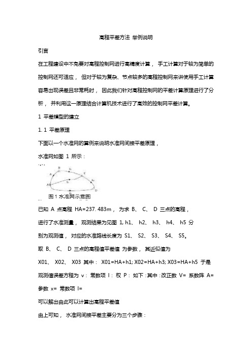
1 平差模型的建立1. 1 平差原理下面以一个水准网的算例来说明水准网间接平差原理,水准网如图1 所示:已知A 点高程HA=237. 483m,为求B、C、D 三点的高程,进行了水准测量,观测结果为见图1, h1、h2、h3、h4、h5 分别为观测值,对应的水准路线长度为S1、S2、S3、S4、S5。
取B、C、D 三点的高程值平差值为参数,其近似值为X01、X02、X03 其中:X01=HA+h1; X02=HA+h3; X03=HA+h5 于是观测值误差方程为v:常数项l:权P:如下:其中:改正数V= 系数阵A= 参数x= 常数项l=可以解出由此可以计算出高程平差值由上可知,水准网间接平差主要分为三个步骤:(1)高程近似值的计算;(2)列立观测值的误差方程;(3)解误差方程并求高程平差值。
1. 2 常数项矩阵的问题在求近似高程时,同一个未知点的近似高程并不是唯一的一个确定值,它的值随着计算时选择的线路不同而改变,因此得出的常数项矩阵L 也并不是唯一的,在下面的程序计算里面,输入已知数据时线路的排序不同,得出的常数项矩阵L 也不同,当然最后得到的高程改正数也不一样,由于进行平差计算时设的未知数就是未知点高程的近似值,因此在最后得到的未知点的高程平差值跟计算高程近似值时选择的线路无关,只要计算正确,最终得到的高程平差值也是正确的。
这一点可以在使用程序的过程中进行检验,无论线路排序如何改变,只要数据输入正确,得到的结果是一样的。
2 平差程序设计2. 1 关于程序语言的选用考虑到本软件所要解决的问题主要是数据的处理与计算,不涉及到计算机系统底层的操作,因此选用相对简单的Visual Basic 6. 0 来进行程序的编写,使用间接平差模型,在保证计算精度的同时,一来减少了代码编写的难度,二来提高了代码执行的效率。
Moxa MGate 5123 产品介绍说明书

MGate5123Series1-port CANopen/J1939-to-PROFINET gatewaysFeatures and Benefits•Simultaneous protocol conversions from CANopen and J1939to PROFINETand SNMP•Supports PROFINET I/O device and SNMP agent•Supports CANopen master and J1939•Flexible deployment with Ethernet cascading and dual subnet•Embedded traffic monitoring/diagnostic information for easy troubleshooting•Easy device configuration via a web-based console•microSD card for configuration backup/duplication•Supports dual redundant DC power inputs and1relay output•CAN port with2-kV isolation protection•-40to75°C wide operating temperature models available•Developed according to IEC62443-4-2with Secure BootCertificationsIntroductionThe MGate5123is an industrial Ethernet gateway for converting CANopen or J1939to PROFINET network communications.To integrate existing CANopen or J1939devices onto a PROFINET network,use the MGate5123as a CANopen or J1939master to collect data and exchange data with the PROFINET IO controller.All models are protected by a rugged and compact metal housing and are DIN-rail mountable.The rugged design is suitable for industrial applications such as factory automation and other process automation industries.Easy ConfigurationThe MGate5123gateways are provided with a web console to make configuration easy without having to install an extra utility.In addition,HTTPS encryption of communication ensures higher network security.In most data-acquisition applications,configuration of CANopen devices can be time-consuming and increase costs.The MGate5123gateways provide EDS file import function and user can auto scan the CANopen devices to help complete the settings quickly.The MGate gateways provide software-configurable termination resistor settings for CANbus to reduce efforts by eliminating the need to open the chassis.Easy TroubleshootingThe MGate5123gateways provide a variety of maintenance functions to reduce troubleshooting time and cost,including LED indicators,protocol diagnostics,traffic monitor,and tag view.These tools help you capture and check data to easily identify the root cause of issues,especially during the installation stage.The MGate gateways also come with status monitoring and fault protection functions.The status monitoring function notifies a PLC/DCS/SCADA system when a CAN device gets disconnected or does not respond,in which case the process PLC/DCS gets the status of each end device and then issues alarms to notify operators.The fault protection function executes actions pre-defined by the user when a host gets disconnected to prevent the end devices from going offline for long periods of time.SpecificationsEthernet Interface10/100BaseT(X)Ports(RJ45connector)2Auto MDI/MDI-X connectionMagnetic Isolation Protection 1.5kV(built-in)Ethernet Software FeaturesIndustrial Protocols PROFINET IO DeviceConfiguration Options Web Console(HTTPS)Device Search Utility(DSU)Management ARPDHCP ClientDNSHTTPHTTPSSMTPSNMP TrapSNMPv1/v2c/v3TCP/IPUDPMIB RFC1213Time Management NTP ClientSecurity FunctionsAuthentication Local databaseEncryption HTTPSAES-128AES-256SHA-256Security Protocols SNMPv3SNMPv2c TrapHTTPS(TLS1.3)CAN InterfaceNo.of Ports1Connector Spring-type Euroblock terminalStandards ISO11898-2Baudrate CANopen:10kbps,20kbps,50kbps,125kbps,250kbps,500kbps,800kbps,1MbpsJ1939:250kbps,500kbps,1MbpsTerminator120ohmssoftware configurableSignals CAN_H,CAN_L,GND,Ext_CAN_H,Ext_CAN_L,CAN_ShieldCAN Software FeaturesIndustrial Protocols CANopen master,J1939CANopenMode MasterMax No.of Nodes64Max No.of Receive PDOs256Max No.of Transmit PDOs256SDOs SupportedInput Data Size2048bytesOutput Data Size2048bytesJ1939Max.No.of Commands256Input Data Size2048bytesOutput Data Size2048bytesPROFINETMode IO Device class BMax.No.of Master Connections2IO controllers(shared devices)Input Data Size1440bytes(bytes per IO Controller,total:2880bytes)Output Data Size1440bytes(bytes per IO Controller,total:2880bytes)MemorymicroSD Slot Up to32GB(SD2.0compatible)Power ParametersInput Voltage12to48VDCInput Current455mA(max)Power Connector Spring-type Euroblock terminalRelaysContact Current Rating Resistive load:2A@30VDCPhysical CharacteristicsHousing MetalIP Rating IP30Dimensions25x90x129.6mm(0.98x3.54x5.1in)Weight294g(0.65lb)Environmental LimitsOperating Temperature MGate5123:-10to60°C(14to140°F)MGate5123-T:-40to75°C(-40to167°F)Storage Temperature(package included)-40to85°C(-40to185°F)Ambient Relative Humidity5to95%(non-condensing)Standards and CertificationsSafety EN61010-2-201UL61010-2-201EMC EN61000-6-2/-6-4EMI FCC Part15B Class AEMS IEC61000-4-2ESD:Contact:8kV;Air:15kVIEC61000-4-3RS:80MHz to1GHz:10V/mIEC61000-4-4EFT:Power:4kV;Signal:2kVIEC61000-4-5Surge:Power:2kV;Signal:2kVIEC61000-4-6CS:150kHz to80MHz:10V/m;Signal:10V/mIEC61000-4-8PFMFFreefall IEC60068-2-31Shock IEC60068-2-27Vibration IEC60068-2-6IEC60068-2-64MTBFTime1,408,984hrs hrsStandards Telcordia SR332WarrantyWarranty Period5yearsDetails See /warrantyPackage ContentsDevice1x MGate5123Series gatewayDocumentation1x quick installation guide1x warranty cardDimensionsOrdering InformationModel Name No.of Serial Ports Operating Temperature MGate51231-10to60°C MGate5123-T1-40to75°C Accessories(sold separately)Wall-Mounting KitsWK-25Wall-mounting kit,2plates,4screws,25x43x2mm©Moxa Inc.All rights reserved.Updated Jun28,2023.This document and any portion thereof may not be reproduced or used in any manner whatsoever without the express written permission of Moxa Inc.Product specifications subject to change without notice.Visit our website for the most up-to-date product information.。
GM7123

PFP80
GM7150C
2
CVBS、Y/C
LQFP32
GM7180C
3
bit CVBS、Y/C、 8-bit ITU-R BT.656 4:2:2 1010-bit LFCSP32 PAL/NTSC 1.8、3.3 LFCSP40 YPbPr YCbCr 86MHz 8/10-bit ITU-R BT.656 4:2:2 YCbCr CVBS、Y/C 12-bit 16/20-bit YCbCr SCART RGB 1.8、3.3 PAL/NTSC LQFP100 140 MHz 24/30-bit YCbCr YPbPr、RGB DDR 8/10-bit 4:2:2 YCbCr DDR 12-bit 4:4:4 RGB
PRODUCT OVERVIEW
—GM7123 视讯产品系列 视讯产品系列—
成都国腾电子技术股份有限公司
器件选型表 1
(Decoder) 视频解码器 视频解码器(
产品型号 输入通 输入信号类 道个数 型 4 CVBS、Y/C 输出数据格式 8-bit ITU-R BT.656 4:2:2 YCbCr 电源 ADC 特 输入视频 封装形式 (V) 性 标准 3.3 9-bit PAL/NTSC 13.5MHz LQFP44
GM7113C
GM7146C
10
CVBS、Y/C 10-bit ITU-R BT.656 4:2:2 11-bit SCART RGB YCbCr 1.8、3.3 PAL/NTSC 30MHz YPbPr 20-bit 4:2:2 YCbCr 9-bit 8-bit ITU-R BT.656 4:2:2 1.8、3.3 PAL/NTSC 27MHz YCbCr
GM7403C
Polyethylene Glycol 6000 产品说明书

81253 Polyethylene glycol 6'000(PEG, Carbowax, Macrogol)CAS number: 25322-68-3Product Description:Molecular formula: H(OCH2CH2)n OH, average value of n = 136.1Average Molecular weight: 6000 (5000-7000) g/molMelting Point: 55 – 60°C (59°C)Solubility: H2O 50 mg/mL at 20°C, complete, colorlesspH: 5.5-7.0 (25°C, 50 mg/mL in H2O)This product is designated as BioUltra for Molecular Biology grade and is suitable for applications in the molecular biology, special if high purity is required. It has been analyzed for low contaminating impurity and the absence of nucleases. Polyethylene glycol (PEG) is a condensation polymer of ethylene oxide and water. PEGs are susceptible to oxidative degradation in the presence of air. Minimizing the exposure of PEG to elevated temperatures and/or exposure to oxygen, or addition of an antioxidant can limit the amount of degradation. PEGs do not hydrolyze or deteriorate upon storage. PEGs do not support the growth of moulds.PEG is incompatible with phenol and may reduce the antimicrobial action of other preservatives. Both penicillin and bacitracin are rapidly inactivated by PEG. PEG is also incompatible with sorbitol, tannic acid and salicylic acid and may affect the integrity of plastics.1Applications:PEG has been used in many different applications. A single-step method is described for the activation of PEG for binding to polypeptides and proteins.2 PEG has been used in the precipitation of proteins.3 PEG is also used as a fusogen to obtain hybridomas for monoclonal antibody production(Induces cell hybridization). 4,5Preparation Instructions:PEG is soluble in water (approximately 630 mg/ml, 20°C). PEGs are also soluble in many polar solvents such as acetone, alcohols and chlorinated solvents. They are insoluble in nonpolar solvents such as hydrocarbons.Storage/Stability:Aqueous PEG solutions are stable at room temperatures. The PEG bonds are not hydrolyzed under these conditions. PEG can be dissolved in warm water at 80-90°C with no adverse effects. Sterile filtration of the solution is recommended using a 0.45 µm filter, initially. Although autoclaving of PEG in saline solutions has been reported6, it is not recommended.The vibrant M and Sigma-Aldrich are trademarks of Merck KGaA, Darmstadt, Germany or its affiliates. Detailed information on trademarks is available via publicly accessible resources. © 2018 Merck KGaA, Darmstadt, Germany and/or its affiliates. All Rights Reserved. References: 1. Martindale The Extra Pharmacopoeia, 30th ed., Reynolds, J. E. F., ed., The Pharmaceutical Press (London, England: 1993), p. 1384. 2. Veronese, F.M., et al., Surface modification of proteins. Activation of monomethoxy-polyethylene glycols by phenylchloroformates and modification of ribonuclease and superoxide dismutase. Appl. Biochem. Biotechnol., 11, 141-152 (1985). 3. Ingham, K.C., Precipitation of Proteins with Polyethylene Glycol. Meth. Enzymol., 182, 301-306 (1990). 4. Harlow, E., and Lane, D., PEG used as a fusogen to obtain hybridomas for monoclonal antibody production, ed., Antibodies: A Laboratory Manual , Cold Spring Harbor, NY (1998), 211-213 5. Davidson, R.L., and Gerald, P.S., Induction of mammalian somatic cell hybridization by polyethylene glycol Meth. Cell Biol. 15, 325-338 (1977) 6. de St.Groth, S.F., and Scheidegger, D., Production of monoclonal antibodies: strategy and tactics. J. Immunol. Methods, 35, 1-21 (1980). Precautions and Disclaimer: This product is for R&D use only, not for drug, household, or other uses. Please consult the Material Safety Data Sheet for information regarding hazards and safe handling practices.。
智能家居元件清单
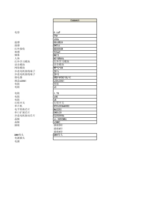
Designator
C1, C4, C5, C6, C7, C8, C9, C10, C12, C14, C15, C16, C17, C20 C2, C3, C18, C19 C11, C13 J2 J3 J4 J5 J6 J7 J8 J9 U3 J12 J13 JD-1, JD-2 LCD R1 R3, R8 R4, R5, R6, R10, R11, R13 R7 R9, R12 S2, S3 U1 U2 U4 U5 Y1 Y2
J1 J10
Footprint
LibRef
CAP CAP CAP-P Header 3 Header 4 Header 3 Header 4 Header 4 Header 3 Header 4 Header 5 ST_MW_08S Header 3 Header 3 继电器 LCD-12864 排阻 RES2
4.7K 10K 1K 行程开关 STC12C5A60S2 MAX232 GM8123 ULN2003A 11.0592MHz 12MHZ 插座3针 插座3针 插座4针 DB9母头
瓷片电容 瓷片电容 电解电容
Description
全方位下载型红外遥控学习模块
KF301-3P 接线端子 脚距5.08MM 三位 KF301-3P 接线端子 脚距5.08MM 三位 SRD-5VDC-SL-C
电容
温感 湿感 红外接收 雨感 烟雾 人体 红外学习模块 语音模块 网络模块 步进电机接线端子 步进电机接线端子 继电器 液晶12864 电阻 电阻
电阻 电阻 电阻 行程开关 单片机 电平转换芯片 串口扩展芯片 步进电机驱动芯片 晶振 晶振 插座
DB9母头 电源插头 电源
பைடு நூலகம்
GM8126_GM8128介绍
GM8126_GM8128介绍首先介绍GM8126处理器。
它采用了四核Cortex-A7架构,最高主频可达1.2GHz。
由于采用了较新的Cortex-A7架构,GM8126在性能上有了较大提升。
同时,它还集成了ARM Mali-400MP2 GPU,提供了良好的图形处理能力,能够满足大部分应用的需求。
此外,GM8126还集成了高性能的视频和音频编解码器,支持多种格式的视频和音频播放。
GM8126采用了低功耗设计,功耗控制得到了进一步优化。
此外,它还可以通过设计延长系统的工作时间。
这使得GM8126非常适合一些对续航能力要求较高的应用,比如便携式设备、智能家居和物联网应用等。
GM8126还支持H.265和H.264的硬件解码,可以在减少功耗的同时提供高画质的视频。
其次介绍GM8128处理器。
它也采用了四核Cortex-A7架构,最高主频可达1.3GHz。
GM8128相比于GM8126,在性能上有一定提升。
它同样集成了ARM Mali-400MP2 GPU和高性能的视频和音频编解码器,能够支持复杂的图形和多媒体应用。
GM8128同样采用了低功耗设计,并且具备较高的能效比。
它可以满足高性能应用中的功耗和热管理的需求,同时保持较长的续航时间。
GM8128支持多种接口和外设,如USB、HDMI、SPI、I2C、UART等。
这使得GM8128可以很方便地与其他硬件设备进行连接和通信,提高设备的应用灵活性。
GM8126和GM8128均采用了28纳米工艺制造,这使得它们的成本大幅降低,从而提供了更好的性价比。
这也使得它们非常适合用于智能移动终端、视频监控、智能家居、工业自动化和物联网等领域。
它们不仅仅在高性能上取得突破,同时也能满足低功耗、低成本和高集成度的需求。
综上所述,GM8126和GM8128是瑞芯微推出的高性能应用处理器。
它们采用了四核Cortex-A7架构,有着较高的性能、低功耗和低成本等优势。
它们适用于智能移动终端、视频监控、智能家居、工业自动化和物联网等多个领域。
GM8123在智能电动柜通信系统中的应用

4基 于 GM8 2 . 1 3的 串 口 扩展 41 .GM8 2 介 13简
G 8 2 可 以将一个全双工的标准 串口扩展成 3 M 13 个标准 串口, 并能 通过外部 引脚控制串 口扩展模式 : 单通道工作模式和多通道工作模式。 42G 13芯片工作模 式 . M8 2 () 1单通道工作模式 当模式控 制引脚 MS:1时 , 片工作在单通 道工作模式下 , 芯 单通 道模式在~个时刻只允许一组 R D和 T D与母 串 口进行 通讯 ,子串 X X 口最高波特率支持 2 Mb s 0 p。外部 MC U通过两根输 入地址线 和两根输 出地址线选择指定和母 串口连接的子 串口。 表 1G 13工作模式 M8 2
[ 关键词 ] M82 P 9 6 9 电动柜 G 13 8 C 6
1引 言 .
扩展。
智能电动推柜系统具有可视化人机操作 界面 ,它 的人性化表现为 具有可视化人机操作界面 , 特点就是通信控制板 能分别与 P C机 、 触摸 屏和备用设备独立地进行信息交换。主板 的核 心控制器采用具有 2个 增强型 U T的 P 9 6 9芯 片 , AR 8C6 既要构造 R 4 5总线 , S8 又要与 PC、 触 摸屏等设 备通信 , 串口显 然不够用 。通 过比较 ,在设计 中采用 了 2个 G 1 3通用 异步串口 l扩 3芯 片)将 P 9 6 9的 U R 0扩展成 3个 M8 2 ( , 8C6 AT 独立的 U R 分别 与 P 、 A T, C 触摸 屏及备用设备通信 , 从而实 现在 触摸显 示屏 或 P c等设备上直接控制智能电动推柜进行安全有效地移动 。 2电 动推 柜 系统 组 成 与功 能 . 智能电动推柜系统主要由触摸显示屏 、 通信控制板( 以下简称主板 ) 、 若干分散控 制板( 以下简称控制板 ) 及各种传感 器和执行机构等组成 。 主板通过 R 45 S 8 总线与安装 于各个柜子上的控制顿通信协 调各个柜子
成都国腾微电子 通用异步串口扩展芯片GM812X 说明书

成都国腾微电子有限公司GM812X 通用异步串口扩展芯片 应用手册 2004.2 GM812X 版本记录:1.0 当前版本时间:2004年2月 新旧版本改动比较: 旧版 文档页数 当前版本 文档页数 主题(和旧版本相比的主要变化) 如果您有技术、交付或价格方面的任何问题,请联系成都国腾微电子有限公司的相关办公室或当地的代理商,或访问我们的网站:www.gticc.com ,谢谢! 编制时间:2004年2月 由成都国腾微电子有限公司发布 发布地点:成都 成都国腾微电子有限公司版权所有。
1 概述GM812X系列串口扩展芯片可为用户提供最简单和高性能的通用串口扩展方案,该系列芯片子串口最高波特率达38400bps。
该芯片提供两种工作模式,用户可根据需要灵活选择。
该芯片母串口和子串口的工作波特率可由软件调节,而不需要修改外部电路和晶振频率。
GM812X系列芯片的外部控制少,应用灵活,编程使用简单,适合于大多数需要多串口扩展的应用场合。
2 应用说明2.1 硬件接口GM812X系列的典型应用如图1所示:图1 典型硬件接口电路图1中选用89C51作为系统的主机,通过GM8125扩展了5个子串口,5个子串口可以与5个从机相接。
如果用户只需要扩展3个串口,则可采用GM8123,硬件连接方法和GM8125相同。
2.2 程序示例2.2.1 单通道工作模式程序示例此程序应用的环境是5个从机分别以1200、2400、4800、9600、19200bps的波特率工作,并且主机与5个从机的数据通讯采用分时的方式,即每次只对一个从机发送和接收数据。
程序以C51为例:/**************************************************************//*CPU:AT89C51 *//*晶体频率:22.1184MHz *//*机器周期:0.54uS *//*语言:C51 *//**************************************************************/#include <reg51.h>#define DELAY_TIME 60000 //Delay time/**********************I/O定义***********************/sbit MS=P3^6; //GM8125工作模式控制sbit RESET=P3^7; //GM8125复位引脚控制/******************数据变量定义*****************/unsigned char SendBuff[5]={0xaa,0x45,0x67,0xbc,0xc9};unsigned char ReceiveBuff[5]={0x00,0x00,0x00,0x00,0x00};unsigned char i=0 ,j=0 ,k=1,c=0;/*********************************************//*函数名称:delay.C *//*函数功能:延时程序 *//*********************************************/void delay(unsigned int m){unsigned int n;n=0;while(n < m){n++;}return;}/******************************************************//*函数名称: MAIN.C *//*函数功能:主机主程序 *//*********************************************/void main(void){TMOD = 0x20; //指定定时器1工作在方式2IE = 0x90; //开串行口中断SCON=0xc0; //串行口工作在方式3for(c=0;c<5;c++) //选择5个子串口以5种不同波特率工作{switch(c){case 0:{TH1=0xd0; //装入定时器1初值,设置工作波特率为1200bps TL1=0xd0;PCON=0x00;P1=0x11; //选择8125子通道1工作break;}case 1:{TH1 = 0xe8; //装入定时器1初值,设置工作波特率为2400bpsTL1 = 0xe8;PCON=0x00;P1=0x22; //选择8125子通道2工作break;}case 2:{TH1 = 0xf4; //装入定时器1初值,设置工作波特率为4800bpsTL1 = 0xf4;PCON=0x00;P1=0x33; //选择8125子通道3工作break;}case 3:{TH1 = 0xfa; //装入定时器1初值,设置工作波特率为9600bpsTL1 = 0xfa;PCON=0x00;P1=0x44; //选择8125子通道4工作break;}case 4:{TH1 = 0xfd; //装入定时器1初值,设置工作波特率为19200bpsTL1 = 0xfd;PCON=0x00;P1=0x55; //选择8125子通道5工作break;}default:break;}TR1=1; //启动定时器1MS=1; //GM8125工作在单通道工作模式下/*主控MCU发送/接收程序*/SBUF=SendBuff[i];while(TI==0);TI=0;i++;REN = 1;while(j!= k); //等待接收完成REN = 0; //停止接收k++;TR1=0; //T1停止}}void CommReceive(void) interrupt 4{if(RI){ReceiveBuff[j] = SBUF;RI = 0;j++;}}2.2.2 多通道工作模式程序示例此程序应用的环境是5个从机均以19200bps的波特率工作,要求主机对5个从机分别发送完数据后要等待从机向主机返回一个数据。
无人机大气数据高速检测系统的设计

Abstract How to advance the test speed of air data(UAV)is an important item in improvement of flight
control s)rstem per formance. It’S difi cult to increase the data acquisition speed from data acquisition entrance when the sensor module has been chosen.A design method of data test system based on GM 8123 is provided, which applies serial port expansion technologies to real ize data transfer, acquisition and processing with high speed . rhis scheme is proved to be valuable in improvement of dynamic perform ance and testing precision for UAV test system .
基于GM8123的串口扩展硬件解决方案

1
在某 些 特定 的情 况下 。 片机 应 用 系 统需 要 连 单 故选择 C1= 5n 。 9 1 F
321 ..1电容性 模式 检测 电容
;
个 单 片 机应 用 系统 通 过 串 行接 E 连 接 到 一 台 主 控 l
基 于智 能控制 器 IB FD G的荧光 灯 电子镇 流 C 1L 1
摘 要 :目前 。 于 串行接 口的扩展 解 决 方案 包括 : 用软件 虚 拟 串口和硬 件 接 口器件 扩 展 两 种 方 基 使
案 。前者 因为存 在 着较 为严 重 的误 码 概 率 , 能增加 系统 的使 用风 险。后 者 虽增加 了硬件 开销 , 可 却 可 以有 效降 低 系统 的误 码风 险 。 最新 的 G 1X扩 展 方案 在 不 明显增 加硬 件 开销 的 前提 下 , M8 2 可有 效 解 决通 信过程 中的误 码 问题 , 降低 系统 的软 件 风 险 , 高 系统 的 可 靠性 。通过 典 型应 用 实例 , 提 给
参考 文献 :
2V则 有 : ,
C1 = 9 8 C1 =A
=
△ B L 8
1 F 2V4 0V 7 F 5n x /1 = 3p 故 选择 C 86 F 1= 8p 。
321 2及 L 1与 L 2的选择 ..2 L 2 2
(1 1)
[】 兴 武 , 大 卫. 1 毛 祝 电子镇 流 器原 理与 制作[ . 京 : M】 北
器使 用 少 量 的元 件 , 即可 获 得 高 功 率 因数 、 预 热 灯
若I C引脚 1 ( E ) 的 A 电平 范 围 △ E 2R S 上 C R S
=
启 动 , 具 有 高安 全 性 和 可靠 性 。IB1L 1 并 C F 0 G不 仅
AC Current Probe Model JM813 用户手册说明书

®AC Current Probe Model JM813User ManualDESCRIPTIONThe JM813 (Catalog #2110.93) is designed for use in industrial environments. The “squared” jaws permit multiple conductor or bus bar positioning. The current output makes it the perfect tool for measurement with DMMs, recorders, power and harmonic meters. The Model JM813 is compatible with any AC ammeter, multimeter, or other current measuring instrument with an input impedance lower than 0.6 . To achieve the stated accuracy, use the JM813 with the DMM having an accuracy of 0.75%.WARNINGThese safety warnings are provided to ensure the safety of personnel and proper operation of the instrument.• Read the instruction manual completely and follow all the safety information before attempting to use or service this instrument. • Use caution on any circuit: Potentially high voltages and currents may be present and may pose a shock hazard. • Read the Safety Specifications section prior to using the current probe. Never exceed themaximum voltage ratings given. • Safety is the responsibility of the operator.• ALWAYS connect the current probe to the display device before clamping the probe onto the sample being tested. • ALWAYS inspect the instrument, probe, probe cable, and output terminals prior to use. Replace any defective parts immediately. • NEVER use the current probe on electrical conductors rated above 600 V in overvoltage category III (CAT III). Use extreme caution when clamping around bare conductors or bus bars. INTERNATIONAL ELECTRICAL SYMBOLSThis symbol signifies that the current probe is protected by double or reinforced insulation. Use only factory specified replacement parts when servicing the instrument.This symbol signifies CAUTION! and requests that the user refer to the user manual before using the instrument.This is a type A current sensor. This symbol signifies that application around and removal from HAZARDOUS LIVE conductors is permitted.DEFINITION OF MEASUREMENT CATEGORIESCat. II: For measurements performed on circuits directly connected to the electrical distribution system.Examples are measurements on household appliances or portable tools. Cat. III: For measurements performed in the building installation at the distribution level such as onhardwired equipment in fixed installation and circuit breakers.Cat. IV: For measurements performed at the primary electrical supply (<1000V) such as on primaryovercurrent protection devices, ripple control units, or meters. RECEIVING YOUR SHIPMENTUpon receiving your shipment, make sure that the contents are consistent with the packing list. Notify your distributor of any missing items. If the equipment appears to be damaged, file a claim immediately with the carrier and notify your distributor at once, giving a detailed description of any damage.ELECTRICAL SPECIFICATIONS Current Range:1 to 2400A AC, continuous cycle forthe full temperature range(3000A if ambient temperature < 35°C or 95°F) Transformation Ratio:3000:3Output Signal:1mA AC/A AC (3A at 3000A) Accuracy and Phase Shift*:Primary current 150A 600A 3000A Accuracy % 1.5% 0.75% 0.5% Phase shift 1.5° 0.75° 0.5°(*Reference conditions: 23°C ±3°K, 20 to 85% RH, 48 to 65Hz, external magnetic field < 40 A/m, no DC component, no external current carrying conductor, test sample centered.)Load impedance 0.55Ω.Overload: 3600A during 5 mn Accuracy: Per IEC 185-26-27Class 0.5 from 48 to 1000HzAmpere Second Product: 90 A.s Frequency Range:30 Hz to 5 kHz; current derating above1 kHz for continuous useLoad Impedance: ≤ 0.6ΩWorking Voltage: 600V ACCommon Mode Voltage: 600V AC Influence of Adjacent Conductor:0.005A/A ACInfluence of Conductor in Jaw Opening: 1% ± 0.1A of readingMECHANICAL SPECIFICATIONS Operating Temperature:14° to 122°F (-10° to 50°C)Storage Temperature:-13° to 176°F (-25° to 80°C)Influence of Temperature:< 0.1% per 10°KJaw Opening: 3.54" (90 mm)Maximum Conductor Size:Cable: 2.52" max. (64mm)Bus bar: 1.97 x 5.31" (50 x 135 mm)2.52 x3.94" (64 x 100 mm) Envelope Protection: IP 20 (IEC 529) Drop Test:500mm (IEC 68-2-32)Mechanical Shock:100g (IEC 68-2-27)Vibration:10/55/10Hz, 0.15mm (IEC 68-2-6) Polycarbonate Material:Handles:10% fiberglass chargedpolycarbonate UL 94 V0Jaws: ABS UL 94 V2Dimensions:4.72 x 12.40 x 1.89" (120 x 315 x 48 mm) Weight:2.65 lbs. (1200 g)Colors:Dark gray handles with red jawsOutput:Two standard safety banana jacks (4mm) SAFETY SPECIFICATIONSElectrical:Double insulation or reinforced insulation between primary or secondary and outer case of handle upon IEC 1010-2-32Common Mode Voltage:600V Category III, Pollution: 2ORDERING INFORMATIONCurrent Probe JM813 ...................... C at #2110.93 Accessories:Leads, set of 2, 5 ft safety (1000V) ... C at #2111.29 Lead No. 211 for Probe 5A Series(5 ft. rated 250V) ............................... C at #2950.06OPERATIONPlease make sure that you have already read and fully understand the WARNING section on page 1. Making Measurements with the AC Current Probe Model JM813.∙Connect the black and red terminals to the Ampere AC range of your DMM or current measuring instrument. Select the appropriate current range (5A AC). Clamp the probe around the conductor to be tested. If the reading is less than 2A, select the lower range until you obtain the best resolution. Read the value display on the DMM and multiply it by the probe ratio (1000/1). (If reading = 0.592A AC, the current flowing through the probe is 0.592A x 1000 = 592A AC).∙For best accuracy: carefully center the conductor inside the probe jaw, avoid if possible, the proximity of other conductors which may create noise.Tips for Making Precise Measurements∙When using a current probe with a meter, it is important to select the range that provides the best resolution. Failure to do this may result in measurement errors.∙Make sure that probe jaw mating surfaces are free of dust and contamination. Contaminants cause air gaps between the jaws, increasing the phase shift between primary and secondary. It is very critical for power measurement.MAINTENANCE:Warning∙For maintenance use only original factory replacement parts.∙To avoid electrical shock, do not attempt to perform any servicing unless you are qualified to do so.∙To avoid electrical shock and/or damage to the instrument, do not get water or other foreign agents into the probe.MaintenanceTo ensure optimum performance, it is important to keep the probe jaw mating surfaces clean at all times. Failure to do so may result in error in readings. The following is the recommended procedure for cleaning the probe jaws; Use a very fine sand paper (fine 600) to avoid scratching the jaw, then gently clean with a soft oiled cloth.REPAIR AND CALIBRATIONYou must contact our Service Center for a Customer Service Authorization number (CSA#). This will ensure that when your instrument arrives, it will be tracked and processed promptly. Please write the CSA# on the outside of the shipping container.Chauvin Arnoux®, Inc. d.b.a. AEMC® Instruments15 Faraday Drive ∙ Dover, NH 03820 USA(800)945-2362(Ext.360)•(603)749-6434(Ext.360)•***************(Or contact your authorized distributor)NOTE: All customers must obtain a CSA# before returning any instrument.TECHNICAL AND SALES ASSISTANCEIf you are experiencing any technical problems, or require any assistance with the proper use or application of this instrument, please contact our technical hotline:(800)343-1391•(508)698-2115•********************LIMITED WARRANTYThe current probe is warranted to the owner for a period of two years from the date of original purchase against defects in manufacture. This limited warranty is given by AEMC® Instruments, not by the distributor from whom it was purchased. This warranty is void if the unit has been tampered with, abused or if the defect is related to service not performed by AEMC® Instruments.Full warranty coverage and product registration is available on our website at:/warranty.html.Please print the online Warranty Coverage Information for your records.99-MAN 100115 - v8 04/17。
GM8283C_数据手册,RGB转LVDS,TTL转LVDS
PLLVCC
PLL 电源端
7
TXIN9
数据输入端
35
PLLGND
PLL 地端
8
TXIN10
数据输入端
36
LVDSGND
LVDS 地端
9
VCC
TX 数字电源端
37
TXOUT3+
数据输出端
10
TXIN11
数据输入端
38
TXOUT3-
数据输出端
11
TXIN12
数据输入端
39
TXCLKOUT+
时钟输出端
12
ns
1.88 3.56
5.24 6.92 8.60
香港众鑫微电子有限公司
金R 15013505758 Q10862894
4
28 位可编程数据选通发送器
数据 BIT6 输出与时钟输 出的相对时间 时钟延迟时间
锁相环建立时间 关断延迟时间 输入时钟抖动
6 机械尺寸
td6
9.88
tCDD
TA=25℃,VCC=3.3V
香港众鑫微电子有限公司
金R 15013505758 Q10862894
6
28 位可编程数据选通发送器
数据手册
GM8283C
对于输入时钟与数据的关系,要求如下: 建立时间:tSU≥2.5ns,保持时间:tH≥0ns。 2)输出的 4 路串行数据流与同步时钟对应时序关系如下图 5 所示:
TXCLKOUT
0.35tCIP
0.50tCIP
0.65tCIP
tXIT
输入数据转换时间
1.0
3.0
6.0
tSTC
建立时间
2.5
Vxworks下PCI总线驱动程序设计

Vxworks下PCI总线驱动程序设计作者:黄辽宁来源:《电脑知识与技术》2012年第29期摘要:该文阐述了在vxworks系统下,pci总线驱动程序的编写方法,并且给出了详细的源代码。
关键词:PCI; vxworks;驱动程序;运动控制卡中图分类号:TP311 文献标识码:A 文章编号:1009-3044(2012)29-6966-03VxWorks是目前世界上用户数量最大的实时嵌入式操作系统, 它具有高度可剪裁的微内核结构、高效的多任务调度、灵活的任务间通信手段、快速灵活的I/O系统、确定的微妙级中断延迟时间等优点。
本文介绍了基于PCI 接口规范的通用运动控制卡在VxWorks下的驱动程序的设计。
对其设计驱动程序需要对实时操作系统、实时软件设计、硬件设备有深入的了解。
因此, 该设计不仅本身具有很高的应用价值, 也为实时驱动程序的设计提供了一个样例。
1 系统组成在基于微机的数据采集、处理与控制系统中,计算机接口卡常常是其中的关键硬件设备。
目前在运动控制领域,各类运动控制卡得到广泛运用,其中以工控机通过ISA或PCI等系统总线连接运动控制卡的主从式结构最为流行,由工控机发出控制指令和参数,控制卡根据接收到的指令及参数完成具体控制功能。
由于PCI总线的高速和即插即用特性,使其取代ISA被广泛应用于高速数据采集与传输等系统中,有效地解决了实时采集、实时传输和实时存储等问题。
2 PCI 配置空间PCI系统具有三种地址空间:存储器空间、I/O空间和配置空间。
每个PCI设备都有64个配置双字用于实现配置寄存器,64个配置双字分为两部分,⑴PCI协议定义了开头16个双字的格式和用途,称为设备的配置头区域;⑵其它48个双字的用途是由设备指定的。
目前PCI 协议定义了两种头区域格式,第1类配置头区域用于定义PCI-PCI桥,而第0类配置头区域用于定义其它PCI设备。
所有的PCI设备,包括PCI-PCI桥都必须实现下述配置寄存器:厂商标志、设备标志、命令、状态、分类码、版本标志和头区域类型寄存器。
嵌入式系统中扩展串行口的几种方法

为 000 时写命令字 引脚 MS 为 1 SP2338 唤醒 但由于 SP2338 的唤
STADD2 ̄STADD0 为 000 时读命令 醒时间需要 25ms 左右 故用于芯片
字 进行工作方式设置时 芯片的 唤醒的数据将不会被主机接收 因
帧格式和母串口工作波特率与上一 此 可以先发送一个字节数据用于
134 2006.7 电子设计应用
万方数据
嵌入式系统
讯 并且通讯过程完全由主机控制 的帧格式为11bit 母串口波特率为
的系统 多通道模式下 各子串口 7200bps
波特率相同 允许所有子串口同时
基于 SP2338 的串行口扩展
与母串口通讯 母串口以子串口波
S P 2 3 3 8 是采用低功耗 C M O S
参考文献 1. 刘毓梅等 通过异步串口扩 展芯片 GM8123/25 的原理和应用 成都国腾微电子公司 2004 2.李华艾编 Mcs-5系列单片机 实用接口技术 北京航空航天大学 出版社 2001
136
133 发出一个中断 调用中断例 程 利用掉电保护电路所维持的工 作时间保存当前打印位置 系统停 止工作 待重新上电后检测到 打 印未完成 标志 则读出最后一张 发票明细数据 从断电时记录的位 置继续打印出一张完整的发票 并 清除标志
相似文献(10条)
数据安全性处理 税控收款机集商务 税控 管 理等功能于一体 对数据的传输和 存储要求相当高 需要能够正确地 传输 存储 生成及反馈数据 因 此 对安全性的要求也相当高 本 系统的安全性设计从以下几个方面 来体现 系统中采取了用户权限分级管
理的方法 设置了三种具有不同操 作权限的角色 系统管理员 收款 员 税务稽查员 用户与角色关联 用户密码采用 6 位  ̄8 位数字 密码 以密文形式存储在Flash内 进入相 应的用户模式都要通过对应的密码 校验 才能够登录税控收款机 执 行本用户级的相应操作
- 1、下载文档前请自行甄别文档内容的完整性,平台不提供额外的编辑、内容补充、找答案等附加服务。
- 2、"仅部分预览"的文档,不可在线预览部分如存在完整性等问题,可反馈申请退款(可完整预览的文档不适用该条件!)。
- 3、如文档侵犯您的权益,请联系客服反馈,我们会尽快为您处理(人工客服工作时间:9:00-18:30)。
数据手册
第 6 页 共 13 页
2006 年 6 月
成都国腾微电子有限公司
GM8123
图 6 子口接收母口发送时序图 注:Tda:一帧数据发送结束,对应子口地址保持最小时间
4.3 外部复位功能
外部 MCU 可以通过向 RST 引脚产生一个低电平使该芯片复位,复位信号在外部电平拉高
Ttb:MS 有效到输入数据有效的最小时间 Ttd:数据从一口接收到另一口发送的最大延迟时间
4.2 多通道工作模式
当模式控制引脚 MS = 0 时,芯片工作在多通道工作模式下,多通道模式允许 3 个子串口同
时全双工地工作。在该工作模式下,芯片的地址线 STADD1~0 是输入口,由 MCU 控制选择希
后内部还将延时 200ms,复位后芯片内部所有 BUFFER 和寄存器内的数据都将被清零。复位后
芯片命令字寄存器的默认状态参见表 5;
表 5 命令字寄存器的默认状态
参数名
默认状态
BR2~0
000(1200bps)
FL
1(11bit 一帧)
注:该芯片不具备上电复位功能,用户在使用前必须通过复位引脚对芯片进行复位。
图 4 母口(RXD0)接收时序图 注: Tad:地址有效到母口接收数据的起始位的最小时间
Tar:地址的最少保持时间
图 5 只向一个子串口连续发数据时序图
4.2.2 子口接收母口发送流程详述
GM8123 子串口可主动响应从机的发送要求,只要芯片工作在多通道模式下,子串口不需 要控制就可以主动接收从机送来的数据,同时由母串口发送给主机,并将 SRADD1~0 置成该子 串口地址,主机接收到这帧数据后,可通过对 SRADD1~0 的检测判断该数据来自哪一个子串口, 从而对这帧数据进行相应处理。芯片内部采用对各子串口顺序检测的方式,即先检测子串口 1, 再检测子串口 2,直到子串口 3,先检测的子串口有数据则先发送,无数据就检测下一子串口。
旧版 文档页数
当前版本 文档页数
主题(和旧版本相比的主要变化)
11
14
增加封装机械尺寸、取消 DIP24 封装
14
14
修改读命令字操作的工作方式
14
14
修改输入高电平 VIH 的最小值
14
13
取消 SSOP 封装
如果您有技术、交付或价格方面的任何问题,请联系成都国腾微电子有限公司的相关办公室或当地的代理
电源地;带‘*’的 GND 引脚由于内部设计原因要求必须接地
TXD0
Out 母通道的发送端口;
RXD0
In
母通道的接收端口;
RST
In
系统复位
SRADD1 In/Out 接收子通道地址 1;
SRADD0 In/Out 接收子通道地址 0;
STADD1
In
发送子通道地址 1;
STADD0
In
发送子通道地址 0;
NC 8 VDD 9 TXD2 10 RXD2 11 GND 12
GM8123-I
GM8123
24 VDD 23 MS 22 STADD0 21 STADD1 20 NC 19 SRADD0 18 SRADD1 17 VDD 16 RST 15 RXD0 14 TXD0 13 GND*
OSCI 1 OSCO 2 TXD1 3 RXD1 4 TXD3 5 RXD3 6
3 封装及引脚功能说明
GM8123 提供多电源和单电源两种封装,并提供 DIP、SDIP、SOP、SSOP 等多种封装形式, 用户可根据各自系统的应用环境选择不同等级的封装,引脚排布见图 1 Байду номын сангаас示:
数据手册
第 2 页 共 13 页
2006 年 6 月
成都国腾微电子有限公司
GND 1 OSCI 2 OSCO 3 TXD1 4 RXD1 5 TXD3 6 RXD3 7
NC 7 TXD2 8 RXD2 9
GND 10
GM8123-S
20 VDD 19 MS 18 STADD0 17 STADD1 16 SRADD0 15 SRADD1 14 RST 13 RXD0 12 TXD0 11 GND*
图 1 封装引脚排布图
该芯片的各引脚功能描述见表 1:
表 1 芯片引脚功能说明
GM8123
1 概述
GM8123 可以将一个全双工的标准串口扩展成 3 个标准串口,并能通过外部引脚控制串口 扩展模式:单通道工作模式和多通道工作模式,即可以指定一个子串口和母串口以相同的波特 率单一的工作,也可以让所有子串口在母串口波特率基础上分频同时工作。
该芯片工作在多通道模式下时,子串口能主动响应从机发送的数据,并由母串口发送给主 机,同时返回子串口地址。该模式使每个从机的发送要求都能被及时地响应,即使所有从机同 时有发送要求,数据也不会丢失,基本实现了主控单元和外设通讯的实时性。
1
0
选择子串口 2 的 TXD
1
1
选择子串口 3 的 TXD
其时序如图 2 和 3 所示:
数据手册
图 2 帧长为 10bits 时的时序图
第 4 页 共 13 页
2006 年 6 月
成都国腾微电子有限公司
GM8123
图 3 帧长为 11bits 时的时序图 注:Tta:地址(SRADD/STADD)有效到输入数据有效的最小时间
4.4 芯片的工作方式设置
芯片的工作方式设置包括串口帧格式设置和通讯波特率设置。芯片进行工作方式设置时, MS 为‘0’、STADD1~0 为‘00’时写命令字,MS 为‘1’、STADD1~0 全为 0 时读命令字。此 时芯片的帧格式和母串口工作波特率与上一次进行数据通讯时一致,比如上一次通讯采用 10bit 一帧的格式,母串口波特率为 9600bps,则写/读命令字也采用同样的帧格式和波特率(注意: 复位后的帧格式为 11bit,母串口波特率为 4800bps)。完成命令字的设置之后,必须将 STADD1~0 置为非全 0 的值后,设置才生效,此时才能按设置的格式进行数据通讯。
注意:由于母口波特率是子口波特率的 4 倍,母口发送 4 帧的时间子口才能发送一帧,所 以若只需要对一个子口进行连续发送,则必须对母口发送进行延时操作,延时可采用延时程序 实现,也可通过对母串口发送无效数据来实现,具体方法为将地址线 STADD 置为全 0,然后对 母串口写 0x00。例如只需要对子串口 2 连续写两帧数据,则先向子串口 2 发送一帧数据,然后 将地址线置为 0,MCU 发送 3 个 0x00,然后再向子串口 2 发送第二帧数据,若不进行延时操作 或发送延时数据不为 0x00 将导致不可预料的结果。只向一个子串口连续发数据的时序如图 5 所 示。如果需要向所有子串口发送,则不需要延时操作,只需要依次向各个子串口发送即可。
成都国腾微电子有限公司
GM8123
1 扩 3 的通用异步串口扩展芯片
数据手册 2006.6
成都国腾微电子有限公司
GM8123
GM8123
版本记录:2.3 当前版本时间:2006 年 6 月
新旧版本改动比较:
接收到母串口送来的数据后就可根据 SRADD1~0 状态判断数据是从哪一个子串口送来 的;发送时先由 MCU 选择子串口再向母串口发送数据 ——与标准串口通讯格式兼容,TTL 电平输出 ——宽工作电压:2.3~6.7V ——输出波特率误差小于 0.2%,输入波特率误差要求小于 2.8% ——每 bit 采样 16 次,提高数据正确性 ——输入地址引脚有 50~80KΩ Pull-Down 电阻,其它输入引脚有 50~80KΩ Pull-Up 电 阻(OSCI 除外)
望发送数据的子串口,地址线 SRADD1~0 是输出口,用于向 MCU 返回接收到数据的子串口地
址。
各地址线定义如表 3 和表 4 所示:
表 3 多通道工作模式下子串口发送地址线定义
STADD1 STADD0
定义
0
1
选择子串口 1 发送
1
0
选择子串口 2 发送
1
1
选择子串口 3 发送
表 4 多通道工作模式下子串口接收地址线状态
进行工作方式设置时可将写入的命令字通过 TXD0 返回给 MCU,以保证初始化可靠,即进 行读命令字操作。读命令字时地址线 SRADD 将向 MCU 返回命令字寄存器地址‘00’,此方式 和多通道模式下子串口接收数据相同,MCU 可根据地址区别接收到的数据是子口数据还是命 令字。
当模式控制引脚 MS = 1 时,芯片工作在单通道工作模式下,单通道模式在一个时刻只允许
一组 RXD 和 TXD 与母串口进行通讯。芯片的地址线用于选择希望和母串口相连接的子串口,
外部 MCU 通过两根输入地址线和两根输出地址线选择指定和母串口连接的子串口。输入/输出
地址线可以不相同,则连接到母串口上的 RXD 和 TXD 可以属于不同的子串口。
该芯片母串口和子串口的工作波特率可由软件调节,而不需要修改外部电路和晶振频率。 该芯片的外部控制少,应用灵活,编程使用简单,适用于大多数有串口扩展需求的系统。
2 特征
——采用写控制字的方式对芯片进行控制 ——各子串口波特率可调(统一调节) ——数据格式 10 位或 11 位可选 ——单通道模式下,最高波特率支持 20Mbps;多通道模式下,子串口最高波特率 38400bps ——子串口数:3 个 ——由一个引脚选择芯片的工作方式是单通道工作模式还是多通道工作模式 ——在单通道工作模式下,芯片工作无需初始化设置,工作串口由地址线控制选择 ——在多通道工作模式下,各子串口的波特率等于母串口波特率的 4 分频 ——在多通道工作模式下,接收时地址线 SRADD1~0 向 MCU 返回接收子通道的地址,MCU
