自动喷水灭火系统的计算书
自动喷淋系统计算
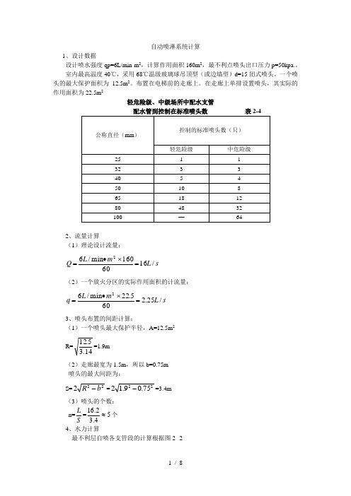
自动喷淋系统计算1、设计数据设计喷水强度qp=6L/min·m 2,计算作用面积160m 2,最不利点喷头出口压力p=50kpa.。
室内最高温度40℃,采用68℃温级玻璃球吊顶型(或边墙型)d=15闭式喷头。
一个喷头的最大保护面积为12.5m 2。
布置在电梯前的走廊上。
在走廊上单排设置喷头,其实际的作用面积为22.5m 2轻危险级、中级场所中配水支管2、流量计算(1)理论设计流量:s L m L Q /1660160min /62=⨯•=(2)一个放火分区的实际作用面积的计流量:s L m L q /25.2605.22min /62=⨯•=3、喷头布置的间距计算:(1)一个喷头最大保护半径,A=12.5m 2 R=14.35.12=1.9m (2)走廊最宽为1.5m ,所以b=0.75m 喷头的最大间距为:S=222b R -=2275.09.12-=3.4m (3)喷头的个数: n=S L =54.32.16≈个 4、水力计算最不利层自喷各支管段的计算根据图2--21最不利层喷头计算图图2—2(1)各支管段的流量计算:①a 处的喷头出水量;/94.050133.0S L H k q a a === a-b 管采用DN=25mm ,A=0.4367h a-b =210b a ALq -=294.04.34367.010⨯⨯⨯=13.1KpaHb=Ha+ha-b=50+13.1=63.1Kpa②b 处的喷头出水量;/06.11.63133.0S L H k q b b === q b-c =q a +q b =0.94+1.06=2.00L/S b-c 管采用DN=32mm ,A=0.09386h b-c =210c b ALq -=200.24.309386.010⨯⨯⨯=12.76Kpa H c = H b +H b-c =63.1+12.76=75.86Kpa③c 处的喷头出水量;/16.186.75133.0S L H k q c c ===④其它喷头都以上面一样算,为了计算简便以表格的形式。
喷淋计算书

自动灭火喷淋系统水力计算书水力计算自动喷水灭火系统的水力计算主要是按照逐点计算法进行计算;这于原规范有很大区别。
原规范是采用估算法进行计算的.计算方法:1、确定喷头间距规范中给出了如下面所示的间距。
这个间距是最大间距,也就是在0.1Mpa下的间距。
喷水强度(L/min·m2)正方形布置的边长(m)矩形或平行四边形布置的长边边长(m)一只喷头的最大保护面积(m2)喷头与端墙的最大距离(m)4 4.4 4.520.02。
263。
6 4.012。
5 1.88 3.4 3.611.5 1.712~20 3.0 3.69.0 1.5注:1 仅在走道设置单排喷头的闭式系统,其喷头间距应按走道地面不留漏喷空白点确定;2 货架内喷头的间距不应小于2m,并不应大于3m。
很多设计者对这一点不是很了解,往往不论建筑物的实际尺寸,都一律套用这个距离,造成很多错误.对于一个建筑物,我们在确定了危险等级后,要根据建筑物的实际尺寸来确定喷头间距,如我们确定了一个建筑物为中危险Ⅱ级,也既喷水强度为8 L/min·m2由下图可知由上述图纸可以明白系统最不利点四个喷头ABCD围成的面积正方形ABCD的面积为S,只要保证S内的喷水强度不小于8 L/min·m2就满足规范要求;从图上看,在每个喷头的洒水量中有1/4的水量洒在S中,也就是S内的洒水量为一个喷头的洒水量;由喷头的流量公式喷头的流量应按下式计算:(9.1.l)式中q——喷头流量(L/min);P——喷头工作压力(MPa);K——喷头流量系数.可知q/S=8 L/min·m2;而S=L*L则,喷头间距L=当最不利点压力P=0.1Mpa时,L=3。
16m=3.1m;当最不利点压力为0。
05Mpa时,L=2.66m=2.6m 也就是说,在中危险Ⅱ级,也既喷水强度为8 L/min·m2时,喷头间距在2。
6m~3。
1m之间布置。
我们实际布置时,考虑喷头间距与建筑物尺寸的和谐,距离端墙保证不大于间距的一半.比如上图,我们保证喷头间距的均匀相等后,假如间距为3。
水喷雾灭火系统水力计算书【范本模板】

xx大厦直燃机房水喷雾灭火系统设计说明1、确定保护对象的设计喷雾强度:燃气直燃机房保护目的为冷却,设计喷雾强度为9L/min。
m2,持续喷雾强度为1小时。
2、计算保护面积S:根据《喷雾规范》第3.1.5条,保护面积应按保护对象外表面积确定.直燃机其外形尺寸为:L=3。
5米、B=1.9米、H=2。
0m。
S=(1。
9+3。
5)*2*2+3。
5*1.9=28.25m23、计算水雾喷头的流量q:要计算水雾喷头的流量q,首先要确定水雾喷头型号.为了节约投资应选雾化角较大的喷头,其在相同的水压下保护面积较大。
水雾喷头选用ZSTWB-16-120型水雾喷头,该喷射器雾化角120度,流量适中,K=16。
q=K·(10·P)0。
5,P=0.35 MPa (《喷雾规范》要求)q=16*(10*0.35)0.5≈30L/ min(1)计算所需水雾喷头的最小数量N:N=s·W /q=28。
25*9/30≈9个4、喷头布置合理地布置水雾喷头,可以使喷雾均匀地完全覆盖保护对象,确保喷雾强度。
《喷雾规范》第3.2.3条规定“水雾喷头与保护对象之间的距离不得大于水雾喷头的有效射程。
”第3.2.4条规定“水雾喷头的平面布置方式可为矩形或菱形。
当按矩形布置时,水雾喷头之间的距离不应大于1。
4倍水雾喷头的水雾锥底圆半径;当按菱形布置时,水雾喷头之间的距离不应大于1.7倍水雾喷头的水雾锥底圆半径。
"故应根据喷头有效射程、水雾锥度圆半径来布置喷头,也就是说水雾要直接喷射到保护对象并完全覆盖。
本设计按矩形布置喷头,为了达到直接喷射的目的,一台直燃机设置了14个喷头。
喷头布置后,经校核喷头间距、水雾覆盖情况,完全满足规范要求.水雾锥底圆半径R为1。
21m(B:0.7、θ:120°)。
喷头间距应小于1.4R=1。
4*1。
21=1.7m由平面及系统图可知喷头间距全部小于1.70米。
5、水泵流量Q=1.1*30L/min*14*2=14.4L/S参考文献:1.《水喷雾灭火系统设计规范》2.《建筑给水排水设计手册》3.《建筑设计防火规范》。
自动喷水灭火系统的计算书
自动喷水灭火系统的计算书1. 自动喷水灭火水力计算的基本数据1.1喷头的选择 《自动喷洒灭火系统设计规范》,闭式湿式自动喷水灭火系统适用范围:因管网及喷头中充水,故适用于环境温度为4~700C 之间的建筑物内,所以选用闭式湿式喷头。
1.2根据湿式系统、预作用系统不宜超过800只;本系统设四个湿式报警阀,每个报阀组控制的最不利喷头处,都设末端试水装置,每层最不利喷头处均设直径为25mm 的试水阀。
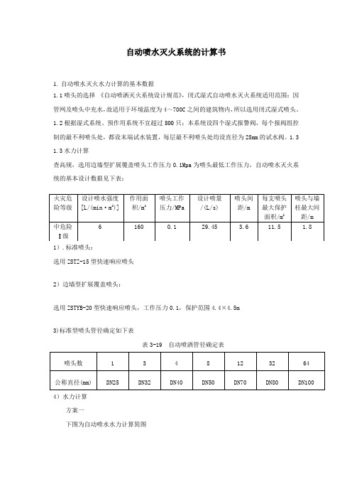
1.3 1.3水力计算查高规,选用边墙型扩展覆盖喷头工作压力0.1Mpa 为喷头最低工作压力,自动喷水灭火系统的基本设计数据见下表: 1).标准喷头:选用ZSTZ-15型快速响应喷头2)边墙型扩展覆盖喷头:选用ZSTYB-20型快速响应喷头,工作压力0.1,保护范围4.4×4.5m3)标准型喷头管径确定如下表表3-19 自动喷洒管径确定表喷头数 1 3 4 8 12 32 64 公称直径(mm) DN25DN32DN40DN50DN70DN80DN1004)水力计算方案一下图为自动喷水水力计算简图火灾危险等级 设计喷水强度[L/(min ·m 2)] 作用面 积/m 2喷头工作压力/MPa 设计喷量/(L/s) 喷头间 距/m 每支喷头最大保护面积/m 2 喷头与墙柱最大间距/m 中危险Ⅰ级61600.129.453.611.51.8下表为自动喷水水力计算表管段名称起点压力mH2O管道流量L/s管长m当量长度管径mmK 水力坡降mH2O/m流速m/s损失mH2O终点压力mH2O1-2 10.00 1.91 1.32 0.60 25 115 1.591 3.60 3.05 13.05 2-3 13.05 1.91 1.18 0.80 25 80 1.591 3.60 3.14 16.20 21-22 11.09 2.01 0.94 0.60 25 115 1.765 3.79 2.71 13.81 22-3 13.81 2.01 0.54 0.80 25 80 1.765 3.79 2.36 16.17 3-4 16.20 3.92 1.40 2.10 32 80 1.441 4.13 5.05 21.24 23-4 18.59 1.81 1.22 0.60 25 80 1.431 3.41 2.60 21.20 24-4 19.84 1.87 0.34 0.60 25 80 1.527 3.52 1.44 21.29 4-5 21.24 7.60 1.94 3.10 50 80 0.640 3.58 3.23 24.47 25-26 16.88 1.73 2.25 0.80 25 80 1.299 3.25 3.96 20.84 26-5 20.84 3.64 0.75 2.10 32 80 1.244 3.84 3.54 24.38 27-5 19.53 1.86 2.65 0.60 25 80 1.503 3.50 4.89 24.42 5-6 24.47 13.10 0.43 3.10 50 80 1.901 6.17 6.71 31.18 6-7 31.18 13.10 1.22 0.00 50 80 1.901 6.17 2.31 33.49 7-8 33.49 13.10 2.72 2.10 50 80 1.901 6.17 9.16 42.65 8-9 42.65 13.10 4.23 0.00 80 80 0.200 2.64 0.85 43.50 28-29 14.66 2.31 1.32 0.60 25 115 2.332 4.35 4.48 19.14 29-30 19.14 2.31 0.93 0.80 25 80 2.332 4.35 4.03 23.17 33-34 15.47 2.37 0.94 0.60 25 115 2.460 4.47 3.78 19.25 34-30 19.25 2.37 0.78 0.80 25 80 2.460 4.47 3.90 23.1530-31 23.17 4.69 1.38 2.10 32 80 2.060 4.94 7.18 30.34 35-31 26.72 2.17 1.17 0.60 25 80 2.057 4.09 3.63 30.35 36-31 28.13 2.23 0.39 0.60 25 80 2.165 4.20 2.15 30.27 31-32 30.34 9.08 1.94 3.10 50 80 0.914 4.28 4.61 34.95 37-32 29.06 2.26 2.01 0.60 25 80 2.237 4.26 5.83 34.89 38-32 30.31 2.31 1.39 0.60 25 80 2.333 4.36 4.65 34.96 32-9 34.95 13.66 0.44 3.70 50 80 2.067 6.43 8.55 43.50 9-10 43.50 26.76 5.62 5.40 80 80 0.836 5.39 9.21 52.71 10-11 52.71 26.76 1.84 0.00 100 80 0.191 3.09 0.35 53.06 39-11 40.00 2.66 1.76 1.40 32 80 0.662 2.80 2.09 42.09 11-12 53.06 29.42 2.65 6.10 100 80 0.231 3.40 2.02 55.09 12-13 55.09 29.42 1.83 1.10 100 80 0.231 3.40 0.68 55.77 13-14 55.77 29.42 0.47 0.00 125 80 0.075 2.22 0.03 55.80 14-15 55.80 29.42 0.02 3.70 125 80 0.075 2.22 0.28 56.08 15-16 56.08 29.42 3.06 0.00 125 80 0.075 2.22 0.23 56.31 16-17 56.31 29.42 2.95 3.70 125 80 0.075 2.22 0.50 56.80 17-18 56.80 29.42 0.63 0.00 125 80 0.075 2.22 0.05 56.85 18-19 56.85 29.42 4.70 3.70 125 80 0.075 2.22 0.63 57.47 19-20 57.47 29.42 0.69 0.00 125 80 0.075 2.22 0.05 57.53计算结果:所选作用面积:160.0平方米总流量:29.42 L/s平均喷水强度:11.03 L/min.平方米入口压力:57.53 米水柱水泵扬程为:H=Hr+Hz+报警阀损失+1.1×∑h=7.43+61+5+2+57.57= 133.米水柱Hr 入口压力Hz 水泵吸入口至入口静水压(按本工程确定层高计算为61m)∑h水泵吸入口至入口沿程及局部水头损失(管道长度+当量长度=195m,按干管管径选用DN150计算)7.43米水柱报警阀水头损失取0.04Mpa,水流指示器取0.02Mpa,方案二下图为自动喷水水力计算简图下表为自动喷水水力计算表管段名称起点压力mH2O管道流量L/s管长m当量长度管径mmK 水力坡降mH2O/m流速m/s损失mH2O终点压力mH2O1-2 10.00 1.91 1.32 0.90 32 115 0.342 2.01 0.76 10.76 2-3 10.76 1.91 1.18 1.20 32 80 0.342 2.01 0.81 11.57 21-22 10.31 1.94 0.94 0.90 32 115 0.353 2.04 0.65 10.96 22-3 10.96 1.94 0.54 1.20 32 80 0.353 2.04 0.61 11.57 3-4 11.57 3.85 1.40 2.70 40 80 0.659 3.06 2.70 14.27 23-4 12.50 1.48 1.22 0.60 25 80 0.962 2.80 1.75 14.25 24-4 13.28 1.53 0.34 0.60 25 80 1.022 2.88 0.96 14.25 4-5 14.27 6.86 1.94 3.10 50 80 0.522 3.23 2.63 16.90 25-26 11.72 1.44 2.25 0.80 25 80 0.902 2.71 2.75 14.47 26-5 14.47 3.04 0.75 2.10 32 80 0.864 3.20 2.46 16.93 27-5 13.59 1.55 2.65 0.60 25 80 1.046 2.92 3.40 17.00 5-6 16.90 11.45 0.43 3.10 50 80 1.451 5.39 5.13 22.03 6-7 22.03 11.45 1.22 0.00 50 80 1.451 5.39 1.76 23.79 7-8 23.79 11.45 2.72 2.10 50 80 1.451 5.39 6.99 30.78 8-9 30.78 11.45 4.23 0.00 80 80 0.153 2.31 0.65 31.43 28-29 14.72 2.32 1.32 0.90 32 115 0.503 2.44 1.12 15.8329-30 15.83 2.32 0.93 1.20 32 80 0.503 2.44 1.07 16.90 33-34 15.00 2.34 0.94 0.90 32 115 0.513 2.47 0.94 15.94 34-30 15.94 2.34 0.78 1.20 32 80 0.513 2.47 1.02 16.96 30-31 16.90 4.65 1.38 2.70 40 80 0.964 3.70 3.94 20.84 35-31 18.28 1.80 1.17 0.60 25 80 1.407 3.38 2.49 20.77 36-31 19.38 1.85 0.39 0.60 25 80 1.491 3.48 1.48 20.86 31-32 20.84 8.30 1.94 3.10 50 80 0.763 3.91 3.85 24.68 37-32 20.63 1.91 2.01 0.60 25 80 1.588 3.59 4.14 24.76 38-32 21.41 1.94 1.39 0.60 25 80 1.648 3.66 3.28 24.69 32-9 24.68 12.15 0.44 3.70 50 80 1.635 5.72 6.76 31.45 9-10 31.43 23.60 5.62 5.40 80 80 0.650 4.75 7.16 38.60 10-11 38.60 23.60 1.84 0.00 100 80 0.149 2.73 0.27 38.87 39-11 36.88 2.55 1.76 1.40 32 80 0.610 2.69 1.93 38.80 11-12 38.87 26.15 2.65 6.10 100 80 0.183 3.02 1.60 40.47 12-13 40.47 26.15 1.83 1.10 100 80 0.183 3.02 0.53 41.00 13-14 41.00 26.15 0.47 0.00 125 80 0.059 1.97 0.03 41.03 14-15 41.03 26.15 0.02 3.70 125 80 0.059 1.97 0.22 41.25 15-16 41.25 26.15 3.06 0.00 125 80 0.059 1.97 0.18 41.43 16-17 41.43 26.15 2.95 3.70 125 80 0.059 1.97 0.39 41.82 17-18 41.82 26.15 0.63 0.00 125 80 0.059 1.97 0.04 41.86 18-19 41.86 26.15 4.70 5.00 125 80 0.059 1.97 0.57 42.43 19-20 42.43 26.15 0.69 0.00 150 80 0.023 1.39 0.02 42.45计算结果:所选作用面积:160.0平方米总流量:26.15 L/s平均喷水强度:9.81 L/min.平方米入口压力:42.45 米水柱水泵扬程为:H=Hr+Hz+报警阀损失+1.1×∑h=7.43+61+5+2+42.45=117.88米水柱Hr 入口压力Hz 水泵吸入口至入口静水压(按本工程确定层高计算为61m)∑h水泵吸入口至入口沿程及局部水头损失(管道长度+当量长度=195m,按干管管径选用DN150计算)7.43米水柱报警阀水头损失取0.04Mpa,水流指示器取0.02Mpa,比较两方案因方案一,所计算水泵扬程超出原喷淋泵扬程,故选用方案二所确定的喷淋管径。
自动喷水系统计算书

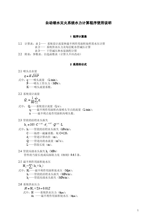
自动喷水系统设计计算书业主:XX精密工业(苏州)有限公司专案名称:AUO-VIP Project设计计算书:自动喷水系统一、计算过程中所用公式喷头的流量计算:q=K√10P式中q——喷头流量(L/min);P——喷头工作压力(MPa);K——喷头流量系数。
系统的设计流量:Q s=∑qi式中Q s——系统设计流量(L/s);qi——最不利点处作用面积内各喷头节点的流量(L/min)n——最不利点处作用面积内喷头数.管道的水头损失:h=iL=0.0000107×V2L/d j1.3式中h——配管摩擦水头损失(MPa);i——每米管道的水头损失(Mpa/m);V——管道内水的平均流速(m/s);d j——管道的计算内径(m)取值按管道的内径减1mm确定;L——配管直管长与各接头,阀类换算而得的当量直管长之和(m)二、作用面积的确定作用面积:200m2喷水强度:18L/min. m2喷头流量系数:K=115最不利点处喷头的工作压力:P0=0.16Mpa每个喷头的保护面积:3.0×2.65=7.95 m2保护面积内的喷头数:n=200/7.95=25.15=26只正方形面积的长边尺寸:L=√200=14.14m每根喷水支管的动作喷头数:n=6只三、消防管道的局部水头损失见附件一四、自动喷水系统立体图见附件二五、逐点计算1、q a= K√10P0=115×√10×0.16=2.424L/s32A的计算内径是:d j=0.031m异径接头50A/32A的当量长度:0.45mV A-B=4×2.424/1000×3.14×0.0312=3.214m/sH A-B=i A-B L A-B=0.0000107×V A-B2×L A-B/ d j1.3=0.0000107×3.214×3.214×3.45/0.0311.3=0.035Mpa P B=0.16+0.035=0.195Mpa2、q B= K√10P B=115×√10×0.195=2.676L/s50A的计算内径是:d j=0.052mq B=2.424+2.676=5.1L/sV B-C=4×5.1/1000×3.14×0.0522=2.403m/sH B-C=i B-C L B-C=0.0000107×V B-C2×L B-C/ d j1.3=0.0000107×2.403×2.403×3/0.0521.3=0.009Mpa P C=0.195+0.009=0.204Mpa3、q C’=K√10P c=115×√10×0.204=2.738 L/s50A的计算内径是:d j=0.052m异径接头80A/50A的当量长度:0.75mq C=5.1+2.738=7.838L/sV C-D=4×7.838/1000×3.14×0.0522=3.693m/sH C-D=i C-D L C-D=0.0000107×V C-D2×L C-D/ d j1.3=0.0000107×3.693×3.693×3.75/0.0521.3=0.026Mpa P D=0.204+0.026=0.23Mpa4、q D’=K√10P D=115×√10×0.23=2.907 L/s80A的计算内径是:d j=0.081mq D=7.838+2.907=10.745L/sV D-E=4×10.745/1000×3.14×0.0812=2.086m/sH D-E=i D-E L D-E=0.0000107×V D-E2×L D-E/ d j1.3=0.0000107×2.086×2.086×3/0.0811.3=0.004Mpa P E=0.23+0.004=0.234Mpa5、q E’=K√10P E=115×√10×0.234=2.932 L/s80A的计算内径是:d j=0.081mq E=10.745+2.932=13.677L/sV E-F=4×13.677/1000×3.14×0.0812=2.656m/sH E-F=i E-F L E-F=0.0000107×V E-F2×L E-F/ d j1.3=0.0000107×2.656×2.656×3/0.0811.3=0.006Mpa P F=0.234+0.006=0.24Mpa6、q F’=K√10P F=115×√10×0.24=2.969 L/s80A的计算内径是:d j=0.081m异径接头200A/80A的当量长度:1.6mq F=13.677+2.969=16.646L/sV F-G=4×16.646/1000×3.14×0.0812=3.232m/sH F-G=i F-G L F-G=0.0000107×V F-G2×L F-G/ d j1.3=0.0000107×3.232×3.232×3.1/0.0811.3=0.009Mpa P G=0.24+0.009=0.249Mpa7、对于节点G,其流量和所需的工作压力为:q G=16.646L/sP G=0.249Mpa用管道特性系数B K1表示配水支管1的输水性能:令B K1= q G2/ P G=16.646×16.646/0.249=1112.81200A的计算内径是d j=0.207m三通200A/80A的当量长度为:12.3mV G-H=4×16.646/1000×3.14×0.2072=0.495m/sH G-H=i G-H L G-H=0.0000107×V G-H2×L G-H/ d j1.3=0.0000107×0.495×0.495×14.95/0.2071.3= 0.0004Mpa P H=0.249+0.0004=0.2494Mpa配水支管2的流量:q H’=√B K1P H=√1112.81×0.2494=16.66L/s8、q H= q G+ q H’ =16.646+16.66=33.306L/s200A的计算内径是d j=0.207m三通200A/80A的当量长度为:12.3mV H-I=4×33.306/1000×3.14×0.2072=0.990m/sH H-I=i H-I L H-I=0.0000107×V H-I2×L H-I/ d j1.3=0.0000107×0.990×0.990×14.95/0.2071.3= 0.0012Mpa P I=0.2494+0.0012=0.2506Mpa配水支管3的流量:q I’=√B K1P I=√1112.81×0.2506=16.699L/s9、q I= q H+ q I’ =33.306+16.699=50.005L/s200A的计算内径是d j=0.207m三通200A/80A的当量长度为:12.3mV I-J=4×50.005/1000×3.14×0.2072=1.487m/sH I-J=i I-J L I-J=0.0000107×V I-J2×L I-J/ d j1.3=0.0000107×1.487×1.487×14.95/0.2071.3= 0.0028Mpa P J=0.2506+0.0028=0.2534Mpa配水支管4的流量:q J’=√B K1P J=√1112.81×0.2534=16.792L/s10、q J= q I+ q J’ =50.005+16.792=66.797L/s200A的计算内径是d j=0.207m三通200A/80A的当量长度为:12.3mV J-K=4×66.797/1000×3.14×0.2072=1.986m/sH J-K=i J-K L J-K=0.0000107×V J-K2×L J-K/ d j1.3=0.0000107×1.986×1.986×14.95/0.2071.3= 0.0049Mpa P K=0.2534+0.0049=0.2583Mpa11、设Ka处的工作压力为P Ka,则q Ka=K√10P Ka则80A的计算内径是d j=0.081mV Ka-Kb=4×115×√10P la/1000×3.14×0.0812×60=0.372×√10P KaH Ka-Kb=i Ka-Kb L Ka-Kb=0.0000107×V Ka-Kb2×L Ka-Kb/ d j1.3=0.0000107×0.372√10P la×0.372×√10P Ka×3/0.0811.3= 0.0011 P KaP Kb= P Ka+H Ka-Kb=1.0011 P Ka12、q Kb’=K√10P Kb=115×√10×1.0011 P Ka =6.064√P Kaq Kb= q Ka+ q Kb’ =6.061√P Ka+6.064√P Ka=12.125√P Ka80A的计算内径是d j=0.081m异径接头200A/80A的当量长度:1.6mV Kb-K=4×12.125√P la/1000×3.14×0.0812×=2.354√P laH Kb-K=i Kb-K L Kb-K=0.0000107×V Kb-K2×L Kb-K/ d j1.3=0.0000107×2.354√P Ka×2.354√P Ka×3.1/0.0811.3= 0.0048 P KaP K= P Kb+H Kb-K=1.0059 P KaP K=0.2583Mpa故P Ka=0.2568Mpa所以q Ka=K√10P Ka=115×√10×0.2568=3.071L/sq Kb=12.125√P Ka=6.144L/s13、系统的设计流量:Q S=∑qi=66.797+6.144=72.941L/s200A的计算内径为d j=0.207m200A的90度弯头的当量长度是6.2m200A的蝶阀的当量长度是5.2m200A的闸阀的当量长度是1.3m200A的止回阀的当量长度是17.0mV K-L=4×72.941/1000×3.14×0.207×0.207=2.169m/sH K-L=i K-L L K-L=0.0000107×V K-L2×L K-L/ d j1.3=0.0000107×2.169×2.169×188.9/0.2071.3=0.0737Mpa250A的计算内径为d j=0.250m250A的90度弯头的当量长度是7.6m250A的蝶阀的当量长度是6.3m250A的闸阀的当量长度是1.6m250A的止回阀的当量长度是21.1mV L-M=4×72.941/1000×3.14×0.250×0.250=1.487m/sH L-M=i L-M L L-M=0.0000107×V L-M2×L L-M/ d j1.3=0.0000107×1.487×1.487×270/0.2501.3=0.0387Mpa六、自动配水泵配管摩擦损失水头计算H A-B+ H B-C+ H C-D+ H D-E+ H E-F+ H F-G+ H G-H+ H H-I+ H I-J+ H J-K+ H K-L+ H L-M=3.5+0.9+2.6+0.4+0.6+0.9+0.04+0.12+0.28+0.49+0.15+7.37+3.87 =21.22m七、水泵扬程的计算水泵每秒钟出水量为:72.941L/s水泵扬程H=∑h+P0+Z式中H---水泵扬程或系统入口的供水压力(Mpa)∑h---管道沿程和局部水头损失的累计值(MPa)湿式报警阀和水流指示器取值0.02MpaP0---最不利点处喷头的工作压力(MPa),取值0.16MpaZ---最不利点处喷头与消防水池的最低水位或系统入口管水平中心线之间的高程差.(MPa)H=∑h+P0+Z=0.2122+0.04+0.16+0.1135=0.5257MPa。
220 自动喷水灭火系统计算表说明
消防(4)自动喷水系统计算

b、局部水头损失的计算: h局=iL当
式中:h局---局部水头损失(MPa) i----同管径同流量下的水力阻力系数 L当----管件的当量长度(m)
各种管件和阀门的当量长度见表7.2.16-1。 (4)、系统设计流量的计算,应保证任意作用面积内的平均喷水 强度不低于表7.2.13-1和表7.2.13-3~表7.2.13-10的规定值。最不 利点处作用面积内任意4只喷头围合范围内的平均喷水强度,轻危险 级、中危险级不应低于表7.2.13-1规定的85 %;严重危险级和仓库 危险级不应低于表7.2.13-1和表7.2.13-3~表7.2.13-10的规定值。 (5)、轻危险级、中危险级场所中各配水管入口的压力均不宜大 于0.40MPa。
(6)、建筑内设有不同类型的系统或有不同危险等级的场所时, 系统的设计流量,应按其设计流量的最大值确定。
见案例计算。
(7)、减压孔板的设计计算: ①、减压孔板应设置在直径不小于50mm的水平直管段上,其前
后管段的长度均不宜小于该管段直径的5倍;减压孔板的孔口直径, 不应小于设置管段直径的30 %, 且不应小于20mm;制作材料应采用 不锈钢板。
泄水阀, 并定期排水。 雨淋、水幕见:案例\喷淋\平面。
配水支管,其长度不宜小于作用面积平方根的1.2倍。 ①、作用面积长边计算:
Lmin1.Leabharlann A12式中:Lmin---作用面积长边的最小长度(m) A----作用面积(m2)
②、作用面积短边计算:
BA/L
式中: A----作用面积的短边(m) 根据以上两个公式,计算出作用面积的长宽,再根据喷头的保 护面积的长宽确定系统设计作用面积,作用面积应是喷头保护面积 的整数,并且大于规范规定的设计作用面积。
自动喷水灭火系统水力计算

V2
Hk
k
2g
式中 Hk —减压孔板的水头损失,10-2MPa ; Vk—减压孔板后管道内水的平均流速,m/s; ξ —减压孔板局部阻力系数,见附表3-9。
回到本章目录 回到总目录
3.4 自动喷水灭火系统的水力计算
3.4.2 管网水力计算
(2)节流管 节流管直径宜按上游管段直径的1/2确定,且节流管内水平均流速不
中心线之间的高程差,MPa;
回到本章目录 回到总目录
3.4 自动喷水灭火系统的水力计算
3.4.2 管网水力计算
5)管道系统的减压措施 自动喷水灭火系统分支多,每个喷头位置不同,喷头出口压力
也不同。为了使各分支管段水压均衡,可采用减压孔板、节流管或 减压阀消除多余水压。减压孔板、节流管的结构示意图见图3-20
3.4.2 管网水力计算
3)沿程水头损失和局部水头损失 每米管道的水头损失应按下式计算:
V2 i = 0.0000107 d 1.3 沿程水头损失应按下式计算:
h il
式中 h —沿程水头损失,MPa ; l—管道长度,m;
管道的局部水头损失宜采用当量长度法计算,当量长度见附表3-8。
回到本章目录 回到总目录
3.4 自动喷水灭火系统的水力计算
3.4.2 管网水力计算
4)系统供水压力或水泵所需扬程 自动喷水灭火系统所需的水压应按下式计算:
H h P0 Z
式中 H —系统所需水压或水泵扬程,MPa ; ∑h —管道的沿程和局部水头损失的累计值,MPa ;湿式报警
阀、水流指示器取值0.02 MPa,雨淋阀取值0.07 MPa; P0—最不利点处喷头的工作压力,MPa ; Z —最不利点处喷头与消防水池的最低水位或系统入口管水平
自动喷水灭火系统完整水力计算的方法
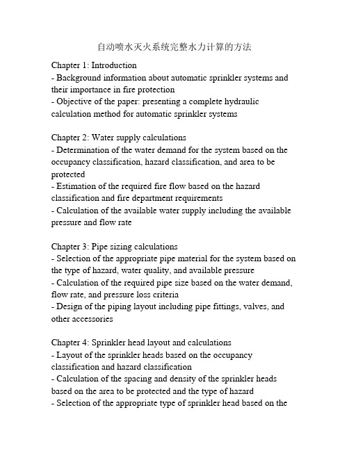
自动喷水灭火系统完整水力计算的方法Chapter 1: Introduction- Background information about automatic sprinkler systems and their importance in fire protection- Objective of the paper: presenting a complete hydraulic calculation method for automatic sprinkler systemsChapter 2: Water supply calculations- Determination of the water demand for the system based on the occupancy classification, hazard classification, and area to be protected- Estimation of the required fire flow based on the hazard classification and fire department requirements- Calculation of the available water supply including the available pressure and flow rateChapter 3: Pipe sizing calculations- Selection of the appropriate pipe material for the system based on the type of hazard, water quality, and available pressure- Calculation of the required pipe size based on the water demand, flow rate, and pressure loss criteria- Design of the piping layout including pipe fittings, valves, and other accessoriesChapter 4: Sprinkler head layout and calculations- Layout of the sprinkler heads based on the occupancy classification and hazard classification- Calculation of the spacing and density of the sprinkler heads based on the area to be protected and the type of hazard- Selection of the appropriate type of sprinkler head based on thetemperature rating, response time, and other factorsChapter 5: System testing and approval- Field testing of the system including pressure testing, flow testing, and functional testing of the sprinkler heads- Submission of the hydraulic calculations to the relevant authorities for approval- Conclusion and recommendations for future research in the field of hydraulic calculations for automatic sprinklersystems.Automatic sprinkler systems are an integral part of fire protection systems in buildings, warehouses, and industrial facilities. These systems are designed to detect and extinguish fires, protecting people, property, and assets from potential damage. Hydraulic calculations ensure that these systems are designed optimally to provide adequate water supply to all sprinkler heads in case of a fire.The objective of this paper is to provide a comprehensive overview of hydraulic calculations for automatic sprinkler systems. The paper will cover the principles and methodologies used to determine the water supply requirements, pipe sizing, sprinkler head layout, and system testing.The importance of automatic sprinkler systems cannot be overstated. They have been proven to significantly reduce the incidence of injuries, deaths, and property damage in fires. The National Fire Protection Association (NFPA) reports that buildings with sprinkler systems experience 60% fewer injuries, and 80% less property damage compared to buildings without sprinkler systems. These systems can also reduce the risk of fire spread,minimizing the impact of a fire on neighboring buildings and surrounding communities.The key to effective fire protection is the right design of the automatic sprinkler systems. This calls for hydraulic calculationsto determine the water supply requirements, pipe sizing, sprinkler head layout, and system testing. These calculations take into account the occupancy classification, hazard classification, and area to be protected. The determination of the water demand is based on the type of occupancy and the potential hazards associated with it.The water supply calculations also include the estimation of the required fire flow, which is the amount of water needed to control a fire until the fire department can respond. This is determined based on the hazard classification and fire department requirements. The calculation of the available water supply involves the assessment of the available pressure and flow rate, taking into account factors such as friction loss and elevation difference.Pipe sizing calculations are crucial to ensure that the water supply system can deliver adequate water to all sprinkler heads in case of a fire. The pipe size is calculated based on the water demand, flow rate, and pressure loss criteria. The selection of the appropriate pipe material is also important, taking into consideration factors such as the type of hazard, water quality, and available pressure. The layout of the sprinkler heads is an essential aspect of designing automatic sprinkler systems. The sprinkler head layout is determined based on the occupancy classification and hazardclassification. The spacing and density of the sprinkler heads are calculated according to the area to be protected and the type of hazard. The selection of the appropriate type of sprinkler head takes into consideration factors such as the temperature rating, response time, and other factors.System testing and approval are essential to ensure that the automatic sprinkler system is functional and meets the relevant standards and regulations. This includes field testing of the system, submission of the hydraulic calculations to the relevant authorities for approval, and ongoing maintenance of the system.In conclusion, automatic sprinkler systems are a critical aspect of fire protection. Their effectiveness, however, is directly tied to their design. Hydraulic calculations are essential in ensuring an optimal design of the system, taking into consideration the water supply requirements, pipe sizing, sprinkler head layout, and system testing. Continued research in this field will help to further improve the design of these systems, ultimately saving lives and property.Chapter 2: Principles and Methodologies of Hydraulic CalculationsHydraulic calculations are critical in designing an automatic sprinkler system that is effective and meets the relevant standards and regulations. This chapter provides an overview of the principles and methodologies of hydraulic calculations for automatic sprinkler systems, including water supply calculations, pipe sizing calculations, sprinkler head layout, and system testing. Water Supply CalculationsThe determination of the water supply requirements for an automatic sprinkler system is crucial in ensuring that the system is capable of delivering the required amount of water to all sprinkler heads in case of a fire. The water supply calculations take into account the occupancy classification, hazard classification, and the area to be protected.The water supply calculations involve the estimation of the required fire flow, which is the amount of water needed to control a fire until the fire department can respond. The required fire flow is determined based on the hazard classification and the fire department requirements. For example, a high-hazard occupancy such as a chemical storage facility may require a higher fire flow than a low-hazard occupancy such as an office building.The calculation of the available water supply involves the assessment of the available pressure and flow rate, taking into account factors such as friction loss and elevation difference. The available water supply is the maximum water supply that the system can draw from the water source.Pipe Sizing CalculationsPipe sizing calculations are essential in ensuring that the water supply system can deliver adequate water to all sprinkler heads in case of a fire. The pipe size is calculated based on the water demand, flow rate, and pressure loss criteria. The pipe sizing calculations take into account the type of pipe material, its capacity, and its friction loss.The selection of the appropriate pipe material is essential, taking into consideration factors such as the type of hazard, water quality, and available pressure. Common pipe materials used in automatic sprinkler systems include steel, PVC, and CPVC.The pipe sizing calculation involves the determination of the maximum allowable velocity, which is the maximum velocity at which water can flow through the pipe without causing damage to the pipe or impairing its effectiveness. The maximum allowable velocity is typically around 10 feet per second (fps) for steel pipes and 8 fps for plastic pipes.Sprinkler Head LayoutThe layout of the sprinkler heads is an essential aspect of designing an automatic sprinkler system. The sprinkler head layout is determined based on the occupancy classification and hazard classification. The spacing and density of the sprinkler heads are calculated according to the area to be protected and the type of hazard.The selection of the appropriate type of sprinkler head takes into consideration factors such as the temperature rating, response time, and other factors. Common types of sprinkler heads used in automatic sprinkler systems include pendent sprinklers, upright sprinklers, and sidewall sprinklers.System Testing and ApprovalSystem testing and approval are critical in ensuring that the automatic sprinkler system is functional and meets the relevant standards and regulations. System testing involves field testing of the system, including flow tests, pressure tests, and other functional tests.System approval involves the submission of the hydraulic calculations to the relevant authorities for approval. The hydraulic calculations need to meet the relevant standards and regulations, including those set by the National Fire Protection Association (NFPA). Ongoing maintenance of the system is essential in ensuring that the system remains functional and effective in case of a fire.In conclusion, hydraulic calculations are an essential aspect of designing an automatic sprinkler system that is effective and meets the relevant standards and regulations. The principles and methodologies of hydraulic calculations involve water supply calculations, pipe sizing calculations, sprinkler head layout, and system testing. Continued research in this field will help to further improve the design of these systems, ultimately saving lives and property.Chapter 3: Software for Hydraulic CalculationsHydraulic calculations for automatic sprinkler systems can be complex and time-consuming. Fortunately, there are many software programs available today that can simplify the process and help designers and engineers to perform these calculations quickly and accurately.This chapter discusses the software programs available forhydraulic calculations, their benefits, and limitations.Benefits of Software ProgramsThe use of software programs for hydraulic calculations offers numerous benefits, including:1. Efficiency: Software programs can perform complex calculations in a matter of seconds, saving designers and engineers time and effort.2. Accuracy: Software programs eliminate human error and ensure accurate calculation results. There is no possibility of miscalculations or mistakes during data entry.3. Flexibility: Software programs allow for easy modification of system parameters, such as the water supply or hazard classification, without having to recalculate the entire system.4. Collaboration: Software programs allow for easy sharing and collaboration between team members, enabling real-time design changes and feedback.5. Compliance: Software programs are often designed to meet relevant regulatory standards, ensuring that calculations are compliant with the National Fire Protection Association (NFPA) and other regulatory bodies.Limitations of Software ProgramsAlthough there are numerous benefits to using software programs for hydraulic calculations, there are also some limitations, including:1. Cost: Many software programs can be expensive, which may make them less accessible to smaller design firms or freelance designers.2. Learning Curve: There may be a learning curve associated with using new software programs, which may require additional training or support.3. Input Requirements: Software programs require accurate input data for proper calculations. If input data is inaccurate or incomplete, the results produced by the software may also be inaccurate.4. Simplification: Some software programs may simplify or reduce the complexity of hydraulic calculations, which can lead to oversights or mistakes in the design of the system.Popular Software ProgramsThere are many software programs available today for hydraulic calculations for automatic sprinkler systems. Some of the most popular software programs include:1. AutoSPRINK: AutoSPRINK is a comprehensive fire sprinkler design software used for hydraulics, 3D modeling, and fabrication. It is designed for engineers, contractors, and designers and featuresadvanced hydraulic calculations tools.2. HydraCAD: HydraCAD is a software program used for hydraulic calculations, 2D schematics, and fabrication. The software offers an intuitive interface, comprehensive libraries, and powerful calculation tools.3. SprinkCAD: SprinkCAD is a software program used for hydraulic calculations, design, and fabrication. It is designed for engineers, contractors, and designers and offers fast and accurate calculations.4. Elite Software Sprinkler Design: Elite Software Sprinkler Design is a software program used for hydraulic calculations, design, and fabrication. It is designed for engineers, contractors, and designers and offers an easy-to-use interface and advanced calculation tools.In conclusion, the use of software programs for hydraulic calculations for automatic sprinkler systems offers many benefits, including efficiency, accuracy, flexibility, collaboration, and compliance. However, designers and engineers should be aware of the potential limitations of using these software programs, such as cost, the learning curve, input requirements, and simplification of calculations. Ultimately, the selection of the appropriate software program will depend on the needs of the designer or engineer and the complexity of the project.Chapter 4: Factors to Consider When Selecting a Software Program for Hydraulic CalculationsWhen selecting a software program for hydraulic calculations forautomatic sprinkler systems, there are several factors to consider. This chapter discusses these factors and their importance in selecting the appropriate software program.1. Project Size and ComplexityThe size and complexity of the project can determine the type of software program needed. Some programs are designed for simple systems, while others are better suited for more complex systems. If the project involves multiple zones, complex pipe networks, or special hazard classifications, a more advanced software program may be necessary.2. Input Data RequirementsThe accuracy of the hydraulic calculations depends on the input data provided. Some software programs require specific details, such as pipe length, fittings, and flow rates. It is important to ensure that the input data is accurate and complete to achieve accurate results.3. Regulatory ComplianceHydraulic calculations for automatic sprinkler systems must comply with relevant regulatory standards, such as the National Fire Protection Association (NFPA) standards. It is important to select a software program that is designed to meet these regulatory standards to ensure compliance with local regulations and avoid potential penalties or legal issues.4. User InterfaceThe user interface of a software program can impact its usability and ease of use. It is important to select a program with an intuitive interface that provides clear and concise instructions, making it easy for the user to enter input data, select parameters, and interpret the results.5. PriceThe cost of the software program is an important factor to consider. Some programs can be expensive, while others are more affordable. It is important to select a program that fits within the budget, while still meeting the project's requirements.6. Technical SupportTechnical support is critical in ensuring that the software program operates effectively and efficiently. Select a software program that offers reliable technical support, including timely responses to inquiries, and easy-to-access resources such as user manuals or video tutorials.7. CompatibilityCompatibility with other software programs or systems can impact the ease of data transfer, which is important in collaborating with other team members or transferring data to other programs. Ensure that the software program is compatible with other software programs or systems used in the project.8. Additional FeaturesSome software programs offer additional features, such as 3D modeling or fabrication tools, that can enhance the design process. Consider whether additional features would be beneficial for the project, and whether the cost of the program justifies these additional features.In conclusion, selecting the appropriate software program for hydraulic calculations for automatic sprinkler systems requires careful consideration of several factors, including the size and complexity of the project, input data requirements, regulatory compliance, user interface, price, technical support, compatibility, and additional features. By evaluating these factors, designers and engineers can select a software program that meets their needs, increases efficiency, and ensures compliance with relevant regulatory standards.Chapter 5: Common Software Programs for Hydraulic CalculationsThere are many software programs available for hydraulic calculations for automatic sprinkler systems, each with its own advantages and disadvantages. This chapter discusses some of the most commonly used software programs and their features.1. HydratecHydratec is a widely used software program for hydraulic calculations for automatic sprinkler systems. It is known for its accuracy and reliability, and is compliant with relevant regulatorystandards, such as NFPA 13. Hydratec allows users to create and analyze complex hydraulic systems quickly and easily, and includes features such as pipe sizing, water demand calculations, and automatic pressure calculations. Hydratec also offers technical support and training resources.2. SprinkCADSprinkCAD is another popular software program for hydraulic calculations for automatic sprinkler systems. It features an intuitive interface and a range of design and analysis tools, including automatic pipe sizing, hydraulic balancing, and pressure drop calculations. SprinkCAD is also compliant with relevant regulatory standards, such as NFPA 13, and offers technical support and training resources.3. Elite FireElite Fire is a comprehensive software program for hydraulic calculations for automatic sprinkler systems. It includes advanced features such as hydraulic analysis, pipe size optimization, and pressure loss calculations, as well as 3D modeling and fabrication tools. Elite Fire is also compliant with relevant regulatory standards and offers technical support and training resources.4. Autodesk RevitAutodesk Revit is a 3D modeling software program that can be used for hydraulic calculations for automatic sprinkler systems. It allows users to create and analyze complex hydraulic systemswithin a 3D model of the building. Revit includes features such as automatic pipe sizing, hydraulic analysis, and pressure drop calculations. It is also compatible with other Autodesk software programs, such as AutoCAD and Navisworks.5. PipeDesigner 3DPipeDesigner 3D is a comprehensive software program that includes design tools for a range of mechanical systems, including automatic sprinkler systems. It features an intuitive interface, advanced modeling capabilities, and comprehensive calculations for pipe sizing, pressure drop, and water demand. PipeDesigner 3D is compliant with relevant regulatory standards and offers technical support and training resources.In conclusion, selecting the appropriate software program for hydraulic calculations for automatic sprinkler systems requires careful consideration of features, compatibility, ease of use, and regulatory compliance. It is important to select a program that meets the needs of the project and provides accurate and reliable results. By evaluating the features and benefits of software programs such as Hydratec, SprinkCAD, Elite Fire, Autodesk Revit, and PipeDesigner 3D, designers and engineers can select a program that suits their requirements, enhances the design process, and ensures regulatory compliance.。
自动喷水灭火系统计算
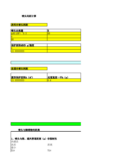
喷头间距计算房间内喷头间距喷头出流量Kq=K(10P)^0.580=80保护面积ABCD q/强度=13.33333333走道内喷头间距圆形保护面积A(㎡)走道宽度一半b(m)13.333333330.6喷头与障碍物间距离1、喷头与梁、通风管道距离(m)非强制性内插法高差距离最小X1=Y1=0.140.6X2=Y2=0.240.9最大值X3=Y3=0.140.9X4=Y4=0.24 1.2X=Y0.15最小值=0.63最大值=0.932、障碍物横截面小于750mm时距离(强制性)(mm)a≥ 70e=170b=1003、喷头与邻近障碍物最小水平距离(非强制性)管道沿程水头损失系数iMp/m q 管道消防给水设计流量L/s 0.00019963730管道长度L(m)544.0371586250 2.996E-070.000162994管道沿程水头损失hf(Mpa)0.0499092080.0002016560.050414022管径参考表减压孔板计算55.5491.5721公称直计算内计算内P(MPa)喷水强度(L/min.㎡)0.16正方形喷头边长(m)喷头间距S3.651483717 3.65保护半径R=√(A/3.14)喷头间距S=2√(R^2-b^2)2.0606514753.942732302R喷头有效保护面积2b走道宽度4、梁、通风管道、桥架、成排管道(强制性)C 海森威廉系数di(计算内径)m1200.1557089.9580850.0001140030.808274798参考v i1.59070.000305583Hk(MPa)ζ1Vk(m/s)0.0755.5496 1.572141546输入ζ155.54959817Vk(m/s)Q(m^3/s)Q(l/s)1.5721415460.0296529.65输入公称直径(mm)DN50DN70计算内径(mm)dj5267计算内径(m)dj0.520.67注:Hk是确定的,即若本层入口压力为38mH2O,要控制压力为注:当b不是走道一半时,取较长边hf0.076395712输入压力为32mH2O,Hk为6mH2O(米水柱)也是剩余压力,减压孔板减掉的压力值。
消火栓自动喷洒课程设计计算书
2.喷头应设在顶板或吊顶下易于接触到火灾热烟气流,并利于均匀喷洒水量的位置,应防止障碍物屏障热烟气流和破坏喷头洒水分布。
3.除吊顶型喷头及吊顶下安装的喷头外,直立型、下垂型标准喷头,其溅水盘与顶板的间距,不应小于75mm,其不应大于150mm。
4.装置喷头的场所注意防止腐蚀气体的侵入,不受外力打击,要定期清除喷头上的尘土。
此次设计主要参考了《自动喷水灭火系统设计规范》和《建筑给排水设计手册》等,其余参考书详见参考书目。
第
1.1
商场楼占地面积约为981平方米。有地下室,地上部分公有7层,建筑高度为28.8m。
地下一层为消防房和设备间,一至六层为超市,七层为水箱间。
1.2 消火栓系统的组成
消火栓系统由消防泵、消防管网、消火栓组成。
i—管道单位长度的水头损失
局部水头损失按沿程的 计算
6.2点消火栓出水量
6.0L/s
7.2-3管段的流量Q Q1+Q2 6.0+5.2 11.2L/s
8.3-4管段的流量Q Q1+Q2 11.2L/s
9.4-5管段的流量Q Q1+Q2+5 16.2L/s
10.5-6管段的流量Q Q1+Q2+5 16.2L/s
H1—室内最高着火点离地面高度(m);
H2—从水枪喷嘴离地面高度(m),一般取lm。
水枪的上倾角一般按45°计算,则
消火栓布置保护半径计算:
(m)
在消火栓平面布置时,结合建筑平面图,以22.6m为消火栓保护半径,室内消火栓应设在明显易于取用的地点.
栓口离地面高度宜为1.1m,其出水方向宜与设置25m,水枪喷嘴口径19mm。
自动灭火喷淋系统水力计算

自动灭火喷淋系统水力计算
水力计算自动喷水灭火系统的水力计算主要是按照逐点计算法进行计算;这于原规范有很大区别。
原规范是采用估算法进行计算的。
计算方法:1、确定喷头间距规范中给出了如下面所示的间距。
这个间距是最大间距,也就是在0.1Mpa下的间距。
喷水强度
(L/min·m2)正方形布置的边长(m)矩形或平行四边形布置的长边边长(m)一只喷头的最大保护面积(m2)喷头与端墙的最大距离(m)
44.44.520.02.263.64.012.51.883.43.611.51.712~203.03.69.01.5注:1 仅在走道设置单排喷头的闭式系统,其喷头间距应按走道地面不留漏喷空白点确定;
2 货架内喷头的间距不应小于2m,并不应大于3m。
自喷计算书 K
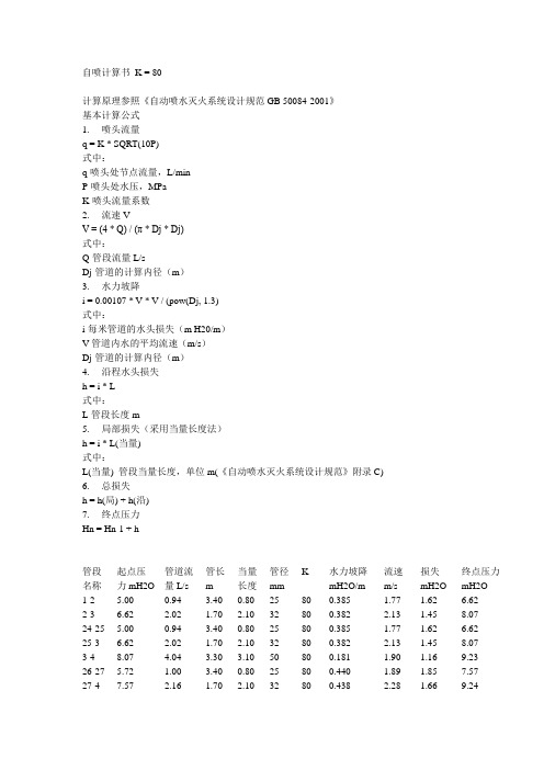
自喷计算书K = 80计算原理参照《自动喷水灭火系统设计规范GB 50084-2001》基本计算公式1. 喷头流量q = K * SQRT(10P)式中:q-喷头处节点流量,L/minP-喷头处水压,MPaK-喷头流量系数2. 流速VV = (4 * Q) / (π * Dj * Dj)式中:Q-管段流量L/sDj-管道的计算内径(m)3. 水力坡降i = 0.00107 * V * V / (pow(Dj, 1.3)式中:i-每米管道的水头损失(m H20/m)V-管道内水的平均流速(m/s)Dj-管道的计算内径(m)4. 沿程水头损失h = i * L式中:L-管段长度m5. 局部损失(采用当量长度法)h = i * L(当量)式中:L(当量) 管段当量长度,单位m(《自动喷水灭火系统设计规范》附录C)6. 总损失h = h(局) + h(沿)7. 终点压力Hn = Hn-1 + h管段名称起点压力mH2O管道流量L/s管长m当量长度管径mmK 水力坡降mH2O/m流速m/s损失mH2O终点压力mH2O1-2 5.00 0.94 3.40 0.80 25 80 0.385 1.77 1.62 6.62 2-3 6.62 2.02 1.70 2.10 32 80 0.382 2.13 1.45 8.07 24-25 5.00 0.94 3.40 0.80 25 80 0.385 1.77 1.62 6.62 25-3 6.62 2.02 1.70 2.10 32 80 0.382 2.13 1.45 8.07 3-4 8.07 4.04 3.30 3.10 50 80 0.181 1.90 1.16 9.23 26-27 5.72 1.00 3.40 0.80 25 80 0.440 1.89 1.85 7.57 27-4 7.57 2.16 1.70 2.10 32 80 0.438 2.28 1.66 9.2428-29 5.72 1.00 3.40 0.80 25 80 0.440 1.89 1.85 7.57 29-4 7.57 2.16 1.70 2.10 32 80 0.438 2.28 1.66 9.24 4-5 9.23 8.36 2.31 3.10 50 80 0.774 3.94 4.19 13.42 5-6 13.42 8.36 13.60 1.50 50 80 0.774 3.94 11.69 25.11 6-7 25.11 8.36 1.09 2.10 50 80 0.774 3.94 2.47 27.57 30-31 8.57 1.23 3.40 0.80 25 80 0.660 2.32 2.77 11.34 31-32 11.34 2.64 3.40 2.10 32 80 0.656 2.79 3.61 14.95 32-33 14.95 4.27 3.40 2.70 40 80 0.810 3.40 4.94 19.89 33-34 19.89 6.14 3.40 3.10 50 80 0.418 2.89 2.71 22.60 34-35 22.60 6.14 3.40 3.10 50 80 0.418 2.89 2.71 25.32 35-7 25.32 6.14 1.70 3.70 50 80 0.418 2.89 2.26 27.57 7-8 27.57 14.50 3.40 4.60 80 80 0.245 2.92 1.96 29.54 36-37 9.18 1.27 3.40 0.80 25 80 0.707 2.40 2.97 12.15 37-38 12.15 2.74 3.40 2.10 32 80 0.702 2.89 3.86 16.01 38-39 16.01 4.42 3.40 2.70 40 80 0.868 3.51 5.29 21.30 39-40 21.30 6.36 3.40 3.10 50 80 0.447 2.99 2.91 24.21 40-41 24.21 6.36 3.40 3.10 50 80 0.447 2.99 2.91 27.12 41-8 27.12 6.36 1.70 3.70 50 80 0.447 2.99 2.42 29.54 8-9 29.54 20.86 3.40 5.40 80 80 0.508 4.20 4.47 34.01 42-43 10.54 1.36 3.40 0.80 25 80 0.811 2.57 3.41 13.94 43-44 13.94 2.93 3.40 2.10 32 80 0.806 3.09 4.43 18.38 44-45 18.38 4.73 3.40 2.70 40 80 0.996 3.77 6.08 24.45 45-46 24.45 6.81 3.40 3.10 50 80 0.514 3.21 3.34 27.79 46-47 27.79 6.81 3.40 3.10 50 80 0.514 3.21 3.34 31.13 47-9 31.13 6.81 1.70 3.90 50 80 0.514 3.21 2.88 34.01 9-10 34.01 27.67 3.40 6.10 100 80 0.205 3.19 1.94 35.95 10-11 35.95 27.67 3.40 0.00 100 80 0.205 3.19 0.70 36.64 11-12 36.64 27.67 3.40 0.00 150 80 0.026 1.47 0.09 36.73 12-13 36.73 27.67 3.40 0.00 150 80 0.026 1.47 0.09 36.82 13-14 36.82 27.67 3.40 0.00 150 80 0.026 1.47 0.09 36.91 14-15 36.91 27.67 3.68 0.00 150 80 0.026 1.47 0.10 37.00 15-16 37.00 27.67 3.40 0.00 150 80 0.026 1.47 0.09 37.09 16-17 37.09 27.67 2.15 0.00 150 80 0.026 1.47 0.06 37.15 17-18 37.15 27.67 21.90 0.00 150 80 0.026 1.47 0.57 37.72 18-19 37.72 27.67 3.20 0.00 150 80 0.026 1.47 0.08 37.80 19-20 37.80 27.67 3.20 0.00 150 80 0.026 1.47 0.08 37.88 20-21 37.88 27.67 3.20 0.00 150 80 0.026 1.47 0.08 37.97 21-22 37.97 27.67 3.20 0.00 150 80 0.026 1.47 0.08 38.05 22-23 38.05 27.67 1.69 0.00 150 80 0.026 1.47 0.04 38.09计算结果:所选作用面积:160.1平方米总流量:27.67 L/s平均喷水强度:10.37 L/min.平方米入口压力:38.09 米水柱。
水喷雾灭火系统水力计算书
xx大厦直燃机房水喷雾灭火系统设计说明1、确定保护对象的设计喷雾强度:燃气直燃机房保护目的为冷却,设计喷雾强度为9L/min.m2,持续喷雾强度为1小时。
2、计算保护面积S:根据《喷雾规范》第3.1.5条,保护面积应按保护对象外表面积确定。
直燃机其外形尺寸为:L=3.5米、B=1.9米、H=2.0m。
S=(1.9+3.5)*2*2+3.5*1.9=28.25m23、计算水雾喷头的流量q:要计算水雾喷头的流量q,首先要确定水雾喷头型号。
为了节约投资应选雾化角较大的喷头,其在相同的水压下保护面积较大。
水雾喷头选用ZSTWB-16-120型水雾喷头,该喷射器雾化角120度,流量适中,K=16。
q=K·(10·P)0.5,P=0.35 MPa (《喷雾规范》要求)q=16*(10*0.35)0.5≈30L/ min(1)计算所需水雾喷头的最小数量N:N=s·W /q=28.25*9/30≈9个4、喷头布置合理地布置水雾喷头,可以使喷雾均匀地完全覆盖保护对象,确保喷雾强度。
《喷雾规范》第3.2.3条规定“水雾喷头与保护对象之间的距离不得大于水雾喷头的有效射程。
”第3.2.4条规定“水雾喷头的平面布置方式可为矩形或菱形。
当按矩形布置时,水雾喷头之间的距离不应大于1.4倍水雾喷头的水雾锥底圆半径;当按菱形布置时,水雾喷头之间的距离不应大于1.7倍水雾喷头的水雾锥底圆半径。
”故应根据喷头有效射程、水雾锥度圆半径来布置喷头,也就是说水雾要直接喷射到保护对象并完全覆盖。
本设计按矩形布置喷头,为了达到直接喷射的目的,一台直燃机设置了14个喷头。
喷头布置后,经校核喷头间距、水雾覆盖情况,完全满足规范要求。
水雾锥底圆半径R为1.21m(B:0.7、θ:120°)。
喷头间距应小于1.4R=1.4*1.21=1.7m由平面及系统图可知喷头间距全部小于1.70米。
5、水泵流量Q=1.1*30L/min*14*2=14.4L/S参考文献:1.《水喷雾灭火系统设计规范》2.《建筑给水排水设计手册》3.《建筑设计防火规范》。
02-4自动喷水灭火系统的水力计算

后退
前进
返回本章总目录
返回本书总目录
第2章 建筑消防系统 2.4 自动喷水灭火系统的水力计算
2.4.1
闭式自动喷水消防系统设计基本参数及水力计算
应按该喷头处的水压计算确定 保证: 堆垛与货架储物仓库自动 喷水灭火系统的基本设计数 据和计算用水量表 和
点击查看
为确保安全,严重危险级作用面积内每个喷头出流量:
2.4.1
闭式自动喷水消防系统设计基本参数及水力计算
②根据喷头处压力求出流量公式:
Q喷 k喷 (10 p喷 )
式中
0.5
Q喷 ——喷头出流量,L/min; k喷 ——喷头的流量系数;
p喷 ——喷头处压力,MPa。
后退
前进
返回本章总目录
返回本书总目录
第2章 建筑消防系统 2.4 自动喷水灭火系统的水力计算
第2章 建筑消防系统 2.4 自动喷水灭火系统的水力计算
2.4.1
闭式自动喷水消防系统设计基本参数及水力计算
5)减压设施的计算:减压孔板、减压阀的水头损失计算同消 火栓消防给水系统。 节流管水头损失按下式计算:
u节 L P节 0.01 0.0000107 1.3 2g d节
式中 ΔP节——节流管的水头损失,MPa;
- 1、下载文档前请自行甄别文档内容的完整性,平台不提供额外的编辑、内容补充、找答案等附加服务。
- 2、"仅部分预览"的文档,不可在线预览部分如存在完整性等问题,可反馈申请退款(可完整预览的文档不适用该条件!)。
- 3、如文档侵犯您的权益,请联系客服反馈,我们会尽快为您处理(人工客服工作时间:9:00-18:30)。
自动喷水灭火系统的计算书1. 自动喷水灭火水力计算的基本数据1.1喷头的选择 《自动喷洒灭火系统设计规范》,闭式湿式自动喷水灭火系统适用范围:因管网及喷头中充水,故适用于环境温度为4~700C 之间的建筑物内,所以选用闭式湿式喷头。
1.2根据湿式系统、预作用系统不宜超过800只;本系统设四个湿式报警阀,每个报阀组控制的最不利喷头处,都设末端试水装置,每层最不利喷头处均设直径为25mm 的试水阀。
1.3 1.3水力计算查高规,选用边墙型扩展覆盖喷头工作压力0.1Mpa 为喷头最低工作压力,自动喷水灭火系统的基本设计数据见下表: 1).标准喷头:选用ZSTZ-15型快速响应喷头2)边墙型扩展覆盖喷头:选用ZSTYB-20型快速响应喷头,工作压力0.1,保护范围4.4×4.5m3)标准型喷头管径确定如下表表3-19 自动喷洒管径确定表喷头数 1 3 4 8 12 32 64 公称直径(mm) DN25DN32DN40DN50DN70DN80DN1004)水力计算方案一下图为自动喷水水力计算简图火灾危险等级 设计喷水强度[L/(min ·m 2)] 作用面积/m 2喷头工作压力/MPa 设计喷量/(L/s) 喷头间 距/m 每支喷头最大保护面积/m 2喷头与墙柱最大间距/m 中危险Ⅰ级61600.129.453.611.51.8下表为自动喷水水力计算表管段名称起点压力mH2O管道流量L/s管长m当量长度管径mmK 水力坡降mH2O/m流速m/s损失mH2O终点压力mH2O1-2 10.00 1.91 1.32 0.60 25 115 1.591 3.60 3.05 13.05 2-3 13.05 1.91 1.18 0.80 25 80 1.591 3.60 3.14 16.20 21-22 11.09 2.01 0.94 0.60 25 115 1.765 3.79 2.71 13.81 22-3 13.81 2.01 0.54 0.80 25 80 1.765 3.79 2.36 16.17 3-4 16.20 3.92 1.40 2.10 32 80 1.441 4.13 5.05 21.24 23-4 18.59 1.81 1.22 0.60 25 80 1.431 3.41 2.60 21.20 24-4 19.84 1.87 0.34 0.60 25 80 1.527 3.52 1.44 21.29 4-5 21.24 7.60 1.94 3.10 50 80 0.640 3.58 3.23 24.47 25-26 16.88 1.73 2.25 0.80 25 80 1.299 3.25 3.96 20.84 26-5 20.84 3.64 0.75 2.10 32 80 1.244 3.84 3.54 24.38 27-5 19.53 1.86 2.65 0.60 25 80 1.503 3.50 4.89 24.42 5-6 24.47 13.10 0.43 3.10 50 80 1.901 6.17 6.71 31.18 6-7 31.18 13.10 1.22 0.00 50 80 1.901 6.17 2.31 33.49 7-8 33.49 13.10 2.72 2.10 50 80 1.901 6.17 9.16 42.65 8-9 42.65 13.10 4.23 0.00 80 80 0.200 2.64 0.85 43.50 28-29 14.66 2.31 1.32 0.60 25 115 2.332 4.35 4.48 19.14 29-30 19.14 2.31 0.93 0.80 25 80 2.332 4.35 4.03 23.17 33-34 15.47 2.37 0.94 0.60 25 115 2.460 4.47 3.78 19.25 34-30 19.25 2.37 0.78 0.80 25 80 2.460 4.47 3.90 23.1530-31 23.17 4.69 1.38 2.10 32 80 2.060 4.94 7.18 30.34 35-31 26.72 2.17 1.17 0.60 25 80 2.057 4.09 3.63 30.35 36-31 28.13 2.23 0.39 0.60 25 80 2.165 4.20 2.15 30.27 31-32 30.34 9.08 1.94 3.10 50 80 0.914 4.28 4.61 34.95 37-32 29.06 2.26 2.01 0.60 25 80 2.237 4.26 5.83 34.89 38-32 30.31 2.31 1.39 0.60 25 80 2.333 4.36 4.65 34.96 32-9 34.95 13.66 0.44 3.70 50 80 2.067 6.43 8.55 43.50 9-10 43.50 26.76 5.62 5.40 80 80 0.836 5.39 9.21 52.71 10-11 52.71 26.76 1.84 0.00 100 80 0.191 3.09 0.35 53.06 39-11 40.00 2.66 1.76 1.40 32 80 0.662 2.80 2.09 42.09 11-12 53.06 29.42 2.65 6.10 100 80 0.231 3.40 2.02 55.09 12-13 55.09 29.42 1.83 1.10 100 80 0.231 3.40 0.68 55.77 13-14 55.77 29.42 0.47 0.00 125 80 0.075 2.22 0.03 55.80 14-15 55.80 29.42 0.02 3.70 125 80 0.075 2.22 0.28 56.08 15-16 56.08 29.42 3.06 0.00 125 80 0.075 2.22 0.23 56.31 16-17 56.31 29.42 2.95 3.70 125 80 0.075 2.22 0.50 56.80 17-18 56.80 29.42 0.63 0.00 125 80 0.075 2.22 0.05 56.85 18-19 56.85 29.42 4.70 3.70 125 80 0.075 2.22 0.63 57.47 19-20 57.47 29.42 0.69 0.00 125 80 0.075 2.22 0.05 57.53计算结果:所选作用面积:160.0平方米总流量:29.42 L/s平均喷水强度:11.03 L/min.平方米入口压力:57.53 米水柱水泵扬程为:H=Hr+Hz+报警阀损失+1.1×∑h=7.43+61+5+2+57.57= 133.米水柱Hr 入口压力Hz 水泵吸入口至入口静水压(按本工程确定层高计算为61m)∑h水泵吸入口至入口沿程及局部水头损失(管道长度+当量长度=195m,按干管管径选用DN150计算)7.43米水柱报警阀水头损失取0.04Mpa,水流指示器取0.02Mpa,方案二下图为自动喷水水力计算简图下表为自动喷水水力计算表管段名称起点压力mH2O管道流量L/s管长m当量长度管径mmK 水力坡降mH2O/m流速m/s损失mH2O终点压力mH2O1-2 10.00 1.91 1.32 0.90 32 115 0.342 2.01 0.76 10.76 2-3 10.76 1.91 1.18 1.20 32 80 0.342 2.01 0.81 11.57 21-22 10.31 1.94 0.94 0.90 32 115 0.353 2.04 0.65 10.96 22-3 10.96 1.94 0.54 1.20 32 80 0.353 2.04 0.61 11.57 3-4 11.57 3.85 1.40 2.70 40 80 0.659 3.06 2.70 14.27 23-4 12.50 1.48 1.22 0.60 25 80 0.962 2.80 1.75 14.25 24-4 13.28 1.53 0.34 0.60 25 80 1.022 2.88 0.96 14.25 4-5 14.27 6.86 1.94 3.10 50 80 0.522 3.23 2.63 16.90 25-26 11.72 1.44 2.25 0.80 25 80 0.902 2.71 2.75 14.47 26-5 14.47 3.04 0.75 2.10 32 80 0.864 3.20 2.46 16.93 27-5 13.59 1.55 2.65 0.60 25 80 1.046 2.92 3.40 17.00 5-6 16.90 11.45 0.43 3.10 50 80 1.451 5.39 5.13 22.03 6-7 22.03 11.45 1.22 0.00 50 80 1.451 5.39 1.76 23.79 7-8 23.79 11.45 2.72 2.10 50 80 1.451 5.39 6.99 30.78 8-9 30.78 11.45 4.23 0.00 80 80 0.153 2.31 0.65 31.43 28-29 14.72 2.32 1.32 0.90 32 115 0.503 2.44 1.12 15.8329-30 15.83 2.32 0.93 1.20 32 80 0.503 2.44 1.07 16.90 33-34 15.00 2.34 0.94 0.90 32 115 0.513 2.47 0.94 15.94 34-30 15.94 2.34 0.78 1.20 32 80 0.513 2.47 1.02 16.96 30-31 16.90 4.65 1.38 2.70 40 80 0.964 3.70 3.94 20.84 35-31 18.28 1.80 1.17 0.60 25 80 1.407 3.38 2.49 20.77 36-31 19.38 1.85 0.39 0.60 25 80 1.491 3.48 1.48 20.86 31-32 20.84 8.30 1.94 3.10 50 80 0.763 3.91 3.85 24.68 37-32 20.63 1.91 2.01 0.60 25 80 1.588 3.59 4.14 24.76 38-32 21.41 1.94 1.39 0.60 25 80 1.648 3.66 3.28 24.69 32-9 24.68 12.15 0.44 3.70 50 80 1.635 5.72 6.76 31.45 9-10 31.43 23.60 5.62 5.40 80 80 0.650 4.75 7.16 38.60 10-11 38.60 23.60 1.84 0.00 100 80 0.149 2.73 0.27 38.87 39-11 36.88 2.55 1.76 1.40 32 80 0.610 2.69 1.93 38.80 11-12 38.87 26.15 2.65 6.10 100 80 0.183 3.02 1.60 40.47 12-13 40.47 26.15 1.83 1.10 100 80 0.183 3.02 0.53 41.00 13-14 41.00 26.15 0.47 0.00 125 80 0.059 1.97 0.03 41.03 14-15 41.03 26.15 0.02 3.70 125 80 0.059 1.97 0.22 41.25 15-16 41.25 26.15 3.06 0.00 125 80 0.059 1.97 0.18 41.43 16-17 41.43 26.15 2.95 3.70 125 80 0.059 1.97 0.39 41.82 17-18 41.82 26.15 0.63 0.00 125 80 0.059 1.97 0.04 41.86 18-19 41.86 26.15 4.70 5.00 125 80 0.059 1.97 0.57 42.43 19-2042.4326.150.690.00150800.0231.390.0242.45计算结果:所选作用面积:160.0平方米 总流量:26.15 L/s平均喷水强度:9.81 L/min.平方米 入口压力:42.45 米水柱水泵扬程为:H=Hr+Hz+报警阀损失+1.1×∑h =7.43+69.6+1.5+2+42.45=122.95米水柱 Hr 入口压力Hz 水泵吸入口至入口静水压(按本工程确定层高计算为69.6m,水池在地下一层)∑h 水泵吸入口至入口沿程及局部水头损失(管道长度+当量长度=195m,按干管管径选用DN150计算)7.43米水柱报警阀压力损失 210Q B H k k =[4](3-25)式中 H k —报警阀压力损失,KPa ;B kl —报警阀的阻力系数,DN150湿式报警阀,B kl =0.000869OmH kpa Q H k 222469.169.1410)12.41(000869.010000869.0==⨯⨯=⨯=水流指示器取0.02Mpa , 比较两方案因方案一,所计算水泵扬程超出原喷淋泵扬程,故选用方案二所确定的喷淋管径。