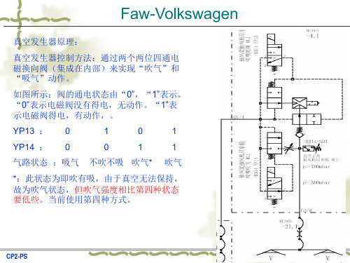
Schmalz vs-v-d-pnp真空发生器说明书中文
真空发生器
CP2-PS
Faw-Volkswagen
措施--硬件
1. 更改电柜内部接线。将操作面板XL4.1、XL4.2、XL4.3、XL4.4内控制真空发生器电磁 阀输出的电源模块供电线路进行改接,原来的+658并接至+660、-659并接至-661,即 由原来的“g级别”更改为“j级别”。 添加“真空发生器测试”按钮,实现在开门状态下,人为选择该功能,进行真空发生 器的压力测试。
CP2-PS
Faw-Volkswagen
FC343: 添加DB292.DBX1.6和M343.3 是机械手在停车位置时,对M342.4复位,即在开门时, 不能对真空发生器进行操作,此功能时放置误操作。M343.3是操作面板按钮选择(真 空发生器测试按钮),
பைடு நூலகம்
CP2-PS
Faw-Volkswagen
Faw-Volkswagen
(1)
(1)
(2)
图为自动化运行模式:
改进前:E047.02为自动化模式,M081.10为整线安全,如果整线安全不正常,例如:安全门打开,则所有真空发生器都要进行“吸 改进前 气”动作。 改进后: 改进后:可以将“整线安全区域”(1)替换成“压机局部区域安全保护”(2)。这样在单台压机开门时,保证其他区域的安全是 正常的,从而当局部安全区域不正常时,其他真空发生器不进行“吸气”动作。同时添加机械手角度的位置监控,若机械手
气路状态 :吸气
不吹不吸 吹气*
*:此状态为即吹有吸,由于真空无法保持, 故为吹气状态,但吹气强度相比第四种状态 要低些。当前使用第四种方式。
CP2-PS
Faw-Volkswagen
• • •
• •
改 进 前 后 对 比
施迈茨真空讲座

搬运碟形的不平整的工件,如:汽车金属板,纸箱,塑料 件,铝箔/热塑包装的产品,电子零件。
2020/8/8
Innovative Vacuum Automation
16
真空吸盘
- 主要类型 -
波纹吸盘
波纹吸盘的技术参数
• 当在相同的直径下,为什么波纹吸盘的吸力小于扁平吸盘? • 有效的吸取面积:
典型的应用区域: 搬运狭长而且抓取面很小的工件:如 管件,几何形工 件,木条,窗架,纸箱,锡箔/热塑包装的产品。
2020/8/8
Innovative Vacuum Automation
18
真空吸盘
- 材料 -
选择真空吸盘的材料
标准 • 抗磨损耐用 • 柔韧性防止永久变形 • 抗侵蚀性 • 可抵抗: – 臭氧 –油 – 燃料 – 酒精 和乙醇 – 溶剂 – 酸性物质 • 抗高温 (短期/长期) • 不含硅胶 • 不含 PWIS(水性油漆干扰物) • 肖氏硬度 • 冲压行业 • 可用于食品行业
6
真空技术基础知识
-工业搬运中的真空 真空系统的组成元件
真空发生器
过滤和连接部件
安装部件
2020/8/8
开关和系统监控
控制阀技术
真空吸盘
Innovative Vacuum Automation
7
真空吸盘
真空吸盘
2020/8/8
Innovative Vacuum Automation
8
真空吸盘 - 应用和重要性 -
2020/8/8
Innovative Vacuum Automation
25
真空发生器
-气动式真空发生器 -
施迈茨真空发生器SXMP30操作说明

一、复位
1、按住“MENU”键约5秒,直到出现3个“0”闪烁
2、按向上键1次,出现“001”
3、按回车键3次后,再按向上键或向下键找到“SEt”
4、按回车键1次,再按向上键或向下键找到出现“rES”
5、按住回车键,直到“rES”闪烁,复位完成。
(即恢复出厂设置)
二、清零(即将当前大气压调为0)
1、按“MENU”键1次,再按再按向上键或向下键找到“CAL”
2、按回车键1次,出现“0”,清零完成。
1、按住“MENU”键约5秒,直到出现3个“0”闪烁
2、按向上键1次,出现“001”
3、按回车键3次后,再按向上键或向下键找到“bLo”
4、按回车键1次后, 再按向上键或向下键找到“E-t”
5、按回车键1次确认。
1、按“MENU”键1次,再按向上键或向下键找到“tbL”
2、按回车键1次,出现“10”即原厂设置吹气时间是0.10秒
3、根据需要,再按向上键或向下键设定吹气时间后,按回车键1次确认。
(设定范围是0.01 到2.5秒,显示为1~250)
注意:通过上述两个步骤就可以设定外部吹气的时间,不再需要改变机械手的程序中加时间延迟了。
若设定外部吹气功能和时间后进行过复位,外部吹气功能会被取消,回到出厂设置,需要重新设置。
臭氧发生器说明书

第一章节重要声明本使用资料着作权属广州佳环电器科技有限公司所有,未经本公司书面许可,任何单位或个人不得以任何方式摘录、复制或翻译,侵权必究。
广州佳环电器科技有限公司保留修改本说明书技术参数及规格的权力,对本说明书中的印刷错误及与最新资料不符之处我们会及时改进。
所有改动不再事先通知,但会编入新版使用说明中。
广州佳环电器科技有限公司保留对本说明书的最终解释权。
本使用说明书中的图示都是为了说明的需要而绘制的,可能会与真实新产品略有差别,这取决于技术改进的实际情况和新产品生产的具体时间,如果说明书所述内容与您的产品不符,请以产品为准。
注意事项请勿在高精度电子设备附近使用本产品,电波干扰可能引起高精度电子设备的误操作和其他问题。
尤其在以下设备附近需特别注意:助听器、起搏器和其他医疗电子设备、火灾探测器、其他精度自动控制装置。
不要拆卸或改装本产品,否则会造成本产品的损坏、漏电和电路故障。
避免过度受潮,水或其他液体进入本产品可能引起本产品漏电和故障。
避免用挥发性的溶液或有机溶剂擦拭设备,可能会损坏设备的表面。
合格的专用接地线,安全可靠的接地,使用的线路的容量是符合要求的,以确保消除火灾隐患。
设备安装人员必须经过培训才能开机维修。
使用臭氧时,严禁工作人员在高浓度臭氧空间环境中上班工作,工作人员在超过相关标准的臭氧浓度的空间环境中上班在应要有防护措施。
切记设备保养或维修时必须在断电和泄尽气压状态下进行,确保人员安全维修。
使用本产品的环境条件要求:1.1室内应无易燃易爆气体及导电粉尘。
禁止安装在氨气易泄露或有发生爆炸危险的危险区域室内有220V/50HZ交流电源。
部分臭氧设备同时需要用到380V/50Hz交流电源环境温度要求:-10℃-33℃环境湿度要求:≤55%。
放置本机的地面要求平整,注意将设备平稳放在地上或支架上。
设备安装时保持设备工作环境通风及空气干燥,该空间须安装排风扇或空调。
免费声明:对于超越我们责任能力范围的由自然灾害(如:地震、水灾等)或者任何行为和事故(包括在这些意外或其他异常情况下,用户故意或意外的滥用)而导致的损失,本公司不承担任何责任。
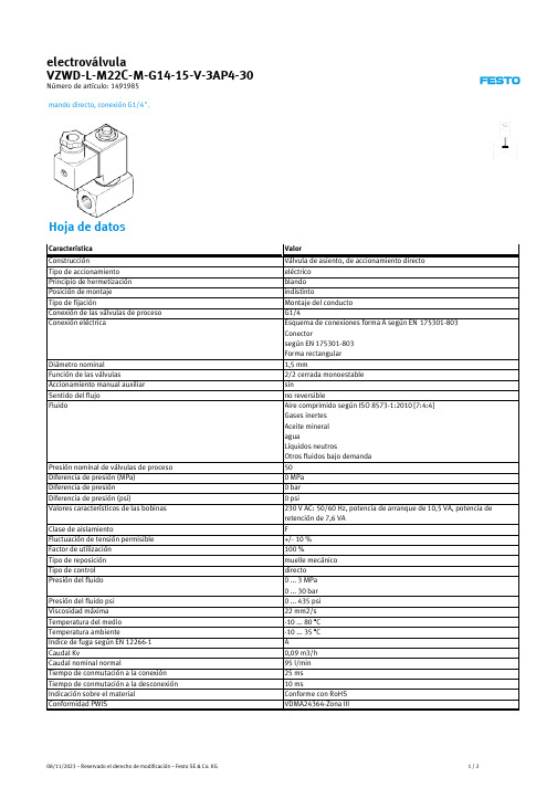
Festo VZWD-L-M22C-M-G14-15-V-3AP4-30 商品说明书
Presión nominal de válvulas de proceso Diferencia de preห้องสมุดไป่ตู้ión (MPa) Diferencia de presión Diferencia de presión (psi) Valores característicos de las bobinas
electroválvula VZWD-L-M22C-M-G14-15-V-3AP4-30
Número de artículo: 1491985
mando directo, conexión G1/4".
Hoja de datos
Característica Construcción Tipo de accionamiento Principio de hermetización Posición de montaje Tipo de fijación Conexión de las válvulas de proceso Conexión eléctrica
Clase de aislamiento Fluctuación de tensión permisible Factor de utilización Tipo de reposición Tipo de control Presión del fluido
Presión del fluido psi Viscosidad máxima Temperatura del medio Temperatura ambiente Índice de fuga según EN 12266-1 Caudal Kv Caudal nominal normal Tiempo de conmutación a la conexión Tiempo de conmutación a la desconexión Indicación sobre el material Conformidad PWIS
斯姆勒斯(Sumulees) SV50、SV50H无音缸猎犬真空吸盘方便指南说明书

T h a n k Y o u f o r S e l e c t i n gOperator Owner's Manual1BAG LINER OPTIONS (Samples supplied with unit)Felt Filter P/N 890435For use in all dusty conditions. Can beused with other liners For use on hard surface where a variety of PACKAGED SINGLYSPECIFICATION SSV50SV50H H.P. 6.0 (4.47 Kw ) 5.5 (4.1kW)TYPE B&S INTEK H O NDA O FU EL CAP. 1.6q t. (1.5L) 1.2q t. (1.1L)O IL CAP.0.69q t. (0.65L)0.63q t. (0.60L)HT:U NIT 145# (65.8kg)153# (69.4kg)HT:SHIPPING 168# (76.2kg)176# (79.8kg)INE WEIG HT:28# (12.7kg)36# (16.3kg)NIT LENG TH 62" (1.57m)62" (1.57m)NIT WIDTH 26.75" (0.68m)26.75" (0.68m)EIG HT42" (1.07m)42" (1.07m)IN THE INTEREST OF SAFETYWARNING: DO NOT1. DO NOT run engine in an enclosed area.Exhaust gases contain carbon monoxide, an odorless and deadly poison.2. DO NOT place hands or feet near moving or rotating parts.3. DO NOT store, spill or use gasoline near an open flame, or devices such as a stove,furnace, or water heater which use a pilot light or devices which can create a spark.4. DO NOT refuel indoors where area is not well ventilated. Outdoor refueling is recommended.5. DO NOT fill fuel tank while engine is running. Allow engine to cool for 2 minutes before refueling. Store fuel in approved safety containers.6. DO NOT remove fuel tank cap while engine is running.7. DO NOT operate engine when smell of gasoline is present or other explosive conditions exist.8. DO NOT operate engine if gasoline is spilled. Move machine away from the spill and avoid creating any ignition until the gasoline has evaporated.9. DO NOT transport unit with fuel in tank.10. DO NOT smoke when filling fuel tank.11. DO NOT choke carburetor to stop engine. Whenever possible, gradually reduce engine speed before stopping.12. DO NOT run engine at excessive speeds. This may result in injury & /or damage to unit.13. DO NOT tamper with governor springs,governor links or other parts which may change the governed engine speed.14. DO NOT tamper with the engine speed selected by the engine manufacturer.15. DO NOT check for spark with spark plug or spark plug wire removed. Use an approved tester.16. DO NOT crank engine with spark plug removed. If engine is flooded, place throttle in “FAST” position and crank until engine starts.17. DO NO T strike flywheel with a hard object or metal tool as this may cause flywheel to shatter in operation. Use proper tools to service engine.18. DO NOT operate engine without amuffler. Inspect periodically and replace, if necessary. If engine is equipped with muffler deflector, inspect periodically and replace, if necessary, with correct deflector.19. DO NOT operate engine with anaccumulation of grass, leaves, dirt or other combustible material in the muffler area.20. DO NOT use this engine on any forest covered, brush covered, or grass covered unimproved land unless a spark arrester is installed on the muffler. The arrester must be maintained in effective working order by the operator. In the State of California the above is required by law (Section 4442 of the California Public Resources Code).Other states may have similar laws.Federal laws apply on federal lands.21. DO NO T touch hot muffler, cylinder, or fins because contact may cause burns.22. DO NOT run engine without air cleaner or air cleaner cover.23. DO NOT operate during excessive vibration!24. DO NOT leave machine unattended while in operation.25. DO NOT park machine on a steep grade or slope.WARNING: DO1. ALWAYS DO remove the wire from the spark plug when servicing the engine or equipment TO PREVENT ACCIDENTAL STARTING.2. DO keep cylinder fins and governor parts free of grass and other debris which can affect engine speed.3. DO pull starter cord slowly until resis-tance is felt. Then pull cord rapidly to avoid kickback and prevent hand or arm injury.4. DO examine muffler periodically to be sure it is functioning effectively. A worn or leaking muffler should be repaired or replaced as necessary.5. DO use fresh gasoline. Stale fuel can gum carburetor and cause leakage.6. DO check fuel lines and fittings fre-quently for cracks or leaks. Replace if necessary7. Follow engine manufacturer operating and maintenance instructions.8. Inspect machine and work area before starting unit.WARNING: The Engine Exhaust from this product contains chemicals knownto the State of California to cause cancer, birth defects or other reproductive harm.GENERAL SAFETYFor your safety and the safety of others, these directions should be followed:Use of Ear Protection is recommended whileoperating this machine.Use of Eye and Breathing protection is recom-mended when using this machine, especially in dry and dusty conditions. Debris bag directs dust toward ground, away from the operator and the optional Felt Filter reduces the amount of dust reintroduced into the environment.·DO NOT place hands or feet inside nozzle intake opening,near debris outlet or near any moving parts.·DO NOT start engine without debris bag connected firmly in place to exhaust outlet.·DO NOT start or operate machine with debris bag zipper ·DO NOT operate during excessive vibration.·DO NOT remove bag until engine has been turned off and hascome to a complete stop.·DO NOT remove hose kit cap on nozzle until engine has beenturned off and has come to a complete stop.·DO NOT operate machine with hose cap, bag or hose removed.·DO NOT use this machine for vacuuming exclusively sand, dust, fine dirt, rock, glass, string like material, grain, rags, cans, metal, bark or water.·DO NOT operate this machine on slopes greater than 20%.·DO NOT pick up any hot or burning debris, or any toxic orexplosive material.·DO NOT allow children to operate this equipment.9Do not operate this machine without first reading owner's manual and engine manufacturer's manual.DANGER0DISPLACEMENT 190cc. MODEL 12VOHVPUT OIL IN ENGINE BEFORE STARTINGASSEMBLY10Your Billy Goat is shipped from the factory in one carton, completely assembled except for the upper handle and accessories. Included with machine are caster kit (890447), felt filter bag (1 each), lawn liner y (3 each),and litter liner (3 each).REMOVE items 8 locknut & 74screws from lower handle (item 27). Attach and securely tighten premature wear to bag.PUT OIL IN ENGINE BEFORE STARTING.16OperationENGINE: See engine manufacturer’s instructions for type and amount of oil and gasoline used.Engine must be level when checking and filling oil and gasoline.ENGINE SPEED: Controlled by throttle lever on the handle.Under normal conditions, operate at minimum throttle to accomplish your current cleaning task.FUEL VALVE: Move fuel valve to "ON" position (Honda only).CHOKE: Operated with throttle control (Honda).Post to prime (Briggs & Stratton).STARTING16.1VACUUM NOZZLE HEIGHT ADJUSTMENT: Thevacuum nozzle is raised and lowered by pulling slightly upward on handle and pulling height adjust T-Handle (item 23) at operators left hand. Lift handle up or down to desired height, then release T-handle.FOR MAXIMUM PICKUP: A djust nozzle height asclose to debris as possible, but without blocking airflow into the nozzle. NOTE : Never bury nozzle into debris.CLEARING A CLOGGED NOZZLE& EXHAUST : Turn engine off and wait for impellerto stop completely and disconnect spark plug wire.Wearing durable gloves, remove clog. Danger , the clog may contain sharp materials. Reconnect spark plug wire.VACUUMINGOPERATION16.2Note: Frequently empty debris to prevent bag overloading with more weight than you can lift.Bag liners are included and available for use in various conditions where debris will be vacuumed. (see Bag Liner Options shown on page 1).DO NOT place bag on or near hot surface , such as engine.Debris bags are normal replaceable wear items.DEBRIS BAG16.3Using two people to lift machine is recommended. Lift holding the handle and front of nozzle. Secure in place during transport.Never store engine indoors or in enclosed poorly venti-lated areas with fuel in tank, where fuel fumes may reach an open flame, spark or pilot light, as on a furnace, water heater,clothes dryer or other gas appliance.If engine is to be unused for 30 days or more, prepare as follows:Be sure engine is cool. Do not smoke.Remove allgasoline from carburetor and fuel tank to prevent gum deposits from forming on these parts and causing possible malfunctionof engine. Drain fuel outdoors, into an approved container,away from open flame. Run engine until fuel tank is empty and engine runs out of gasoline.NOTE: Fuel stabilizer (such as Sta-Bil) is an acceptable alternative in minimizing the formation of fuel gum deposits during storage. Add stabilizer to gasoline in fuel tank orstorage container. Always follow mix ratio found on stabilizer container. Run engine at least 10 min. after adding stabilizer to allow it to reach the carburetor.Do not store with debris in bag. Organic debris generates heat during decomposi-tion and could damage the bag or start a fire.16.5HANDLING & TRANSPORTING:STORAGE16.4B e sure engine has come to a complete stopbefore removing or emptying bag!!This vacuum is designed for picking up trash, organicmaterial and other similar debris (see Safety Warnings page 2-3).Many vacuums are used where dust is mixed with trash. Your unit can intermittently vacuum in dusty areas. However, following these rules will help maintain your machine's ability to vacuum in dusty conditions:•Run machine at idle to quarter throttle.•Machine or pressure-wash debris bag if normal cleaning doesnot fully clean bag. Bag should be thoroughly dry before use.Having one or more spareFelt Filter (890435) is a good way to reduce down time while dirty bags are being cleaned.IF YOUR UNIT FAILS TO START:See Troubleshooting on page 8.Vacuumed leaves, grass and other organic material from your own yard can be emptied into a pile or composter to provide enriched soil for later use as fertilizer in gardens and flower beds Note: Allow green chips to dry before spreading around living plants.COMPOST16.10H i n t!NOTE: Outer bag and rod (items 1 and 3) MUST depress the bag presence switch (item 17) for the unit to start. See fig.1fig 1.INTENDED USE: This machine is designed for vacuuming leaves, grass clippings and other types of organic litter as well as debris mixed with cans, bottles and small amounts of sand; however, vacuuming cans, bottles and sand will affect the longevity of your machine.Inspect machine work area and machine before operat-ing. Make sure that all operators of this equipment are trained in general machine use and safety.Do not operate if excessive vibration occurs. If excessive vibration occurs, shut engine off immediately and check for damaged or worn impeller, loose impeller bolt, loose impeller key, loose engine or lodged foreign objects. Note: See parts list for proper impeller bolt torque specifications. (See trouble shooting section on page 7).Like all mechanical tools, reasonable care must be used when operating machine.SV50, SV50H* Denotes standard hardware item that may be purchasedlocally.Before Requesting Service Review These Suggestions20Engine Service and WarrantyContact your nearest engine manufacturer's autho-rized servicing dealer.22.122BILLY GOAT INDUSTRIES INC.P .O. BOX 308 (1803 S JEFFERSON) LEE'S SUMMIT, MO 64063 / USA PHONE: 816-524-9666 FAX: 816-524-6983WARRANTY PROCEDUREPlease fill in the WARRANTY CARD and send the upper part to Billy Goat.The WARRANTY terms are stated on the lower part which remains with the user. Whenever a Billy Goat Machine is faulty due to a defect in material and / or workmanship, the owner should make a warranty claim as follows:The Machine should be taken to the dealer from whom it was purchased or to an authorized Billy Goat dealer.The owner should present the remaining half of the WarrantyRegistration Card, or, if this is not available, the invoice or receipt.The Warranty Claim will be filled in by the authorized Billy Goat Dealer,who will send it with the faulty part to Billy Goat headquarters.The Quality / Service department at Billy Goat headquarters will study the claim and parts and will notify their conclusions.The decision by the Quality / Service department at Billy Goat headquarters to approve or reject a Warranty claim is final and binding.Note: T o process a Warranty Claim, it is necessary to quote the Model & Serial number who are printed on the Billy Goat Serial Plate.Purchased fromModelUnit(Weight)lbs.kgTROUBLESHOOTINGMAINTENANCEIMPELLER REMOVAL1. Wait for engine to cool and disconnect spark plug.2. Drain fuel and oil from the engine.3. Remove engine, impeller and mounting plate by removing nuts (item 26) around outside of housing.4. Leaving engine fastened to plate, remove impeller bolt (item 50)and lock washer and slide impeller off crankshaft ( A puller may be required). CAUTION: Do not drop impeller.5. If impeller does not slide off crankshaft, place two crowbars between impeller and housing on opposite sides. Pry impeller away from engine until it loosens. Using a penetrating oil can help loosen a stuck impeller.6. If the impeller cannot be loosened, obtain a 1” (25.4mm) longer bolt of the same diameter and thread type as the impeller bolt.Invert engine and impeller and support engine above ground to prevent recoil damage. Thread longer bolt by hand into thecrankshaft until bolt bottoms. Using a suitable gear or wheel puller against the bolt head and the impeller back-plate (near the blades),remove impeller from shaft.7. To reinstall impeller, use a new impeller bolt and lockwasher 8. Tighten impeller bolt. Torque impeller bolt to 50 Ft. Lbs. (68 N .m).9. Reinstall engine, impeller, and mounting plate onto housing in reverse order of removal.10. Before connecting spark plug wire, slowly pull engine starting rope to insure that impeller rotates freely.11. Reinstall spark plug wire.Use only a qualified mechanic for any adjustments, disassembly or any kind of repair .DISCONNECT SPARK PLUG WIRE BEFORE SERVICING UNIT.WARNING: TO AVOID PERSONAL INJURY , ALWAYS TURN MACHINE OFF , MAKE SURE ALL MOVING PARTS COME TO A COMPLETE STOP.RECONNECT SPARK PLUG WIRE,GUARDS, BAG, CAPS AND / ORHOSE BEFORE STARTING ENGINE.ENGINE: See engine manufacturer operator's instructions.17.117For damaged or imbalanced impeller。
SMC ZB真空发生器组件中文使用说明书
机 种 名 称小型真空单元 真空发生器/真空泵系统系 列ZB系列使用说明书目录安全注意事项 2 型号表示・型号体系 9 产品各部分名称 12 安装・设置 13 空气源 15 使用供给压力 16 配管 16 V通口Ass’y品的使用 17 关于电磁阀 21 构造图・零件构成 25 维护・保养 26 滤芯更换要领 28 吸音材更换要领 28 电磁阀(供给阀・破坏阀)更换要领 29 关于集装式产品 30 关于过滤罩 30 关于破坏流量调整针阀 31 关于真空发生器的排气 31 规格 32 回路图 35 重量 37 真空发生器的排气特性・流量特性 38 真空泵系统流量特性 39 关于流量特性表 40 关于压力传感器Ass’y品 40 关于真空用压力开关Ass’y品 41 故障一览表 42安全注意事项此处所示的注意事项是为了能安全正确的使用本产品,预先防止对您和他人造成危害或损失而定。
为了表示这些事项的危险程度,将注意事项分成「注意」「警告」和「危险」三个等级。
不论哪个等级,都是与安全相关的重要内容,除了必须遵守国际规格(ISO/IEC)、日本工业规格(JIS)※1)以及其他安全规则※2以外,这些内容也请务必遵守。
*1) ISO 4414: Pneumatic fluid power -- General rules relating to systems.ISO 4413: Hydraulic fluid power -- General rules relating to systems.IEC 60204-1: Safety of machinery --Electrical equipment of machines. (Part1: General requirements)ISO 10218-1992: Manipulating industrial robots -Safety.JIS B 8370: 空气压系统通则JIS B 8361: 油压系统通则JIS B 9960-1: 机械类的安全性-机械的电气装置((第1部:一般要求事项)JIS B 8433-1993: 键控工业机器人-安全性等*2) 劳动安全卫生法 等注意: 误使用时,有可能对人和物品造成损害。
真空发生器原理介绍.

真空发生器原理介绍真空发生器的工作原理是利用喷管高速喷射压缩空气,在喷管出口形成射流,产生卷吸流动.在卷吸作用下,使得喷管出口周围的空气不断地被抽吸走,使吸附腔内的压力降至大气压以下,形成一定真空度. 由流体力学可知,对于不可压缩空气气体(气体在低速进,可近似认为是不可压缩空气)的连续性方程A1v1= A2v2式中A1,A2----管道的截面面积,m2v1,v2----气流流速,m/s由上式可知,截面增大,流速减小;截面减小,流速增大.对于水平管路,按不可压缩空气的伯努里理想能量方程为P1+1/2ρv12=P2+1/2ρv22式中P1,P2----截面A1,A2处相应的压力,Pav1,v2----截面A1,A2处相应的流速,m/sρ----空气的密度,kg/m2由上式可知,流速增大,压力降低,当v2>>v1时,P1>>P2.当v2增加到一定值,P2将小于一个大气压务,即产生负压.故可用增大流速来获得负压,产生吸力.按喷管出口马赫数M1(出口流速与当地声速之比)分类,真空发生器可分为亚声速器管型(M1<1),声速喷管型(M1=1)和超声速喷管型(M1>1).亚声速喷管和声速喷管都是收缩喷管,而超声速喷管型必须是先收缩后扩张形喷管(即Laval喷嘴).为了得到最大吸入流量或最高吸入口处压力,真空发生器都设计成超声速喷管型.真空发生装置即文丘里管的原理文氏管是文丘里管的简称,文丘里效应的原理则是当风吹过阻挡物时,在阻挡物的背风面上方端口附近气压相对较低,从而产生吸附作用并导致空气的流动。
文氏管的原理其实很简单,它就是把气流由粗变细,以加快气体流速,使气体在文氏管出口的后侧形成一个“真空”区。
当这个真空区靠近工件时会对工件产生一定的吸附作用。
如图所示压缩空气从文丘里管的入口A进入,少部分通过截面很小的喷管B排出。
随之截面逐渐减小,压缩空气的压强增大,流速也随之变大。
`这时就在D吸附腔的进口内产生一个真空度,致使周围空气被吸入文氏管内,随着压缩空气一起流进扩散腔内增加气体的流速,之后通过消音装置减少气流震荡。
Schmalz SBPL 25 HV 基本吸力器产品说明书
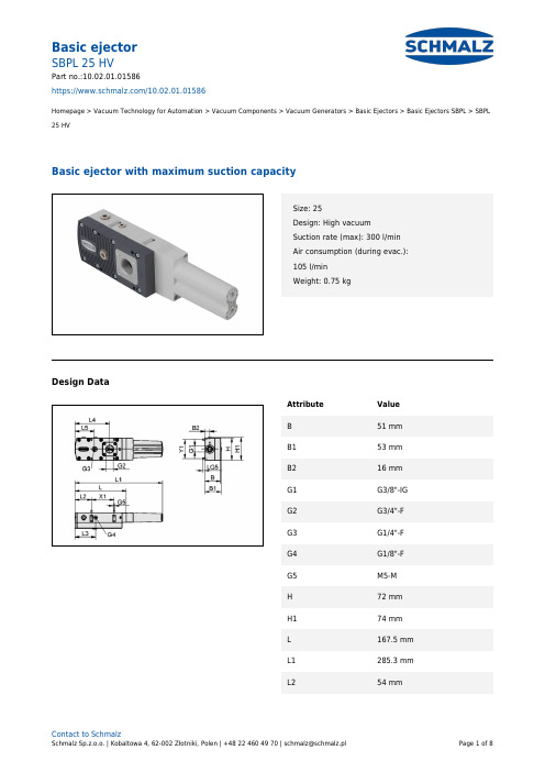
https:///10.02.01.01586Homepage > Vacuum Technology for Automation > Vacuum Components > Vacuum Generators > Basic Ejectors > Basic Ejectors SBPL > SBPL 25 HVBasic ejector with maximum suction capacitySize: 25Design: High vacuumSuction rate (max): 300 l/minAir consumption (during evac.):105 l/minWeight: 0.75 kgDesign DataAttribute ValueB51 mmB153 mmB216 mmG1G3/8"-IGG2G3/4"-FG3G1/4"-FG4G1/8"-FG5M5-MH72 mmH174 mmL167.5 mmL1285.3 mmL254 mmhttps:///10.02.01.01586Attribute ValueL367 mmL4113 mmL564 mmLG58.5 mmX173.5 mmY162 mmTechnical DataAttribute ValueSize25Degree of evacuation90 %Max. vacuum900 mbar Suction rate (real)300 l/min Suction rate (theo)330 l/min Suction rate (real)18 m³/h Suction rate (theo)19.8 m³/h Air consumption suction105 l/minAir consumption suction 6.5 m³/h Sound level free65 dB(A) Sound level suction55 dB(A) Pressure range (operating pressure) 2.0 ... 6.0 bar Pressure range (operating pressure)29.0...87.0 Recomm. internal hose diameter compressed air 6 mm Recomm. internal hose diameter vacuum20 mm Weight0.75 kghttps:///10.02.01.01586Attribute Value Operating temperature0 ... 60 °C Max. vacuum26.577 inHgSpare PartsSEP HV 3 16 22Part no.10.02.01.01397Multistagenozzle as a cartridgeDesign: High vacuumNumber of stages: 3Nozzle size: 1,6 mmHole diameter: 22 mmDegree of evacuation: 90 %Pressure range (operating pressure):2.0 ... 6.0 barPressure optimal: 4 barSuction rate (max): 308.8 l/minAir consumption (during evac.):103 l/minERS-SET SEP-22 6xRUE-KLAPPart no.10.02.01.01450Set of spare partsfor: Ejector moduleSize: 22contains: 6x Non-return flap Accessorieshttps:///10.02.01.01586VFT G1/2-IG 80Part no.10.07.01.00125Vacuum cup filter with transparent housing andreplaceable filterConnection: G1/2"-FShape: Long filter insertNominal flow rate: 18 m³/hFilter pore size: 80 µmVFT G1/2-IG 100Part no.10.07.01.00126Vacuum cup filter with transparent housing andreplaceable filterConnection: G1/2"-FShape: Long filter insertNominal flow rate: 19.2 m³/hFilter pore size: 100 µmVAM 40 V DRPart no.10.07.02.00035Vacuum gauge (manometer) for analogue measurementand monitoring of the vacuumExternal diameter D: 40 mmMeasuring range: -1.00 ... 0.00 barShape: With sealing ringVacuum connection: G1/8"-Mhttps:///10.02.01.01586VAM-D 30x30 VP10 G1/8-AGPart no.10.07.02.00055Vacuum gauge (manometer) for measurement andmonitoring of the vacuumLength L: 30 mmWidth B: 30 mmMeasuring range: -1.0 ... 10.0 barVacuum connection: G1/8"-MVSi V M12-4Part no.10.06.02.00570Vacuum and pressure switch with two digital outputsignals and IO-Link functionMeasuring range: -1...0 barElectrical connection:Male connect M12, 4 polIndication: LEDProtection: IP 65VSi V D M12-4Part no.10.06.02.00580Vacuum and pressure switch with two digital outputsignals and IO-Link functionMeasuring range: -1...0 barType: with displayElectrical connection:Male connect M12, 4 polIndication: 2xLEDProtection: IP 65https:///10.02.01.01586BEF-WIN 72x25x77 SBPLPart no.10.02.01.01705Mouting bracket (inst.)Length L: 72 mmWidth B: 25 mmHeight H: 77 mmfor: Basic ejectorsEMV 3 24V-DC 2/2 NC K-2PPart no.10.05.01.00366Solenoid valve EMV for direct control of compressed airNominal size: 3 mmVoltage: 24V - DCFunction: 2/2-way valveControl: Normally closedConnecting thread: G1/4"-Mcontains: Cable 2Cable length: 3 mST 20 AL-ELPart no.10.02.01.01679Hose sleeveInternal hose diameter: 20 mmMaterial: AluminiumSurface: anodizedhttps:///10.02.01.01586VSL 27-20 PU-DS-ASPart no.10.07.09.00047Hose for vacuum and compressed-air systemsExternal diameter D: 27 mmInternal diameter d: 20 mmLength (max): 20 mMaterial: PU, wire spiral, antistatInstallation radius (min): 17 mmColour: TransparentPressure range (operating pressure):-1.00 ... 4.72 barAmbient temperature: -40 ... 90 °CSET SBPL 75/100Part no.10.02.01.01685Retrofit kitfor: Basic ejectorsSize: 75/100VRS-ST 15x101.7 SBPLPart no.10.02.01.01687Sealing plug - pre-assemblyExternal diameter D: 15 mmLength L: 101.7 mmfor: Basic ejectorshttps:///10.02.01.01586Part no.10.02.01.01450Set of spare partsfor: Ejector moduleSize: 22contains: 6x Non-return flap。
真空知识及真空产品介绍
分路器
真空管
接头元件
2020/6/26
创新的真空自动化
42
汽车行业
2020/6/26
创新的真空自动化
43
木工行业
2020/6/26
创新的真空自动化
44
注塑行业
2020/6/26
创新的真空自动化
45
包装行业
2020/6/26
创新的真空自动化
46
CD光盘行业
2020/6/26
创新的真空自动化
创新的真空自动化
22
新型吸盘–磁铁吸盘SGM
2020/6/26
创新的真空自动化
23
新型吸盘–磁铁吸盘SGM
2020/6/26
创新的真空自动化
24
新型吸盘–磁铁吸盘SGM
磁铁吸盘SGM应用录像
2020/6/26
创新的真空自动化
25
安装部件
弹簧缓冲支杆
2020/6/26
铝型材
固定夹
挠性接头
创新的真空自动化
真空基础知识 及
Schmalz真空元件产品
真空基础知识
什么是真空 / 压力 ?
• 根据 DIN 28400标准: „真空是空气分子密度小于地面大气分子密度的一种状态。 当气体
的压力小于大气压力时可称之为真空。“
• 这意味着,我们可以利用周边压力与绝对压力之间压力 差。
•然而,这个压力差并不是在所有地方 都相同的。
2020/6/26
创新的真空自动化
14
吸盘概览
SAF - 扁平吸盘 (NBR), 圆形 SAB - 波纹形吸盘 (NBR),1.5 折,圆形 SAOF - 扁平吸盘(NBR), 椭圆形 SAOB - 波纹形吸盘(NBR),1.5折,圆形
施迈茨SXMP真空发生器

18
整改项目汇总
备注:在用SXMP代替SMART PUMP时请进行如下设定
通过上述两个步骤就可以设定外部吹气的时间,不再需要改变机械手的程序中加时间
延迟了. 只有当选择E-T的情况下,tbl功能才会被激活。只有当选择了E-T外部吹气的 情况下才可以设定吹气时间tbl
E-T功能的简要说明:
依靠外部时间控制吹气blow-off-time-dependent( E-T)
运行时间
状态指示:
S`` 绿色闪动- 系统有微小泄漏
S``` 红色闪动- 警告,系统有较大泄漏 S```` 常红 系统出现故障,必须停机检修
14
整改项目汇总
灯光指示对应的真空设定值
灯光状态 绿灯常亮
真空度对应范围 当前真空值V 〉H1
绿灯闪烁
红灯闪烁 红灯常亮
H1 〉当前真空值V 〉H1-h1
重要
2
整改项目汇总
真空传感器的基本调节: 概念点:真空度---真空的压力值(负数)
HYS模式---迟滞模式(默认模式) 真空传感器的设定主要有两方面作用: 1)通道1,是为了给真空发生器吸气电磁阀一个信号。可以根据通道1的 (H1\H1-h1)设定值来调整真空发生器在何时产生真空或在何时停止产生真空,从 而达到一个节气的目的。 2)通道2,是为了给机械手一个信号(H2/H2-h2)表示机械手已经抓紧了 工件,这个时候机械手可以运动了。但是在GMG的机械手上暂时未使用到该通道。
。输入正确的 PIN. • 用 UP 或 DOWN 去选择 SEt. • 按 ENTER 进入 • 用 UP 或 DOWN 去选择Pn2 . • 按 ENTER 进入. • 用 UP 或 DOWN设定第一个PIN码。 • 按 ENTER 确认 • 用同样的方法设定第二和第三个PIN码。 • 按住ENTER最少3秒用于存储新的PIN码
真空单元 ZX 系列 NO. ZX-OM00201 使用说明书
NO. ZX-OM00201使用说明书真空单元ZX系列目录页码1. 概述 22. 规格 22.1真空发生器的性能 22.2 作动规格 23. 使用建议3.1 关于使用流体的质量 23.2 关于真空发生器系统的配管方法 23.3 关于真空泵系统的配管方法 33.4 关于吸盘的个数 33.5 电磁阀的电压 33.6 压力开关的电压 33.7 关于使用环境 34. 操作 35. 关于维护・检查 36. 外观及回路图6.1真空系统 46.2 泵系统 57. 型号表示 6.71. 概述ZX系列是通过吸附来搬运电子零件、小型精密零件的装置。
它由供给的压缩空气、进行真空的切换和破坏的电磁阀单元、进行工件吸附确认的真空用压力开关、过滤灰尘的过滤器以及真空发生器构成的。
2.规格2.1 真空发生器的性能2.2 作动规格3. 使用建议3.1 关于使用流体的质量供气侧过滤器最合适的过滤精度为5μm。
(供气侧请使用不含油雾的清洁型过滤器)。
3.2 关于真空发生器系统的配管方法1)请将使用的空气配管充分吹净后再安装。
2)空气压供给(PV)通口(M5)请供给0.3~0.6MPa的压缩空气。
3)真空(V)通口(M5)请连接真空吸盘。
3.3 关于真空泵系统的配管方法1)请将使用的空气配管充分吹净后再安装。
2)真空压供给(PV)通口(M5)请供给真空压力。
3)先导压力供给(PS)通口(M3)请供给0.3~0.6MPa的压缩空气。
4)真空(V)通口(M5)请连接真空吸盘。
3.4 关于吸盘的个数原则上1个真空(V)通口安装1个吸盘。
3.5 电磁阀的电压请按照各产品的规格电压连接电源。
请注意DC规格的电磁阀有极性。
(红:正极,黑:负极)3.6 压力开关的电压压力开关与产品同捆输出。
请参考压力开关的使用说明书。
3.7 关于使用环境请避免在含有海水的飞沫、水、水蒸气的环境中使用。
并且,由于过滤器壳体材质为聚碳酸酯,所以请避免在使用或含有信钠水、四氯化碳、氯仿、醋酸、酯、苯胺、环已烷、三氯乙烯硫酸、乳酸等化学药品的环境中使用。
Schmalz vs-v-d-pnp真空发生器说明书中文
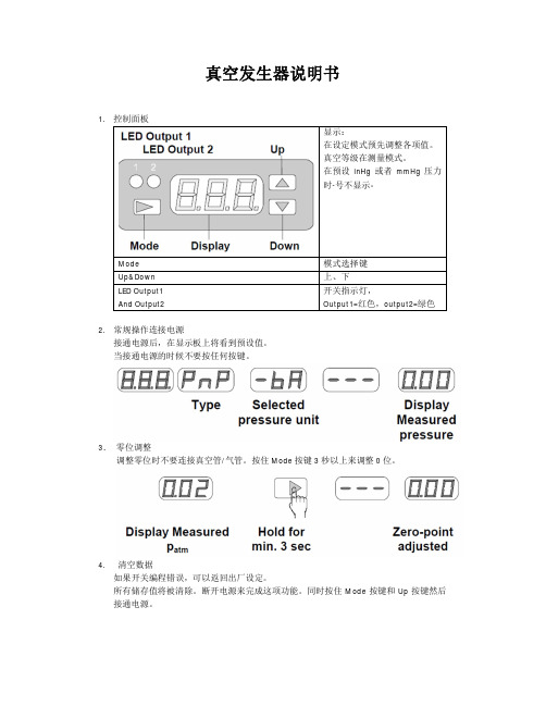
真空发生器说明书1.控制面板显示:在设定模式预先调整各项值。
真空等级在测量模式。
在预设inHg 或者mmHg 压力时-号不显示。
Mode 模式选择键Up&Down 上、下LED Output1And Output2开关指示灯,Output1=红色,output2=绿色2.常规操作连接电源接通电源后,在显示板上将看到预设值。
当接通电源的时候不要按任何按键。
3.零位调整调整零位时不要连接真空管/气管。
按住Mode 按键3秒以上来调整0位。
4.清空数据如果开关编程错误,可以返回出厂设定。
所有储存值将被清除。
断开电源来完成这项功能。
同时按住Mode 按键和Up 按键然后接通电源。
接通电源后,会显示CLA。
当松开按键后会分别显示-bA,bA。
当按Mode一次时,选择的压力将会被确认及储存。
要调整另外一种压力时见6.35.出厂设定真空开关各项出厂值如下单位输出1输出2Bar HYS,N.O.HYS,N.O.这些设定是可更改的(可被编辑)下列章节将介绍如何编辑。
内置了一个最少可保存10年的电可擦只读存储器。
数据最少可在写入10000次。
N.O=常开,N.C.=常闭,HYS=操作模式“迟滞模式”;工作模式的初始值表格见第8节。
6.设定输出配置(常开或常闭)和压力单位(如:bar)要设定输出模式及压力单位,按住并保持Mode键,然后按Up键。
显示屏将在’’ou 1’’和’’n.o’’交替变换显示。
6.1为Output1选择 N.O.或者N.C.按Up或者Down来更改设定。
按Mode键储存。
接下来开关将显示Output2的设定选择。
将会在’’ou 2’’和’’n.o’’交替变换显示。
6.2为Output2选择 N.O.或者N.C.按Up或者Down来更改设定。
按Mode键储存。
接下来将显示压力单位的选择。
6.3调整压力单位按Up或者Down来更改设定。
按Mode键储存。
型号VS-V-D可能的单位为型号VS-P10-D可能的单位为7.调整工作模式7.1调整output1例如:开关VS-V-D,output1有“迟滞模式”开关点:-0,6 bar迟滞:0,15bar更多信息参考第8节。
真空发生器设置
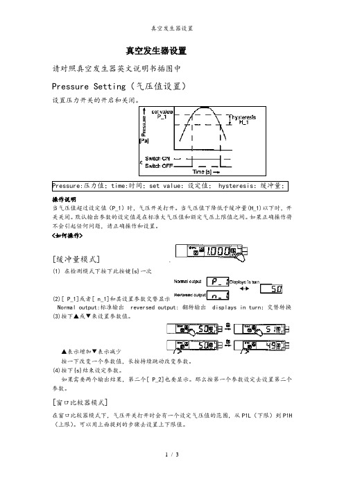
真空发生器设置请对照真空发生器英文说明书插图中Pressure Setting(气压值设置)设置压力开关的开启和关闭。
操作说明当气压值超过设定值(P_1)时,气压开关打开。
当气压值下降低于缓冲量(H_1)以下时,开关关闭。
默认输出参数的设定值是在标准大气压值和额定气压上限值之间。
如果正确操作将不会引起任何问题,请正确操作和设置。
<如何操作>[缓冲量模式](1) 在检测模式下按下此按键{s}一次(2)[ P_1]或者[ n_1]和其设置参数交替显示Normal output:标准输出 reversed output: 翻转输出 displays in turn:交替转换(3)按下▲或▼来设置参数值。
▲表示增加▼表示减少按一下改变一个参数值,长按持续跳动改变参数。
(4)按下{s}结束设定参数。
如果需要两个输出结果,第二个[ P_2]也要显示。
那么按第一个参数设定去设置第二个参数。
[窗口比较器模式]在窗口比较器模式下,气压开关打开时会有一个设定气压值的范围,从P1L(下限)到P1H (上限)。
可以用上面提到的步骤去设置上下限值。
Setting of Function (功能设置)■默认设置以下参数为出场设置,如果设置复合,请保持。
如想改变,登入SMC官网获得详细信息或联系我们。
[ F1]输出1设置F2设定与F1设定一样其他设置■检测模式检测模式是气压实时检测,显示,功能开关打开的一种状态,这也是最基本的模式,而其他模式是用来改变参数或者功能参数。
通电→显示标准值→显示单元模块→显示值→显示压力范围→测量模式■功能选着模式检测模式下,按下{S}键2秒或更长,显示[F0],改变选定功能设定值。
在功能选择模式按下{S}键2秒或更长返回检测模式。
Measurement mode:测量模式 press the button for 2s or longer 长按2秒或以上function selection mode :功能选择模式 setting functions:功能设置Trouble shooting (故障点及处理方法)■错误指示功能此功能是显示错误点和问题点发生的内容。
Festo VZWD-L-M22C-M-N14-20-V-3AP4-15商品说明书
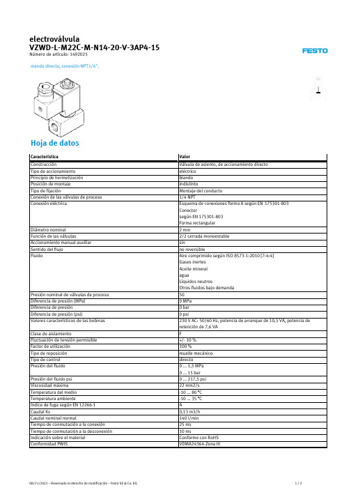
Número de artículo: 1492025
mando directo, conexión NPT1/4".
Hoja de datos
Característica Construcción Tipo de accionamiento Principio de hermetización Posición de montaje Tipo de fijación Conexión de las válvulas de proceso Conexión eléctrica
Valor
latón CW614N FPM 350 g según la normativa UE de baja tensión Según la normativa sobre utillaje eléctrico del Reino Unido IP65 1 - riesgo de corrosión bajo
1/2
Característica
Material de la carcasa Número del material cuerpo Material de las juntas Peso del producto Marca CE (ver declaración de conformidad) Marcado UKCA (véase la declaración de conformidad) Tipo de protección Clase de resistencia a la corrosión KBK
08/11/2023 – Reservado el derecho de modificación – Festo SE & Conominal Función de las válvulas Accionamiento manual auxiliar Sentido del flujo Fluido
华明真空SHZV
SHZV油浸式真空熄弧有载分接开关HM0.460.3901说 明1.在使用本产品前仔细阅读本说明书。
2. SHZV有载开关维护应有经过培训的专业人员进行。
3. 随着产品的不断改进提升,华明对提供的技术数据、使用说明书与技术数据保留更改权利。
4. 对于技术数据超出本说明书规范的产品和特殊的使用场合,可以与华明沟通,确定特殊设计方案,进行客户化定制。
目 录1. 概述 (1)2. 分接开关的结构(常规) (7)3. 分接开关的结构(条板式选择器) (10)4. 切换开关工作原理 (11)5. SHZV有载分接开关在变压器上安装 (12)6. 运行监视 (18)7. 检修周期 (18)8. 成套范围 (18)9. 附图 (19)迄今为止,国内外使用的油浸式有载分接开关,其油室内的油,既是分接开关的绝缘介质,又是切换过程中主通断触头及过渡触头电弧熄灭的介质,同时兼作机械传动部分的润滑剂和触头与导电部件的冷却介质,因此也可以称作油中熄弧的有载分接开关。
这种分接开关在运行中油的碳化是不可避免的,随着操作次数的增加,油中的碳化物不断增多。
油中熄弧的有载分接开关使用在除了中性点调压之外的其它部位上时,或者在220kV 及以上的电力变压器上时,不得不添加在线滤油装置,以保证油的绝缘强度以及减少油中的碳粒。
当它使用在电解、冶炼等其它变压器上时,由于加工工艺上的需要,操作相当频繁且又都是在满负荷或过负荷下进行的,这样电弧触头的烧损、油的碳化都很快,同时也加剧了机械磨损。
因此不得不经常的换油或滤油和更换电弧触头,用频繁的维护、检修来保证开关的可靠运行,有的甚至在变压器的使用寿命内还得更换开关,维持正常使用的成本相当昂贵。
如何从设计上来改变这种现象,使得绝缘油仅仅是开关的绝缘介质,在长时间的运行中始终保证油的良好的绝缘性能及良好的机械润滑性能。
这样不管分接开关使用在哪种场合下,都只需要很少的、很简单的维护检修就能达到长期使用的可靠性,使得运行成本降到最低。
- 1、下载文档前请自行甄别文档内容的完整性,平台不提供额外的编辑、内容补充、找答案等附加服务。
- 2、"仅部分预览"的文档,不可在线预览部分如存在完整性等问题,可反馈申请退款(可完整预览的文档不适用该条件!)。
- 3、如文档侵犯您的权益,请联系客服反馈,我们会尽快为您处理(人工客服工作时间:9:00-18:30)。
真空发生器说明书
1.控制面板
显示:
在设定模式预先调整各项值。
真空等级在测量模式。
在预设inHg 或者mmHg 压力时-号不显示。
Mode 模式选择键Up&Down 上、下
LED Output1And Output2
开关指示灯,
Output1=红色,output2=绿色
2.常规操作连接电源
接通电源后,在显示板上将看到预设值。
当接通电源的时候不要按任何按键。
3.零位调整
调整零位时不要连接真空管/气管。
按住Mode 按键3秒以上来调整0位。
4.
清空数据
如果开关编程错误,可以返回出厂设定。
所有储存值将被清除。
断开电源来完成这项功能。
同时按住Mode 按键和Up 按键然后接通电源。
接通电源后,会显示CLA。
当松开按键后会分别显示-bA,bA。
当按Mode一次时,选择的压力将会被确认及储存。
要调整另外一种压力时见6.3
5.出厂设定
真空开关各项出厂值如下
单位输出1输出2
Bar HYS,N.O.HYS,N.O.
这些设定是可更改的(可被编辑)
下列章节将介绍如何编辑。
内置了一个最少可保存10年的电可擦只读存储器。
数据最少可在写入10000次。
N.O=常开,N.C.=常闭,
HYS=操作模式“迟滞模式”;
工作模式的初始值表格见第8节。
6.设定输出配置(常开或常闭)和压力单位(如:bar)
要设定输出模式及压力单位,按住并保持Mode键,然后按Up键。
显示屏将在’’ou 1’’和’’n.o’’交替变换显示。
6.1为Output1选择 N.O.或者N.C.
按Up或者Down来更改设定。
按Mode键储存。
接下来开关将显示Output2的设定选择。
将会在’’ou 2’’和’’n.o’’交替变换显示。
6.2为Output2选择 N.O.或者N.C.
按Up或者Down来更改设定。
按Mode键储存。
接下来将显示压力单位的选择。
6.3调整压力单位
按Up或者Down来更改设定。
按Mode键储存。
型号VS-V-D可能的单位为
型号VS-P10-D可能的单位为
7.调整工作模式
7.1调整output1
例如:开关VS-V-D,output1有“迟滞模式”
开关点:-0,6 bar
迟滞:0,15bar
更多信息参考第8节。
调整工作模式
选择output1,按mode按键2次
2秒后将会交替显示预设的工作模式和ou 1;
按Up或者Down键,直到需要的开关模式“迟滞”显示出来。
按一次Mode键储存。
设定开关点和迟滞值
要选择output1的开关点按Mode键1次
2秒后H-1和预设值将交替显示。
按up/down调至所需数值。
按一次Mode键储存。
现在开关将显示迟滞。
“h1”和预设值将交替显示。
按up/down调至所需数值。
按一次Mode键储存。
7.2调节output2
例如:开关VS-V-D,output2带有区间比较模式
开关点将在-0,57—0.83(下限A=-0,57,上限b=-0,83)更多信息请看8节;
调节工作模式
按Mode键4次
2秒后将在“ou 2”“HYS”间切换显示
按Up/down直到区间比较模式“CnP”显示。
按一次Mode键储存。
调整上下限
按Mode键3次选择Output2的下限
2秒后将在“A-2”及预设值切换显示。
按Up/down直到所需设定值显示。
按一次Mode键储存。
接下来开关将显示调整的上限值。
显示将在“b-2”和预设值间切换。
按Up/down直到所需设定值显示。
按一次Mode键储存。
8.outputs工作模式
Outputs可以在两种模式下工作。
两种模式均可独立设定值。
工作模式描述如下。
8.1迟滞模式
设置为开关点H和迟滞h.
例如:VS-V-D
H=-0.60 bar
H=0.15 bar
N.O.(Normally Open)
在0bar,是数字输出关闭。
当真空度增加至开关点H设定值时,输出开。
只要真空值比-0.45bar(=0.6bar-0.15bar)高时,输出将保持。
当真空值减少或超过-0.45时输出信号关闭。
当配置为N.C.时,输出信号将相反。
出厂设定:Output1&2在迟滞模式的预设值
8.2区间比较模式
设定下限值A和上限值b
例如:VS-V-D
A=-0.45 bar
B=-0.60 bar
N.O.(Normally Open)
在0bar时,数字输出关闭。
当真空值增加到下限A,输出开,当真空值在A与b之间时,输出信号将保持。
当真空值达到比上限更高时将关闭。
当配置为N.C.时,输出信号相反。
出厂设定:Output1&2在区间比较模式的预设值
9.峰值及谷值显示
当开关接通电源后,内置存储器将储存正常工作时的峰值及谷值。
按Up键显示峰值
按Down键显示谷值
10.旋转显示
当安装位置旋转时,显示可以旋转。
当连接电源时,同时按住Up和Down键
注意小数点的显示方向将会改变。
功能键将仍旧保持其原有功能。
11.锁定设定值
11.1标准版本
同时按住Mode键和Down键,所有按键被锁定。
屏幕上将显示LoC
再同样一次操作可以解锁。
显示UnC
11.2PIN码版本
该锁将阻止无授权人员更改设定值。
编程者可设定一个3位的密码来加密。
激活密码锁
按住并保持Mode键再按Down键
再按上下来更改数字
按Mode储存数字。
下一个密码将闪烁,依次设定其余密码。
设定完成后LoC将显示并被激活。
使密码失效
按住并保持Mode键再按Down键
000将显示,输入正确的密码将会解锁,错误的将会继续锁定显示LoC。
如果密码设定后,若不慎遗失,需返厂解锁。
12.错误信息。