盘式制动器外文文献
制动器相关的外文文献

hub and rotor assemblyA ventilated rotor is cast with a weblike construction between two friction surfaces.The webs radiate out from the center of the rotor, much like vanes or fins in a fan . As the rotor turns,air is drawn into the rotor at its center , flows between the friction surfaces, and is discharged along the outer edge . this cools the rotor . which drastically reduces the chances of brake fade , even during multiple hard stops .a splash shield protects the rotor and pads from road splashes and dirt . it is also shaped to channel the flow of air over the exposed rotor surfaces . as long as the car is moving , this flow of air helps to cool the rotor . the splash shield cannot be removed unless the rotor and caliper are first removed . replacement of the splash shield is necessary only when it has been damaged or when the spindle is replaced .caliper assemblya brake caliper converts hydraulic pressure into mechanical force . the caliper housing is usually a one-piece construction of cast iron or aluminum and has an inspection hole in the top to allow for lining wear inspection . the housing contains the cylinder bore . in the cylinder bore is a groove that seats a square-cut seal . this groove is tapered toward the bottom of the bore to increase the compression on the edge of the bore to increase the compression on the edge of the seal that is nearest hydraulic pressure . the top of the cylinder bore is also grooved as a seat for the dust boot . a fluid inlet hole is machined into the bottom of the cylinder bore and a bleeder valve is located near the top of the casting .a caliper can contain one , two , or four cylinder bores and pistons that provide uniform pressure distribution against the brake's friction pads . the pistons are relatively large in diameter and short in stroke to provide high pressure on the friction pad assemblies with a minimum of fluid displacement .basically the hydraulics of disc brakes are the same as for drum brakes , in that master cylinder piston forces the brake fluid into the wheel cylinders and against the wheel pistons .the disc brake piston is made of steel , aluminum , or fiberglass-reinforced phenolic resin . steel pistons are usually nickel-chrome plated for improved durability and smoothness . the top of the pistons is grooved to accept the dust boot that seats in a groove at the top of the cylinder bore and also in a groove in the piston . the dust boot prevents moisture and road contamination from entering the bore .a piston hydraulic seal prevents fluid leakage between the cylinder bore wall and the piston . this rubber sealing ring also acts as a retracting mechanism for the piston when hydraulic pressure is released , causing the piston to return in its bore (Figure 46-3). when hydraulic pressure is diminished , the seal functions as a return spring to retract the piston .In addition,as the disc brake pads wear , the seal allows the piston to move farther out to adjust automatically for the wear , without allowing fluid to leak.Since the brake pads need to retract only slightly after they have been applied,the piston moves back only slightly into its bore.The additional brake fluid in the caliper bore keeps the piston out and ready to clamp the surface of the rotor.fixed caliper disc brakesfixed caliper disc brakes have a caliper assembly that is bolted in a fixed position and does not move when the brakes are applied . the pistons in both sides of the caliper come inward to force the pads against the rotor (Figure 46-4).floating caliper disc brakesa typical floating caliper disc brake is a one-piece casting that has one hydraulic cylinder and a single piston . the caliper is attached to the spindle anchor plate with two threaded locating pins .a Teflon sleeve separates the caliper housing from each pin and the caliper slides back and forth on the pins as the brakes are actuated . when the brakes are applied , hydraulic pressure builds in the cylinder behind the piston and seal . because hydraulic pressure exerts equal force in all directions , the piston moves evenly out of its bore .the piston presses the inboard pad against the rotor . as the pad contacts the revolving rotor , greater resistance to outward movement is increased , forcing pressure to push the caliper away from the piston , this action forces the outboard pad against the rotor (figure 46-5). however , both pads are applied with equal pressure .sliding caliper disc brakesWith a sliding caliper assembly , the caliper slides or moves sideways when the brakes are applied.As mentioned previously ,in operation,these brakes are almost identical to the floating type.But unlike the floating caliper ,the sliding caliper does not float on pins or bolts attached to the anchor plate (Figure 46-6).It has angular machined surfaces at each end that slide in mating machined surfaces on the anchor plate.This is where the caliper slides back and forth .Some sliding calipers use a support key to locate and support the caliper in the anchor plate . the caliper support key is inserted between the caliper and the anchor plate . a worn support key may cause tapered brake pad wear . always inspect the support keys when replacing brake pads . also make sure they are lubricated when reassembling the unit .brake pad assemblybrake pads are metal plates with the linings either riveted or bonded to them . pads are placed at each side of the caliper and straddle the rotor . the inner brake pad , which is positioned against the piston , is not inter changeable with the outer brake pad . the linings are made of semimetallic or other nonasbestos material (Figure 46-7).DISC PAD WEAR SENSORSSome brake shoe pads have wear sensing indicators.The three most common design weal sensors are audible,visual,and tactile .Audible sensors are thin,spring steel tabs that are riveted to or installed onto the edge of the pad's backing plate and are bent to contact the rotor when the lining wears down to a point that replacement is necessary .At that point,the sensor causes a high-pitched squeal whenever the wheel is turning,except when the brakes are applied,then the noise goes away.The noise gives a warning to the driver that brake service is needed and perhaps saves the rotor from destruction (Figure 46-8). the tab is generally installed toward the rear of the wheel .visual sensors inform the driver of the need for new linings . this method employs electrical contacts recessed in the pads that touch the rotor when the linings are worn out . this completes a circuit and turns on a dashboard warning light . this system is found mostly on imports .tactile sensors create pedal pulsation as the sensor on the rotor face contracts the sensor attached to the lower portion of the disc pad .cautionas disc brake pad linings wear thin , more brake fluid is needed in the system.Customer careExcessive heat liquefies the resin binder that holds the brake pad material together . once liquefied , the binder rises to the surface of the pad to form a glaze .A glazed pad may cause squealing because more heat is needed to achieve an amount of friction equal to a pad in good condition.One common cause of pad glazing is the improper break-in of the pads.Remember to inform customers that unnecessary hard braking during the first 200 miles(320km)of a pad’s life can generate enough heat to glaze the pads and ruin the quality of the work just performed .There are Pads now available that require no break-in time . Rear Disc / Drum (Auxiliary Drum) Parking BrakeThe rear disc / drum or auxiliary drum parking brake arrangement is found on some vehicles . on these brakes , the inside of each rear wheel hub and rotor assembly is used as the parking brake drum(Figure 46—9) . The auxiliary drum brake is a smaller version of a drum brake and is serviced 1ike any other drum brake .Rear Disc Parking BrakesInstead of using an auxiliary drum and shoes to hold the vehicle when parked,these brakes have a mechanism that forces the pads against the rotor mechanically.One method for doing this is the ball-and-ramp arrangement.Another method that is found on many vehicles has a threaded,spring-loaded pushrod (Figure 46-10).As the parking brakes are applied ,a mechanism rotates or unscrews the pushrod ,which in turn pushes the piston out .Other types of actuating systems for rear disc brakes include the use of a variety of cams.DISC BRAKE DIAGNOSISMany problems that are experienced on vehicles with disc brakes are the same ones that are evident with drum brake systems .There are some problems that occur only with disc brakes.Before covering the typical complaints , it is important to remind you to get as much information as possible about the complaint from the customer.Then road test the vehicle to verify the complaint.A complete inspection of the rotor , caliper , and pads(Figure 46-11) should be done anytime you are working on the brakes.What follows is a brief discussion of common complaints and their typical causes.The red warning light indicates there is a problem in the regular brake system , such as low brake fluid levels or that the parking brake is on . a low fluid light may be present in addition to the red brake warning light . whenever the fluid is low , you should suspect a leak or very worn brake pads .The yellow or amber brake warning light is tied into the antilock brake system . this light turns on for two reason : the ABS system is performing a self-text or there is a fault in the ABS system .A blue warning light lets the driver know the wheels are slipping because of poor road conditions . more discussion on the amber and blue lights is given in the next chapter of this book .Pulsating pedalCustomers will feel a vibration or pulsation in the brake pedal when the brakes are applied if a brake rotor is warped . if this symptom exists , check the rotors for runout and parallelism . a warped rotor should be replaced and is often caused by improper tightening of the wheel lug nuts . in fact , uneven lug nut torque can cause a pulsating brake pedal . you should be aware that pedal pulsation is normal on vehicles with ABS when the antilock brake system is working . Spongy PedalWith a spongy pedal , the customer will probably feel the need to pump the brake pedal to getgood stopping ability . the complaint may also be described as a soft pedal . this problem is caused by air in the hydraulic system . Although bleeding the system may remove the air,you should always question how the air got in there .Check for leaks and for proper master cylinder operation.Hard PedalThe driver’s complaint of a hard pedal normally indicates a problem with the power brake booster . However it can also be caused by a restricted brake line or hose . Carefully check the lines and hoses for damage . Feel the brake hoses . if they seem to have lost their rigidity , the hose may have collapsed on the inside and this is causing the restriction . Restrictions can also be caused by frozen caliper or wheel cylinder pistons.Dragging BrakesDragging brake make the vehicle feel as if it has lost or is losing power as it drives down the road . the problem also wastes a lot of fuel and generates destructive amounts of heat that can cause serious brake damage and brake failure . while trying to find the cause of this problem , check the parking brake first . make sure it is off . check the rear wheels to make sure the parking brakes are released when they should be . if the problem is not in the parking brakes , check for sticky or seized pistons at the calipers and wheel cylinders .Grabbing BrakesWhen the brakes seem to be overly sensitive to pedal pressure , they are grabbing . normally this problem is caused by contaminated brake linings . if the lings are covered or saturated with oil , find the source of the oil and repair it . then replace the pads and refinish or replace the rotor .NoiseIf the customer’s complaint is noisy brakes , v erify during the road test that the problem is in the brakes . if the noise is caused by the brakes , pay attention to the type of noise and let that lead to the source of the problem . remember , some brake pads have wear sensors that are designed to make a high-pitched squeal when the pads are worn . other causes could be the rotor rubbing against the splash shield or that something has become wedged between the rotor and another part of the vehicle . noise may also be caused by failure to install all of the hardware when placing a caliper or brake pads in service .PullingWhen a vehicle drifts or pulls to one side while cruising or when braking , the cause could be in the brake system or in the steering and suspension system . check the inflation of the tires , the tires’ tread condition , and verify that the tires on each axle are the same size . check the operation of the brakes . if only one front wheel is actually doing the braking , the vehicle will seem to stumble or pivot on that one wheel . if no problems are found in the brake system , suspect an alignment or suspension problem .SERVICE PRECAUTIONSThe following general service precautions apply to all disc brake systems and should always be followed :1. Be sure the vehicle is properly centered and secured on stands or a hoist .2. If the vehicle has antilock brakes , depressurize the system according to the procedures given in the service manual .3. Disconnect the battery ground cable .4. Before any service is performed , carefully check the following :■tires for excessive wear or improper inflation■wheels for bent or warped rims■wheel bearings for looseness or wear■suspension components to see if they are worn or broken■brake fluid level■master cylinder , brake lines or hoses , and each wheel for leaks5. During servicing , grease , oil , brake fluid , or any other foreign material must be kept ff the brake linings , caliper , surfaces of the disc , and external surfaces of the hub . handle the brake disc and caliper in such a way as to avoid deformation of the disc and nicking or scratching of the brake linings .6. when a hydraulic hose is disconnected , plug it to prevent any foreign material from entering .7. never permit the caliper assembly to hang with its weight on the brake hose . support it on the suspension or hang it by a piece of wire .8. inspect the caliper for leaks . if leakage is present , the caliper must be over hauled .9. when using compressed air to remove caliper pistons , avoid high pressures . a safe pressure to use is 30 psi (207 kPa).10. clean the brake components in either denatured alcohol or clean brake fluid . do not use mineral-based cleaning solvent such as gasoline , kerosene , carbon tetrachloride , acetone , or paint thinner to clean the caliper . it causes rubber parts to become soft and swollen in an extremely short time .11. lubricate any moving member such as the caliper housing or mounting bracket to assure a free-moving action . use only recommended lubricant .12. before the brake pads are installed , apply a disc brake noise suppressor to the back of the pads to prevent brake squeal . for best results , follow the directions on the container .13. obtain a firm brake pedal after servicing the brakes and before moving the vehicle . be sure to road test the vehicle .14. always torque the lug nuts when installing a wheel on a vehicle with disc brakes . never use an impact gun to tighten the lug nuts . warpage of the rotor could result if an impact gun is used . Before beginning brake work , remove about two-thirds of the brake fluid from the master cylinder’s reservoir . if this is not done , the fluid could overflow and spill when the pistons ar e forced back into the caliper bore , possibly damaging the painted surfaces . replace the cover . discard old brake fluid .Another common procedure (and perhaps a better way) is to open the caliper bleeder screw and run a hose down to a container to catch the fluid that is expelled when the piston is forced back into its bore . this also makes it easier to move the piston .If the bleeder screws are frozen tight with corrosion , it is sometimes possible to free them using a propane torch and penetrating oil . of course , the caliper has to be removed from the car , taken to a bench and worked on there.If the bleeder screws cannot be loosened,they can be drilled out and the caliper retapped for an insert , orthe caliper can be replaced with a new or rebuilt unit . the bleeder screw should be removed when doing an overhaul .warningWhen using the propane torch to loosen a bleeder screw , use it with extreme care .GENERAL CALIPER INSPECTING AND SERVICINGFrequently , caliper service involves only the removal and installation of the brake pads . however , since the new pads are thicker than the worn-out set they replace , they locate the piston farther back in the bore where dirt and corrosion might cause the seals to leak . for this reason , it is often good practice to carefully inspect the calipers whenever installing new pads . of course , it is also good practice to true-up or replace the rotors when replacing brake pads . When bench working a caliper assembly , use a vise that is equipped with protector jaws . excessive vise pressure causes bore and piston distortion .Caliper RemovalTo be able to replace brake pads , service the rotor , or to replace the caliper , the caliper must be removed . the procedure for doing this will vary according to caliper design . always follow the specific procedures given in a service manual . use the following as an example of these procedures :1. remove the brake fluid from the master cylinder .2. raise the vehicle and remove the wheel and tire assembly .3. on a sliding or floating caliper , install a C-clamp with the solid end of the clamp on the caliper housing and the screw end on the metal portion of the outboard brake pad . tighten the clamp until the piston bottoms in the caliper bore (figure 46-12), then remove the clamp.Bottoming the piston allows room for the brake pad to slide over the ridge of rust that accumulates on the edge of the rotor.4. On threaded-type rear calipers . the piston must be rotated to depress it.This requires a special tool (Figure 46-13).5. Disconnect the brake hose from the caliper and remove the copper gasket or washer and cap the end of the brake hose.If only the brake pads are to be replaced,do not disconnect the brake hose.6. Remove the two mounting brackets to the steering knuckle bolts .Support the caliper when removing the second bolt to prevent the caliper from falling.7. On a sliding caliper , remove the top bolts , retainer clip , and antirattle springs(Figure 46-14) . On a floating caliper , remove the two special pins that hold the caliper to the anchor plate(Figure 46-15) . On a fixed caliper , remove the bolts holding it to the steering knuckle . On all three types , get the caliper off by prying it straight up and lifting it clear of the rotor .Brake Pad RemovalDisc brake linings should be checked periodically or whenever the wheels are removed.Some calipers have inspection holes in the caliper body.If they do not,the brake pads can be visually inspected from the outer ends of the caliper .If you are not sure the pads are worn enough to warrant replacement , measure them at the thinnest part of the pad . compare this measurement to the minimum brake pad lining thickness listed in the vehicle’s service manual , and replace the pads if needed .When a pad on one side of the rotor has worn more than on the other side , the condition is called uneven wear . uneven pad wear of often means the caliper is sticking and not giving equal pressure to both pads . on a sliding caliper , the problem could be caused by poor lubrication of or deformation of the machined sliding areas on the caliper and/or anchor plate . a slightly tapered wear pattern on the pads of certain mode is caused by caliper twist during braking . it is normal if it does not exceed 1/8-inch (3-mm) taper from one end of the pad to the other (figure46-16) .Sliding or floating caliper must always be lifted off the rotor for pad replacement . fixed calipers might have pads that can be replaced by removing the retaining pins or clips instead of having to lift off the entire caliper . brake pads may be held in position by retaining pins , guide pins , or a support key . note the position of the shims , anti-rattle clips , keys , bushings , or pins during disassembly . a typical procedure for replacing brake pads is outlined in Photo Sequence 50 , included in this chapter .If only the pads are going to be replaced , lift the caliper off the rotor and hang it up by a wire . remove the outer pad and inner pad . remove the old sleeves and bushings and install new ones . replace rusty pins on a floating caliper to provide for free movement . transfer shoe retainers , which can be clips or springs , onto the new pads .。
盘式制动器中英文对照外文翻译文献
中英文对照外文翻译文献(文档含英文原文和中文翻译)外文:An Experimental Analysis of Brake Efficiency Using fourFluids in a Disc Brake SystemABSTRACTThe paper studies disc brake failure in Mini-buses using an experimental analysis to test the maximum braking force when different brake fluids such as clean, less dirty, dirty and soapy water solution were used in the braking system. The experimental results clearly showed that the soap solution appears to be the best fluid as far as low viscosity and stability of viscosity with increase in temperature are concerned. However, the soap solution is not compatible with other fluid which makes it difficult to be substitute as a clean brake fluid. The result of the Thepra Universal Brake Testing Equipment used for the braking efficiency test indicated that a pedal brake of 117 kN produce a brake force of 0.96 kN for clean brake fluid, 0.91 kN for the less dirty, 0.85 kN for dirty and 1.44 kN forsoap solution. The value of 1.44 kN which was achieved when the soap solution was used indicated a positive braking force and the indicating that soap solution could be used to produce a high pedal force within a very short time (about 10-30 min) and can therefore be used only in case of emergency. The brake efficiency test indicated that under hot conditions the braking efficiency is reduced and the presence of air in the system renders the braking ineffective because higher pedal force was needed to be able to produce a significant braking force which is noted for causing brake failure.Keywords: Brake fade, brake failure, disc brake, efficiency, pedal force INTRODUCTIONWhen a vehicle is accelerated, energy supplied by the engine causes the vehicle’s speed to increase. Part of this energy is instantly used up in overcoming frictional and tractive resistance but a large amount of it remains stored in the vehicle. According to Heinz (1999) this energy of motion is called the kinetic energy and the existence of kinetic energy is observed when a vehicle is moving and neutral gear is selected. The vehicle does not immediately come to rest; instead it travels for a considerable distance before it becomes stationary. In this case the stored energy is used to drive the vehicle against the resistances that oppose the vehicle’s motion. Relying on these r esistances to slow down a vehicle could cause many problems, so an additional resistance called a brake is needed to convert the kinetic energy to heat energy at a faster rate in order to reduce the speed of the vehicle Mcphee and Johnson (2007). This reduces the speed of the vehicle at a faster rate and brings the vehicle to rest within the shortest possibletime when the brakes are applied.From the point of view of Johnson et al. (2003) most automotive systems in use today utilize front disc brakes, but four-wheel disc systems are also common In disc brakes, the rotor rotates with the wheel and the pads move out to rub the rotor when the brakes are applied. Most disc brakes use floating calipers. The caliper slides in and out as the brakes are applied and released. The piston moves the inside pad out and pushes the outside pad into the rotor by sliding the caliper back toward the rotor.The use of disc brakes to reduce speed or bring the vehicle to rest when in motion cannot be over emphasized if the safety of the occupant is to be guaranteed Heinz (1999). To bring a vehicle to a stop, the disc brakes have to absorb all the energy given to thevehicle by the engine and that due to the momentum of the vehicle. This energy must then be dissipated. In most vehicle disc brakes, the energy is absorbed by friction, converted into heat and the heat dissipated to the surrounding air (Thoms, 1988). As the energy is absorbed, the vehicle is slowed down; in other words, its motion is retarded. The brakes must also pull up the vehicle smoothly and in a straight line to bring the vehicle to a stop position.It is therefore very important that the disc brakes of vehicles operate with the highest efficiency. This couldreduce the rate of accidents due to brake failure so that life and property could be preserved and also to ensure that occupants of these commercial vehicles go about their normal lives without any fear of being involved in an accident. Available crash data in Ghana suggests that about 1,900 persons are killed annually in road traffic crashes (Afukaar et al., 2008) and that more than 40% of the road traffic fatalities are occupants of cars, buses and trucks. Most often than not, some of the road accidents involving commercial vehicles, such as the mini-buses have been attributed to the failure of the disc brakes. The reason for testing the viscosity of these brake fluids, especially that of the soap solution was as a result of the practice of most Ghanaian drivers sometimes using the soapy solution as a substitute to the original brake fluid in the braking system and also using dirty brake fluid which has been used for bleeding purposes. The main objective of this study which is part of a larger work seeks to investigate and establish the reasons for the disc brake failure due to brake fluid also check the efficiency of the four different types of fluids used in the transmission of braking forces. The study looked at the maximum braking force when using clean, less dirty, dirty and soapy water solution in the braking system. It also looked at the braking force when the braking system is with or without servo unit and operating under cold or hot condition with air or without air in the braking systemDISC BRAKESThe disc brake consists of an exposed disc which is attached to the hub flange; the two friction pads arepressed on to this disc to give a braking action. Figure 1a, shows the disk brake system of a car and pad that is separated from wheel assembly to better shows the disk and the pad in sliding contact. As it can be seen, typical disk brake system and caliper assembly of a solid disk brake rotor is completely noticeable. Figure 1b shows schematic form of the disk and the pad in sliding contact assembly.(a) (b)Fig. 1: Disc brakeThe pads are moved by hydraulic pistons working in cylinders formed in a caliper that is secured to a fixed part of the axle. When the hydraulic pressure is applied to the two cylinders held in the fixed caliper, the pistons move; this action forces the friction pads into contact with the rotating cast iron disc. The sandwiching action of the pads on the disc gives a retarding action and heat generated from the energy of motion is conducted to the disc.Greater part of the disc is exposed to the air; therefore heat is easily radiated, with the result that the brake can be used continuously for long periods before serious fade occurs. Since the friction pads move at a right angle to the disc, any drop in the friction value does not affect the force applied to the pad. As a result this type of brake is not less sensitive to heat (Mudd, 1972). The disc brake was developed to minimize the fade problems. When fading occurs, the driver has to apply a much larger effort and in extreme cases it becomes impossible to bring the vehicle to rest. No assistance is obtained from the rotating disc to aid the driver in the application of a disc brake to achieve a given retardation. A disc brake requires a greater pedal pressure and toachieve this pressure required the hydraulic braking system using a good quality brake fluid in its operation.The fluid used in the hydraulic braking systems is a vegetable oil with certain additives. According to Nunney et al. (1998) a good brake fluid should have the following requirements, low viscosity, high boiling point, compatibility with rubber components, lubricating properties, resistance to chemical ageing and compatibility with other fluids. However, mostGhanaian drivers sometimes used other fluid such as dirty brake fluid, less dirty fluid and even soapy water sometimes as a substituted to the original brake fluid. This study among other things will also investigate which of these brake fluid, clean, dirty, less dirty and soapy water will have the best viscosity, high boiling point and less braking force.MATERIALS AND METHODSThe design used for this study was experiment which employed the used of viscometer and Thepra Universal Automotive Brake Testing machine to check the efficiency of the four fluids in the transmission of braking forces.Laboratory analysis: The viscosity tests on the four different liquids were carried out at the Kwame Nkrumah University of Science and Technology (KNUST) Thermodynamics laboratory. The liquids were clean brake fluid, less dirty brake fluid, dirty brake fluid and soap solution. It was necessary to find out how the viscosity of different qualities of brake fluid affected braking efficiency and to find out whether there was any correlation between these and the occurrence of brake failure.Viscosity test on the various fluids used: The viscosity test was carried out on a Redwood Viscometer in Fig. 2 on the four different kinds of fluids to determine their viscosities. The apparatus consists of a vertical cylinder containing the fluid under test which was allowed to flow through a calibrated orifice situated at the centre of the cylinder base. The orifice is closed by a ball valve when it is not being used.Fig. 2: Redwood viscometer used to determine the viscosity of the fluidsThe oil cylinder is surrounded by a water jacket which maintains the lubricant under test at a required temperature by means of a Bunsen burner flame applied to the heating tube. The thermometer for the water in the jacket is mounted in a paddle-type stirrer which can be rotated by hand, using the handle (Zammit, 1987).Procedure for testing various viscosities of the fluids: To test the viscosity of a fluid, the water jacket was filled with water with the orifice ball valve in position. Fluid was poured into the cylinder to the level of the pointer. A 50 mL measuring flask was placed centrally under the orifice. The water was stirred gently until the water and fluid thermometers were the same (room temperature, 30ºC). Thetemperature was recorded. The ball valve was then raised and a stopwatch used to record the time (in seconds) for a 50 mL of fluid to flow into the measuring flask. The test was repeated with the fluid temperatures increasing by 10ºC each time up to 90ºC. All the data for the four differentfluids were recorded as shown in Table 1Thepra universal stand automotive brake testing equipment:The ThepraUniversal Stand Automotive brake testing equipment is structured in such a way that the driven part, such as brake disc, was plugged on to the motor shaft. The brake anchor plate and the caliper are fastened to a flange via a linkage of bar which is connected to the flange. The brake force is measured and displayed on a digital indicator. The individualunits are plugged into the two span-frames which are fastened to both sides. All the brake components used in the testing equipment are original vehicle components. The pedalforce is measured at the actuating linkage of the brake master cylinder and displayed on a digital indicator (Technolab, 2009)RESULTS AND DISCUSSIONExperimental results of viscosity test: Table 1 present the results of viscosity test inan experiment for the four fluids, using the Redwood Viscometer.From the test results obtained using Redwood viscometer, Viscosity-Temperature graphs for the fluids were plotted. Figure 3 shows the plot of viscosity againsttemperature of the four fluids.Table 1: Viscosity testValues of the various viscosities werecalculated using the formula:V = hfρgD232hfvwhere,V : The Viscosityhf : The capillary heightρ : The density of the fluidg : Acceleration due to gravityD : The diameter of the orificev : The velocity (Bird et al., 1960) Fig. 3: Viscosity-temperature relationship of the fluidsFrom Fig. 3 the dirty fluid has the highest viscosity followed by the less dirty fluid, clean fluid and soap solution in that order. From the results shown in Fig. 2 and theviscosity test shown in Table 1, the soap solution appear to be the best fluid as far as lowviscosity and stability of viscosity with increase in temperature are concerned. However, it is less compatible with other fluids, difficult to mix easily with other brake fluids and has a low boiling point which will not make it suitable to be substitute as clean brake fluid (Nunney et al., 1998).The clean brake fluid is next as far as viscosity and stability of viscosity with increase in temperature are concerned. On the other hand, it satisfies all the other requirements of a good fluid for the braking system given in Table 1. According to Mudd (1972) and Nunney et al. (1998), a good brake fluid should have properties such as high boiling point, compatibility with rubber components, good lubrication properties, resistance to chemical ageing (long shelf life) and compatibility with other fluids. The less dirty fluid is very unstable as far as viscosity change with temperature increase is concerned. It is therefore not very reliable in a braking system since its behavior changes as the braking system heats up. The viscosity of the dirty fluid is stable with increase in temperature, however, it is very viscous (235-178 kgs/m3 in the temperature range 30 to 90ºC). It will therefore not be good and effective in brake force transmission. From these results and literature, it is obvious that the clean brake fluid is more suitable for the transmission of braking force as it’s possess all the good brake fluid qualities.Experimental results of the disc brake system:These sections present the results and discussion of the experiments using the four fluids in a Disc brake system under different conditions. Test results for hot and cold conditions of the Disc brake system using a servo system and without using a servo system were considered.Disc brake in cold condition with and without servo unit: The result in Table 2 clearly shows the pedal force and the brake force for clean, less dirty, dirty and soap solution when using disc brake in cold condition with servo unit with the Thepra Universal Brake Testing Equipment. A pedal brake of 117 kN produce a brake force of 0.96 kN for a clean brake fluid,Table 2: Results of disc brake in cold condition with servoTable 3: Results of disc brake in hot condition with servo0.91 kN for the less dirty, 0.85 kN for dirty and 1.44 kN for soap solution. Comparatively, a maximum brake force is achieved when the fluid is clean. When there is the presence of dirt,the brake force decreases and therefore more pedal force is needed to take up thewithout servoloss created by the dirt.Hence the greater the dirt, the greater thepedal force required.The value of 1.44kN which wasachieved when the soap solution wasused indicated a positive braking force compared with all the three fluids at the same pedal force. Subsequent pedal forces applied as shown in Table 2 gave a reduction in the brake force when soap solution was used. The implication was that soap solution could be used to produce a high pedal force within a very short time (about 10-30 min) and can therefore be used in case of emergency.From Table 2, it can be observed that for the same pedal force of 117 KN the soap solution transmitted the highest amount of brake force followed by the clean fluid, less dirty fluid and dirty fluid in that order. This implies that in cold condition using servo, the soap solution performs best followed by the clean, less dirty and dirty respectively.Disc brake in hot condition with servo unit: When the experiment was carried out using a disc brake under the hot conditions with the introduction of a servo, a pedal force of 120 kN gave a brake force of 0.95 kN for clean fluid, 0.90 kN for less dirty, 0.85 kN for a dirty fluid and 0.19 KN for soap solution. The result could be explain that, the clean brake fluid gave the highest brake force follow by less dirty, dirty and soap solution. It was observed that the soap solution perform poorly at this time recording a brake force of 0.19 KN as shown in Table 3.Disc brake in hot condition without servo: Figure 4 shows a plot of disc brake inhot condition without servo unit. It can be observed that, under hot conditions for the disc brake without servo, the trend is generally the same. The soap solution performed very badly compare with the other fluids, unlike its performance under cold conditions. This may be due to evaporation of the fluid making the fluid compressible; as if air was in the braking system. Generally, the clean fluid performed best in terms of transmission of brake force followed by the less dirty, dirty and soap solution in that order.Disc brake with air in system under cold condition: Braking force for this experiment was generally low as compared with the case when air was not trapped in the system as shown in Table 4. When the experiment was conducted with a pedal force of 165 kN, braking force ofTable 4: Results of disc brake with air in system under cold condition with servoFig. 5: Results of disc brake with air in system under hot condition with servo0.32 kN soap solution was obtained, for 0.37 KN for dirty, 0.28 KN for less dirty and 0.30 kN for clean fluid. This is in line with literature because according to Mudd (1972) the presence of air in the braking system makes the system ineffective since much of the drivers effort will be used to compress the air leaving very little for the brake application.Again, the soap solution did not give the least braking force because when the system is cold, soap solution is effective and its density is higher since there is nooccurrence of evaporation of the solution.Disc brake with air in system under hot condition: The Fig. 5 shows the plot of a graph indicating disc brake with air in the system under hot condition clearly shows that, when a pedal force of 152 kN was applied, a brake force of 1.11 kN was obtained for clean, 0.37 kN for less dirty, 0.28 kN for dirty and 0.26 kN for soap solution. It was observed that the maximum brake force was attained when the fluid was clean and on the introduction of dirty fluid, the brake force reduced drastically, though the pedal force was very high at 152 kN in the hot condition.Soap solution provides the least brake force because the air content in the system increases due to evaporation and hence the pedal force compresses air rather than transmitting power. As the system heats up, the air in the system expands thereby reducing the braking efficiency which results in brake failure.CONCLUSIONThe study was conducted using an experiment performed on a Thepra Brake Testing Equipment to check the efficiency of the four fluids in the transmission of braking forces. According tothe viscometer test shown that the soap solution appears to be the best fluid as far as low viscosity and stability of viscosity with increase in temperature is concerned. However, it is less compatible with other fluids, difficult to mix easily with other brake fluids and has a low boiling point which will not make it suitable to be substituted as a clean brake fluid.Again, when air is trapped in the braking system, which results in the brake fluid being compressible, higher pedal force was needed to be able to produce a significant braking force.Also, when brakes are operated under hot conditions its efficiency is reduced, a fault known as brake fade occurs as a result of the heating up of the brakes which creates less frictional resistance between rotating disc and the frictional pads.Finally, Soap solution when used at cold condition produces high braking force but becomes less effective after prolong use due to the presence of heat which evaporates the soap solution.REFERENCESAfukaar, F., K. Agyemang, W. Ackaah and I. Mosi, 2008. Road traffic crashes inGhana, statistics 2007. Consultancy Service Report for National Road SafetyCommission of Ghana.Bird, R., S. Wright and E.N. Light, 1960. Transport Phenomena, Gibrine Publishing Company,Heinz, H., 1999. Vehicle and Engine Technology. 2nd Edn.,Butterworth-Heinemann Publications, Nurumberg, pp: 235-291Johnson, D., B. Sperandei and R. Gilbert, 2003. Analysis of the flow through a vented automotive brake rotor. J. Fluids Eng., 125: 979-986.Mcphee, A.D. and D.A. Johnson, 2007. Experimental heat transfer and flow analysis of a vented brake rotor. Int. J. Thermal Sci., 47(4): 458-467.译文:一个使用四个液体系统分析盘式制动器的制动效率的实验摘要当车辆加速时能量由发动机提供使汽车的速度增加。
Wabco-Mannheim-Standardpr-sentation-盘式制动器翻译版

Clutch Servo Gear Shift Control Valve Check Valve Foot Brake Valves Relay Valve Trailer Control Valve Load Sensing Valve Quick Release Valve Operating Cylinders Hand Brake Valve Solenoid Valve
就在第一次世界大战爆发前不久的1913年,雷米纳沃克人开始制造汽车。 这些雷米纳汽车在1914年以前生产的大小8/25马力,10/30马力和16/45马力,此外还有一个较小的版本,6/18马力四缸 发动机可用。在1926年以前,这两种30马力和45马力的车型都是在改良和现代化的d型中制造的。 由于经济原因,雷米纳维克提高了汽车的产量。随后,佩罗特四轮制动器的生产许可证和公司成长为一个领先的公司在
Claye Souilly,法国
Servo Clutch Clutch Actuator Hand Brake Valve Pedal Box Car Compressors Leveling Valves
生产基地
Wroclaw, 波兰
Air Dryer
Air Processing Unit
ECAS Solenoid Valve
WABCO
1996 2000
首辆前后装有盘式制动器的货车(12t) 全球首创拖车用气动盘式制动器
2003 开创了22.5”空气盘式制动器的单推杆技术
FULMINA Limousine 16/45 HP 1914
制造商:
FULMINA的作品
技术数据: 四缸直列式发动机, 性能45马力,1800转/分,气缸内径100毫米,冲程130毫米,活塞排量4100 ccm, 热虹吸冷却,独立四速变速箱 ,universal-shaft驱动,底座3450毫米,轨道宽度1350毫米,最大速度90公里/小时
关于汽车制动系统英文作文

关于汽车制动系统英文作文英文:When it comes to the safety of a vehicle, the braking system is one of the most crucial components. The braking system is responsible for slowing down or stopping a vehicle when necessary. There are several types of braking systems, including disc brakes, drum brakes, and anti-lock braking systems (ABS).Disc brakes are the most common type of braking system used in modern vehicles. They consist of a rotor, caliper, and brake pads. When the brake pedal is pressed, thecaliper squeezes the brake pads against the rotor, creating friction and slowing down the vehicle. Disc brakes are known for their reliability and durability.Drum brakes, on the other hand, are becoming less common in modern vehicles. They consist of a brake drum, brake shoes, and a wheel cylinder. When the brake pedal ispressed, the brake shoes are pushed against the brake drum, creating friction and slowing down the vehicle. Drum brakes are known for their simplicity and low cost.ABS is a more advanced type of braking system that prevents the wheels from locking up during braking. This helps the driver maintain control of the vehicle and reduces the risk of skidding. ABS works by monitoring the speed of each wheel and adjusting the braking force accordingly.In addition to the types of braking systems, it's also important to regularly maintain and inspect the braking system. This includes checking the brake pads and rotorsfor wear, ensuring proper brake fluid levels, and checking for any leaks or damage.Overall, the braking system is a vital component of a vehicle's safety. It's important to understand thedifferent types of braking systems and how to properly maintain them to ensure a safe driving experience.中文:谈到车辆安全,制动系统是其中最关键的组成部分之一。
机械专业毕业论文中英文翻译--在全接触条件下,盘式制动器摩擦激发瞬态热弹性不稳定的研究
Frictionally excited thermoelastic instability in disc brakes—Transientproblem in the full contact regimeAbstractExceeding the critical sliding velocity in disc brakes can cause unwanted forming of hot spots, non-uniform distribution of contact pressure, vibration, and also, in many cases, permanent damage of the disc. Consequently, in the last decade, a great deal of consideration has been given to modeling methods of thermo elastic instability (TEI), which leads to these effects. Models based on the finite element method are also being developed in addition to the analytical approach. The analytical model of TEI development described in the paper by Lee and Barber [Frictionally excited thermo elastic instability in automotive disk brakes. ASME Journal of Tribology 1993;115:607–14] has been expanded in the presented work. Specific attention was given to the modification of their model, to catch the fact that the arc length of pads is less than the circumference of the disc, and to the development of temperature perturbation amplitude in the early stage of breaking, when pads are in the full contact with the disc. A way is proposed how to take into account both of the initial non-flatness of the disc friction surface and change of the perturbation shape inside the disc in the course of braking.Keywords: Thermo elastic instability; TEI; Disc brake; Hot spots1. IntroductionFormation of hot spots as well as non-uniform distribution of the contact pressure is an unwanted effect emerging in disc brakes in the course of braking or during engagement of a transmission clutch. If the sliding velocity is high enough, this effect can become unstable and can result in disc material damage, frictional vibration, wear, etc. Therefore, a lot of experimental effort is being spent to understand better this effect (cf. Refs.) or to model it in the most feasible fashion. Barber described the thermo elastic instability (TEI)as the cause of the phenomenon. Later Dow and Burton and Burton et al.introduced a mathematical model to establish critical sliding velocity for instability, where two thermo elastic half-planes are considered in contact along their common interface. It is in a work by Lee and Barber that the effect of the thickness was considered and that a model applicable for disc brakes was proposed. Lee and Barber’s model is made up with a metallic layer sliding between twohalf-planes of frictional material. Only recently a parametric analysis of TEI in disc brakes was made or TEI in multi-disc clutches and brakes was modeled. The evolution of hot spots amplitudes has been addressed in Refs. Using analytical approach or the effect of intermittent contact was considered. Finally, the finite element method was also applied to render the onset of TEI (see Ref.).The analysis of nonlinear transient behavior in the mode, when separated contact regions occur, is even accomplished in Ref. As in the case of other engineering problems of instability, it turns out that a more accurate prediction by mathematical modeling is often questionable. This is mainly imparted by neglecting various imperfections and random fluctuations or by the impossibility to describe all possible influences appropriately. Therefore, some effort aroused to interpret results of certain experiments in addition to classical TEI (see, e.g.Ref).This paper is related to the work by Lee and Barber [7].Using an analytical approach, it treats the inception of TEI and the development of hot spots during the full contact regime in the disc brakes. The model proposed in Section 2 enables to cover finite thickness of both friction pads and the ribbed portion of the disc. Section 3 is devoted to the problems of modeling of partial disc surface contact with the pads. Section 4 introduces the term of ‘‘thermal capacity of perturbation’’ emphasizing its association with the value of growth rate, or the sliding velocity magnitude. An analysis of the disc friction surfaces non-flatness and its influence on initial amplitude of perturbations is put forward in the Section 5. Finally, the Section 6 offers a model of temperature perturbation development initiated by the mentioned initial discnon-flatness in the course of braking. The model being in use here comes from a differential equation that covers the variation of the‘‘thermal capacity’’ during the full contact regime of the braking.2. Elaboration of Lee and Barber modelThe brake disc is represented by three layers. The middle one of thickness 2a3 stands for the ribbed portion of the disc with full sidewalls of thickness a2 connected to it. The pads are represented by layers of thickness a1, which are immovable and pressed to each other by a uniform pressure p. The brake disc slips in between these pads at a constant velocity V.We will investigate the conditions under which a spatially sinusoidal perturbation in the temperature and stress fields can grow exponentially with respect to the time in a similar manner to that adopted by Lee and Barber. It is evidenced in their work [7] that it is sufficient to handle only the antisymmetric problem. The perturbations that are symmetric with respect to the midplane of the disc can grow at a velocity well above the sliding velocity V thus being made uninteresting.Let us introduce a coordinate system (x1; y1)fixed to one of the pads (see Fig. 1) thepoints of contact surface between the pad and disc having y1 = 0. Furthermore, let acoordinate system (x2; y2)be fixed to the disc with y2=0 for the points of the midplane. We suppose the perturbation to have a relative velocity ci with respect to the layer i, and the coordinate system (x; y)to move together with the perturbated field. Then we can writeV = c1 -c2; c2 = c3; x = x1 -c1t = x2 -c2t,x2 = x3; y = y2 =y3 =y1 + a2 + a3.We will search the perturbation of the uniform temperature field in the formand the perturbation of the contact pressure in the formwhere t is the time, b denotes a growth rate, subscript I refers to a layer in the model, and j =-1½is the imaginary unit. The parameter m=m(n)=2pin/cir =2pi/L, where n is the number of hot spots on the circumference of the disc cir and L is wavelength of perturbations. The symbols T0m and p0m in the above formulae denote the amplitudes of initial non-uniformities (e.g. fluctuations). Both perturbations (2) and (3) will be searched as complex functions their real part describing the actual perturbation of temperature or pressure field.Obviously, if the growth rate b<0, the initial fluctuations are damped. On the other hand, instability develops ifB〉0.2.1. Temperature field perturbationHeat flux in the direction of the x-axis is zero when the ribbed portion of the disc is considered. Next, let us denote ki = Ki/Qicpi coefficient of the layer i temperature diffusion. Parameters Ki, Qi, cpi are, respectively, the thermal conductivity, density and specific heat of the material for i =1,2. They have been re-calculated to the entire volume of the layer (i = 3) when the ribbed portion of the disc is considered. The perturbation of the temperature field is the solution of the equationsWith and it will meet the following conditions:1,The layers 1 and 2 will have the same temperature at the contact surface2,The layers 2 and 3 will reach the same temperature and the same heat flux in the direction y,3,Antisymmetric condition at the midplaneThe perturbations will be zero at the external surface of a friction pad(If, instead, zero heat flux through external surface has been specified, we obtain practically identical numerical solution for current pads).If we write the temperature development in individual layers in a suitable formwe obtainwhereand2.2. Thermo elastic stresses and displacementsFor the sake of simplicity, let us consider the ribbed portion of the disc to be isotropic environment with corrected modulus of elasticity though, actually, the stiffness of this layer in the direction x differs from that in the direction y. Such simplification is, however, admissible as the yielding central layer 3 practically does not take effect on the disc flexural rigidity unlike full sidewalls (layer 2). Given a thermal field perturbation, we can express the stress state and displacements caused by this perturbation for any layer. The thermo elastic problem can be solved by superimposing a particular solution on the general isothermal solution. We look for the particular solution of a layer in form of a strain potential. The general isothermal solution is given by means of the harmonic potentials after Green and Zerna (see Ref.[18]) and contains four coefficients A, B, C, D for every layer. The relateddisplacement and stress field components are written out in the Appendix A.在全接触条件下,盘式制动器摩擦激发瞬态热弹性不稳定的研究摘要超过临界滑动盘式制动器速度可能会导致形成局部过热,不统一的接触压力,振动分布,而且,在多数情况下,会造成盘式制动闸永久性损坏。
4T 盘式制动器中英文使用说明书
一、性能与用途One,Properties and Uses盘式制动器是靠碟形弹簧产生制动力,用油压解除制动,制动力沿轴向作用的制动器。
Disc brake is a braking force by the disc spring,a hydraulic brake is released, the braking force axially acting brake.盘式制动器和液压站、管路系统配套组成一套完整的制动系统。
适用于码头缆车、矿井提升机及其它提升设备,工作制动和安全制动之用。
Disc brakes and hydraulic station,supporting pipeline system consisting of a complete braking system.Suitable dock lifts,mine hoist and other lifting equipment,work safety brake and brake use.其制动力大小、使用维护、制动力调整对整个提升系统安全运行都具有重大的影响,安装、使用单位必须予以重视,确保运行安全。
Braking force size,maintenance,adjusting the braking force of the entire system to enhance the safe operation have a significant impact,installation,and use must take it seriously,to ensure safe operation.盘式制动器具有以下特点:1、制动力矩具有良好的可调性;2、惯性小,动作快,灵敏度高;3、可靠性高;4、通用性好,盘式制动器有很多零件是通用的,并且不同的矿井提升机可配不同数量相同型号的盘式制动器;5、结构简单、维修调整方便。
(完整版)汽车制动系统英文文献及翻译)

Automobile Brake SystemThe braking system is the most important system in cars. If the brakes fail, the result can be disastrous. Brakes are actually energy conversion devices, which convert the kinetic energy (momentum) of the vehicle into thermal energy (heat).When stepping on the brakes, the driver commands a stopping force ten times as powerful as the force that puts the car in motion. The braking system can exert thousands of pounds of pressure on each of the four brakes.Two complete independent braking systems are used on the car. They are the service brake and the parking brake.The service brake acts to slow, stop, or hold the vehicle during normal driving. They are foot-operated by the driver depressing and releasing the brake pedal. The primary purpose of the brake is to hold the vehicle stationary while it is unattended. The parking brake is mechanically operated by when a separate parking brake foot pedal or hand lever is set.The brake system is composed of the following basic components: t he “master cylinder” which is located under the hood, and is directly connected to the brake pedal, converts driver foot’s mechanical pressure into hydraulic pressure. Steel “brake lines” and flexible “brake hoses” connect the master cylinder to the “slave cylinders” located at each wheel. Brake fluid, specially designed to work in extreme conditions, fills the system. “Shoes” and “pads” are pushed by the slave cylinders to contact the “drums” and “rotors” thus causing drag, which (hopefully) slows the car.The typical brake system consists of disk brakes in front and either disk or drum brakes in the rear connected by a system of tubes and hoses that link the brake at each wheel to the master cylinder (Figure).Basically, all car brakes are friction brakes. When the driver applies the brake, the control device forces brake shoes, or pads, against the rotating brake drum or disks at wheel. Friction between the shoes or pads and the drums or disks then slows or stops the wheel so that the car is braked.In most modern brake systems (see Figure 15.1), there is a fluid-filled cylinder, called master cylinder, which contains two separate sections, there is a piston in each section and both pistons are connected to a brake pedal in the driver’s compartment. When th e brake is pushed down, brake fluid is sent from the master cylinder to the wheels.At the wheels, the fluid pushes shoes, or pads, against revolving drums or disks. The friction between the stationary shoes, or pads, and the revolving drums or disks slows and stops them. This slows or stops the revolving wheels, which, in turn, slow or stop the car.The brake fluid reservoir is on top of the master cylinder. Most cars today have a transparent r reservoir so that you can see the level without opening the cover. The brake fluid level will drop slightly as the brake pads wear. This is a normal condition and no cause for concern. If the level drops noticeably over ashort period of time or goes down to about two thirds full, have your brakes checked as soon as possible. Keep the reservoir covered except for the amount of time you need to fill it and never leave a cam of brake fluid uncovered. Brake fluid must maintain a very high boiling point. Exposure to air will cause the fluid to absorb moisture which will lower that boiling point.The brake fluid travels from the master cylinder to the wheels through a series of steel tubes and reinforced rubber hoses. Rubber hoses are only used in places that require flexibility, such asat the front wheels, which move up and down as well as steer. The rest of the system uses non-corrosive seamless steel tubing with special fittings at all attachment points. If a steel line requires a repair, the best procedure is to replace the compete line. If this is not practical, a line can be repaired using special splice fittings that are made for brake system repair. You must never use copper tubing to repair a brake system. They are dangerous and illegal.Drum brakes, it consists of the brake drum, an expander, pull back springs, a stationary back plate, two shoes with friction linings, and anchor pins. The stationary back plate is secured to the flange of the axle housing or to the steering knuckle. The brake drum is mounted on the wheel hub. There is a clearance between the inner surface of the drum and the shoe lining. To apply brakes, the driver pushes pedal, the expander expands the shoes and presses them to the drum. Friction between the brake drum and the friction linings brakes the wheels and the vehicle stops. To release brakes, the driver release the pedal, the pull back spring retracts the shoes thus permitting free rotation of the wheels.Disk brakes, it has a metal disk instead of a drum. A flat shoe, or disk-brake pad, is located on each side of the disk. The shoes squeeze the rotatin g disk to stop the car. Fluid from the master cylinder forces the pistons to move in, toward the disk. This action pushes the friction pads tightly against the disk. The friction between the shoes and disk slows and stops it. This provides the braking action. Pistons are made of either plastic or metal. There are three general types of disk brakes. They are the floating-caliper type, the fixed-caliper type, and the sliding-caliper type. Floating-caliper and sliding-caliper disk brakes use a single piston. Fixed-caliper disk brakes have either two or four pistons.The brake system assemblies are actuated by mechanical, hydraulic or pneumatic devices. The mechanical leverage is used in the parking brakes fitted in all automobile. When the brake pedal is depressed, the rod pushes the piston of brake master cylinder which presses the fluid. The fluid flows through the pipelines to the power brake unit and then to the wheel cylinder. The fluid pressure expands the cylinder pistons thus pressing the shoes to the drum or disk. If the pedal is released, the piston returns to the initialposition, the pull back springs retract the shoes, the fluid is forced back to the master cylinder and braking ceases.The primary purpose of the parking brake is to hold the vehicle stationary while it is unattended. The parking brake is mechanically operated by the driver when a separate parking braking hand lever is set. The hand brake is normally used when the car has already stopped. A lever is pulled and t he rear brakes are approached and locked in the “on” position. The car may now be left without fear of its rolling away. When the driver wants to move the car again, he must press a button before the lever can be released. The hand brake must also be able to stop the car in the event of the foot brake failing. For this reason, it is separate from the foot brake uses cable or rods instead of the hydraulic system.Anti-lock Brake SystemAnti-lock brake systems make braking safer and more convenient, Anti-lock brake systems modulate brake system hydraulic pressure to prevent the brakes from locking and the tires from skidding on slippery pavement or during a panic stop.Anti-lock brake systems have been used on aircraft for years, and some domestic car were offered with an early form of anti-lock braking in late 1990’s. Recently, several automakers have introduced more sophisticated anti-lock system. Investigations in Europe, where anti-lock brakin g systems have been available for a decade, have led one manufacture to state that the number oftraffic accidents could be reduced by seven and a half percent if all cars had anti-lock brakes. So some sources predict that all cars will offer anti-lock brakes to improve the safety of the car.Anti-lock systems modulate brake application force several times per second to hold the tires at a controlled amount of slip; all systems accomplish this in basically the same way. One or more speed sensors generate alternating current signal whose frequency increases with the wheel rotational speed. An electronic control unit continuously monitors these signals and if the frequency of a signal drops too rapidly indicating that a wheel is about to lock, the control unit instructs a modulating device to reduce hydraulic pressure to the brake at the affected wheel. When sensor signals indicate the wheel is again rotating normally, the control unit allows increased hydraulic pressure to the brake. This release-apply cycle occurs several time per second to “pump” the brakes like a dr iver might but at a much faster rate.In addition to their basic operation, anti-lock systems have two other things in common. First, they do not operate until the brakes are applied with enough force to lock or nearly lock a wheel. At all other times, the system stands ready to function but does not interfere with normal braking. Second, if the anti-lock system fail in any way, the brakes continue to operate without anti-lock capability. A warning light on the instrument panel alerts the driver when a problem exists in the anti-lock system.The current Bosch component Anti-lock Braking System (ABSⅡ), is a second generation design wildly used by European automakers such as BWM, Mercedes-Benz and Porsche. ABSⅡsystem consists of : four wheel speed sensor, electronic control unit and modulator assembly.A speed sensor is fitted at each wheel sends signals about wheel rotation to control unit. Each speed sensor consists of a sensor unit and a gear wheel. The front sensor mounts to the steering knuckle and its gear wheel is pressed onto the stub axle that rotates with the wheel. The rear sensor mounts the rear suspension member and its gear wheel is pressed onto the axle. The sensor itself is a winding with a magnetic core. The core creates a magnetic field around the winding, and as the teeth of the gear wheel move through this field, an alternating current is induced in the winding. The control unit monitors the rate o change in this frequency to determine impending brake lockup.The control unit’s functi on can be divided into three parts: signal processing, logic and safety circuitry. The signal processing section is the converter that receives the alternating current signals form the speed sensors and converts them into digital form for the logic section. The logic section then analyzes the digitized signals to calculate any brake pressure changes needed. If impending lockup is sensed, the logic section sends commands to the modulator assembly.Modulator assemblyThe hydraulic modulator assembly regulates pressure to the wheel brakes when it receives commands from the control utuit. The modulator assembly can maintain or reduce pressure over the level it receives from the master cylinder, it also can never apply the brakes by itself. The modulator assembly consists of three high-speed electric solenoid valves, two fluid reservoirs and a turn delivery pump equipped with inlet and outlet check valves. The modulator electrical connector and controlling relays are concealed under a plastic cover of the assembly.Each front wheel is served by electric solenoid valve modulated independently by the control unit. The rear brakes are served by a single solenoid valve and modulated together using the select-low principle. During anti-braking system operation, the control unit cycles the solenoid valves to either hold or release pressure the brake lines. When pressure is released from the brakelines during anti-braking operation, it is routed to a fluid reservoir. There is one reservoir for the front brake circuit. The reservoirs are low-pressure accumulators that store fluid under slight spring pressure until the return delivery pump can return the fluid through the brake lines to the master cylinder.汽车制动系统制动系统是汽车中最重要的系统。
盘式制动器外文文献

机械工程学院毕业设计(外文翻译)附件外国文献HYDRAULIC BRAKE BASICSAir brakes get more attention, but hydraulic brakes are installed on more vehicles. Understanding how they work is the first step to safe, cost-effective diagnosis and repair.Ever wonder why there can't be just one kind of brake? It's because airand h ydraulic brakes each have operating characteristics that make one or the other ideal for certain applications.In heavy-duty combination vehicles, air is the clear choice because of the large volume of liquid that would be needed to CATIA all the wheel cylinders. Plus, dealing with glad hand and hoses filled with hydraulic fluid would be messy.But for light and medium-duty straight-truck applications, hydraulic brakes offer advantages including:•Brake feel — that is, as the pedal is pressed farther down, effort increases;•High line pressures, which permit the use of lighter, more compact braking components;•Less initial expense, due to smaller and fewer components;•Cleanliness — hydraulic brakes are closed systems;•Ease of locating leaks, since fluid is visible.There are many more permutations of hydraulic brake systems than found in air systems, but all have basic similarities.THE HYDRAULIC SYSTEMAll hydraulic brake systems contain a fluid reservoir, a master cylinder, whichproduces hydraulic pressure, hydraulic lines and hoses to carry pressurized fluid to the brakes, and one or more wheel cylinder(s) on each wheel.The wheel cylinders expand under fluid pressure, and force the brake shoes against the insides of the drums. If disc brakes are used, calipers, with integral cylinders, clamp down on the rotors when pressure is applied.Because a vehicle must be able to stop much more quickly than it can accelerate, a tremendous amount of braking force is needed. Therefore, the retarding horsepower generated by the brakes must be several times that of the engine.In order to develop the forces required to hold the brake linings against the drums or discs, and to achieve controlled deceleration, it is necessary to multiply the original force applied atthe brake pedal.When a hydraulic system is used, the only mechanical leverage is in the foot pedal linkage. However, varying the diameter of the wheel cylinders or caliper diameters, in relation to the master cylinder bore diameter, provides an additional increase in ratio.In a hydraulic system, the pressure delivered by the various wheel cylinders is directly affected by the areas of their pistons. For example, if one wheel-cylinder piston has an area of 2 square inches, and another piston has an area of 1 square inch, and the system pressure is 400 psi,the 2-square-inch piston will push against the brake shoes with a force of 800 pounds. The1-square-inch piston will exert a force of 400 pounds. The ratio between the areas of the master cylinder and the wheel cylinders determine the multiplication of force at the wheel cylinder pistons.Keep in mind that the larger a wheel cylinder's diameter, the more fluid must be supplied by the master cylinder to fill it. This translates into a longer master-cylinder stroke.If the master cylinder bore diameter is increased and the applying force remains the same, less pressure will be developed in the system, but a larger wheel-cylinder piston can be used to achieve the desired pressure at the wheel cylinder. Obviously, a replacement master cylinder, wheel cylinder or caliper must be of the same design and bore as the original unit.Hydraulic brake systems are split systems, comprising two discreet braking circuits. One master-cylinder piston and reservoir is used to actuate the brakes on one axle, with a separate piston and reservoir actuating the brakes on the other axle(s). Although rare, some light-duty brake systems are split diagonally rather than axle by axle.The reason for the split system is that if a leak develops in one hydraulic circuit, the other will stop the vehicle. Of course, the vehicle shouldn't be driven any farther than necessary to havethe brake system repaired.When one of the hydraulic circuits fails, a pressure -differential switch senses unequal pressure between the two circuits. The switch contains a piston located by a centering spring and electrical contacts at each end. Fluid pressure from one hydraulic circuit is supplied to one end of the pressure-differential switch, and pressure from the other circuit is supplied to the other end. As pressure falls in one circuit, the other circuit's normal pressure forces the piston to the inoperative side, closing the contacts and illuminating a dashboard warning light.POWER ASSISTPower assist units, or boosters, reduce operator effort at the brake pedal. Vacuum boosters, popular on light-duty vehicles, make use of an engine vacuum on one side of a diaphragm, and atmospheric pressure on the other side. A valve allows the vacuum to act on the diaphragm in proportion to brake pedal travel. This assists the pedal effort, and allows increased pressure onthe brake fluid, without an undue increase in pedal effort.Other types of boosters use hydraulic pressure — either from the vehicle's power steering pump or from a separate electric pump, or both — to assist pedal effort. As the brake pedal is depressed, a valve increases hydraulic pressure in a boost chamber to apply increased pressure to the master cylinder pistons.Some systems use both vacuum and hydraulic assist. In other systems, air pressure from an onboard compressor is used to generate hydraulic system pressure.VALVINGValves commonly found in hydraulic brake systems include: Proportioning, orpressure-balance valves. These restrict a percentage of hydraulic pressure to the rear brakes when system pressure reaches a preset high value. This improves front/rear brake balance duringhigh-speed braking, when some of a vehicle's rear weight is transferred forward, and helps prevent rear-wheel lockup. Some proportioning valves are height-sensing. That is, they adjustrear-brake pressure in response to vehicle load. As a vehicle's load increases (decreasing height) more hydraulic pressure to the rear brake s is allowed;Metering valves. These hold off pressure to front disc brakes to allow rear drum brake shoes to overcome return-spring pressure and make contact with the rear drums. This prevents locking the front brakes on slippery surfaces under light braking applications. These valves do not come into play during hard braking.PARKINGThe parking function varies greatly among hydraulic brake systems. Many light-duty vehicles with rear drum brakes use a passenger-car type lever-and-cable setup. A ratcheted lever or foot pedal pulls a cable, which, in turn, pulls a lever assembly at each rear wheel end. The lever forces the brake shoes apart, and they are mechanically held against the drums until the ratchet is released.Other parking systems include spring chambers, like those used onair-brake systems. These are spring-engaged, but are disengaged by hydraulic pressure instead of air.ANTILOCKOn many hydraulically braked light-duty trucks, brakes are used on the rear wheels to preserve braking stability when these vehicles are lightly loaded. Front and rear-wheel is usually an option, except for vehicles over 10,000 pounds GVWR, which are required to have steer and drive-axleIn current hydraulic systems, a dump valve releases pressurized hydraulic fluid into an accumulator in the event of an impending wheel lockup.An electronic control box receives speed signal(s) from sensors in the transmission and/or at the wheels. When the brakes are applied, the control box senses the decrease in rear wheel speed, and activates the dump valve(s) if the rate of deceleration exceeds a predetermined limit.The control box energizes the dump valve with a series of rapid pulses to bleed-offwheel hydraulic pressure. Continuing in mode, the dump valve is pulsed to keep the wheels rotating, while maintaining controlled deceleration.At the end of such a stop, the valve and any fluid in the accumulator is returned to the master cylinder. Normal brake operation resumes.FOUNDATION BRAKESFoundation brakes in hydraulic systems can be either drum or disc. In many applications, discs are used on the front axle and drums on the rear.Drum brakes are said to be self-energizing. That's because when the brake shoes expand and contact a rotating drum, the leading, or forward, brake shoe is pushed against the trailing shoe by the force of the moving drum. This results in higher lining-to-drum pressure than would be produced by the wheel cylinder alone.As brake linings wear, the shoes periodically must be moved closer to the drums to ensure proper contact during braking. While some older drum brake assemblies are manually adjusted, most are automatic. These use a star wheel or ratchet assembly, which senses when the wheel cylinder has traveled beyond its normal stroke, and expands the pivot point at the other end ofthe brake shoes.In addition to being one of the friction elements, the brake drum or rotor also acts as a heat sink. It must rapidly absorb heat during braking, and hold it until it can be dissipated into the air. The heavier a drum or rotor is, the more heat it can hold.This is important, since the hotter the brake linings get, the more susceptible they are to heat fade. Heat fade is induced by repeated hard stops and results in reduced lining-to-drum/rotor friction and increased vehicle stopping distance. As a rule, high-quality linings will display less heat fade than inferior ones. Also, are far more resistant to heat fade than drum brakes.Another type of fade that brakes are susceptible to is water fade. Drum brakes, with their large surface areas, apply fewer pounds per square inch of force between lining and drum during a stop than disc brakes. This, added to the drum's water-retaining shape, promotes hydroplaning between shoe and drum under wet conditions. The result is greatly increased stopping distance.Disc brakes, with their smaller friction surfaces and high clamping forces, do a good job of wiping water from rotors, and display little reduction in stopping capability when wet.中文翻译液压制动基础空气制动系统得到更多的关注,但更多的车辆上安装液压制动器。
盘式制动器制动系统原理外文文献翻译、中英文翻译、外文翻译

盘式制动器制动系统原理外文文献翻译、中英文翻译、外文翻译制动系统原理摩擦力是指抵抗两个物体之间相对运动的力。
在制动系统中,通过产生摩擦力来使汽车停止运动或减速行驶。
摩擦力的大小取决于物体表面粗糙度和接触面所受压力的大小。
当发生摩擦运动时,动能就会转化为热能。
因此在刹车时,必须尽量减少热量的产生,以避免制动系统故障。
摩擦力和制动系统在制动系统中,摩擦力的大小是由控制器控制的。
通过改变摩擦力,可以使汽车停止运动或以不同的速度行驶。
控制器通过制动蹄或制动板传递给旋转的制动鼓或制动盘。
当驾驶员踩在制动脚踏板上的力增大时,摩擦力也会随之增加。
车轮在制动摩擦力的作用下逐渐停止转动,但轮胎和地面之间也会产生摩擦力。
制动器上产生的摩擦力必须与轮胎与地面之间产生的摩擦力大小相匹配,避免车轮锁死或打滑的现象。
为了控制车轮在减速时出现打滑的现象,现在广泛使用电脑控制的制动器。
鼓式制动器的基本操作原理鼓式制动器由一个铸造鼓和连接在制动板上的制动蹄构成。
铸造鼓固定在车轮上,随车轮一起转动。
制动器内还有液压缸、弹簧和连接杆等部件。
制动蹄和摩擦材料连接在一起,制动器工作时,摩擦材料贴附在制动鼓的内表面,制动蹄在力的作用下紧贴在制动鼓的内表面,产生摩擦力。
制动器的工作原理是通过液压缸控制制动蹄的运动,使其紧贴在制动鼓上,从而实现制动效果。
在刹车系统开始工作时,盘式制动器的制动片会被推向制动盘。
制动片与制动盘之间的摩擦力会使得车轮减速或停止旋转。
制动盘通常是由铁制成的,而制动片则通常是由摩擦材料制成的。
制动片与制动盘之间的摩擦力是由制动液压缸内部的液压力驱动的。
这种液压力是由操纵者的脚踏板产生的。
盘式制动器的优点是可以承受更高的温度和更大的力量,因为它们的制动面积更大。
此外,盘式制动器的制动片更容易被更换和维护。
缺点是盘式制动器比鼓式制动器更昂贵,并且更容易受到灰尘和水的影响。
总的来说,盘式制动器是一种高效、可靠的刹车系统,适用于高速行驶和紧急制动。
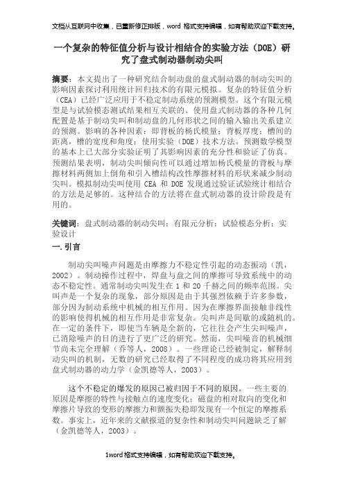
盘式制动器(八)——译自英国Lucas技术手册之八
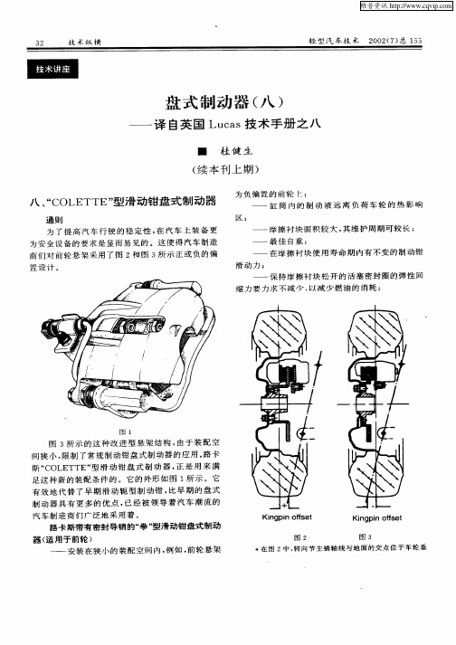
性 相对 好些 。
路 卡 斯 “ OL TTE” 滑 动 钳 盘 式 制 动 器 适 用 C E 型 于多种变 型的盘式制动器 上 。
— —
( 用 于 后 轮 , 有 驻 车制 动 及 自凋机 构 ) 适 带
通 则 为 了 提 高 汽 车 行 驶 的 稳 定性 , 汽 车 上 装 备 更 在 为 负 偏 置 的 前 轮 ;
— —
缸 筒 内 的 制 动 液 远 离 负 荷 车 轮 的 热 影 响 摩擦衬块面 积较大 , 维护 周期可较长 ; 其
最 佳 自重 ;
区 ;
— —
为安 全 设 备 的 要 求 是 显 而 易 见 的 。这 使 得 汽 车 制 造 商 们 对 前 轮 悬 架 采 用 了 图 2和 图 3所 示 正 或 负 的 偏
置 设计 。
—
—
—
—
在 摩 擦 衬 块 使 用 寿 命 期 内有 不 变 的 制 动 钳
滑 动力 ; 保 持 摩 擦 衬 块 松 开 的 活 塞 密 封 圈 的 弹 性 回
— —
缩 力 要 力 求 不 减 少 . 减 少 燃 油 的 消耗 ; 以
图 l
图 3所 示 的 这 种 改 进 型 悬 架 结 构 , 于 装 配 空 由 间狭 小 , 制 了常 规 制 动 钳 盘 式 制 动 器 的 应 用 。 卡 限 路
性 相 对差些 。
l .驻 车 制 动 横 杆 8 1 .保 持 弹 簧 9
技 术 纵 横
3 3
( 4 l 、 9三 零 件 并 非 所 有 制 功 器 装 用 . 、 1 、7 l 8 9通 常 为 ~
盘式制动器(一、二、三)——译自英国LUCAS技术手册之六

簧用来消除制动时产生的噪音
制动钳活摩的尺寸与数垃(2—1只).取决于台
适的装配空间和不同制动力的需要 ,例如 :为 r提供
前后轮间特殊的制动力 比率 ,前后轮制动钳 的活塞
尺寸和数量就会有差异。后轮制动钳 七的安装孔 ,可
用来装 置机械钳式驻车制动器.主要应 用在停车制
力。当制动盘热至 600C甚至更高 点,仍具有制动
能力和可得到的热稳定性 。
因此,糊动液在此恶 劣条件下 ,必须具有良好的
性能。路卡斯格林通用制动液具有近 290C的高沸
点、良好的化学稳定性致抗气温变化的能力,它杰出
的 性 能 完 全 符 合 EMVSS I)oT3 和 DDT4、
IsO4925、SAE70R3和 sAEJ1703等标准的规定。
的消耗也会随之增多,因而正常合用 的制动 摩擦衬
块 已成为保证汽车安全行驶的一个决定性因素
维普资讯 34 技术纵 横 轻 型汽 车技 术 2002(4)总 152
为什么同轴要使用『司 公司生产制动摩擦衬块
呢?这是因为各种型号汽车 所使用的制动摩擦材
料(不论是用于盘式或鼓式制动器)都是 由制造 厂家
驻车制动
驻车制动杆和钢索要接汽车制造厂的维修说 明
进行调整。如果驻车制 动杆行程过大 ,应按制造厂的
技术规定重新调整定位
一
般说明
汽车制动系统必顽保持绝对的清洁 糊动系统
的零部件决不要去接触润滑脂和矿物油 为 r清诘
制 动系统,通常使用 乙醇(酒精 )或丙醇 ,来 作清洁
剂 从矿物油中提取的油品是绝对禁止作为制动系
盘式制动器(九)——译自英国Lucas技术手册之九

1 .按 图 4所 示 , 拆 去 制 动 钳 体 低 处 的 导 向 销 旋
固定 螺 栓 , 防 止 导 向 销 的 转 动 , 用 合 适 的板 手 固 为 可
定 住 导 向销 。 在 操 作 中 , 小 心 勿 损 伤 导 向销 护 套 。 请 2 .按 图 5箭 头 所 示 , 制 动钳 体 以 高 处 导 向 销 将 螺栓为轴 心 , 向上 翻 起 。 为此 , 要 先 拆 开 驻 车 制 动 须
( ) 前推 动 内 擦 衬 块 ( ) 向 制 动 盘 。当 摩 擦 衬 b向 7压
块 ( ) 压 向制 动盘 ( ) , 筒 内 活 塞 的 反 作 用 力 9一 8时 缸 就 通过 推杆 ( ) 3 和球 形 槽 座 推 动 钳 体 沿 导 向 销 反 向 滑 动 , 凸 舌 推 动 外 峰 擦 衬 块 ( 0 压 向制 动 盘 ( ) 使 1) 8。 这 样 便 使 制 动 盘 两 边 与 摩 擦 衬 块 的 间 隙 消 失 , 同 并
负载 调 整 , 进 的 操 作 杆 系 统 , 准 产 品与 CHL 型 改 标 同时大量生 产于 19 9 1年 , 图 3所 示 。 如
安 全 说 明 基 于 安 全 的 理 由 , 便 是 功 能 性 故 障 问 题 发 生 即
在 个 别 的情 况 下 , 车 制 动 自动 调 整 系 统 也 会 同 时 驻 失 效 , 这 种 情 况 下 , 拆 下 盘 式 制 动 器进 行 检 修 。 在 应
调 整 装 置 作任 何 修 理 的 尝 试 。
九 、 COLETTE” “ CH 、 CHL、 HR C
拳 型 滑 动 钳 盘 式 制 动 器
( 置驻车制动) 内
通 则 Байду номын сангаас
基于ug的盘式制动器设计外文文献
一个复杂的特征值分析与设计相结合的实验方法(DOE)研究了盘式制动器制动尖叫摘要:本文提出了一种研究结合制动盘的盘式制动器的制动尖叫的影响因素探讨利用统计回归技术的有限元模拟。
复杂的特征值分析(CEA)已经广泛应用于不稳定制动系统的预测模型。
这个有限元模型是与试验模态测试结果相互关联的。
使用盘式制动器的各种几何配置是基于制动尖叫和制动盘的几何形状之间的输入输出关系建立的预测。
影响的各种因素:即背板的杨氏模量;背板厚度;槽间的距离,槽的宽度和角度;使用实验(DOE)技术方法。
预测数学模型的基本上已大部分实验证明了其影响因素的充分性和验证了仿真。
预测结果表明,制动尖叫倾向性可以通过增加杨氏模量的背板与摩擦材料两侧加上倒角和引入槽结构改性摩擦材料的形状来减少制动尖叫。
模拟制动尖叫使用CEA和DOE发现通过验证试验统计相结合的方法是足够的。
这种结合的方法将在盘式制动器的设计阶段是有用的。
关键词:盘式制动器的制动尖叫;有限元分析;试验模态分析;实验设计一.引言制动尖叫噪声问题是由摩擦力不稳定性引起的动态振动(凯,2002)。
制动操作过程中,焊盘与盘之间的摩擦可导致系统中的动态不稳定性。
通常制动尖叫发生在1和20千赫之间的频率范围。
尖叫声是一个复杂的现象,部分原因是由于其强烈依赖于许多参数,部分因为制动系统中机械的相互作用。
因为在摩擦界面接触非线性的影响使得机械的相互作用是非常复杂。
尖叫声是间歇的或随机的。
在一定的条件下,即使当车辆是全新的,它往往会产生尖叫噪声,已消除噪声的目的进行了更广泛的研究。
然而,尖叫噪音的机械细节尚未完全理解(乔等人,2008)。
一些理论已经被制定,解释制动尖叫的机制,无数的研究已经取得了不同程度的成功将其应用到盘式制动器的动力学(金凯德等人,2003)。
这个不稳定的爆发的原因已被归因于不同的原因。
一些主要的原因是摩擦的特性与接触点的速度变化;磁盘的相对取向的变化和摩擦片导致的变形的摩擦力和颤振失稳即发现有一个恒定的摩擦系数。
盘式制动器(七)—译自英国Lucas技术手册之七
组成“ AH” 带 有 驻 车 制 动 盘 式制 动 器’ 主要 型 的
零 部 件 , 图 5所示 。 如 制 动 摩擦 衬 块 的更 换
当制 动 摩 擦 衬 块 上 摩 擦 材 料 的 厚 度 已 磨 损 至
2 mm 以 内 , 摩 擦 衬 块 磨 损 极 限 指 示 灯 点 亮 时 , 或 均
螺栓 使 之 定位 。 装上 衬块 保 持 弹簧 , 保 摩 擦 衬块 与 确
车辆 前 进所 示 的箭 头方 向相 吻合 。 方 便 的话 , 手 若 顺 将 内摩 擦 衬块 磨损 极 限指 示灯 插 头接 上 , 并夹 固之 。 最 后 , 图 8所示 连续 踩 几脚 制 动踏 板 , 到 你 按 直 感 到制 动踏 板 有 阻力 时为 止 。 然后 , 查 制 动 液储 液 检 罐 的液 面 , 必要 时加 注制 动 液 至规 定 的 液面 位 置 。
工 作机 理描 述
块 5压 向制 动盘 。外活 塞 3通过 滑动 轭 1推 动 外摩
擦 块 6压 向制动 盘 , 图 3中箭头 所示 。 如
Ba ed c rk i 7 s
图 1所 示 的 这 种 AH 型后 轮 制 动 器 , 似 用 于 类
前 轮 的 A 型 活动 架 盘式 制动 器 。 动盘 与 摩擦 衬块 制
示。
A
●
B
图 3
^
‘
图 5
、 一
,
1 擦 衬块 保持 弹簧 2 .摩 .内 摩 擦 衬 块 3 .滑 动 轭 保 持弹簧 4 .弹 簧 5 .支 撑 块 6 .防 尘 罩 7 .内 保 持 环
8 .滑 动轭 9 .外 摩擦衬 块 l .衬块 保 持夹 l.六 角头 O 1
中英文文献翻译-盘式制动器的应用
附录A 外文文献原文China's engineers and users also stay in QianPan HouGu on the idea, and, before and after the application of the disc brake is commercial vehicle braking performance increase the optimal scheme. Because HouGu type brake on the temperature, the braking performance is very big, lead to the front axle attenuation disc brakes to bear on the part of the load, cause too much of the disc brake, brake piece of life of overload shorter. For cars in the braking process, because the role of the front, inertial load always takes all the car load 70% 80%, so the front wheel brake force to than the rear wheels. Manufacturers to cut costs, use the front disc brake, rear wheel drum brake mix of matching method. The QianPan HouGu type mixed brake, this is mainly due to the cost considerations. With the rapid development of China's national economy, the average consumer safety and environmental requirements of cars is increasing day by day, the miniature car industry from tiny truck started, the transition to tiny coaches, and then promoted to use tiny cars as transport, become the necessity of historical development; On the other hand, all miniature car companies already will capital and power steering mini car industry, to adapt to the different needs of consumers out mini car products, some private enterprises will also mini car into the breach of the car market as, constantly of price war, make mini car prices have no longer "too high", and began to close to ordinary people.Disc brake caliper disc and main overall type two kinds, modern car on the application of the most caliper disc brake, it is the rotation of the element is brake disc, fixed element is brake caliper. And, according to the brake caliper movement way and can be divided into set caliper disc brake, sliding caliper disc brake caliper disc brake and, including sliding caliper disc brake application more widely. The working principle of caliper disc brake is similar to a bicycle brake, braking process, the brake caliper will brake piece of extrusion to brake disc, along with the brake disc and lining block of the friction between the gradually will fall speed. And sliding caliper disc brake is brake caliper can be relatively brake disc axial sliding; Only in the inside of the brake disc set oil cylinders, and the outside of the brake block is in the grips attached on the body. Disc brakes in use process, also can appear fault, among them the more common wind resistance, underpowered and brake system has noise etc.Disc brake parts of fever in a narrow focus on the brake lining block, the unit and pressure than drum brakes, brake lining large block and clamp body of the piston direct contact with, so the quantity of heat of braking extremely easily to the brake fluid. So, make disc brakes easy to produce gas resistance phenomenon. But, if take corresponding measures, also can prevent air resistance happens.Miniature and affordable in our country are big car market, in recent years the domestic demand expansion drive the car market demand for miniature of the increase. Authorities say China's economy has entered into the platform, the moderate growth will pull the stable growth of car market. Last year, Chinese each enterprise benefits to improve, per capita disposable income increase, cause individual needs to improve the car; Countries carrying out the strategy for western development, to WeiChe market is tremendous potential demand of no doubt. From 0.9 to 1.6 L L, the price is suitable for China's national conditions, suitable for the current status of the development of the China is. Automobile brake clamps body stent is one of important parts, along with the car now design processing development of manufacturing technology, the brake clamps body in support of materials and processing method and so on is also in constant development, identify processing technology and clamping plan and design, attain thus to the automobile brake clamps body stents processing technology further deeper understanding;The main use of the software has Pro/e, ANSYS and CAPP. Pro/E software using 3 d entity the exact modeling, intuitive parts to reproduce the parts, accurate experience design intention, for parts of the process arrangement after help. Pro/E Mechanica module and the software ANSYS software, finite element analysis, combining do analysis processing produces in the process of the maximum displacement and the maximum stress, and the cutting tool for cutting dosages of the size of the choice to provide reliable basis. This topic use CAPP software developed including making the process route and process design, the complete process documents and improve the process of standardization and standardization. Early detection and solve. According to the retrieval, this in processing industries, and no one made the corresponding introduction. Pro/E software can be accurately to establish various large and complex models. ANSYS software in products manufacturing advance found potential problems, but its modeling ability are weak. The two tools combined, foster strengths and circumvent weaknesses, give full play to the advantages of two kinds of software research and development, is the first choice of complex mechanical structurescheme. This is also I choose the two software reasons. Previous engineering personnel with Pro/E complete three dimensions solid parts design, then use to Mechanica parts structure finite element analysis to find the place, and weak structure is improved. And I'm Pro/E, ANSYS will be applied to the design process of parts, make the past only in process actual implementation, can come into the open process defect, process design stage in can and The error after reflects the workpiece machining allowance method to calculate is, by definition, the processing, surface: its smallest machining allowance (Zbmin) are processing parts of two adjacent step freeways will limit of the difference of the minimum size; Its the biggest machining allowance (Zbmax) are processing parts of two adjacent step freeways will limit of the difference of the largest size. Inside surface processing, the minimum machining allowance is processed spares the maximum limit adjacent freeways will step size poor; Its the biggest machining allowance is processing components work of two adjacent step of the difference of the minimum size limit.The assistant time and basic time coincidence method, using the workbench processing center, get the staff in the cutting process completed work, and then, for auxiliary of the area is larger, and the volume of parts and relatively small, so can use one processing DuoGe parts to make the parts, the piece processing time as little as the basis, double the nc machining center area can also arranged four parts. The rotary worktable, two workpiece in processing at the same time, the clamping workpiece, the other two rotating, processing of just install two workpiece.Selection of cutting parameter and the formulation of &fair standards. Choose the right to improve the cutting dosages, cutting efficiency and guarantee the necessary tools durability and economy, ensure machining quality, has the vital role. Reasonable choice when processing cutting dosages should first choose a as far as possible big, secondly, optimizing the back of choice a larger feeding, and the last in the cutting tool durability, process system stiffness, machine tool power under the terms of the license, the rational choice of cutting speed. &fair standards also says time is fixed in a certain technology organization established under the condition of complete unit out products (such as a parts) or a job (such as a process that must be consumed time). &fair standards is not only, also be the measure index productivity arrange production plan, the calculations of the productioncost is an important basis for new or expansion of the factory, is also (or workshop) computing devices and workers number of basis.Brake caliper disc brake the car body is the critical, brake movement is in the grips body on the final. Installed in clamp body on parts and 16 pieces. One of the more important parts: brake caliper piston, piston callipers at the stents, sealing ring, friction piece, brake caliper shaft pins, spring of and purge screw, etc. Studio, brake fluid through the clamp body JinYou mouth will be pressure to brake caliper Detroit, and by the brake friction pressure before the pistons will to block, press the brake disc, and make clamp body in the brake caliper shaft pins, driving the sliding friction, also after pressure brake disc brake, complete action. The car brake disc brake caliper body shape, structure, material complex special for QT450-10, hardness is HB143-217, machining allowance for 3 mm, form and position tolerances stricter requirements. This product is the important parts, and related to China's automobile brake disc importied problem. In the existing gm in machine tool is completed or processing difficult brake caliper body, especially the lumen of processing, tank must determine the process, to ensure the quality of the processing equipment. Because in general on the machine processing, so blank datum positioning to repeated use, the request to have the precise location of the datum plane, this and use machining center is a very big difference. Such as we are in the process of slot PNE480 CNC machine even with pure inside the car, to ensure that slot cavity type, detection is precision with anatomical projection and after adjustment method of projection.Were now being mass production craft ready to work, according to the auto industry "high starting point, large quantities of specialization," the policy, we have identified on the domestic equipment, save funds, and choose the XK6040 CNC milling machine.附录B 外文文献翻译中国的工程师和用户还停留在前盘后鼓的理念上,而前、后盘式制动器的应用才是商用车提高制动性能的最佳方案。
毕业设计译文(盘式制动器)

A disc brake test stand for measurement of airborne wear particlesABSTRACTDuring braking, there is wear on both the rotor and the pads. This process generates particles that may become airborne. In fi eld tests, it is diffi cult to distinguish these particles from others in the surrounding environment.Therefore, a laboratory test stand has been designed which allows control of the cleanliness of the surrounding air. The test stand consists of a front right brake assembly mounted in a sealed chamber. A braking load is applied by a pneumatic system and the rotor, which has been pre-conditioned with a rust layer to simulate a car standing parked overnight in a wet environment, is driven by an electric motor. The number and size of airborne wear particles are then measured. This experimental set-up has been verifi ed by an initial test series performed at low braking loads. The results suggest that this test stand can be used to study rust layer removal from the rotor.key words: wear; airborne particles; disc brake; test stand; rust layerINTRODUCTIONMany studies have shown an association between adverse health effects and the concentration of airborne particles in the atmosphere.1–3 In urban environments, airborne particles can come from different sources, e.g. demolition and construction,4 resuspended road dust,5 wheel-to-rail contact,6,7 car-to-road contact8,9 and disc brakes.10,11 During braking, both the brake pads and rotors are worn, generating wear particles. Some of these particles are deposited on the brake hardware, and others become airborne. Furthermore, to ensure robust brake performance, some brake systems may require the pads to frequently be in low pressure contact with the rotor. This dragging may remove any rust layer, which may build standing parked overnight in a wet environment, from the rotor and keep the contact surfaces clean. However, the resulting drag torque increases the fuel consumption and generates wear particles, because the pads are still in contact with the rotor after the rust layer has been removed. It is therefore desirable to reduce the dragging without affecting the performance of the brakes.When measuring airborne brake particles in fi eld tests, it can be diffi cult to distinguish them from other traffic-generated aerosols. Therefore, it may be preferable to use laboratory tests that allow control of the cleanliness of the surrounding air. Although several test stands have been built to study wear and friction at the pad-to-rotor interface, few studies12,13 have focused on wear particles. In a laboratory test stand, the cleanliness of the surrounding air can be controlled, enabling more accurate study of airborne brake wear particles. With this in mind, a laboratory component test stand has been designed to measure the number and size of airborne wear particles generated by disc brakes. The purpose of this paper was to describe this test stand and present the results of a fi rst test series to verify the experimental set-up. These tests focus on rust layer removal at low braking loads.EXPERIMENTAL SET-UPIn this test stand, a front right brake assembly from a passenger car is used. The front right brake assembly consists of a knuckle, the wheel bearing and the disc brake assembly. The disc brake assembly in turn consists of a ventilated rotor, a sliding caliper with a single piston and two brake pads (Figure 1). The fi nger side brake pad includes a K-typethermocouple that measures the temperature near the fi nger side pad-to-rotor contact.A schematic diagram of the test stand is given in Figure 2. An electric direct current motor (K) with a nominal torque of 191 Nm drives the rotor, and a pneumatic system (M) connected to the front right brake assembly (H) is used to apply a controlled braking load. When the brake is applied, the motor continues to drive the system at a stationary rotational speed, i.e. the test system throttles and brakes at the same time. A drive shaft (L) transfers the torque from the motor to the wheel bearing, which in turn rotates the disc. The motor and the drive shaft are connected by a fi xed coupling, and the wheel bearing and the drive shaft are connected by a splined coupling. The knuckle is mounted to a suspension device. A sealing chamber (G) seals the front right brake assembly from the surroundings. The electric motor is balanced with bearings on each end. The applied torque on the motor is measured using a calibrated strain gauge force sensor multiplied by the distance from the motor centre,with an accuracy of ±2.2%. The rotational speed of the disc is measured by a built-in Hall effect sensor in the wheel bearing, with 48 pulses per revolution. A pneumatic system generates controlled low pressure levels of up to 4 bar in the brakecylinder. The pressure level is measured with an accuracyof ±0.5% by a calibrated piezoelectric pressure sensor near the inlet of the brake cylinder.盘式制动器试验台上测量空气中磨损颗粒摘要在制动过程中,制动盘和摩擦片都有磨损。
中英文文献翻译-盘式制动器

中英⽂⽂献翻译-盘式制动器附录ADisc BrakesDisc brakes are used on the front wheels of most cars and on all four wheels on many cars. A disc rotor is attached to the wheel hub and rotates with the tire and wheel. When the driver applies the brakes, hydraulic pressure from the master cylinder is used to push friction linings against the rotor to stop it.In the disc brake rotor assembly, the rotor is usually made of cast iron. The hub may be manufactured as one piece with the rotor or in two parts. The rotor has a machined braking surface on each face. A splash shield, mounted to the steering knuckle, protects the rotor from road splash.A rotor may be solid or ventilated. Ventilated designs have cooling fins cast between the braking surfaces. This construction considerably increases the cooling area of the rotor casting. Also, when the wheel is in motion, the rotation of these fan-type fins in the rotor provides increased air circulation and more efficient cooling of the brake. Disc brakes do not fade even after rapid, hard brake applications because of the rapid cooling of the rotor.The hydraulic and friction components are housed in a caliper assembly. The caliper assembly straddles the outside diameter of the hub and rotor assembly. When the brakes are applied, the pressure of the pistons is exerted through the shoes in a ‘clamping’ action on the rotor. Because equal opposed hydraulic pressures are applied to both faces of the rotor throughout application, no distortion of the rotor occurs, regardless of the severity or duration of application. There are many variations of caliper designs, but they can all be grouped into two main categories: moving and stationary caliper. The caliper is fixed in one position on the stationary design. In the moving design, the caliper moves in relation to the rotor.Most late-model cars use the moving caliper design. This design uses a single hydraulic piston and a caliper that can float or slide during application. Floating designs ‘float’or move on pins or bolts. In sliding designs, the caliper sideways on machined surfaces. Both designs work in basically the same way.In the single piston floating caliper, the single-piston caliper assembly is constructed from a single casting that contains one large piston bore in the inboard section of the casting.Inboard refers to the side of the casting nearest the center line of the car when the caliper is mounted. A fluid inlet hole and bleeder valve hole are machined into the inboard section of the caliper and connect directly to the piston bore.The caliper cylinder bore contains a piston and seal. The seal has a rectangular cross section. It is located in a groove that is machined in the cylinder bore. The seal fits around the outside diameter of the piston and provides a hydraulic seal between the piston and the cylinder wall. The rectangular seal provides automatic adjustment of clearance between the rotor and shoe and linings following each application. When the brakes are applied, the caliper seal is deflected by the hydraulic pressure and its inside diameter rides with the piston within the limits of its retention in the cylinder groove. When hydraulic pressure is released, the seal relaxes and returns to its original rectangular shape, retracting the piston into the cylinder enough to provide proper running clearance. As brake linings wear, piston travel tends to exceed the limit of deflection of the seal; the piston therefore slides in the seal to the precise extent necessary to compensate for lining wear.The top of the piston bore is machined to accept a sealing dust boot. The piston in many calipers is steel, precision ground, and nickel chrome plated, giving it a very hard and durable surface. Some manufacturers are using a plastic piston. This is much lighter than steel and provides for a much lighter brake system. The plastic piston insulates well and prevents heat from transferring to the brake fluid. Each caliper contains two shoe and lining assemblies. They are constructed of a stamped metal shoe with the lining riveted or bonded to the shoe and are mounted in the caliper on either side of the rotor. One shoe and lining assembly is called the inboard lining because it fits nearest to the center line of the car. The other is called the outboard shoe and lining assembly.As already mentioned, the caliper is free to float on its two mounting pins or bolts. Teflon sleeves in the caliper allow it to move easily on the pins. During application of the brakes, the fluid pressure behind the piston increases. Pressure is exerted equally against the bottom of the piston and the bottom of the cylinder bore. The pressure applied to the piston is transmitted to the inboard shoe and lining, forcing the lining against the inboard rotor surface. The pressure applied to the bottom of the cylinder bore forces the caliper to move on the mounting bolts toward the inboard side, or toward the air. Because the caliper is one piece, this movement causes the outboard section of the caliper to apply pressure against the back of the outboard shoe and lining assembly, forcing the lining against the outboard rotorsurface. As the line pressure builds up, the shoe and lining assemblies are pressed against the rotor surfaces with increased force, bringing the car to a stop.The application and release of the brake pressure actually causes a very slight movement of the piston and caliper. Upon release of the braking effort, the piston and caliper merely relax into a released position. In the released position, the shoes do not retract very far from the rotor surfaces.附录B外⽂翻译:盘式制动器许多汽车所有四个车轮,盘式制动器是⽤在⼤多数轿车的前轮上。
(完整版)汽车制动系统-英文文献及翻译

Brake systemsWe all know that pushing down on the brake pedal slows a car to a stop. But how does this happen?How does your car transmit the force from your leg to its wheels? How does it multiply the force so that it is enough to stop something as big as a car?Brake Image GalleryLayout of typical brake system. See more brakeimages。
When you depress your brake pedal, your car transmits the force from your foot to its brakes through a fluid. Since the actual brakes require a much greater force than you could apply with your leg, your car must also multiply the force of your foot. It does this in two ways:•Mechanical advantage (leverage)•Hydraulic force multiplicationThe brakes transmit the force to the tires using friction, and the tires transmit that force to the road using friction also。
Before we begin our discussion on the components of the brake system, we’ll cover these three principles:•Leverage•Hydraulics•FrictionLeverage and HydraulicsIn the figure below, a force F is being applied to the left end of the lever. The left end of the lever is twice as long (2X) as the right end (X)。
关于盘式制动器的参考文献

关于盘式制动器的参考文献
以下是关于盘式制动器的一些参考文献,供你参考:
1. "Automotive Brake Systems" by James D. Halderman 这
本书是关于汽车制动系统的综合指南,其中包括盘式制动器的原理、设计和性能分析等内容。
2. "Brake Design and Safety" by Rudolf Limpert 这本书详细介绍了制动系统的设计和安全性能,包括盘式制动器的设计原理、材料选择和制动力分析等方面。
3. "Brake Handbook" by Fred Puhn 这本手册提供了关于制动系统的全面介绍,包括盘式制动器的原理、设计、维护和故障排除
等方面的内容。
4. "Vehicle Brake Systems: A Textbook for Technicians" by Tom Denton 这本教材专门为汽车技术人员编写,涵盖了制动系
统的各个方面,包括盘式制动器的工作原理、构造和维护等内容。
5. "Brake Technology Handbook" by Bert Breuer and
Karlheinz H. Bill 这本手册提供了关于制动技术的详细信息,包括盘式制动器的设计、材料和制动系统的性能评估等方面的内容。
这些参考文献涵盖了盘式制动器的原理、设计、性能和维护等方面的知识,可以帮助你更全面地了解盘式制动器的工作原理和应用。
请根据你的具体需求选择适合的文献进行深入研究。
- 1、下载文档前请自行甄别文档内容的完整性,平台不提供额外的编辑、内容补充、找答案等附加服务。
- 2、"仅部分预览"的文档,不可在线预览部分如存在完整性等问题,可反馈申请退款(可完整预览的文档不适用该条件!)。
- 3、如文档侵犯您的权益,请联系客服反馈,我们会尽快为您处理(人工客服工作时间:9:00-18:30)。
机械工程学院毕业设计(外文翻译)附件外国文献HYDRAULIC BRAKE BASICSAir brakes get more attention, but hydraulic brakes are installed on more vehicles. Understanding how they work is the first step to safe, cost-effective diagnosis and repair.Ever wonder why there can't be just one kind of brake? It's because airand h ydraulic brakes each have operating characteristics that make one or the other ideal for certain applications.In heavy-duty combination vehicles, air is the clear choice because of the large volume of liquid that would be needed to CATIA all the wheel cylinders. Plus, dealing with glad hand and hoses filled with hydraulic fluid would be messy.But for light and medium-duty straight-truck applications, hydraulic brakes offer advantages including:•Brake feel — that is, as the pedal is pressed farther down, effort increases;•High line pressures, which permit the use of lighter, more compact braking components;•Less initial expense, due to smaller and fewer components;•Cleanliness — hydraulic brakes are closed systems;•Ease of locating leaks, since fluid is visible.There are many more permutations of hydraulic brake systems than found in air systems, but all have basic similarities.THE HYDRAULIC SYSTEMAll hydraulic brake systems contain a fluid reservoir, a master cylinder, whichproduces hydraulic pressure, hydraulic lines and hoses to carry pressurized fluid to the brakes, and one or more wheel cylinder(s) on each wheel.The wheel cylinders expand under fluid pressure, and force the brake shoes against the insides of the drums. If disc brakes are used, calipers, with integral cylinders, clamp down on the rotors when pressure is applied.Because a vehicle must be able to stop much more quickly than it can accelerate, a tremendous amount of braking force is needed. Therefore, the retarding horsepower generated by the brakes must be several times that of the engine.In order to develop the forces required to hold the brake linings against the drums or discs, and to achieve controlled deceleration, it is necessary to multiply the original force applied atthe brake pedal.When a hydraulic system is used, the only mechanical leverage is in the foot pedal linkage. However, varying the diameter of the wheel cylinders or caliper diameters, in relation to the master cylinder bore diameter, provides an additional increase in ratio.In a hydraulic system, the pressure delivered by the various wheel cylinders is directly affected by the areas of their pistons. For example, if one wheel-cylinder piston has an area of 2 square inches, and another piston has an area of 1 square inch, and the system pressure is 400 psi,the 2-square-inch piston will push against the brake shoes with a force of 800 pounds. The1-square-inch piston will exert a force of 400 pounds. The ratio between the areas of the master cylinder and the wheel cylinders determine the multiplication of force at the wheel cylinder pistons.Keep in mind that the larger a wheel cylinder's diameter, the more fluid must be supplied by the master cylinder to fill it. This translates into a longer master-cylinder stroke.If the master cylinder bore diameter is increased and the applying force remains the same, less pressure will be developed in the system, but a larger wheel-cylinder piston can be used to achieve the desired pressure at the wheel cylinder. Obviously, a replacement master cylinder, wheel cylinder or caliper must be of the same design and bore as the original unit.Hydraulic brake systems are split systems, comprising two discreet braking circuits. One master-cylinder piston and reservoir is used to actuate the brakes on one axle, with a separate piston and reservoir actuating the brakes on the other axle(s). Although rare, some light-duty brake systems are split diagonally rather than axle by axle.The reason for the split system is that if a leak develops in one hydraulic circuit, the other will stop the vehicle. Of course, the vehicle shouldn't be driven any farther than necessary to havethe brake system repaired.When one of the hydraulic circuits fails, a pressure -differential switch senses unequal pressure between the two circuits. The switch contains a piston located by a centering spring and electrical contacts at each end. Fluid pressure from one hydraulic circuit is supplied to one end of the pressure-differential switch, and pressure from the other circuit is supplied to the other end. As pressure falls in one circuit, the other circuit's normal pressure forces the piston to the inoperative side, closing the contacts and illuminating a dashboard warning light.POWER ASSISTPower assist units, or boosters, reduce operator effort at the brake pedal. Vacuum boosters, popular on light-duty vehicles, make use of an engine vacuum on one side of a diaphragm, and atmospheric pressure on the other side. A valve allows the vacuum to act on the diaphragm in proportion to brake pedal travel. This assists the pedal effort, and allows increased pressure onthe brake fluid, without an undue increase in pedal effort.Other types of boosters use hydraulic pressure — either from the vehicle's power steering pump or from a separate electric pump, or both — to assist pedal effort. As the brake pedal is depressed, a valve increases hydraulic pressure in a boost chamber to apply increased pressure to the master cylinder pistons.Some systems use both vacuum and hydraulic assist. In other systems, air pressure from an onboard compressor is used to generate hydraulic system pressure.VALVINGValves commonly found in hydraulic brake systems include: Proportioning, orpressure-balance valves. These restrict a percentage of hydraulic pressure to the rear brakes when system pressure reaches a preset high value. This improves front/rear brake balance duringhigh-speed braking, when some of a vehicle's rear weight is transferred forward, and helps prevent rear-wheel lockup. Some proportioning valves are height-sensing. That is, they adjustrear-brake pressure in response to vehicle load. As a vehicle's load increases (decreasing height) more hydraulic pressure to the rear brake s is allowed;Metering valves. These hold off pressure to front disc brakes to allow rear drum brake shoes to overcome return-spring pressure and make contact with the rear drums. This prevents locking the front brakes on slippery surfaces under light braking applications. These valves do not come into play during hard braking.PARKINGThe parking function varies greatly among hydraulic brake systems. Many light-duty vehicles with rear drum brakes use a passenger-car type lever-and-cable setup. A ratcheted lever or foot pedal pulls a cable, which, in turn, pulls a lever assembly at each rear wheel end. The lever forces the brake shoes apart, and they are mechanically held against the drums until the ratchet is released.Other parking systems include spring chambers, like those used onair-brake systems. These are spring-engaged, but are disengaged by hydraulic pressure instead of air.ANTILOCKOn many hydraulically braked light-duty trucks, brakes are used on the rear wheels to preserve braking stability when these vehicles are lightly loaded. Front and rear-wheel is usually an option, except for vehicles over 10,000 pounds GVWR, which are required to have steer and drive-axleIn current hydraulic systems, a dump valve releases pressurized hydraulic fluid into an accumulator in the event of an impending wheel lockup.An electronic control box receives speed signal(s) from sensors in the transmission and/or at the wheels. When the brakes are applied, the control box senses the decrease in rear wheel speed, and activates the dump valve(s) if the rate of deceleration exceeds a predetermined limit.The control box energizes the dump valve with a series of rapid pulses to bleed-offwheel hydraulic pressure. Continuing in mode, the dump valve is pulsed to keep the wheels rotating, while maintaining controlled deceleration.At the end of such a stop, the valve and any fluid in the accumulator is returned to the master cylinder. Normal brake operation resumes.FOUNDATION BRAKESFoundation brakes in hydraulic systems can be either drum or disc. In many applications, discs are used on the front axle and drums on the rear.Drum brakes are said to be self-energizing. That's because when the brake shoes expand and contact a rotating drum, the leading, or forward, brake shoe is pushed against the trailing shoe by the force of the moving drum. This results in higher lining-to-drum pressure than would be produced by the wheel cylinder alone.As brake linings wear, the shoes periodically must be moved closer to the drums to ensure proper contact during braking. While some older drum brake assemblies are manually adjusted, most are automatic. These use a star wheel or ratchet assembly, which senses when the wheel cylinder has traveled beyond its normal stroke, and expands the pivot point at the other end ofthe brake shoes.In addition to being one of the friction elements, the brake drum or rotor also acts as a heat sink. It must rapidly absorb heat during braking, and hold it until it can be dissipated into the air. The heavier a drum or rotor is, the more heat it can hold.This is important, since the hotter the brake linings get, the more susceptible they are to heat fade. Heat fade is induced by repeated hard stops and results in reduced lining-to-drum/rotor friction and increased vehicle stopping distance. As a rule, high-quality linings will display less heat fade than inferior ones. Also, are far more resistant to heat fade than drum brakes.Another type of fade that brakes are susceptible to is water fade. Drum brakes, with their large surface areas, apply fewer pounds per square inch of force between lining and drum during a stop than disc brakes. This, added to the drum's water-retaining shape, promotes hydroplaning between shoe and drum under wet conditions. The result is greatly increased stopping distance.Disc brakes, with their smaller friction surfaces and high clamping forces, do a good job of wiping water from rotors, and display little reduction in stopping capability when wet.中文翻译液压制动基础空气制动系统得到更多的关注,但更多的车辆上安装液压制动器。