产品管理-信号源基础知识及安捷伦产品
安捷伦 Agilent 34420A纳伏 微欧表 说明书

10mA 10mA 10mA 1mA 100µA 10µA 5µA
0.0025+.0020 0.0025+.0002 0.0015+.0003 0.0010+.0003 0.0002+.0001 0.0010+.0004
0.0015+.0002 0.0015+.0002 0.0015+.0002 0.0015+.0002 0.0015+.0002 0.0015+.0003 0.0020+.0003
0.0050+.0002 0.0040+.0002 0.0040+.0002 0.0040+.0002 0.0040+.0004 0.0040+.0015 0.0050+.0004
0.0070+.0002 0.0060+.0002 0.0060+.0002 0.0060+.0002 0.0060+.0004 0.0060+.0015 0.0070+.0004
位数
7 1/2 7 1/2 6 1/2 6 1/2 5 1/2 5 1/2 4 1/2 7 1/2 7 1/2 6 1/2 6 1/2 5 1/2 50(50) 4 1/2 125(125)
积分时间
200plc 100plc 20plc 10plc 1plc 0.2plc 0.02plc 200plc 100plc 20plc 10plc 1plc
DC 电压 vs 源电阻 10
源电阻 0 100 1k 10k 100k 1M
噪声 1.3nVrms 1.7nVrms 4nVrms 13nVrms 41nVrms 90nVrms
安捷伦信号发生器选型指南

T-DMB, DAB/DAB+/DMBaudio, FM stereo with RDS/ RBDS
侦测、定位、跟踪和导航
脉冲生成
●
脉冲序列
GPS
●
GLONASS
PSG MW 模拟 E8257D
● ● ● ●
MXG MW MXG 和 MXG 和 模拟 EXG RF 矢量 EXG RF 模拟
N5183A
微波矢量与模拟 射频模拟 X 系列信号发生器 ......................................................10 MXG 矢量与模拟 EXG 矢量与模拟 模拟信号发生器 .........................................................12 基带发生器和接口模块 ............................................13 模块化产品 ..................................................................14 从传统信号发生器过渡 ............................................15
安捷伦信号发生器选型指南
提升信号生成标准
简介
安捷伦提供从基带到 67 GHz ( 频率可进一步扩展到 500 GHz) 的广泛信号发生器选择。从基础功能到高级特性, 每款信号发生器都为同级别产品树立了性能标准,能够 满足无线电收发机及组件的设计和制造要求,可涵盖从 低频导航信号到蜂窝移动无线电再到毫米波雷达和卫星 系统的应用范围。另外,每款信号发生器都可提供合成 频率准确度和稳定性、卓越的校准电平精度和远程可编 程功能。
安捷伦PXA信号分析仪产品手册

幅度精度
± 0.19 dB
实时带宽
160 MHz; 频率范围高达 50 GHz
截获概率
100%, 信号宽度窄至 3.57 μs
2
推动您的演进
在实际的信号分析中,仪器的 演进能力通常意味着您的成功。对 于未来设计,出色的测量性能能够 保证对复杂信号进行详细分析; 对于 现有技术,设备的通用性能可帮助 您降低产品成本; 对于传统测试系 统,继承式更新换代能够确保持续 的稳定性。
使用 SNS 或 346 系列噪声源和 N9069A 测量应用软件进行噪声 系数测量。
使用外部触发输入信号 对指定事件进行测量。
使用外部触发输出信号将分 析仪与其它测试设备同步。
用于日后应用 的数字总线。
7
/find/pxa
相关文献
内置功能让您做得更多, 优化连通性和控制
PXA 支持 USB 功率探头和安捷 伦智能噪声源 (SNS 系列),能够进行 功率和噪声系数测量。作为系统控 制器,PXA 还可以通过 GPIB、LAN 和 USB 端口以及 Windows XP Pro 操作 系统控制其它仪器。在控制器模式 下,PXA 可以取代测试系统 PC,因 此有可能简化系统体系结构以及机 密军事 ATE 应用的安全程序。外部混 频器还支持您测量频率高达 325 GHz 及以上的信号。
“面向未来”是什么意思
一个真正的面向未来的信 号分析仪具有高度灵活性,能够 升级并增强所有主要的子系统: 机械、电子、固化软件和软件。 PXA 分析仪能够在上述 4 个方面 进行升级和增强:
● 仪器组件能够提供 7 个扩展插 槽,以用于增强未来功能
● 可拆卸的 CPU 主板,能够支持 CPU、存储器和 I/O 升级
探索演进标准
安捷伦仪器使用说明书中文

Alpha安捷伦B1500A半导体器件分析仪用户!ˉ的GUID安捷伦科技公司声明?安捷伦科技公司2005年,2006年,2007年,2008本手册的任何部分不得转载任何形式或通过任何手段(包括电子电子存储和检索或翻译成外国语言)事先同意MENT和安捷伦的书面同意作为由美国科技公司在美国和国际版权法。
手册部件号B1500-90000版2005年7月第1版,第2版,2005年12月2006年4月第3版第4版,2007年1月2007年6月5日,版第6版,2007年11月2008年10月7日,版安捷伦科技公司5301史蒂文斯溪大道95051美国加利福尼亚州圣克拉拉保证本文档中所含的物质是提供MENT!°为是,±,是苏如有更改,恕不另行通知,在以后的版本。
此外,最大而且,在适用法律法律,安捷伦提供任何保证,明示或暗示,关于本手册的任何信息所载,包括但不不限于隐含保证为杆的适销性和适用性特定用途。
安捷伦不得承担错误或偶然或在相应的损害赔偿连接TION的家具,使用,或每本文件或任何性能所载资料。
应该安捷伦与用户有一个单独的与保修的书面协议在这个物质的范围,涵盖记录与这些冲突条款,在保修则以协议arate中的协议为准。
技术许可硬件和/或软件描述这份文件是依照许可可用于复制或只在雅跳舞的许可条款。
有限权利如果软件在使用的一种表现美国政府的首要合同或道,软件交付和许可!°商业计算机软件!±ADFAR252.227-7014(1995年6月)的定义,或作为一个!°商业项目!FA±定义2.101(a)或°有限计算机软!洁具!±作为定义在FAR52.227-19(六月1987)或任何相当机构法规或合同条款。
使用,重复或disclo的软件肯定是受安捷伦科技nologies!ˉ标准商业许可条款和非DOD部门和美国政府机构没有获得更大而不是限制权利定义在FAR 52.227-19中(C)(1-2)(6月1987年)。
Agilent N9310A 射频信号发生器 说明书

全量程输入: 调制频率范围:
载波抑制: QPSK EVM: GMSK 相位误差: 连接端口和输入阻抗:
外部 I/Q 输入 < 1.5 (I2+Q2)=0.5 Vrms DC to 40 MHz 40 dBc 3% 1.2° rms BNC 阴头; 50 Ω
远控
USB 主控端口: 3xA 插口 USB 设备端口: 1xB 插口
分辨率: 调制频率: 偏移精度: 总谐波失真: 外部输入:
灵敏度: 输入阻抗:
(载频 100 KHz 以上)
内部 0 到 10 rad 0 到 5 rad < 1% 300 Hz 到 20 kHz. < ± (设置值的 5% + 0.2 rad) < 1.5%
1 Vp BNC; >100 kΩ (标称值)
汉英双语提升了产品的通用性
随着业务的全球化拓展,您的工程 师和技术人员遍布世界各地。因此, 在多语言环境下操作测量仪器的挑 战实际上已经成为一个基本的需求。
对此需求,N9310A射频信号发生器 可以迎刃而解。
针对屏幕上显示的操作信息, N9310A 射频信号发生器内置了英 语和汉语两种语言。不久,其它语言 的选件也将陆续推出。
6
经济合理的价格、迅速完美的支持 当您在教学、生产、研发、安装过程或 者维护计划中使用安捷伦的测试仪器 时,一旦遇到难题,您可以信赖安捷伦 — 您将获得令您满意的客户支持。 您可以深信,您正在做物有所值的正 确选择。
实用性的价值对您意味着什么
安捷伦科技新一代结构紧凑、成本低廉的测试仪器系列
我们深信安捷伦的 N9310A 射频 信号发生器能够充分满足您的需 求,请体验它的实用性,满怀信心 的订购。
安捷伦 3000T X 系列示波器说明书
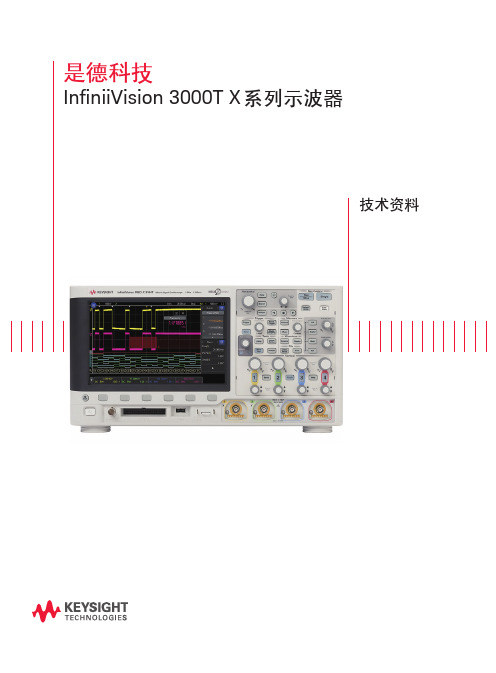
InfiniiVision 3000T X 系列示波器
技术资料
02 | Keysight | InfiniiVision 3000T X 系列示波器-技术资料
简洁的触控操作、揭示偶发异常轻松解决问题
InfiniiVision 3000A X 系列示波器将重新定义示波器。它能查看最详细的信号细节,比任 何其他示波器提供更多更出色的功能,更有效地保护您的投资。它同时也是惠普、安捷 伦以及是德科技的示波器系列中最成功的一款。如今,3000T X 系列将延续传统,再创 新高。 3000T X 系列在 3000A 系列的创新性能的基础上,新增了电容式触摸屏、触摸式用户界 面以及独一无二的区域触摸触发技术。所有这些增强特性结合业界领先的毫不妥协的波 形捕获率 100 万个波形/秒,可确保您能够查看完整的信号细节,并能发现任何潜在的 问题。新的分析功能将会帮助您快速解决最棘手的问题。 3000T X 系列重新定义了通用示波器的使用体验,为您提供所需要的全部性能和功能, 以使您能够更迅速地进行测量分析。
94%
1,114,000
94%
1,100,000
94%
1,113,000
94%
1,113,000
94%
Tektronix MDO3000 系列 波形捕获率 281,000 132 2,200 2,200 1,800 2,200 2,200
概率 50% 0.03% 0.55% 0.55% 0.45% 0.55% 0.55%
什么是波形波形捕获率 ?
当示波器采集、处理数据并在屏幕上绘制数据图形时,不可避免存在 "死区时间",也就 是示波器完全遗漏信号的时间。总之,波形更新率越快,死区时间越短。死区时间越 短,示波器越有可能捕获到异常和偶发的事件。因此,选择具有极快波形更新率的示波 器至关重要。图 7 和 8 展示了示波器在两种波形捕获率下的区别。
Agilent E4887A HDMI TMDS信号发生器平台技术资料版本2.1
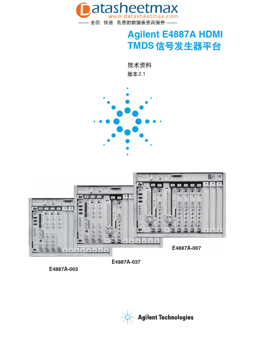
用户可以选择众多的视频格式。帧发生器测试软件能够把 TMDS 信号发 生器设置为用户选择的格式,并可非常方便地控制抖动注入。
集成的一致性测试软件
N5990A 自动测试软件将 E4887A HDMI TMDS 信号发生器平台和 DSO90000 系列实时示波器集成在一起构成完整的测试系统。该 HDMI 接收 机测试解决方案可提供经过校准的抖动注入,以极高的测试速率进行精确的 抖动容限表征和一致性测试。
信号源测试解决方案
DSO90000 系列示波器是安捷伦信号源测试解决方案的核心。这些实时 示波器的高带宽、低噪声和出色的探测能力,可显示出 HDMI 信号源的清晰 眼图和实际裕量。N5399A 软件可指导用户自信地完成大多数一致性信号源 测试。
电缆测试解决方案
E5971C 网络分析仪、86100C DCA-J 及其 TDR 模块和软件可对 HDMI 电缆进行阻抗、对内与对间偏移测量。
自动一致性接收机和信号源测试使用的附件:
1x DSO90000
实时示波器
1x N5399A
用于 DSO90000 的ቤተ መጻሕፍቲ ባይዱHDMI 软件包
1x N5990A
自动测试平台,推荐使用的选件
-010、-150、-250 和 -001
了解电缆仿真器的更多信息,请参见第 16 页。
接收机测试解决方案
E4887A HDMI TMDS 信号发生器平台可以提供具有低固有抖动和快 沿的并行信号。HDMI 帧发生器测试软件适用于手动测试和调试。该软件 可对发生器进行配置,使其提供多种 HDMI 视频帧。该软件控制多达两个 E4438C 矢量信号发生器或 33250A 任意波形发生器和 TMDS 信号发生器, 用于为抖动容限测试生成预定义的抖动信号。
安捷伦信号发生器选购指南
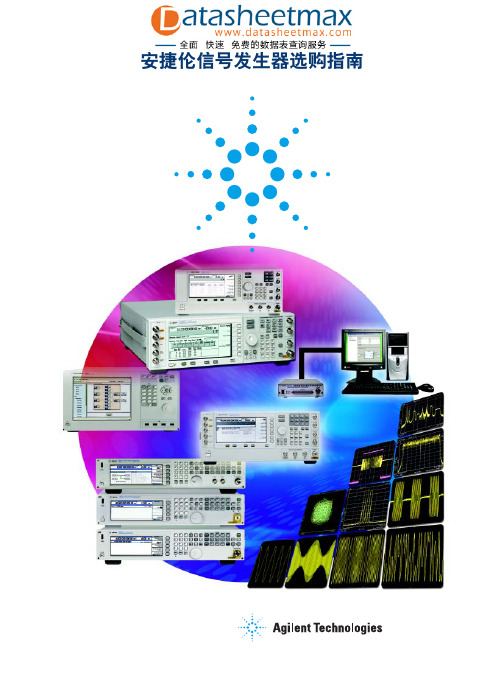
PSG 嵌入式软件 Signal Studio 软件
用户数据
I/Q 波形
Baseband generation tools
用于波形捕获和回放的 Baseband Studio 软件
用于衰落的 Baseband Studio 软件
I/Q 波形
RF/MW Signal Generation
模拟和数字 I/Q 信号
信号创建工具 (如 Signal Studio) 能够简化复杂信号的仿真过程。基带信 号生成工具 (如MXG配备的内部基带信号发生器) 将比特流转换为低频的IQ信 号,然后用 ESG,MXG 或 PSG 矢量信号发生器将 IQ 信号上变频为射频频率 或微波频率的信号。
Signal creation tools
Frequency coverage for Agilent spectrum and signal analyzers 9 kHz 1 GHz 3 GHz 6 GHz 9 GHz 40 GHz
67 GHz
2
安捷伦信号创建和生成模型
安捷伦信号生成方案包括三个主要部分: 信号创建,生成基带信号和生成 射频 / 微波信号。
安捷伦信号发生器选购指南
安捷伦信号发生器 — 为你量身定制测试解决方案
安捷伦信号发生器的优异性能和多种测量应用软件能让你在测试中更加自 信。安捷伦的信号源解决方案可以根据你的应用需求量身定制,用于研发,自 动化制造,便携式装置或设备维修。这篇选购指南纵向比较了不同信号源的性 能,可以帮你迅速找到最适合的安捷伦产品。
N9310A (9 kHz-3 GHz) N5181A/N5161A (100 kHz-6 GHz) E4428C (250 kHz-6 GHz) N5183A (100 kHz-40 GHz) E8257D (250 kHz-67 GHz) E8663D (100 kHz-9 GHz) N5182A/N5162A (100 kHz-6 GHz) E4438C (250 kHz-6 GHz) E8267D (250 kHz-44 GHz) N5106A 基带信号发生器
安捷伦GCMS培训资料

安捷伦GCMS培训资料一、GCMS 简介GCMS 即气相色谱质谱联用仪(Gas ChromatographyMass Spectrometry),是一种强大的分析仪器,结合了气相色谱的高效分离能力和质谱的高灵敏度、高选择性检测能力。
它在化学、环境、食品、医药等众多领域都有着广泛的应用。
安捷伦作为分析仪器领域的知名品牌,其 GCMS 产品具有卓越的性能和可靠性。
为了让大家更好地掌握和使用安捷伦 GCMS,以下将为您详细介绍其原理、操作及维护等方面的知识。
二、GCMS 原理气相色谱(GC)部分的原理是基于不同化合物在色谱柱中的保留时间差异,实现混合物的分离。
当样品被注入进样口后,会被气化并在载气的带动下进入色谱柱。
色谱柱内填充了固定相,化合物与固定相之间的相互作用不同,导致它们在柱中的移动速度不同,从而在不同时间被洗脱出来。
质谱(MS)部分则是通过将被分离的化合物离子化,并根据其质荷比(m/z)进行检测和分析。
离子化后的化合物在电场和磁场的作用下发生偏转,不同质荷比的离子到达检测器的时间和强度不同,形成质谱图。
GCMS 就是将气相色谱分离后的化合物依次引入质谱仪进行检测,通过对质谱图的分析,实现对化合物的定性和定量分析。
三、安捷伦 GCMS 仪器组成1、进样系统手动进样:适用于少量、不频繁的样品分析。
自动进样器:能实现大量样品的连续自动进样,提高工作效率和分析精度。
2、气相色谱系统色谱柱:有不同类型和规格,根据分析需求选择。
柱温箱:精确控制色谱柱的温度,以优化分离效果。
3、质谱系统离子源:常见的有电子轰击源(EI)和化学电离源(CI)等。
质量分析器:如四极杆、飞行时间等。
检测器:用于检测离子信号。
4、数据处理系统采集和处理分析数据,生成报告。
四、仪器操作流程1、开机前准备检查载气、电源等连接是否正常。
确保仪器内部清洁,无残留样品。
2、开机按照正确顺序开启仪器各部分电源。
等待仪器预热和自检完成。
3、方法设置选择合适的色谱柱和分析条件。
安捷伦及液相色谱仪的基本知识

安捷伦及液相色谱仪的基本知识集团标准化工作小组 [Q8QX9QT-X8QQB8Q8-NQ8QJ8-M8QMN]安捷伦1100液相色谱仪各项性能指标悬赏分:5|解决时间:2010-10-16 22:13|提问者:最佳答案朋友,直接致电agilent的800-820-3278免费电话就可以得到Agilent的满意答复了系列Agilent 1100泵系统● 电子流控阀(EFC)控制的毛细液相泵系统,精度高、流速范围广柱流速范围:1-20ul/min;10-100ul/min(可选件)-2.5mmin(EFC关闭状态)● 高压制备泵系统,单元或双元高压制备泵流速范围:min● 分析型泵系统流速范围:单元泵:min二元泵:min四元泵:min品种齐全的Agilent 1100系列进样系统● 标准手动进样器(分析型或制备型)● 标准自动进样器样品瓶容量:可达100个(2mlx100)进样量:可选件● 微盘式自动进样器样品瓶容量:2x96(孔板),2x386(孔板)或100x2ml进样量:(标准件)可选件● 微量标准自动进样器/微盘式自动进样器进样量:(标准);(可选)● 恒温标准自动进样器/微盘式自动进样器温度范围:4-40℃可设定步进1℃● 220型微孔板式自动进样器-组合化学样品管理系统样品瓶容量:各种规格试管多达12个微孔板(96孔板,384孔板)进样量:;Agilent 1100系列检测器● 可变波长扫描紫外检测器(VWD)波长范围:190600nm● 多波长检测器(MWD)波长范围:190950nm(双灯源)● 二极管阵列检测器(DAD)波长范围:190950nm(双灯源)● 荧光检测器(FID)激发波长:200-700nm;发射波长:280-900nm光谱存储:全光谱● 示差折光检测器(RID)温控:室温+5℃至55℃内置自动吹扫阀和自动溶剂循环阀● 电化学检测器(ECD)● LC/MS四极杆质量检测器(MSD)● LC/MS离子阱质量检测器(Trap MSD)柱温箱和脱气机组件● 柱温箱温度范围:室温下10℃至80℃可选件:柱切换阀● 真空在线脱气机安捷伦1120液相色谱仪技术参数泵:流速精度:≤% RSD流速范围:,以min的增量自动进样器:进样量范围:,以的增量进样精度:<% RSD(5-100ul),<1% RSD(1-5ul)样品容量:100个2ml样品瓶;或者2个半托盘,每个40个2ml样品瓶或15个6ml 样品瓶柱温箱:温控范围:室温上10℃到60℃温控稳定性:±0.15℃VWD:噪音:±×10 -5AU波长范围:190-600nm主要特点仪器介绍特点介绍可选5种配置系统,工厂测试,开箱即用和各种检测器兼容:示差折光检测器(RID),荧光检测器(FLD),蒸发光散色检测器(ELSD)易于使用的EZChrom Elite Compact软件,提供英中日界面LMD软件在故障发生前就可以实时通报新的最佳性能色谱柱提供可靠重现的结果附加服务:1120 液相色谱仪有五种集成的一体化配置可供选择:1.等度泵手动进样 VWD2.梯度泵手动进样 VWD3.梯度泵手动进样柱温箱 VWD4.梯度泵 ALS 柱温箱 VWD5.等度泵 ALS 柱温箱 VWD*其中包括了硬件、软件、色谱柱和LMD分析方法此仪器尚未上传分析方法相关资料1.安捷伦1120液相色谱仪详细技术参数与资料!!相关仪器液相色谱仪(1200)2.液相色谱仪LC2100(LC2100)相关耗材1.安捷伦C8、C18液相色谱柱(规格:C8、C18)2.安捷伦氘灯(规格:Agilent 1100)3.顶空进样瓶、自动进样瓶(规格:20ml)4.色谱微量进样器、液体进样器、气体进样器(规格:ul)5.安捷伦液相色谱住(规格:C8,C18)ZORBAX StableBond SB-C18液相色谱柱(规格:Agilent SB-C18)7.真空泵、无油真空抽滤泵(规格:QP-01)8.液相色谱柱温箱(规格:JK-LCagilent1200安捷伦液相色谱仪技术参数方便地利用四种溶剂进行等梯度或梯度分析,适用于方法快速开发和快速配备流动相,以及冲洗 HPLC 系统流量范围宽,最高流速 10 mL/min ,延迟体积 800-1100 L,适用于微径柱、标准柱和半制备应用通过 Instant Pilot 组件或安捷伦化学工作站或 EZChrom 软件,可以容易地进行编程和控制包含微量真空脱气机,脱气效率高,实现了操作无障碍和最高性能,完全不需要通氦气直接从前面板快速更换维护部件通过自我诊断、内置日志和预编程的测试方法,快速判断问题早期维护反馈(EMF)长期不间断地监测仪器使用和用户预设的限度,一旦超出限度,将提供反馈信息在所有安捷伦 1200 系列 HPLC 组件范围内可升级和扩展主要特点agilent1200安捷伦液相色谱仪特点介绍同时安捷伦1200系列快速高分离液相色谱系统同样和常规高效液相色谱仪一样耐用,也保留了常规液相色谱仪的方法和工作原理。
安捷伦频谱仪所有型号指南
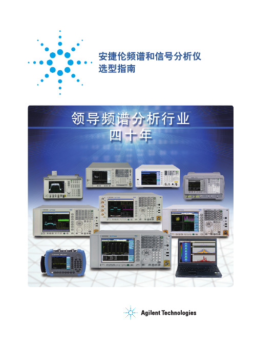
安捷伦频谱和信号分析仪选型指南引言安捷伦科技公司拥有全面的频谱分析仪和信号分析仪产品线,频率范围覆盖直流至 325G Hz,可对失真、杂散、相位噪声和无线通信信号的频率、幅度和调制进行精确测量。
这些仪器和 89600B 矢量信号分析(VSA)软件(一种灵活的调制分析软件或测量应用软件)结合使用后,可进一步扩展仪器功能,对广泛的标准数字信号和通用数字信号和格式进行解调。
购买信号分析仪器是一项重要投资。
购买的仪器不仅要满足当前的工作需求,而且要适应未来的要求。
鉴于每个项目和用户都有不同的需求,选择能够满足所有需求的最佳仪器可能会十分复杂且耗时,而时间就是金钱。
安捷伦作为全球领先的测试测量公司,可提供广泛的分析仪和应用软件,满足各个层次的预算需求。
本选型指南将帮助您轻松找到最适合您自身需求的频谱分析仪或信号分析仪。
产品定义频谱分析仪和信号分析仪传统意义上的频谱分析仪是指可提供幅度/频率显示、具备调谐扫描功能的超外差接收机。
当今分析仪具有调谐扫描功能和 FFT 体系结构。
尽管“频谱分析仪”和“信号分析仪”两个术语现在常常互换使用,但对于当今可进行全面频域、时域和调制域信号分析的分析仪来说,“信号分析仪”一词更为准确。
台式分析仪和手持式分析仪台式频谱/信号分析仪可提供优异的射频技术指标和测量应用软件。
而手持式频谱分析仪更被那些由于频谱空间日益拥挤、射频技术不断演进而需要花费大量时间在外场完成工作的射频工程师或技术人员所青睐。
为了解决他们所面临的难题,手持式频谱分析仪需要具备坚固、精确、快速且简单易用等特性。
测量应用软件和测量软件安捷伦提供了基于 PC 和基于仪器的应用软件,以满足从研发、故障诊断到一键完成制造测量的测试需求,这些软件适用于广泛的通信标准和调制类型。
EMI 和 EMC 解决方案电磁干扰(EMI)是由设备的辐射或传导发射造成的。
EMI 分析仪和接收机能够准确定位干扰源的频率和位置,从而减少或消除干扰信号。
安捷伦 E8257D 67D PSG 信号源用户指南说明书

用户指南E8257D/67D PSG 信号源本指南适用于下述型号的信号源:E8257D PSG 模拟信号源E8267D PSG 矢量信号源我们不断致力于通过修订固化软件和硬件改进我们的产品,因此信号源的设计和操作可能会与本指南中的说明有所不同。
我们建议您使用本指南的最新版本,以保证获得最新的产品信息。
您可以把本指南的日期(参见页底)与最新修订版进行比较,最新修订版可以从下述网站中下载:/find/psg制造部件编号: E8251-90363美国印刷2005 年 1月©2004-2014年安捷伦科技公司版权所有。
通告本文档中提供的材料并无保障,在未来版本中如有变更,恕不另行通告。
此外,在相应法律允许的最大范围内,安捷伦放弃与本手册及手册中涉及的任何安捷伦产品有关的所有明示保证或默示保证,包括但不限于适销性及适用于特定用途的默示保证。
对本文中的错误或由于提供、使用或实施本文档或任何相关安捷伦产品所导致的间接或直接损失,安捷伦概不负责。
如果安捷伦与用户签订了书面合同,且任何合同条款与本文相抵触,那么应以合同条款为准。
与我们的文档有关的问题或意见?欢迎提出与我们的文档有关的问题或意见,请通过电子邮件把这些问题或意见发送至:***********************.ii目录1.信号源概述 (1)信号源型号和主要特点 (2)E8257D PSG模拟信号源主要特点 (2)E8267D PSG矢量信号源主要特点 (4)选项 (5)固化软件升级 (5)为升级固化软件 (5)工作模式 (7)CW连续波模式 (7)扫描信号 (7)模拟调制 (7)数字调制 (7)前面板 (9)1. 显示屏 (10)2. 软键 (10)3. 旋钮 (10)4. Amplitude (幅度) (10)5. Frequency (频率) (10)6. Save (保存) (10)7. Recall (调用) (10)8. Trigger (触发) (11)9. MENUS (菜单) (11)10. Help (帮助) (11)11. EXT 1 INPUT (12)12. EXT 2 INPUT (12)13. LF OUTPUT (12)14. Mod On/Off (12)15. ALC INPUT (12)16. RF On/Off (13)17. 数字附加键盘 (13)18. RF OUTPUT (13)19. SYNC OUT (13)20. VIDEO OUT (13)21. Incr Set (13)22. GATE/ PULSE/ TRIGGER INPUT (14)23. 箭头键 (14)24. Hold (保持) (14)25. Return (返回) (14)iii目录26. Contrast Decrease (降低对比度) (14)27. Contrast Increase (提高对比度) (14)28. Local (14)29. Preset (预置) (14)30. 线路电源LED (14)31. LINE (15)32. 备用LED (15)33. SYMBOL SYNC (15)34. DATA CLOCK (15)35. DATA (16)36. Q Input (16)37. I Input (16)前面板显示屏 (17)1. 活动输入区域 (18)2. 频率区域 (18)3. 报警器 (18)4. 数字调制报警器 (20)5. 幅度区域 (20)6. 错误信息区域 (21)7. 文字区域 (21)8. 软键标签区域 (21)后面板 (22)1. EVENT 1 (24)2. EVENT 2 (24)3. PATTERN TRIG IN (24)4. BURST GATE IN (25)5. BASEBAND GEN REF IN (25)6. DIGITAL BUS (25)7. AUXILIARY I/O (26)8. WIDEBAND I INPUT (27)9. WIDEBAND Q INPUT (27)10. I OUT (27)11. Q OUT (27)12. I-bar OUT (27)13. Q-bar OUT (28)14. COH CARRIER (28)15. SOURCE MODULE INTERFACE (28)16. AC电源插座 (28)iv目录17. GPIB (29)18. 10 MHz EFC (29)19. 10 MHz IN (29)20. AUXILIARY INTERFACE (30)21. 10 MHz OUT (30)22. LAN (30)23. STOP SWEEP IN/OUT (31)24. Z-AXIS BLANK/MKRS (31)25. SWEEP OUT (31)26. TRIGGER OUT (31)27. TRIGGER IN (31)28. SOURCE SETTLED (32)29. RF OUT (32)30. EXT 1 Input (32)31. EXT 2 Input (32)32. LF OUT (32)33. PULSE SYNC OUT (32)34. PULSE VIDEO OUT (32)35. PULSE/TRIG GATE INPUT (32)36. ALC INPUT (33)37. DATA (33)38. DATA CLOCK (33)39. SYMBOL SYNC (33)40. I Input (33)41. Q Input (33)2 基本操作 (35)使用表格编辑器 (36)表格编辑器软键 (37)在数据字段中修改表格项目 (37)配置RF输出 (38)配置连续波RF输出 (38)配置扫描RF输出 (41)扩展频率范围 (56)调制信号 (57)打开调制格式 (57)对RF输出使用调制格式 (58)使用数据存储功能 (59)v目录使用内存目录 (59)使用仪器状态寄存器 (61)使用安全功能 (64)理解PSG内存类型 (64)从PSG内存中删除敏感的数据 (68)使用安全显示 (70)启动选项 (71)启动软件选项 (71)使用网络服务器 (73)激活网络服务器 (73)3 基本数字操作 (77)定制调制 (78)定制任意波形发生器 (78)定制实时I/Q基带 (79)任意(ARB)波形文件标题 (80)为调制格式波形创建文件标题 (81)修改调制格式中的标题信息 (82)为双ARB播放器波形序列存储标题信息 (87)修改和查看双ARB播放器中的标题信息 (87)播放包含标题的波形文件 (90)使用双ARB波形播放器 (91)访问双ARB播放器 (91)创建波形段 (92)构建和存储波形序列 (93)播放波形 (94)编辑波形序列 (94)在双ARB波形中增加实时噪声 (95)存储和加载波形段 (96)重新命名波形段 (96)使用波形标尺 (97)波形标尺的概念 (98)访问标尺辅助工具 (102)查看波形段标尺 (103)1. 从波形段中清除标尺点 (104)2. 在波形段中设置标尺点 (105)3. 控制波形序列中的标尺(仅适用于双ARB) (108)查看标尺脉冲 (110)vi目录使用RF消隐标尺功能 (111)设置标尺极性 (112)触发波形 (113)信号源 (113)模式和响应 (114)使用触发辅助工具 (115)设置外部触发器的极性 (115)使用选通触发 (116)使用Segment Advance触发 (118)使用波形削波 (119)功率峰值怎样发展 (119)峰值怎样导致频谱再生 (121)削波怎样降低峰值均值功率比 (122)配置圆形削波 (125)配置矩形削波 (126)使用波形定标 (127)DAC超出额定范围错误是怎样发生的 (127)定标怎样消除DAC超出额定范围错误 (128)定标目前正在播放的波形(运行时定标) (129)在易失性内存中定标波形文件 (129)4 优化性能 (131)使用ALC (132)选择ALC带宽 (132)为选择ALC带宽 (132)优化突发的ARB信号的电平精度 (133)使用外部置平 (135)使用检测器和耦合器/分路器进行置平 (135)使用选项1E1信号源进行外部置平 (138)创建和应用用户平坦度校正 (139)创建用户平坦度校正阵列 (139)使用毫米波信号源模块创建用户平坦度校正列 (144)调节参考频率振荡器带宽(选项UNR) (151)选择参考频率振荡器带宽 (151)恢复出厂默认设置: (151)5 模拟调制 (153)模拟调制波形 (154)vii目录配置AM (选项UNT) (155)设置载频 (155)设置RF输出幅度 (155)设置AM深度和速率 (155)启动幅度调制 (155)配置FM (选项UNT) (156)设置RF输出频率 (156)设置RF输出幅度 (156)设置FM偏差和速率 (156)激活FM (156)配置ΦM (选项UNT) (157)设置RF输出频率 (157)设置RF输出幅度 (157)设置ΦM偏差和速率 (157)为实现ΦM (157)配置脉冲调制(选项UNU/UNW) (158)设置RF输出频率 (158)设置RF输出幅度 (158)设置脉冲周期、宽度和触发 (158)激活脉冲调制 (158)配置LF输出(选项UNT) (159)使用内部调制源配置LF输出 (160)使用函数发生器来源配置LF输出 (161)6 定制任意波形发生器 (163)概述 (164)处理预先定义的设置(模式) (165)选择定制ARB设置或定制数字调制状态 (165)处理用户定义的设置(模式)-仅定制ARB (166)修改单载波NADC设置 (166)定制多载波设置 (167)调用用户定义的定制数字调制状态 (168)处理滤波器 (169)预先定义的滤波器(Filter > Select) (170)使用预先定义的FIR滤波器 (171)处理码速率 (177)设置码速率 (177)恢复默认码速率(仅定制实时I/Q) (177)viii目录处理调制类型 (180)选择预先定义的调制类型 (180)使用用户定义的调制类型(仅实时I/Q) (181)宽带IQ (选项015) (187)配置硬件 (188)设置延迟正极外部单触发 (188)设置ARB参考 (189)7 定制实时I/Q基带 (191)概述 (192)处理预先定义的设置(模式) (192)选择预先定义的实时调制设置 (192)反选预先定义的实时调制设置 (192)处理数据码型 (193)使用预先定义的数据码型 (194)使用用户定义的数据码型 (195)使用外部提供的数据码型 (198)处理突发形状 (199)配置突发上升和下降参数 (200)使用用户定义的突发形状曲线 (201)配置硬件 (204)设置BBG参考频率 (204)设置外部DATA CLOCK作为正常输入或码输入接收输入 (205)把BBG DATA CLOCK设成External或Internal (205)调节I/Q标度 (205)处理相位极性 (206)把相位极性设为正常或反相 (206)处理差分数据编码 (207)了解差分编码 (207)使用差分编码 (212)8 多音波形发生器 (215)概述 (216)创建、查看和优化多音波形 (217)创建定制多音波形 (217)查看多音波形 (218)编辑多音设置表 (219)ix目录使载波馈通达到最小 (221)确定峰值均值比特点 (223)9 双音波形发生器 (225)概述 (226)创建、查看和修改双音波形 (227)创建双音波形 (227)查看双音波形 (228)使载波馈通达到最小 (230)改变双音波形的对齐方式 (232)10 AWGN波形发生器 (233)配置AWGN发生器 (234)任意波形发生器AWGN (234)实时I/Q基带AWGN (235)11 外围设备 (237)N5102A数字信号接口模块 (238)时钟定时 (238)连接时钟源和被测器件 (250)数据类型 (252)以输出模式操作N5102A模块 (253)以输入模式操作N5102A模块 (262)毫米波信号源模块 (272)使用安捷伦毫米波信号源模块 (272)使用其它信号源模块 (275)12 问题诊断 (279)RF输出功率问题 (280)在播放波形文件时没有RF输出功率 (280)RF输出功率太低 (280)电源已经关闭 (281)在使用混频器时信号丢失 (281)在使用频谱分析仪时信号丢失 (282)RF输出上没有调制 (284)扫描问题 (285)扫描似乎停止了 (285)不能关闭扫描模式 (286)x目录列表扫描驻留时间值不正确 (286)调用的寄存器中列表扫描信息丢失 (286)数据存储问题 (287)以前存储仪器状态的寄存器是空的 (287)已经保存了仪器状态,但寄存器是空的或包含错误状态 (287)不能打开帮助模式 (288)信号源锁住 (289)故障自动防护恢复顺序 (289)错误信息 (291)错误信息文件 (291)错误信息的格式 (292)错误信息的类型 (293)联系安捷伦销售和服务办事处 (294)把信号源退回安捷伦 (295)xi目录xii1 信号源概述本章将在下面几节中介绍安捷伦PSG信号源的型号、选项和主要特点,另外还将介绍其工作模式、前面板用户接口及前面板和后面板连接器。
02 安捷伦7820A产品和应用介绍

输入 / 输出
•输入报告
•可以直接读取 Chemstation, Turbo Chrom and Thermo中的谱图, 也可以读取 ASCII and .CDF 文件
•输入样品序列
•可以用其他程序编写序列 •Elite可以直接读取序列
•数据输出
•所有数据都是以 ASCII or CDF文件格式保存 •报告格式 为ASCII
ECD高灵敏度保证有机氯杀虫剂在0.5 g/L痕量水平有非常高的信噪比
Page 38
饮用水中有机氯杀虫剂分析
1. -BHC 2. Lindane 3. -BHC 4. -BHC 5. p,p’-DDE 6. o,p’-DDT 7. p,p’-DDD 8. p,p’-DDT
Hz
饮用水中加入10ppb的杀虫剂
1
2000 1800 1600 1400 1200 1000 800 600 400 200 0 2 4 6 8 10
2
4 5 6 7 8
3
12
14
16
18
20
22
24
26
28
30
32
Min
Sample size: 1uL, Splitless Oven temperature program: 50 °C (3 min); 30 °C/min to 210 °C (30min)
安捷伦品质——立足于设计
• 7820气相色谱仪在设计阶段历经了3600小时58项严酷的测试,其中 涵盖了电子,机械,化学,气体压力和爆炸伤害。
50倍重力加速度的冲击测试
爆炸试验
严酷的测试
辐射发射测试
包装测试
振动测试
温、湿度测试
信号源使用注意事项
信号源使用注意事项容易造成信号源损坏的几条原因:一:静电静电会产生瞬时高达几万伏的电压,对电子元器件有着致命的伤害。
信号源中的衰减器和混频器对其极为敏感,容易被其打坏。
所以在使用信号源时,应注意静电防护。
值得一提的是,有些静电人体并未能感知得到,但足以对仪器造成损坏。
A,任何仪器在使用过程中,必需保证接地B,仪器操作人员应穿静电服,防静电鞋,手戴防静电手环。
并在每次使用仪器测试其防静电装备是否良好。
C,被测产品在测试前应先充分放电。
二:信号源输出功率不能太大。
经常地超负荷输出信号对信号源有不良的影响,会降低信号源的使用寿命。
安捷伦的信号源在不同型号和不同选件的情况下,最大输出功率各有不同。
因此在使用信号源时,因熟读此型号信号源的Data Sheet.。
在Data Sheet中所给出的功率输出范围内使用仪器。
三:在测试有源器件,如放大器时。
信号源输出端必须加反向功率保护,在射频电缆未拧紧时,不要按输出键。
A注意阻抗匹配。
如果阻抗匹配不好,由此引起的反射信号将直接进入到信号源内部的反向保护电路,对反向保护电路形成冲击。
冲击越频繁,使方向保护电路更加加速老化。
正确的设定输出功率值以及良好的阻抗匹配可以延缓器件的老化,降低故障率。
B在测试大功率的直放站时,将存在反向大功率,在信号源输出端必须加功率衰减器。
如Agilent8491Bb-20dBAttenuator等。
四:如初测器件会产生直流偏置,测信号源输出端需加隔直器。
直流偏置进入信号源的输出端后,会对信号源的反向功率保护电路产生影响。
降低使用帮命。
隔直器型号如:AgilentN9398C/F/G., N9399C/F等。
五:机械应力。
在信号源输出端,不能加持重物(如大功率衰减器等)六:保持良好的使用环境。
良好的接地,通风和散热是延长信号源使用寿命的必要条件。
A,安捷伦的仪器使用电环境需达到安捷伦对供电电源质量的要求标准。
类似于国家计算机房A类标准。
B,要定期清洁信号源的出风口,保证没有灰尘阻挡仪器的散热。
Agilent 81110A 数字信号源数据手册说明书
Agilent 81110A Agilent 81100 Family ofPulse Pattern GeneratorsData Sheet – Version 1.3Flexible Pulses or Patterns for DigitalDesigns – Key Features• Pattern mode on all models from 80 MHz to 660 MHz,including pseudo-random binary sequence• The outputs of dual-channel instruments can be added(analog or EXOR, depending on model)• User-retrofittable channels for most models• Upward compatibility• Individual solutions for frequencies up to 50, 80, 165, 330, 400 and 660 MHz• 100% form/fit compatibilitySignals for testing digital designs and componentsThe Agilent 81101A, 81104A, 81110A and 81130A generate all the standard pulses and digital patterns needed to test current logic technologies (CMOS, TTL, LVDS, ECL, etc.).With the optional second channel on all of the models from 80 MHz to 660 MHz, multi-level and multi-timing signals can be obtained using the internal channel addition feature.• Variable pulse parameters in pattern mode as well as in pulse mode (not on the 81130A)• Synchronously triggerable• Simulation of reflections/distortions• (81104A, 81110A)• Three/four-level codes (81104A, 81110A)Glitch-free timing changesTiming values can now be swept without the danger of misleading pulses ordropouts that could cause measurement errors. (Applies to continuous mode, values < 100 ms, consecutive values between 0.5 and twice the previous value on the 81101A, 81104A, 81110A).Reliable measurementsAll models provide clean, accurate pulses with excellent repeatability, thus contribut-ing to measurement integrity.The Agilent 81110A features self-calibration for more accuracy. It also offers a choice of output modules. The Agilent 81111A 165 MHz 10 V module with variable transitions.Along with the Agilent 81112A 330 MHz 3.8 V module, which has differential out-puts and two selectable transition times.The Agilent 81130A offers a choice of output modules: the Agilent 81131A 400 MHz, 3.8 V module and the Agilent 81132A 660 MHz, 2.5 V module which has complementary outputs.Easy-to-useFeatures such as the clear graphicaldisplay, autoset, help, store/recall, preset TTL/ECL levels, selectable units (such as current/voltage, width/duty-cycle), and load compensation ensure a high level of convenience.Stimulate the device’s environmentToday’s devices can require very complex stimuli. To meet this, the Agilent 81130A can sequence and loop its memory for very deep patterns. RZ (return-to-zero), NRZ (non-return-to- zero) and R1 (return-to-one) formats are available. Digital channel addition allows the generation of signals with two different pulse widths and delays or of data rates up to 1.32 Gbit/s in one single channel.Frequency rangeThe Agilent 81130A is designed and recommended for an operation in the frequency range of 170 kHz to 400/660 MHz. However it can be operated in the extended range down to 1 kHz.Data Sheet 81100 Family of Pulse Pattern Generators21. Depends on selected impedance (all other values for 50 Ω source impedance into 50 Ω load).2. 0.001% +15 ps with internal PLL as clock source.3. Also avalable as VXI pulse pattern generators E8311A and E8312A.Agilent 81100 - Family of Pulse Pattern Generators81101A SpecificationsBurst Count : 2 to 65536 (single or double pulses).Delay : Delay, phase or % of period.Double pulse delay : Double pulse and delay are mutually exclusive.Duty cycle : Set between 0.1% and 95% (subject to width limits. 99.9% with overprogramming).Transition times: These can be entered as leading/trailing edge or % of width. Leading and trailing edges are indepen-dent within one of the following over-lapping segments (1:20 ratio):• 5 ns - 20 ns • 10 ns - 200 ns • 100 ns - 2 µs • 1µs - 20 µs • 10 µs - 200 µs • 100 µs - 2 ms • 1 ms - 20 ms •10 ms - 200 msData Sheet 81100 Family of Pulse Pattern Generators3Repeatability : Is typically four times better than accuracyOutput timing fidelity : Period, delay and width are continuously variable without any output glitches or dropouts.Data Sheet 81100 Family of Pulse Pattern GeneratorsTrigger modesContinuous : Continuous pulses, double pulses or bursts (single or double pulses).External triggered : Each active inputtransition (rising, falling or both) generates a single or double pulse or burst.External gated : The active input level (high or low) enables pulses, double pulses or bursts. The last single/double pulse or burst is always completed.External width : The pulse shape can be recovered whilst the period and width of an external input signal are maintained. Levels and transitions can be set.Manual : Simulates an external input signal.Internal triggered : Internal PLL replaces an external trigger source.Inputs and outputsClock input/PLL reference and external input: One input (BNC connector at rear panel) is used for clock input or alterna-tively for the PLL.PLL reference : The internal PLL is locked to an external 5 MHz or 10 MHz reference frequency.Clock input : The output period isdetermined by the signal at CLK input. Ext. input : Used for trigger, gate or external width.Level parameters: Can be entered as volt-age or current, as high and low level, or as offset and amplitude.Load compensation:The actual load value can be entered (for loads ≠ 50 Ω) to display actual output values. On/off: Relays connect/disconnect output (HiZ).Normal/complement: Selectable.Limit : Programmable high and low levels can be limited to protect the device-under-test.Input impedance : 50 Ω/10 kΩ selectable.Threshold : -10 V to +10 V.Max. input voltage : ±15 Vpp.Sensitivity : 300 mVpp typical.Input transitions : < 100 ns.Frequency : Dc to 50 MHz.Minimum pulse width : 10 nsStrobe output and trigger output trigger format : One pulse per period with 50% duty cycle typical.External mode : 9 ns typ.Level : TTL or ECL selectable.Output impedance : 50 Ω typical.Max. external voltage : -2 V/+7 V.Transition times : 1.0 ns typical for TTL, 600 ps typical for ECL.41. In ±19 V level window81104A and 81110A SpecificationsBurst count: 2 to 65536 (single or double pulses).Delay : Delay, phase or % of period.Double pulse and delay : Mutually exclusive.Duty cycle : Set between 0.1% and 95% (subject to width limits. 99.9% with over-programming).Repeatability : Is typ. four times better than accuracy.Transition times : leading/ trailing edge or % of width. Leading and trailing edges are independent Agilent 81111A/Agilent 81105A) within one of the following overlapping segments (1:20 ratio): • 2 ns (3 ns) - 20 ns • 10 ns - 200 ns • 100 ns - 2 ms • 1µs - 20 µs • 10 µs - 200 µs • 100 µs - 2 ms • 1 ms - 20 ms •10 ms - 200 msOutput timing fidelity : Period, delay and width are continuously variable without any output glitches or dropouts.Overprogramming : All parameters of the Agilent 81110A, except transitions, can be set to whatever the 330 MHz timing system will allow. This applies also when the Agilent 81111A (165 MHz) output module is used.Data Sheet 81100 Family of Pulse Pattern Generators51. Source impedance is selectable from 50 Ω to 1 KΩ for the Agilent 81111A.2. Changing of amplitude may add 0.5 ns.Level/Pulse Performance CharacteristicsLevel parameters: voltage or current, high or low level, offset or amplitude.On/off: relays connect/ disconnect output (HiZ).Load compensation: the actual load value can be entered (forloads ≠ 50 Ω) to display actual output values. (Applies to theAgilent 81105A and Agilent 81111A only).Normal/complement: selectable.Limit: programmable high and low levels can be limited to protect the device-under-test.Channel Addition (with Agilent 81105A or Agilent 81111A output channels)If the instrument is equipped with 2 output modules, channel 2 can be added to channel 1 internally. In this case the second output is disabled. The additional fixed delay on the second channel is typ. 2.5 ns. The following parameters differ from the above specifications if two output modules (Agilent 81105A/Agilent 81111A) are added.Data Sheet 81100 Family of Pulse Pattern Generators61. In ± 19 V level window.Pattern modePattern length: 16 kbit/channel and strobe output.Output format: RZ (return to zero), NRZ (non-return to zero), DNRZ (delayednon-return to zero).Random pattern:PRBS 2 ^ (n - 1) n = 7,8, (14)Trigger modesContinuous: Continuous pulses, double pulses, bursts (single or double pulses)or patterns.External triggered: Each active input transition (rising, falling or both) generates a single or double pulse,burst or pattern.External gated: The active input level (high or low) enables pulses, double pulses, bursts or patterns. The last single/double pulse, burst or patternis always completed.External width: The pulse shape can be recovered. Period and width of an external input signal is maintained. Delay, levels and transitions can be set.Manual: Simulates an external input signal.Internal triggered: Internal PLL replaces an external trigger source. Pulses, double pulses, bursts or patterns can be set.Strobe output and trigger outputStrobe output: User-defined, 16 kbitpattern (NRZ) when in pattern mode.Trigger format: One pulse per period with50% duty cycle typical. External mode:1.5 ns typ. for Agilent 81110A. 5.9 ns typ.for Agilent 81104A.Level: TTL or ECL selectable.Output impedance: 50 Ω typical.Max. external voltage: - 2 V/+7 V.Transition times: 1.0 ns typical for TTL,600 ps typical for ECL.Inputs and OutputsClock input/PLL reference andexternal inputPLL reference: (BNC connector at rearpanel). The internal PLL is locked to anexternal 5 MHz or 10 MHz referencefrequency.Clock input: (BNC connector at rearpanel). The output period is determinedby the signal at CLK input.Ext. input: Used for trigger, gate orexternal width.Input impedance: 50 Ω/10 kΩ selectable.Threshold: - 10 V to + 10 V.Max. input voltage: ± 15 Vpp.Sensitivity: ≤ 300 mVpp typical.Transitions: < 100 ns.Frequency: dc to max. frequencyof output module.Min. pulse width: 1.5 ns (as width ofoutput module in external width mode).711. Subtract 4 ns from the typ. delay value when referring to OUTPUT 1 / 2 for the Agilent 81112A output module and add 1 ns when referring toOUTPUT 1 / 2 for the Agilent 81104A with the Agilent 81105A output module.Data Sheet 81100 Family of Pulse Pattern GeneratorsData Sheet 81100 Family of Pulse Pattern Generators8Burst count : 2 to 65504.Delay : Delay, phase or % of period.Duty cycle : Set between 0.1% and 99,9% (subject to width limits).Repeatability : Is typ. four times better than accuracy.1. The uncertainty of 1 period can be eliminated if an external clock and the following setup and hold times are upheld. setup time: 0.3 ns to 4.3 ns; hold time: -2.8 ns to 4.0 ns.Data Sheet 81100 Family of Pulse Pattern GeneratorsSequencing : A sequence is a succession of segments. One outer loop running once or continuous, and one nested loop can be applied. The nested loop can be set from 1 to 2 ^ 20 repetitions.Segment : The memory can be divided into maximal 4 segments.Segment length resolution : This is the resolution for which the segment can be set dependent on the maximum data rate. See Table 1.Limit : Programmable high and low levels can be limited to protect the device-under-test.Segment types: Pattern, PRBS, high and low segments ( “0” or “1” levels segments selectable).Note : If one channel is set to PRBS the other channel can only be high or low segments, or PRBS type.Random pattern : PRBS 2 ^ n - 1,n = 7,8,...,15 (CCITT 0.151).Level parameters : Voltage or current, high and low level, or offset and amplitude.Pattern and sequencingPattern length: 65504 bit/channel. If PRBS is used: (65503-RBLength).Pattern formats : NRZ (non-return-to-zero), DNRZ (delayed non-return-to-zero), RZ (return-to-zero) and R1 (return-to-one) can be selected (see Figure 1).On/off : Relays connect/disconnect output (HiZ).9Segment length resolution trade-offs1. The minimum length in the first segment of a nestedloop is two times that of the segment length resolution.Width is a multiple of clock periods.Width and delay can be set as required.Width and delay can be set as required.The signal can be delayed as required.Output pattern formats Non-return-to-zeroR1RZ DNRZNRZReturn-to-oneReturn-to-zero Delayed non-return-to-zeroData Sheet 81100 Family of Pulse Pattern GeneratorsTrigger modesContinuous : Continuous pulses, bursts or patterns.External started : Each active input transi-tion (rising, falling edge) generates pulses, bursts or patterns.External gated : The active input level (high or low) enables pulses, bursts or patterns. On an external gate signal the output is immediately stopped, that means the last cycle will not be completed.Manual : Simulates an external input signal with push of a front panel button.Inputs and outputsClock input/PLL reference and external inputConnectors : SMA (f) 3.5 mm Input impedance : 50 ΩTermination voltage : -2.10 V to 3.30 V Input sensitivity : < 400 mV typ.Max. input voltage : -3 V to + 6 V Input transitions : < 20 nsOnly valid for clock input/PLL reference One input is used for clock input or for the PLL reference alternatively.Reference : The internal PLL is locked to the 1,2,5 or 10 MHz. The output frequency of the instrument must be larger than the clock input/PLL reference frequency.External clock : The output period is determined by the signal at clock input. Clock input frequency : 170 kHz to 660 MHz (at 50% ±10% duty cycle).Delay from input trigger output : 21 ns.Delay from input to output : 53 ns.Threshold : ac coupled. Only valid for external input.External input : Used for external started or gated.Input frequency : DC to 330MHz.Delay from external input to trigger output : 22ns + 0 to 1 period.Delay from external input to output : 54 ns + 0 to 1 period.Threshold : -1.4 V to +3.7 V.Trigger outputTrigger format : One pulse per period with 50% duty cycle typical. In pattern mode the trigger pulse can be set to mark the start of any segment.Output impedance : 50 Ω typical.Level : TTL/ETTL (for frequency < 180 MHz), 1 V to GND, ECL 50 Ω to GND/-2 V, PECL 50 Ω to + 3 V.Max. external voltage : -2 V/+3 V.Transition times : 1.0 ns typical for TTL, 600 ps typical for ECL.Delay from external input to trigger output : 32 ns typical.Channel 1 +Figure 2: Channel addition10Programming times: (measured at display off)1. Range depends on segment length resolution, see previous table.Data Sheet 81100 Family of Pulse Pattern Generators11Ordering Information - 81100 FamilyThe minimum configuration for a working instrument consists of a mainframe and one output module. The second output module can be added later. Output modules can be exchanged and retrofitted by the user. The Reference Guide (811xx-91021) is supplied with each mainframe for all configurations. A memory card is not included.Each Agilent 81101A mainframe includes one output channel (in comparison to the other models of the Agilent 81100 family). The output module of the 81101A does not need to be ordered separately.Agilent 81101A50 MHz one channel pulse generator, 10 V Quick start guide language options Opt OBI Engish Guide(811xx-91021)Opt ABF French Guide(81101-91210)Opt ABJ Japanese Guide(81101-91510)Opt AB0Taiwan Chinese Guide(81101-91610)Opt AB1Korean Guide(81101-91710)Opt AB2Chinese Guide(81101-91810)Additional documentation optionsOpt 0BW Service Manual(81101-91021)Agilent 81104A80 MHz pulse/pattern generatormainframeOutput module:Agilent 81105A 80 MHz, 10 VAgilent 81110A330/165 MHz pulse/pattern generatormainframeOutput modules:Agilent 81111A 165 MHz, 10 VAgilent 81112A 330 MHz, 3.8 VNote: Only use output modules of thesame module number. A combination ofthe Agilent 81111A and Agilent 81112A inone Agilent 81110A is not possible.Quick start guide language optionsOpt OBI Engish Guide(811xx-91021)Opt ABF French Guide(81110-91210)Opt ABJ Japanese Guide(81110-91510)Opt AB0 Taiwan Chinese Guide(81110-91610)Opt AB1Korean Guide(81110-91710)Opt AB2 Chinese Guide(81110-91810)Additional documentation optionsOpt 0BW Service Manual(81110-91021)Agilent 81130A400/660 MHz pulse/data generatormainframeOutput modules:Agilent 81131A 400 MHz, 3.8 VAgilent 81132A 660 MHz, 2.4 VNote: Only use output modules of thesame module number. A combination ofthe Agilent 81131A and Agilent 81132A inone Agilent 81130A is not possible.Quick start guide language optionsOpt OBI Engish Guide(811xx-91021)Opt ABF French Guide(81130-91220)Opt ABJ Japanese Guide(81130-91520)Opt AB0Taiwan Chinese Guide(81130-91620)Opt AB1Korean Guide(81130-91720)Opt AB2Chinese Guide(81130-91820)Additional documentation optionsOpt 0BW Service Manual(81130-91021)Opt 0B1English Quick StartGuide (includes EnglishRef eremceGuide)Opt ABJ Japanese Quick StartGuide (includes EnglishRef erecnceGuide)Opt 0B0 Does not include anyQuick Start Guide(includes EnglishReferenceGuide)All options are orderable with themainframes.AccessoriesOpt UN2Rear panel connectors (insteadof front panel)Opt 1CP Rack mount and handle kit(5063-9219)Opt 1CN Handle kit (5063-9226)Opt 1CM Rack mount kit (5063-9212)Opt 1CR Rack slide kit (1494-0059)Opt UFJ 1 MB SRAM memory card(0950-3380)Opt UK6Commercial cal. certificate withtestdataData Sheet 81100 Family of Pulse Pattern Generators 12Product specifications and descriptions in this document subject to change without notice.© Agilent Technologies, Inc. 2009Printed in USA, November 24, 20095980-1215E。
安捷伦信号源、分析仪选件说明
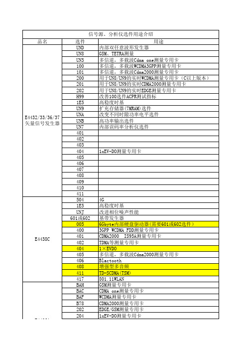
EDGE实时测量专用卡:需要UD8和UN9选件支持
频率范围:250KHz~3GHz
35 MHz RF调制带宽
双任意波形发生器和实时I/Q基带发生器
40 MHz 采样数率和14位的I/Q精度
1 M (4 MB) 采样内存 用来回放波形及1M (4 MB) 采样内存用于波形 存储 自定义调制方式 (>15 variations of FSK, MSK, PSK, and QAM), AM, FM, phase modulation, pulse modulation, and step/list sweep (frequency and power)
品名
E4432/33/36/37 矢量信号发生器
E4438C
E4406A 发射机 测量仪
信号源、分析仪选件用途介绍
选件 UND UN8 UN5 100 101 200 201 202 H99 1E5 UN9 UNA UNB UN7 401 402 403 404 405 406 407 408 409 410 411 504 1E5 UNJ 601或602 005 400 401 402 404 405 406 408 411 417 BAH BAC BAF B78 202
Model #-1CP Adds rack mount kit with handles, part number 5063-9221 Model #-1CP带手柄的机架安装工具包,零件号5063-9221
Model #-1E5 Adds high-stability timebase Model #-1E5高稳度时基 Model #-1E6 High-performance pulse modulation Model #-1E6 高精度的脉冲调制功能 Model #-1EM Moves all front panel connectors to rear panelModel #-1EM将前面板连接器移到后面板 Model #-UN5 Adds multichannel IS-95 CDMA personality Model #-UN5 增加多信道的IS-95 CDMA的专用卡 Model #-UN7 Adds internal bit-error-rate analyzer Model #-UN7增加内部误码率分析仪
安捷伦产品手册
7697A 顶空进样器 —— 具有 111 位和 12 位样品瓶容量两种配置的最先进顶空气相色谱系统,在序列运行 过程中可以更换样品盘,从而提高样品通量
欢迎您的选购 如果您想了解安捷伦生命科学和应用市场的全部产品系列,请访问
如需订阅或下载《安捷伦色谱与光谱产品目录中文版》,请访问 /chem/catalog-cn
目录 气相色谱 ...........................................................................................................................................................3
4
/chem/lc-cn
安捷伦液相色谱
无限卓越的 UHPLC 解决方案 —— 满足所有应用和预算需求
1290 Infinity II LC
1260 Infinity LC
1220 Infinity LC
1290 Infinity II 液相色谱系统 —— 引领了 UHPLC 的未来趋势 — 具有极高的稳定性和耐用性,辅以突破性的技术,从三方面大幅提高您的业务 效率:最大化分析效率 、最大化仪器效率 、最大化实验室效率 1260 Infinity 液相色谱系统 —— 建立了更高的性能标准和可信度。同时还提供了 UHPLC 水平的分析效率、数据质量和耐用性 —— 价格却仅仅 相当于普通的 HPLC 系统 1220 Infinity 液相色谱系统 —— 用于常规 HPLC 和先进的 UHPLC 分析的高质量集成系统,使您的投资回报最大,配合移动设备平台附件,1220 Infinity 可立刻升级成为车载液相色谱仪;构建移动实验室
安捷伦介绍

光示波器
多波长计
SONET Trib signals
STS & VT Switch Matrix
N2X XM (Sonet/SDH Cards)
传输分析仪
数据协议分析仪
Haiyang HU
内容安排
•光通信常用仪表 •光通信仪表计量方法 •安捷伦在计量上的方案和特点 •安捷伦光通信新仪表及方案
Haiyang HU
Haiyang HU
1
安捷伦科技在中国
2003 1985 1997
中国惠普 HP-软件科技园 安捷伦中国 2000 通信业务部门 安捷伦实验室 (CCO)
2005
安捷伦控股 安捷伦-前锋(CID)
1995
安捷伦上海 化学分析测试 产品工厂 (ASA)
1999
安捷伦中国 软件中心
2001
安捷伦上海 (ATS)
6
Haiyang HU
建立怎样的光通信仪表计量系统
1. 为正确地校准仪器,应根据推荐的程序执行制造商说明的所有测试。 2. 其中部分测试非常简易,任何人只需最少的投资就可以执行测试。 3. 简易测试: • 需要时间短 • 不要求昂贵的专用测试设备 4. 某些项目,如DMM只需简易测试,因此任何人都可以正确校准。比较复杂的产 品,如光谱分析仪,则同时包括简易测试和困难测试。 5. 困难测试则需要大量的成本。您将需要进行大量投资,以完成困难测试。许多 困难测试需要很长时间才能完成 (有时需要几个小时)。
简易测试 需要时间短, 不需要专用设备
困难测试 需要时间长
困难测试 需要专用设备
Haiyang HU
8
如何定位校准测试类型?
实例:光谱分析仪校准
简易测试 需要时间短, 不需要专用设备
Agilent E5052A 信号源分析仪数据手册说明书
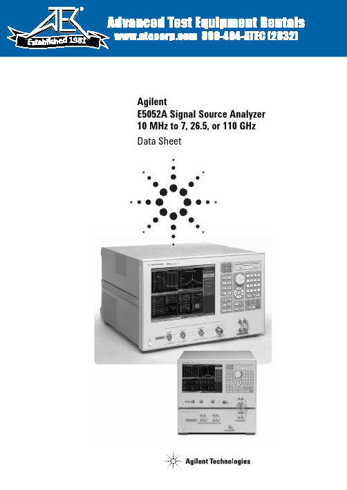
1981AgilentE5052A Signal Source Analyzer10 MHz to 7, 26.5, or 110 GHzData SheetDefinitionsAll specifications apply over a 18 °C to 28 °C range (unless otherwise stated) and 30 minutes afterthe instrument has been turned on. All specified and supplemental values for RF input signals are applicable to sinusoidal-wave carriers unless otherwise noted.Supplemental information is intended to provide information that is helpful for using the instrument but that is not guaranteed by the product warranty. This information is denoted as either typical or nominal.Specification (spec.): Warranted performance. Specifications include guardbands to account for the expected statistical performance distribution, measurement uncertainties, and changes in performance due to environmental conditions.Typical (typ.): Expected performance of an average unit that does not include guardbands. It is not guaranteed by the product warranty.Nominal (nom.): A general, descriptive term that does not imply a level of performance. It is not guaranteed by the product warranty.24Figure1-4. SSB phase noise sensitivity of different LO optimization(typical)( standard, correlation = 1, carrier frequency = 1 GHz, startoffset frequency = 1 Hz, +5 dBm input, measurement time = 17.7 sec) Figure1-2. SSB phase noise sensitivity (E5052A-011, typical)(standard, < 150 kHz optim., +5 dBm input, start offset frequency= 10 Hz, measurement time = 4.4 sec)Figure1-3. SSB phase noise sensitivity improved with the cross-correlation function (typical) (standard, improvement with thecorrelation, carrier frequency = 1 GHz, < 150 kHz optim., +5 dBm input) Figure1-1. SSB phase noise sensitivity (typical)(standard, < 150 kHz optim., correlation = 1, +5 dBm input,start offset frequency = 1 Hz, measurement time = 17.7 sec)53. When a DUT’s frequency is settled to a selected target frequency.6Table 1-15. Narrow band transient (frequency bandwidth = 3.125 kHz)Measurement time (sec)100 m200 m500 m12510Frequency resolution (Hz rms)0.00950.00950.00340.00120.00040.00040.0004Time resolution (µsec)81.92163.84409.6819.21638.4409610240Number of point122212221222122212221222978Table 1-16. Narrow band transient (frequency bandwidth = 25 kHz)Measurement time (sec)10 m20 m50 m100 m200 m500 m12510 Frequency resolution (Hz rms)0.220.220.0760.0270.00950.00950.00950.00950.00950.0095 Time resolution (µsec)10.2420.4851.2102.4204.851212802560640012800 Number of point978978978978978978783783783783Table1-17. Narrow band transient (frequency bandwidth = 200 kHz)Measurement time (sec) 1 m 2 m 5 m10 m20 m50 m100 m200 m500 m12510 Frequency resolution (Hz rms) 4.9 4.9 1.70.60.20.20.20.20.20.20.20.20.2 Time resolution (µsec) 1.28 2.56 6.412.825.66416032080016003200800016000 Number of point783783783783783783626626626626626626626Table1-18. Narrow band transient (frequency bandwidth = 1.6 MHz)Measurement time (sec)100 µ200 µ500 µ 1 m 2 m 5 m10 m20 m50 m100 m200 m500 m12510 Frequency resolution (Hz rms)1101101103921145555555555 Time resolution (µsec)0.160.320.80.8 1.64820801603208001600320080001600 Number of point62662662612511251125112511001626626626626626626626626Table1-19. Narrow band transient (frequency bandwidth = 25.6 MHz)Measurement time (sec)10µ20µ50µ100µ200µ500µ 1 m 2 m 5 m10 m20 m50 m100 m200 m500 m125 Frequency resolution (Hz rms)7 k7 k7 k7 k 3 k884313313313313313313313313313313312.5312.5 Time resolution (µsec)0.010.020.050.10.20.512 6.2512.52562.5125250625125025006250 Number of point10011001100110011001100110011001801801801801801801801801801801Table 20. Spectrum monitor measurement capabilitiesSpectrum monitorNumber of trace 1 data trace and 1 memory trace per measurement traceData formats dBm, dBV, watt, volt, dBm / Hz, dBV / Hz, watt / Hz, volt / √HzMeasurement trigger Set to continuous, hold, or single, sweep with internal, external, manual, or bus trigger7Table 1-26. EMC and safetyDescription Supplemental informationEMC•European council directive 89 / 336 /EEC, 92 / 31 / EEC, 93 / 68 / EECIEC 61326 - 1: 1997 +A1: 1998 +A2:2000/EN 61326 - 1: 1997 +A1: 1998+A2: 2001•CISPR 11: 1997 +A1: 1999 / EN 55011:1998 +A1: 1999•Group 1, Class A•IEC 61000 - 4-2:1995 +A1: 1998 / EN61000 - 4-2: 1995 +A1: 1998• 4 kV CD / 8 kV AD•IEC 61000 - 4-3: 1995 +A1: 1998 / EN61000 - 4-3: 1996 +A1: 1998• 3 V / m, 80 - 1000 MHz, 80% AM•IEC 61000 - 4-4: 1995 / EN 61000 - 4-4:1995• 1 kV power / 0.5 kV signal•IEC 61000 - 4-5: 1995 / EN 61000 - 4-5:1995•0.5 kV normal / 1 kV common•IEC 61000 - 4-6: 1996 / EN 61000 - 4-6:1996• 3 V, 0.15-80 MHz, 80% AM•IEC 61000 - 4-11: 1994 / EN 61000 - 4-11:1994•100% 1 cycle European council directive ICES/NMB-001This ISM device complies with CanadianICES-001:1998AS/NZS 2064.1/2 Group 1, Class A SafetyEuropean council directive 73/23/EEC,93/68/EECIEC 61010-1:2001/EN 61010-1:2001Measurement category I, pollution degree 2,indoor useIEC60825-1:1994 Class 1 LEDCAN/CSA C22.2 No. 1010.1-92 Table 1-27. Analyzer environment and dimensions Description Supplementalinformation Operating environmentTemperature +10 °C to +40 °CHumidity 20% to 80% at wet bulb temperature< +29 °C (non-condensing) Altitude 0 to 2,000 m (0 to 6,561 feet) Vibration 0.5 G maximum, 5 Hz to 500 HzNon-operating storage environmentTemperature -10 °C to +60 °CHumidity 20% to 90% at wet bulb temperature< +40 °C (non-condensing)Altitude 0 to 4,572 m (0 to 15,000 feet) Vibration 0.5 G maximum, 5 Hz to 500 Hz Dimensions See Figures 1-5 through 1-7Weight (net) 21 kgISM 1-AISM 1-A9Table 1-31. StorageInternal hard disk drive:Store and recall instrument states and trace data on 10 GB, minimum, internal hard drive. Trace data can be saved in CSV (comma separated value) format. All files are MS-DOS®-compatible. Instrument states include all controlsettings and memory trace data.File sharing: Internal hard disk drive (F:) can be accessed from an external Windows®PC through LAN or USB (USBTMC)Disk drive: Instrument states and trace data can be stored on an internal 3.5 inch 1.4 MB floppy disk in MS-DOS-compatible formatScreen hard copy: Printouts of instrument data are directly produced on a printer. The analyzer provides USB and parallel interfaces Table 1-32. System capabilitiesFamiliar graphical The analyzer employs a graphical user interface based on Windows®operating system. There are three ways to user interface: operate the instrument manually: you can use a hard key interface, a touch screen interface, or a mouse interface. Limit lineLimit test Define the test limit that appears on the display for pass/fain testing. Defined limits may be any combination of horizontal/sloping lines and discrete data points.Table1-33. Function differences between standard and E5052A-011Descriptions Standard E5052A-011Phase noise measurementOffset frequency 1 Hz to 40 MHz10 Hz to 40 MHzIF gain0, 10, 20, 30, 40, 50 dB0, 10, 20 dBEnhanced phase noise sensitivity Yes (1 to 10,000 correlations)NoPhase noise sensitivity See table 1-2See table 1-3Frequency, RF power, DC current measurementMeasurement parameters Analyzer mode:Tester mode:Frequency versus DC control voltage dF/dV control Frequency, power, and DC current(tuning sensitivity) (at DC power port)Frequency versus DC power voltage (frequency pushing),dF/dV powerRF power versus DC control voltage or DC power voltageDC current (at DC power port only) versusDC control voltage or DC power voltageTester mode:Frequency, power, and DC current (at DC power port)Table 1-34. AutomationMethodsInternal analyzer execution:Applications can be developed in a built-in VBA® (Visual Basic for Applications) language. Applications can be executed from within the analyzer via COM (component object model) or using SCPI.Controlling via GPIB The GPIB interface operates to IEEE 488.2 and SCPI protocols. The analyzer can be controlled by a GPIBor USB (USBTMC):external controller. The analyzer can control external devices using a USB/GPIB interface.Controlling via USB The USB interface operates with USBTMC and SCPI protocols. The analyzer can be controlled with an (USBTMC):external PC using the USB interface with a USB cable.LANStandard conformity: 10 base-T or 100 base-TX (automatically switched), Ethertwist, RJ45 connectorProtocol: TCP/IPSICL-LANFunction: Telnet,Table 1-35. E5001A SSA-J precision clock jitter analysis softwareDescription SpecificationMeasurement parameters Random jitter (RJ), Periodic jitter (PJ) frequency, PJ rms, Jitter trend (TJ vs. time), TJ p-p, PJ p-p, PJ d-d Jitter spectrum bandwidth 1 Hz to 40 MHz (standard)10 Hz to 40 MHz (Option E5052A-011)111.Carrier search function is applicable for the phase noise, frequency/power/DC current, and spectrum monitor functionswhen using the E5053A downconverter RF IN port.2.Power accuracy can be improved by applying the “user-power cal” function equipped with the SSA Rev2.0 firmware. 1213E5052A with E5053A phase noise performance (standard, correlation = 1, measuring ultra-low noise N5507A uW LO)Block diagram of SSA millimeter waveFigure 2-2. System phase noise sensitivity with the E5053A downconverter(standard, 0 dBm input, correlation = 1, start offset frequency = 1 Hz, measurement time = 17.7 sec)Table 2-5. E5053A downconverter LO phase noiseOffset from carrier (Hz)Input frequency110100 1 k10 k100 k 1 M10 M40 M3GHz Spec.-110.5 -116.5 -113.5 -127.5 -140.0 -140.0 Typ.-49.5 -79.5 -94.5 -114.5 -120.5 -117.5 -131.5 -144.0 -144.0 GHz Spec.-104.4 -110.4 -109.4 -123.4 -140.0 -140.0 6Typ.-43.4 -73.4 -88.4 -108.4 -114.4 -113.4 -127.4 -144.0 -144.0 10GHz Spec.-100.0 -103.0 -102.0 -119.0 -140.0 -140.0 Typ.-39.0 -69.0 -84.0 -104.0 -107.0 -106.0 -123.0 -144.0 -144.0Figure 2-3. E5052A downconverter LO phase noise (typical)15Figure 2-4. Dimensions (front view, in millimeters, nominalFigure 2-5. Dimensions (rear view, in millimeters, nominal)Figure 2-6. Dimensions (side view, in millimeters, nominal)Web ResourcesVisit our Signal Source Analyzer Web site for additional product information and literature: /find/ssa Phase noise measurements:/find/phasenoise RF and microwave accessories:/find/accessoriesWindows‚ and Visual Basic‚ are U.S. registered trademarks of Microsoft Corporation./find/agilentdirectQuickly choose and use your test equipment solutions with confidence./find/openAgilent Open simplifies the process of connecting andprogramming test systems to help engineers design, validate and manufacture electronic products. Agilent offers open connectivity for a broad range of system-ready instruments, open industry software, PC-standard I/O and global support,which are combined to more easily integrate test system development.Agilent OpenFor more information on Agilent T echnologies’ products, applications or services, please contact your local Agilent office. The complete list is available at:/find/contactusAmericas Canada(877) 894-4414Latin America 305 269 7500United States (800) 829-4444Asia Pacific Australia 1 800 629 485China800 810 0189Hong Kong 800 938 693India 1 800 112 929Japan 81 426 56 7832Korea 080 769 0800Malaysia 1 800 888 848Singapore 180****8100Taiwan 0800 047 866Thailand 1 800 226 008Europe Austria 0820 87 44 11Belgium 32 (0) 2 404 93 40 Denmark 45 70 13 15 15Finland 358 (0) 10 855 2100France 0825 010 700Germany01805 24 6333* *0.14/minute Ireland 1890 924 204Italy39 02 92 60 8 484Netherlands 31 (0) 20 547 2111Spain 34 (91) 631 3300Sweden0200-88 22 55Switzerland (French)41 (21) 8113811(Option 2)Switzerland (German)0800 80 53 53 (Option 1)United Kingdom44 (0) 118 9276201Other European Countries:/find/contactusRevised: May 7, 2007Product specifications and descriptions in this document subject to change without notice.© Agilent Technologies, Inc. 2004-2007Printed in USA, October 16, 20075989-0903ENRemove all doubtOur repair and calibration services will get your equipment back to you, performing like new, when promised. You will get full value out of your Agilent equipment throughout its lifetime. Your equipment will be serviced by Agilent-trained technicians using the latest factory calibration procedures,automated repair diagnostics and genuine parts. You will always have the utmost confidence in your measurements. Agilent offers a wide range of additional expert test and measurement services for your equipment, including initial start-up assistance onsite education and training, as well as design, system integration, and project management. For more information on repair and calibration services, go to:/find/removealldoubt。
安捷伦icp-ms产品介绍
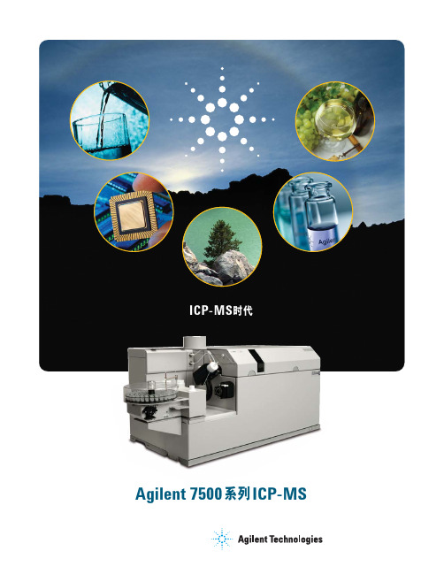
• 独特的高速双通道模式检测器,工作曲 线线性动态范围可达9个数量级
• 进样系统和接口锥采用特殊设计,耐受 环境、食品、生物、石油及地质等各种 领域的复杂高基体样品
2 /chem/icpms
ORS碰撞模式的去干扰能力
7500系列集中了所有上述创新之处,是 商品ICP-MS仪器中最具实力的系列。我 们致力于ICP-MS的创新,使我们的ICPMS用户在竞争中立于不败之地。
• STS使冷等离子体模式广泛应用于半导 体领域,其中包括高纯有机试剂的分析
5 接口与离子透镜
1 敞开的样品导入区
• 提取透镜与离轴离子透镜系统确保在整 个质量范围内均具有最高的离子传输效 率
敞开的样品导入区高精密度10个滚筒的蠕动泵位置接近于雾化器以减少样品提升与清洗时间雾化室peltierpeltier控温装置控制雾化室温度防止由于室温变化引起的信号漂移并减少氧化物的形成既可用于石英雾化室又可用于惰性雾化室可用于易挥发的有机样品的日常分析无需额外的微型的冷却装置可靠的等离子体无需维护的固态射频发生器独特的数字驱动具有最高的耦合效率2712mhz射频产生更有效的等离子体可基本完全解离样品基体达到最低的氧化物干扰与其它基体干扰通过自动调谐自动调整icp炬管位置精度高完全自动化安捷伦屏蔽炬系统屏蔽炬系统sts通过控制离子能量以增加灵敏度并利用能量歧视原理提高ors碰撞模式的去干扰能力sts使冷等离子体模式广泛应用于半导体领域其中包括高纯有机试剂的分析接口与离子透镜提取透镜与离轴离子透镜系统确保在整个质量范围内均具有最高的离子传输效离轴透镜安置于ors系统的真空阀门之前避免反应池受到污染并且无需停止真空即可进行清洗主动型质量流量控制器amfc安捷伦设计的amfc系统采用精密的电子压力传感器精确控制所有标准气流量4个氩气流量碰撞反应池系统有效去除多原子干扰
- 1、下载文档前请自行甄别文档内容的完整性,平台不提供额外的编辑、内容补充、找答案等附加服务。
- 2、"仅部分预览"的文档,不可在线预览部分如存在完整性等问题,可反馈申请退款(可完整预览的文档不适用该条件!)。
- 3、如文档侵犯您的权益,请联系客服反馈,我们会尽快为您处理(人工客服工作时间:9:00-18:30)。
频谱纯度
载波(Carrier)
相位噪声 杂波
phase noise~65dBc
0.5fo
fo
2fo
谐波
~30dBc
噪声
相位噪声 剩余调频 相位抖动
杂散
次谐波 谐波 杂波
频率
3fo
Confidentiality Label
13
December 28, 2012
信号源基础 -- 连续波(CW)信号的技术指标
衰落信号 AWGN 相位噪声
数字基 带信号 基带IQ 信号
Confidentiality Label
4
December 28, 2012
内容概要
信号源基础
-电子系统所需的测试信号 - 连续波(CW)信号 - 模拟调制与数字调制
Agilent信号源家族&竞争分析
Confidentiality Label
11
December 28, 2012
信号源基础 -- 连续波(CW)信号的技术指标
理想CW 信号
V(t) = A osin 2 fo t
Where A o = nominal amplitude f o= nominal frequency
V (t) 42 4
真实CW 信号
V (t) = [Ao + E(t)] sin [2 fot + (t)]
2
December 28, 2012
信号源基础——电子系统所需要的测试信号
RF+衰落+AWGN+……
Processing/ A/D Compression/
Error Corr
Encode I Symbols
Q
Mod I
Q
IF
RF
基带数字信号
IQ
IF
CW RF
Adaption/
Q Decode
I
D/A
RF
Microwave
3-6 GHz
Millimeter
20-30 GHz
300 GHz
•信号的频段划分
Confidentiality Label
8
December 28, 2012
信号源基础 -- 连续波(CW)信号
信号源基础
-电子系统所需的测试信号 - 连续波(CW)信号
- 模拟调制与数字调制
Confidentiality Label
6
December 28, 2012
信号源基础 -- 连续波(CW)信号
f (t) Acos(2ft 0) Acos((t))
Voltage Voltage
时间 Time
时域波形
频谱表示
频率 Frequency
幅度和相位决定一个连续波信号
信号源基础 -- 连续波(CW)信号的分类
Agilent信号源&竞争分析
连续波信号的分类
连续波信号的技术指标 连续波信号的产生
——频率合成技术
连续波信号的应用 扫描信号的特征及应用
Confidentiality Label
9
December 28, 2012
信号源基础 -- 连续波(CW)信号的技术指标
幅度指标
功率范围 幅度精度 幅度分辨率 开关速度 反向功率保护
Where E(t) = random amplitude fluctuations
(t) = random phase fluctuations E(t)
V (t)
4
2
4
(t)
Page1
信号源基础 -- 连续波(CW)信号的技术指标
幅 度
剩余调频 次谐波 sub-harmonics
信号源基础知识及产品介绍
倪勇桥 电子测试测量事业部
应用工程师 2012.10
Confidentiality Label
1
December 28, 2012
内容概要
信号源基础
-电子系统所需的测试信号 - 连续波(CW)信号 - 模拟调制与数字调制
Agilent信号源家族&竞争分析
Confidentiality Label
5
December 28, 2012
信号源基础 -- 连续波(CW)信号
信号源基础
-电子系统所需的测试信号 - 连续波(CW)信号
连续波信号的分类 连续波信号的技术指标 连续波信号的产生
——频率合成技术 连续波信号的应用 扫描信号的特征及应用
- 模拟调制与数字调制
Agilent信号源&竞争分析
10 000 Hz 1k
14
A Marker
10k1Βιβλιοθήκη 0kConfidentiality Label December 28, 2012
Frequency
f CW = aging = cal =
CW frequency = 1 GHz
aging rate = 0.1ppm/year
time since last calibrated = 1 year Accuracy = +_100 Hz
Confidentiality Label
Process/
Bits
Decompress
IF RF
Q I Demod
AGC
RF+衰落+AWGN+……
3
Confidentiality Label
3
December 28, 2012
信号源基础——电子系统所需要的测试信号
连续波 (CW)信号
调制信号
失真信号
基带信号
步进扫描 阶梯扫描 斜率扫描
模拟调制 数字调制 脉冲调制
信号源基础 -- 连续波(CW)信号的技术指标
频率指标 .
频率范围: 频率分辨率: 频率精度: 频率变化速度:
9KHz~6GHz 0.01Hz 0.1ppm/year 900us
N5182B
Voltage
Uncertainty Example Accuracy = +_ f CW* aging* cal
相位噪声指标的定义
measured as
CW output dBc/Hz
frequency 87dBc/Hz
N5182B
LogMag 5 dBc/div
-87dBc/Hz @10Hz offset -93dBc/Hz @ 100Hz offset -123dBc/Hz @1KHz offset -141dBc/Hz @10kHz offset
(-144dBm to +24dBm)
(+/- 0.6dB)
(0.01dB) (500us)
N5182B
2W
Source protected from accidental
transmission from DUT
DUT
10
Voltage
最大输出功率
信号幅度精度
最小输出功率
Frequency
Confidentiality Label December 28, 2012
