SICK 西克 条码阅读器调试手册-CLV6系列
sick 读码器CLV6xx_Commands

Applikationsbericht / Application Report Applikation:Application:CLV 6xx CommandsBearbeiter: Editor:Guenter KluemperApplikation Div05Phone:Fax:E-Mail:+49 (0) 76 41-4 69-1706+49 (0) 76 41-4 69-1290************************26. May. 2011Verteiler:Copy to:Content:1.General structure of SOPAS-Telegramm (2)2.Error handling (3)3.Control of Outputs direct at CLV 6xx (cable version) using commands (4)4.Control of External Outputs at CLV 6xx with CMC 600 (5)5.Reading of Inputs and Outputs of CLV 6xx (6)6.Register Inputs and Outputs of CLV 6xx (7)7.Change Codeconfig, Sample 1 (9)8.Change Codeconfig, Sample 2 (11)9.Set Matchcode at direct connected Scanner using Sopas Command (13)10.Set Matchcode in CAN-Network using Sopas Hub-Commands (13)11.SW-Trigger via CAN-Bus using Sopas Hub-Commands (14)12.SW-Trigger using Sopas ET (16)12.1 Trigger as 21/22 without echo (18)12.2 Trigger as 21/22 with echo (18)12.3 Trigger via Sopas Commands (19)13.Readout of Operating Data via Commands (20)14.List of usefull commands: (21)15.Short form Non-Sopas commands for Matchcodes (CLV 6xx V3.20 or higher) (22)16.Handling of variables from type “Real” and “LReal” (25)17.Handling of Application counters (27)1. General structure of SOPAS-TelegrammEach SOPAS Telegramm includes• the TYP of the request (e.g. sMN), • the Name of the Methode/Variable and • the Parametern .The type indicates wheather the request is a Variable, a Method or an Event. The first character is always the lower case …s“.SOPAS-Commands are always framed with STX/ETX.SOPAS-Telegram (for sending) [STX]sWN FTScanFrq 10[ETX]SOPAS-Telegram (receiving)[STX]sANSetAccessMode 1[ETX]2. Error handlingIf an error occurs the Sopas command is answered with: [STX]sFA <x>[ETX] as an error response Error list: <x> can have following values:1: Access denied2: Unknown Index3: Unknown Index4: Wrong Condition5: Invalid Data6: Unknown Error7: Too Many Parameter8: Parameter Missing9: Wrong ParameterA: No Write AccessB: Unknown CommandC: Unknown CommandD: Server BusyE: Textstring Too LongF: Unknown Event10: Too many Parameter11: Invalid Character12. No Message13: No Answer14: Internal Error15: HubAddress: wrong16: HubAddress: error17: HubAddress: error3. Control of Outputs direct at CLV 6xx (cable version) using commandsUse only cable version and not Ethernet-Version !Parametration: Outputs must be set to CommandCommand:[STX]sMNmDOSetOutput 2 1[ETX][STX] Start char, Hex 02sMN Sopas Method by NamemDOSetOutput Command for digital output of CLV 6xxspace for separation2 Output No 2, (or Output No 1)space for separation1 1 = Output is set, 0 = Output is reset[ETX] Stop char, Hex 03Answer of command:[STX]sAN mDOSetOutput 1[ETX] (positive)[STX]sAN mDOSetOutput 0[ETX] (negative, e.g when an Ethernet version is used, orwhen output is not set to be controlled via command) Command:[STX]sMNmDOSetOutput 1 1[ETX] Sets Output No 1[STX]sMNmDOSetOutput 1 0[ETX] Resets Output No 1[STX]sMNmDOSetOutput 2 1[ETX] Sets Output No 2[STX]sMNmDOSetOutput 2 0[ETX] Resets Output No 2Test with See-It:4. Control of External Outputs at CLV 6xx with CMC 600Works with both Cable and Ethernet-Version, but a CMC 600 must be installedParametration: External Outputs must be set to CommandCommand:[STX]sMNmEOSetOutput 2 1[ETX][STX] Start char, Hex 02sMN Sopas Method by NamemEOSetOutput Command for external digital output of CLV 6xxspace for separation2 External Output No 2, (or External Output No 1)space for separation1 1 = Output is set, 0 = Output is reset[ETX] Stop char, Hex 03[STX]sMNmEOSetOutput 1 1[ETX] Sets External Output No 1[STX]sMNmEOSetOutput 1 0[ETX] Resets External Output No 1[STX]sMNmEOSetOutput 2 1[ETX] Sets External Output No 2[STX]sMNmEOSetOutput 2 0[ETX] Resets External Output No 2Test with See-It:5. Reading of Inputs and Outputs of CLV 6xxCommand: [STX] sRN eIN1[ETX] reads first digital Input (Sensor1) [STX] Start char, Hex 02sRN Sopas Read by Namespace for separationeIN1 Command for first digital input (sensor 1) of CLV 6xx[ETX] Stop char, Hex 03Answer: [STX]sRA eIN1 8DB22 B114 0[ETX] answer of clv 6xx[STX] Start char, Hex 02sRA Sopas Read Answerspace for separationeIN1 Command for first digital input of CLV 6xxspace for separation8DB22 additional value for inc / timestamp, can vary in content and lengthspace for separationB114 additional value for inc / timestamp, can vary in content and lengthspace for separation0 → State of Sensor1: 0 or 1[ETX] Stop char, Hex 03List of all readable in and outputs:[STX]sRN eIN1[ETX] → Sensor 1[STX]sRN eIN2[ETX] → Sensor 2 (only at standard cable version of CLV 6xx) [STX]sRN eResult1[ETX] → Result 1 (only at standard cable version of CLV 6xx) [STX]sRN eResult2[ETX] → Result 2 (only at standard cable version of CLV 6xx) [STX]sRN eExtIn1[ETX] → External Input 1 (only at CMC / CDF 600)[STX]sRN eExtIn2[ETX] → External Input 2 (only at CMC / CDF 600)[STX]sRN eExtOut1[ETX] → External Output 1 (only at CMC / CDF 600)[STX]sRN eExtOut2[ETX] → External Output 2 (only at CMC / CDF 600)[STX]sRN eReadingGate[ETX]Test with See-It: CLV 6xx cable version with CMC 600:6. Register Inputs and Outputs of CLV 6xxInstead of polling the inputs as described you can get register an input or output. Than you get a message when the state of these in- or outputs has changed.Command: [STX] sEN eIN1 1[ETX] register first digital Input (sensor1) [STX] Start char, Hex 02sEN Sopas register Event by Namespace for separationeIN1 Command for first digital input (sensor 1) of CLV 6xxspace for separation1 set register to active (0 = sets register back to inactive)[ETX] Stop char, Hex 03Answer: [STX]sEA eIN1 1[ETX] answer of clv 6xx[STX] Start char, Hex 02sEA Sopas Event Anwerspace for separationeIN1 Command for first digital input (sensor 1) of CLV 6xxspace for separation1 register status[ETX] Stop char, Hex 03When registered this string is send when the in/output has changed:[STX]sSN eIN1 8DB22 B114 0[ETX] answer of clv 6xx[STX] Start char, Hex 02sSN Sopas State by Namespace for separationeIN1 Name of the in / outputspace for separation8DB22 additional value for inc / timestamp, can vary in content and lengthspace for separationB114 additional value for inc / timestamp, can vary in content and lengthspace for separation0 → State of in / output: 0 or 1[ETX] Stop char, Hex 03List of all in and outputs which can be registered:[STX]sRN eIN1[ETX] → Sensor 1[STX]sRN eIN2[ETX] → Sensor 2 (only at standard cable version of CLV 6xx) [STX]sRN eResult1[ETX] → Result 1 (only at standard cable version of CLV 6xx) [STX]sRN eResult2[ETX] → Result 2 (only at standard cable version of CLV 6xx) [STX]sRN eExtIn1[ETX] → External Input 1 (only at CMC / CDF 600)[STX]sRN eExtIn2[ETX] → External Input 2 (only at CMC / CDF 600)[STX]sRN eExtOut1[ETX] → External Output 1 (only at CMC / CDF 600)[STX]sRN eExtOut2[ETX] → External Output 2 (only at CMC / CDF 600)[STX]sRN eReadingGate[ETX]Test with See-It: CLV 6xx cable version with CMC 600: Registered and additional an change of the inputs:Only register:7. Change Codeconfig, Sample 1Task:- Select 2/5-Interleaved with Multiread of 5 and allow only the following length:14 char length with Check Digit = Modulo 10,10 char length with Check Digit = W49M10,8 char length without Check Digit Test- Switch off EAN / UPCA,Command: (comments)Answer:[STX]sRI0[ETX] [STX]sRA 0 6 CLV62x 10 V2.00-07.12.2007[ETX] (to see what scanner is connected)[STX]sMI 0 03 F4724744[ETX] [STX]sAI 0 1[ETX](Login as client)[STX]sWN DCC25ILAct 1[ETX] [STX]sWA DCC25ILAct[ETX](activate 2/5-Interleaved)[STX]sWN DCC25ILLenMode 2[ETX] [STX]sWA DCC25ILLenMode[ETX](set to fix length)Values for Length mode: 0, 1, 2:(set length of 14, 10 an 8, command uses hex-values)[STX]sWN DCC25ILMrL1 5[ETX] [STX]sWA DCC25ILMrL1[ETX] (set multiread to 5)[STX]sWN DCC25ILCdTstL1 1[ETX] [STX]sWA DCC25ILCdTstL1[ETX] (set checkdigit for first length to Modulo10)Values for Check digit mode: 0, 1, 2, 3, 5:[STX]sWN DCC25ILCdTstL2 3[ETX] [STX]sWA DCC25ILCdTstL2[ETX] (set checkdigit for secondt length to W49M10)[STX]sWN DCC25ILCdTstL3 0[ETX] [STX]sWA DCC25ILCdTstL3[ETX] (set checkdigit for thirth length to none)[STX]sWN DCUPCEANAct 0 [ETX] [STX]sWA DCUPCEANAct[ETX] (deactivate EAN / UPC)[STX]sMN mEEwriteall[ETX] [STX]sMN mEEwriteall 1[ETX] (optional: save all parameter permanent”)[STX]sMI 2[ETX] [STX]sAI 2 1[ETX](Logout)Result using See-It:8. Change Codeconfig, Sample 2Task:- Switch off 2/5-Interleaved,- Select EAN 13 and UPCA with Multiread = 5.Command: (comments)Answer:[STX]sRI0[ETX] [STX]sRA 0 6 CLV62x 10 V2.00-07.12.2007[ETX] (to see what scanner is connected)[STX]sMI 0 03 F4724744[ETX] [STX]sAI 0 1[ETX](Login as client)[STX]sWN DCUPCEANAct 1 [ETX] [STX]sWA DCUPCEANAct[ETX](activate UPC/EAN)[STX]sWN DCUPCEANMr 5[ETX] [STX]sWA DCUPCEANMr[ETX](set Multiread to 5)[STX]sWN DCUPCAAct 1[ETX] [STX]sWA DCUPCAAct[ETX](activate UPC A)[STX]sWN DCUPCEAct 0[ETX] [STX]sWA DCUPCEAct[ETX](deactivate UPC E)[STX]sWN DCEAN8Act 0[ETX] [STX]sWA DCEAN8Act[ETX](deactivate EAN 8)[STX]sWN DCEAN13Act 1[ETX] [STX]sWA DCEAN13Act[ETX] (activate EAN 13)[STX]sWN DCC25ILAct 0[ETX] [STX]sWA DCC25ILAct[ETX] (deactivate 2/5-Interleaved)[STX]sMN mEEwriteall[ETX] [STX]sMN mEEwriteall 1[ETX] (optional: save all parameter permanent”)[STX]sMI 2[ETX] [STX]sAI 2 1[ETX] (Logout)Result using See-It:9. Set Matchcode at direct connected Scanner using Sopas Command Comunication test (optional):Host: [STX]sRI0[ETX]CLV: [STX]sRA 0 6 CLV62x 11 V2.40a-aa.04.2008[ETX]Login as client:Host: [STX]sMI 0 03 F4724744[ETX]CLV: [STX]sAI 0 1[ETX]Set Matchcode Match123 to "55443": (one space between each block)Host: [STX]sMN mEVSetMatchCode 0040 name="Match123" content="55443*" length="11" codeType="dontCare"[ETX]CLV: [STX]sAN mEVSetMatchCode 1[ETX]optional: save all parameter permanent:Host: [STX]sMN mEEwriteall[ETX]CLV: [STX]sMN mEEwriteall 1[ETX]Logout:Host: [STX]sMI 2[ETX]CLV: [STX]sAI 2 1[ETX]Result in Sopas: Evaluation Condition:10. Set Matchcode in CAN-Network using Sopas Hub-CommandsCAN-Network with two scanners:Scanner 07 is Multiplexer The serial Host-Port of this scanner is connected to the Host Scanner 04 is ServerIn a CAN-Network all scanners can be adressed using a Sopas Hub-Aderess in front of each command. Also the answer has the same Hub-Adress in front of it.Sopas Hub Command:{ 00 01 04}{ Identifier for Hub-Aadress, hex 7Bblank for separation00 fix 00blank for separation01 fix 01, because we just want to go to one additional deviceblank for separation04ID of the adressed scanner, here scanner 04} End of Hub-Aadress, hex 7DThese commands must be send from the Host to the scanner to set the matchcode: Comunication test (optional):Host: [STX]s{ 00 01 04}RI0[ETX]CLV: [STX]s{ 00 01 04}RA 0 6 CLV62x 10 V2.40-10.04.2008[ETX]Login as client:Host: [STX]s{ 00 01 04}MI 0 03 F4724744[ETX]CLV: [STX]s{ 00 01 04}AI 0 1[ETX]Set Matchcode Match123 to "04443": (one space between each block)Host: [STX]s{ 00 01 04}MN mEVSetMatchCode 0040 name="Match123" content="04443*" length="11" codeType="dontCare"[ETX]CLV: [STX]s{ 00 01 04}AN mEVSetMatchCode 1[ETX]Logout:Host: [STX]s{ 00 01 04}MI 2[ETX]CLV: [STX]s{ 00 01 04}AI 2 1[ETX]Result in Sopas: Evaluation Condition:Result using See-It:11. SW-Trigger via CAN-Bus using Sopas Hub-CommandsExample with 3 Scanner CLV 6xx at ID 01, 02 and 03 running in CAN-Bus as Multiplexer / Server. All scanners are programmed to trigger via Command. All scanner should be triggered separately.Multiplexer Scanner (ID 01) itself: (here no Hub adress is used) Trigger ON:Host: [STX]sMN mTCgateon[ETX]CLV: [STX]sAN mTCgateon 1[ETX]Trigger Off:Host: [STX]sMN mTCgateoff[ETX]CLV: [STX]sAN mTCgateoff 1[ETX]CLV: [STX]01} 1234567890[ETX] (read result) Scanner ID 02Trigger ON:Host: [STX]s{ 00 01 02}MN mTCgateon[ETX]CLV: [STX]s{ 00 01 02}AN mTCgateon 1[ETX]Trigger Off:Host: [STX]s{ 00 01 02}MN mTCgateoff[ETX]CLV: [STX]s{ 00 01 02}AN mTCgateoff 1[ETX]CLV: [STX]02} 1234567890[ETX] (read result) Scanner ID 03Trigger ON:Host: [STX]s{ 00 01 03}MN mTCgateon[ETX]CLV: [STX]s{ 00 01 03}AN mTCgateon 1[ETX]Trigger Off:Host: [STX]s{ 00 01 03}MN mTCgateoff[ETX]CLV: [STX]s{ 00 01 03}AN mTCgateoff 1[ETX]CLV: [STX]02} 1234567890[ETX] (read result) Scanner ID 10 dec (here ID must be written in hex).Trigger ON:Host: [STX]s{ 00 01 0A}MN mTCgateon[ETX]CLV: [STX]s{ 00 01 0A}AN mTCgateon 1[ETX]Trigger Off:Host: [STX]s{ 00 01 0A}MN mTCgateoff[ETX]CLV: [STX]s{ 00 01 0A}AN mTCgateoff 1[ETX]CLV: [STX]10} 1234567890[ETX] (read result) Commandlist:[STX]sMN mTCgateon[ETX][STX]sMN mTCgateoff[ETX][STX]s{ 00 01 02}MN mTCgateon[ETX][STX]s{ 00 01 02}MN mTCgateoff[ETX][STX]s{ 00 01 03}MN mTCgateon[ETX][STX]s{ 00 01 03}MN mTCgateoff[ETX]Using See-It:12. SW-Trigger using Sopas ET Softwaretrigger at CLV 6xxParametrize the scanner to be triggered via command:Please use the terminal emulator and connect it to the scanner .Chose than this option and press “connect”.Take also care that the terminal setting at framing are as below set to 02 and 03:12.1 Trigger as 21/22 without echoHere the option "trigger echo on" is NOT activated. The command do not have than an echo. Than you can type in the commands like "21" for trigger start and "22" for trigger stop. The commands are send by pressing Enter or use the green send button at the end.The data are automatically framed with STX / ETX.12.2 Trigger as 21/22 with echoHere the option "trigger echo on" is activated. The command do have than an echo.12.3 Trigger via Sopas CommandsYou can also use the original Sopas commands to trigger the scanner. These commands do all times have an echo.sMN mTCgateon ==> Trigger startsMN mTCgateoff ==> Trigger stop13. Readout of Operating Data via CommandsIn Sopas ET at Service / Operating Data the following data are displayed:The data can be also queried using the following commands:Host: [STX]sRN DImanf[ETX] (Manufacturer) CLV: [STX]sRA DImanf 7 SICK AG[ETX] (7 char, content "SICK AG")Host: [STX]sRN DItype[ETX] (Device Type) CLV: [STX]sRA DItype B CLV620-0000[ETX] (Length = Bhex = 11dec)Host: [STX]sRN DIornr[ETX] (Order Number) CLV: [STX]sRA DIornr 1040288[ETX]Host: [STX]sRN FirmwareVersion[ETX] (Software Version) CLV: [STX]sRA FirmwareVersion 5 V3.05[ETX]Host: [STX]sRN SerialNumber[ETX] (Serial Number) CLV: [STX]sRA SerialNumber 8 08270385[ETX]Host: [STX]sRN ODpwrc[ETX] (Power-On Counter) CLV: [STX]sRA ODpwrc B6[ETX] (B6hex = 182dec) Host: [STX]sRN ODoprh[ETX] (Operating Hours) CLV: [STX]sRA ODoprh 8C36[ETX] (8C36hex = 35894dec x 0,1h)Host: [STX]sRN ODopdaily[ETX] (Operating Hours since Power on) CLV: [STX]sRA ODopdaily 3EDDDDE5[ETX] (IEEE-754 single precision, 32 bit, float)Host: [STX]sRN DIuser[ETX] (Last Username) CLV: [STX]sRA DIuser 7 kluemgu[ETX]Host: [STX]sRN DIpara[ETX] (Last Parametrization Date) CLV: [STX]sRA DIpara A 01.03.2010[ETX]Host: [STX]sRN DIparatm[ETX] (Last Parametrization Time) CLV: [STX]sRA DIparatm 5 11:56[ETX]14. List of usefull commands:Comunication test: (shows version of Sopas JAR/SDD file)Host: [STX]sRI0[ETX]CLV: [STX]sRA 0 6 CLV63x 10 V3.00-14.05.2009[ETX]Read Location Name: (This name is displayed when searching with Sopas for a device) Host: [STX]sRN LocationName[ETX]CLV: [STX]sRA LocationName 6 CAN_12[ETX] (here 6 char, content "CAN_12") Read Firmwareversion: (shows the real firmware version of the device)Host: [STX]sRN FirmwareVersion[ETX]CLV: [STX]sRA FirmwareVersion 5 V3.05[ETX]Login as client: (using Index)Host: [STX]sMI 0 03 F4724744[ETX]CLV: [STX]sAI 0 1[ETX]Login as client: (using name command)Host: [STX]sMN SetAccessMode 03 F4724744[ETX]CLV: [STX]sAN SetAccessMode 1[ETX]Set to factory default: (All parameters are set to default !)Host: [STX]sMN mSCloadfacdef[ETX]CLV: [STX]sAN mSCloadfacdef[ETX]save all parameters permanent:Host: [STX]sMN mEEwriteall[ETX]CLV: [STX]sMN mEEwriteall 1[ETX]Logout: (using Index)Host: [STX]sMI 2[ETX]CLV: [STX]sAI 2 1[ETX]Logout: (using name command)Host: [STX]sMN Run[ETX]CLV: [STX]sAN Run 1[ETX]In general the name commands should be used, but index commands with the index 0 to 7 are also identical at all Software-Versions and may be used as shorter alternative.15. Short form Non-Sopas commands for Matchcodes (CLV 6xx V3.20 or higher) This command is accepted at all interfaces (Ser-Aux, Ser-Host, Eth-Aux, Eth-Host) of CLV 6xx. It did not need a login/logout or save. This single command handles it all in one.Format of the non sopas command for defining Matchodes:Example: <STX> 2 MC 1 0 b barcode * <ETX> (no blanks in between !) Explanation of the positions within the command:<STX> Header character (always <STX> !)2 Command Identifier character (always 2)2: commands which can be handled without login/logoutMC This commands defines a match condition (Always 'MC')1 Defines if the name of the match condition:Valid numbers: 1 .. 91: Condition name = Match12: Condition name = Match2...9: Condition name = Match9The condition name "Matchx" must already be defined in the CLV0 Defines if the condition must be stored permanently and if an Echo is send:0: don't store permanently, no Echo1: store permanently, no Echo2: don't store permanently, with Echo (can be used at V5.10 or higher)3: store permanently, with Echo (can be used at V5.10 or higher) b: Barcode Type Identification character (CodeID)a, CBAR, CODABAR,b, C39, CODE39,c, UPC, UPC,d, EAN, EAN,e, 25IL, INTERLEAVED25,f, 25IN, C25IND, 25STRAIGHTIATAg, MSI, MSI CODE,h, CODE11i, C93, CODE93,j, C128, CODE128,l, PLESSYm, MATRIX2OF5,n, E128, EAN 128,o, PHRM, PHARMA,p, GS1 DataBar Expanded,r, PDF417,s, QRC, QR CODE,t, TELEPEN,u, GS1 DataBar Limited,w, MAXICODE,y, GS1_DATABAR,z, AZTEC,A, POST_AUSTRALIA,B, RM4SCC,J, JAPO, JAPANESE POSTAL,<, CODE32 (6 digit C39 decodes as C32)*: Barcode type is 'don't care' and won't be checkedbarcode Content of the machcode.The length of the matchcode is according to number of characters here.* If the last character of the barcode is '*' then the length of the matchcode will not be checked. The content of the match condition then is 'barcode*'(so with * at the end). Than all code will match which begin with the content“barcode”.<ETX> Terminating character (always <ETX> !)The scanner will do send an echo at this command, when it is parametrized.Additional a small GoodRead beep is done when the code was accepted, and a NoRead beep is done when the code is not accepted (e.g. when Match9 is used and Match9 is not parametrized before in the the CLV).The option “Code validity” is fixed set to “Match only valid code”, which should fit for most applications.Example #1:use Match1 set to content "abcd", save temporarly, Code ID= b, so Code 39 Data using See-It: Result in Sopas:Example #2:use Match1 set to content "12345678", save temporarly, Code ID= *, so don’t care Data using See-It: Result in Sopas:16. Handling of variables from type “Real”and “LReal”In Sopas / CLV 6xx some variables are defenid as type “R eal”and “LReal”. This is an Floating-Point format which is defined in IEEE-754.The format contain a sign, the exponent and a mantisse.For more details see IEEE 754 Specification.Real IEEE-754 single precision (32 bit) (float)LReal IEEE-754 double precision (64 bit) (double)Examples:- Min reading angle of CLV 6xx: RCMinCPDec= 15.0 == 41700000 as hex-value- Max reading angle of CLV 6xx: RCMaxCP:Dec= 85.0 == 42AA0000 as hex-valueMore informations about this format:/wiki/IEEE_754Converter for this format:/FloatApplet/IEEE754.htmlExample: Type in 15 + Enter and you get the hex value: 41700000 /IEEE-754/Decimal.htmlBeispiele:Dec: Hex:0 0000000015 4170000049.8 4247333350 4248000065 4282000085 42AA0000100 42C8000017. Handling of Application countersThe Application counters can be queried with the below command:sRN APCCntxx (xx = 01, 02, 03, … 10)Query Application Counter 01: The value is in Hex.Host: [STX]sRN APCCnt01[ETX]CLV: [STX]sRA APCCnt01 20[ETX] (20 hex = 32 dec.) Query Application Counter 02: The value is in Hex.Host: [STX]sRN APCCnt02[ETX]CLV: [STX]sRA APCCnt02 1B[ETX] (1B hex = 27 dec.) …Query Application Counter 10: The value is in Hex.Host: [STX]sRN APCCnt10[ETX]CLV: [STX]sRA APCCnt10 0[ETX]Example:A Reset of all ten Application counters can be forced with this command:sMN mAPCReset (No login needed)Reset all Application Counters:Host: [STX]sMN mAPCReset[ETX]CLV: [STX]sAN mAPCReset[ETX]Example:。
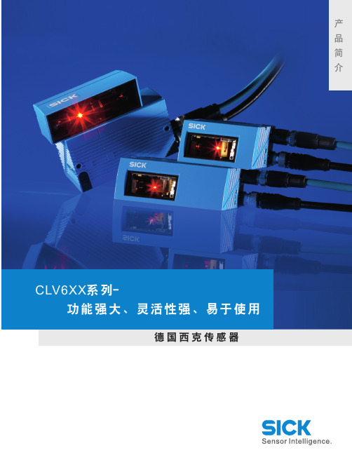
SICK条码扫描器CLV6
过使用外部参数克隆功能实现的无需
使用电脑进行配置,这样可以保证快
速的平均修复时间 (MTTR)*)。
聚焦 固定聚焦型号用于固定焦距的应用, 动态聚焦型号用于有多种读取距离的 应用,还可以根据实时集成距离检测 仪实现自动对焦点转换(无需再配备 光电传感器)。
优化全部生产过程
现今,企业要发展,必须 注重过程而不是功能;必 须排除不灵活的工作过程, 全面优化价值的生产过程。 因此,必须要有一个整体 的,而不是单纯地解决某 一问题的自动化解决方案。
作为全球自动化、安全技 术、环境监测系统和自动 识别系统等传感器领域的 佼佼者,SICK公司致力于 发展工业过程的现代化和 合理化。
阅读距离 • 利用外部参数克隆功能实现快速、简便的更换条
码扫描器
汽车行业
• 阅读距离远 • 具有自动聚焦和动态聚焦型号 • 灵活的现场总线连接 • 快速接头方式 • 无硅 • 利用外部参数克隆功能实现快速、简便的更换条码扫
描器
电子行业
• 紧凑型产品,适用于宽度极小的模块 • 对部分遮盖、污损或对比度低的条码都能提供优异的
• 多样的聚焦模式(固定聚焦、动态聚焦和自动聚焦)几 乎覆盖了所有的读取距离
易于使用
• 简单直观的用户界面 SOPAS-ET Single Device 或 SOPASET(请参见第 32 页)
• 配备连接助手,连接条码扫描器更快捷。无需额外的现 场总线。
• 通过集成按钮、LED 条形图和智能化自动设置功能即可 实现简便设置,无需电脑主机。
外部镜罩 邻输送带之间时,外部镜罩可以缩短阅读距离。
前置读取窗口
侧面读取窗口
侧面读取窗口, 带摆镜
线式扫描器 光栅扫描器 线式扫描器,带摆镜
SICK条码扫描器使用指南

新打储打自出 下上设设监 辅网 建开存印动厂 载载备备控 助络 文文文参连参 参参信功画 工检 档档档数接数 数数息能面 具测
ୋ 6 䔍 38 䔍
10. 你可随时按 F1 或选择“Help”,获得在线帮助。
广州市施克传感器有限公司
11. 以下用示图加文字的方式介绍各分项的使用方法。
ୋ 4 䔍 38 䔍
广州市施克传感器有限公司
(快捷键 F10)打开调试窗口,将条码静止置于阅读区域内,如图所示点击 Auto Setup(自 动设置),确保激光正对条码,这时条码阅读器会自动对该条码及阅读距离进行扫描频 率及其他参数的设定,设定完成后会自动保存在条码阅读器中。以上设置完成后再根据 物体(条码)运动速度来进行调整。现提供以下方法,仅供参考,实际设定时需要通过 测试来最好确定扫描频率: 当物体运动速度小于 1 米/秒时,一般不需要再进行参数调整; 当物体运动速度大于 1 米/秒时,可以根据情况将频率增加 100Hz-400Hz,直至达到条码 阅读器最大扫描频率。
ࡾɺ CVL Setup 软件使用说明
1. 请在 Windows 操作系统下安装(版本 3.2 以后须安装在 32 位操作系统下) 2. 运行光盘中 CLV setup.exe 程序进行安装 3. 语言选择英语 English , 单位选择 mm . 4. 安装完成后,运行 “ Clv Setup ” 进入参数设置画面。 5. 在画面右上方的 “ Device ” 栏中选择所用的扫描仪型号。 6. 软件会自动通过串口搜索该设备,若连接成功,右下角或右上角(视软件版本而定)
Distance Configuration / Assignment Table
中文 条码中最细 Bar 条宽度 扫描频率 条码前后的空白区域
条码阅读器调试手册CLV4XX

中文 传感器输入,高电平触 发,激光打开 传感器输入,低电平触 发,激光打开 串行口软件触发,激光 打开
说明 要求传感器为 PNP 型输 出,输出为高电平是触发。 要求传感器为 PNP 型输 出,输出为低电平是触发。 用指令触发
第 13 页 共 40 页
Free Running with Timeout OPC-Trigger
要采用屏蔽双绞线。
第 7 页 共 40 页
杭州汇源自动化-----陈鑫
扫描器 CAN 网络电气连接图
3、单台条码阅读器参数设置及调试
1、SICK 扫描器的调试和参数设置一般通过扫描器的 Terminal 端口进行。也就 是通过接线盒 CDB420 中的 AUX Interfac(e 9 针插头)将扫描器与计算机相连接。 连接电缆的选用 2-3 交叉串口通信电缆,电缆的连线如下图所示,
自学习方式
第 16 页 共 40 页
说明 可指定条码类型及内容; 若选 Not relevant,是指 不管条码类型。 若不选,匹配结果不影响 串口输出 有动态匹配、不含医药码 固定匹配、含医药码固定 匹配三种
Counter-Reset on Teach-In
杭州汇源自动化-----陈鑫
在教导式输入新匹配条 码时是否复位计数器
第 14 页 共 40 页
杭州汇源自动化-----陈鑫
在 Result Output Parameters 下:(一般要修改,根据实际需要选择)
英文 Output 1 Output 2
Invert Output Beeper Pulse Width中文说明输出源自1可代表准备就绪、读取成功、
输出 2
第 2 页 共 40 页
杭州汇源自动化-----陈鑫
SICK条码扫描器使用

说明 可代表准备就绪、读取成功、 读不到、条码个数大于/小于 设定值、匹配、不匹配、参 考值与限制值的比较等条码 器状态信息,由下拉菜单选 择决定。
有关、小声、大声三种
ୋ 13 䔍 38 䔍
广州市施克传感器有限公司
(5)Match Code Parameters 匹配条码参数:
会出现绿色 “Connected” 若出现红色 “ No Connection”即表示连接失败.
ୋ 5 䔍 38 䔍
7. 若连接失败,可选择握手图框,自动测试通信协定
广州市施克传感器有限公司
8. 若还不能连接,请检查通信电缆是否连接正确,例如: Com Port 是否正确? RS232 中,针角是否按如下连接? RxD → TxD , TxD → RxD GND → GND .
ୋ 10 䔍 38 䔍
广州市施克传感器有限公司
(3)Reading Trigger Parameters 阅读触发信号源参数:
英文 Sensor Input (Active High) Sensor Input (Active Low)
Serial Interface Free Running with Timeout OPC-Trigger Reflector Polling Continuous Read
广州市施克传感器有限公司
CLV 条码阅读器 使用指南
ୋ 1 䔍 38 䔍
广州市施克传感器有限公司
目
录
1. 条码阅读器的安装步骤----------------------------- (1) 2. 条码阅读器扫描频率设定方法----------------------- (4) 3. CVL Setup 软件使用说明--------------------------- (5) 4. 附录 1:CLV44X 动态聚焦功能使用方法--------------- (23) 5. 附录 2:SICK CAN-SCANNER-NETWORK 介绍------------- (29)
SICK中国公司IDM1xx_2xx配对设置及Profinet通讯手册说明书

IDM1xx_2xx配对设置及Profinet通讯手册类型:调试指导版本:V1.0 日期:2017-5-26目录1.手持读码器类型 (3)2.硬件连接 (3)3.手持枪的供电及状态说明 (4)3.1.手持枪供电 (4)3.2.手持枪指示灯状态及含义 (4)4.手持枪设置连接模式 (6)4.1.无线蓝牙手持枪支持的PICO、PAIR模式 (6)4.2.PAIR模式 (6)4.3.DPM功能激活 (7)5.手持抢参数设置 (7)6.CDF600-2200设置 (9)6.1.硬件设置 (9)6.2.软件设置 (10)7.PLC通讯设置 (10)7.1.下载GSDML文件 (10)7.2.添加GSD文件 (12)7.3.设备组态并设置CDF600-220x (13)7.4.通讯字符握手说明 (14)7.5.通讯字符握手设置 (15)1. 手持读码器类型本操作手册针对以下产品中除IDM142 WIFI、IDM162 WIFI型外其他所有接口为RS232型手持式条码阅读器。
2. 硬件连接我公司Profinet网关有两种型号,本文中以常用型号CDF600-2200为例,设备连接方式如下图所示:3. 手持枪的供电及状态说明3.1. 手持枪供电3.2. 手持枪指示灯状态及含义4. 手持枪设置连接模式4.1. 无线蓝牙手持枪支持的PAIR 、PICO模式PAIR模式表示手持枪主体和底座为一对一连接,为最通用模式;PICO模式为手持枪主体和底座为一对多连接。
一个蓝牙底座最多支持7个手持枪主体。
4.2. PAIR模式4.3. DPM功能激活(可选)5. 手持抢参数设置按照以下表格从上往下扫描:顺序内容条形码1 恢复出厂默认设置2 设置为RS232通讯模式3 进入设置模式设置波特率为96004设置STX/ETX为前后缀56 设置数据位格式为:n,8,1.7 删除CR结束符8 结束设置如果有条件,建议先把手持枪底座与电脑通过RS232进行通讯连接,打开串口监控工具,查看数据格式是否已经设置成功。
CLV65x条码辨读器 说明书

自動辨識系統條碼辨讀器 - CLV65x系列C LISTED 4R97可旋轉式接頭僅限於乙太網路型可旋轉的接頭設計讓CLV6系列產品可以安裝於許多以往不可能安裝的地方,因此,如此完善的網路架構可提供快速的插拔與靈活的安裝方式。
讀取範圍示意圖自動對焦讀取範圍讀取距離(mm)自動對焦讀取範圍讀取距離(mm)自動對焦,低解析度讀取範圍掃瞄頻率(Hz)對焦位置(mm)自動對焦,低解析度掃瞄頻率(Hz)讀取範圍對焦位置(mm)正面投光鏡面擺動式(側面)7006506005505004504003503002502005004003002001000-200-100-300-400-500(mm)(mm)(mm)(mm)雷射讀取角度 25°雷射讀取角度 25°1 最大讀取距離 (傾斜角度 0°)2 最大讀取距離 (傾斜角度 45°)3 最小讀取距離4 景深,傾斜角度 0°5 景深,傾斜角度45°產品資訊自動對焦,標準型自動對焦,乙太網路型CLV650-0000CLV650-6000CLV651-0000CLV651-6000CLV650-0120CLV650-6120CLV651-0120CLV651-6120單線式,正面投光多線式,正面投光單線式,側面投光,低解析度多線式,側面投光,低解析度單線式,正面投光多線式,正面投光單線式,側面投光,低解析度多線式,側面投光,低解析度1 041 2901 042 1241 046 5571 046 5591 042 1211 042 1251 046 5581 046 560產品型號產品說明訂貨代號自動辨識系統 條碼辨讀器 - CLV65x系列鏡面擺動型(側面)-乙太網路型單位:mm正面投光-乙太網路型。
SICK 西克 条码阅读器调试手册-CLV6系列

OFF ON
输出信号为+24V,
最大电流100mA
13 16
14
GND Result1 T+
S3
ON
CDB420-001
OFF
CDB420-001接线端子
15 24 25 26 17 27 28
29
R+ T- R- GND SGND SGND Sensor1 +24V
蜂鸣器及报警灯 继电器
R+ T+ R- T- GND RS422-RS232转换器
3、单台条码阅读器参数设置及调试
广州市施克传感器有限公司
1、SICK 扫描器的调试和参数设置一般通过扫描器的 Terminal 端口进行。也就 是通过接线盒 CDB420 中的 AUX Interfac(e 9 针插头)将扫描器与计算机相连接。 连接电缆的选用 2-3 交叉串口通信电缆,电缆的连线如下图所示,
Multiread:重复次数,默认为 3,1-99 可选。速度越快,设定重复次 数越少。
Free:指条码的长度是随意的,只要是这类条码都识别。 Fixed:指条码的长度是固定的,跟此长度不同的不识别。
第 17 页 共 36 页
广州市施克传感器有限公司
在 Serial 下: (一般要修改,根据实际需要选择)
在 Output Control 下:(一般要修改,根据实际需要选择)
第 14 页 共 36 页
英文 End of Trigger As soon as possible
End of Label New Label
Single
Multiple
Good Read Condition Match1 Condition TeachIn1 Condition TeachIn2
(完整版)SICK条码扫描器使用指南
CLV 条码阅读器使用指南目录1.条码阅读器的安装步骤----------------------------- (1)2.条码阅读器扫描频率设定方法----------------------- (4)3.CVL Setup软件使用说明--------------------------- (5)4.附录1:CLV44X动态聚焦功能使用方法--------------- (23)5.附录2:SICK CAN-SCANNER-NETWORK介绍------------- (29)一、条码阅读器的安装步骤1.条码阅读器的对准条码阅读器安装的第一步首先需要将条码阅读器的激光与被阅读的条码对准,这样才能保证阅读效果。
上图所示为三种不同类型的扫描器的对准方法。
(1)单线式条码阅读器,首先使条码阅读器的光线垂直于条码方向,同时条码阅读器将激光的中心位置对准条码。
(2)多线式条码阅读器,首先使条码阅读器的光线平行于条码方向,同时调整条码阅读器使激光对准条码的中心位置。
(3)对于摆动镜式阅读器,首先使条码阅读器的光线平行于条码方向,同时调整条码阅读器以保证所有的条码都位于激光的阅读区域内。
2.安装距离和角度扫描器的安装距离是指从扫描器的窗口到条码表面的距离。
下图所示为阅读距离的测量方法,每种型号的条码阅读器的阅读距离都不同,因此安装过程中阅读距离的确定需要查阅相关型号的技术参数。
为了避免条码表面对激光直接的反射,条码阅读器一般不采取垂直于条码表面的安装方式,扫描器的安装角度有如下要求。
图中所示为不同类型条码阅读器的安装角度,单线式和多线式阅读器安装时出射光线和条码表面保持105度的倾角。
对于摆动镜式的阅读器安装时取阅读器的侧面和摆角的平分线为105度夹角。
3.光电开关的安装方法通常状况下条码阅读器都采用光电开关来提供触发信号源,因此光电开关的正确安装也非常重要。
下图所示为光电开关的安装方法。
如图所示,我们设定条码边缘到货箱边缘的距离为a,光电开关到条码阅读器的距离为b。
SICK条码扫描器使用指南
CLV 条码阅读器使用指南目录1.条码阅读器的安装步骤----------------------------- (1)2.条码阅读器扫描频率设定方法----------------------- (4)3.CVL Setup软件使用说明--------------------------- (5)4.附录1:CLV44X动态聚焦功能使用方法--------------- (23)5.附录2:SICK CAN-SCANNER-NETWORK介绍------------- (29)一、条码阅读器的安装步骤1.条码阅读器的对准条码阅读器安装的第一步首先需要将条码阅读器的激光与被阅读的条码对准,这样才能保证阅读效果。
上图所示为三种不同类型的扫描器的对准方法。
(1)单线式条码阅读器,首先使条码阅读器的光线垂直于条码方向,同时条码阅读器将激光的中心位置对准条码。
(2)多线式条码阅读器,首先使条码阅读器的光线平行于条码方向,同时调整条码阅读器使激光对准条码的中心位置。
(3)对于摆动镜式阅读器,首先使条码阅读器的光线平行于条码方向,同时调整条码阅读器以保证所有的条码都位于激光的阅读区域内。
2.安装距离和角度扫描器的安装距离是指从扫描器的窗口到条码表面的距离。
下图所示为阅读距离的测量方法,每种型号的条码阅读器的阅读距离都不同,因此安装过程中阅读距离的确定需要查阅相关型号的技术参数。
为了避免条码表面对激光直接的反射,条码阅读器一般不采取垂直于条码表面的安装方式,扫描器的安装角度有如下要求。
图中所示为不同类型条码阅读器的安装角度,单线式和多线式阅读器安装时出射光线和条码表面保持105度的倾角。
对于摆动镜式的阅读器安装时取阅读器的侧面和摆角的平分线为105度夹角。
3.光电开关的安装方法通常状况下条码阅读器都采用光电开关来提供触发信号源,因此光电开关的正确安装也非常重要。
下图所示为光电开关的安装方法。
如图所示,我们设定条码边缘到货箱边缘的距离为a,光电开关到条码阅读器的距离为b。
SICK SLS Visualization Software 快速入门指南说明书
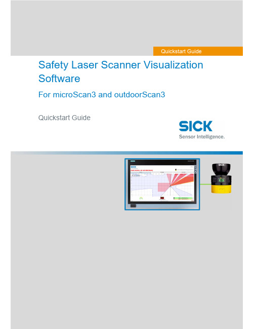
Safety Laser Scanner Visualization SoftwareFor microScan3 and outdoorScan3Quickstart GuideQuickstart GuideInhalt1. Display scanner data in 7 steps (3)Step 1 – Connect Scanner (3)Step 1.1 – Power Supply (3)Step 1.2 – Ethernet Cable (3)Step 2 – Set up Ethernet Connection (4)Step 2.1 – Read out IP address using Safety Designer (4)Step 2.2 – Read out IP address on display of safety laser scanner (4)Step 3 – Download Software (4)Step 4 – Preparing SLS Visualization Software (5)Step 4.1 –Edit “executable” file to correct IP address (5)Step 4.2 – Replace IP address (5)Step 4.3 – Save file (6)Step 5 – Preparing the computer for the network connection. (7)Step 6 – Open the SLS Visualization Software (9)Step 7 – SLS Visualization Software is displayed (9)2. Using the SLS Visualization Software on WinCC – Overview (10)WinCC Professional (TIA Portal) (10)WinCC Advanced (TIA Portal) (11)Quickstart Guide – Safety Laser Scanner Visualization Software This document describes the steps to run the SLS Visualization Software for microScan3 and outdoorScan3.Pre-requisites:Windows PC (Win XP and up).o Note 1: The SLS Visualization Software does not run on Windows CE.W indows CE has reached End of Life Support in 2018; therefore SICK cannotprovide the SLS Visualization Software for Windows CE.o Note 2: Many SIEMENS HMI's using TIA Portal are based on Windows / WinCC → therefore many SIEMENS HMI's are supported.Supported devicesAll microScan3 devices - except all microScan3 Core I/O versionsOnly outdoorScan3 Pro EtherNet IP1. Display scanner data in 7 stepsStep 1 – Connect ScannerFirst, connect the safety laser scanner to the HMI or computer on which the SLS Visualization Software is used.Step 1.1 – Power SupplyConnect scanner to power supply with 24V. Find appropriate cables on .As an example, the following cable can be used for power connection for microScan3 ProPROFINET:Step 1.2 – Ethernet CableConnect safety laser scanner to HMI or computer using an Ethernet cable. Find appropriate cables on . As an example following cable can be used for microScan3 Pro PROFINET :Step 2 – Set up Ethernet ConnectionThe next step is to set up the Ethernet Connection. In order to do this the IP address of the safety laser scanner needs to be known. There are two simple ways to read it out.Step 2.1 – Read out IP address using Safety DesignerOpen Safety Designer, connect to device (e.g. by using USB cable) and see address on pageaddressing.Step 2.2 – Read out IP address on display of safety laser scannerUse the Buttons on the Safety Laser Scanner. (Device Info Network IP address)Step 3 – Download SoftwareClick link to download the SLS Visualization Software:- SICK Internal: Download here:https:///pages/viewpageattachments.action?pageId=393349683&preview=/393349683/393349693/microScan3-VISU-Diagnostics_V1-0.rar- SICK External: receive Secureshare Link by your SICK Contact.When the download is finished open the ZIP file as follows:Unpack ZIP file to afolder of choiceStep 4 – Preparing SLS Visualization SoftwareWhen the file is unzipped, following files should be included:Step 4.1 –Edit “executable” file to correct IP addressThe IP address that is programmed must be edited before starting the THE SLS VISUALIZATION SOFTWARE.Step 4.2 – Replace IP addressA window will open in which the specified IP address must be exchanged by the address of the safety laserscanner. If you do not have this IP address then go back to “Step 2”.Right click on the file "Execute_192_168_1_5.bat " allows editing of the file.Replace the pre-programmed IP address with the actual IP address of the scanner.Step 4.3 – Save fileOnce the IP address is set correctly safe the executable with its new name. The name should include the actual IP addressStep 5 – Preparing the computer for the network connection.Using Windows computers the connection may have to set in the Control panel. See steps below.Open Network andSharing Center.Go to …Ethernet“Go to “Properties”Go to …Internetprotocol, Version 4 (TCP/IPv4)“Enter the IP address andsubnet mask. Subnet mask is the same asthe scanner.Note that this is the IP address ofthe HMI VISU, not of thescanner. Thus: Same subnet, nutdifferent IP address, however insame range. Confirm …OK“.Step 6 – Open the SLS Visualization SoftwareOpen the bat file.Step 7 – SLS Visualization Software is displayedOpen the bat file that was created previously with the actual IP address in itThe VISU tool will open and should automatically connect to the safety laser scanner.2. Using the SLS Visualization Software on WinCC – OverviewWinCC (TIA Portal) is available in different variants WinCC Basic, WinCC Comfort, WinCC Advanced and WinCC Professional. In addition, there are the two runtime systems WinCC Runtime Advanced and WinCC Runtime Professional. The difference between the variants lies primarily in the configurable devices.WinCC Professional (TIA Portal)With WinCC Professional the THE SOFTWARE DIAG tool can be opened with an exe file via a c script. To do this the following code must be written into the script.WinCC Advanced (TIA Portal)To start the HMI VISU DIAG tool the following software is needed on WinCC Advanced: The tool can then be implemented into the WinCC advanced software.The tool can now be displayed via WinCC Advanced.The …diag2“-Button, will start the defined eventHere you can choose at which event an actionshould be executed. Under …Program name“ youhave to link the tool you want to open.。
CLV63x调试介绍

中文
说明
英文 Trigger Source Sensor1,Sensor2 External Input1 External Input2 Command Timer/Tracking Good Read Condition Match1 Condition MultCodes1 Condition TeachIn1
一般不修改 会影响扫描周期,一般不修改
: Daniel Zhao 16
单台条码阅读器参数设置及调试
在Output Control下:(一般要修改,根据实际需要选择)
英文 End of Trigger As soon as possible
End of Label New Label
Single
中文 触发结束 立即输出 标签结束 新标签 单次输出 多次输出 读到条码 满足条件Match1 满足条件 TeachIn1 满足条件 TeachIn2
扫描器与PC连接电缆示意图
•确认电缆连接无误后,通过SOPAS_ET软件(可以通过SICK网站或者SICK公司获
得最新版本)通过RS232串口连通扫描器,当连接正确时软件下方会显示扫描 器型号以及通讯方式和当前状态,如下图所示:
这时就表示扫描器与PC建立了正确 的连接可以进行设置和调试工作。
SICK China : Confidential : Daniel Zhao 9
Start配置 要求传感器为PNP型输出,输出 传感器输入,高电平 触发,激光打开 为高电平是触发。 指令触发 自动触发 CAN网触发 总线触发 自动触发 通常为串口指令 周期性的打开激光,一般用于诊 断 CAN网中其它站提供触发信号 命令通过总线触发扫描头 激光常亮,监测到条码后读码
中文 Stop 配置 触发源条件变化 同Start配置中一致
SICK条码阅读器
广州市施克传感器有限公司
完成接线后需要将网络中的第一个接线盒和最后一个 接线盒的 S2(CAN-Term)开关置于 ON 的位置,也就是打开 CAN 网络的终端电阻。扫描器之间的 CAN 总线的网络连线需 要采用屏蔽双绞线。
扫描器 CAN 网络电气连接图
ୋ 7 䔍 38 䔍
条码质量设置(Codelabel Quality): 一般设为 Standard,如条码黑白对比度太 小,选用 Low contract;若有斑点,选用 Speckled。
ୋ 10 䔍 38 䔍
广州市施克传感器有限公司
在 Reading Conf.-Distance Con 下: (一般要修改,根据实际安装距离)
采用带有屏蔽的通信电缆。
ୋ 5 䔍 38 䔍
广州市施克传感器有限公司
注: CDB 接线盒到 PC 的 RS232 电缆需要采用带有屏蔽的通信 电缆,电缆长度建议不要超过 10m。
2.2 多台扫描器通过 CAN 总线方式连接 如果需要使用多台扫描器组成 CAN 总线网络的时候,则需要按照以下方式进
ୋ 15 䔍 38 䔍
广州市施克传感器有限公司
在 Code Confi.下:(一般要修改,根据实际需要选择)
英文 Symbologies Decoder
中文 条码类型 解码方式
Number of Codes Code position
条码数量 条码位置
Min. distance between Labels Symbology Parameters
条码之间最小距离
对已选条码类型的 参数做具体设置
说明 在相应码型前打钩,可多选 可选标准型或智能型(SMART, 可提高对损坏、倾斜或有污点 条码的阅读率,但反应较慢) 设定一次读取的条码数量 若选择比较,满足最小距离条 件的位置不同的条码将作为 新条码读入
SICK信息系统用户手册说明书

User manual: Information systemThis document describes the usage of SICK’s information system / reporting system in Pool4Tool. This system provides KPIs and reports which can be used by both SICK and its suppliers.User manual: Information system (1)1.Introduction (2)2.Accessing the information system (3)2.1.For SICK employees (3)2.2.For suppliers (3)3.Functions in the information system (4)3.1.navigation (4)3.2.Report types (4)3.2.1.Charts (4)3.2.2.Data table (5)3.3.Select data (setting filters) (5)3.4.Printing data (7)3.5.Exporting data (Excel) (8)1. IntroductionThe information system provides KPIs to measure and control the procurement processes of SICK.2.1. For SICK employeesYou can find the information system in Pool4Tool under CRM / SRM and then information system. https:///login.php2.2. For suppliersSuppliers can find the information system at the bottom of the menu-box on the left side of the entry page at the SICK supplier portal. https:///portal/sick/login.php3.1. navigationTo open a specific report, please select it in the menu-box.3.2. Report typesTwo types of reports can be found in the information system.3.2.1. ChartsCharts can be identified by the blue symbol (e. g. turnover development) – data will be displayed in graphical format (bar chart, line chart…)3.2.2. Data tableReports of this type display data in a table format and can provide more detailed information than charts. This data can be downloaded to Excel in order to perform further analysis (see chapter 3.4).3.3. Select data (setting filters)For each report a filter is available. This filter allows you to adapt the displayed data to your current requirements (e. g. turnover of supplier X, delivery performance of material group Y…). As long as no filter is defined, all available data will be displayed.By default, the filter is invisible in order to provide more space for the reporting data. In order to show the filter, please click on the plus symbol in the filter box (see red square in previous picture).Now it is possible to define a combination of filter criterias. Use the button “Display” to activate your filter. The following filter types are available:•Single selection (e. g. Division): Select one value in a list•Multiple selection (e. g. Warengruppe): Select one or several values in a list (use Ctrl + MouseClick or Shift + MouseClick).•Free filter (e.g. Lieferantennummer): Any value can be entere as filter criteria. To define more than one value, a semicolon can be used. Use …53052;53011“ to display all which contains either 53052 or 53011 (or both).•Date filter (e.g. Rechnungsdatum): A period of time can be selected. The green icons help you to select a valid date.Some hints:•All filters are used as so called LIKE-filters (asterix search): If you search for supplier name …test“, suppliers like “abctest” oder “testabc” will be found.•Use the reset button to delete all defined filter criterias.•To reset only on filter criteria, please delete its value or select --- in the provided list.•Filter criteria will be saved if you change from one report to another (as long as the filter field is also available in the other report).As soon as you click on “Display”, the filter will be closed and the displayed data will be adapted to the defined filter. You can see the filter criterias in the blue box above the data.3.4. Printing dataYou can use the function “Print” of your web browser.Alternatively, you can right click on a certain chart to convert it to an image or to print it directly.3.5. Exporting data (Excel)Reports of the type “data table” provide an Excel icon on the top right corner. Click on it to download the table to Excel.。
SICKCLV6xx扫码器器调试方法和步骤(Profinet)TIA博途版

SICKCLV6xx扫码器器调试⽅法和步骤(Profinet)TIA博途版CLV6xx _PROFINET 中⽂调试⼿册 TIA博途版部门:类型:编写⼈:⽇期:版本:⽬录1.SOPAS调试软件设置 (3)1.1.激活Profinet功能 (3)1.2.配置IP地址 (3)2.TIA博图配置 (4)2.1.安装GSDML⽂件 (4)2.2.硬件组态 (5)3.开始数据通讯 (7)3.1.设置SOPAS触发⽅式 (7)3.2.⾸先利⽤串⼝调试⼯具进⾏读取测试 (8)3.3.监控PLC变量表 (8)4.安装SICK FB功能块 (9)4.1.安装FB功能块 (9)4.2.添加功能块 (10)5.功能块介绍 (12)5.1.“HWInputIdent” (12)5.2.“HWInputlength”和“HWOutputlenth” (13)5.3.“Tout” (13)5.4.“CANId” (13)5.5.接下去的都为控制字部分: (14)5.6.控制字的时序图 (14)6.使⽤功能块 (15)6.1.SOPAS配置: (15)6.2.读取条码 (16)1.SOPAS调试软件设置1.1.激活Profinet功能输⼊设备名称,并且需要和PLC内的⼀致:注意事项:Device Name是关键,在西门⼦博途中的设置必须和SOPAS中的名字⼀致,如果不⼀致会导致PLC硬件报错红灯闪烁,系统⽆法建⽴PN连接。
1.2.配置IP地址IP地址如果通过设备单独设置,那么设置成与PLC同⼀个⽹段。
2.TIA博图配置2.1.安装GSDML⽂件2.1.1.打开SICK官⽹,下载对应产品对应的GSDML⽂件和FB功能块;本测试采⽤的是基于 TIA(博途)的西门⼦ S7-1200,下载链接如下:2.1.2.安装GSDML⽂件,添加ProfiNet设备到⽹络上;在⼯具栏⾥找到“选项”→“管理通⽤站描述⽂件”,将先前下载的GSDML⽂件导⼊。
西克(SICK)LECTOR620操作手册_中文版
LECTOR620中文操作手册安装距离和角度扫描器的安装距离是指从扫描器的窗口到条码表面的距离。
每种条码的阅读距离都不同,因此安装过程中阅读距离的确定需要查阅相关型号的技术参数。
例如,对于0.5mm分辨率的条码,其最大的视野范围是175mm×112mm(如右图),对应最大视野范围的安装高度为260mm为了避免条码表面对红光直接的反射,条码阅读器一般不采取垂直于条码表面的安装方式,应倾斜20°安装软件操作步骤(1)首先打开SOPAS 软件,一般安装SOPAS后会出现两个软件图标,一个是SOPAS,一个是SOPAS Single Device,两个是同一个软件,不同的是界面排版不同,推荐使用SOPAS Single Device界面版本(2)进入以下画面,会自动搜寻出两个设备,两个所不同是端口号,一个是以太网主口2112,一个是以太网辅口2111,推荐选择2112(3)若搜寻设备的结果如下图则说明扫描枪IP地址与电脑IP地址不一致,可修改电脑IP或扫描枪IP,注意修改时要保证扫描枪和电脑IP地址前三段一致,最后一段不同,同时保证子网掩码相同(4)修改扫描枪IP地址时,可选自动获取或者使用固定IP,推荐使用固定IP地址用于调试和通讯(5)出现选择画面,勾选尾缀为2112的扫描枪,点击继续,即可进入软件主界面。
(6)进入主界面,现处于运行模式Operation ,界面如下图:(7)调试时切换到编辑模式,点击Edit ,此时读码器连续拍照,光源一致闪烁,显示实时图像,右侧有8电脑IP 地址扫描枪IP 地址个参数栏,常用的参数栏如下:(8)第一项参数Camera & Illumination 相机和光源设定:调试要点:图像一定要清晰,根据实际情况调节曝光时间,增益和对比度获取稳定的阅读效果(9)第二项参数Codes 条码设定:本产品可同时阅读一维条码,二维PDF417码,二维码,根据所要读取的条码种类勾选相应的码制1. 相机和光源设定2. 条码种类设定3. 触发设定4. 通讯接口和信号输出设定5. 输出格式设定(10)以上图像和条码设定也可通过自学习方式完成,点击Auto Setup自动设定,如下:(11)点击后显示如下画面,首先调整Reading Distance阅读距离使图像聚焦清晰,调整Shutter time曝光时间使图像变亮,在条码的位置拖动鼠标画一个区域覆盖条码,点击继续进入自学习过程(12)学习成功后如下画面,点击继续;若自学习不成功则会显示Fail,此时可进入软件手动调整参数(13)显示如下实时阅读画面,点击结束完成自学习(14)第三项Trigger & Digital Input触发和输入信号设定,本产品触发读码器方式有很多种,常用是Sensor/Input 1,由外部接入开关量信号触发读码器开始阅读,结束阅读也有多种方式并且可以组合使用,满足任意条件均可结束阅读(15)第四项Interface & Digital Output 通讯接口和信号输出设定,常用通讯方式是串口RS232和以太网(16)串口通讯设置:点开Serial Host ,通常情况下无需修改参数,默认参数即可,但要注意波特率Baud rate 要和上位机一样触发开始串口 输出信号(17)以太网通讯设置:点开Ethernet Host,a.当需要设扫描枪为服务器端时则选择Server模式,上位机需要输入扫描枪的IP地址和端口号,其中端口号可根据需要修改,默认为2112;b.当需要设定扫描枪为客户端时则选择Client模式,此时需要输入上位机的IP地址和端口号,其中端口号可根据需要修改,默认为2112(18)扫描枪支持两路输出,以设定Output/Result 1输出信号为例,可设定成功读取Good Read或者读不到No Read时输出信号,输出电压默认为24V PNP型,也可通过反转功能变成0V有效,NPN型(19)第五项Data Processing 数据处理设定,扫描枪输出的数据格式可根据需要灵活编辑,点击Data Processing 中的Output Format1选项,默认输出格式如下图即“如果成功读取则输出条码内容,否则输出NoRead ”,可以在此处编辑,例如在条码后加入回车换行(20)数据输出格式也可通过设置向导Wizard 完成,点击Wizard 选择好所要的格式后点击继续(21)设定所需要读的码的最多和最少数量,点击继续码可在条码之间加分隔符Code Separator,如空格,斜杠等,设置完成后点击结束(23)设定完成后切换为运行模式Operation ,点击Operation 即可(24)点击参数下载和永久保存,将参数保存在扫描器中:(25)本软件自带数据接收终端,显示所读取到的数据,可用于调试串口和以太网通讯是否正常,点击数据终端Terminal ,以以太网通讯为例操作如下:若是串口则选择用户自定义连接。
SICKCLV440条码阅读器调试手册[1]..
![SICKCLV440条码阅读器调试手册[1]..](https://img.taocdn.com/s3/m/c73e8762ddccda38376baf25.png)
13
27
广州市施克传感器有限公司
在 Data Strings 下: (一般不要修改,有输出格式要求的,可根据实际需要选择) 英文 Output Format 中文 输出格式 说明 Header:头符 Code-Info/Sep.:分割符 Terminator:结尾符 分条码前、条码后两种 决定条码的那一部分内容可输 出,若不选则全部输出 若要求输出的字符串某位置无 效,就用该码代替 可选择分割符、 错误字符串两者 的任意组合 Char. Count:字符数 可设置输出间隔时间
Free:指条码的长度是随意的,只要是这类条码都识别。 Fixed:指条码的长度是固定的,跟此长度不同的不识别。
12
27
广州市施克传感器有限公司
在 Host Interf.下:
英文 Destination of result data strings Data Format Buffer Output Interface Protocol Standard (SICK) Protocol Time-out XON/XOFF Block Check
Invert Output Beeper Pulse Width References Limits
10
27
广州市施克传感器有限公司
在 Match Code Parameters 下: (一般此参数不用,针对有需要条码比较的场合使用) 英文 Code #1--#5 中文 匹配条码#1-#5 说明 可指定条码类型及内容;若选 Not relevant,是指不管条码类 型。 若不选, 匹配结果不影响串口输 出 有动态匹配、 不含医药码固定匹 配、含医药码固定匹配三种
8
27
广州市施克传感器有限公司
- 1、下载文档前请自行甄别文档内容的完整性,平台不提供额外的编辑、内容补充、找答案等附加服务。
- 2、"仅部分预览"的文档,不可在线预览部分如存在完整性等问题,可反馈申请退款(可完整预览的文档不适用该条件!)。
- 3、如文档侵犯您的权益,请联系客服反馈,我们会尽快为您处理(人工客服工作时间:9:00-18:30)。
图中所示为不同类型条码阅读器的安装角度,单线式和多线式阅读器安装 时出射光线和条码表面保持 105 度的倾角。对于摆动镜式的阅读器安装时取阅读 器的侧面和摆角的平分线为 105 度夹角。
第 3 页 共 36 页
说明 定义输出条码内容格式
定义通讯参数
输出内容包含诊断信息
Read Diagnostics:通过辅口监视所阅读条码的信息,如条码类型、长度、位置
等参数。
Monitor Host Interface:通过辅口监视主口(RS232/422)数据,即跟主口相
注: CDB 接线盒到 PC 的 RS232 电缆需要采用带有屏蔽的通信 电缆,电缆长度建议不要超过 10m。
第 7 页 共 36 页
广州市施克传感器有限公司
2.2 多台扫描器通过 CAN 总线方式连接 如果需要使用多台扫描器组成 CAN 总线网络的时候,则需要按照以下方式进
行接线。扫描器通过 CAN H(CDB420 为 11,21 端子,CDB620 为 30,40 端子) 和 CAN L(CDB420 为 31,41 端子)两条总线电缆进行连接,如果扫描器采用不 同电源供电时,则需要将 GND(CDB420 为 13,23 端子,CDB620 为 32,42 端子) 相连,另外为了提高线路传输质量,需要将电缆的屏蔽层与 Shield(6,7 端子) 相连。
Multiread:重复次数,默认为 3,1-99 可选。速度越快,设定重复次 数越少。
Free:指条码的长度是随意的,只要是这类条码都识别。 Fixed:指条码的长度是固定的,跟此长度不同的不识别。
第 17 页 共 36 页
广州市施克传感器有限公司
在 Serial 下: (一般要修改,根据实际需要选择)
条码质量设置(Codelabel Quality): 一般设为 Standard,如条码黑白对 比度太小,选用 Low contract;若有斑点,选用 High Speckle。
最小的条码位置(Minimum Reading Angle):条码在红色激光线中所处 的最小位置,最小值为 0,一般条码应放在中间位置,即 CP=50
英文 Symbologies Minimum Maximum Code distance
中文 条码类型 最少条码数量 最多条码数量 条码之间最小距离
说明 在相应码型前打钩,可多选 最少需要读出的条码数量 最多需要读出的条码数量 用以区分相同内容的多个条码
第 16 页 共 36 页
广州市施克传感器有限公司
广州市施克传感器有限公司
1.3 光电开关的安装方法 通常状况下条码阅读器都采用光电开关来提供触发信号源,因此光电开关的
正确安装也非常重要。下图所示为光电开关的安装方法。
如图所示,我们设定条码边缘到货箱边缘的距离为 a,光电开关到条码阅读 器的距离为 b。
第一种情况,当采用沿传送方向先安装条码阅读器后安装光电开关的方式 时,则必须保证 b<a 成立。
完成接线后需要将网络中的第一个接线盒和最后一个 接线盒的 S2(CAN-Term)开关置于 ON 的位置,也就是打开 CAN 网络的终端电阻。扫描器之间的 CAN 总线的网络连线需 要采用屏蔽双绞线。
第 8 页 共 36 页
广州市施克传感器有限公司
扫描器 CAN 网络电气连接图
第 9 页 共 36 页
M
电机控制器
计算机
白 蓝黑
棕
色 色色
色
VL18 光电 开关
如若使用 CDB620,则接线如下图所示:
第 5 页 共 36 页
广州市施克传感器有限公司
注: CDB 接线盒到 RS232-422 转换器之间的 RS422 电缆需要 采用带有屏蔽的通信电缆。
第 6 页 共 36 页
广州市施克传感器有限公司
广州市施克传感器有限公司
主要参数设置
第 11 页 共 36 页
在 Reading Configuration.下:(一般不用修改)
广州市施克传感器有限公司
频率设置(Scanning Frequency): 条码阅读器扫描频率(Scanning Frequency)概念:扫描频率是指扫描器内部旋转镜的转动速度。扫描频率的设定 与条码分辨率(Module Width)、阅读距离以及被扫描物体(条码)的运动速度 有关。具体的设定原则如下: (1)、条码分辨率越小,扫描频率应设定低; (2)、阅读距离越远,扫描频率应设定越低; (3)、物体(条码)运动速度越快,扫描频率应越高。
最大的条码位置(Maximum Reading Angle):条码在红色激光线中所处 的最大位置,最大值为 100。 在 Parameter-Reading Configuration-Object Trigger Control 下:(一般要 修改,根据实际触发方式选择)
第 12 页 共 36 页
OFF ON
输出信号为+24V,
最大电流100mA
13 16
14
GND Result1 T+
S3
ON
CDB420-001
OFF
CDB420-001接线端子
15 24 25 26 17 27 28
29
R+ T- R- GND SGND SGND Sensor1 +24V
蜂鸣器及报警灯 继电器
R+ T+ R- T- GND RS422-RS232转换器
若连接失败,请检查通信电缆是否连接正确, 若为以太网连接,请检查网线是否有问题,本机 IP 是否设置有问题? (192.168.0.2) 若为串口连接,请检查针脚是否有损坏,接线是否正确? RxD → TxD,TxD → RxD,GND → GND .
3、下图为菜单工具栏说明。
第 10 页 共 36 页
第二种情况,当采用沿传送方向先安装光电开关后安装条码阅读器的方式 时,则必须保证 b<a 成立。
第 4 页 共 36 页
2、条码阅读器的电气连接
广州市施克传感器有限公司源自2.1 单台扫描器电气连接方式:
如若使用 CDB420,则接线如下图所示:
+
24V直流电源
-
SICK条码 扫描器
+24 DC
S1
GND
3、单台条码阅读器参数设置及调试
广州市施克传感器有限公司
1、SICK 扫描器的调试和参数设置一般通过扫描器的 Terminal 端口进行。也就 是通过接线盒 CDB420 中的 AUX Interfac(e 9 针插头)将扫描器与计算机相连接。 连接电缆的选用 2-3 交叉串口通信电缆,电缆的连线如下图所示,
发,激光打开
高电平是触发。
指令触发 自动触发 CAN 网触发 总线触发 自动触发
通常为串口指令 周期性的打开激光,一般用于诊断 CAN 网中其它站提供触发信号 命令通过总线触发扫描头 激光常亮,监测到条码后读码
第 13 页 共 36 页
英文
Trigger Source Sensor1,Sensor2 External Input1 External Input2 Command Timer/Tracking Good Read Condition Match1 Condition MultCodes1 Condition TeachIn1
广州市施克传感器有限公司
英文
Sensor1,Sensor2 External Input1 External Input2 Command Auto Cycle CAN Fieldbus Input Free running
中文
说明
Start 配置
传感器输入,高电平触 要求传感器为 PNP 型输出,输出为
在 Output Control 下:(一般要修改,根据实际需要选择)
第 14 页 共 36 页
英文 End of Trigger As soon as possible
End of Label New Label
Single
Multiple
Good Read Condition Match1 Condition TeachIn1 Condition TeachIn2
中文 触发结束 立即输出 标签结束 新标签 单次输出 多次输出 读到条码 满足条件 Match1 满足条件 TeachIn1 满足条件 TeachIn2
广州市施克传感器有限公司
说明
Evaluation Condition 中定义 Evaluation Condition 中定义 Evaluation Condition 中定义
中文 Stop 配置
触发源条件变化 同 Start 配置中一 致
时钟或位置 成功读码 匹配条件满足 读码数量满足 满足 TeachIn1 条件
广州市施克传感器有限公司
说明 例如 Sensor1 触发信号消失
通过时间或者编码器脉冲控制 见 Evaluation Condition 中定义 见 Evaluation Condition 中定义 见 Evaluation Condition 中定义
英文 Output Format #1
Baudrate,Stopbits Databits/Parity/Hardware Reading Diagnosis Monitor Serial Host RDT400 Protocol
中文 数据格式(在 Output Format 中定义) 波特率,停止位,数据 位,奇偶校验位。。 阅读诊断 监视主口 直接输出到 RDT 工具
第 2 页 共 36 页
广州市施克传感器有限公司
1、条码阅读器的安装步骤
