数码管型号
数码管3461as参数

数码管3461as参数
一、数码管概述
数码管是一种常用的显示器件,它可以将数字信息以可视化的形式展示给用户。
数码管的应用范围广泛,从电子产品到工业设备,都可以看到它的身影。
在众多数码管型号中,3461as是一款具有较高性价比的数码管。
二、数码管3461as的参数特性
1.显示位数:3461as数码管为四位显示,可以显示0-9的数字。
2.段码:3461as数码管采用共阳极设计,具有较少的引脚,便于连接。
3.尺寸:3461as数码管的尺寸较为紧凑,适合各种有限空间的应用。
4.工作电压:3461as数码管的工作电压范围为4.5V-6.5V,适应不同电源环境。
5.功耗:3461as数码管的功耗较低,有利于延长设备的使用寿命。
6.稳定性:3461as数码管具有较高的稳定性,可长时间运行。
三、3461as数码管的应用领域
1.电子产品:3461as数码管广泛应用于各种电子产品,如计时器、计数器、电子钟表等。
2.工业设备:由于3461as数码管具有较高的稳定性和可靠性,它也成为许多工业设备的首选显示器件。
3.汽车电子:3461as数码管可用于汽车电子设备,如里程表、转速表等。
4.医疗设备:3461as数码管在医疗设备中的应用也越来越广泛,如心电图仪、血压计等。
四、总结
3461as数码管凭借其优异的性能和实用的特性,在众多显示器件中脱颖而出。
无论是电子产品、工业设备,还是汽车电子和医疗设备,3461as数码管都能发挥出良好的显示效果。
LED数码管数码表+proteus元件库对照
共阳极数码管的公共阳极接+5V,当各段阴极上的电平为“0”时,该段点亮,电平为“1”时,该段熄灭。
CRYSTAL 晶振
元件名称 中文名 说明
7407 驱动门
1N914 二极管
74Ls00 与非门
74LS04 非门
74LS08 与门
74LS390 TTL 双十进制计数器
LED数码码管:
7SEG-MPX4-CC 四个公阴二极管显示器 1234 是阴公共端
7SEG-MPX8-CC 八个公阴二极管显示器 12345678 是阴公共端
7SEG-MPX4-CA 四个公阳二极管显示器 1234 是阳公共端
7SEG-MPX8-CA 八个公阳二极管显示器 12345678 是阳公共端
RESISTORS.LIB 包括 电阻
FAIRCHLD .LIB 包括FAIRCHLD 半导体公司的分立器件
LINTEC.LIB 包括 LINTEC公司的运算放大器
NATDAC.LIB 包括 国家半导体公司的数字采样器件
NATOA.LIB 包括 国家半导体公司 的运算放大器
TECOOR.LIB 包括TECOOR公司的 SCR 和TRIAC
INDUCTOR3 可调电感
JFET N N沟道场效应管
JFET P P沟道场效应管
LAMP 灯泡
LAMP NEDN 起辉器
LED 发光二极管
METER 仪表
MICROPHONE 麦克风
MOSFET MOS管
MOTOR AC 交流电机
MOTOR SERVO 伺服电机
BELL 铃,钟
BVC 同轴电缆接插件
BRIDEG 1 整流桥(二极管)
7448简介及数码管简介
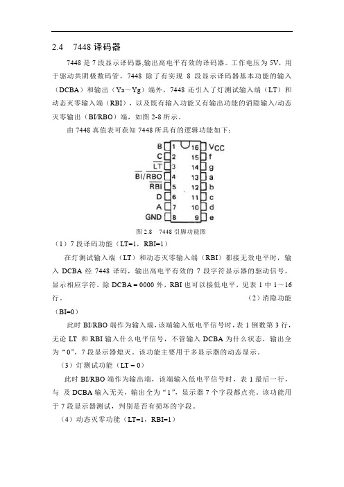
2.4 7448译码器7448是7段显示译码器,输出高电平有效的译码器。
工作电压为5V,用于驱动共阴极数码管,7448除了有实现8段显示译码器基本功能的输入(DCBA)和输出(Ya~Yg)端外,7448还引入了灯测试输入端(LT)和动态灭零输入端(RBI),以及既有输入功能又有输出功能的消隐输入/动态灭零输出(BI/RBO)端,如图2-8所示。
由7448真值表可获知7448所具有的逻辑功能如下:图2.8 7448引脚功能图(1)7段译码功能(LT=1,RBI=1)在灯测试输入端(LT)和动态灭零输入端(RBI)都接无效电平时,输入DCBA经7448译码,输出高电平有效的7段字符显示器的驱动信号,显示相应字符。
除DCBA = 0000外,RBI也可以接低电平,见表1中1~16行。
(2)消隐功能(BI=0)此时BI/RBO端作为输入端,该端输入低电平信号时,表1倒数第3行,无论LT 和RBI输入什么电平信号,不管输入DCBA为什么状态,输出全为“0”,7段显示器熄灭。
该功能主要用于多显示器的动态显示。
(3)灯测试功能(LT = 0)此时BI/RBO端作为输出端,该端输入低电平信号时,表1最后一行,与及DCBA输入无关,输出全为“1”,显示器7个字段都点亮。
该功能用于7段显示器测试,判别是否有损坏的字段。
(4)动态灭零功能(LT=1,RBI=1)此时BI/RBO端也作为输出端,LT 端输入高电平信号,RBI 端输入低电平信号,若时DCBA = 0000,表1倒数第2行,输出全为“0”,显示器熄灭,不显示这个零。
DCB A≠0,则对显示无影响。
该功能主要用于多个7段显示器同时显示时熄灭高位的零。
(5)7448/SN7448译码器0-9真值表如表2.2所示:表2.2 7448/SN7448译码器0-9真值表数码管是一种半导体发光器件,其基本单元是发光二极管。
2.5.1产品分类数码管按段数分为七段数码管和八段数码管,八段数码管比七段数码管多一个发光二极管单元(多一个小数点显示);按能显示多少个“8”可分为1位、2位、4位等等数码管。
5寸数码管规格书

Parameters.
4
50 011 B
1 2 6.50 ( 5 . 0") 1 3 9 . 50 0.8 1 3 0 . 00
69.40
10
11. 8
104.50
F E
A GB
D DeCPlectronics
co.,ltd
xsm
15.90 6.9 ±0.5
ain.asp 5.08*4=20.32
规格书
Specifications
品名 Name
1 位数码管 1 Digit Seven Segments LED Display
型号 Model
发光颜色 Color 8 字高度
“8” Height
总芯片数 Total LED Chips
XSM-S50011A (共阴 Share Cathode)
XSM-S50011B (共阳 Share Anode)
z 冲驱动)功耗率是-0.75mW/℃。产品的工作电流不能大于对应工作温度条件 Ifm 或 Ifp 的 60%。 .s For operation above 25℃,The Ifm Ifp & Pd must be derated,the Current derating is-0.36Ma/℃ for DC w drive and -0.86mA/℃ for pulse drive,the power dissipation is -0.75mW/℃.The product working current ww must not more than the 60% of the Ifm or Ifp according to the working temperature.
1,8
CC4511驱动数码管
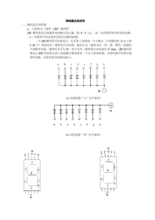
译码器及其应用一、数码显示译码器a、七段发光二极管(LED)数码管LED数码管是目前最常用的数字显示器,图6—5(a)、(b)为共阴管和共阳管的电路,(c)为两种不同出线形式的引出脚功能图。
一个LED数码管可用来显示一位0~9十进制和一个小数点。
小型数码管(0.5寸和0.36寸)每段发光二极管的正向压降,随显示光(通常为红、绿、黄、橙色)的颜色不同略有差别,通常约为2~2.5V,每个发光二极管的点亮电流在5~10mA。
LED数码管要显示BCD码所表示的十进制数字就需要有一个专门的译码器,该译码器不但要完成译码功能,还要有相当的驱动能力。
(a)共阴连接(“1”电平驱动)(b)共阳连接(“0”电平驱动)(c)符号及引角功能图 6-5 LED数码管b.BCD码七段译码驱动器此类译码器型号有74LS47(共阳),74LS48(共阴), CC4511(共阴)等,本电路采用 CC4511 码锁存/七段译码/驱动器。
驱动共阴极LED数码管。
为 CC4511引脚排列图6-6 CC4511 引角排列其中A. B.C. D~ BCD 码输入端a.b.c.d.e.f.g ~译码输出端,输出“1”有效,用来驱动共阴极LED数码管。
—测试输入端, =“0”时,译码输出全为“1”一消隐输入端, =“0”时,译码输出全为“0”LE—锁定端, =“1”时,译码器处于锁定(保持)状态,译码输出保持在 =0时的数值, =0为正常译码。
表6-2为CC4511功能表。
内接有上拉电阻,故只需在输出端与数码管笔段串入限流电阻即可工作。
译码器还有拒伪码功能,当输入码超过1001时,输出全为“0”,数码管熄灭。
表6-2输入输出LE D C B A a b c d e f g 显示字型* * 0 * * * * 1 1 1 1 1 1 1 80 0 1 * * * * 0 0 0 0 0 0 0 消隐0 1 1 0 0 0 0 1 1 1 1 1 1 0 00 1 1 0 0 0 1 0 1 1 0 0 0 0 10 1 1 0 0 1 0 1 1 0 1 1 0 1 20 1 1 0 0 1 1 1 1 1 1 0 0 1 30 1 1 0 1 0 0 0 1 1 0 0 1 1 40 1 1 0 1 0 1 1 0 1 1 0 1 1 50 1 1 0 1 1 0 0 0 1 1 1 1 1 60 1 1 0 1 1 1 1 1 1 0 0 0 0 70 1 1 1 0 0 0 0 1 1 1 1 1 1 80 1 1 1 0 0 1 1 1 1 0 0 1 1 90 1 1 1 0 1 0 0 0 0 0 0 0 0 消隐0 1 1 1 0 1 1 1 0 0 0 0 0 0 消隐0 1 1 1 1 0 0 0 0 0 0 0 0 0 消隐0 1 1 1 1 0 1 1 0 0 0 0 0 0 消隐0 1 1 1 1 1 0 0 0 0 0 0 0 0 消隐0 1 1 1 1 1 1 0 0 0 0 0 0 0 消隐1 1 1 * * * * 锁存锁存在本数字电路实验装置上已完成译码器CC4511和数码管BS202之间的连接.实验时只要接通+5V 电源和将十进制数的BCD码接至译码器的相应输入端A.B.C.D 即可显示0~9的数字。
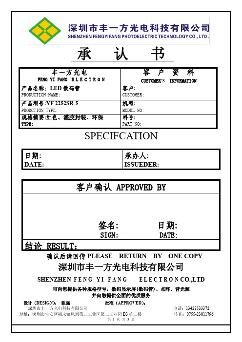
YF2252SR-5
Var
V
*焊接温度(Lead Sodering Temperature):260℃ for 3 seconds *当工作温度高于 25℃时,Ifm,Ifp 和 Id 必须降低;电流降低率是-0.36mA/℃(直流驱动),或-0.86mA/℃ (脉冲驱动)功耗降低率是-0.75mW/℃。产品的工作电流不能大于对应工作温度条件 Ifm 或 Ifp 的 60%。 For operation above 25℃, The Ifm Ifp & Pd must be derated, the Curent derating is –0.36mA/℃ for DC drive and -0.86mA/℃ for Pulse drive, the power dissipation is -0.75mW/℃. The product working current
可向您提供各种规格型号,数码显示屏(数码管)、点阵、背光源 并向您提供全面的优质服务
设计(DESIGN): 张强
批准(APPROVED):
深圳市丰一方光电科技有限公司
地址:深圳市宝安区福永镇凤凰第三工业区第二工业园 B3 栋三楼
第1页共3页
电话:13428533372 传真:0755-23011796
机型:
MODEL NO:
料号:
PART NO:
SPECIFCAER:
客户确认 APPROVED BY
签名:
日期:
SIGN:
DATE:
结论 RESULT:
确认后请回传 PLEASE RETURN BY ONE COPY
深圳市丰一方光电科技有限公司
SHENZHEN F E N G Y I F A N G E L E C T R O N CO.,LTD
5631数码管规格书

5631数码管规格书摘要:1.概述5631数码管2.5631数码管的规格参数3.5631数码管的应用领域4.5631数码管的选购与使用注意事项正文:一、概述5631数码管5631数码管是一种常见的显示器件,广泛应用于各种数字显示场合。
它的命名来源于其型号,其中“56”代表显示屏的尺寸,即直径为5.6毫米;“31”则表示该数码管有31个引脚。
5631数码管具有体积小、显示清晰、功耗低等优点,成为了许多电子设备的首选显示器件。
二、5631数码管的规格参数1.尺寸:直径5.6毫米,高度约4.5毫米。
2.显示位数:共四位数字,每位数字高6.2毫米。
3.数字间距:0.6毫米。
4.字母间距:0.7毫米。
5.工作电压:1.5V-3.0V。
6.工作温度:-20℃-+70℃。
7.存储温度:-40℃-+85℃。
三、5631数码管的应用领域5631数码管广泛应用于各类电子产品,如电子钟表、智能家居、医疗设备、汽车电子等。
由于其体积小、显示效果好,特别适用于需要紧凑型显示方案的设备。
四、5631数码管的选购与使用注意事项1.在选购5631数码管时,应根据实际应用需求选择合适的尺寸和显示位数。
2.注意查看产品的技术参数,如工作电压、工作温度等,确保选购的数码管能满足设备的性能要求。
3.在使用5631数码管时,应确保供电稳定,避免电压波动对显示效果造成影响。
4.注意数码管的散热,长时间高负荷运行可能导致过热损坏。
5.避免在潮湿环境中使用,以免影响数码管的寿命。
总之,5631数码管作为一种常见的显示器件,在众多电子产品中发挥着重要作用。
选购合适的5631数码管并正确使用,可以确保设备的良好性能。
淡水LED数码管型号T7DS说明书
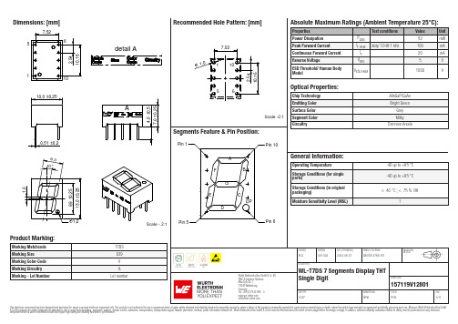
Dimensions: [mm]15detail AScale - 2:1157119V12801Schematic:157119V12801157119V12801157119V12801157119V12801157119V12801157119V12801T e m p e r a t u r eT T T 157119V12801Cautions and Warnings:The following conditions apply to all goods within the product series of Optoelectronic Components of Würth Elektronik eiSos GmbH & Co. KG:General:•This optoelectronic component is designed and manufactured for use in general electronic equipment.•Würth Elektronik must be asked for written approval (following the PPAP procedure) before incorporating the components into any equipment in fields such as military, aerospace, aviation, nuclear control, submarine, transportation (automotive control, train control, ship control), transportation signal, disaster prevention, medical, public information network, etc. where higher safety and reliability are especially required and/or if there is the possibility of direct damage or human injury.•Optoelectronic components that will be used in safety-critical or high-reliability applications, should be pre-evaluated by the customer. •The optoelectronic component is designed and manufactured to be used within the datasheet specified values. If the usage and operation conditions specified in the datasheet are not met, the wire insulation may be damaged or dissolved.•Do not drop or impact the components, the component may be damaged•Würth Elektronik products are qualified according to international standards, which are listed in each product reliability report. Würth Elektronik does not warrant any customer qualified product characteristics beyond Würth Elektroniks’ specifications, for its validity and sustainability over time.•The responsibility for the applicability of the customer specific products and use in a particular customer design is always within the authority of the customer. All technical specifications for standard products also apply to customer specific products.Product specific:Soldering:•The solder profile must comply with the technical product specifications. All other profiles will void the warranty.•All other soldering methods are at the customers’ own risk.Cleaning and Washing:•Washing agents used during the production to clean the customer application might damage or change the characteristics of the optoelectronic component body, marking or plating. Washing agents may have a negative effect on the long-term functionality of the product.•Using a brush during the cleaning process may break the optoelectronic component body. Therefore, we do not recommend using a brush during the PCB cleaning process.Potting:•If the product is potted in the customer application, the potting material might shrink or expand during and after hardening. Shrinking could lead to an incomplete seal, allowing contaminants into the optoelectronic component body, pins or termination. Expansion could damage the components. We recommend a manual inspection after potting to avoid these effects.Storage Conditions:• A storage of Würth Elektronik products for longer than 12 months is not recommended. Within other effects, the terminals may suffer degradation, resulting in bad solderability. Therefore, all products shall be used within the period of 12 months based on the day of shipment.•Do not expose the optoelectronic component to direct sunlight.•The storage conditions in the original packaging are defined according to DIN EN 61760-2.•For a moisture sensitive component, the storage condition in the original packaging is defined according to IPC/JEDEC-J-STD-033. It is also recommended to return the optoelectronic component to the original moisture proof bag and reseal the moisture proof bag again. •The storage conditions stated in the original packaging apply to the storage time and not to the transportation time of the components. Packaging:•The packaging specifications apply only to purchase orders comprising whole packaging units. If the ordered quantity exceeds or is lower than the specified packaging unit, packaging in accordance with the packaging specifications cannot be ensured. Handling:•Violation of the technical product specifications such as exceeding the nominal rated current, will void the warranty.•The product design may influence the automatic optical inspection.•Certain optoelectronic component surfaces consist of soft material. Pressure on the top surface has to be handled carefully to prevent negative influence to the function and reliability of the optoelectronic components.•ESD prevention methods need to be applied for manual handling and processing by machinery.•Resistors for protection are obligatory.•Luminaires in operation may harm human vision or skin on a photo-biological level. Therefore direct light impact shall be avoided. All products are additionally certified as risk groups 0 to 2 according to DIN EN 62471:2008.•In addition to optoelectronic components testing, products incorporating these devices have to comply with the safety precautions given in IEC 60825-1, IEC 62471 and IEC 62778•Please be aware that Products provided in bulk packaging may get bent and might lead to derivations from the mechanical manufacturing tolerances mentioned in our datasheet, which is not considered to be a material defect.Technical specification:•The typical and/or calculated values and graphics of technical parameters can only reflect statistical figures. The actual parameters of each single product, may differ from the typical and/or calculated values or the typical characteristic line.•On each reel, only one bin is sorted and taped. The bin is defined on intensity, chromaticity coordinate or wavelength and forwardWürth Elektronik eiSos GmbH & Co. KGEMC & Inductive SolutionsMax-Eyth-Str. 174638 WaldenburgGermanyCHECKED REVISION DATE (YYYY-MM-DD)GENERAL TOLERANCE PROJECTIONMETHODPLD001.0022023-05-27DIN ISO 2768-1mDESCRIPTIONWL-T7DS 7 Segments Display THTSingle Digit ORDER CODE157119V12801SIZE/TYPE BUSINESS UNIT STATUS PAGEvoltage.•In order to ensure highest availability, the reel binning of standard deliveries can vary. A single bin cannot be ordered. Please contact us in advance, if you need a particular bin sorting before placing your order.•Test conditions are measured at the typical current with pulse duration < 30ms. •Wavelength tolerance under measurement conditions ± 2nm. •Optical intensity tolerance under measurement conditions ±15%. •Forward voltage tolerance under measurement conditions ± 0.2V.These cautions and warnings comply with the state of the scientific and technical knowledge and are believed to be accurate and reliable.However, no responsibility is assumed for inaccuracies or incompleteness.Würth Elektronik eiSos GmbH & Co. KG EMC & Inductive Solutions Max-Eyth-Str. 174638 Waldenburg GermanyCHECKED REVISION DATE (YYYY-MM-DD)GENERAL TOLERANCEPROJECTION METHODPLD001.0022023-05-27DIN ISO 2768-1mDESCRIPTIONWL-T7DS 7 Segments Display THT Single DigitORDER CODE157119V12801SIZE/TYPEBUSINESS UNITSTATUSPAGEImportant NotesThe following conditions apply to all goods within the product range of Würth Elektronik eiSos GmbH & Co. KG:1. General Customer ResponsibilitySome goods within the product range of Würth Elektronik eiSos GmbH & Co. KG contain statements regarding general suitability for certain application areas. These statements about suitability are based on our knowledge and experience of typical requirements concerning the areas, serve as general guidance and cannot be estimated as binding statements about the suitability for a customer application. The responsibility for the applicability and use in a particular customer design is always solely within the authority of the customer. Due to this fact it is up to the customer to evaluate, where appropriate to investigate and decide whether the device with the specific product characteristics described in the product specification is valid and suitable for the respective customer application or not.2. Customer Responsibility related to Specific, in particular Safety-Relevant ApplicationsIt has to be clearly pointed out that the possibility of a malfunction of electronic components or failure before the end of the usual lifetime cannot be completely eliminated in the current state of the art, even if the products are operated within the range of the specifications.In certain customer applications requiring a very high level of safety and especially in customer applications in which the malfunction or failure of an electronic component could endanger human life or health it must be ensured by most advanced technological aid of suitable design of the customer application that no injury or damage is caused to third parties in the event of malfunction or failure of an electronic component. Therefore, customer is cautioned to verify that data sheets are current before placing orders. The current data sheets can be downloaded at .3. Best Care and AttentionAny product-specific notes, cautions and warnings must be strictly observed. Any disregard will result in the loss of warranty.4. Customer Support for Product SpecificationsSome products within the product range may contain substances which are subject to restrictions in certain jurisdictions in order to serve specific technical requirements. Necessary information is available on request. In this case the field sales engineer or the internal sales person in charge should be contacted who will be happy to support in this matter.5. Product R&DDue to constant product improvement product specifications may change from time to time. As a standard reporting procedure of the Product Change Notification (PCN) according to the JEDEC-Standard inform about minor and major changes. In case of further queries regarding the PCN, the field sales engineer or the internal sales person in charge should be contacted. The basic responsibility of the customer as per Section 1 and 2 remains unaffected.6. Product Life CycleDue to technical progress and economical evaluation we also reserve the right to discontinue production and delivery of products. As a standard reporting procedure of the Product Termination Notification (PTN) according to the JEDEC-Standard we will inform at an early stage about inevitable product discontinuance. According to this we cannot guarantee that all products within our product range will always be available. Therefore it needs to be verified with the field sales engineer or the internal sales person in charge about the current product availability expectancy before or when the product for application design-in disposal is considered. The approach named above does not apply in the case of individual agreements deviating from the foregoing for customer-specific products.7. Property RightsAll the rights for contractual products produced by Würth Elektronik eiSos GmbH & Co. KG on the basis of ideas, development contracts as well as models or templates that are subject to copyright, patent or commercial protection supplied to the customer will remain with Würth Elektronik eiSos GmbH & Co. KG. Würth Elektronik eiSos GmbH & Co. KG does not warrant or represent that any license, either expressed or implied, is granted under any patent right, copyright, mask work right, or other intellectual property right relating to any combination, application, or process in which Würth Elektronik eiSos GmbH & Co. KG components or services are used.8. General Terms and ConditionsUnless otherwise agreed in individual contracts, all orders are subject to the current version of the “General Terms and Conditions of Würth Elektronik eiSos Group”, last version available at .Würth Elektronik eiSos GmbH & Co. KGEMC & Inductive SolutionsMax-Eyth-Str. 174638 WaldenburgGermanyTel. +49 (0) 79 42 945 - 0*******************CHECKED REVISION DATE (YYYY-MM-DD)GENERAL TOLERANCE PROJECTIONMETHODPLD001.0022023-05-27DIN ISO 2768-1mDESCRIPTIONWL-T7DS 7 Segments Display THTSingle Digit ORDER CODE157119V12801SIZE/TYPE BUSINESS UNIT STATUS PAGE0.39"eiPal PCN11/11This electronic component has been designed and developed for usage in general electronic equipment only. This product is not authorized for use in equipment where a higher safety standard and reliability standard is especially required or where a failure of the product is reasonably expected to cause severe personal injury or death, unless the parties have executed an agreement specifically governing such use. Moreover Würth Elektronik eiSos GmbH & Co KG products are neither designed nor intended for use in areas such as military, aerospace, aviation, nuclear control, submarine, transportation, transportation signal, disaster prevention, medical, public information network etc.. Würth Elektronik eiSos GmbH & Co KG must be informed about the intent of such usage before the design-in stage. In addition, sufficient reliability evaluation checks for safety must be performed on every electronic component which is used in electrical circuits that require high safety and reliability functions or performance.。
数码管3461as参数
数码管3461as参数数码管是一种常见的数字显示器件,广泛应用于各种电子设备中。
其中,数码管3461as是一种常见的型号,具有一定的参数特性。
本文将对数码管3461as的参数进行研究分析,探讨其在实际应用中的表现和优劣势。
一、数码管3461as的基本参数数码管3461as是一种共阳极七段数码管,具有4位显示功能。
其尺寸为0.56英寸,适用于常见的数字显示需求。
数码管3461as的发光颜色为红色,工作电压为2.2V,工作电流为20mA。
此外,数码管3461as具有高亮度、低功耗、长寿命等特点。
二、数码管3461as的性能优势1. 高亮度:数码管3461as采用优质发光二极管芯片,具有高亮度的显示效果,即使在光线较暗的环境下也能清晰显示数字。
2. 良好的可靠性:数码管3461as经过严格的质量控制和测试,具有较高的可靠性和稳定性,长期使用不易出现故障。
3. 低功耗:数码管3461as采用先进的节能技术,功耗较低,可有效节约能源,符合节能环保的要求。
4. 易于控制:数码管3461as具有七段显示功能,易于接口控制,可通过微控制器等设备实现数字显示。
5. 良好的视觉效果:数码管3461as发光颜色为红色,显示效果鲜明,具有良好的视觉效果,适用于各种显示场景。
三、数码管3461as的应用场景数码管3461as广泛应用于各种电子设备中,如电子钟、计时器、电子秤等。
其高亮度、稳定性和易控制性使其在数字显示领域具有重要的应用意义。
下面以几个典型的应用场景为例进行介绍。
1. 数码时钟:数码管3461as可以应用于电子时钟中,显示时、分、秒等时间信息。
通过微控制器的程序设计,可以实现精准的时间显示功能。
2. 计数器:数码管3461as可作为计数器的显示部件,用于显示计数值。
在工业生产、实验室等场合,计数器是一种常见的计数设备。
3. 电子秤:数码管3461as适用于电子秤中的重量显示,可以直观地显示称重结果,便于用户准确读取重量信息。
数码管3461as参数
数码管3461AS参数1. 引言数码管是一种常见的数字显示设备,用于在各种电子设备中显示数字和字符。
3461AS是一种常见的数码管型号,本文将详细介绍3461AS数码管的参数。
2. 3461AS数码管概述3461AS数码管是一种共阳极的七段LED数码管,由7个发光二极管(LED)组成。
每个发光二极管代表一个段,总共有7个段可以控制。
这些段可以通过外部电路以不同的方式被点亮,从而显示不同的数字和字符。
3. 参数说明3.1 尺寸•长度:10mm•宽度:20mm•高度:7.6mm3.2 发光颜色•常见颜色:红色、绿色、黄色等3.3 显示类型3461AS数码管采用七段式显示,可以显示0-9的数字以及A-F的字母。
每个数字或字母都可以通过点亮或熄灭相应的段来实现。
3.4 输入电流3461AS数码管需要输入电流来点亮LED。
通常情况下,正常工作时的典型输入电流为20mA。
3.5 工作电压3461AS数码管的工作电压通常为2V-2.5V。
在正常工作时,应确保输入电压稳定在这个范围内,以保证数码管正常亮度和显示效果。
3.6 亮度亮度是数码管显示效果的一个重要参数。
3461AS数码管通常有不同的亮度级别可供选择。
较高的亮度级别可以使数字或字符更加清晰可见,但同时也会增加功耗。
3.7 视角视角是指观察数码管时能够看到清晰图像的最大角度范围。
3461AS数码管通常具有广泛的视角范围,可以从多个角度观察到清晰的数字和字符。
3.8 工作温度3461AS数码管的工作温度通常在-40°C到85°C之间。
在超出这个温度范围时,可能会影响数码管的性能和寿命。
3.9 光强衰减随着使用时间的增加,LED发光强度可能会逐渐降低。
3461AS数码管通常具有较低的光强衰减率,可以保持较长时间的高亮度显示效果。
4. 应用领域3461AS数码管广泛应用于各种电子设备中,包括但不限于以下领域: - 电子计算器 - 温度计 - 时钟和计时器 - 电子测量仪器 - 数字显示面板5. 总结本文详细介绍了数码管3461AS的参数,包括尺寸、发光颜色、显示类型、输入电流、工作电压、亮度、视角、工作温度和光强衰减。
数码管型号规格

8字高度
图片
尺寸
规格书
备注
JM-S02041A-B
英寸 /5.00mm
×8
规格书
时钟点亮
JM-S02541A-B
英寸 /6.20mm
36×11
规格书
时钟点亮
JM-S02542A-B
英寸 /6.20mm
20×8
规格书
JM-S02543A-B
英寸 /6.20mm
24×10
规格书
JM-S02841A-B
40×14
规格书
时钟点亮
JM-S03941M-N
英寸 /9.90mm
40×14
规格书
时钟点亮
JM-S03943A-B
英寸 /9.90mm
39×14
规格书
JM-S03944A-B
英寸 /10.00mm
×
规格书
温度点
JM-S04041A-B
英寸 /10.16mm
×16
规格书
时钟点亮
JM-S04042A-B
×
规格书
JM-S05041A-B
英寸 /12.70mm
×19
规格书
JM-S05241A-B
英寸 /13.20mm
×
规格书
JM-S05441A-B
英寸 /13.80mm
48×20
规格书
JM-S05641A-B
英寸 /14.20mm
×19
规格书
JM-S05641E-F
英寸 /14.20mm
×19
规格书
JM-S05643A-B
英寸 /7.10mm
×
规格书
时钟点不亮
JM-S02841C-D
国产LED数码管的型号命名
数码管是一种半导体发光器件,其基本单元是发光二极管。
【数码管的分类】数码管按段数分为七段数码管和八段数码管,八段数码管比七段数码管多一个发光二极管单元(多一个小数点显示);按能显示多少个“8”可分为1位、2位、4位等等数码管;按发光二极管单元连接方式分为共阳极数码管和共阴极数码管。
共阳数码管是指将所有发光二极管的阳极接到一起形成公共阳极(COM)的数码管。
共阳数码管在应用时应将公共极COM接到+5V,当某一字段发光二极管的阴极为低电平时,相应字段就点亮。
当某一字段的阴极为高电平时,相应字段就不亮。
共阴数码管是指将所有发光二极管的阴极接到一起形成公共阴极(COM)的数码管。
共阴数码管在应用时应将公共极COM接到地线GND 上,当某一字段发光二极管的阳极为高电平时,相应字段就点亮。
当某一字段的阳极为低电平时,相应字段就不亮。
【数码管的驱动方式】数码管要正常显示,就要用驱动电路来驱动数码管的各个段码,从而显示出我们要的数字,因此根据数码管的驱动方式的不同,可以分为静态式和动态式两类。
①静态显示驱动:静态驱动也称直流驱动。
静态驱动是指每个数码管的每一个段码都由一个单片机的I/O端口进行驱动,或者使用如BCD码二-十进制译码器译码进行驱动。
静态驱动的优点是编程简单,显示亮度高,缺点是占用I/O端口多,如驱动5个数码管静态显示则需要5×8=40根I/O端口来驱动,要知道一个89S51单片机可用的I/O端口才32个呢:),实际应用时必须增加译码驱动器进行驱动,增加了硬件电路的复杂性。
②动态显示驱动:数码管动态显示接口是单片机中应用最为广泛的一种显示方式之一,动态驱动是将所有数码管的8个显示笔划"a,b,c,d,e,f,g,dp"的同名端连在一起,另外为每个数码管的公共极COM增加位选通控制电路,位选通由各自独立的I/O线控制,当单片机输出字形码时,所有数码管都接收到相同的字形码,但究竟是那个数码管会显示出字形,取决于单片机对位选通COM端电路的控制,所以我们只要将需要显示的数码管的选通控制打开,该位就显示出字形,没有选通的数码管就不会亮。
共阴极数码管型号

共阴极数码管型号共阴极数码管型号介绍概述共阴极数码管是一种常见的电子显示组件,常用于数字显示、时钟、计时器和计数器等应用中。
本文将介绍几种常见的共阴极数码管型号,包括它们的结构、特性和应用范围。
一、74LS47型共阴极数码管1. 结构:74LS47型共阴极数码管由7个发光二极管组成,每个二极管对应一个数字(0-9)。
它们的阴极连接在一起,所以称为共阴极。
数码管上还有一个小数点显示器。
2. 特性:74LS47型数码管采用共阴极极性,电流流过各个二极管,可以显示0-9的数字和小数点。
3. 应用:74LS47常用于时钟、计时器、计数器和仪器等场合。
它具有低功耗、稳定性好等特点。
二、LM3914型共阴极数码管1. 结构:LM3914型共阴极数码管具有10个发光二极管,可以分别显示0-9的数字。
它们的阴极连接在一起,构成共阴极。
2. 特性:LM3914型数码管具有亮度可调节、电流驱动能力强等特点,适用于各种环境。
3. 应用:LM3914常用于音频频谱仪、电池电量指示器、电压测量器等。
它可以实现高精度的显示,并提供直流或交流的电源供应。
三、MAN72型共阴极数码管1. 结构:MAN72型共阴极数码管由7个发光二极管组成,每个二极管可以显示一个数字(0-9)。
阴极连接在一起,称为共阴极。
2. 特性:MAN72型数码管具有超高亮度、视角宽等特点,适合在光线较暗的环境中使用。
3. 应用:MAN72常用于电子时钟、仪表盘、面板显示等场合。
它具有低功耗、高亮度和长寿命的特点。
四、HDSP-2113型共阴极数码管1. 结构:HDSP-2113型共阴极数码管包含11个发光二极管,可以显示数字0-9和字母A-F。
阴极连接在一起,称为共阴极。
2. 特性:HDSP-2113型数码管具有高亮度、视角宽等特点。
它支持多种显示模式,如十六进制数字、字母和符号等。
3. 应用:HDSP-2113常用于仪器仪表、信息显示等场合。
它具有显示内容多样化、显示效果好等优点。
- 1、下载文档前请自行甄别文档内容的完整性,平台不提供额外的编辑、内容补充、找答案等附加服务。
- 2、"仅部分预览"的文档,不可在线预览部分如存在完整性等问题,可反馈申请退款(可完整预览的文档不适用该条件!)。
- 3、如文档侵犯您的权益,请联系客服反馈,我们会尽快为您处理(人工客服工作时间:9:00-18:30)。
国产LED数码管的型号命名
默认分类 2008-05-18 12:24 阅读968 评论1
字号:大中小
数码管是一种半导体发光器件,其基本单元是发光二极管。
【数码管的分类】
数码管按段数分为七段数码管和八段数码管,八段数码管比七段数码管多一个发光二极管单元(多一个小数点显示);按能显示多少个“8”可分为1位、2位、4位等等数码管;按发光二极管单元连接方式分为共阳极数码管和共阴极数码管。
共阳数码管是指将所有发光二极管的阳极接到一起形成公共阳极(COM)的数码管。
共阳数码管在应用时应将公共极COM接到+5V,当某一字段发光二极管的阴极为低电平时,相应字段就点亮。
当某一字段的阴极为高电平时,相应字段就不亮。
共阴数码管是指将所有发光二极管的阴极接到一起形成公共阴极(COM)的数码管。
共阴数码管在应用时应将公共极COM接到地线GND 上,当某一字段发光二极管的阳极为高电平时,相应字段就点亮。
当某一字段的阳极为低电平时,相应字段就不亮。
【数码管的驱动方式】
数码管要正常显示,就要用驱动电路来驱动数码管的各个段码,从而显示出我们要的数字,因此根据数码管的驱动方式的不同,可以分为静态式和动态式两类。
①静态显示驱动:静态驱动也称直流驱动。
静态驱动是指每个数码管的每一个段码都由一个单片机的I/O端口进行驱动,或者使用如BCD码二-十进制译码器译码进行驱动。
静态驱动的优点是编程简单,显示亮度高,缺点是占用I/O端口多,如驱动5个数码管静态显示则需要5×8=40根I/O端口来驱动,要知道一个89S51单片机可用的I/O端口才32个呢:),实际应用时必须增加译码驱动器进行驱动,增加了硬件电路的复杂性。
②动态显示驱动:数码管动态显示接口是单片机中应用最为广泛的一种显示方式之一,动态驱动是将所有数码管的8个显示笔划"a,b,c,d,e,f,g,dp"的同名端连在一起,另外为每个数码管的公共极COM增加位选通控制电路,位选通由各自独立的I/O线控制,当单片机输出字形码时,所有数码管都接收到相同的字形码,但究竟是那个数码管会显示出字形,取决于单片机对位选通COM端电路的控制,所以我们只要将需要显示的数码管的选通控制打开,该位就显示出字形,没有选通的数码管就不会亮。
通过分时轮流控制各个数码管的的COM端,就使各个数码管轮流受控显示,这就是动态驱动。
在轮流显示过程中,每位数码管的点亮时间为1~2ms,由于人的视觉暂留现象及发光二极管的余辉效应,尽管实际上各位数码管并非同时点亮,但只要扫描的速度足够快,给人的印象就是一组稳定的显示数据,不会有闪烁感,动态显示的效果和静态显示是一样的,能够节省大量的I/O端口,而且功耗更低。
【数码管参数】
8字高度:8字上沿与下沿的距离。
比外型高度小。
通常用英寸来表示。
范围一般为0.25-20英寸。
长*宽*高:长——数码管正放时,水平方向的长度;宽——数码管正放时,垂直方向上的长度;高——数码管的厚度。
时钟点:四位数码管中,第二位8与第三位8字中间的二个点。
一般用于显示时钟中的秒。
【数码管应用】
数码管使用的电流与电压
电流:静态时,推荐使用10-15mA;动态时,16/1动态扫描时,平均电流为4-5mA,峰值电流50-60mA。
电压:查引脚排布图,看一下每段的芯片数量是多少?当红色时,使用1.9V乘以每段的芯片串联的个数;当绿色时,使用2.1V乘以每段的芯片串联的个数。
恒流驱动与非恒流驱动对数码管的影响
1、显示效果:
由于发光二极管基本上属于电流敏感器件,其正向压降的分散性很大,并且还与温度有关,为了保证数码管具有良好的亮度均匀度,就需要使其具有恒定的工作电流,且不能受温度及其它因素的影响。
另外,当温度变化时驱动芯片还要能够自动调节输出电流的大小以实现色差平衡温度补偿。
2、安全性:
即使是短时间的电流过载也可能对发光管造成永久性的损坏,采用恒流驱动电路后可防止由于电流故障所引起的数码管的大面积损坏。
另外,我们所采用的超大规模集成电路还具有级联延时开关特性,可防止反向尖峰电压对发光二极管的损害。
超大规模集成电路还具有热保护功能,当任何一片的温度超过一定值时可自动关断,并且可在控制室内看到故障显示。
为什么数码管亮度不均匀?
关于亮度一致性的问题是一个行业内的常见问题。
有二个大的因素影响到亮度一致性。
一是使用原材料芯片的选取,一是使用数码管时采取的控制方式。
1、原材料--芯片的VF和亮度和波长是一个正态分布,
即使筛选过芯片,VF和亮度和波长已在一个很小的范围了,生产出来的产品还是在一个范围内,结果就是亮度不一致。
2、要保证数码管亮度一样,在控制方式选取上也有差别
最好的办法是恒流控制,流过每一个发光二极管的电流都是相同的,这样发光二极管看起来亮度就是一样的了。
如恒压控制,则导致VF不相同的发光二极管分到的电流不相同,所以亮度也不同。
当然以上二个条件是相辅相成的。
怎样测量数码管引脚,分共阴和共阳?
找公共共阴和公共共阳首先,我们找个电源(3到5伏)和1个1K(几百的也欧的也行)的电阻,VCC串接个电阻后和GND接在任意2个脚上,组合有很多,但总有一个LED会发光的找到一个就够了,,然后用GND不动,VCC(串电阻)逐个碰剩下的脚,如果有多个LED(一般是8个),那它就是共阴的了。
相反用VCC不动,GND逐个碰剩下的脚,如果有多个LED(一般是8个),那它就是共阳的。
也可以直接用数字万用表,红表笔是电源的正极,黑表笔是电源的负极。
【数码管型号命名】
国产LED数码管的型号命名由四部分组成,各部分含义见下表。
第一部分用字母“BS”表示产品主称为半导体发光数码管。
第二部分用数字表示LED数码管的字符高度,单位为mm。
第三部分用字母表示LED数码管的发光颜色。
例如:BS 12.7 R—1(字符高度为12.7m的红色共阳极LED数码管)
BS——半导体发光数码管
12.7——12.7mm
R——红色
1——共阳。