JMAG计算永磁直流电动机报告
JMAG标准培训教程永磁电机

制定生产工艺
根据设计方案,制定生产工艺 流程和质量控制标准。
关键参数选择与计算
电机尺寸参数
根据设计目标和应用场景,选 择合适的电机尺寸参数,如定
子内径、铁心长度等。
电磁负荷参数
根据电机类型和性能要求,选 择合适的电磁负荷参数,如磁 通密度、电流密度等。
绕组设计参数
根据电磁方案和性能要求,选 择合适的绕组设计参数,如匝 数、线径、并绕根数等。
JMAG标准培训教程永磁电机
目录
• 永磁电机基础概念 • JMAG软件介绍与安装 • 永磁电机设计流程与规范 • JMAG在永磁电机仿真中应用 • 故障诊断与预防措施建议 • 实验验证与性能评估方法
01 永磁电机基础概念
永磁电机定义与分类
永磁电机定义
利用永磁体产生磁场,通过电磁 感应原理实现电能与机械能相互 转换的电机。
03 永磁电机设计流程与规范
设计流程梳理
选择电机类型
根据设计目标,选择合适的永 磁电机类型,如表面贴装式、 内嵌式等。
优化设计方案
通过仿真分析,对电磁方案进 行优化,提高电机性能。
明确设计目标
根据应用需求,确定电机的性 能参数,如功率、转速、效率 等。
设计电磁方案
根据电机类型和性能参数,设 计电磁方案,包括定子、转子 结构、绕组设计等。
02 JMAG软件介绍与安装
JMAG软件功能概述
强大的电磁场分析功能
JMAG软件可以对各种电磁设备 进行精确的三维电磁场分析,包
括电机、变压器、传感器等。
高效的求解器
软件内置了丰富的材料库,支持 用户自定义材料属性,方便用户 进行各种复杂电磁场问题的分析
。
ห้องสมุดไป่ตู้
基于JMAG的永磁电机齿槽转矩研究及削弱措施
机齿槽力矩[J].微特电机,2006,34(11):9-10.
50
科技创新导报 Science and Technology Innovation Herald
从图3中可以得出电机齿槽转矩随着定子开口槽尺额定功率kw40额定电压dcv336定子槽数q36极对数p4峰值转速rpm11000峰值转矩nm300表1电机参数表表2不同极弧系数表3不同槽口宽度图2不同极弧系数时齿槽转矩图1电机模型名称方案1方案2方案3永磁体宽度mm1617175极弧系数071074076名称方案1方案2方案3槽口宽度mm222528万方数据科技创新导报2018no23scienceandtechnologyinnovationherald工程技术科技创新导报scienceandtechnologyinnovationherald50寸增大而逐渐增大当定子槽开口为22mm时齿槽转矩均方根值为10nm明显小于开口为25mm和28mm时的116nm135nm
工程技术
图3 不同开口槽尺寸时齿槽转矩
图4 斜槽、斜极对齿槽转矩影响
寸 增大而逐 渐 增大,当定子槽开口为 2 . 2 m m 时,齿 槽 转 矩 均 方 根 值 为1. 0 N m ,明显小于 开口为 2 . 5 m m 和 2 . 8 m m 时的 1.16Nm、1.35Nm。可见减小定子槽开口大小或者采用磁性 槽楔可明显消弱电机齿槽转矩。设计时可结合制作工艺, 适当减小定子槽口大小。 3.3 转子斜极和定子斜槽
Abstract: Permanent magnet synchronous motor (PMSM) is gaining more and more popular use due to its high volume density and high power density, especially in automotive and aerospace. In areas with higher reliability and high power density requirements, the advantages are even more pronounced. However, the cogging torque specif ic to permanent magnet motors places higher demands on the design and optimization of high performance permanent magnet motors. Based on the JMAG electromagnetic design software, based on the analysis of the cogging torque forming principle, the cogging torque of an 8-pole 40KW permanent magnet motor is compared and analyzed, and the different stator slot opening width and pole arc coefficient are obtained. The effect of the slot torque and the 2D f inite element method are used to verify that the rotor ramp can effectively attenuate the motor cogging torque. Key Words: Permanent magnet synchronous motor; Cogging torque; Weakening
基于JMAG软件的永磁电机仿真分析

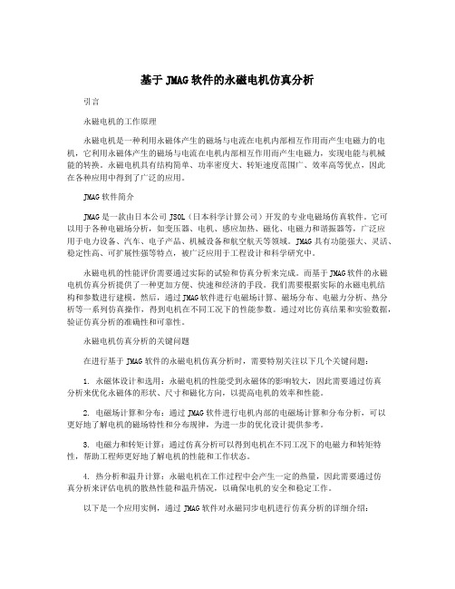
基于JMAG软件的永磁电机仿真分析永磁电机是一种利用永磁体作为励磁源产生磁场的电机。
它具有体积小、重量轻、转速高、效率高等优点,在交通工具、家电、工业自动化等领域得到广泛应用。
为了提高永磁电机的性能和效率,使用JMAG软件进行仿真分析是一个非常有效的方法。
JMAG是一种电磁场仿真软件,可以对电机进行电磁场分析、磁场分布分析、电磁耦合分析等。
以下是基于JMAG软件的永磁电机仿真分析的详细内容。
通过JMAG软件建立永磁电机的几何模型。
可以根据实际电机的尺寸和结构,在JMAG软件中建立电机的三维几何模型。
JMAG软件提供了丰富的建模工具和功能,可以方便地创建电机的转子、定子、绕组等部分,并进行相应的几何操作,以得到准确的电机几何模型。
接下来,设置永磁体的磁性。
在永磁电机中,永磁体是产生磁场的关键部分。
通过JMAG软件可以设置永磁体的材料属性和磁化情况。
可以选择不同种类的永磁体材料,设置其磁化强度和方向,以模拟真实永磁体的磁场特性。
然后,设置绕组的电流和电压。
在永磁电机中,绕组是通过电流和电压来产生磁场和转矩的。
通过JMAG软件可以设置绕组的电流大小和方向,以及绕组的电压情况。
可以根据实际需求,设置不同的电流和电压参数,来进行不同工况下的仿真分析。
进行仿真分析。
在设置好永磁体和绕组的参数后,通过JMAG软件进行仿真分析。
可以对永磁电机的电磁场进行分析,得到电磁场的分布情况、磁场密度、磁力线等相关结果。
可以对转矩、功率、效率等关键性能进行仿真计算和分析,以评估电机的性能和优化设计。
通过JMAG软件进行永磁电机的仿真分析,可以帮助设计工程师更好地了解电机的性能特点,为电机的优化设计提供参考依据。
可以有效减少实际制造和测试中的成本和时间,提高设计过程的效率。
基于JMAG软件的永磁电机仿真分析成为电机设计和优化的重要工具。
基于JMAG软件的永磁电机仿真分析

基于JMAG软件的永磁电机仿真分析
随着现代工业的不断发展,永磁电机已经成为了新能源车辆、家电、机械等领域中普遍采用的关键性设备。
为了满足市场需求,设计出的永磁电机需要具有高效、稳定、低噪音等特点,这就需要在设计过程中进行模拟仿真和优化。
JMAG是一款专业的电机设计仿真软件,能够帮助工程师进行永磁电机的全面仿真分析和优化设计。
本文将针对永磁电机的设计和仿真分析进行介绍。
1. 建立模型
在使用JMAG软件进行永磁电机设计之前,首先需要进入软件建立电机模型。
用户可以根据永磁电机的不同类型和使用环境,选择相应的建模方法和建模方式。
对于拟合更为复杂的电机类型,用户可以使用仿真库中提供的示例电机来建立新的模型,或者直接基于已有的电机模型进行调整和更新。
2. 仿真分析
建立好电机模型后,就可以进行仿真分析了。
JMAG提供了多种不同的仿真分析方法和指标,如磁场分析、电磁学力和扭矩分析、损耗特性分析等。
其中,在永磁电机的设计和优化过程中,最为重要的指标则是磁场和扭矩的分析。
在这方面,JMAG提供了全面的仿真工具和分析器,能够在保证仿真精度的情况下,实现快速模拟分析。
3. 优化设计
进行了模拟仿真分析后,就可以对永磁电机的各项性能指标进行评估和优化。
JMAG软件提供了多种优化方法来满足用户不同的需求,比如磁路参数优化、损耗优化、设计尺寸优化等。
优化设计不仅能够提高永磁电机的工作效率和性能,还可以大幅度减少设备成本和制造成本。
在这一过程中,JMAG的优化工具和分析器能够提供高效准确的分析报告,帮助用户尽快找到最优化的设计方案。
最新JMAGDesigner永磁同步电机3D结构场分析基本操作流程

J M A G D e s i g n e r永磁同步电机3D结构场分析基本操作流程JMAG Designer 永磁同步电机3D结构场分析基本操作流程1.设定软件单位制打开JMAG Designer软件,选择Tools菜单下的Preferences,如下图:会跳出如下图对话框,选择左侧的Units,右侧出现的既是软件目前的单位制,如果和您的模型的单位制有差别,可以电机右侧的Edit按钮修改软件的单位制。
2.建模用户可以在JMAG Designer软件自带的Geometry Editor中建模,也支持多种3D格式的图形直接导入,本例采用直接从外部导入.sat格式3D图形的方式。
选择File菜单下的Open,如下图:或者直接点击下图中所示的快捷键,如下图:会弹出如下图对话框,在文件类型中选择ACIS SAT Files(.sat),选中要导入的图形文件。
图形导入后效果,如下图:在做结构分析时,主要的分析对象是电机的定子铁芯,考虑的是铁心受到的电磁力,所以这里对模型进行了简化,只保留定子铁芯。
在上方菜单栏中点击Save,保存。
如下图:3.前处理做结构分析时,一般分两步:模态分析和频域分析。
模态分析是分析模型本身的固有振动频率,频域分析是分析模型受电磁力后的振动频率,这两个频率将影响到电机的噪声情况。
在左侧树形图中右键点击Solid Model,选择New Study下的Eigenmode Analysis,建立一个模态分析的Study。
如下图:赋材料属性在右侧的Toolbox栏下Materials里是软件的材料库,在做结构场分析时,需要用户自己创建材料,左键点击Create New Material。
如下图:此时会弹出材料编辑对话框,修改名字为steel_structural,点击Machanical Properties,在做结构分析时,需要给出材料的密度、杨氏模量和泊松率。
此例给出的是大概值,并非精确值。
基于JMAG软件的永磁电机仿真分析

基于JMAG软件的永磁电机仿真分析永磁电机是一种以永磁体作为磁场源的电机,具有结构简单、效率高、功率密度大等优点,因此在许多领域得到了广泛的应用。
永磁电机的设计和优化需要经过复杂的仿真分析,以确保其性能和可靠性。
而基于JMAG软件的永磁电机仿真分析可以帮助工程师们快速、准确地评估不同设计参数对电机性能的影响,从而提高设计效率和质量。
一、JMAG软件简介JMAG是一款由日本JSOL Corporation开发的专业电磁场有限元软件,其在磁场仿真领域拥有领先的技术和应用经验。
JMAG软件能够模拟和分析各种电磁场问题,包括永磁电机、变压器、感应电机等领域,其强大的仿真分析能力使得工程师能够深入理解电磁场分布规律,从而优化设计方案。
二、永磁电机仿真分析的重要性在永磁电机的设计和优化过程中,仿真分析是至关重要的环节。
通过仿真分析,工程师可以确定电机的电磁场分布、损耗情况、力矩特性等重要参数,帮助设计人员优化电机结构、提高电机性能和效率。
而基于JMAG软件的永磁电机仿真分析能够提供准确的计算结果,帮助工程师在短时间内做出正确的设计决策。
三、永磁电机仿真分析的内容基于JMAG软件的永磁电机仿真分析通常包括以下几个方面的内容:1. 电磁场分布分析:通过JMAG软件可以模拟电机中的磁场分布,包括气隙磁密分布、永磁体磁场强度、励磁线圈磁场等,从而帮助工程师理解电机的工作原理和性能。
2. 损耗分析:电机的损耗是影响电机性能的重要因素,通过JMAG软件可以模拟电机中的铁损耗、铜损耗等,帮助工程师评估电机的热特性和效率。
3. 力矩特性分析:永磁电机的输出力矩是其性能的重要指标之一,通过仿真分析可以计算电机在不同工况下的输出力矩曲线,帮助工程师优化电机的设计。
4. 瞬态分析:电机在启动、停止、调速等瞬态工况下的性能表现对于应用场景至关重要,通过JMAG软件可以模拟电机在不同工况下的瞬态响应,帮助工程师评估电机的动态特性。
四、基于JMAG软件的永磁电机仿真分析案例以某款永磁电机为例,设计人员需要对其进行仿真分析,以评估不同设计参数对其性能的影响。
JMAGDesigner永磁同步电机3D结构场分析基本操作流程

JMAG Designer 永磁同步电机3D结构场分析基本操作流程1.设定软件单位制打开JMAG Designer软件,选择Tools菜单下的Preferences,如下图:会跳出如下图对话框,选择左侧的Units,右侧出现的既是软件目前的单位制,如果和您的模型的单位制有差别,可以电机右侧的Edit按钮修改软件的单位制。
2.建模用户可以在JMAG Designer软件自带的Geometry Editor中建模,也支持多种3D 格式的图形直接导入,本例采用直接从外部导入.sat格式3D图形的方式。
选择File菜单下的Open,如下图:或者直接点击下图中所示的快捷键,如下图:会弹出如下图对话框,在文件类型中选择ACIS SAT Files(.sat),选中要导入的图形文件。
图形导入后效果,如下图:在做结构分析时,主要的分析对象是电机的定子铁芯,考虑的是铁心受到的电磁力,所以这里对模型进行了简化,只保留定子铁芯。
在上方菜单栏中点击Save,保存。
如下图:3.前处理做结构分析时,一般分两步:模态分析和频域分析。
模态分析是分析模型本身的固有振动频率,频域分析是分析模型受电磁力后的振动频率,这两个频率将影响到电机的噪声情况。
在左侧树形图中右键点击Solid Model,选择New Study下的Eigenmode Analysis,建立一个模态分析的Study。
如下图:赋材料属性在右侧的Toolbox栏下Materials里是软件的材料库,在做结构场分析时,需要用户自己创建材料,左键点击Create New Material。
如下图:此时会弹出材料编辑对话框,修改名字为steel_structural,点击Machanical Properties,在做结构分析时,需要给出材料的密度、杨氏模量和泊松率。
此例给出的是大概值,并非精确值。
在Density下的Constant中填入7850,在Young’s Modelus中填入210000,在Poisson’s Rati中填入0.3,点击OK。
JMAG标准培训教程永磁电机

PPT文档演模板
2020/11/2
JMAG标准培训教程永磁电机
PPT文档演模板
操作步骤
l 模型说明 l 创建几何模型 l 定义材料 l 定义条件 l 定义电路 MAG标准培训教程永磁电机
模型整体介绍
模型:为三相四极24槽的永 磁电机。
PPT文档演模板
JMAG标准培训教程永磁电机
求解设置——步长设置
PPT文档演模板
JMAG标准培训教程永磁电机
求解设置——运行
PPT文档演模板
JMAG标准培训教程永磁电机
求解设置——过程监控
PPT文档演模板
JMAG标准培训教程永磁电机
结果显示
PPT文档演模板
JMAG标准培训教程永磁电机
空载磁力线与磁密云图
可直接导入的格式
PPT文档演模板
JMAG标准培训教程永磁电机
采用Geometry editor
PPT文档演模板
JMAG标准培训教程永磁电机
Geometry editor界面
PPT文档演模板
JMAG标准培训教程永磁电机
Geometry editor——创建region
PPT文档演模板
JMAG标准培训教程永磁电机
求解:基本电磁计算(空载)
PPT文档演模板
JMAG标准培训教程永磁电机
几何模型
模型从外部导入 采用Geometry editor 采用Geometry link功
能 采用Template功能
PPT文档演模板
JMAG标准培训教程永磁电机
外部导入模型
PPT文档演模板
JMAG标准培训教程永磁电机
PPT文档演模板
63-基于JMAG的永磁电机退磁分析
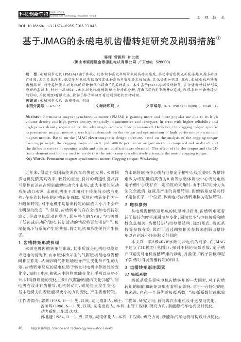
基于JMAG 的永磁的永磁电机电机电机退磁分析退磁分析Demagnetization Analysis of Permanet MagnetMotor Based on JMAG孙明冲 郝双晖 刘吉柱 宋益明(哈尔滨工业大学 机电工程学院,哈尔滨 150001)摘 要:在永磁电机的设计中,经常出现永磁体退磁现象。
永磁体退磁大多数是不可逆的,退磁将直接影响永磁电机的性能。
利用磁路法进行永磁体退磁计算时,无法反映永磁体的实际工作状态。
为此本文对永磁体材料的热稳定性进行计算,并利用JMAG 软件对永磁电机的退磁现象进行了有限元分析,更加准确地反映了永磁的实际工作状态。
关键词关键词::退磁分析;热稳定性;JMAG;有限元分析Abstract: Permanent magnet demagnetization phenomena offten appear in the design of Permanet Magnet Motor . Most of permanent magnet demagnetization is irreversible, and the demagnetization will influence the performance of the permanent magnet motor directly. The actual working condition of permanent magnet unable be reflected when calculating permanent magnet demagnetization by the method of magnetic circuit.So the permanent magnet thermal stability of the Permanent magnet materials was calculated in this paper,and then analyzed permanent magnet motor demagnetization phenomenon by using the JMAG software, the permanent actual working mode was reflected accurately.Key words: Demagnetization analysis;Thermal stability;JMAG;Finite element analysis1 引言与传统电励磁电机相比,永磁电机具有结构简单、运行可靠、体积小、效率高、电机形状和尺寸灵活多样[1]等优点,近年来得到了广泛的应用。
永磁无刷直流电动机及其控制系统的性能计算的开题报告

永磁无刷直流电动机及其控制系统的性能计算的开题报告项目名称:永磁无刷直流电动机及其控制系统的性能计算研究目的:永磁无刷直流电动机是一种高效、低噪音、高可靠性的电机,在汽车、家电、工业控制等领域中应用广泛。
为了更好地控制这种电机的性能,需要进行一系列的计算分析。
本研究旨在建立永磁无刷直流电动机的性能计算模型,并开发相应的控制系统。
研究内容:1. 永磁无刷直流电动机的基本原理与工作原理。
2. 建立永磁无刷直流电动机的数学模型,包括电机的结构参数、电磁特性参数、机械特性参数等。
3. 基于数学模型,计算永磁无刷直流电动机的性能参数,如速度、扭矩、功率、效率等。
4. 设计永磁无刷直流电动机的控制电路,采用模拟控制和数字控制两种方法,并比较不同控制方法的优缺点。
5. 构建永磁无刷直流电动机的控制系统,包括电机驱动器、传感器、控制器等,实现对电机的控制与调节。
研究意义:永磁无刷直流电动机具有广泛的应用前景,如电动汽车、智能家居、工业自动化等领域。
本研究能够建立永磁无刷直流电动机的性能计算模型,并设计相应的控制系统,能够提高电机的效率和可靠性,并且节能降耗。
本研究对于推动产业发展和提高生活质量具有重要的意义。
研究方法:本研究主要采用数值计算方法,利用数学模型对永磁无刷直流电动机进行计算分析。
同时,采用仿真技术模拟电机运行状态、控制参数等,并通过实验验证模型的有效性。
预期结果:该研究预期可以建立永磁无刷直流电动机的性能计算模型及控制系统,并能够通过实验验证模型的有效性。
同时,本研究将探究数值计算及仿真方法在永磁无刷直流电动机控制系统中的应用,为相关领域的研究提供一定参考和借鉴价值。
基于JMAG软件的高速永磁电机的研究与设计

永磁体厚度、绕组节距 以及极弧系数进行了优化仿真。通过 J M A G软件建模仿真 ,完成了对高速 永磁 电机 的磁密、磁感线 、空负载 电动势 以及 电机转矩 的分析 ,该 电磁方案可为高速永磁 电机设计与优化分析提供
一
定的理论依据 。
关键词 :高速永磁 电机 ;J M A 6软件;仿真 中图分类号 :T M 3 5 1 文献标识码 :A 文章编号 :
Re s e a r c h a n d De s i g n o f Hi g h - Spe e d Pe r ma ne nt Ma g ne t
Mo t o r Ba s e d o n J M AG S o f t wa r e
Z HAO L o n g — t a o , Y I N Ya n - j i e , DO U Z h o n g — s e n ( C o l l e g e o fl n f o r ma t i o n a n d El e c t r i c a l E n g i n e e r i n g , S h a n d o n g U n i v e r s i t y o f S c i e n c e a n d T e c h n o l o g y , Qi n g d a o 2 6 6 5 9 0 , C h i n a )
ma ne g t i c ie f l d l i n e s , a i r f o r c e nd a he t mo t o r l o a d t o r q u e . Th e r e s u l t s s h o w t h a t t h e e l e c t r o ma ne g t i c s c h e me c a n p r o v i d e c e r t a i n he t o r e t i c a l b a s i s f o r
2023年永磁无刷直流电动机项目工作报告

永磁无刷直流电动机项目工作报告目录概论 (4)一、永磁无刷直流电动机项目基本情况 (4)(一)、永磁无刷直流电动机项目名称及建设性质 (4)(二)、永磁无刷直流电动机项目承办单位 (5)(三)、战略合作单位 (5)(四)、永磁无刷直流电动机项目提出的理由 (5)(五)、原材料供应 (6)(六)、永磁无刷直流电动机项目能耗分析 (7)(七)、环境保护 (8)(八)、永磁无刷直流电动机项目建设符合性 (9)(九)、永磁无刷直流电动机项目进度规划 (10)(十)、投资估算及经济效益分析 (11)(十一)、报告说明 (12)(十二)、永磁无刷直流电动机项目评价 (14)二、永磁无刷直流电动机项目市场前景分析 (15)(一)、建设地经济发展概况 (15)(二)、行业市场分析 (17)三、建设单位基本信息 (18)(一)、永磁无刷直流电动机项目承办单位基本情况 (18)(二)、公司经济效益分析 (20)四、建设规划 (21)(一)、产品规划 (21)(二)、建设规模 (23)五、危机管理与应急预案 (25)(一)、危机预警与监测 (25)(二)、应急预案与危机响应 (26)(三)、危机沟通与舆情控制 (28)(四)、危机后教训与改进 (30)六、永磁无刷直流电动机项目投资可行性分析 (32)(一)、永磁无刷直流电动机项目估算说明 (32)(二)、永磁无刷直流电动机项目总投资估算 (33)(三)、资金筹措 (34)七、永磁无刷直流电动机项目运营管理 (37)(一)、运营管理机构设置 (37)(二)、运营管理流程 (40)(三)、人员配备及培训 (44)(四)、质量管理体系 (46)(五)、安全生产管理 (48)(六)、环境管理 (50)(七)、设备维护与保养 (52)(八)、应急预案与处置 (54)(九)、绩效评估 (56)八、永磁无刷直流电动机项目实施进度计划 (58)(一)、建设周期 (58)(二)、建设进度 (59)(三)、进度安排注意事项 (61)(四)、人力资源配置 (62)(五)、员工培训 (64)(六)、永磁无刷直流电动机项目实施保障 (65)九、法律与合规性 (67)(一)、相关法律法规概述 (67)(二)、永磁无刷直流电动机项目合同管理 (69)(三)、知识产权保护 (71)(四)、劳动法规与员工权益 (72)(五)、环境保护法规遵循 (74)十、风险管理与应对策略 (75)(一)、风险管理流程 (75)(二)、风险识别与评估 (79)(三)、风险控制与应对策略 (80)(四)、危机管理与应急预案 (82)十一、市场营销策略 (85)(一)、市场定位与目标客户群 (85)(二)、竞争对手分析 (87)(三)、营销策略与推广计划 (89)(四)、产品定价与销售渠道 (90)(五)、售后服务体系 (92)十二、未来发展战略 (94)(一)、未来市场定位与业务拓展 (94)(二)、技术创新与研发方向 (96)(三)、国际化战略与全球市场 (97)(四)、可持续发展战略 (99)十三、永磁无刷直流电动机项目监督与评估 (101)(一)、监督机构及职责 (101)(二)、监测与评估指标体系 (103)(三)、监督与评估周期 (105)(四)、监督与评估报告 (107)概论本永磁无刷直流电动机项目报告按照现代永磁无刷直流电动机项目管理理论及标准流程编写,着重分析了永磁无刷直流电动机项目管理中的系统思维、团队协作、时间成本控制等关键要素,并将理论与实验案例相结合,提出创新性的改进措施。
Jmag精典分析实例-永磁电动机
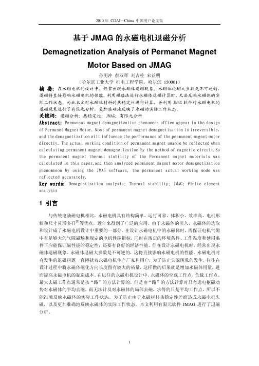
JMAG Application NoteAnalysis of a Permanent Magnet Brush Motor CONTENTSOverview (2)1 Analysis Scope (3)2 Motor Specification (3)3 Analysis Results (6)3.1 Speed-Torque and Torque-Current Curves (6)3.2 Flux Density Distribution (7)4 Analysis Steps (8)5 FEM Model Creation (9)5.1 Mesh Model (9)5.1.1 2D Model (9)5.1.2 Air Region (9)5.1.3 Mesh Generation (9)5.2 Material Properties (10)5.3 Analysis Conditions (10)5.3.1 Analysis Control (10)5.3.2 Step (10)5.3.3 Symmetry Boundary 2D (10)5.3.4 Motion (10)5.3.5 Electromagnetic Force and Torque Calculation (10)5.3.6 Slide (11)5.3.7 FEM Coil (11)5.3.8 Circuit (12)5.4 Summary (12)6 Results Display (13)6.1 Speed-Torque and Torque-Current Curves (13)6.2 Flux Density Distribution (13)Appendix Settings for JMAG Analysis of a Permanent Magnet Brush Motor (14)Appendix 1 Mesh Model Settings (14)Appendix 2 Material Property Settings (16)Appendix 3 Analysis Condition Settings (17)OverviewThe purpose of this Application Note is to help JMAG users understand the steps and settings used to analyze a brush-type PM motor.The model data from the JMAG Application Catalog can be downloaded to view the analysis model, settings and results described in this Application Note.The organization is as follows:Section 1 Analysis ScopePresents the scope of the analysis.Section 2 Motor SpecificationSpecifies the motor used for the analysis, including the motor geometry, the coilarrangement, material properties and the orientation of the magnet.Section 3Analysis ResultsShows the results obtained for the Speed-Torque and Torque-Current curves as wellas saturation.Section 4 Analysis StepsDescribes the analysis steps used to obtain the results presented in Section 3.Section 5 FEM Model CreationDescribes the analysis settings, including the mesh model, the material propertiesand the condition settings.Section 6 Results DisplayDescribes how to display the analysis results, such as creating graphs for the torqueand current, as well as showing contour plots for the flux density distribution.AppendixShows the JMAG mesh model and lists the settings, including material propertiesand analysis conditions. The analysis settings are identical to the settings used inthe model files available from our Website.The JMAG module(s) and the version used for the analysis are:Module DPVersion 8.41 Analysis ScopeA brush motor rotates when the brush and commutator alternate the direction of the current passing through the armature coils. The torque is proportional to the product of the current and torque constant. Thus, a large torque constant is required for the minimum current. However, increasing the torque constant reduces the speed, so it is important to identify the magnetic behavior of the brush motor, including the torque versus current and the torque versus speed. This note presents how the characteristics of the brush-type PM motor can be obtained, including torque versus current (T-I) and torque versus speed (T-N).2 Motor SpecificationThe specification of the permanent magnet brush motor used for this analysis is shown inTable 2.1.Stator coreMagnetRotor core ShaftCoilFigure 2.1 PM Brush MotorTable 2.1 SpecificationNumber of poles 2 Number of slots 3 Power supplyDC 12 V Number of turns 20 turn/slotCoilResistance 0.05 Ω/phaseCoil windingConcentrated winding: see Figure 2.2Number of commutator bars3 Slit width between commutator bars 7.5 degrees Brush width 60 degrees Brush / commutatorContact resistance0.072 ΩStator core (outside dimension) R 19.2 mm × thickness 32 mm Rotor core (outside dimension) R 12.0 mm × thickness 32 mm Magnet (outside dimension)R 17.0 mm × thickness 32 mmGap0.3 mmTable 2.2 Material Magnetic PropertiesPart Property Stator core Isotropic magnetic material: see Figure 2.3 for BH curve Rotor core Isotropic magnetic material: JFE Steel (50JN600) Shaft Isotropic magnetic material: see Figure 2.3 for BH curveMagnetTDK: FB3G: 60.0 Celsius Orientation: see Figure 2.4Coil Non-magnetic materialU-phaseV-phase W-phaseFigure 2.2 Winding Pattern0.00.20.40.60.81.01.21.41.61.82.0020004000600080001000012000Magnetic field, A/mM a g n e t i c f l u x d e n s i t y , TFigure 2.3 BH Curve (stator core and shaft)Figure 2.4 Orientation of the Magnet3 Analysis ResultsThe Torque-Speed curve, the Torque-Current curve and the flux density distribution can be obtained from analysis of the PM brush motor described in Section 2. Refer to Section 6 for displaying these results.3.1 Speed-Torque and Torque-Current CurvesThe Speed-T orque curve is shown in Figure 3.1, and the Torque-Current curve is shown in Figure 3.2. The graphs show the speed decreases with toque and torque is approximately proportional to current. Also, the speed range controllable in this motor can be seen on the Speed-Torque curve.0500010000150002000025000300000.000.050.100.150.200.25Torque, NmR o t a t i o n s p e e d , r p mFigure 3.1 Speed versus Torque0.05.010.015.020.025.030.00.000.050.100.150.200.25Torque, NmC u r r e n t , AFigure 3.2 Torque versus Current3.2 Flux Density DistributionFigure 3.3 shows the flux distribution at the rotation speed of 12000 rpm. The flux density is particularly high in the regions circled in red. The flux from the rotor and the stator are adding together. When the flux of the rotor or stator leaks due to the magnetic saturation and does not interact with the other part, the torque may be reduced.(Unit: T)Figure 3.3 Flux Distributions at 12000 rpm (left: 0.00293 seconds, right: 0.005 seconds)4 Analysis StepsA number of transient response magnetic field analyses are required to obtain the Speed-Torque and Torque-Current curves.The average torque is calculated at several currents, for a range of speeds. Then, spreadsheet software is used to create graphs for the Speed-Torque and Torque-Current curves.The analysis steps are as follows.STEP 1: Create an FEM model by:a. Creating the geometryb. Specifying the materialsc. Specifying the circuit and analysis conditionsSTEP 2: Run the electromagnetic analysis and calculate the average torqueSTEP 3: Repeat STEP 1 at different speedsSTEP 4: Evaluate the results using spreadsheet software5 FEM Model CreationThe FEM model required to run magnetic field analysis is composed of a mesh model, the material properties, and the analysis conditions. The settings required for the calculation of the Speed-Torque and Torque-Current curves are in the Appendix, with some helpful notes included here.5.1 Mesh Model“Appendix 1 Mesh Model Settings” lists of the meshing parameters used for the analysis.Some notes about the creation of the mesh model are provided below.5.1.1 2D ModelThe 2D analysis of JMAG’s DP module is a good starting point for this analysis because it is easier and faster than 3D. 2D analysis can be used when the stack length of the rotor and the stator are the same and the two cores are aligned axially.In this analysis, the magnetic flux in the axial direction, such as fringing at the ends of the stacks, is ignored.5.1.2 Air RegionThe air region is required even if the magnetic circuit is closed within the motor, because of some flux leakage, usually caused by saturation. An adequate size of the air region is 1.05 – 2.5 times the outer radius of the stator core, and the optimum value varies with state of the saturation or other sources of stray flux outside the stator.In this analysis, the mesh model including the air region outside the stator core is set to 1.5 times the radius of the motor.A symmetry boundary condition specifies the outer circumference of the mesh model. See “5.3.3 Symmetry Boundary 2D”.5.1.3 Mesh GenerationSince the rotor has rotational motion, the Cylindrical Slide Mesh option can be used to efficiently generate the mesh in the gap between the stator and the rotor for each increment of motion.The number of divisions is set so there are at least 8 divisions in one period of the torque. Generally, the divisions needed for the accurate calculation vary with motor geometry. For this analysis, one division is set to about 1/10 of a torque period in the circumferential direction. The number of divisions in the radial direction is set to 3, which is the minimum value that can be used for Cylindrical Slide Mesh in the air gap.5.2 Material PropertiesThe material properties of the parts are specified with reference to the specification. See Figure 2.1. The settings are listed in “Appendix 2 Material Property Settings”.5.3 Analysis ConditionsSome notes about the analysis conditions are provided below. The settings are listed in “Appendix 3 Analysis Condition Settings”.5.3.1 Analysis ControlTransient response analysis should be selected when the magnetomotive force and the rotation of the rotor need to include time-varying phenomena such as induced voltages or eddy currents.5.3.2 StepThe rotor is set to rotate one degree per step in this analysis. The time interval is used to specify the speed for each point on the Speed-Torque curve. When the analysis needs to run for a mechanical angle of 360 degrees, the number of steps is set to 361 to include the initial starting position.5.3.3 Symmetry Boundary 2DThe symmetry boundary is set on the outer circumference of the mesh model, assuming all magnetic flux stays inside this outermost boundary.5.3.4 MotionThe motion condition is set on the rotating parts including the shaft, rotor core and armature coil. The center of the rotation is the origin and the rotation axis is Z-axis, so A Point on Rotation Axis is set to (0,0,0) and the Direction of Rotation Axis is set to (X,Y,Z)=(0,0,1).To obtain the Speed-Torque curve, a number of analyses at different speeds will need to be specified.5.3.5 Electromagnetic Force and Torque CalculationFor this analysis, this condition is set on the shaft, rotor core, and the coils to calculate the torque generated in the rotating parts. The Nodal Force method is used when the condition is set on a magnetic material, such as the magnetic steel of the core.5.3.6 SlideThe Cylindrical Slide Mesh option is used to efficiently generate the mesh in the air gap. With this option, the slide condition will be set automatically during the mesh generation. Using this option, the basic mesh of the entire motor stays the same, and for each step of rotation the nodes are simply reconnected along the sliding line in the air gap.5.3.7 FEM CoilAn FEM coil condition needs to be assigned to each phase.The directions of the current flow in the coils are indicated in Figure 5.1.U-phaseW-phaseV-phase : Upward : Downward Figure 5.1 Current Flow Direction Set by the FEM Coil Conditions5.3.8 CircuitThe settings for the supply voltage, the brush and commutator component, and the FEM coil components will specify typical operation of a PM brush DC motor. For this analysis, the voltage is set to a constant 12 V, the number of commutator bars to 3, the slit width between the commutator bars to 7.5 degrees, the brush width to 60 degrees, the contact resistance to 0.072 ohm, the number of coil turns to 20, and the resistance to 0.05 ohm, all shown in the specification, Table 2.1.In JMAG, one FEM coil condition in the FEM model corresponds to one FEM coil component in the circuit. The conditions defined in the circuit are run simultaneously with magnetic field analysis.U-phase W-phaseV-phaseBrush and commutatorsFigure 5.2 Circuit Diagram5.4 SummaryAt this point, the model is complete: the geometry has been entered, the materials have been specified, and the analysis conditions have been set. Next, the analysis is run once for each data point of the Speed-Torque curve.6 Results DisplayAfter the analysis is complete, a PLOT file is created, which is opened in a new window with one click. Many parameters can be displayed, each with choices such as line plots or color contours. The display of the Speed-Torque curve and Torque-Speed curve is described below.6.1 Speed-Torque and Torque-Current CurvesThe graphs for the Speed-Torque and Torque-Current curves are created by exporting the data to the spreadsheet software.To display the Speed-Torque curve graph, open each PLOT file for the different speeds, and select Results > Torque(Electromagnetic Force)> Table > Range:All > Export File to export the torque of each analysis. Calculate the average torque in the spreadsheet by averaging one period of the torque in the steady state. Display the Speed-Torque curve graph is shown in Figure 3.1 by setting the average torque on the horizontal axis, and the speed on the vertical axis.To display the Torque-Current curve graph, open each PLOT file for different rotation speeds, and select Results > Current of FEM Coil > Table > Range:All > Export File to export the current in the FEM coil in each analysis step. Calculate the current in the steady state from the current exported into the spreadsheet file. Display the Torque-Current curve graph shown in Figure 3.2 by setting the average torque on the vertical axis, and the current on the horizontal axis.6.2 Flux Density DistributionInside JMAG, the magnetic field analysis results are in the PLOT file. A contour plot can be used to display the flux density distribution.To display the flux density distribution as shown in Figure 3.3, open the PLOT file, and select Results > Magnetic Flux Density > Contour > Magnetic Flux Density.Appendix Settings for JMAG Analysis of a Permanent Magnet Brush MotorThe mesh model and the settings including the material properties and the analysis conditions are shown in the following sections. The settings are the identical to the model data ” JAC003BM-1200rpm-01e.jcf”, which can be downloaded from “Analysis of a Permanent Magnet Brush Motor” in online JMAG Application Catalog.Appendix 1 Mesh Model SettingsThe mesh model used for the analysis is shown in Figure A.1. The settings for the mesh generation are listed in Table A.1. The basis for the settings is in “5.1 Mesh Model”.Figure A.1 Mesh Model (number of elements: 12,823)(left: including air region, right: excluding air region)Table A.1 Automatic Mesh GenerationParameter ValueMesh Type Cylindrical Slide MeshType of Input Data Region Number of Division along Radial Direction 3 Number of Division along Circumferential Direction 360 Cylindrical Slide MeshScale of Air Region in Vertical Direction1 Generate Mesh While Running Analysis Off Scale of Air Region1.5 Stator core region (mm) 0.5 Magnet region (mm)0.5 Magnet region (around the gap) (mm) 0.4 Shaft region (mm) 1.2 Rotor core region (mm)1.2 Rotor core region (around the gap) (mm) 0.4 Part Element SizeCoil region (mm)1.2 Element Size of Air Region (mm)2.0Appendix 2 Material Property SettingsThe material properties used in the model are listed in Table A.2. The basis for the settings isin “5.2 Material Properties”.Table A.2 Material PropertiesPart Parameter Value Type Isotropic Magnetic MaterialType Nonlinear Material (B-H) Stator core MagnetizingProperties Point Sequence See Figure 2.3Type MagnetType TDK (Material Database)MagnetizingProperties Point Sequence FB3G: 60.0 (Celsius)Type Parallel Pattern (Circular Direction)Number of Poles 2Starting Position theta 0 (deg) 90MagnetMagnetizationDirectionReverseDirectionOnType Isotropic Magnetic MaterialType Nonlinear Material (B-H) Shaft MagnetizingProperties Point Sequence See Figure 2.3Type Isotropic Magnetic MaterialType JFE Steel (Material Database) Rotor core MagnetizingProperties Point Sequence 50JN600Coil Type CoilAppendix 3 Analysis Condition SettingsThe settings used for the analysis conditions and the circuit conditions are listed in Table A.3, Table A.4 and Table A.5. The basis for the settings is in “5.3 Analysis Conditions”. The conditions with the ◆ symbol specify the motor geometry, and there is no need to change them when modifying the analysis settings. The conditions without ◆ can be modified freely.Table A.3 Analysis ConditionsCondition ParameterValueType2D Transient Response Analysis Analysis Control ◆ (see 5.3.1) Stack Length(m) 0.032 Number of Steps 361 Step Regular IntervalInitial Value (sec) 0End Point (sec)1.388×10⁻⁴(Varies with specified speed)・2400rpm :6.944×10⁻⁵・3600rpm :4.629×10⁻⁵・6000rpm :2.777×10⁻⁵・12000rpm :1.388×10⁻⁵・24000rpm :6.944×10⁻⁶Step(see 5.3.2)Regular IntervalNumber ofDivision1Symmetry Boundary 2D ◆ (see 5.3.3) Target Outer circumferenceof mesh model Target Rotor core, Coil, Shaft Type RotationA Point on Rotation X,Y ,Zcoordinate (m) (0,0,0) Direction of Rotation AxisVX,VY ,VZ(0,0,1)Definition Displacement Parameter Velocity Motion (see 5.3.4)Method Constant :1200rpm(Rotation speed is specified)Table A.4 Analysis ConditionsCondition ParameterValueTarget Rotor core, Coil, Shaft A Point on Torque Axis X,Y ,Zcoordinate (m) (0,0,0) Torque Axis VectorX,Y ,Z(0,0,1)Electromagnetic Force and Torque Calculation (see 5.3.5)Method Nodal ForceRegion Edge 1 Gap edge on rotor side Slide ◆ (see 5.3.6) TargetRegion Edge 2Gap edge on stator side Region CoilsFEM Coil ◆ (see 5.3.7)Direction (2D)See Figure 5.1Table A.5 Circuit Conditions (see 5.3.8)Condition Parameter Value Voltage (V) Constant Supply Voltage Constant (V) 12 FEM Coil IDCoils Number of Turns (turn) 20 FEM coil PropertiesResistance (Ω) 0.05Number of Brushes2 Number of Commutator bars3 Slit Width betweenCommutator bars (SlidWid) (deg) 7.6Brush Width (deg) 60 Initial Position (deg) 0 Brush/CommutatorContact Resistance of Brush and Commutator (Ω)0.072URL http://www.jri.co.jp/pro-eng/jmag/support/e/catalog/Technical SupportJRI Solutions, Ltd.Engineering Technology DivisionJMAG Support Teamjmag-support@sci.jri-sol.co.jporDistributor in your countryJMAG Application Note Copyright(C) 2006 JRI Solutions, Ltd. All Rights Reserved.。
基于JMAG软件的永磁电机仿真分析

基于JMAG软件的永磁电机仿真分析【摘要】JMAG是一款功能齐全、应用广泛的电磁场分析软件,可以对不同领域的不同电机、电磁设备进行精确的电磁场分析,这里主要介绍JMAG软件对永磁电机的结构分析,并对其进行仿真校核,根据电机的振动、噪音等情况进行解析,电机仿真分析是电机设计与设计优化可靠的依据及基础。
【关键词】JMAG软件;电机仿真近年来,钕铁硼永磁材料性能不断提高,价格随着性能提高确反而有所下降,永磁电机普遍运用于国防、医疗、家用电器、新能源汽车等领域,而其永磁材料绝大部分是钕铁硼,目前永磁电机往大功率化、轻量化、高速化、集成化等方向发展,是非常具有发展潜能的一种高功能设备,较于传统电机它兼具的优势是多方面的,比如①由磁钢直接产生气隙磁密,结构在一定程度上简化,运行更可靠、稳定;②转子损耗更低,电机可以达到尽量宽的高效率区间;③调速范围宽;④转动惯量小;⑤电机体积更小,具有更高的功率密度及转矩密度。
一、JMAG软件JMAG软件来自日本总研(JRI)开发的一款电磁场分析软件且其功能非常齐全,在各国对其运用非常广泛。
(一)JMAG软件优势1.操作界面非常人性化JMAG将前后处理和运算界面联结一块,在操作上变得更加方便、简单、易把握,用户在短时间内就可以进行电机基本性能的模拟培训,这样可以节省很多时间与人力资源;2.网格剖分方便JMAG软件可以根据用户的实质需求情况进而提供不同的网格剖分,得到高精度剖分;3.应用范围广JMAG软件可以对不同领域的不同电机、电磁设备进行精确的电磁场分析,为用户提供电机设计及设计优化帮助,缩短研发周期;4.建模快捷方便,材料库齐全,模型精确高无论任何复杂情况,JAMG能精确的创建与电磁场有相关的复杂模型,它具有巨大的各种不同材料数据库以及拥有一套完善的各类划分工具,JMAG软件还可以引入许多其它软件比如CAD、Solidworks、Pro/E、UG、CATIA等的模型。
保证产品在进行分析时得到准确结果,那么完整以及精细的电机模型是相当重要的,模型的精确性如果越高,那么所得的结果包含在模型尺寸以及属性上的轻微差异的可能性就会越高;5.求解器众多,快捷方便JMAG软件具备各类电磁、温度以及仿真等众多的求解器,可以快捷、精确得出电磁场分析结果。
JMAG计算永磁直流电动机报告
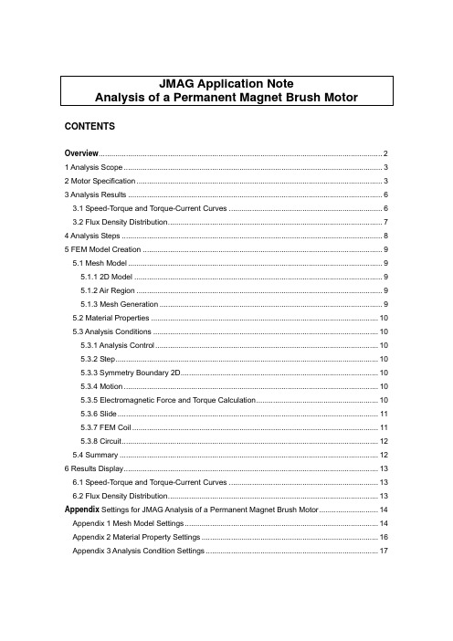
使用JMAG计算永磁直流电动机报告本报告共分为4个部分一计算某一转速下的电机性能二计算电机的起动性能三计算某一负载下的电机性能四求堵转情况下的电机性能下面分别对此进行介绍一转速为8571rpm时的电机性能电机模型电机模型电路双击绕组,即可看见叠绕组磁通密度分布图磁力线分布图电密分布图电磁转矩曲线转矩平均值为0.02784N.m电流曲线图电流平均值为2.941A绕组功率曲线图绕组功率平均值为29.34W绕组铜耗曲线图绕组铜耗平均值为4.03W则电磁功率=绕组功率-绕组铜耗=25.31W换向器上每个挂钩相对于大地的电压任意两个换向器片之间的电压铁损曲线图铁损为1.3W在上述数据的基础上,根据电机公式即可得到电机的其它参数电刷压降=电流*电刷和换向器之间的接触电阻*2=2.941*0.2V*2=1.1764V 电刷与换向器的接触电损耗=电流*电刷压降=3.46W假设总机械损耗和风摩损耗为1.2W。
输入功率=电流*电压=2.941*12=35.292W总损耗=机械损耗+电刷与换向器的接触电损耗+铜耗+铁损=10W输出功率=电磁功率-铁耗-机械损耗=25.31-1.2-1.3=22.81W效率=输出功率/输入功率*100%=64.4%二计算电机的起动性能起动过程转速为11294rpm起动电流起动电流平均值为0.16A三计算某一负载下的电机性能在计算某一负载下的电机性能时,我首先是直接加的负载转矩,得到一个曲线,在此基础上,我又加了电磁转矩算出一条曲线(0.0282)。
这里只给出加电磁转矩的曲线转速曲线图得到转速为8572rpm电流曲线图得到电流值为2.915A四求堵转情况下的电机性能堵转转矩堵转转矩为0.127N.m堵转电流堵转电流为12.84A对于堵转情况,这里只是求电磁堵转,并没有考虑机械摩擦转矩。
因此所算得的值要小于实际测得的值。
基于JMAG软件的永磁电机仿真分析

基于JMAG软件的永磁电机仿真分析【摘要】本文介绍了基于JMAG软件的永磁电机仿真分析。
在分别说明了本研究的背景、目的和意义。
在将JMAG软件进行了介绍,分析了永磁电机的结构和电磁场特性,探讨了永磁电机的性能仿真和优化设计。
在总结了JMAG软件在永磁电机仿真分析中的应用价值,探讨了未来的发展方向。
本文为研究永磁电机提供了重要的理论支持和技术指导,为永磁电机的设计与优化提供了有力的工具和方法。
JMAG软件的运用使得永磁电机的仿真分析更加准确、高效。
未来可进一步拓展研究方向,不断提高永磁电机的性能和效率。
JMAG软件的应用将在永磁电机领域具有广阔的发展前景。
【关键词】永磁电机、JMAG软件、仿真分析、结构分析、电磁场分析、性能仿真、优化设计、应用价值、未来发展、总结。
1. 引言1.1 研究背景为了更好地了解永磁电机的性能特点和工作原理,研究人员开始使用JMAG软件进行仿真分析。
JMAG软件是一款专业的电磁场仿真软件,通过该软件可以对永磁电机的结构、电磁场进行详细的分析,从而帮助工程师更好地设计和优化永磁电机。
在现实工程中,永磁电机的设计与优化需要耗费大量的时间和资源。
通过使用JMAG软件,可以大大节省设计和开发成本,提高工作效率,同时保证永磁电机的性能和可靠性。
本文将重点介绍基于JMAG软件的永磁电机仿真分析,旨在探讨如何通过该软件对永磁电机进行优化设计,提高其性能和效率。
1.2 研究目的研究目的:本研究旨在通过基于JMAG软件的永磁电机仿真分析,探究永磁电机在不同工况下的性能表现及优化设计方法,从而提高永磁电机的工作效率和性能稳定性。
具体目的包括:1.通过对永磁电机结构的分析,深入了解不同部件之间的相互作用及其对永磁电机性能的影响;2.利用JMAG软件进行电磁场分析,研究永磁电机在不同激磁条件下的电磁特性,以实现更准确的效率预测;3.通过性能仿真,评估永磁电机在不同工况下的性能指标,为实际应用提供参考和指导;4.利用优化设计方法,通过JMAG软件对永磁电机进行优化,提高其效率和性能表现,实现节能环保的目的。
基于JMAG软件的永磁电机仿真分析
基于JMAG软件的永磁电机仿真分析引言永磁电机的工作原理永磁电机是一种利用永磁体产生的磁场与电流在电机内部相互作用而产生电磁力的电机,它利用永磁体产生的磁场与电流在电机内部相互作用而产生电磁力,实现电能与机械能的转换。
永磁电机具有结构简单、功率密度大、转矩速度范围广、效率高等优点,因此在各种应用中得到了广泛的应用。
JMAG软件简介JMAG是一款由日本公司JSOL(日本科学计算公司)开发的专业电磁场仿真软件。
它可以用于各种电磁场分析,如变压器、电机、感应加热、磁化、电磁力和谐振器等,广泛应用于电力设备、汽车、电子产品、机械设备和航空航天等领域。
JMAG具有功能强大、灵活、稳定性高、可扩展性强等特点,被广泛应用于工程设计和科学研究中。
永磁电机的性能评价需要通过实际的试验和仿真分析来完成。
而基于JMAG软件的永磁电机仿真分析提供了一种更加方便、快速和经济的手段。
我们需要根据实际的永磁电机结构和参数进行建模。
然后,通过JMAG软件进行电磁场计算、磁场分布、电磁力分析、热分析等一系列仿真操作,得到电机在不同工况下的性能参数。
通过对比仿真结果和实验数据,验证仿真分析的准确性和可靠性。
永磁电机仿真分析的关键问题在进行基于JMAG软件的永磁电机仿真分析时,需要特别关注以下几个关键问题:1. 永磁体设计和选用:永磁电机的性能受到永磁体的影响较大,因此需要通过仿真分析来优化永磁体的形状、尺寸和磁化方向,以提高电机的效率和性能。
2. 电磁场计算和分布:通过JMAG软件进行电机内部的电磁场计算和分布分析,可以更好地了解电机的磁场特性和分布规律,为进一步的优化设计提供参考。
3. 电磁力和转矩计算:通过仿真分析可以得到电机在不同工况下的电磁力和转矩特性,帮助工程师更好地了解电机的性能和工作状态。
4. 热分析和温升计算:永磁电机在工作过程中会产生一定的热量,因此需要通过仿真分析来评估电机的散热性能和温升情况,以确保电机的安全和稳定工作。
基于JMAG软件的永磁电机仿真分析

基于JMAG软件的永磁电机仿真分析
永磁电机是一种具有优异性能的电机,近年来得到了广泛的应用。
为了更好地设计和
优化永磁电机,仿真分析技术被广泛应用。
JMAG是一款专业的电磁场仿真软件,可用于永磁电机的仿真与分析。
本文将对基于JMAG软件的永磁电机仿真分析进行介绍。
首先,设计永磁电机的模型。
JMAG软件提供了丰富的永磁电机模型,使得电机设计变得更加简单。
用户可以根据实际需要选择相应的模型或者自行设计新的模型。
在设计模型时,需要定义永磁体的材料参数、线圈参数等,同时也可以定义电机的外部条件,如电源
电压、负载情况等。
其次,进行永磁电机的电磁场分析。
在完成模型的设计后,可以进行电机的电磁场分析。
JMAG软件采用快速有限元方法(FEM)进行电磁场模拟,能够实现对电机的三维电磁场、磁场分布、磁通密度、电势、电感等参数的计算和分析。
通过电磁场分析,可以获得永磁
电机的电磁特性和性能参数,如电磁转矩、输出功率、效率等等。
最后,进行永磁电机的性能分析。
在得到了永磁电机的电磁特性和性能参数后,可以
进行性能分析。
JMAG软件提供了丰富的分析功能,如功率谱分析、失效分析等,可以帮助用户全面分析电机的性能,并基于分析结果进行优化设计,以达到更好的性能指标。
基于JMAG软件的永磁电机仿真分析

基于JMAG软件的永磁电机仿真分析永磁电机是一种利用永磁体产生磁场来驱动旋转的电机,其在电动汽车、风力发电等领域具有重要应用。
为了更好地理解和优化永磁电机的性能,仿真分析成为了一种有效的工具。
JMAG软件是一款专业的电磁场仿真软件,提供了强大的功能和精确的仿真结果,因此被广泛用于永磁电机的仿真分析。
永磁电机的性能和效率受多种因素影响,包括永磁体的材料和形状、电机的结构和线圈布局等。
针对这些因素,利用JMAG软件进行仿真分析可以帮助工程师更好地理解电机的工作原理和特性,从而优化设计方案。
本文将详细介绍基于JMAG软件的永磁电机仿真分析的方法和步骤,并结合实际案例进行分析和讨论。
进行永磁电机的建模是仿真分析的第一步。
在JMAG软件中,可以通过建立几何模型、定义材料参数和设置边界条件来完成电机的建模。
对于永磁电机而言,永磁体的建模尤为重要,因为永磁体的性能直接影响电机的输出功率和效率。
在建模过程中,还需要考虑电机的结构和线圈布局,以及空气隙和铁心等部件的影响。
一旦完成电机的建模,接下来就是进行电磁场分析。
JMAG软件可以通过有限元方法求解电机内部的磁场分布,包括磁感应强度、磁场密度和磁力线等参数。
通过分析这些参数,可以了解电机内部的磁场分布情况,检查是否存在磁场偏斜、磁场饱和等问题,为进一步优化电机提供参考。
还可以利用JMAG软件进行电机的磁路分析和电磁场热耦合分析。
磁路分析可以评估电机的磁路长度、磁阻和漏磁情况,以及磁路中可能存在的损耗和磁滞等问题。
电磁场热耦合分析则能够评估电机在工作时的温升情况,找出可能存在的热点和温度过高的部位,为电机的散热设计提供依据。
JMAG软件还提供了丰富的后处理功能,可以对仿真结果进行可视化和分析。
可以绘制磁场分布图、磁通密度图、电磁力分布图等,直观地了解电机内部的磁场分布情况。
还可以通过后处理功能进行参数化分析,评估不同设计方案对电机性能的影响,为优化设计方案提供依据。
- 1、下载文档前请自行甄别文档内容的完整性,平台不提供额外的编辑、内容补充、找答案等附加服务。
- 2、"仅部分预览"的文档,不可在线预览部分如存在完整性等问题,可反馈申请退款(可完整预览的文档不适用该条件!)。
- 3、如文档侵犯您的权益,请联系客服反馈,我们会尽快为您处理(人工客服工作时间:9:00-18:30)。
使用JMAG计算永磁直流电动机报告
本报告共分为4个部分
一计算某一转速下的电机性能
二计算电机的起动性能
三计算某一负载下的电机性能
四求堵转情况下的电机性能
下面分别对此进行介绍
一转速为8571rpm时的电机性能
电机模型
电机模型电路双击绕组,即可看见叠绕组
磁通密度分布图
磁力线分布图
电密分布图
电磁转矩曲线转矩平均值为0.02784N.m
电流曲线图
电流平均值为2.941A
绕组功率曲线图绕组功率平均值为29.34W
绕组铜耗曲线图
绕组铜耗平均值为4.03W
则电磁功率=绕组功率-绕组铜耗=25.31W
换向器上每个挂钩相对于大地的电压
任意两个换向器片之间的电压
铁损曲线图
铁损为1.3W
在上述数据的基础上,根据电机公式即可得到电机的其它参数
电刷压降=电流*电刷和换向器之间的接触电阻*2=2.941*0.2V*2=1.1764V 电刷与换向器的接触电损耗=电流*电刷压降=3.46W
假设总机械损耗和风摩损耗为1.2W。
输入功率=电流*电压=2.941*12=35.292W
总损耗=机械损耗+电刷与换向器的接触电损耗+铜耗+铁损=10W
输出功率=电磁功率-铁耗-机械损耗=25.31-1.2-1.3=22.81W
效率=输出功率/输入功率*100%=64.4%
二计算电机的起动性能
起动过程
转速为11294rpm
起动电流起动电流平均值为0.16A
三计算某一负载下的电机性能
在计算某一负载下的电机性能时,我首先是直接加的负载转矩,得到一个曲线,在此基础上,我又加了电磁转矩算出一条曲线(0.0282)。
这里只给出加电磁转矩的曲线
转速曲线图
得到转速为8572rpm
电流曲线图
得到电流值为2.915A
四求堵转情况下的电机性能
堵转转矩
堵转转矩为0.127N.m
堵转电流
堵转电流为12.84A
对于堵转情况,这里只是求电磁堵转,并没有考虑机械摩擦转矩。
因此所算得的值要小于实际测得的值。