苍南双华电机保护器JDB-YE+使用手册
爱达顿电闸器与保护电缆门辅助电机控制装置说明说明书
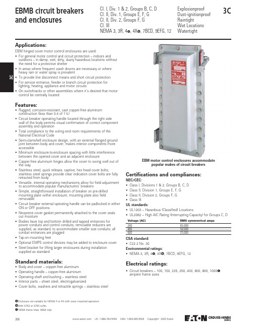
3EBM motor control enclosures accommodatepopular makes of circuit breakersApplications:EBM hinged cover motor control enclosures are used:• For general motor control and circuit protection – indoors and outdoors – in damp, wet, dirty, dusty hazardous locations without the need for a protective shelter• In areas where frequent wash downs are necessary or where heavy rain or water spray is prevalent• To provide line disconnect means and short circuit protection • For service entrance, feeder or branch circuit protection for lighting, heating, appliance and motor circuits• On switchracks or other assemblies where it’s desired that motor control be centrally locatedFeatures:• Rugged, corrosion-resistant, cast copper-free aluminum construction (less than 0.4 of 1%)• Circuit breaker operating handle located through the right side wall of the body permits visual confirmation of correct component assembly and operation• Total compliance to the wiring end room requirements of the National Electrical Code• Semi-clamshell enclosure design, with an external flanged ground joint between body and cover, makes interior components more accessible• Minimum enclosure-to-enclosure spacing with little interference between the opened cover and an adjacent enclosure• Copper-free aluminum hinges allow the cover to swing well out of the way• Stainless steel, quick release, captive, hex head cover bolts;stainless steel springs provide clear indication cover bolts are fully retracted from body• Versatile, internal operating mechanisms allow for field adjustment to accommodate popular manufacturers’ breakers• Simple, straightforward installation of breaker on pre-drilled mounting plate within enclosure; mounting plate also field removable• Circuit breaker external operating handle can be padlocked in either ON or OFF positions• Neoprene cover gasket permanently attached to the cover seals out moisture• Bodies have top and bottom drilled and tapped entrances for power conduits and control conduits; removable reducers are supplied, as standard, to accommodate smaller size conduits; all conduit entrances are plugged • Tap-on mounting feet• Optional EMPS control devices may be added to enclosure cover • Steel bracket for lifting larger enclosures during installation supplied as standardStandard materials:• Body and cover – copper-free aluminum • Operating handle – copper-free aluminum • Operating shaft and bushing – stainless steel • Interior parts – sheet steel, electrogalvanized• Cover bolts, washers and retractile springs – stainless steelElectrical ratings:• Circuit breakers – 100, 150, 225, 250, 400, 600, 800, 1000C ampere frame sizesCertifications and compliances:NEC/CEC:• Class I, Divisions 1 & 2, Groups B, C, D • Class II, Division 1, Groups E, F, G • Class II, Division 2, Groups F, G • Class IIIUL standards:• UL1203 – Hazardous (Classified) Locations• UL2062 – High AIC Rating (Interrupting Capacity) for Groups C, DCSA standard:• C22.2 No. 30Environmental ratings:• NEMA 3, 3R, 4A , 4X B , 7BCD, 9EFG, 12A Enclosure not suitable for NEMA 4 or 4X with cover mounted operators.B With S752 or S753 suffix.C 1000A frame (max. 800A trip).Voltage (AC)RMS symmetrical amps24065,00060025,000D Enclosure not suitable for NEMA 4 or 4X with cover mounted operators.E With S752 or S753 suffix.F If desired, markings on indicating plates may be added to catalog number. Select from the list of standard markings and DSL legend plate listings in Section 1C.G 1000A frame (max. 800A trip).Options:The following options are available from the factory by adding suffix to catalog number – suffixes are added alphanumerically.Part number example:EBMBB-①-WT30FDB36-②①Options in this position are additions to the enclosure itself and should be listed alphanumerically.②Options in this position are modifications to the circuit breaker and should be listed alphanumerically.Suffix • Ambient compensated circuit breaker trip setting .........② AC • Pilot light, 120 VAC, red jewel, with blank indicating plate ................................................................................① J1F • Pilot light, 120 VAC, green jewel, with blank indicating plate ................................................................................① J3F • LED pilot lights (in place of standard incandescent lamps) .............................................................................① LED • START-STOP pushbuttons (requires two spaces) ..........① PB23FD • Space heater, 120V, 25 watts ........................................① R11• Space heater, 240V, 25 watts ........................................① R22• Space heater, 480V, 25 watts ........................................① R44• Insulated neutral with two connectors ...........................① S146• Standard drain (Class I, Groups B, C, D; Class II, Groups E, F, G; Class III) ..................................① S756D • Standard breather and drain (Class I, Groups B, C, D; Class II, Groups E, F, G; Class III) ..................................① S756V D • External epoxy finish ......................................................① S752• Internal and external epoxy finish ...................................① S753• 12-point terminal block – 30 amp, 300V .........................① S786• General purpose control relay, 4-pole N.O., contacts rated 10A at 600V, coil 120 VAC, 50/60 Hz ....................① S787Auxiliary switch on circuit breaker:• 1A and 1B contacts ........................................................② S784• 2A and 2B contacts ........................................................② S785DescriptionPositionin Cat. #EBMB circuit breaker enclosures are available with breakersfrom 100 to 1000G amp frame sizes3H Enclosure not suitable for NEMA 4 or 4X with cover mounted operators.I With S752 or S753 suffix.J Depending on availability from the circuit breaker manufacturer, 1- and 2-pole can be furnished. Information available upon request. Example of an adjusted part number: EBMBBWT100EDH34 becomes EBMBB WT100EDH24.K EBMBA will accept 15 through 70A trip; EBMBB will accept 15 through 100A trip.L EBMBA will accept 10 through 70A trip; EBMBB will accept 10 through 150A trip.M General Electric TEB frame available from 10 through 100A trip. TED frame available from 10 through 150A trip.N Cutler-Hammer FDB and HFD frame available from 15 through 150A trip.O Cutler-Hammer JD and JDB types are 250A frame, available 70, 90, 100 and 125 through 250A trip.P Cutler-Hammer KD and KDB frames available from 100 through 400A trip.Q Cutler-Hammer LD and HLD frame available from 300 through 400 and 500, 600A trip.R Cutler-Hammer MDL frame available from 400 and 500 through 800A trip.S Cutler-Hammer HFD and HJD are rated at 65kAIC at 480V and 25kAIC at 600V.T Interchangeable trip unit.U Non-interchangeable trip unit.V Cutler-Hammer HKD and HLD are rated at 65kAIC at 480V and 35kAIC at 600V.Ordering information:To order an enclosure complete with circuit breaker, insert the manufacturer’s symbols in the designated positions of the catalog number. Symbols are shown in the footnotes below.Enclosures only can be ordered. Select from listings below.Circuit breakerEnclosureNo. of poles JVoltageCircuit breaker frame sizeCat. # Withoutcircuit breaker Circuit breaker amperageCat. # With circuit breaker 3240 VAC or 125-250 VDC 100A K 15-70A EBMBA TT ②TEB32①Circuit breakers ManufacturerSymbolCutler-Hammer WT ②Select trip setting Frame sizeTrip setting100A frame (EHD)K15, 20, 25, 30, 35, 40, 45, 50, 60, 70, 80, 90, 100③Select circuit breaker frame type based on frame size, voltage and manufacturer desired100A and 150A frame250A frame O 400A frame 600A frame 800A frame Manufacturer240 VAC480 VAC600 VAC600 VAC600 VAC600 VAC600 VACCutler-Hammer –EHD FDB HFD S JD T JDB U KD T KDB U LD HLD VMDL3CW Enclosure not suitable for NEMA 4 or 4X with cover mounted operators. Breather and drain entries must be plugged for NEMA 4 rating.X With S752 or S753 suffix.Y Dimensions are approximate, not for construction purposes.Z Use /” diameter bolts for mounting all enclosures (see 'H'). Note: Lifting bracket will accommodate a maximum 2 ton hook.A 1” drilled and tapped conduit entry for control conductors supplied with PLG plug (top and bottom).B Conduit entrance(s) for power conductors (top and bottom). All conduit entrance(s) supplied with RE reducer and PLG plug.C 1000A frame (max. 800A trip).Dimensions Y (in inches):ABJ B(conduit entry trade size)Cat. # Enclosure onlyEnclosure size symbolA B C D E F G Drilled and tappedWith REK L M N O P100A frameEBMBA A 18.2517.2519.40 6.0013.0314.7810.252” 1.5” 3.25 3.1310.25––14.50100 and 150A frameEBMBB B 25.7524.7526.90 6.0013.0314.7810.252” 1.5” 3.25 3.1310.25––22.00225 and 250A frameEBMBGG 37.5036.5039.28 6.0013.0314.7810.253” 2.5” 3.25 3.1310.25––34.06400A frameEBMBK K 43.1241.5042.6512.0017.6520.2810.92(2) 3”(2) 2.5” 3.25 3.0010.92––29.23600, 800 and 1000A frame CEBMBLL53.2551.5053.2812.0017.9020.5813.03(2) 4”(2) 3.5”4.003.5013.1341.5018.4029.88ZABB。
JDB-2K智能保护器说明书

电动机智能监控保护装置使用说明整体式分体式、概述JDB-2K电动机智能型电动机保护器,是一种提高电机运行安全和自动化管理水平的智能化仪器,核心采用美国MICROCHIP公司的微机控制器配低功耗集成电路开发而成的。
该保护器具有保护功能齐全,测量参数直观,反应灵敏,动作及时可靠,可以与上位机通讯构成远程监控于一体的高新技术产品。
广泛应用于石油、化工、煤炭、冶金、电力、钢铁、水泥、矿山、轻工、纺织等行业低压电动机保护及远程监控理想的产品。
二、特点1、采用微机技术和高性能低功耗电路,运算高速,性能稳定。
2、整机模块化结构,卡式电流传感器,体积小,安装方便。
也可分体安装,主体外形尺寸按照国际仪表装置标准。
3、采用数字处理技术,测量精度高,线性度好,对故障判断速度快,精确可靠。
4、高清晰宽温带背光LED显示,设置参数与测量及故障记录直观方便。
5、可以与计算机通讯构成远程监控于一体的电机保护网络。
6、一机多用,可取代电流表,电流变送器,热继电器,漏电继电器,电压表。
三、适用范围及使用条件1、380V AC,660V AC三相异步电动机,馈线电路保护。
2、保护器供电电压;220V AC,380V AC、50HZ。
3、外型结构:整体与分体两种形式,分体安装距离≤5米。
4、环境温度:-30℃~+65℃,相对湿度≤90%。
5、使用环境:无足以腐蚀金属和破坏绝缘性能气体的环境。
6、安装在无剧烈震动冲击,强磁场干扰场所和雨雪侵袭的地方。
四、主要功能1、设定功能:额定电流、保护电流曲线、启动时间、三相不平衡、堵转倍数、漏电电流值、通讯地址等。
2、保护功能:过流、堵转、三相不平衡、短路、漏电、断相。
3、显示功能:运行状态、三相电流、漏电值、故障信息等。
4、远传功能:具有4-20mA标准电流输出信号,20mA对应设定的2倍的额定电流值。
5、通讯功能:通过RS485串行通讯与计算机可构成256台保护器常规保护控制网络。
远程数据设定及显示报警,远程电动机启动,停止控制等。
电源保护SB系列双窄型4000A低压电路保护器说明说明书
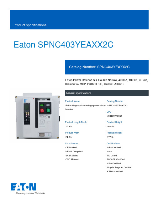
Eaton SPNC403YEAXX2CEaton Power Defense SB, Double Narrow, 4000 A, 100 kA, 3-Pole,Drawout w/ MR2, PXR20LSIG, C403YEAXX2CGeneral specificationsEaton Magnum low voltage power circuitbreakerSPNC403YEAXX2C78668974882116.3 in16.8 in24.9 in177 lbCE Marked NEMA Compliant SABA Listed CCC Marked ABS CertifiedANSIUL ListedDNV GL CertifiedCSA CertifiedLloyd's Register Certified KEMA CertifiedProduct Name Catalog NumberUPCProduct Length/Depth Product Height Product Width Product Weight Compliances Certifications4000 A UL 891Double narrow Three-pole Power Defense SBMR2UL 891Double narrow Magnum PXR20Drawout Three-pole4000 A 600 VACDrawout 100 kA100 kA4000 A4000 A 600 VACZone selective interlocking application paper Magnum circuit breakers with Power Xpert Release trip units product aid Amperage Rating Application Frame Number of poles TypeAccessories Application Frame Series Trip Type Mounting Method Number of poles Rated uninterrupted current (Iu)Voltage rating Mounting Method Interrupt rating Interrupt rating Amperage Rating Rated uninterrupted current (Iu)Voltage rating Application notesBrochuresCatalogsEaton Corporation plc Eaton House30 Pembroke Road Dublin 4, Ireland © 2023 Eaton. All Rights Reserved. Eaton is a registered trademark.All other trademarks areproperty of their respectiveowners./socialmediaSelevctive coordination application paper - IA0120000E3Magnum PXR and PD-SB standard and narrow frame UL Certificate of ComplianceMagnum PXR and PD-SB double and double narrow frame UL Certificate of ComplianceMagnum PXR low voltage power circuit breakers user manual Microsoft Word - Power Xpert Protection Manager Quick Start Guide.docxPower Xpert Release trip unit for Magnum PXR circuit breakers PXR 20/25 user manualPower Xpert Protection Manager x64 22.6 1 Power Xpert Protection Manager x32 22.06 1 Eaton Specification Sheet - SP C403 EAXX2C Low voltage circuit breakers guide spec Magnum PXR 20/25 electronic trip units time current curves Safer by design: arc energy reduction techniques Cyber security white paperMolded case and low-voltage power circuit breaker healthCertification reportsManuals and user guidesSoftware, firmware, and applications Specifications and datasheetsTime/current curvesWhite papers。
JDB说明书

JDB-80/120/225/A/B系列电动机综合保护器(380/660/1140V)产品使用说明书安装使用前应认真阅读本说明书乐清市东鑫矿用设备有限公司1、概述1.1主要用途及适用范围主要用于与矿用隔爆型真空电磁起动器配套使用,适用于具有爆炸性气体(甲烷混合物)和煤尘爆炸性危险的煤矿井下。
也可与交流接触器配合作为地面电机的控制保护装置。
工作电源为交流50Hz,电压为36伏(可定做各种不同等级)。
作为就地或远距离控制的三相鼠笼型异步电动机保护控制之用,它特别适用于频繁操作,重负荷的煤矿机械设备中。
额定电流80A、120A、225A。
固定式安装,长200X高118X厚521.2使用环境条件:a)可在地面单独使用或装在电磁防爆开关内在煤矿井下使用。
c)周围介质温度-20~+5℃;d)周围空气相对湿度不大于95%(25℃时);b)无显著摇动和冲击振动的地方;c)无显著破坏绝缘的气体和蒸气的地方;g)工作电压为交流36V,电压波动范围+20%~~~-25%。
;h)保护器为长期工作制。
2、技术特征性及技术参数保护器的过载保护特性见表1缺相保护特性见表2保护器具有主电路漏电闭锁保护的起动器,当主电路对地绝缘电阻降低到表3整定值以下时,主回路漏电闭锁,当上升到整定值的1.5倍时,解除主回路漏电闭锁。
表3注意:1、使用前务必测量4#线与9#线之间的电压。
范围在36V的75%~~110%之间。
超过此范围会引起不良反映,甚至烧毁保护器。
特殊电压订货时事先说明.2、非专业人士不得随意打开,打开后产品将不在本公司的保修范围之内.系统图注意:非智能的无通讯A、B线,无常开合闸触点,其他完全一致。
苍南JDB综保说明书
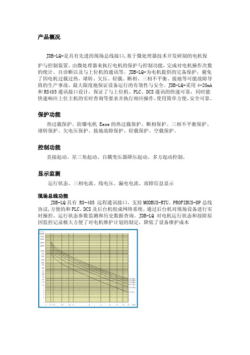
产品概况
JDB-LQ+是具有先进的现场总线接口,基于微处理器技术开发研制的电机保
护与控制装置。
由微处理器来执行电机的保护与控制功能,完成对电机操作次数的统计、自诊断以及与上位机的通讯等。
JDB-LQ+为电机提供的完备保护,避免了因电机过载过热、堵转、欠压、轻载、断相、三相不平衡、接地等可能故障导致的生产事故,最大限度地保证设备运行的有效性与安全。
JDB-LQ+采用4-20mA 和RS485通讯接口设计,保证了与上位机、PLC、DCS通讯的快速可靠,同时能快速响应上位主机的实时查询等要求并执行相应操作。
使用简单方便,安全可靠。
保护功能
热过载保护、防爆电机 Eexe的热过载保护、断相保护、三相不平衡保护、堵转保护、欠电压保护、接地故障保护、轻载保护、空载保护。
控制功能
直接起动、星三角起动、自耦变压器降压起动、多方起动控制。
显示监测
运行状态、三相电流、线电压、漏电电流、故障信息显示
现场总线功能
JDB-LQ具有 RS-485 远程通讯接口,支持MODBUS-RTU、PROFIBUS-DP总线协议,方便的和PLC、DCS及后台机组成网络系统。
通过后台机对现场设备进行实时操控、运行状态参数监测和历史数据查询。
JDB-LQ对电机运行状态和故障原因监控记录极大方便了对电机维护计划的制定,降低了设备维护成本。
电机保护器说明书

EOCR-3DD3DD与外接CT配合时的尺寸图示特点:•内装MCU(MCU)•三只完整的电流互感器•多种保护功能•数字电流表功能•脱扣(动作)原因显示•人工现场复位•电子遥控复位•自检功能•预报警设置功能•适应各种现场环境•电机起动延时(D-TIME),脱扣延时(O-TIME)可独立连续设定。
•失电安全自保(NO VOLT RELEASE)下载使用说明书:EOCR-3DD前调整面板图示:前面板DIP开关组(SW1-SW4):开关编号功能“OFF”关“ON”开SW1安全保护失效有效SW2逆相保护不能进行电机反转保护可以进行电机反转保护SW3动作特性定时限反时限SW4报警见相关介绍保护类型:可保护项目脱扣时间过电流O-TIME缺相4秒(05:1A,60:5A以上时动作)堵转D-TIME反相0.1秒(SW2拨至RPR位置)相间不平衡8秒故障显示:功能(项目)LED显示脱扣原因脱扣延时时间简单描述过电流A相出现5.5A的电流定时限:经过OT设置的时间后。
反时限:按时间--电流特性曲线动作。
负载电流大于预先设定的保护电流值。
逆相相序改变引起电机反转0.1秒内动作SW2置“ON”位缺相B相缺相4秒内动作相不平衡A相出现最小的不平衡电流2.1A8秒[((最大电流-最小相电流)÷最大相电流)]×100%>50%堵转C相出现最大的堵转电流9.5A经过DT设置的时间立即动作(仅用于定时限方式)负载电流大于预先设定的保护电流值的300%时。
报警输出:报警LED显示原因描述顺时针缓缓旋转报警点设置旋钮,显示窗显示“A”闪动,数字“85”,含义是:电机即时负载电流达到继电器预先设置保护电流值的85%。
报警设置值的范围是:50-100%或者关闭报警输出功能,当电机的(即时负载电流÷预先设置保护电流电流)×100>报警设置值时,显示窗显示“A”闪动,并从报警输出继电器(07,08)送出通-断信号。
保护控制器操作使用方法(精)

保护控制器操作使⽤⽅法(精)六、保护控制器操作使⽤⽅法1.⾯板及按键说明 1.1显⽰窗第⼀显⽰窗在参数设定状态下显⽰设定参数;第⼆、第三、第四显⽰窗在运⾏状态下分别显⽰三相电流和三相电压。
1.2指⽰灯⼋个指⽰灯,指⽰电机故障停⽌原因:启动失败、短路堵转、缺相、三相不平衡、定/反时限、接地、⽋过压、1.3按键设置键:在测量(运⾏)状态下,按住2秒钟以上不松开则进⼊设置状态。
在设置状态下,显⽰参数符号时,按住2秒钟以上不松开进⼊下⼀组参数或返回测量状态。
左键:在测量状态下切换显⽰电流、电压。
在设置状态下,⽤于调出原有参数或移动修改位。
确认键、复位键:在测量状态下作为故障恢复键使⽤。
在设置状态下,⽤于存⼊修改好的参数值。
增加键:在设置状态下,⽤于增加参数数值或改变设置类型。
减少键:在设置状态下,⽤于减少参数数值或改变设置类型。
1.4参数设置说明仪表的参数被分为六组,⼆、三、四、五、六组参数受密码控制,未设置密码时不能进⼊。
进⼊设置状态后,若1分钟以上不进⾏按键操作,仪表将⾃动退出设置状态。
1.5参数设置⽅法①设置键,不松开,直到显⽰0A 。
②按键进⼊修改状态,在、键的配合下将数值修改为1111 ③按键,完成密码设置。
④按住设置键,不松开,顺序进⼊下⼀组参数,仪表显⽰每组第⼀个参数的符号。
⑤进⼊需要设置参数所在的组,按键顺序循环选择本组需设置的参数。
⑥按键调出当前参数的原设定值,闪烁位为修改位。
⑦通过键移动修改位、增值、键减值,将参数修改为需要的值。
* 以符号形式表⽰参数值的参数,在修改时,闪烁位应处于末位。
⑧按键存⼊修改好的参数,并转⼊下⼀参数。
⑨重复⑤-⑧步,可设置本组的其他参数:在显⽰参数符号时,按住设置键不松开,直到退出参数的设置状态。
七、参数⼀览表该表列出了仪表的基本参数。
出⼚设定参数只是参考值,⽤户可以根据电机情况进⾏修改。
在出⼚设定⼀栏有“****”号的参数,⽤户必须设定。
⼋.仪表(参数)使⽤说明参数⼀览表说明:注1:电流互感器的选择:建议⼀次电流按电机额定电流的8倍以上选择变⽐,这样有利于保证互感器和仪表的过载能⼒注2:调校:调校可以减少由于互感器、引线等引起误差,提⾼系统的测量精度。
电动机综合保护器(CK200数码管)说明书
键:保护动作后,按此键保护器复位。设置过程中按此键更新已确认的设定数据,返回到等待电机启动状 态。 8.2.运行操作
保护器接入工作电源后,LED 显示额定电流;电动机启动后 LED 显示启动时间倒计时,启动状态过后,进入运行状态,
LED 循环显示三相电流,如:
首位显示电流相代码,后三位显示电流值;此时按任
4.型号说明
CK200-□- □- □
额定电流 3A 8A 20A 50A 100A 200A 300A 400A 500A 600A
--
安装结构 分体式结构 一体式结构
代号 F Y
附加功能 漏电保护 通讯功能 模拟量输出
代号 I S
AO
--
800A
5.工作条件
● 三相穿孔适应回路:AC380V、AC660V ● 工作电源电压:AC220V ● 环境温度:-25℃~+70℃,相对湿度:5%~95% ● 海拔高度不超过 2500 米 ● 大气条件:没有会引起爆炸危险的介质,也没有会腐蚀金属和破坏绝缘性能及导电尘埃 ● 安装在无强烈冲击振动和雨雪侵袭的地方 ● 安装在无强磁干扰的地方,避免与软启动器和变频器一起安装,尽量拉长安装距离
输出供用户选用,当 设置为 001 时,带通信的为通信启动。 出厂设置值 000 或按用户要求而设置。
3、
漏电电流序号
0
1
2
3
4
5
6
7
8
9
≥漏电电流值〔mA〕 1000 950 900 850 800 750 700 650 600 550
漏电电流序号
10
11
12
13
14
15
16
17
18
电动机保护器说明书

电动机保护器说明书1.概述微机监控电机保护器适用于AC380V、AC660V低压系统,作为低压异步电动机和增安型电动机的保护、监测和控制的新一代智能化综合装置。
除了先进的电动机保护、监控功能,还提供了设备运行和跳闸的记录以及额定参数等重要信息,并且采用现场总线方式结构,为现代化的设备管理带来很大的便利;广泛用于石油、化工、电力、冶金、煤炭、轻工、纺织等行业。
符合标准:GB3836.3-2000、GB14048.4-2003、IEC2552.特点●“tE时间保护”符合有关增安型防爆电动机过载保护的国家标准(GB3836.3-2000)●交流采样,测量A、B、C三相电流及控制回路电压●现场显示电动机运行状态,保存三次电动机故障跳闸记录●一路保护输出,一路自定义继电器输出,一路4~20mA电流输出或RS485接口●高清晰度宽温液晶显示,并具有背景光,跟随电动机运行状态和用户要求实时显示●三相电流不平衡、断相、过压、欠压、自启动等功能用户可取可舍●采用E2PROM存储技术,实现参数电设定,掉电后设定参数仍保存下来,勿须再设定●采用RS485通信总线,可广泛用于各种监控系统作为带有电机保护及控制的智能化监控单元●一机多用,可取代电流表、电压表、热继电器、电流互感器、时间继电器和漏电继电器等3.主要功能保护功能:过流、堵转、断相、三相电流不平衡、过压、欠压、短路、漏电(选配)等故障保护测量功能:三相电流、控制回路电压的测量和显示通用功能:增安型电动机保护、三相异步电动机保护、馈线保护,三种保护装置通用通信功能:通过本保护器的RS485接口与上层系统通信。
总线接口支持参数设置、控制及监测等功能,支持Modbus通信协议。
一般采用RS485总线接口进行物理连接,通常上位机或PLC设备作为主站,本保护器作为子站。
电流输出:4~20mA电流输出,20mA对应的电流值可设。
4.型号说明微机电动机保护监控装置适用于AC660V及以下低压系统,作为低压电动机馈线终端的保护、监测和控制的新一代智能化综合装置。
电力电路保护器及电源开关操纵器安装说明说明书
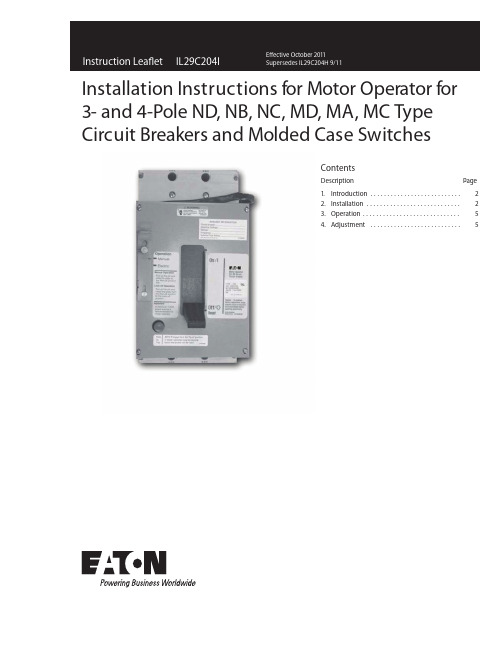
Installation Instructions for Motor Operator for 3- and 4-Pole ND, NB, NC, MD, MA, MC Type Circuit Breakers and Molded Case SwitchesContentsDescription Page1. Introduction (2)2. Installation (2)3. Operation (5)4. Adjustment (5)2Instruction Leaflet IL29C204IE ective October 2011Installation Instructions for Motor Operator for 3- and 4-Pole ND, NB, NC, MD, MA, MC T ypeCircuit Breakers and Molded Case SwitchesEATON CORPORATIONWARNINGCONTACT WITH ENERGIZED EQUIPMENT CANRESULT IN DEATH, SEVERE PERSONAL INJURY, OR SUBSTANTIAL PROPERTY DAMAGE. DO NOT NANCE ON EQUIPMENT WHILE IT IS ENERGIZED. ALWAYS VERIFY THAT NO VOLTAGE IS PRESENT BEFORE PROCEEDING WITH THE TASK, ANDALWAYS FOLLOW GENERALLY ACCEPTED SAFETY PROCEDURES.ATTEMPT TO INSTALL OR PERFORM MAINTE - EATON IS NOT LIABLE FOR THE MISAPPLICATION OR MISINSTALLATION OF ITS PRODUCTS.The user is cautioned to observe all recommendations, warnings, and cautions relating to the safety of personnel and equipment as well as all general and local health and safety laws, codes, and procedures.The recommendations and information contained herein are based on Eaton experience and judgement, but should not be considered to be all-inclusive or covering every application or circumstance which may arise. If any ques- instructions. 1. INTRODUCTIONThe motor operator (Fig. 1-1) allows the circuit breaker to be opened, closed, or reset remotely. It has the capability for lock -off, push -to -trip, and manual operation. Electrical The motor operator mechanism is driven by a reversible electric motor connected to a ball screw. The ball screw drives the circuit breaker handle. Limit switches are used to control the motor.installed to gain access to the breaker’s cable terminals, Fig. 2-3.Fig. 1-1. Motor Operator Installed in ND Type FrameSeries C Circuit Breaker 2. INSTALLATIONThe motor operator is Underwriters Laboratories, Inc. listed as a recognized component suitable for field instal - lation on N -frame circuit breakers and molded case switches under UL File E64124.The motor operator is normally supplied as a separate item for mounting on an uninstalled circuit breaker. If a motor operator is to be mounted on an installed circuit breaker, all power must be removedfrom the circuitIf the motor operator is to be installed on an OPTIM breaker, an OPTIM Connector Kit, Catalog Number be connected on the face of the operator. The kitthe trip unit port.tions arise, contact Eaton for further information or power to the motor is cut off when the cover is removed. It is unnecessary to remove a motor operator onceOPEOPCK, should be ordered to allow the Optimizer to includes a connector socket and an extension cable to breaker before proceeding to mount the motor operator.3Instruction Leaflet IL29C204IE ective October 2011Installation Instructions for Motor Operator for 3- and 4-Pole ND, NB, NC, MD, MA, MC T ypeCircuit Breakers and Molded Case SwitchesEATON CORPORATION WARNINGBEFORE MOUNTING A MOTOR OPERATOR ON A CIRCUIT BREAKER INSTALLED IN AN ELECTRICAL SYSTEM, MAKE S URE THE CIRCUIT BREAKER IS SWITCHED TO THE OFF POSITION AND THATTHERE IS NO VOLTAGE PRESENT WHERE WORK IS TO BE PERFORMED. SPECIAL ATTENTION SHOULD BE PAID TO REVERSE FEED APPLICATIONS TO ENSURE NO VOLTAGE IS PRESENT. THE VOLTAGES IN ENERGIZED EQUIPMENT CAN CAUSE DEATH OR SEVERE PERSONALINJURY.CAUTIONENERGIZING THE MOTOR OPERATOR WHEN IT IS AGE IT. ENSURE THAT THE MOTOR OPERATOR IS SECURELY MOUNTED TO A CIRCUIT BREAKER BEFORE OPERATING ELECTRICALLY.NOT MOUNTED TO A CIRCUIT BREAKER MAY DAM - Note: When the motor operator is mounted to the cir - cuit breaker, the circuit breaker nameplate is not visi - ble. Before mounting the motor operator, make sure the circuit breaker nameplate information is recorded for future reference. A blank nameplate is supplied for this purpose. The nameplate should be placed on the top side of the motor operator.To install the electrical operator perform the following steps:2-1. 2-2. 2-3. 2-4. Remove motor operator from packing. Inspect it forcompleteness (Fig. 2-1). Check the motor operator nameplate to make sure that the rating agrees with the installation requirements; and make sure that mounting hardware is included. Install circuit breaker handle extension using nutsand screws supplied. (See Fig. 2-3.)Assemble top mounting plate (spacer) with 3.75-in.flat head screws supplied (Figs. 2-1, 2-3, 4-2). Motor operator frame is to mount to this top plate motor operator to the circuit breaker with screwsFig. 2-1Motor Operator Kitusing two .500-in. pan head screws. Trip breaker to the "TRIP "e h t t n u o M .n o i t i s o p4Instruction Leaflet IL29C204IE ective October 2011Installation Instructions for Motor Operator for 3- and 4-Pole ND, NB, NC, MD, MA, MC T ypeCircuit Breakers and Molded Case SwitchesEATON CORPORATION ,.Whitsd --DC LEGEND- On Switch-Switch52a-Switch-Breaker AuxiliaryS witch DIAGRAM SHOWS THE CIRCUITAND MOTOR OPERATOR IN ‘OFF’ POSITION.Fig. 2-2. Motor Operator Wiring Diagram D irectionFor tighting breaker cable boflom terminals use the following steps:Remove the motor operator cover Loosen t wo 4 in. pan head mounting screws Remove bottom mounting plate spacer Remove bottom terminal coverTerminal Block Wire Connector Terminal ScrewsWire LeadsFig. Terminal Block and Wire Leadssupplied. Put the bottom mounting plate (spacer) between the motor operator and the breaker (Figs. 2-3 (lt.03)). The roll pin must be in thebase slot and the push nut inside the operator. Use two 4-in. pan head screws. The handle extension must be between the rollers of the bracket assem - bly, and the motor towards the line end of the breaker (Figs. 2-3, 4-1).2-5. 2-6. 2-7. 2-8. The motor operator is equipped with a “PUSH -TO -TRIP” feature. Turn circuit breaker “ON”. Press the “PUSH -TO -TRIP” button to verify that the breaker trips. Reset breaker and turn “ON” again. Replace the cover and cover screws, check the “PUSH -TO - TR I P ” again . The motor operator is equipped with a terminal block and 30-in. long wire leads. If it is desirable to change wire leads, just pull out the wire connector, and connect the new wire leads to the screws or tabs of the terminal block. (See Fig. 2-4 page 3.) If motor operator is used for NB, NC, or MD, MA,MC type circuit breakers and molded case switches the mounting screws must be changed to .190 x 3.375, .190 x 3.625, or .190-32 x 2.25, .190-32 x 1.75 pan head screw with lock washer. To connect the power and control wiring, refer toFig. 2-2, page 3.Fig. 2-3. Terminal Tightening InstructionsP B - O n P u s h b u t t o n52b }Momentary Contacts5Instruction Leaflet IL29C204IE ective October 2011Installation Instructions for Motor Operator for 3- and 4-Pole ND, NB, NC, MD, MA, MC T ypeCircuit Breakers and Molded Case SwitchesEATON CORPORATION 3. OPERATIONNote: The motor operator does not permit a breaker handle to indicate its “TRIP” position. If it is desir - able that the trip position be indicated, the breaker may be equipped with bell alarm contacts which “MAKE” or “BREAK” upon automatic trip operation. Contacts may be wired to an external light or other indicating device to then indicatetrip.CAUTIONMAKE SURE THAT ALL S ENSITIVE EQUIPMENT BREAKER IS DISCONNECTED BEFORE OPERATING THE MOTOR OPERATOR. SWITCHING OPERATIONSCIALLY EQUIPMENT REQUIRING A CONTROLLED SHUTDOWN.COULD CAUSE DAMAGE TO EQUIPMENT -ESPE - Electrical OperationTo check the electrical operation use the remote momen - tary “ON” and “OFF” control devices, and perform the fol - lowing steps: (refer to Fig. 2-2)3-1. Pull up the setting pin and slide the locking arm(white line) to the Electrical Operation mode, (Figs. 3-1 and 3-2). 3-2. Energizing the “OFF” push button will cause thebreaker to go to its “OFF” position. 3-3. Energizing the “ON” push button will cause thebreaker to go to its “ON” position. 3-4. Press the “PUSH -TO -TRIP” button (see Fig. 3-1);verify that the breaker trips. Energizing the “OFF” button, motor operator will “RESET” the breaker. Note: DO NOT use maintain type control switches. Manual O peration3-5. Pull up the setting pin and slide the locking arm(white line) to the Manual Operation mode. In this mode electrical power to the motor is cut off (Figs. 3-1 and 3-3).CAUTIONIF BREAKER IS TRIPPED WHEN OFF, MOTOR OPER - ATOR MUST BE RECYCLED TO ON, THEN RESET BREAKER W ITH UVR DE -ENERGIZED.PLIED WITH BREAKER, DO N OT OPERATE THE 3-6. Using the “HANDLE EXTENSION” to operate themotor operator mechanism,throw to the “ON” and FF” positions . 3-7. Press the “PUSH -TO -TRIP” button to trip the circuit breaker, and verify that the breaker has tripped. Throw the “HANDLE EXTENSION” to the extreme “OFF” position. This should “RESET” the breaker. Lock -off3-8. Pull up the setting pin and slide the locking arm(white line) to the Manual Operation mode. motor operator cannot be locked off while it is in the “ON” position. Power -offThe electrical supply to the motor will be automatically cut off when the cover is removed, and also when using Manual Operation (see paragraph 3-5).4. ADJUSTMENTThe following procedures describe the adjustment of the motor operator limit switches if necessary:Note: The motor operator has been adjusted at the factory. Before attempting to adjust the motor opera - tor, verify that a 5 kVA Power Source for 48 Vdc, 24 Vdc ratings and a 1 kVA Power Source for other rat - ings are being used, and that all installation instruc - tions have been followed. Verify that the circuitbreaker can be operated without the motor operator. Under standard conditions the factory settings should not require field adjustments.CONNECTED TO THE LOAD S IDE OF THE CIRCUIT (OFF), AND BACK TO ON.IF )R V U ( E S A E L E R E G A T L O V R E D N U N A IS SUP - 3-9. Turn the locking arm 90 degrees to the“LOCK-OFF” position (Fig. 3-4) and insert up to 3 padlocks. The6Instruction Leaflet IL29C204IE ective October 2011Installation Instructions for Motor Operator for 3- and 4-Pole ND, NB, NC, MD, MA, MC T ypeCircuit Breakers and Molded Case SwitchesEATON CORPORATION Fig. 3-1. Motor Operator FeaturesFig. 3-2. Motor Operator in Electrical PositionFig. 3-3. Motor Operator in Manual PositionFig. Motor Operator in Lock -Off Position7Instruction Leaflet IL29C204IE ective Octoberr 2011Installation Instructions for Motor Operator for 3- and 4-Pole ND, NB, NC, MD, MA, MC T ypeCircuit Breakers and Molded Case SwitchesEATON CORPORATION Two limit switches control the travel of the motor operator carriage. The upper switch de -energizes the motor when the carriage has moved sufficiently to close the circuit breaker. The lower switch de -energizes the motor when the carriage has moved sufficiently to reset the circuit breaker.4-1. Disconnect the motor operator from the supply volt -age. 4-2. Remove the cover screws and the motor operatorcover. 4-3. Use a .125-in. dia. pin (customer supplied) andinsert into the 30-in. dia. hole near the “POWER- OFF” switch to hold switch “ON” (Figs. 3-1 and 4-1).CAUTION.125 IN. DIA. PIN SHOULD BE REMOVED BEFORE REINSTALLING THE COVER.4-4. For upper limit switch adjustment, loosen the twopan head screws securing the upper switch assem - bly. Move the switch up to increase the carriage travel. Move the switch down to decrease the car - riage travel. After adjusting, tighten the screws.Upper Limit SwitchPower -Off SwitchLower Limit SwitchrFig. 4-1. Motor Operator Limit Switch Locations 4-5. For lower limit switch adjustment, loosen the twopan head screws securing the lower switch assem - bly. Move the switch down to increase the carriage travel. Move the switch up to decrease the carriage travel. After adjusting, tighten the screws. 4-6. Replace the motor operator cover and coverscrews. 4-7. Reconnect the motor operator to the supply volt -age, reset.8Instruction Leaflet IL29C204IInstallation Instructions for Motor Operator for 3- and 4-Pole ND, NB, NC, MD, MA, MC T ypeCircuit Breakers and Molded Case SwitchesEATON CORPORATION Frequency (Hz)Motor -inR ush Current (A) Catalog Number Table 1-1. Available Motor Operator Ratings and Operating Conditions50/6050/60DcDcDc151350Catalog Number Motor -in -Rush Current (A)Style Number15Rated Voltage 120 (1 10)208 240 (220) 125 Vdc Style Number Rated Voltage 120208 240480125 Vdc24 VdcFrequency (Hz) IOperator is an intermittent duty device. The safe duty cycle (OFF to ON to OFF) should not exceed one per minute.Electrical Operating times at rated voltage. a. To turn breaker ON - 0.2 second (12 cycles) max. b. To turn breaker OFF - 0.2 second (12 cycles) max. Motor Operating temperature; Class “A t emperature limits apply. Applied Voltage should be no less than 85% or no more than 11 0% of rated voltage.Operator applications on supply of 480 Vac utilizes a transformer. (Customer Supplied)EOP5T07EOP5T09EOP5T11EOP5T15EOP5T26EOP5T22EOP5T2124 Vdc19 1545519131550480/115 Vac 1484D60G011484D60G021484D60G031484D60G041484D60G05148460G081484D60G031484D60G311484D60G321484D60G331484D60G341484D60G351484D60G369Instruction Leaflet IL29C204IE ective Octoberr 2011Installation Instructions for Motor Operator for 3- and 4-Pole ND, NB, NC, MD, MA, MC T ypeCircuit Breakers and Molded Case SwitchesEATON CORPORATION10Instruction Leaflet IL29C204IE ective October 2011Installation Instructions for Motor Operator for 3- and 4-Pole ND, NB, NC, MD, MA, MC T ypeCircuit Breakers and Molded Case SwitchesEATON CORPORATION Notes:11Instruction Leaflet IL29C204IE ective Octoberr 2011Installation Instructions for Motor Operator for 3- and 4-Pole ND, NB, NC, MD, MA, MC T ype Circuit Breakers and Molded Case Switches EATON CORPORATION Notes:Eaton Corporation Electrical Group1000 Cher rington Parkway Moon Township, PA 15108 United St ates877-ETN-CARE (877-386-2273) © 2011 Eaton CorporationAll Rights ReservedPrinted in US APublication No. IL29C204I / TBG000694 Part No. 6634C87H091102r e b o t c O Eaton is a registered trademark of Eaton Corporation.All other trademarks are property of their respective owners.Instruction Leaflet IL29C204I Installation Instructions for Motor Operator for3- and 4-Pole ND, NB, NC, MD, MA, MC T ypeCircuit Breakers and Molded Case SwitchesThe instructions for installation, testing, maintenance, or repairherein are provided for the use of the product in general commercialapplications and may not be appropriate for use in nuclear applica-to replace, amend, or supplement these instructions to qualify themfor use with the product in saf ety-related applications in a nuclearfacility.This Instr uction Booklet is published solely for information purposesand should not be considered all-inclusive. If further information isrequired, you should consult an authorized Eaton sales represent a-tive.The sale of the product shown in this literature is subject to theterms and conditions outlined in appropriate Eaton selling policiesor other contractual agreement between the parties. This literatureis not intended to and does not enlarge or add to any such contract.The sole source governing the rights and remedies of any purchaserof this equipment is the contract between the purchaser and Eaton.NO WARRANTIES, EXPRESSED OR IMPLIED, INCLUDINGWARRANTIES OF FITNESS FOR A PARTICULAR PURPOSE ORMERCHANTABILITY, OR WARRANTIES ARISING FR OM COUR SEOF DEALING OR USA GE OF TRADE, ARE MADE REGARDINGTHE INFORMA TION, RECOMMEND ATIONS, AND DESCRIPTIONSCONTAINED HEREIN.In no event will Eaton be responsible to the purchaser or user incontract, in tort (including negligence), strict liability or other wisefor any special, indirect, incidental or consequential damage or losswhatsoever, including but not limited to damage or loss of use ofequipment, plant or power system, cost of capital, loss of power,additional expenses in the use of existing power facilities, or claimsagainst the purchaser or user by its customers resulting from theuse of the information, recommendations and description containedherein.E ective October 2011。
德力西 JD-5 系列电动机综合保护器说明书

JD Series Motor Integrated ProtectorUser Manual □Перед установкой и использованием продукции внимательно прочитайте руководство по эксплуатации и храните его в надежном месте.I. Overview1.1 Scope of ApplicationJD series motor integrated protector is suitable for AC 50/60Hz and voltage 380V and below power supply circuit to form a motor control circuit together with the switch circuit such as AC contactor. When the main circuit of motor is in the abnormal working state such as phase loss, overload or stall, it can disconnect the electrical contact of switch in time and break the three-phase power supply of motor to protect the motor reliably.Standard: GB/T14048.41.2 Model DefinitionRated control supply voltage Us:AC220V;AC380VRated current: see tableCommon type if not marked;B: With an alarmA: Setting current scale calibrationDesign No.: see TableIntegrated protector for electric motor1.3 Normal Working conditions and Installation Conditions1.3.1 Ambient environment: The altitude does not exceed 2000 meters; The ambient temperature is not higher than +40°C and not lower than -5°C; the voltage change range of the rated control power supply is 85%-110% of the rated voltage; the product is installed in a medium without serious vibration or explosion hazard, and there is no enough gas or dust to cause corrosion to the metal or damage to the insulation in the medium; installed in a place where there is no rain or snow erosion.1.3.2 Vertical or horizontal installation.II. Structural Characteristics and Working PrincipleThe integrated protector for JD series electric motor designed with small division, high protection precision, reasonable structure, complete function, and convenient operation according to the motor power characteristics. The protector has protection functions for symmetrical faults (such as overload and stall) and for asymmetric fault such as phase loss; this protector adopts current sensing technology and relay output interface, and the entire series is of the core-through type. This protector features with simple structure, reliable action, convenient operation, and low cost.III. Technical parametersTechnical parameters of JD-5, JD-5B, JD-6:ModelParameterJD-5 JD-5B JD-6Rated operating current Ie range 0.5-5A 2-20A 20-80A1-80A 1-100A63-150A 63-400A100-250A 250-500ARated insulation voltage Ui AC380VRated opearting voltage Ue AC380VRated control power voltage Us AC50/60Hz AC220V AC380VUsage category Main circuit AC-3; matched auxiliary contact (body) AC-15 Housing protection grade IP40 IP50Type and qty. of aux. circuits 1 normally-closed 1 normally-open 1 normally-closed Operating voltage and operatingcurrent under the usage categoryof auxiliary circuitAC-15 Ue” AC220V Ie: 0.47ARated limit short-circuit currentmatching SCPDRT16-00, 6ATrip grade 10AOverload proteciton characteristics The actual operating current of motor is 1.05 times rated operating current, the action protection time of protector is greater than or equals to 2h; when the actual operating current rises to 1.2 times, the action protection time of protector is less than 2h; when the acutal operating current rises to 1.5 times, the action protection time of protector is less than 2 minutes; when the actual operating current of motor is 7.2 times rated operating current, the action protection time of protector is greater than 2s, and less than or equals to 10s.Phase loss time Loss of any phase in three phases ≤ 3sContact capacity AC380V, 3A: AC220V, 5A (resistive)Electrical life: ≥10 x 104 timesMechanical life ≥10 x 104 timesInstallation method Device type (with TH35 mounting rail or screw fixed installation used)Technical parameters of JD-5A, JD-6A:ModelParameterJD-5A JD-6ARated operating current Ie range0.5A-5A 2A-20A 2A-10A8A-40A 10A-100A 20A-10020A-100A (5 and 6 breaking)100A-400A (5 and 6 making)Rated insulation voltage Ui AC380VRated opearting voltage Ue AC380VRated control power voltage Us AC50/60Hz AC220V AC380VUsage category Main circuit AC-3; matched auxiliary contact (body) AC-15 Housing protection grade IP40 IP50Type and qty. of aux. circuits 1 normally-closed 1 normally-open 1 normally-closed Operating voltage and operatingcurrent under the usagecategory of auxiliary circuitAC-15 Ue: AC220V Ie: 0.47ARated limit short-circuit currentmatching SCPDRT16-00, 6AOverload time Trip grade 1.2 times 1.5 times 7.2 times10 Tp<2h Tp≤4min 4<Tp≤10sPhase loss time Loss of any phase in three phases ≤ 6sContact capacity AC380V, 3A: AC220V, 5A (resistive)Reset Power outage reset and not less than 300s Electrical life: ≥10 x 104 timesMechanical life ≥10 x 104 timesInstallation method Device type (with TH35 mounting rail or screw fixed installation used) Note: 1. When the rated current of the motor is lower 2A for JD-5A, wind the Phase A and Phase C more turns (holes on both sides of protector) to ensure that the core-through current is not below 2A.2. When the setting current of the protector of JD-6A motor is ranged from 20A to 100A, the pins 5 and 6 of protector are disconnected; when the rated current of motor is greater than 100A, the pins 5 and 6 of protector are connected through a wire, and the setting value shown on the scale dial is 100 to 400A.JD-5A, JD-5, JD-5B Performance Difference TableModelFunctionJD-5A JD-6AJD-5JD-5B JD-6Phase loss proteciton The working power supply and three-phase current can be turned on asynchronously, suitable forstar-delta conversion, with phaseloss protection not provided for non-load at the moment of conversion.The working power supply andthree-phase current shall be turned on synchronously, not suitable for star-delta conversion, with phase loss protection provided for non-load at the moment of conversion.Setting modeCalbricated scale; static setting is performed according to the ratedcurrent of motor for accurate, intuitive and convenient operation. Setting the current can be performed only when the motor is running without calbricated scale. Overload characteristics With motor start timeout protection,and with start time adjustment. The overload inverse limit range is small, unable to adjust the trip grade.IV. Outline and Installation DimensionsJD-5. JD-5A, JD-5B Outline and Installation Dimension DrawingJD-6 Outline and Installation Dimension DrawingV. Installation and Operation InstructionsJD-5, JD-5B, and JD-6 installation and operation instructions:1. Please read the user manual carefully and connect the wire correctly according to the wiring diagram.2. Terminals 1 and 2 are the working power input terminals of the protector; JD-5 and JD-5B: 3 and 4 are normally closed contacts at the output control terminal; JD-6: 5 and 6 are the normally closed contacts at the output control terminal, and 4 and 5 is the normally open contacts at the output control terminal. For wiring method, refer to the wiring diagram; the three wires of output terminal of AC contactor pass through three white wire holes H1, H2, and H3 of the protector respectively to connect with the inlet wires of motor. (Refer to the wiring diagram).3. Turn the two adjusting knobs on the protector panel clockwise to the maximum, and turn on the power supply after confirming that the wire is connected properly. Press the Start button and run the motor (the green light is on and the phase loss yellow light is not on, and the overload red/green light is on when normal operation). When the product is running normally, turn the current adjusting knob counterclockwise until the overload indicator flickers, and then fine adjust it clockwise to the critical position where the overload lamp does not flicker; observe it for about 3 minutes. During this period, the current or motor and load are normal, and the overload indicator does not flicker, and then turn the delay button back counter clockwise to the position greater than the motor start time (longer is preferred).4. When the motor works normally, the overload light is not on, and the motor is applied with load manually, andat this time, the overload lamp will flicker, so the entire debugging process is completed.Protector ProtectorNote: AQ: Start Note: QA: StartTA: Stop TA: StopKM: AC contactor 220V KM: AC contactor 380V(JD-5(B) and BHQ-S-J have the same wiring) (JD-5(B) and BHQ-S-J have the same wiring) JD-5, JD-5B: AC220V JD-5, JD-5B: AC380VWiring diagram Wiring diagramProtectorProtectorNote: AQ: Start Note: QA: StartTA: Stop TA: StopKM: AC contactor 220V KM: AC contactor 380VJD-5A: AC220V JD-5A: AC380VWiring diagram Wiring diagramNote: AQ: Start Note: QA: StartTA: Stop TA: StopKM: AC contactor 220V KM: AC contactor 380VJD-6: AC220V JD-6: AC380VWiring diagram Wiring diagramSpecification conversion Specification conversion Note: AQ: Start Note: QA: StartTA: Stop TA: StopKM: AC contactor 220V KM: AC contactor 380VJD-6A: AC220V JD-6A: AC380VWiring diagram Wiring diagramVI. PrecautionsJD-5A:1. Correct wire according to the wiring diagram.2. Adjust the current setting potentiometer to align the pointer with the corresponding calibration scale according to the rated current marked on the nameplate of the motor.3. Start the motor, and the overload indicator is on. After startup, the overload indicator shall be off during normal operation, so the adjustment process is completed.JD-5 and JD-5B:1. When debugging the current knob, it shall be carried out when a change of the rated working voltage is less than ±5%.2. For motors with a line current of less than 6A, the three-phase power line should be wound onto the white wire hole of the protection by considering that the non-load line current of motor is smaller. Technical characteristics should be met.3. Due to the internal structure relationship, the overcurrent adjustment scale is not linear, and the actual debugging shall prevail.4. Regularly check the performance of the protector, such as phase loss test and overload test.5. It is strictly forbidden to increase the reading on the current potentiometer of the protector when the current and motor or load are not normal, otherwise the motor may be easily burnt.6A and above 3A~6A, H2 1A~3A,First wire winding Second wire winding H1, H2, H3Third wire windingJD-5 and JD-5B wire winding diagramJD-6A:1. Correct wire according to the wiring diagram.2. Adjust the current setting potentiometer to align the pointer with the corresponding calibration scale according to the rated current on the nameplate of the motor. Wind the wires three turns for 2A and below current A and C phases.3. Start the motor, and the overload indicator is on. After startup, the overload indicator shall be off during normal operation, and the adjustment process is completed.JD-6:1. When debugging the current knob, it shall be carried out when a change of the rated working voltage is less than ±5%.2. For motors with a line current of less than 63A, the three-phase power line should be wound onto the white wire hole of the protection by considering that the non-load line current of motor is smaller. Technical characteristics should be met.3. Due to the internal structure relationship, the overcurrent adjustment scale is not linear, and the actual debugging shall prevail.4. Regularly check the performance of the protector, such as phase loss test and overload test.5. It is strictly forbidden to increase the reading on the current potentiometer of the protector when the current and motor or load are not normal, otherwise the motor may be easily burnt.6. For equipment that may cause major economic losses or personal safety, make sure that the technical characteristics and performance values have sufficient margin in design, and safety measures such as doublecircuit protection should be adopted.VII. Common Faults and Solutions1.If the motor stops during normal operation, carefully check the motor for phase loss or overload; first check whether the motor temperature is very high, and this may be overload stop due to temperature rise; if there is no temperature rise, the line phase loss may occur, causing trip, and check whether the three-phase power supply works normally, whether the moving and fixed contacts of AC contactor have good contact, whether three power lines of motor are loose; if the motor still fails to start when all are in the normal state, carefully check whether the connecting screws of self-lock contacts of AC contactor and of normally-closed contacts of protector are loose, and then start and run the motor only after all faults are eliminated. Do not start the motor mandatorily if any fault is not solved to prevent accidents.2.The protector, motor and load switch (such as contactor) shall be used together, and their power supplies are connected simultaneously. If failed to connect the power supply simultaneously, the phase loss failure of protector will occur, and the motor cannot start normally.3.In case of failure of product, first disconnect the power supply, and find out the fault cause; operate the product according to the installation instruction after checking the line works normally.4.For product with poor quality, please contact the local dealer or our company.VIII. Transportation and StorageThe product is not affected by rain or snow during storage and transportation, and cannot be extruded, and should be put in well-vented place during storage; the relative humidity does not exceed 90% at (25°C± 5°C). The lower limit of temperature is -25°C and the upper limit is +55°C.IX. Unpacking and InspectionUnpack the outer paper carton and check that there is a user manual in the packing box.V. Ordering NoticeJD-5 and JD-5B products have the exactly same performance except that the JD-5B has one more failure alarm buzzer compared with the JD-5. JD-5 current is 1-80A; 0.5-5A; 2-20A; 20-80A; the JD-5A current is 2-10A; 8-40A; 20-100A;The JD-6 current is 63-400A, 63-150A, 100-250A, 200-500A; when selecting the model, note that the power of motor is consistent with that of the protector.When ordering, please specify the model and specification of the product. If you have special requirements, please contact the manufacturer.XI. Company CommitmentUnder the condition that users follow the use and storage conditions and the product are well sealed, within 24 months from the production date, our company will provide repair and replacement service free of charge for any damage or abnormal operation due to poor manufacture quality. A paid repair will be provided if the warranty period expires. For any damage due to one of the following situations, a paid repair will be given even if within the warranty period:(1)Improper operation, maintenance, or storage;(2)Modified without permission or improper repair;(3)Damage due to falling off or caused during installation after purchase;(4)Force majeure such as earthquakes, fires, lightning strikes, abnormal voltages, and secondary disasters;(5) The electrical life of the product exceeds 100,000 times; the mechanical life is more than one million times. If you have any question, please contact the dealer or our company’s customer service department.Customer service hotline:400-826-8008Certificate DELIXI ELECTRIC LTD Name: Motor Integrated ProtectorModel: JD SeriesThis product complies with the GB/T 14048.4 standard, and passes the inspection and is allowed to be shipped. Inspector: Check 01Production date: See label on inner boxDELIXI ELECTRIC LTDAddress: Delixi High-Tech Industrial Park, Liushi Town, Leqing City, Zhejiang P/C: 325604 Tel: (86-577) 6177 8888Fax: (86-577) 6177 8000Customer Service hotline: 400-826-8008The first edition of this manual was issued on August 2021.。
德力西 CDBXLE-125大电流漏电保护断路器 说明书

CDBXLE-125 使用说明书安装、使用产品前,请仔细阅读使用说明书,并妥善保管备用。
安全告知在安装、操作、运行、维护、检查之前,请务必认真阅读本说明书,并按照说明书上的内容准确安装、使用本产品。
危险:●严禁湿手操作断路器;●使用中,严禁触摸导电部位;●维护与保养时,必须确保产品不带电;●严禁用短路的办法来测试产品;注意:●安装、维护与保养时,应由具有专业资格的人员操作;●三极、四极产品仅适用于三相系统电源;●产品的各项特性出厂时已整定,使用中不能自行拆装或随意调节;●使用前请确认产品额定电压、额定电流、频率及特性是否符合工作要求;●为防止相间短路,应对接线端裸露导线或铜母线进行绝缘处理;●如需测试绝缘电阻或工频耐压,必须先将电流回路之间的电子元件断开,否则将损坏产品性能;●本产品只对负载端产生的漏电故障提供保护;●对少接线、错接线,本产品不能起到漏电保护作用;●如果产品在开箱时有破损或异常响声,应立即停止使用并联系供应商;●本产品不适用于电动机频繁启动、电热设备、电容柜、高感性、高容性负载和高温环境等特殊场合;●产品报废时,请做好产品废弃物处理,谢谢您的合作。
目录1主要用途及适用范围 (1)2产品型号及含义 (1)3正常使用、安装及运输条件 (2)4技术特性 (2)4.1主要技术性能参数 (2)4.2其它技术参数 (3)5外形及安装尺寸 (3)6安装和使用(维护) (4)7故障分析 (5)8开箱检查 (6)9公司承诺 (6)1主要用途及适用范围CDBXLE-125系列剩余电流动作断路器(以下简称剩余电流动作断路器)具有漏电(触电)、过载、短路等保护功能,还可根据用户的需要增加过压和欠压保护功能。
该剩余电流动作断路器主要适用于交流50/60Hz,额定电压230V/400V、240/415V,额定电流至125A及以下的线路中,用来对人的间接接触提供保护,以及对建筑物及类似的线路进行过电流保护。
带过压保护的剩余电流动作断路器还能对由于电网故障引起电压过度升高进行保护。
JDB-YE+使用说明 使用手册

过载
堵转
相不平衡
轻载
漏电
欠压
启动超时
其他说明
1、模拟量 4 ~ 20mA 接口: 20mA 对应于 JDB-YE+M 监控器过载电流设定值的 2 倍。 例:过电流设定值为 15A 时,20mA 所对应的电流值15A×2=30A 即量程为:0~30A
型号说明
JDB-YE+ T
L
馈 电 保 护( 线 路 保 护 )
B=报警 功能 Q=启停控 制 Y=预 警 功 能 △=星 三 角(自 耦 )起 动 J=接 地短 路输 出
T = R S 4 8 5通 信 接 口 M=4~20mA模 拟量 输出 基本规格代号数字 表示额定电流值 产品系列号
面板示意图
SHDQ
技术说明,如有变更恕不另行通知
1、 长 按 功 能 键 3 秒 以 上 一 次 , 进 入 设 置 菜 单 。过 载 电 流 保 护 值 设 定 : 显 示器右 边显示红色 按移位键 选 择 设 定 字 位 ,该 位 闪 烁 再 按 数 据 键 修 改参 数。 设 置 范 围 按 规 格 表 电 流 值。设置值一般用户按电机铭牌上 的额定电流值设置。
PUCHENG
产品概况
JDB-YE+ 系列智能保护监控器(以 下简称:监控器)。是我公司在十多 年研制生产电机保护产品经验的积累 和现代高科技的结晶。核心部件采用 国外最新型的单片微机,它具有抗干 扰能力强、工作稳定可靠、精度高、 保护参数设定简单方便和数字化、智 能化、网络化等特点。可满足更高层 次用户的要求。它适用于冶金、化工 建材、纺织、电力等工业电动机及三 相电力馈电系统,作过载、轻载、缺 相、过压、欠压、堵转 短路、漏电、 及三相电路不平衡保护和 多方启停控 制。本机具有 RS-485 远程通讯接口 支 持 MODBUS-RTU、 协 议 和4~20 mA模 拟 量 输 出 接 口 , 方 便 的 和PLC、 DCS及 后 台 机 组 成 网 络 系 统 。 通 过 后 台机对现场设备进行操控、运行状 态 监视和历史数据查询。
安迪顿电路断路器和电机保护器短路开关操作指南说明书
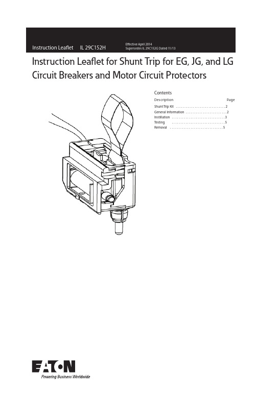
Contentseg a Pn o i t p i r c s e D Shunt Trip Kit .............................2General Information ........................2Instillation ...............................3Testing ...............................5Removal . (5)Instruction Leaflet for Shunt Trip for EG, JG, and LGCircuit Breakers and Motor Circuit Protectors2Instruction Leaflet IL 29C152HE ective April 2014Instruction L eaflet f or S hunt Trip f or E G, J G, a nd L GCircuit Breakers and Motor Circuit ProtectorsEATON Table 2-1 Shunt Trip Application and Electrical Operating Rating Data.The Shunt Trip allows a circuit breaker to be trippedremotely by applying a voltage to the wire leads. The unit consists of an intermittent solenoid with a trippingplunger and a cutoff switch, and is mounted so that whenthe solenoid is energized, the trip lever presses against the trip bar and trips the circuit breaker. As the breaker trips, the molded crossbar moves away from the cutoff switch, disconnecting power to the solenoid and prevent-ing coil burnout.Maximum operations per minute: 5Maximum operating voltage: 110% of maximum voltage range ratingFigure 1-1 Shunt Trip Kit.Figure 2-1 Shunt Trip Connection Diagram.This style requires the use of the Black Cap ONLY for JG Breakers3Instruction Leaflet IL 29C152HE ective April 2014Instruction L eaflet f or S hunt Trip f or E G, J G, a nd L GCircuit Breakers and Motor Circuit ProtectorsEATON WARNINGDO NOT ATTEMPT TO INSTALL OR PERFORM MAINTENANCE ON EQUIPMENT WHILE IT IS ENERGIZED.DEATH OR SEVERE PERSONAL INJUR Y CAN RESULT FROM CONTACT WITH ENERGIZED EQUIPMENT.ALWAYS VERIFY THAT NO VOLTAGE IS PRESENT BEFORE PROCEEDING. AL WAYS FOLLOW SAFETY PROCEDURES. EATON IS NOT LIABLE FOR THE MISAPPLICATION OR MISINSTALLATION OF ITS3.0 INSTALLATION4Instruction Leaflet IL 29C152HE ective April 2014Instruction L eaflet f or S hunt Trip f or E G, J G, a nd L GCircuit Breakers and Motor Circuit ProtectorsEATON .45 - .56 NmWire routing options.Re-install breaker cover.Re-install breaker cover.Route wires.Nm in-lb)(4-5 in-lb)m N 31.1-09.0(8-10 in-lb).79 -.90(7-85Instruction Leaflet IL 29C152HE ective April 2014Instruction L eaflet f or S hunt Trip f or E G, J G, a nd L GCircuit Breakers and Motor Circuit ProtectorsEATON in Section 3.0, step 1.Figure 5-1 Shunt Trip removalFigure 3-5 Accessory Identification and Circuit Diagram label application6Instruction Leaflet IL 29C152HE ective April 2014Instruction L eaflet f or S hunt Trip f or E G, J G, a nd L GCircuit Breakers and Motor Circuit ProtectorsEATON NOTES:7Instruction Leaflet IL 29C152HE ective April 2014Instruction L eaflet f or S hunt Trip f or E G, J G, a nd L GCircuit Breakers and Motor Circuit ProtectorsEATON NOTES:Instruction Leaflet IL 29C152H E ective April 2014Instruction L eaflet f or S hunt Trip f or E G, J G, a nd L G Circuit Breakers and Motor Circuit ProtectorsEatonElectrical Sector1111 Superior Ave. Cleveland, OH 44114 United States877-ETN-CARE (877-386-2273) © 2014 EatonAll Rights ReservedPrinted in Dominican Republic Publication No. IL 29C152H / TBG001132 Part No. 66C1576H09April 2014Eaton is a registered trademark.All other trademarks are property of their respective owners.The instructions for installation, testing, maintenance, or repair herein are provided for the use of the product in general commercial applications and may not be appropriate for use in nuclear applica-tions. Additional instructions may be available upon speci c request to replace, amend, or supplement these instructions to qualify them for use with the product in safety-related applications in a nuclear facility.The information, recommendations, descriptions, and safety nota-tions in this document are based on Eaton’s experience and judg-ment with respect to Retro tting of Power Breakers. This instruction-al literature is published solely for information purposes and should not be considered all-inclusive. If further information is required, you should consult an authorized Eaton sales representative.The sale of the product shown in this literature is subject to the terms and conditions outlined in appropriate Eaton selling policies or other contractual agreement between the parties. This literature is not intended to and does not enlarge or add to any such contract. The sole source governing the rights and remedies of any purchaser of this equipment is the contract between the purchaser and Eaton. NO WARRANTIES, EXPRESSED OR IMPLIED, INCLUDING WARRANTIES OF FITNESS FOR A PARTICULAR PURPOSE OR MERCHANTABILITY, OR WARRANTIES ARISING FROM COURSEOF DEALING OR USAGE OF T RADE, ARE MADE REGARDINGTHE INFORMATION, RECOMMENDATIONS, AND DESCRIPTIONS CONTAINED HEREIN. In no event will Eaton be responsible to the purchaser or user in contract, in tort (including negligence), strict liability or otherwise for any special, indirect, incidental or conse-quential damage or loss whatsoever, including but not limited to damage or loss of use of equipment, plant or power system, costof capital, loss of power, additional expenses in the use of existing power facilities, or claims against the purchaser or user by its cus-tomers resulting from the use of the information, recommendations and description contained herein.。
电机保护器说明书(MAM-B)
11、电源功耗:小于1.5VA;
12、降压起动转换时间:0~999秒;降压起动转换电流:0~999安。
六、结构尺寸与接线端子
图2、接线端子排列
端子:1、2为保护输出,3、4为报
警输出,5、6为电源,7、8为
控制输出(可选为常开或常闭)。
注:接线时请按保护器的功能及相应的接线
注意:所配互感器一定要为次级额定电流为5A的互
感器,如300/5、200/5互感器等。
3、用于Y—△起动控制与保护(图6)
工作原理:
a、起动:按起动键QA,接触器C1线圈得电动作,接触器C2线圈得电动作,电机开始起动,主回路有电流流过。当保护器检测到主回路有电流时,立即计时,计时时间到,保护器常闭触点(7、8)断开2秒,接触器C1失电,接触器C3马上得电,C1被C3一直失电,实现Y—△起动控制。
2、对于有Y—△转换电路,保护器应安装在能测电机线电流的地方,以便按电机铭牌设定。
3、正确设定保护器的设定电流,由于保护器已按设定电流的1.2倍作为过载计算,所以应按电机的
铭牌额定设定。特别注意具有△/Y两种接法的电机,铭牌有两种接法的额定电流,选型和安装
时都要注意这一情况。
4、保护器应工作在正常电流范围内。
以上为只带起动控制功能保护器的基本操作,带欠载等其它功能时操作略有不同。
注:在设定状态,10秒内如无任何操作,保护器返回停机状态,数据不被保存。如修
改完某项数据,只要按住“M”键2秒就可保存修改值。
2、运行状态数据查看
电机起动运行后,监控器将循环显示A、B、C三相电流值和电机额定电流值。如需暂停循环显示可按“”键,如需恢复循环显示可再一次按“”键。但在运行状态下的保护参数是不可修改的。
德力西 JD-6 系列电动机综合保护器 说明书

六、操作注意事项十、订货须知十一、公司承诺在用户遵守、使用、保管条件及产品封印完好的前提下,自产品生产日期起二十四个月内,产品如因制造质量问题发生损坏或不能正常使用的,本公司负责无偿修理或更换。
超过保修期的,需有偿修理。
但因下述情形引起损坏的,即使在保修期内亦做有偿修理:(1) 因使用、维护、保管不当的;(2) 自行改装、不适当修理的;(3) 购买后由于摔落及安装过程中发生损坏的;(4) 地震、火灾、雷击、异常电压及二次灾害等不可抗 力的;(5) 产品使用电寿命超过10万次;机械寿命超过100万次 的。
如有问题请与经销商或本公司客户服务部门联系。
客户服务热线400-826-8008地址: 浙江省乐清市柳市镇电器城3单元 邮编: 325604电话: (86-577)6177 8888传真: (86-577)6177 8000客服热线: 400-826-8008本使用说明书自2018年11月 第一版生产厂:一、概述1.1 适用范围JD系列电动机综合保护器,适用于交流50/60Hz,电压380V及以下的供电电路中与交流接触器等开关电路组成电动机控制电路。
当电动机的主电路出现断相、过载、堵转等非正常工作状态时,能及时断开开关电器触头,分断电动机三相电源,可靠地保护电动机。
1.2 型号定义额定控制电源电压Us : AC220V ; AC380V 额定电流:见表无标注为普通型; B :自带报警;A :整定电流刻度标定设计序号:见表电动机综合保护器二、结构特征与工作原理JD -5A 、JD -6A 技术参数:过载时间JD 5A-2A-10A 8A 40A20A-100-JD 6A-20A ~400A (5、6断开电流规格20A ~100A ;5、6接通电流规格100A ~400A )三相任意一相断相≤6s 断电复位且不小于300s脱扣级别10A 102030在电流整定值倍数下的脱扣时间Tp1.2倍Tp <2h Tp <2h Tp <2h Tp <2h1.5倍Tp ≤2min Tp ≤4min Tp ≤8min Tp ≤12min7.2倍2s <Tp ≤10s 4s <Tp ≤10s 6s <Tp ≤20s 9s <Tp ≤30sJD-5A、JD-5JD-5B 性能差异表、及JD -6、JD -6A 功能型号断相保护整定方式过载特性JD-5A JD-5、JD-5B 、JD-6工作电源和三相电流可异步接通供给,适合星-三角转换,在转换瞬间空载不会断相保护。
WDB系列微机监控电机保护器安装使用说明书(精)

WDB系列微机监控电机保护器使用及设置说明WDB系列微机监控电机保护器是国内低压电机保护器的最新产品,参数测量精度高,保护功能齐全,参数显示直观,我厂在同步电动机及异步电动机的辅助油泵上广泛应用,为规范保护定值的设定,避免保护装置误动作,便于装置的维护和管理,特制定本说明,望班组认真学习,遵照执行。
一、型号规格1、型号◆WDB—A型微机监控电机保护器,该保护器具有对电机进行检测、控制、显示及保护等功能。
◆WDB—B型型微机监控电机保护器,该保护器由主机与显示器组成,主机与显示器设定及显示各种参数,适用于对远距离电机进行检测、控制,主机与显示器之间距离≤1200米。
◆WDB—C型型微机监控电机保护器,该保护器增加了RS485串行数字接口,一台PC机可对256台保护器各种参数进行检测、控制和显示。
2、规格选择见表33.使用原则:①压缩机辅机②系统单机组③系统内双机组切换可能造成系统波动、减量④55KW以上电机(没有安装GL过流继电器二、主要功能1、保护功能:过流、堵转、三相电流不平衡、断相、过压、欠压、漏电、短路等保护。
2、设定功能:可现场设定额定电流值,启动时间、过压值、欠压值、过流动作时间、堵转电流对额定电流的倍数及特殊规定的自启动时间、漏电电流值及地址号。
3、显示功能:通电时显示电压值,检测状态时循环显示A、B、C三相电流值,保护状态时过流、过压、欠压值记忆显示,故障各类别字符提示显示,设置状态时显示各故障字符及设定值。
4、通信功能:通过串行数字接口,实现信息传送,一台PC机可接256台保护器,并可对每台电机进行参数设定、启动操作,便于自动化管理。
三、主要技术指标1、测量范围:电流0—9999A、电压AC150—AC500V。
2、测量精度:1.5级。
3、保护触点容量:AC220V/5A、AC380V/3A,电寿命≥105次。
4、启动时间整定范围:1—99S,在启动时间内,只对断相、过压、欠压、漏电、短路及三相电流不平衡进行保护。
艾顿 JDB3200WA02S30 系列 C 完整封装电路保护器说明说明书
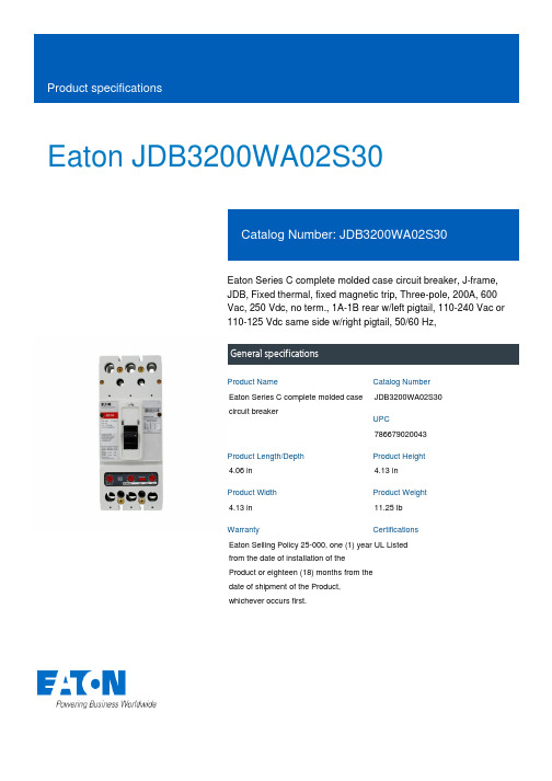
Eaton JDB3200WA02S30Eaton Series C complete molded case circuit breaker, J-frame, JDB, Fixed thermal, fixed magnetic trip, Three-pole, 200A, 600 Vac, 250 Vdc, no term., 1A-1B rear w/left pigtail, 110-240 Vac or 110-125 Vdc same side w/right pigtail, 50/60 Hz,General specificationsEaton Series C complete molded case circuit breakerJDB3200WA02S307866790200434.06 in 4.13 in 4.13 in 11.25 lb Eaton Selling Policy 25-000, one (1) year from the date of installation of the Product or eighteen (18) months from the date of shipment of the Product, whichever occurs first.UL Listed Product NameCatalog Number UPCProduct Length/Depth Product Height Product Width Product Weight WarrantyCertifications35 kAIC at 480 Vac65 kAIC at 240 VacJ200 AThree-poleSeries CComplete breakerJDB110-240 Vac or 110-125 Vdc right pigtail same side 50 to 60 HzComplete breakerWithout terminals600 Vac, 250 Vdc1A-1B rear with left pigtailFixed thermal, fixed magnetic Application of Tap Rules to Molded Case Breaker TerminalsUL listed 100%-rated molded case circuit breakersApplication of Multi-Wire Terminals for Molded Case Circuit BreakersCircuit breaker motor operators product aidPlug-in adapters for molded case circuit breakers product aid Current limiting Series C molded case circuit breakers product aid Multi-wire lugs product aidPower metering and monitoring with Modbus RTU product aid Motor protection circuit breakers product aidStrandAble terminals product aidBreaker service centersMolded case circuit breakers catalogEaton's Volume 4—Circuit ProtectionCircuit Breakers ExplainedCircuit breakers explainedSeries C G-Frame molded case circuit breakers time current curves MOEM MCCB product selection guideSeries C J-Frame molded case circuit breakers time current curves Series C F-Frame molded case circuit breakersEaton Specification Sheet - JDB3200WA02S30Interrupt ratingFrameAmperage Rating Number of polesSeriesTypeCircuit breaker type Shunt tripFrequency ratingCircuit breaker frame type TerminalsVoltage ratingAuxiliary switchTrip Type Application notesBrochuresCatalogsMultimediaSpecifications and datasheetsEaton Corporation plc Eaton House30 Pembroke Road Dublin 4, Ireland © 2023 Eaton. All Rights Reserved. Eaton is a registered trademark.All other trademarks areproperty of their respectiveowners./socialmedia。
