燃料电池应用手册(横河)JAPAN
燃料电池分类及应用

燃料电池分类及应用燃料电池是一种直接将化学能转换为电能的装置,其工作原理是利用氢气与氧气在催化剂的作用下发生氧化还原反应,产生电能和水。
燃料电池根据催化剂的不同可以分为若干个分类,常见的有酸性燃料电池、碱性燃料电池、聚合物膜燃料电池等。
酸性燃料电池(PEMFC)是最早、也是最具发展前景的燃料电池技术之一。
其催化剂通常采用贵金属(如铂类)催化剂,质子交换膜作为电解质,常使用质子交换膜燃料电池(PEMFC)称呼。
酸性燃料电池的工作温度较低,通常在60-90摄氏度之间。
它具有启动快速、高功率密度、响应速度快、能量转化效率高等特点,因此被广泛应用于汽车、航空航天等领域。
碱性燃料电池(AFC)采用碱性电解质,如氢氧化钾溶液。
其催化剂通常采用铂或镍。
碱性燃料电池的工作温度通常较高,常在50-100摄氏度之间。
碱性燃料电池具有较好的电化学活性和稳定性,然而其难以处理碱性电解质和金属催化剂间的腐蚀问题限制了其实际应用。
聚合物膜燃料电池(PEFC)是一种基于固体聚合物电解质的燃料电池,也称为固体聚合物电解质燃料电池。
与酸性燃料电池类似,PEFC也采用了质子交换膜作为电解质。
PEFC的工作温度通常较高,可达80-140摄氏度。
PEFC具有瞬态响应快、能量转换效率高、启动时间短等优点,但其对纯净氢气的纯度要求较高。
除了以上三种主要的燃料电池分类,还有磷酸燃料电池(PAFC)、碳酸盐燃料电池(MCFC)、氟化物燃料电池(SOFC)等。
磷酸燃料电池(PAFC)使用磷酸液体作为电解质,温度较低,常在150-210摄氏度之间工作,适用于用于大型发电系统。
碳酸盐燃料电池(MCFC)的电解质是碳酸盐盐类溶液,工作温度较高,通常在600-800摄氏度之间,具有高效率、高热功率的特点,但由于温度高,应用范围较为局限。
氟化物燃料电池(SOFC)采用氟化物固体作为电解质,工作温度较高,通常在600-1000摄氏度之间,具有高效率、瞬态响应快等特点,但也面临耐高温和材料选择等方面的技术难题。
燃料电池手册7_部分7
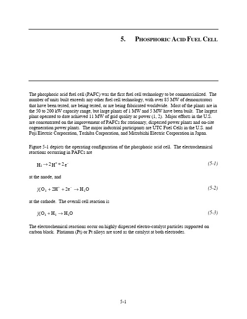
5. P HOSPHORIC A CID F UEL C ELLThe phosphoric acid fuel cell (PAFC) was the first fuel cell technology to be commercialized. The number of units built exceeds any other fuel cell technology, with over 85 MW of demonstrators that have been tested, are being tested, or are being fabricated worldwide. Most of the plants are in the 50 to 200 kW capacity range, but large plants of 1 MW and 5 MW have been built. The largest plant operated to date achieved 11 MW of grid quality ac power (1, 2). Major efforts in the U.S. are concentrated on the improvement of PAFCs for stationary, dispersed power plants and on-site cogeneration power plants. The major industrial participants are UTC Fuel Cells in the U.S. and Fuji Electric Corporation, Toshiba Corporation, and Mitsubishi Electric Corporation in Japan.Figure 5-1 depicts the operating configuration of the phosphoric acid cell. The electrochemical reactions occurring in PAFCs aree 2 + H 2 H +2−→(5-1)at the anode, andO H 2e 2H O 2221→++−+ (5-2)at the cathode. The overall cell reaction isO H H O 22221→+ (5-3)The electrochemical reactions occur on highly dispersed electro-catalyst particles supported on carbon black. Platinum (Pt) or Pt alloys are used as the catalyst at both electrodes.HydrogenFlowField Air (oxygen)Flow Field Waterand AirCathodeCurrentCollectorAnodeCurrentCollector AnodeBacking MEAHydrogenOutlet Cathode Backing e -e -ElectronsProtonsFigure 5-1 Principles of Operation of Phosphoric Acid Fuel Cell (Courtesy of UTC Fuel Cells)5.1Cell Components5.1.1 State-of-the-Art ComponentsThere have been only minor changes in cell design in recent years. The major U.S. manufacturer, UTC Fuel Cells, has concentrated on improving cell stability and life, and in improving the reliability of system components at reduced cost.The evolution of cell components from 1965 to the present day for PAFCs is summarized in Table 5-1. In the mid-1960s, the conventional porous electrodes were polytetrafluoroethylene (PTFE) - bonded Pt black, and the loadings were about 9 mg Pt/cm 2. During the past two decades, Pt supported on carbon black has replaced Pt black in porous PTFE-bonded electrode structures as the electro-catalyst. A dramatic reduction in Pt loading has also occurred; the loadings 13 are currently about 0.10 mg Pt/cm 2 in the anode and about 0.50 mg Pt/cm 2 in the cathode.The operating temperatures and acid concentrations of PAFCs have increased to achieve higher cell performance; temperatures of about 200 °C (392 °F) and acid concentrations of 100 percent H 3PO 4 are commonly used today. Although the present practice is to operate at atmospheric pressure, the operating pressure of PAFCs surpassed 8 atm in the 11 MW electric utilitydemonstration plant, confirming an increase in power plant efficiency. However, a number of 13. Assuming a cell voltage of 750 mV at 205 mA/cm 2 (approximate 11 MW design, 8 atmospheres) and the current Pt loadings at the anode and cathode, ~54 g Pt is required per kilowatt of power generated.issues remain whether to design and operate PAFC units at atmospheric vs. pressurized conditions.Primarily, small, multi-kW PAFC power units that were the focus of initial commercial applications led to atmospheric pressure operation. Although pressurization increased efficiency (lower fuel cost), it complicated the power unit - resulting in higher capital cost. The economic trade-off favored simpler, atmospheric operation for early commercial units.Another important issue, independent of power unit size, is that pressure promotes corrosion. Phosphoric acid electrolyte (H3PO4) produces a vapor. This vapor, which forms over the electrolyte, is corrosive to cell locations other than the active cell area. These cell locations are at a mixed voltage (open circuit and cell voltage), that can be over ~0.8V/cell. That is the limit above which corrosion occurs (active area limited to operation under ~0.8 V/cell). An increase in cell total pressure causes the partial pressure of the H3PO4 vapor to increase, causing increased corrosion in the cell. Cell temperature must also be increased with pressurized conditions to produce steam for the steam reformer (3).A major breakthrough in PAFC technology that occurred in the late 1960s was the development of carbon black and graphite for cell construction materials; this and other developments are reviewed by Appleby (4) and Kordesch (5). Carbon black and graphite were sufficiently stable to replace the more expensive gold-plated tantalum cell hardware used at the time. The use of high-surface-area graphite to support Pt permitted a dramatic reduction in Pt loading without sacrificing electrode performance. It was reported (4) that "without graphite, a reasonably inexpensive acid fuel cell would be impossible, since no other material combines the necessary properties of electronic conductivity, good corrosion resistance, low density, surface properties (especially in high area form) and, above all, low cost." However, carbon corrosion and Pt dissolution become an issue at cell voltages above ~0.8 V. Consequently, low current densities at cell voltage above 0.8 V and hot idle at open circuit potential should be avoided.The porous electrodes used in PAFCs have been described extensively in patent literature (6); see also the review by Kordesch (5). These electrodes contain a mixture of electro-catalyst supported on carbon black and a polymeric binder, usually PTFE (30 to 50 wt percent). The PTFE binds the carbon black particles together to form an integral, but porous, structure that is supported on a porous graphite substrate. The graphite structure serves as a support for the electro-catalyst layer, as well as the current collector. A typical graphite structure used in PAFCs has an initial porosity of about 90 percent, which is reduced to about 60 percent by impregnation with 40 wt percent PTFE. This wet-proof graphite structure contains macropores of 3 to 50 µm diameter (median pore diameter of about 12.5 µm) and micropores with a median pore diameter of about 34 Å for gas permeability. The composite structure, consisting of a carbon black/PTFE layer on the graphite substrate, forms a stable, three-phase interface in the fuel cell, with H3PO4 electrolyte on one side (electro-catalyst side) and the reactant gas environment on the other.Table 5-1 Evolution of Cell Component Technology for Phosphoric Acid Fuel CellsComponent ca. 1965 ca. 1975 Current Status a Anode PTFE-bonded Pt black PTFE-bonded Pt/C PTFE-bonded Pt/CXC-72aVulcan9 mg/cm20.25 mg Pt/cm20.25 mg Pt/cm2 Cathode PTFE-bonded Pt black PTFE-bonded Pt/C PTFE-bonded Pt/CXC-72aVulcan9 mg/cm20.5 mg Pt/cm20.5 mg Pt/cm2Ta mesh screen Graphite Structure Graphite Structure ElectrodeSupportGlass fiber paper PTFE-bonded SiC PTFE-bonded SiC ElectrolyteSupportElectrolyte 85 percent H3PO495 percent H3PO4100 percent H3PO4Porous graphite plate. Porous graphite plate. ElectrolyteReservoirCooler 1 per ~7 cells;imbedded (SS) tubesin graphite platea. - Over 40,000 hour component life demonstrated in commercial power plants.A bipolar plate separates the individual cells and electrically connects them in series in a fuel cell stack. In some designs, the bipolar plate also contains gas channels that feed the reactant gases to the porous electrodes and remove the reaction products and inerts. Bipolar plates made from graphite resin mixtures that are carbonized at low temperature (~900 °C/1,652 °F) are not suitable because of their rapid degradation in PAFC operating environments (7, 8). However, corrosion stability is improved by heat treatment to 2,700 °C (4,892 °F) (8), i.e., the corrosion current is reduced by two orders of magnitude at 0.8 V in 97 percent H3PO4 at 190°C (374 °F) and 4.8 atm (70.5 psi). The all-graphite bipolar plates are sufficiently corrosion-resistant for a projected life of 40,000 hours in PAFCs, but they are still relatively costly to produce.Several designs for the bipolar plate and ancillary stack components are used by fuel cell developers, and these are described in detail (9, 10, 11, 12). A typical PAFC stack contains cells connected in series to obtain the practical voltage level desired for the load. In such an arrangement, individual cells are stacked with bipolar plates between the cells. The bipolar plates used in early PAFCs consisted of a single piece of graphite with gas channels machined on either side to direct the flow of fuel and oxidant. Currently, both bipolar plates of the previous design and new designs consisting of several components are being considered. In the multi-component bipolar plates, a thin impervious plate separates the reactant gases in adjacent cells in the stack, andseparate porous plates with ribbed channels are used to direct gas flow. In a cell stack, the impervious plate is subdivided into two parts, and each joins one of the porous plates. The electrolyte vaporizes so that a portion of H3PO4 escapes from the cell in the air stream over time. An electrolyte reservoir plate (ERP), made of porous graphite, provides enough electrolyte to achieve a 40,000-hour cell life goal (there is no electrolyte replacement). The ERP also accommodates increases in electrolyte volume due to an increase in H2O, so the porous graphite electrodes don’t flood. These fluctuations in electrolyte volume occur during start-up and during transient operation. The porous structure, which allows rapid gas transport, is also used to store additional acid to replenish the supply lost by evaporation during the cell operating life.In PAFC stacks, provisions must be included to remove heat generated during cell operation. In practice, heat has been removed by either liquid (two-phase water or a dielectric fluid) or gas (air) coolants that are routed through cooling channels located (usually about every fifth cell) in the cell stack. Liquid cooling requires complex manifolds and connections, but better heat removal is achieved than with air-cooling. The advantage of gas cooling is its simplicity, reliability, and relatively low cost. However, the size of the cell is limited, and the air-cooling passages must be much larger than the liquid- cooling passages.Improvements in state-of-the-art phosphoric acid cells are illustrated by Figure 5-2. Performance by the ~1 m2 (10 ft2) short stack, (f), results in a power density of nearly 0.31 W/cm2.Figure 5-2 Improvement in the Performance of H2-Rich Fuel/Air PAFCsa - 1977: 190 °C, 3 atm, Pt loading of 0.75 mg/cm2 on each electrode (13)b - 1981: 190 °C, 3.4 atm, cathode Pt loading of 0.5 mg/cm2 (14)c - 1981: 205 °C, 6.3 atm, cathode Pt loading of 0.5 mg/cm2 (14)d - 1984: 205 °C, 8 atm, electro-catalyst loading was not specified (15)e - 1992: 205 °C, 8 atm, 10 ft2 short stack, 200 hrs, electro-catalyst loading not specified (16)f - 1992: 205 °C, 8 atm, subscale cells, electro-catalyst loading not specified (16)5.1.2Development ComponentsPhosphoric acid electrode/electrolyte technology has reached a level of maturity at which developers commit resources for commercial capacity, multi-unit demonstrations and pre-prototype installations. UTC Fuel Cells has 25 (200 kW) atmospheric pressure power plants that have operated between 30,000 to 40,000 hours. Most cell parts are graphite, and there has been no electrolyte replacement over the cell life of 40,000 hours. Grid-independent units undergo extensive cycling. Cell components are manufactured at scale and in large quantities, demonstrating confidence that predicted performance will be met (3). However, further increases in power density and reduced cost are needed to achieve economic competitiveness with other energy technologies, as expressed in the early 1990s (17, 18). Fuel cell developers continue to address these issues.In 1992, UTC Fuel Cells' predecessor, International Fuel Cells, completed a government-sponsored, advanced water-cooled PAFC development project to improve the performance andreduce the cost of both its atmospheric and pressurized technology for both on-site and utilityapplications (16). The project focused on five major activities: 1) produce a conceptual design of a large stack with a goal of 175 W/ft2 (0.188 W/cm2), 40,000 hour useful life, and a stack cost of less than $400/kW; 2) test pressurized Configuration "B" single cells developed in a previous program, but improved with proprietary design advances in substrates, electrolyte reservoir plates, catalysts, seals, and electrolyte matrix to demonstrate the 175 W/ft2 (0.188 W/cm2) power density goal; 3) test a pressurized short stack with subscale size, improved component cells, and additional improvements in the integral separators and coolers to confirm the stack design; 4) test a pressurized short stack of improved full-size cell components, nominal 10 ft2 size (approximately 1 m2), to demonstrate the 175 W/ft2 (0.188 W/cm2) power density goal, and 5) test an advanced atmospheric "on-site" power unit stack with the improved components.A conceptual design of an improved technology stack, operating at 120 psi (8.2 atm) and 405 °F (207 °C), was produced based on cell and stack development tests. The stack was designed for 355 10 ft2 (approximately 1 m2) cells to produce over 1 MW dc power in the same physical envelope as the 670 kW stack used in the 11 MW PAFC plant built for Tokyo Electric Power. The improvements made to the design were tested in single cells and in subscale and full size short stacks.Table 5-2 summarizes the results. Single cells achieved an initial performance of 0.75 volts/cell at a current density of 400 A/ft2 (431 mA/cm2) at 8.2 atm and 207 °C. The power density,300 W/ft2 (0.323 W/cm2), was well above the project goal. Several cells were operated to600 A/ft2 (645 mA/cm2), achieving up to 0.66 volts/cell. The flat plate component designs were verified in a subscale stack prior to fabricating the full size short stack. The pressurized short stack of 10 ft2 cells achieved a performance of 285 W/ft2 (0.307 W/cm2). Although the average cell performance, 0.71 volts/cell at 400 A/ft2 (431 mA/cm2), was not as high as the single cell tests, the performance was 65 percent higher than the project goal. Figure 5-3 presents single cell and stack performance data for pressurized operation. The stack was tested for over3,000 hours. For reference purposes, Tokyo Electric Power Company's 11 MW power plant, operational in 1991, had an average cell performance of approximately 0.75 volts/cell at190 mA/cm2 or 0.142 W/cm2 (19).Table 5-2 Advanced PAFC PerformanceAverage Cell Voltage, VCurrent Density mA/cm 2 Power Density W/cm 2 IFC Pressurized:Project GoalSingle CellsFull Size Short Stack11 MW Reference0.75 to 0.66 0.71 0.75 431 to 645 431 190 0.188 0.323 0.307 0.142 IFC Atmospheric:Single CellsFull Size Short Stack0.75 0.65 242 215 0.182 0.139 Mitsubishi Electric AtmosphericSingle Cells 0.65 300 0.195Figure 5-3 Advanced Water-Cooled PAFC Performance (16)The atmospheric pressure short stack, consisting of 32 cells, obtained an initial performance of 0.65 volts/cell at 200 A/ft 2 (215 mA/cm 2) or 0.139 W/cm 2. The performance degradation rate was less than 4 mV/1,000 hours during the 4,500 hour test. Single cells, tested at atmospheric conditions, achieved a 500 hour performance of approximately 0.75 volts/cell at 225 A/ft 2 (242 mA/cm 2) or 0.182 W/cm 2.Mitsubishi Electric Corporation investigated alloyed catalysts, processes to produce thinnerelectrolytes, and increased utilization of the catalyst layer (20). These improvements resulted in an initial atmospheric performance of 0.65 mV at 300 mA/cm 2 or 0.195 W/cm 2, which was higher than the UTC Fuel Cells' performance mentioned above (presented in Table 5-2 for comparison). Note that this performance was obtained using small 100 cm 2 cells and may not yet have beendemonstrated with full-scale cells in stacks. Approaches to increase life are to use series fuel gasflow in the stack to alleviate corrosion, provide well-balanced micropore size reservoirs to avoidelectrolyte flooding, and use a high corrosion resistant carbon support for the cathode catalyst.These improvements resulted in the lowest PAFC degradation rate publicly acknowledged:2 mV/1,000 hours for 10,000 hours at 200 to 250 mA/cm2 in a short stack with 3,600 cm2 areacells. UTC Fuel Cells reported a similar degradation rate in 2002 for power units operating up to40,000 hours (3).Several important technology development efforts for which details have been published includecatalyst improvements, advanced gas diffusion electrode development, and tests on materials thatoffer better carbon corrosion protection. Transition metal (e.g., iron, cobalt) organic macrocycles14from the families of tetramethoxyphenylporphyrins (TMPP), phthalocyanines (PC),tetraazaannulenes (TAA) and tetraphenylporphyrins (TPP) have been evaluated as O2-reductionelectro-catalysts in PAFCs. One major problem with these organic macrocycles is their limitedchemical stability in hot concentrated phosphoric acid. However, after heat treatment of theorganic macrocycle (i.e., CoTAA, CoPC, CoTMPP, FePC, FeTMPP) on carbon at about 500 to 800 °C (932 to1,472 °F), the pyrolyzed residue exhibits electro-catalytic activity that, in some instances, is comparable to that of Pt and has promising stability, at least up to about 100 °C/212 °F (21). Another successful approach for enhancing the electro-catalysis of O2 reduction is to alloy Pt with transition metals such as Ti (22), Cr (23), V (24), Zr, and Ta (24). The enhancement inelectro-catalytic activity has been explained by a correlation between the optimumnearest-neighbor distance of the elements in the alloy and the bond length in O2 (25). Conventional cathode catalysts comprise either platinum or platinum alloys supported on conducting carbon black at 10 wt percent platinum. Present platinum loadings on the anode and cathode are 0.1 mg/cm2 and 0.5 mg/cm2, respectively (12, 16). It has been suggested by Ito, et al., that the amount of platinum may have been reduced to the extent that it might be cost effective to increase the amount of platinum loading on the cathode (26). However, a problem exists in that fuel cell stack developers have not experienced satisfactory performance improvements when increasing the platinum loading. Johnson Matthey Technology Centre (J-M) presented data that resulted in improved performance nearly in direct proportion to that expected based on the increase in platinum (27). Initial tests by J-M confirmed previous results - that using platinum alloy catalyst with a 10 wt percent net platinum loading improves performance. Platinum/nickel alloy catalysts yielded a 49 wt percent increase in specific activity over pure platinum. This translated into a39 mV improvement in the air electrode performance at 200 mA/cm2.Johnson Matthey then determined that the platinum loading in the alloyed catalyst could beincreased up to 30 wt percent while retaining the same amount of platinum without any decrease inspecific activity or performance; the amount of nickel, hence the total amount of alloyed catalyst,decreased. Next, J-M researchers increased the amount of platinum from 10 to 30 wt percent whilekeeping the same nickel catalyst loading. The total amount of alloyed catalyst increased in thiscase. Results showed an additional 36 wt percent increase in specific activity, which providedanother 41 mV increase at 200 mA/cm2. The ideal voltage increase would have been 46 mV forthis increase in platinum. Thus, the performance increase obtained experimentally was nearly in 14. See Reference 21 for literature survey.direct proportion to the theoretical amount expected. The type of carbon support did not seem tobe a major factor, based on using several typical supports during the tests.The anode of a phosphoric acid fuel cell is subject to a reduction in performance when even lowamounts of contaminants are preferentially absorbed on the noble catalysts. Yet, hydrogen-richfuel gases, other than pure hydrogen, are produced with contaminant levels well in excess of theanode's tolerance limit. Of particular concern are CO, COS, and H2S in the fuel gas. The fuel stream in a state-of-the-art PAFC anode, operating at approximately 200 °C (392 °F), must contain 1 vol percent or less of CO (12), less than 50 ppmv of COS plus H2S, and less than 20 ppmv ofH2S (28). Current practice is to place COS and H2S cleanup systems and CO shift converters priorto the cell (normally in the fuel processor before reforming) to reduce the fuel stream contaminantlevels to the required amounts. Giner, Inc. performed experiments to develop a contaminant-tolerant anode catalyst in order to reduce or eliminate the cleanup equipment (29). An anodecatalyst, G87A-17-2, was identified that resulted in only a 24 mV loss from reference when exposed to a 75 percent H2, 1 percent CO, 24 percent CO2, 80 ppm H2S gas mixture at 190 °C (374 °F), 85 percent fuel utilization, and 200 mA/cm2. A baseline anode experienced a 36 mV loss from the reference at the same conditions. At 9.2 atm (120 psi) pressure, the anode loss was only 19 mV at 190 °C (374 °F) and 17 mV at 210 °C (410 °F) (compared with pure H2) with a gas of 71percent H2, 5 percent CO, 24 percent CO2, and 200 ppm H2S. Economic studies comparing thetradeoff between decreased cell performance with increased savings in plant cost showed noadvantage when the new anode catalyst was used with gas containing 1 percent CO/200 ppm H2S.A $7/kW increase resulted with the 5 percent CO gas (compared to a 1 percent CO gas) at a50 MW size. Some savings would result by eliminating the low temperature shift converter. Thereal value of the catalyst may be its ability to tolerate excessive CO and H2S concentrations duringfuel processor upsets, and to simplify the system by eliminating equipment.As previously mentioned, state-of-the-art gas diffusion electrodes are configured to provide anelectrolyte network and a gas network formed with the mixture of carbon black and PTFE. In the electrodes, carbon black agglomerates, consisting of small primary particles 0.02 to 0.04 µm, are mixed with much larger PTFE particles of ~0.3 µm. The carbon black surface may not be covered completely by the PTFE because of the large size of conventional PTFE particles. The space in the agglomerates or the space between the agglomerates and PTFE may act as gas networks at the initial stage of operation, but fill with electrolyte eventually because of the small contact angle of carbon black, uncovered with PTFE, to electrolyte (<90°), resulting in the degradation of cell performance. Attempts to solve this flooding problem by increasing the PTFE content have not been successful because of the offset in performance resulting from the reduction of catalyst utilization. Higher performance and longer lifetime of electrodes are intrinsically at odds, and there is a limit to the improvement in performance over life by optimizing PTFE content in the state-of-the-art electrode structures. Watanabe, et al. (30) proposed preparing an electrode utilizing 100 percent of catalyst clusters, where the functions of gas diffusion electrodes were allotted completely to a hydrophilic, catalyzed carbon black and a wet-proofed carbon black. The former worked as a fine electrolyte network, and the latter worked as a gas-supplying network in a reaction layer. Higher utilization of catalyst clusters and longer life at the reaction layer were expected, compared to state-of-the-art electrodes consisting of the uniform mixture of catalyzed carbon black and PTFE particles. The iR-free electrode potentials for the reduction of oxygen andair at 200 mA/cm2 on the advanced electrode were 10 mV higher than those of the conventional electrode.There is a trade-off between high power density and cell life performance. One of the major causes of declining cell performance over its life is that electrode flooding and drying, caused by migration of phosphoric acid between the matrix and the electrodes, occurs during cell load cycling. Researchers at Fuji Electric addressed two approaches to improve cell life performance while keeping power density high (31). In one, the wettability of the cathode and anode were optimized, and in the other a heat treatment was applied to the carbon support for the cathode catalyst. During tests, it was observed that a cell with low cathode wettability and high anode wettability was more than 50 mV higher than a cell with the reverse wetting conditions after 40 start/stop cycles.The use of carbon black with large surface area to improve platinum dispersion on supports was investigated as a method to increase the power density of a cell (32). However, some large surface area carbon blacks are fairly corrosive in hot potassium acid, resulting in a loss of catalytic activity. The corrosivity of the carbon support affects both the rate of catalyst loss and electrode flooding and, in turn, the life performance of a cell. Furnace black has been heat treated at high temperature by Fuji Electric to increase its resistance to corrosion. It was found that corrosion could be reduced and cell life performance improved by heat treating carbon supports at high temperature, at least to around 3,000 °C (5,432 °F).More recently, UTC Fuel Cells cites improvements to achieve 40,000 hour cell life through better cell temperature control, increasing H3PO4 inventory, and incorporating electrolyte reservoir plates in the cell stack (3).5.2PerformanceThere have been only minor changes in documented cell performance since the mid-1980s - mostly due to the operating conditions of the cell. The changes are reported in performance trends shown in this section that were primarily gained from contracts that UTC Fuel Cells had with the Department of Energy or outside institutions. New, proprietary PAFC performance data may likely have been observed by the manufacturer (3).Cell performance for any fuel cell is a function of pressure, temperature, reactant gas composition, and fuel utilization. In addition, performance can be adversely affected by impurities in both the fuel and oxidant gases.The sources of polarization in PAFCs (with cathode and anode Pt loadings of 0.5 mg Pt/cm2, 180 °C, 1 atm, 100 percent H3PO4) were discussed in Section 2 and were illustrated as half cell performance in Figure 2-4. From Figure 2-4 it is clear that the major polarization occurs at the cathode, and furthermore, the polarization is greater with air (560 mV at 300 mA/cm2) than with pure oxygen (480 mV at 300 mA/cm2) because of dilution of the reactant. The anode exhibits very low polarization (-4 mV/100 mA/cm2) on pure H2, and increases when CO is present in the fuel gas. The ohmic (iR) loss in PAFCs is also relatively small, amounting to about 12 mV at 100mA/cm2.Typical PAFCs will generally operate in the range of 100 to 400 mA/cm 2 at 600 to 800 mV/cell. Voltage and power constraints arise from increased corrosion of platinum and carbon components at cell potentials above approximately 800 mV.5.2.1 Effect of PressureEven though pressure operation is not being pursued, it is still of interest for possible future development. It is well known that an increase in the cell operating pressure enhances the performance of PAFCs (11, 33, 34). The theoretical change in voltage (∆V P ) as a function of pressure (P) is expressed as2P 1(3)(2.3RT)P (mV) = log V 2P ∆F (5-4)where 3(2.3)1382RT mV =F at 190°C (374 °F). Experimental data (35) reported that the effect of pressure on cell performance at 190°C (374 °F) and 323 mA/cm 2 is correlated by the equation:2P 1P (mV) = 146 log V P ∆ (5-5)where P 1 and P 2 are different cell pressures. The experimental data (35) also suggest that Equation (5-5) is a reasonable approximation for a temperature range of 177 °C < T < 218 °C (351 °F < T < 424 °F) and a pressure range of 1 atm < P < 10 atm (14.7 psi < P < 147.0 psi). Data from Appleby (14) in Figure 5-2 indicate that the voltage gain observed by increasing the pressure from3.4 atm (190 °C) to 6.3 atm (205 °C) is about 44 mV. According to Equation (5-5), the voltage gain calculated for this increase in pressure at 190 °C (374 °F) is 39 mV 15, which is in reasonable agreement with experimental data in Figure 5-2. Measurements (33) of ∆V P for an increase in pressure from4.7 to 9.2 atm (69.1 to 135.2 psia) in a cell at 190 °C (374 °F) show that ∆V P is a function of current density, increasing from 35 mV at 100 mA/cm 2 to 42 mV at 400 mA/cm 2 (50 percent O 2 utilization with air oxidant, 85 percent H 2 utilization with pure H 2 fuel). From Equation (5-4), ∆V p is 43 mV for an increase in pressure from 4.7 to 9.2 atm (69.1 to 135.2 psia) at 190 °C (374 °F), which is very close to the experimental value obtained at 400 mA/cm 2. Other measurements (36) for the same increase in pressure from 4.7 to 9.2 atm (69.1 to 135.2 psia), but at a temperature of 210 °C (410 °F) show less agreement between the experimental data and Equation (5-4).The improvement in cell performance at higher pressure and high current density can be attributed to a lower diffusion polarization at the cathode and an increase in the reversible cell potential. In addition, pressurization decreases activation polarization at the cathode because of the increased oxygen and water partial pressures. If the partial pressure of water is allowed to increase, a lower acid concentration will result. This will increase ionic conductivity and bring about a higher exchange current density. The net outcome is a reduction in ohmic losses. It was reported (33) that an increase in cell pressure (100 percent H 3PO 4, 169 °C (336 °F)) from 1 to 4.4 atm (14.7 to15. The difference in temperature between 190 and 205 °C is disregarded so Equation (5-5) is assumed to be valid at both temperatures.。
ARC WHITE PAPER 横河电机发布 VigilantPlant 说明书
ARC WHITE PAPERBy ARC Advisory GroupJ ANUARY 2005横河电机发布VigilantPlant概述 (3)VigilantPlant是在Vigilance信息基础上取得的进步 (4)VigilantPlant的开放、高可靠性的网络平台 (7)VigilantPlant的高度安全解决方案 (9)VigilantPlant的报警管理战略 (14)VigilantPlant的生产管理和最优化战略 (17)VigilantPlant实现资产管理OpX的途径 (18)VigilantPlant的优势和课题 (22)ARC White Paper • January 2005The Three Primary Components of VigilantPlant: Visibility, Predictability,and ActionVigilantPlant Brings Together Yokogawa’s Diverse Applications and Domain Expertise to form a Unified Approach to Knowledge ManagementARC White Paper • January 2005VigilantPlant 的本质就是一条可以依托横河电机的产品和能力,实现操作性能卓越化(Operational Excellence(OpX):通过卓越的操作能力展现经营上的优势)的途径。
VigilantPlant 的核心构成要素与OpX 模型非常吻合,即都是由“测量、控制、最佳化”这一改善循环组成的。
概述在经历了漫长的努力之后,横河电机开始向过程自动化行业传递出了明确的讯息。
该公司去年起开始举办大规模的国际化市场营销活动,向用户展示了其重视系统产品的可靠性、安全性、牢固性这一姿态。
此次命名为Vigilance 的营销活动,突出了横河电机的统一的形象,对于横河品牌和企业理念的渗透起到了重要作用。
FuelCellTechnologyHandbook:燃料电池技术手册
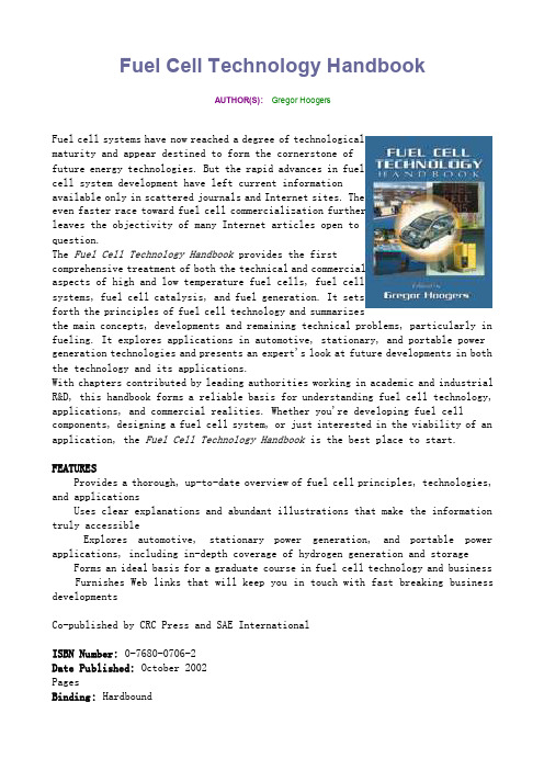
Fuel Cell Technology HandbookAUTHOR(S):Gregor HoogersFuel cell systems have now reached a degree of technologicalmaturity and appear destined to form the cornerstone offuture energy technologies. But the rapid advances in fuelcell system development have left current informationavailable only in scattered journals and Internet sites. Theeven faster race toward fuel cell commercialization furtherleaves the objectivity of many Internet articles open toquestion.The Fuel Cell Technology Handbook provides the firstcomprehensive treatment of both the technical and commercialaspects of high and low temperature fuel cells, fuel cellsystems, fuel cell catalysis, and fuel generation. It setsforth the principles of fuel cell technology and summarizesthe main concepts, developments and remaining technical problems, particularly in fueling. It explores applications in automotive, stationary, and portable power generation technologies and presents an expert's look at future developments in both the technology and its applications.With chapters contributed by leading authorities working in academic and industrial R&D, this handbook forms a reliable basis for understanding fuel cell technology, applications, and commercial realities. Whether you're developing fuel cell components, designing a fuel cell system, or just interested in the viability of an application, the Fuel Cell Technology Handbook is the best place to start.FEATURESProvides a thorough, up-to-date overview of fuel cell principles, technologies, and applicationsUses clear explanations and abundant illustrations that make the information truly accessibleExplores automotive, stationary power generation, and portable power applications, including in-depth coverage of hydrogen generation and storageForms an ideal basis for a graduate course in fuel cell technology and business Furnishes Web links that will keep you in touch with fast breaking business developmentsCo-published by CRC Press and SAE InternationalISBN Number: 0-7680-0706-2Date Published: October 2002PagesBinding: HardboundProduct Code: R-305 Product Status: In Stock。
顺磁氧表英文说明书

n Notes on Handling User’s Manuals
• Please hand over the user’s manuals to your end users so that they can keep the user’s manuals on hand for convenient reference. • Please read the information thoroughly before using the product. • The purpose of these user’s manuals is not to warrant that the product is well suited to any particular purpose but rather to describe the functional details of the product. • No part of the user’s manuals may be transferred or reproduced without prior written consent from YOKOGAWA. • YOKOGAWA reserves the right to make improvements in the user’s manuals and product at any time, without notice or obligation. • If you have any questions, or you find mistakes or omissions in the user’s manuals, please contact our sales representative or your local distributor.
燃料电池手册7_部分1

Fuel Cell Handbook(Seventh Edition)ByEG&G Technical Services, Inc. Under Contract No. DE-AM26-99FT40575 U.S. Department of EnergyOffice of Fossil Energy National Energy Technology LaboratoryP.O. Box 880 Morgantown, West Virginia 26507-0880November 2004D ISCLAIMERThis report was prepared as an account of work sponsored by an agency of the United States Government. Neither the United States Government nor any agency thereof, nor any of their employees, makes any warranty, express or implied, or assumes any legal liability or respon-sibility for the accuracy, completeness, or usefulness of any information, apparatus, product, or process disclosed, or represents that its use would not infringe privately owned rights. Reference herein to any specific commercial product, process, or service by trade name, trademark, manu-facturer, or otherwise does not necessarily constitute or imply its endorsement, recommendation, or favoring by the United States Government or any agency thereof. The views and opinions of authors expressed herein do not necessarily state or reflect those of the United States Govern-ment or any agency thereof.Available to DOE and DOE contractors from the Office of Scientific and Technical Information, P.O. Box 62, 175 Oak Ridge Turnpike, Oak Ridge, TN 37831; prices available at(423) 576-8401, fax: (423) 576-5725, E-mail: reports@Available to the public from the National Technical Information Service, U.S. Department of Commerce, 5285 Port Royal Road, Springfield, VA 22161; phone orders accepted at(703) 487-4650.。
燃料电池应用技术手册
燃料电池应用技术手册燃料电池(Fuel Cell)作为一种新兴的能源转换技术,具有高能量转换效率、清洁环保、低噪音等诸多优点,在诸多领域有着广泛的应用前景。
本手册将为读者提供关于燃料电池应用技术的详细介绍与实际操作指南。
第一章:燃料电池基础知识1.1 燃料电池的原理与分类本节将对燃料电池的基本原理进行解析,并介绍各种类型的燃料电池,包括质子交换膜燃料电池(PEMFC)、固体氧化物燃料电池(SOFC)等。
1.2 燃料电池组成与工作原理详细介绍燃料电池的组成结构,包括阳极、阴极、电解质等,并解释其工作原理和能量转换过程。
1.3 燃料电池的应用领域探讨燃料电池在交通运输、能源储备、航空航天等领域的广泛应用,并针对每个领域的需求特点进行分析。
第二章:燃料电池系统设计与优化2.1 燃料电池系统设计原则介绍燃料电池系统设计的基本原则,包括能量匹配、负载管理、热管理等,并提供系统设计的实用方法和技巧。
2.2 燃料电池堆叠与集成技术讲解燃料电池堆叠设计的要点,包括堆叠结构、气体循环、热平衡等,并介绍堆叠与其他系统组件的集成技术。
第三章:燃料电池关键材料3.1 阳极材料详细介绍用于燃料电池阳极的常见材料,如铂、钯合金等,并探讨材料的制备方法和改性技术。
3.2 阴极材料介绍用于燃料电池阴极的材料,如钴酸锂、铁酸锂等,并分析材料的储氢性能和循环稳定性。
3.3 电解质材料讨论燃料电池中常用的电解质材料,如聚四氟乙烯(PTFE)、磺酸聚合物等,并研究其导电性能和稳定性。
第四章:燃料电池性能评价与测试技术4.1 燃料电池性能评价指标介绍评价燃料电池性能的关键指标,如电压、功率密度、效率等,并提供相应的测试方法和实验操作指南。
4.2 燃料电池测试技术讲解燃料电池性能测试的常用技术,包括极化曲线测试、循环伏安测试等,并介绍测试中的注意事项和数据处理方法。
第五章:燃料电池应用案例5.1 汽车领域应用案例介绍燃料电池在汽车领域的应用案例,包括燃料电池乘用车、货运车辆等,并分析其优势和挑战。
横河模块(DIO)技术手册

横河模块(DIO)技术手册横河模块(DIO)技术手册1. 简介横河模块(DIO - Digital Input/Output)是一种用于控制和监测数字信号的设备,常用于工业自动化系统中。
本技术手册提供了关于横河模块的详细信息和使用说明。
2. 模块类型和规格2.1 模块类型横河模块(DIO)包括以下几种类型:输入模块、输出模块和输入/输出模块。
2.2 模块规格每种类型的横河模块(DIO)具有不同的规格和功能。
以下是常见的规格参数:- 输入模块:支持多个数字输入通道,每通道可以读取高或低电平信号。
- 输出模块:支持多个数字输出通道,可以发送高或低电平信号。
- 输入/输出模块:既可以读取数字输入信号,也可以发送数字输出信号。
3. 安装和连接3.1 安装将横河模块(DIO)安装在合适的位置,确保模块与其他设备之间有足够的空间。
3.2 连接将模块与其他设备连接,确保连接稳固可靠。
根据需要使用合适的电缆和接头。
4. 配置和编程4.1 配置在使用横河模块(DIO)之前,需要对其进行配置。
配置方式包括硬件设置和软件设置。
具体的配置方法请参考相应的用户手册。
4.2 编程横河模块(DIO)可以通过编程控制和监测数字信号。
根据所使用的编程语言,可以使用相应的库或API进行编程。
详细的编程说明和示例请参考相关的开发文档。
5. 故障排除在使用横河模块(DIO)时,可能会遇到各种故障。
以下是一些常见的故障及其排除方法:- 无法读取输入信号:检查输入信号的连接是否正确,确保输入通道有效。
- 无法发送输出信号:检查输出信号的连接是否正确,确保输出通道有效。
6. 附件本文档涉及的附件包括:- 横河模块(DIO)用户手册:提供了更多详细的使用说明和配置信息。
- 横河模块(DIO)开发文档:提供了编程接口和示例代码。
7. 法律名词及注释本文涉及的法律名词及其注释如下:- DIO: Digital Input/Output,数字输入/输出。
燃料电池简介ppt课件

2023-10-27
目录
• 燃料电池概述 • 燃料电池的特点 • 燃料电池的应用场景 • 燃料电池的发展现状与趋势 • 燃料电池的未来挑战与机遇 • 总结与展望
01
燃料电池概述
燃料电池的定义
燃料电池是一种将化学能直接转化为电能的发电装置。
它由正负极、电解质和外部电路组成,通过反应将燃料和氧化剂中的化学能转化 为电能。
要点一
固定电源
燃料电池可以作为一种可靠的固定电源,为家庭、商业 和工业用途提供电力。它们可以在断电或电力故障时提 供电力,并具有更高的能源效率和更低的维护成本。
要点二
分布式能源
燃料电池也可以作为一种分布式能源,为社区提供电力 。例如,一些城市已经开始使用燃料电池作为其分布式 能源的一部分,以减少对传统电网的依赖。
03
未来,燃料电池将成为一种重 要的能源转换方式,为人类的 生产生活提供更加清洁、高效 的能源解决方案。
05
燃料电池的未来挑战与机遇
技术挑战
01
02
03
材料问题
燃料电池的电解质、电 极和膜等关键材料仍需改 进,以提高其性能和稳定 性。
催化剂问题
在燃料电池中,催化剂 是促进反应的重要元素, 但目前催化剂的性能仍需 提升。
高效环保
总结词
燃料电池是一种高效和环保的能源转换技术。
详细描述
燃料电池通过将氢气和氧气结合产生电能和水蒸气,这个过程不会产生任何有害的排放物。此外,由于其高效 能量转换,燃料电池可以减少能源浪费,提高能源利用效率。
快速充电
总结词
燃料电池可以在短时间内完成充电。
详细描述
与传统的电池技术相比,燃料电池的充电速度更快。这是因为燃料电池的能量密度高,并且可以连续 供电,而不需要长时间的充电过程。
燃料电池手册7_部分2
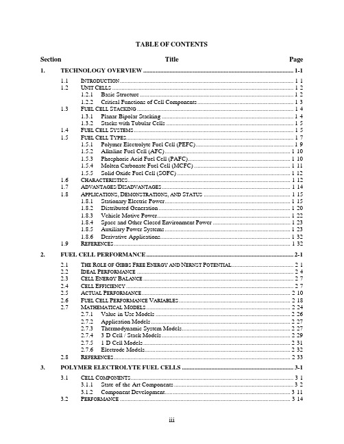
TABLE OF CONTENTSSection Title Page 1.TECHNOLOGY OVERVIEW.................................................................................................1-11.1I NTRODUCTION................................................................................................................1-11.2U NIT C ELLS.....................................................................................................................1-21.2.1Basic Structure...................................................................................................1-21.2.2Critical Functions of Cell Components..............................................................1-31.3F UEL C ELL S TACKING.....................................................................................................1-41.3.1Planar-Bipolar Stacking.....................................................................................1-41.3.2Stacks with Tubular Cells..................................................................................1-51.4F UEL C ELL S YSTEMS.......................................................................................................1-51.5F UEL C ELL T YPES............................................................................................................1-71.5.1Polymer Electrolyte Fuel Cell (PEFC)...............................................................1-91.5.2Alkaline Fuel Cell (AFC).................................................................................1-101.5.3Phosphoric Acid Fuel Cell (PAFC)..................................................................1-101.5.4Molten Carbonate Fuel Cell (MCFC)..............................................................1-111.5.5Solid Oxide Fuel Cell (SOFC).........................................................................1-121.6C HARACTERISTICS.........................................................................................................1-121.7A DVANTAGES/D ISADVANTAGES...................................................................................1-141.8A PPLICATIONS,D EMONSTRATIONS, AND S TATUS........................................................1-151.8.1Stationary Electric Power.................................................................................1-151.8.2Distributed Generation.....................................................................................1-201.8.3Vehicle Motive Power......................................................................................1-221.8.4Space and Other Closed Environment Power..................................................1-231.8.5Auxiliary Power Systems.................................................................................1-231.8.6Derivative Applications....................................................................................1-321.9R EFERENCES..................................................................................................................1-322.FUEL CELL PERFORMANCE...............................................................................................2-12.1T HE R OLE OF G IBBS F REE E NERGY AND N ERNST P OTENTIAL........................................2-12.2I DEAL P ERFORMANCE.....................................................................................................2-42.3C ELL E NERGY B ALANCE.................................................................................................2-72.4C ELL E FFICIENCY............................................................................................................2-72.5A CTUAL P ERFORMANCE................................................................................................2-102.6F UEL C ELL P ERFORMANCE V ARIABLES........................................................................2-182.7M ATHEMATICAL M ODELS.............................................................................................2-242.7.1Value-in-Use Models.......................................................................................2-262.7.2Application Models..........................................................................................2-272.7.3Thermodynamic System Models......................................................................2-272.7.43-D Cell / Stack Models...................................................................................2-292.7.51-D Cell Models...............................................................................................2-312.7.6Electrode Models..............................................................................................2-322.8R EFERENCES..................................................................................................................2-333.POLYMER ELECTROLYTE FUEL CELLS........................................................................3-13.1C ELL C OMPONENTS.........................................................................................................3-13.1.1State-of-the-Art Components.............................................................................3-23.1.2Component Development.................................................................................3-113.2P ERFORMANCE..............................................................................................................3-143.3PEFC S YSTEMS..............................................................................................................3-163.3.1Direct Hydrogen PEFC Systems......................................................................3-163.3.2Reformer-Based PEFC Systems.......................................................................3-173.3.3Direct Methanol Fuel Cell Systems.................................................................3-193.4PEFC A PPLICATIONS.....................................................................................................3-213.4.1Transportation Applications.............................................................................3-213.4.2Stationary Applications....................................................................................3-223.5R EFERENCES..................................................................................................................3-224.ALKALINE FUEL CELL.........................................................................................................4-14.1C ELL C OMPONENTS.........................................................................................................4-54.1.1State-of-the-Art Components.............................................................................4-54.1.2Development Components.................................................................................4-64.2P ERFORMANCE................................................................................................................4-74.2.1Effect of Pressure...............................................................................................4-84.2.2Effect of Temperature........................................................................................4-94.2.3Effect of Impurities..........................................................................................4-114.2.4Effects of Current Density................................................................................4-124.2.5Effects of Cell Life...........................................................................................4-144.3S UMMARY OF E QUATIONS FOR AFC.............................................................................4-144.4R EFERENCES..................................................................................................................4-165.PHOSPHORIC ACID FUEL CELL........................................................................................5-15.1C ELL C OMPONENTS.........................................................................................................5-25.1.1State-of-the-Art Components.............................................................................5-25.1.2Development Components.................................................................................5-65.2P ERFORMANCE..............................................................................................................5-115.2.1Effect of Pressure.............................................................................................5-125.2.2Effect of Temperature......................................................................................5-135.2.3Effect of Reactant Gas Composition and Utilization.......................................5-145.2.4Effect of Impurities..........................................................................................5-165.2.5Effects of Current Density................................................................................5-195.2.6Effects of Cell Life...........................................................................................5-205.3S UMMARY OF E QUATIONS FOR PAFC...........................................................................5-215.4R EFERENCES..................................................................................................................5-226.MOLTEN CARBONATE FUEL CELL..................................................................................6-16.1C ELL C OMPONENTS.........................................................................................................6-46.1.1State-of-the-Art Componments..........................................................................6-46.1.2Development Components.................................................................................6-96.2P ERFORMANCE..............................................................................................................6-136.2.1Effect of Pressure.............................................................................................6-156.2.2Effect of Temperature......................................................................................6-196.2.3Effect of Reactant Gas Composition and Utilization.......................................6-216.2.4Effect of Impurities..........................................................................................6-256.2.5Effects of Current Density................................................................................6-306.2.6Effects of Cell Life...........................................................................................6-306.2.7Internal Reforming...........................................................................................6-306.3S UMMARY OF E QUATIONS FOR MCFC..........................................................................6-346.4R EFERENCES..................................................................................................................6-387.SOLID OXIDE FUEL CELLS..................................................................................................7-17.1C ELL C OMPONENTS.........................................................................................................7-27.1.1Electrolyte Materials..........................................................................................7-27.1.2Anode Materials.................................................................................................7-37.1.3Cathode Materials..............................................................................................7-57.1.4Interconnect Materials........................................................................................7-67.1.5Seal Materials.....................................................................................................7-97.2C ELL AND S TACK D ESIGNS...........................................................................................7-137.2.1Tubular SOFC..................................................................................................7-137.2.1.1 Performance........................................................................................7-207.2.2Planar SOFC.....................................................................................................7-317.2.2.1 Single Cell Performance......................................................................7-357.2.2.2 Stack Performance...............................................................................7-397.2.3Stack Scale-Up.................................................................................................7-417.3S YSTEM C ONSIDERATIONS............................................................................................7-457.4R EFERENCES..................................................................................................................7-458.FUEL CELL SYSTEMS............................................................................................................8-18.1S YSTEM P ROCESSES........................................................................................................8-28.1.1Fuel Processing..................................................................................................8-28.2P OWER C ONDITIONING..................................................................................................8-278.2.1 Introduction to Fuel Cell Power Conditioning Systems...................................8-288.2.2 Fuel Cell Power Conversion for Supplying a Dedicated Load [2,3,4].............8-298.2.3 Fuel Cell Power Conversion for Supplying Backup Power to a LoadConnected to a Local Utility............................................................................8-348.2.4 Fuel Cell Power Conversion for Supplying a Load Operating in ParallelWith the Local Utility (Utility Interactive)......................................................8-378.2.5 Fuel Cell Power Conversion for Connecting Directly to the Local Utility......8-378.2.6 Power Conditioners for Automotive Fuel Cells...............................................8-398.2.7 Power Conversion Architecture for a Fuel Cell Turbine Hybrid InterfacedWith a Local Utility..........................................................................................8-418.2.8 Fuel Cell Ripple Current..................................................................................8-438.2.9 System Issues: Power Conversion Cost and Size.............................................8-44R EFERENCES (Sections 8.1 and 8.2).................................................................8-458.2.108.3S YSTEM O PTIMIZATION.................................................................................................8-468.3.1Pressure............................................................................................................8-468.3.2Temperature.....................................................................................................8-488.3.3Utilization.........................................................................................................8-498.3.4Heat Recovery..................................................................................................8-508.3.5Miscellaneous...................................................................................................8-518.3.6Concluding Remarks on System Optimization................................................8-518.4F UEL C ELL S YSTEM D ESIGNS........................................................................................8-528.4.1Natural Gas Fueled PEFC System...................................................................8-528.4.2Natural Gas Fueled PAFC System...................................................................8-538.4.3Natural Gas Fueled Internally Reformed MCFC System.................................8-568.4.4Natural Gas Fueled Pressurized SOFC System................................................8-588.4.5Natural Gas Fueled Multi-Stage Solid State Power Plant System...................8-628.4.6Coal Fueled SOFC System...............................................................................8-668.4.7Power Generation by Combined Fuel Cell and Gas Turbine System..............8-708.4.8Heat and Fuel Recovery Cycles.......................................................................8-708.5F UEL C ELL N ETWORKS.................................................................................................8-828.5.1Molten Carbonate Fuel Cell Networks: Principles, Analysis andPerformance.....................................................................................................8-828.5.2MCFC Network................................................................................................8-868.5.3Recycle Scheme...............................................................................................8-868.5.4Reactant Conditioning Between Stacks in Series.............................................8-868.5.5Higher Total Reactant Utilization....................................................................8-878.5.6Disadvantages of MCFC Networks..................................................................8-888.5.7Comparison of Performance.............................................................................8-888.5.8Conclusions......................................................................................................8-898.6H YBRIDS........................................................................................................................8-898.6.1Technology.......................................................................................................8-898.6.2Projects.............................................................................................................8-928.6.3World’s First Hybrid Project............................................................................8-938.6.4Hybrid Electric Vehicles (HEV)......................................................................8-938.7F UEL C ELL A UXILIARY P OWER S YSTEMS.....................................................................8-968.7.1System Performance Requirements..................................................................8-978.7.2Technology Status............................................................................................8-988.7.3System Configuration and Technology Issues.................................................8-998.7.4System Cost Considerations...........................................................................8-1028.7.5SOFC System Cost Structure.........................................................................8-1038.7.6Outlook and Conclusions...............................................................................8-1048.8R EFERENCES................................................................................................................8-1049.SAMPLE CALCULATIONS....................................................................................................9-19.1U NIT O PERATIONS...........................................................................................................9-19.1.1Fuel Cell Calculations........................................................................................9-19.1.2Fuel Processing Calculations...........................................................................9-139.1.3Power Conditioners..........................................................................................9-169.1.4Others...............................................................................................................9-169.2S YSTEM I SSUES..............................................................................................................9-169.2.1Efficiency Calculations....................................................................................9-179.2.2Thermodynamic Considerations.......................................................................9-199.3S UPPORTING C ALCULATIONS........................................................................................9-229.4C OST C ALCULATIONS....................................................................................................9-259.4.1Cost of Electricity.............................................................................................9-259.4.2Capital Cost Development...............................................................................9-269.5C OMMON C ONVERSION F ACTORS.................................................................................9-279.6A UTOMOTIVE D ESIGN C ALCULATIONS.........................................................................9-289.7R EFERENCES..................................................................................................................9-2910.APPENDIX...............................................................................................................................10-110.1E QUILIBRIUM C ONSTANTS............................................................................................10-110.2C ONTAMINANTS FROM C OAL G ASIFICATION................................................................10-210.3S ELECTED M AJOR F UEL C ELL R EFERENCES,1993 TO P RESENT...................................10-410.4L IST OF S YMBOLS........................................................................................................10-1010.5F UEL C ELL R ELATED C ODES AND S TANDARDS..........................................................10-1410.5.1Introduction....................................................................................................10-1410.5.2Organizations.................................................................................................10-1510.5.3Codes & Standards.........................................................................................10-1610.5.4Codes and Standards for Fuel Cell Manufacturers.........................................10-1710.5.5Codes and Standards for the Installation of Fuel Cells..................................10-1910.5.6Codes and Standards for Fuel Cell Vehicles..................................................10-1910.5.7Application Permits........................................................................................10-1910.5.8References......................................................................................................10-2110.6F UEL C ELL F IELD S ITE D ATA......................................................................................10-2110.6.1Worldwide Sites.............................................................................................10-2110.6.2DoD Field Sites..............................................................................................10-2410.6.3IFC Field Units...............................................................................................10-2410.6.4FuelCell Energy..............................................................................................10-2410.6.5Siemens Westinghouse...................................................................................10-2410.7H YDROGEN..................................................................................................................10-3110.7.1Introduction....................................................................................................10-3110.7.2Hydrogen Production.....................................................................................10-3210.7.3DOE’s Hydrogen Research............................................................................10-3410.7.4Hydrogen Storage...........................................................................................10-3510.7.5Barriers...........................................................................................................10-3610.8T HE O FFICE OF E NERGY E FFICIENCY AND R ENEWABLE E NERGY W ORK IN F UELC ELLS..........................................................................................................................10-3610.9R ARE E ARTH M INERALS.............................................................................................10-3810.9.1Introduction....................................................................................................10-3810.9.2Outlook...........................................................................................................10-4010.10R EFERENCES................................................................................................................10-4111.INDEX.......................................................................................................................................11-1LIST OF FIGURESFigure Title Page Figure 1-1 Schematic of an Individual Fuel Cell...................................................................1-2Figure 1-2 Expanded View of a Basic Fuel Cell Unit in a Fuel Cell Stack (1).....................1-4Figure 1-3 Fuel Cell Power Plant Major Processes................................................................1-7Figure 1-4 Relative Emissions of PAFC Fuel Cell Power Plants Compared to StringentLos Angeles Basin Requirements......................................................................1-13Figure 1-5 PC-25 Fuel Cell..................................................................................................1-16Figure 1-6 Combining the SOFC with a Gas Turbine Engine to Improve Efficiency........1-19Figure 1-7 Overview of Fuel Cell Activities Aimed at APU Applications.........................1-24Figure 1-8 Overview of APU Applications.........................................................................1-24Figure 1-9 Overview of typical system requirements..........................................................1-25Figure 1-10 Stage of development for fuel cells for APU applications................................1-26Figure 1-11 Overview of subsystems and components for SOFC and PEFC systems.........1-28Figure 1-12 Simplified process flow diagram of pre-reformer/SOFC system......................1-29Figure 1-13 Multilevel system modeling approach...............................................................1-30Figure 1-14 Projected Cost Structure of a 5kWnet APU SOFC System. .............................1-32Figure 2-1 H2/O2 Fuel Cell Ideal Potential as a Function of Temperature............................2-5Figure 2-2 Effect of fuel utilization on voltage efficiency and overall cell efficiencyfor typical SOFC operating conditions (800 °C, 50% initial hydrogenconcentration)....................................................................................................2-10Figure 2-3 Ideal and Actual Fuel Cell Voltage/Current Characteristic...............................2-11Figure 2-4 Example of a Tafel Plot.....................................................................................2-13Figure 2-5 Example of impedance spectrum of anode-supported SOFC operated at°C................................................................................................................2-14850Figure 2-6 Contribution to Polarization of Anode and Cathode..........................................2-17Figure 2-7 Voltage/Power Relationship..............................................................................2-19Figure 2-8 The Variation in the Reversible Cell Voltage as a Function of ReactantUtilization..........................................................................................................2-23Figure 2-9 Overview of Levels of Fuel Cell Models...........................................................2-26Figure 2-10 Conours of Current Density on Electrolyte.......................................................2-31Figure 2-11 Typical Phenomena Considered in a 1-D Model (17).......................................2-32Figure 2-12 Overview of types of electrode models (9)........................................................2-33Figure 3-1 (a) Schematic of Representative PEFC (b) Single Cell Structure ofPEFC...........................................................................................3-2RepresentativeFigure 3-2 PEFC Schematic (4, 5).........................................................................................3-3Figure 3-3 Polarization Curves for 3M 7 Layer MEA (12)...................................................3-7Figure 3-4 Endurance Test Results for Gore Primea 56 MEA at Three CurrentDensities.............................................................................................................3-10Figure 3-5 Multi-Cell Stack Performance on Dow Membrane (9)......................................3-12Figure 3-6 Effect on PEFC Performance of Bleeding Oxygen into the Anode(1)................................................................................................3-13CompartmentFigure 3-7 Evolutionary Changes in PEFCs Performance [(a) H2/O2, (b) H2/Air,(c) Reformate Fuel/Air, (d) H2/unkown)] [24, 10, 12, , ]..................................3-14。
燃料电池技术及应用

燃料电池技术及应用燃料电池是一种将化学能直接转化为电能的高效能源技术。
它通过将氢气与氧气在电化学反应中发生氧化还原反应,产生电能。
燃料电池技术具有高能量转换效率、零排放、低噪音等优点,被广泛应用于汽车、航空航天、电力等领域。
燃料电池的原理是利用纯氧气和燃料电解质反应产生电流,而且只有两种废物水和烟碱。
燃料电池由电极、电解质和阳极组成。
常见的燃料电池种类有质子交换膜燃料电池(PEMFC)、固体氧化物燃料电池(SOFC)和碱性燃料电池(AFC)等。
不同种类的燃料电池在结构、材料和工作条件等方面具有差异,但其工作原理基本相同。
燃料电池技术的应用非常广泛。
其中最为突出的是在汽车领域。
燃料电池车辆具有零排放、高能量转换效率的特点,可以有效缓解传统燃油车辆带来的环境污染问题。
目前,全球许多国家和地区已经开始大力推广燃料电池汽车,并制定了相应的政策和补贴措施。
同时,燃料电池技术在航空航天和电力等领域也有着广泛应用。
在一些特殊环境下,如航空航天领域的长途飞行任务、电力系统的备用电源等,燃料电池具有便携性、高效性等优势,成为了替代传统能源的重要选择。
燃料电池技术的发展还面临一些挑战。
目前,燃料电池技术的主要问题包括储氢、催化剂的稳定性、燃料电池系统的成本以及燃料电池堆的寿命等方面。
其中,储氢技术作为燃料电池技术的核心问题之一,一直是限制其广泛应用的瓶颈。
儿目前,研究者们正在积极寻找高效的储氢材料,以提高燃料电池的能量密度和储氢性能。
此外,催化剂的稳定性也是燃料电池技术发展的难点之一、目前,研究者们正在努力开发更加稳定的催化剂,以提高燃料电池的寿命和性能。
总的来说,燃料电池技术是一项非常有前景的能源技术。
随着对环境污染的关注不断增加,燃料电池技术将成为未来能源的重要选择。
通过持续的研发和创新,燃料电池技术有望进一步提高能量转换效率、降低成本、延长寿命,促进其在各个领域的广泛应用。
燃料电池及其应用

燃料电池及其应用
燃料电池是一种能够将化学能直接转化为电能的高效绿色能源。
它利用氢气和
氧气反应产生电能和水,其废气为二氧化碳。
相比传统化石燃料燃烧发电,燃料电池不产生有害气体,环保效益显著。
燃料电池的工作原理类似于电池,但与电池不同的是,燃料电池的电能来源于
氢气和氧气等气体在电催化剂作用下的化学反应。
燃料电池的结构包括排气系统、催化剂、电极、电解质层、集流板和电池管理系统等组成部分。
其中电极分为阳极和阴极,电解质层是氢离子的导体,在电池中的作用类似于电线。
燃料电池有多种类型,最常见的是质子交换膜燃料电池(PEMFC)和固体氧化物
燃料电池(SOFC)。
PEMFC使用质子交换膜作为电解质,工作温度相比其他类型低,具有快速启动、高效率、较小体积等优点,适用于小型家电、汽车等载体。
SOFC
使用固体氧化物作为电解质,工作环境温度比PEMFC高,但效率更高,适用于重
型电力站等大型能源系统中。
燃料电池的应用范围广泛,其中汽车领域是最重要的之一。
燃料电池汽车是指
使用燃料电池作为动力源的汽车,相比传统的汽油车、电动车等,它具有零气体排放、安静舒适、续航能力强等特点。
目前世界各大汽车制造商正在加紧研制燃料电池汽车,并在日本、韩国等国家陆续推出相关政策和补贴,推动燃料电池汽车产业化。
此外,燃料电池还广泛应用于航空航天、海洋工程、电力和微型电源等方面。
在未来的能源转型和环保常识中,燃料电池将成为愈发重要的一环。
燃料电池应用手册(横河)JAPAN解析
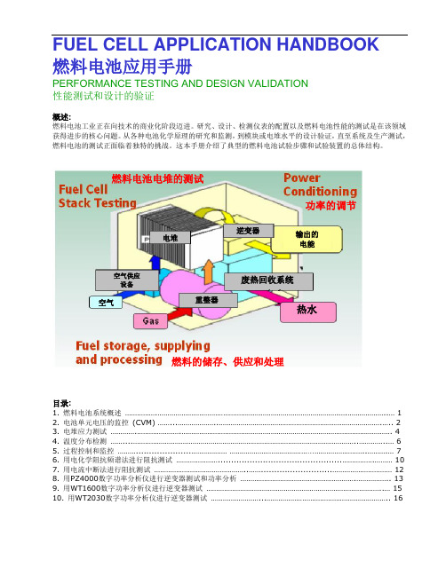
FUEL CELL APPLICATION HANDBOOK 燃料电池应用手册PERFORMANCE TESTING AND DESIGN VALIDATION 性能测试和设计的验证概述:燃料电池工业正在向技术的商业化阶段迈进。
研究、设计、检测仪表的配置以及燃料电池性能的测试是在该领域获得进步的核心问题。
从各种电池化学原理的研究和监测,到模块或电堆水平的设计验证,直至系统及生产测试,燃料电池的测试正面临着独特的挑战。
这本手册介绍了典型的燃料电池试验步骤和试验装置的总体结构。
目录:1. 燃料电池系统概述 ...................................................................................................................................... 1 2. 电池单元电压的监控 (CVM) .................................................................................................................... 2 3. 电堆应力测试 ............................................................................................................................................. 4 4. 温度分布检测 ............................................................................................................................................ 6 5. 过程控制和监控 ................................................ ................................................................................. 7 6. 用电化学阻抗频谱法进行阻抗测试 ............................................................................................. 10 7. 用电流中断法进行阻抗测试 .............................................................................................................. 12 8. 用PZ4000数字功率分析仪进行逆变器测试和功率分析 ........................................................................... 13 9. 用WT1600数字功率分析仪进行逆变器测试 ............................................................................................ 15 10. 用WT2030数字功率分析仪进行逆变器测试 .. (16)逆变器电堆重整器空气空气供应 设备废热回收系统输出的 电能热水燃料电池电堆的测试功率的调节燃料的储存、供应和处理应用:由于单一电池单元所产生的电压在0.8-1.5VDC 范围内, 必须将电池单元串联成电堆才能发出足够的电能。
燃料电池的应用场景以及示范工程。

燃料电池的应用场景以及示范工程。
下载提示:该文档是本店铺精心编制而成的,希望大家下载后,能够帮助大家解决实际问题。
文档下载后可定制修改,请根据实际需要进行调整和使用,谢谢!本店铺为大家提供各种类型的实用资料,如教育随笔、日记赏析、句子摘抄、古诗大全、经典美文、话题作文、工作总结、词语解析、文案摘录、其他资料等等,想了解不同资料格式和写法,敬请关注!Download tips: This document is carefully compiled by this editor. I hope that after you download it, it can help you solve practical problems. The document can be customized and modified after downloading, please adjust and use it according to actual needs, thank you! In addition, this shop provides you with various types of practical materials, such as educational essays, diary appreciation, sentence excerpts, ancient poems, classic articles, topic composition, work summary, word parsing, copy excerpts, other materials and so on, want to know different data formats and writing methods, please pay attention!燃料电池的应用场景与示范工程引言燃料电池作为一种清洁高效的能源转换技术,正在逐渐走向商业化和大规模应用。
- 1、下载文档前请自行甄别文档内容的完整性,平台不提供额外的编辑、内容补充、找答案等附加服务。
- 2、"仅部分预览"的文档,不可在线预览部分如存在完整性等问题,可反馈申请退款(可完整预览的文档不适用该条件!)。
- 3、如文档侵犯您的权益,请联系客服反馈,我们会尽快为您处理(人工客服工作时间:9:00-18:30)。
FUEL CELL APPLICATION HANDBOOK 燃料电池应用手册PERFORMANCE TESTING AND DESIGN VALIDATION 性能测试和设计的验证概述:燃料电池工业正在向技术的商业化阶段迈进。
研究、设计、检测仪表的配置以及燃料电池性能的测试是在该领域获得进步的核心问题。
从各种电池化学原理的研究和监测,到模块或电堆水平的设计验证,直至系统及生产测试,燃料电池的测试正面临着独特的挑战。
这本手册介绍了典型的燃料电池试验步骤和试验装置的总体结构。
目录:1. 燃料电池系统概述 ...................................................................................................................................... 1 2. 电池单元电压的监控 (CVM) .................................................................................................................... 2 3. 电堆应力测试 ............................................................................................................................................. 4 4. 温度分布检测 ............................................................................................................................................ 6 5. 过程控制和监控 ................................................ ................................................................................. 7 6. 用电化学阻抗频谱法进行阻抗测试 ............................................................................................. 10 7. 用电流中断法进行阻抗测试 .............................................................................................................. 12 8. 用PZ4000数字功率分析仪进行逆变器测试和功率分析 ........................................................................... 13 9. 用WT1600数字功率分析仪进行逆变器测试 ............................................................................................ 15 10. 用WT2030数字功率分析仪进行逆变器测试 .. (16)逆变器电堆重整器空气空气供应 设备废热回收系统输出的 电能热水燃料电池电堆的测试功率的调节燃料的储存、供应和处理应用:由于单一电池单元所产生的电压在0.8-1.5VDC 范围内, 必须将电池单元串联成电堆才能发出足够的电能。
一个典型的燃料电池电堆大约由100个燃料电池单元串联构成。
但是,通常不会制造600个电池单元串联的电堆,特别是在用于汽车的燃料电池电堆领域。
一个燃料电池单元电压监控仪(CVM )用于测量布置成电堆形式发电装置中的每一个电池单元的电压。
采用这种测量方法可以成电堆中识别出有问题的电池单元,对现场使用或带负荷运行的电堆进行电池单元长期运行特性的表征。
采用差分测量方法来测量每一个电池单元的电压。
电池单元本身的电压很低,对于仪器的内部地线,每个差分输入的引线脚上实际上可以测得数百伏特的电压。
这种情况被称为共模电压。
大多数数据采集系统(DAQ )没有进行隔离,因此输入电压受到限制,以免插卡被永久性地损坏,通常仅为5-10V 。
此外,非隔离的设备常常怀会受到接地回路的影响。
为了克服在燃料电池单元电压监控仪有可能遇到的共模电压高的困难,就需要一种高电压隔离栅。
由于内部的信号调理或缓冲器由第三方供应,目前许多数据采集系统(DAQ )带有外部缓冲器,这样不仅缩小了包装的空间和成本,还能够维持尽可能高的信号分辨率和精度。
解决的方法:与当今流行的任何固态器件数据采集系统相比,MX-100型数据采集仪能提供最高水平的通道-地线、模块-模块、通道-通道的隔离。
由于其采用了模块结构以及标准的软件,用MX-100就可以容易地监控成百上千个燃料电池单元的电压。
MX100 DAQMaster模块1模块(n/10)模块间最大隔离电压 Vmax =600Vrms/Vdc从地计Vmax =600Vrms/Vdc应用说明燃料电池单元的电压监控(CVM )解决方法:要使通道数高的数据采集系统达到高电压隔离的要求在设计上是一种挑战,因为,大多数数据采集模块只使用一个带多路转换开关或扫描前端器件的A-D ,因此,高共模电压的信号在由隔离变压器和A-D 转换器进行隔离和模数转换前,首先要通过开关继电器。
MX1400采用了一种申请了专利的 Yokogawa 固态继电器(SSR )技术,允许连续负载电压达到1500VDC 。
此外,MX-100配备的隔离变压器和A-D 转换器也采用申请有专利的Yokogawa 设计。
其它数据采集系统所提供的高电压隔离是采用电子—机械继电器,这种结构存在开关反跳、整定时间长和需要经常维护等问题。
总之,MX100数据采集仪提供了空前的隔离能力和操作特性,其标准模块带有可以同时采样的四个采样通道,各通道之间相互隔离。
燃料电池单元的电压监控(续)测量时闭合主控制 模块顺序 控制器 (ASIC)金属框架A/D 转换器A/D 转换器 250V(B)250V(B)250V(D)600V(D)600V(D)600V(D)600V(B)接地 机箱AI-H04模块应用:当采用相对简单的机械结构将燃料电池单元连接成电堆时,制造公差尺寸上的细微变化均会严重地影响到电堆的操作特性。
通常用螺栓来紧固和压紧电堆。
作用在每一个螺栓上的压力会影响到电堆的电化学过程,从而影响到电堆的电压输出。
为了对电堆的应力与电堆或电池单元的电压的关系进行测试和调节,首先需要对应力作定量的测定。
在机电一体化和消费类产品测试中广泛使用应力传感器。
它是一种韦斯顿电桥,可以是四臂、两臂或一臂为测量臂的形式。
在两臂或一臂为测量臂的应用场合,桥路的其它臂为高精度的电阻。
完整的四臂桥路需要电压激励。
此外,所测量的信号值通常仅为几个毫伏,所以为了能够高精度的显示应力的大小,需要对信号进行适当的放大和滤波。
解决的方法:WE7000是一种网络式、模块化的数据采集系统,能通过一台微机进行高精度的测量和控制。
采用WE7245应力计测量模块,系统就可以容易地检测或分析从四个通道至上百个通道的应力计的应力分布信号。
电堆应力分析衬垫和封装有效栅长末端回路 电阻栅定位标志末端回路焊接接点韦斯顿 电桥电路O/PO/PEE 测量桥路应变片传感器应力测定的特点:• 采样速度100 kS/sec, 同时对各通道进行采样(各通道有独立的A/D转换器),• 支持单一测量臂,双臂或四臂测量臂桥路设计,• 自动平衡和分支路校正,• 120 Ohm, 350 Ohm, 或定制的电桥测量头,• 激励电压: 各通道可以在2V, 5V 或10V之间选择。
• 各通道间完全隔离完全消除了接地回路和共模电压的影响,• 向PC发送连续的数据流,还可以选用每通道最高到一百万个采样值的模块寄存器。
• 内置消除噪声的硬件低通滤波器• 每个通道都可以重新设置成电压输入通道,而不仅仅是应力信号通道。
电堆应力分析(续)应用:不管采用何种燃料电池(质子交换膜燃料电池(PEM),固体氧化物燃料电池(SOFC)等),为了优化电堆的性能和避免过热,最为关键的是热能的和监控和管理。
因此温度的测量贯穿到整个燃料电池系统,从电堆本身的温度到所供气体的温度,还包括重整器、逆变器的温度,在某些情况下还可能包括联合发电的其它部件。
因此,所采用的热电偶或电阻温度传感器(RTD)的通道数常常会达到数百个。
所以,一种紧凑的、模块化的和可以重新设置的数据采集系统才是最为理想的测量工具。
此外,用热电偶测量燃料电池温度和逆变器输出的温度,和电池单元的电压监控(CVM)一样,也存在共模电压高的问题,为了避免仪器的损坏,同样也必须采取必要的预防措施。
对于燃料电池的测试而言,由于热电偶成本低廉和需要检测的通道数较多,通常选择热电偶,而不选择电阻温度传感器(RTD)。
同时应当说明,不同数据采集系统的热电偶测量误差可能不同,从± 0.5°C 到± 5°C 或更高。
解决的方法:MX100 DAQ Master数据采集系统适合于各种输入信号,是专门为各种分度号热电偶而设计的。
每个模块有10个通道,通过增加模块的数量可以很容易地达到将测量系统扩大到成百上千个通道,可以用一台PC通过以太网(Ethernet)监控所有的模块。
温度测量的特点:• 支持的热电偶分度号包括:R, S, B, K, E, J, T, L, U, N, W, KpvsAu7Fe,• 带冷端补偿,• 自动检测热电偶开路/烧毁,• 支持远程参考接点补偿(RJC),• 测量分辨率为0.1°C。
• RTD 测量时使用1mA 或2mA 激励电流,• 支持以下分度号的电阻温度检测器(RTD):Pt100, JPt100, Hi-res Pt100, Hi-res,JPt100, Ni100SAMA, Ni100DIN, Ni120, Pt50, Cu10GE, Cu10L&N, Cu10WEED, Cu10BAILEY, J263B电堆的温度分布测定应用:燃料电池测试站的核心部分就是一个过程控制和监测系统。
这些控制I/O 信集中送如一台PC 机,以这台PC 机为测试仪的主要用户界面。
