G170ETN02.0_Ver1.3_90%色域医疗首选工业液晶屏-杭州旭虹科技有限公司
航天数控2100etaG代码
航天数控2100etaG代码在学习数控编程中,首先我们要知道数控车床编程代码指令所代表的意思,才能灵活运用,今天给大家带来的是G代码和M 代码指令详解,如下:一、G代码功能简述G00------快速定位G01------直线插补G02------顺时针方向圆弧插补G03------逆时针方向圆弧插补G04------定时暂停G05------通过中间点圆弧插补G06------抛物线插补G07------Z 样条曲线插补G08------进给加速G09------进给减速G10------数据设置G16------极坐标编程G17------加工XY平面G18------加工XZ平面G19------加工YZ平面G20------英制尺寸G21-----公制尺寸G22------半径尺寸编程方式G220-----系统操作界面上使用G23------直径尺寸编程方式G230-----系统操作界面上使用G24------子程序结束G25------跳转加工G26------循环加工G30------倍率注销G31------倍率定义G32------等螺距螺纹切削,英制G33------等螺距螺纹切削,公制G34------增螺距螺纹切削G35------减螺距螺纹切削G40------刀具补偿/刀具偏置注销G41------刀具补偿——左G42------刀具补偿——右G43------刀具偏置——正G44------刀具偏置——负G45------刀具偏置+/+G46------刀具偏置+/-G47------刀具偏置-/-G48------刀具偏置-/+G49------刀具偏置0/+G50------刀具偏置0/-G51------刀具偏置+/0G52------刀具偏置-/0G53------直线偏移,注销G54------设定工件坐标G55------设定工件坐标二G56------设定工件坐标三G57------设定工件坐标四G58------设定工件坐标五G59------设定工件坐标六G60------准确路径方式(精)G61------准确路径方式(中)G62------准确路径方式(粗)G63------攻螺纹G68------刀具偏置,内角G69------刀具偏置,外角G70------英制尺寸,寸G71------公制尺寸,毫米G74------回参考点(机床零点) G75------返回编程坐标零点G76------车螺纹复合循环G80------固定循环注销G81------外圆固定循环G331-----螺纹固定循环G90------绝对尺寸G91------相对尺寸G92------预制坐标G93------时间倒数,进给率G94------进给率,每分钟进给G95------进给率,每转进给G96------恒线速度控制G97------取消恒线速度控制二、G代码功能详解1. 快速定位格式:G00 X(U)__Z(W)__(1)该指令使刀具按照点对点控制方式快速移动到指定位置。
AUO(友达)液晶面板连接器型号清单--精电连接
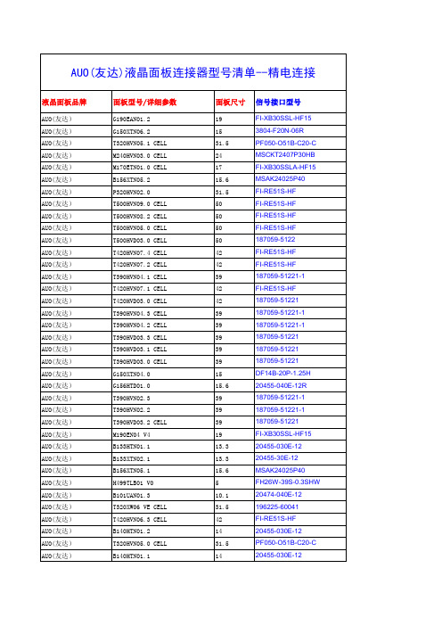
面板尺寸
19 15 31.5 24 17 15.6 31.5 50 50 50 50 42 42 39 42 42 39 39 39 39 39 15 15.6 39 39 39 19 13.3 13.3 15.6 5 10.1 31.5 42 14 31.5 14
信号接口型号
FI-XB30SSL-HF15 3804-F20N-06R PF050-O51B-C20-C MSCKT2407P30HB FI-XB30SSLA-HF15 MSAK24025P40 FI-RE51S-HF FI-RE51S-HF FI-RE51S-HF FI-RE51S-HF 187059-5122 FI-RE51S-HF FI-RE51S-HF 187059-51221-1 FI-RE51S-HF 187059-51221 187059-51221-1 187059-51221-1 187059-51221 187059-51221 187059-51221 DF14B-20P-1.25H 20455-040E-12R 187059-51221-1 187059-51221-1 187059-51221 FI-XB30SSL-HF15 20455-030E-12 20455-30E-12 MSAK24025P40 FH26W-39S-0.3SHW 20474-040E-12 196225-60041 FI-RE51S-HF 20455-030E-12 PF050-O51B-C20-C 20455-030E-12
AUO(友达) AUO(友达) AUO(友达) AUO(友达) AUO(友达) AUO(友达) AUO(友达) AUO(友达) AUO(友达) AUO(友达) AUO(友达) AUO(友达) AUO(友达) AUO(友达) AUO(友达) AUO(友达) AUO(友达) AUO(友达) AUO(友达) AUO(友达) AUO(友达) AUO(友达) AUO(友达) AUO(友达) AUO(友达) AUO(友达) AUO(友达) AUO(友达) AUO(友达) AUO(友达) AUO(友达) AUO(友达) AUO(友达) AUO(友达) AUO(友达) AUO(友达) AUO(友达) AUO(友达) AUO(友达) AUO(友达) AUO(友达) AUO(友达)
SSD1702T1R1中文资料
元器件交易网
TABLE OF CONTENTS
1. 2. 3. 4. 5. 6. 7. 8. 9. 10. 11. 12. 13. 14. 15. 16. 17. 18. 19. GENERAL DESCRIPTION ................................................................................................................ 5 FEATURES ........................................................................................................................................ 5 ORDERING INFORMATION ............................................................................................................. 5 BLOCK DIAGRAM ............................................................................................................................ 7 DIE PAD COORDINATES ................................................................................................................. 8 TAB PACKAGE PIN ASSIGNMENT............................................................................................... 13 PIN DESCRIPTION.......................................................................................................................... 19 FUNCTIONAL BLOCK DESCRIPTIONS ........................................................................................ 22 FUNCTIONAL OPERATIONS ......................................................................................................... 24 DISPLAY DATA AND DRIVER OUTPUT PINS MAPPING ............................................................ 26 PRECAUTION.................................................................................................................................. 27 MAXIMUM RATINGS....................................................................................................................... 28 DC CHARACTERISTICS................................................................................................................. 29 AC CHARACTERISTICS................................................................................................................. 31 APPLICATION EXAMPLES OF COMMON DRIVERS ................................................................... 35 APPLICATION EXAMPLES OF SEGMENT DRIVERS .................................................................. 37 TIMING CHART OF CASCADE CONNECTION OF SEGMENT DRIVERS................................... 38 APPLICATION EXAMPLES ............................................................................................................ 39 TAB PACKAGE DETAIL DIMENSIONS ......................................................................................... 40
罗米 GL 170G 新一代水平中心轴磨制中心说明书

A Nova Geração do Centro de TorneamentoGL 170G garante flexibilidade, rapidez, precisão e alta produtividade para usinagem deGRÁFICO DEPOTÊNCIALA YOUT DE TRABALHOAparelho de pinças - C42Placa hidráulica BB (*)139 99Capacidade máxima de barras - Ø 42 mmCapacidade máxima de barras - Ø 51 mmØ 175Capacidade máxima de barras - Ø 42 mm Placa hidráulica BH (*)125 85Ø 165Aparelho de pinças - C60(aplicado somente como execução especial) Capacidade máxima de barras - Ø 60 mm(*) Serrilhado em milímetros 1,5 mm x 60°S errilhado em polegadas 1/16“ x 90°133 163Ø 180 Ø 170Ø 134117 132 Ø 150 Ø 140Ø 10630Ø 410 (sobre proteções)Ø 340 (sobre ASA da mesa)55510776Ø 165 (máx. sobre mesa)F a c e i n t e r n a312 (até centro eixo-árvore)proteção doaparador de peças (**)proteçãoP l a c a “G a n g ”(**) Equipamento opcional28538 (***)192855F a c e d o e i x o -ár v o r eF a c e d o e i x o -ár v o r ePlaca BH-M 165Placa BH-D 175Aparelho de pinça - C4238 (***)Aparelho de pinça - C6028538 (***)12F a c e d o e i x o -ár v o r eF a c e d o e i x o -ár v o r e28538 (***)19Utilizar para deslocar o suporte 20 mm para frente No caso de se deslocar o suporte para frente, é necessário trocar a posição da chaveta.(***) Espaço ocupado pelo puxador de barras (com ou sem bedame)Capacidade do aparador:- Ø máx. (barra): 50,8 mm (2”)- Comprimento: 90 mm - Carga máxima: 2 Kg- Z = 395+ Z = 5180 + X = 2- X = 46060025545205553555er o v r á-o x i e o d e c a F 19,50 12H8325835 55 55 358+ 1,5+ 0,1 0Curso dos eixosLayout de trabalho (dimensões em mm)Curso dos Eixos (dimensões em mm)Layout de trabalho (dimensões em mm)Layout de trabalho (dimensões em mm)São Paulo / Grande São Paulo / ABCD / S.J. dos Campos e Litoral ..............(11) 96300 8826S anta Bárbara D’Oeste e Região ..................................................................(19) 3455 9735Rio de Janeiro e Espírito Santo ....................................................................(21) 98126 5230R ibeirão Preto e Região ...............................................................................(16) 99761 0261Minas Gerais e Região Centro-Oeste ...........................................................(31) 3361 2526Paraná e Santa Catarina ..............................................................................(41) 3333 6941Rio Grande do Sul ........................................................................................(51) 99999 3121Regiões Norte e Nordeste ...........................................................................(71) 99981 4803ROMI S.A.Rod. SP 304, km 141,5Santa Bárbara d’Oeste/SP 13453-900 - Brasil (19) 3455 9735***************W W W.R O M I.C O MM A Q F E R @R O M I.C O MCapacidadeDiâmetro máximo torneávelDiâmetro admissível sobre a proteção do eixo Z Curso transversal do carro (eixo X)Curso longitudinal do carro (Eixo Z)Cabeçote Nariz do eixo-árvoreDiâmetro do furo do eixo-árvore Capacidade de barras (diâmetro)Faixa de velocidades AvançosAvanço rápido transversal (eixo X) Avanço rápido no eixo longitudinal (eixo Z)Porta-Ferramentas Gang Tools Superfície da mesa Número de rasgos “T”Suporte de ferram. torneam. externo (secção)Suporte de ferram. torneam. interno (diâmetro)Potência InstaladaMotor principal ca (reg. S3 - 15 min)Potência total instaladaDimensões e peso (aproximados)Área ocupada (frente x lateral)Peso líquido aproximadomm mm mm mm ASA mm mm rpm m/min m/min mm -mm mm cv / kW kVA mm kg170410450300A2-5”6042 / 516 a 6.0003630180 x 550320 x 20Ø 2515 / 11202.200 x 1.9002.600Sistema Gang Tools para suportes porta-ferramentas: inclinação 60°, facilidade de acesso do operador aos suportes de ferramentas e escoamento de cavacosEstrutura monobloco de ferro fundido de alta qualidadeCabeçote equipado com placas isolantes, que minimizam a transferência de calor do cartucho para a baseR O M I G L 170G N G / P O / A A / 042022 - F o t o s i l u s t r a t i v a s - E s p e c i f i c a çõe s t éc n i c a s s u j e i t a s a a l t e r a çõe s s e m p r év i o a v i s o - P o r f a v o r , r e c i c l e .(*) Sem transportador de cavacos。
赛米控丹佛斯 SEMITRANS IGBT模块 SKM150GB17E4G 数据表
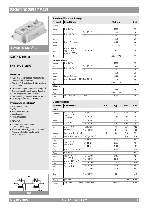
Rev. 1.0–13.11.20171SEMITRANS ®3GBIGBT4 ModulesSKM150GB17E4G Features•IGBT4 = 4. generation medium fast trench IGBT (Infineon)•CAL4 = Soft switching 4. Generation CAL-Diode•Insulated copper baseplate using DBC Technology (Direct Copper Bonding) •With integrated Gate resistor•For switching frequencies up to 8kHz •UL recognized, file no. E63532Typical Applications*•AC inverter drives •UPS•Electronic welders •Wind power •Public transportRemarks•Case temperature limited to T c = 125°C max.•Recommended T op = -40 ... +150°C •Product reliability results valid for T j = 150°CAbsolute Maximum Ratings SymbolConditions Values UnitIGBT V CES T j =25°C 1700V I C T j =175°CT c =25°C 242A T c =80°C187A I Cnom 150A I CRMI CRM = 3xI Cnom 450A V GES -20 (20)V t psc V CC =1000V V GE ≤ 15V V CES ≤ 1700V T j =150°C10µs T j -40...175°C Inverse diodeV RRM T j =25°C 1700V I F T j =175°CT c =25°C 163A T c =80°C121A I Fnom 150A I FRM I FRM = 2xI Fnom300A I FSM t p =10ms, sin 180°, T j =25°C918A T j -40...175°C Module I t(RMS)500A T stg -40 (125)°C V isolAC sinus 50 Hz, t =1min4000VCharacteristics SymbolConditionsmin.typ.max.UnitIGBT V CE(sat)I C =150A V GE =15V chiplevel T j =25°C 1.90 2.21V T j =150°C 2.35 2.60V V CE0chiplevel T j =25°C 0.800.90V T j =150°C 0.700.80V r CE V GE =15V chiplevelT j =25°C 7.38.7m ΩT j =150°C1112m ΩV GE(th)V GE =V CE , I C =6mA5.2 5.86.4V I CES V GE =0V,V CE =1700V, T j =25°C 2.0mA C ies V CE =25V V GE =0Vf =1MHz 13.6nF C oes f =1MHz 0.53nF C res f =1MHz 0.44nF Q G V GE =- 8 V...+ 15 V 1200nC R Gint T j =25°C 4.3Ωt d(on)V CC =1200V I C =150AV GE =+15/-15V R G on =1ΩR G off =1ΩT j =150°C 205ns t r T j =150°C 23.5ns E on T j =150°C 39mJ t d(off)T j =150°C 550ns t f T j =150°C 150ns E off T j =150°C 59mJR th(j-c)per IGBT0.161K/W R th(c-s)per IGBT (λgrease =0.81 W/(m*K))0.064K/W2Rev. 1.0–13.11.2017© by SEMIKRONSEMITRANS ®3GBIGBT4 ModulesSKM150GB17E4G Features•IGBT4 = 4. generation medium fast trench IGBT (Infineon)•CAL4 = Soft switching 4. Generation CAL-Diode•Insulated copper baseplate using DBC Technology (Direct Copper Bonding) •With integrated Gate resistor•For switching frequencies up to 8kHz •UL recognized, file no. E63532Typical Applications*•AC inverter drives •UPS•Electronic welders •Wind power •Public transportRemarks•Case temperature limited to T c = 125°C max.•Recommended T op = -40 ... +150°C •Product reliability results valid for T j = 150°CCharacteristics SymbolConditionsmin.typ.max.UnitInverse diodeV F = V EC I F =150AV GE =0V chiplevelT j =25°C 2.00 2.40V T j =150°C 2.14 2.56V V F0chiplevel T j =25°C 1.32 1.56V T j =150°C 1.08 1.22V r Fchiplevel T j =25°C 4.5 5.6m ΩT j =150°C 7.19.0m ΩI RRM I F =150A V GE =±15V V CC =1200V T j =150°C 185A Q rr T j =150°C 49µC E rr T j =150°C33mJR th(j-c)per diode0.356K/W R th(c-s)per diode (λgrease =0.81 W/(m*K))0.072K/W Module L CE 15nH R CC'+EE'measured per switchT C =25°C 0.55m ΩT C =125°C0.85m ΩR th(c-s)1calculated without thermal coupling (λgrease =0.81 W/(m*K))0.017K/W R th(c-s)2including thermal coupling, Ts underneath module (λgrease =0.81 W/(m*K))0.027K/WM s to heat sink M635Nm M t to terminals M62.55Nm Nm w325g© by SEMIKRON Rev. 1.0–13.11.201734Rev. 1.0–13.11.2017© by SEMIKRON© by SEMIKRON Rev. 1.0–13.11.20175GBThis is an electrostatic discharge sensitive device (ESDS), international standard IEC 60747-1, chapter IX.*IMPORTANT INFORMATION AND WARNINGSThe specifications of SEMIKRON products may not be considered as guarantee or assurance of product characteristics ("Beschaffenheitsgarantie"). The specifications of SEMIKRON products describe only the usual characteristics of products to be expected in typical applications, which may still vary depending on the specific application. Therefore, products must be tested for the respective application in advance. Application adjustments may be necessary. The user of SEMIKRON products is responsible for the safety of their applications embedding SEMIKRON products and must take adequate safety measures to prevent the applications from causing a physical injury, fire or other problem if any of SEMIKRON products become faulty. The user is responsible to make sure that the application design is compliant with all applicable laws, regulations, norms and standards. Except as otherwise explicitly approved by SEMIKRON in a written document signed by authorized representatives of SEMIKRON, SEMIKRON products may not be used in any applications where a failure of the product or any consequences of the use thereof can reasonably be expected to result in personal injury. No representation or warranty is given and no liability is assumed with respect to the accuracy, completeness and/or use of any information herein, including without limitation, warranties of non-infringement of intellectual property rights of any third party. SEMIKRON does not assume any liability arising out of the applications or use of any product; neither does it convey any license under its patent rights, copyrights, trade secrets or other intellectual property rights, nor the rights of others. SEMIKRON makes no representation or warranty of non-infringement or alleged non-infringement of intellectual property rights of any third party which may arise from applications. Due to technical requirements our products may contain dangerous substances. For information on the types in question please contact the nearest SEMIKRON sales office. This document supersedes and replaces all information previously supplied and may be superseded by updates. SEMIKRON reserves the right to make changes.6。
G190ETN01.2友达19寸宽温工控液晶屏-杭州旭虹科技有限公司

22
Update 9. Label and Packing
24
Update 10. Outline Drawing
document version 1.0
3/25
Product Specification
AU OPTRONICS CORPORATION
G190ETN01.2
1. Handling Precautions
Product Specification
AU OPTRONICS CORPORATION
G190ETN01.2
() Preliminary Specification (V) Final Specification
Module Model Name
19” SXGA TFT-LCD Module G190ETN01.2
New Description
1.0 2014/04/07 5
Update Power Consumption and Weight
6ห้องสมุดไป่ตู้
Update 2.2 Optical Characteristics
10
Update 4.2 Absolute Ratings of Environment
13
Update 5.1.3 Backlight Unit
Customer
Date
Checked & Approved by
Vito Huang
Date
2014/04/07
Approved by
Prepared by
Date
Vivian Huang
2014/04/04
Note: This Specification is subject to change without notice.
2707C D 型号 G.703 NTU 与 V.35、X.21 接口 - 用户手册说明书

USER MANUALMODEL 2707C, DG.703 NTU with V.35, X.21InterfacesSALES OFFICE (301) 975-1000TECHNICAL SUPPORT Part# 07M2707-UMDoc# 08619U2-001,Rev. BRevised 10/27/06TABLE OF CONTENTS1.0Warranty Information (2)1.1FCC Information (2)1.2CE Notice (2)1.3Service (3)2.0General Information (4)2.1Features (4)2.2Description (4)3.0Configuration (5)3.1DIP Switch Configuration (5)Switch SW1-1 through SW1-8 (6)Switch SW1-1 Line Coding: HDB3 (default) (6)SW1-2 Local Loop: Inactive (default) (7)SW1-6 and SW1-7 Clock Modes (8)SW1-8: Enable/Disable Loop Tests from DTE (8)4.0Installation (9)4.1Connecting To The G.703 Network (9)Connecting the 2707/D (X.21 version) DualCoaxial Cable (75 Ohm) to the G.703 Network (9)Opening the Case (9)Connecting the Twisted Pair (120 Ohm) tothe G.703 Network (10)4.2Connecting The Serial Port (10)Connecting to a “DTE” Device (10)Connecting to a “DCE” Device (10)Configuring the X.21 Interface (2707/D) (10)4.3Power Connection (11)Universal AC Power (100-240VAC) (11)DC Power (12)5.0Operation (13)5.1Power-up (13)5.2LED Status Monitors (13)5.3Local Loop Diagnostics (14)Operating Local Loopback (LL) (14)A Model 2707, G.703 Specifications (15)B Model 2707, Interface Pin Assignment (16)C Model 2707, Interface Pin Assignment (18)D Model 2707, Factory Replacement PartsAnd Accessories (19)1.0 WARRANTY INFORMATIONPatton Electronics warrants all Model 2707 components to be free from defects, and will—at our option—repair or replace the product should it fail within one year from the first date of shipment.This warranty is limited to defects in workmanship or materials, and does not cover customer damage, abuse, or unauthorized modification. If this product fails or does not perform as warranted, your sole recourse shall be repair or replacement as described above. Under no condition shall Patton Electronics be liable for any damages incurred by the use of this product. These damages include, but are not limited to, the following: lost profits, lost savings and incidental or consequential damages arising from the use of or inability to use this product. Patton Electronics spe-cifically disclaims all other warranties, expressed or implied, and the installation or use of this product shall be deemed an acceptance of these terms by the user.1.1FCC INFORMATIONThis equipment has been tested and found to comply with the limits for a Class A digital device, pursuant to Part 15 of the FCC Rules. These limits are designed to provide reasonable protection against harmful interfer-ence when the equipment is operated in a commercial environment. This equipment generates, uses, and can radiate radio frequency energy and, if not installed and used in accordance with the instruction manual, may cause harmful interference to radio communications. Operation of this equipment in a residential area is likely to cause harmful interference in which case the user will be required to correct the interference at his own expense. If this equipment does cause harmful interference to radio or television reception, which can be determined by turning the equipment off and on, the user is encouraged to try to correct the interference by one or more of the following measures:•Reorient or relocate the receiving antenna•Increase the separation between the equipment and receiver •Connect the equipment into an outlet on a circuit different from that to which the receiver is connected1.2CE NOTICEThe CE symbol on your Patton Electronics equipment indicates that it is in compliance with the Electromagnetic Compatibility (EMC) directive and the Low Voltage Directive (LVD) of the Union European (EU). A Cer-tificate of Compliance is available by contacting Technical Support.1.3SERVICEAll warranty and nonwarranty repairs must be returned freight prepaid and insured to Patton Electronics. All returns must have a Return Mate-rials Authorization number on the outside of the shipping container. This number may be obtained from Patton Electronics Technical Services at:T el: (301) 975-1007E-mail: ******************URL: Note Packages received without an RMA number will not beaccepted.Patton Electronics' technical staff is also available to answer any ques-tions that might arise concerning the installation or use of your Patton Model 2707. T echnical Service hours: 8AM to 5PM EST, Monday through Friday.2.0 GENERAL INFORMATIONThank you for your purchase of this Patton Electronics product. This product has been thoroughly inspected and tested and is warranted for One Y ear parts and labor. If any questions or problems arise during installation or use of this product, please do not hesitate to contact Pat-ton Electronics Technical Support at (301) 975-1007.2.1FEATURES•T erminates G.703 E1 service (2.048 Mbps)•Available in low-cost standalone or rack-mountable versions•X.21 and V.35•Switch-selectable AMI or HDB3 line encoding options•Switch-selectable DTE/DCE modes for X.21 version•75 Ohm dual coax and 120 Ohm twisted-pair G.703 connections •Local loopback diagnostics•Internal, External, and G.703 network timing•CE approval•100-240VAC & 48VDC power options•Conforms to ONP requirements CTR 12 for connection to international T elecom networks2.2DESCRIPTIONThe Model 2707 receives clear channel E1/G.703 (2.048 Mbps) data from the telco's digital data network. The Model 2707 terminates the G.703 telco interface and converts the data for transmission to a user-oriented serial (X.21 and V.35). The 2707 can connect to a Router, FRAD, P ABX or Multiplexer over its serial interface at 2.048 Mbps.3.0 CONFIGURATIONThe Model 2707 features configuration capability via hardware DIP switches. This section describes all possible DIP switch configurations of the Model 2707.3.1DIP SWITCH CONFIGURATIONThe Model 2707 has one internal DIP switch that allow configuration for a wide range of applications. The switch is accessed from the underside of the 2707. Figure 1 shows the location of the DIP switch on the bottom of the printed circuit board.Figure 1. Underside of Model 2707, Showing Location of DIP SwitchesThe Model 2707 DIP switch can be configured as either “ON” or “OFF”. Figure 2 shows the orientation of the DIP switch with respect to ON/OFF positions.Figure 2. Close up of configuration switchesSwitch SW1-1 through SW1-8Switch SW1-1 Line Coding: HDB3 (default)Use Switch SW1-1 to control the Network Line Coding options. Set these options to be the same as the Line Coding given to you by your Service Provider. If you are using two Model 2707s together as short range modems, set both units to HDB3.Table 1: Switch Set 1 SummaryPositionFunction Factory Default Selected Option SW1-1Line Code OFF HDB3SW1-2LLB OFF OFF SW1-3Reserved SW1-4Reserved SW1-5Reserved SW1-6Clock Mode OFF Received Recovered SW1-7Clock Mode OFF Received Recovered SW1-8TM from DTE OFF EnabledSW1-1Line Encoding OffHDB3On AMIOptions: HDB3, AMIHDB3: In this line coding, the transmitter substitutes a deliberate bipolar violation when excessive zeros in the data stream are detected. The receiver recognizes these special violations and decodes them as zeros. This method enables the network to meet minimum pulse density requirements. Unless AMI is required in your application, HDB3 should be used whenever possible.AMI: Alternate Mark Inversion defines a pulse as a “mark,” a binary one, as opposed to a zero. In an E1 network connection, signals are transmitted as a sequence of ones and zeros. Ones are sent as pulses, and zeros are sent as spaces, i.e., no pulse. Every other pulse is inverted from the previous pulse in polarity, so that the signal can be effectively transmitted. This means, however, that a long sequence of zeros in the data stream will cause problems, since the NTU receiving the signal relies on the signal to recover the 2.048 Mbps clock.If you must use AMI, you should ensure that the data terminal equipment connected to the unit provides a minimally acceptable pulse density. For this reason, there are advantages to using HDB3 instead. AMI coding does not inherently account for ones density. To meet this requirement, the user should ensure that the data inherently meets pulse density requirements.SW1-2 Local Loop: Inactive (default)Use SW1-2 to activate/deactivate local loopback test.Table 2: SW1-2 Local Loop SettingSW1-2SettingOff Local Loopback InactiveOn Local Loopback ActiveSW1-6 and SW1-7 Clock ModesUse Switches SW1-6 and SW1-7 to configure the 2707 for internal, external, or receive recover clock mode.Table 3: SW1-6 and SW1-7 Clock ModesSW1-6SW1-7Clock ModeON ON Network (Received Recovered)ON OFF InternalOFF ON ExternalOFF OFF Network (Received Recovered) Network Clock Transmitter timing is derived usingthe received line signal (receivedrecovered) from the network.Internal Clock Transmitter timing is derived froman internal clock source.External Clock Transmitter timing is derived fromDTE terminal timing.SW1-8: Enable/Disable Loop Tests from DTEUse Switch SW1-8 to allow Model 2707 to enter loopback tests when the DTE raises the appropriate loop request pin.SW1-8SettingOff Response to DTE Loopback Request EnabledOn Response to DTE Loopback Request Disabled4.0 INSTALLATIONOnce the Model 2707 is properly configured, it is ready to connect to the G.703 interface, to the serial port, and to the power source. This section describes how to make these connections.4.1CONNECTING TO THE G.703 NETWORKThe Power, G.703 and serial Line connections are located on the rear panel of the Model 2707. The following sections describe operation of these connections.Connecting the 2707/D (X.21 version) Dual Coaxial Cable (75 Ohm) to the G.703 NetworkThe Model 2707/D (X.21 version) is equipped with dual female BNCs (TX and RX) for connection to a 75 Ohm dual coax G.703 network inter-face. If your G.703 network terminates via dual coaxial cable, use the diagram below to make the proper connections. (SeeFigure 3).Figure 3. Rear Panel, Showing Location of ConnectorsNote The outer conductor of the coax cables are isolated from system earth ground.When using the 75 Ohm interface, jumper straps JP2, JP6, JP7, and JP5 must be installed over the jumpers. The jumpers are located next to the BNC connectors. Refer to the following section to open the case. Open the case and install jumper straps for JP2, JP6, JP7, and JP5. Opening the CaseOpen the case by inserting a screwdriver into the slots and twist the screwdriver head slightly. The top half of the case will separate from the lower half of the case. Take caution not to damage any of the PC board mounted components.Connecting the Twisted Pair (120 Ohm) to the G.703 NetworkThe Model 2707 is equipped with a single RJ-48C jack for connections to a 120 Ohm twisted pair G.703 network interface. If your G.703 network terminates via RJ-48C, use Figure 4 below to connect the 120 Ohm G.703 network channel.Figure 4. G.703 120 Ohm Connection4.2CONNECTING THE SERIAL PORTThe Model 2707/C and D supports V.35, X.21 serial port connections. This section describes how to connect the serial ports to your terminal equipment.Connecting to a “DTE” DeviceThe serial port on the 2707/C (V.35 version) is hard-wired as a DCE. Therefore these modules “want” to plug into a DTE such as a terminal, PC or host. When making the connection to your DTE device, use a straight through cable of the shortest possible length—we recommend 6 feet or less. When purchasing or constructing an interface cable, please refer to the pin diagrams in Appendix C as a guide.Connecting to a “DCE” DeviceIf the Model 2707 serial interface is hard-wired as a DCE (all except the X.21 version), you must use a null modem cable when connecting to a modem, multiplexer or other DCE device. This cable should be of the shortest possible length—we recommend 6 feet or less.Configuring the X.21 Interface (2707/D)The serial port on the X.21 interface is default wired as a DCE, but may be switched to a DTE. This is done by reversing the orientation of the DCE/DTE strap, as described below:T o reverse DCE/DTE orientation, remove the top case. Refer to “Open-ing the Case” on page 9.The DCE/DTE strap is located near the DB15 connector on the top side of the board. The arrows on the top of the strap indicate the configura-tion of the X.21 port (for example, if the DCE arrows are pointing toward the DB-15 connector, the X.21 port is wired as a DCE). Reverse the DCE/DTE orientation by pulling the strap out of its socket, rotating it 180º, then plugging the strap back into the socket. Y ou will see that the DCE/DTE arrows now point in the opposite directions, showing the new configuration of the X.21 port.Note If the 2707/D is configured as a DTE, the clocking mode must be set for external clock.4.3POWER CONNECTIONUniversal AC Power (100-240VAC)The Model 2707 uses a 5VDC, 2A universal input 100-240VAC, power supply (center pin is +5V). The universal input power supply has a male IEC-320 power entry connector. This power supply connects to the Model 2707 by means of a barrel jack on the rear panel. Many interna-tional power cords are available for the universal power supply.The Model 2707 powers up as soon as it is plugged into an AC outlet--there is no power switch.DC PowerThe 36-60 VDC DC to DC adapter is supplied with the DC version of the Model 2707. The black and red leads plug into a DC source (nominal 48VDC) and the barrel power connector plugs into the barrel power sup-ply jack on the 2707. (See Figure 5).Figure 5. Connecting DC Power to the 2707 DC Power SupplyWARNING There are no user-serviceable parts in the power supply section of the Model 2707. Contact Patton Electronics Technical support at +1 (301) 975-1007, via our web site at , or by **************************,formoreinfor-mation.5.0 OPERATIONWhen the Model 2707 has been properly configured and installed, it should operate transparently. This sections describes power-up, LED status monitors, and the built-in loopback test modes.5.1POWER-UPBefore applying power to the Model 2707, please read section 4.3, “Power Connection” on page 11 and ensure that the unit is properly connected to the appropriate power source.5.2LED STATUS MONITORSThe Model 2707 features six front panel LEDs that monitor connections on the G.703 and signaling, error and test modes. Figure 6 shows the front panel location of each LED. Descriptions of each LED follow Figure 6.Figure 6. 2707 Front PanelE1 Link(Active Green) Solid green (On) indicates thatthe end to end E1 Link is up, signifying that thelink is active. The E1 Link LED is Off when thelink is down.TD & RD Glows yellow to indicate an idle condition ofBinary “1” data on the respective terminal inter-face signals. Green indicates Binary “0” data.TM(Active Y ellow) Solid Y ellow indicates anActive Test Mode. The unit may be placedin test mode by the local user.5.3LOCAL LOOP DIAGNOSTICSThe Model 2707 offers V.54 loop diagnostics. Use these diagnostics to test the NTU and any communication links. This test can be activated via DIP switches or via signals on the Model 2707 serial port interface. Operating Local Loopback (LL)The Local Loopback (LL) test checks the operation of the local Model 2707, and is performed separately on each unit. Any data sent to the local Model 2707 in this test mode will be echoed (returned) to the user device (i.e., characters typed on the keyboard of a terminal will appear on the terminal screen).Figure 7. Local Loopback for a Network Termination ApplicationT o perform a LL test, follow these steps:1.Activate LL. This may be done in one of two ways:–Place the DIP switch SW1-2 to the “ON” position.–Activate the “LL” signal on the DTE (2707/C only). If you are notsure which lead is the “LL” signal, please refer to Appendix C.2.Verify that the data terminal equipment is operating properly and canbe used for a test.APPENDIX AMODEL 2707, G.703 SPECIFICATIONSNetwork Data Rate: 2.048 MbpsNetwork Connector:RJ-48C/Dual Coax BNC (2707/D)Nominal Impedance:75/120 OhmLine Coding:Selectable AMI or HDB3Line Framing:G.703 (Unframed)Clocking:Internal or Network (Receive Recover) Distance:Maximum 1.8 km (6,000 ft.) on 24 AWGCableConfiguration:One 8-Position DIP SwitchesPower Supply:+5VDC External power supply/100-240VAC,50-60Hz, 0.4A; or 48VDC Power Supply Humidity:Up to 90% non-condensingTemperature:0 to 50˚ CDimensions: 9.0 x 5.3 x 2.0 cm (3.5”L x 2.1”W x 0.78”H)APPENDIX BMODEL 2707, INTERFACE PIN ASSIGNMENTV.35 Interface(M/34F Female Connector)(DCE Configuration)Pin #SignalB SGND (Signal Ground)C RTS (Request to Send)D CTS (Clear to Send)E DSR (Data Set Ready)F CD (Carrier Detect)H DTR (Data Terminal Ready)L LLB (Local Line Loop)M TM (Test Mode)N RDL (Remote Digital Loop)P TD (Transmit Data)R RD (Receive Data)S TD/ (Transmit Data-B)T RD/ (Receive Data-B)U XTC (External Transmit Clock)V RC (Receive Timing)W XTC/ (External Transmit Clock)X RC/ (Receive Timing)Y TC (Transmit Clock-A)AA TC/ (Transmit Clock-B)APPENDIX B - ContinuedV.35 TO V.35 (STRAIGHT-THROUGH CABLE) PINOUT V.35 TO V.35 (CROSS OVER CABLE) PIN OUTPIN Function PIN Function PINA Frame Ground A Frame Ground AB Signal Ground B Signal Ground BC RTS C DCD FD NC D NC DE DSR E DTR HF DCD F RTS C H DTR H DSR E K NC K NC K L NC L NC L P TD (A)P RD (A)R R RD (A)R TD (A)P S TD (B)S RD (B)T T RD (B)T TD (B)S U SCTE (A)U RT (A)V V RT (A)V SCTE (A)U W SCTE (B)W RT (B)X X RT (B)X SCTE (B)W Y NC Y NC Y AA NC AA NC AAX.21 Interface(DB-15 Female Connector)(DTE/DCE Configuration)Pin #Signal1Frame Ground2T (T ransmit Data-A)3 C (Control-A)4R (Receive Data-A)5I (Indication-A)6S (Signal Element Timing-A)7BT (Byte Timing-A)8SGND (Signal Ground)9T/ (Transmit Data-B)10C/ (Control-B)11R/ (Receive Data-B)12I/ (Indication-B)13S/ (Signal Element Timing-B)14BT/ (Byte Timing-B)AND ACCESSORIESModel #Description 2707/C G.703 NTU with a V.35 interface 2707/D G.703 NTU with an X.21 interface2707/I G.703 NTU w/ 10Base-T EN interface 0805US American Power Cord0805EUR European Power Cord CEE 70805UK United Kingdom Power Cord0805AUS Australia/New Zealand Power Cord 0805DEN Denmark Power Cord0805FR France/Belgium Power Cord0805IN India Power Cord0805IS Israel Power Cord0805JAP Japan Power Cord0805SW Switzerland Power Cord08055DCUI Universal Input Power Supply07M2707User ManualCopyright © 2006Patton Electronics CompanyAll Rights Reserved.。
IXYS CORPORATION H82N120C3 高速 IGBT 数据手册说明书
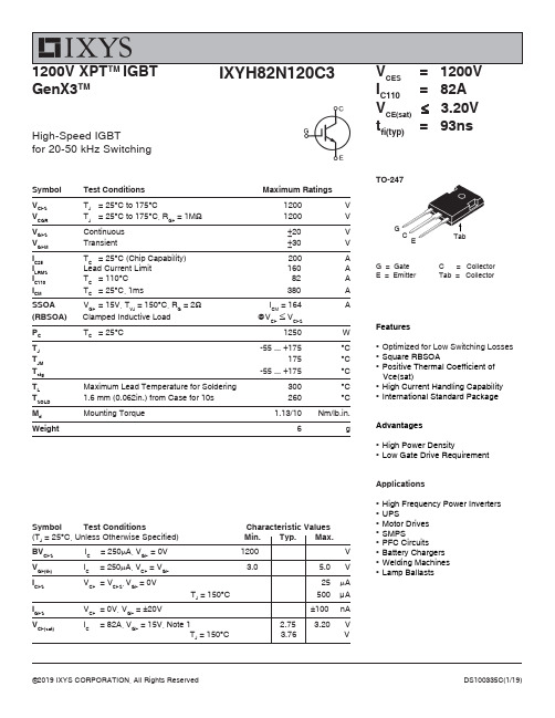
CES I C110= 82A V CE(sat) ≤ 3.20V t fi(typ)= 93nsG = Gate C = Collector E = Emitter Tab = CollectorTO-247High-Speed IGBTfor 20-50 kHz SwitchingFeatures●Optimized for Low Switching Losses ●Square RBSOA ●Positive Thermal Coefficient of Vce(sat)●High Current Handling Capability ●International Standard PackageAdvantages●High Power Density●Low Gate Drive RequirementApplications●High Frequency Power Inverters ●UPS●Motor Drives ●SMPS●PFC Circuits ●Battery Chargers ●Welding Machines ●Lamp BallastsSymbol Test Conditions Characteristic Values (T J = 25︒C, Unless Otherwise Specified) Min. Typ. Max.BV CES I C = 250μA, V GE = 0V 1200 V V GE(th)I C= 250μA, V CE = V GE3.05.0VI CES V CE = V CES , V GE = 0V25μA T J = 150︒C 500 μA I GES V CE = 0V, V GE = ±20V±100 nAV CE(sat)I C = 82A, V GE = 15V, Note 12.753.20 V T J = 150︒C3.76 VSymbol Test ConditionsMaximum Ratings V CES T J = 25°C to 175°C1200V V CGR T J = 25°C to 175°C, R GE = 1M Ω 1200V V GES Continuous ±20V V GEM Transient±30VI C25T C = 25°C (Chip Capability) 200A I LRMS Lead Current Limit 160 A I C110T C = 110°C 82A I CMT C = 25°C, 1ms 380ASSOA V GE = 15V, T VJ = 150°C, R G = 2Ω I CM = 164A (RBSOA) Clamped Inductive Load @V CE ≤ V CES P C T C = 25°C1250W T J -55 ... +175°CT JM 175°C T stg -55 ... +175°CT LMaximum Lead Temperature for Soldering 300°CT SOLD 1.6 mm (0.062in.) from Case for 10s 260 °C M d Mounting Torque 1.13/10Nm/lb.in.Weight6g1200V XPT TM IGBT GenX3TMIXYS Reserves the Right to Change Limits, Test Conditions, and Dimensions.Notes:1. Pulse test, t ≤ 300μs, duty cycle, d ≤ 2%.2. Switching times & energy losses may increase for higher V CE (clamp), T J or R G .Symbol Test Conditions (T J = 25°C Unless Otherwise Specified)fs I C = 60A, V CE = 10V, Note 1 30 50C ie sC oes V CE = 25V, V GE C resQ g(on)Q ge I C = 82A, V GE = 15V, V Q gc d(on)Fig. 1. Output Characteristics @ T 6080100120140160I C - A m p e r e sIXYS Reserves the Right to Change Limits, Test Conditions, and Dimensions.Fig. 7. Transconductance304050607080g f s - S i e m e n sFig. 12. Inductive Switching Energy Loss vs.Gate Resistance345678E o f f - M i l l i J o u l e sE off E on T J = 125oC , V GE = 15V V CE = 600VIXYS Reserves the Right to Change Limits, Test Conditions, and Dimensions.Fig. 18. Inductive Turn-on Switching Times vs.Gate Resistance6080100120140160 r i - N a n o s e c o n d st r i t d(on)T J = 125oC, V GE = 15V V CE = 600VI C = 80ATO-247 (IXYH) Outline1 - Gate2,4 - Collector3 -EmitterDisclaimer Notice - Information furnished is believed to be accurate and reliable. However, users should independently evaluate the suitability of and test each product selected for their own applications. Littelfuse products are not designed for, and may not be used in, all applications. Read complete Disclaimer Notice at /disclaimer-electronics. IXYS Reserves the Right to Change Limits, Test Conditions, and Dimensions.。
Moxa V2201 系列 Intel Atom E3800 DIN 軌道電腦說明说明书

V2201系列Intel®Atom®E3800DIN軌道電腦,具有2個用於無線模組的mini-PCIe擴充插槽特色與優點•Intel Atom®E3800系列處理器,提供三種效能選項•用於無線模組的雙mini-PCIe插槽,支援Wi-Fi、3G、LTE和GPS1•-40至85°C系統操作溫度(安裝LTE模組時為-40至70°C)1•各種介面:2個串列埠,2個乙太網路LAN連接埠,4個DI、4個DO、SD、USB、HDMI、無線•EN61000-6-2和EN61000-6-4認證2;符合重工業的EMC標準•高達5Grms的防震保護以及100g/11ms的抗撞擊保護•開機即用的Debian9、Windows Embedded Standard7以及Windows10Embedded IoT Enterprise2016LTSB平台•Moxa Proactive Monitoring支援監控系統硬體狀態•Moxa Smart Recovery支援系統啟動故障快速復原(僅W7E)認證簡介V2201系列超輕巧x86嵌入式電腦是以Intel®Atom™E3800系列處理器為架構,採用最可靠的I/O設計以發揮最大互聯性,並且可支援雙重無線模組,使其適用於各種通訊應用範圍。
1本系列電腦的散熱設計可確保系統能夠於-40至85°C溫度範圍(若安裝專用Moxa無線模組,則支援-40至70°C)可靠運作。
V2201系列可支援「Moxa硬體監控」,可監控裝置的I/O狀態並發出警報、監控系統溫度並發出警報,以及管理系統電源。
密切監控系統狀態將使系統快速從故障中復原,為您的應用提供最可靠的平台。
應用•遠端終端裝置(RTU)•資料擷取•M2M通訊(智慧閘道)•數位看板•工廠自動化•車載監控/數據記錄器(交通運輸)•可編程路由器•能源使用最佳化•預測性維護•資產管理1.無線模組需另購。
艾顿Moeller系列EMSDOL起动器 170099 产品介绍说明书

Eaton 170099Eaton Moeller® series EMS DOL starter, 24 V DC, 0,18 - 2,4 A,PTB 13 ATEX 3003, Push in terminalsAllgemeine spezifikationEaton Moeller® series EMS DOL starter170099160 mm60 mm155 mm0.3 kgIEC/EN 61000-4-3Certified by UL for use in CanadaUL File No.: E29096PTB 13 ATEX 3003IEC/EN 60947-4-2IEC/EN 60947-5UL Category Control No.: NLDX, NLDX7 UL 508CSA-C22.2 No. 14CEUL508UL report applies to both US and CanadaIEC/EN 61000-4-2, Level 3UL 4015081665969EMS-DO-T-2,4-24VDCProduct Name Catalog Number Product Length/Depth Product Height Product Width Product Weight Certifications EANModel CodeExternal reset possibleDOL startingMotor protectionTemperature compensated overload protection If ≥ 33 %, pick-up time of 120 s, Magnitude Imax > Irated ((Imax - Imin)/Imax)If ≥ 33 %, pick-up time of 120 s, Magnitude Imax < Irated ((Imax - Imin)/Imax)If ≥ 67 %, pick-up time of 1.8 s, Magnitude Imax < Irated ((Imax - Imin)/Imax)If ≥ 67 %, pick-up time of 1.8 s, Magnitude Imax > Irated ((Imax - Imin)/Imax)CLASS 10NoIP20IP20 (according to IEC/EN 60529, EN 50178, VBG 4)30,000,000 OperationsDirect starterTop-hat rail fixing (according to IEC/EN 60715, 35 mm)Rail mounting possibleVerticalMotor feeder at bottom7200 Operations/h (pulse pause time 50:50)0.18 A2.4 AIII2Functions Balance monitoringClassConnection to SmartWire-DTDegree of protectionLifespan, electricalModelMounting methodMounting positionOperating frequencyOverload release current setting - minOverload release current setting - maxOvervoltage categoryPollution degreeProduct categoryElectronic motor starter 6000 V AC20 min (automatic restart)2 min (manual startup)≤ 5 % (input voltage)2 x (0.75 - 2.5) mm², flexible with ferrule1 x (0.75 - 2.5) mm², solid2 x (0.75 - 1.5) mm², flexible, with twin ferrule Minimum length 10 mm.1 x (20 - 14), flexible with ferrule2 x (20 - 16), flexible with twin ferrule1 x (20 - 14), solidDOL starter (complete device)DC -25 °C60 °C-40 °C80 °CCondensation: prevent with appropriate measuresDesigned for operation in industrial environments. The use in residential environments could cause electrical interference so that addition suppression must be planned.8 kV2 kVAccording to IEC/EN 61000-4-4, level 36 kV3 V/m at 2.0 - 2.7 GHz (according to IEC EN 61000-4-3)10 V/m at 1.4 - 2 GHz (according to IEC EN 61000-4-3)10 V/m at 800 - 1000 MHz (according to IEC EN 61000-4-3) 10 V (according to IEC/EN 61000-4-6)Class A (EN 55011, emitted interference, line-conducted) Class A (EN 61000-6-3, emitted interference, radiated)1 kV, symmetrical, power pulses (Surge), EMC2 kV, asymmetrical, power pulses (Surge), EMCAccording to IEC/EN 61000-4-5, power pulses (Surge), EMCRated impulse withstand voltage (Uimp)Recovery timeResidual ripple Terminal capacityTerminal capacity (AWG) TypeVoltage type Ambient operating temperature - min Ambient operating temperature - max Ambient storage temperature - min Ambient storage temperature - max Environmental conditionsAir dischargeBurst impulseContact dischargeElectromagnetic fieldsImmunity to line-conducted interference Radio interference classSurge rating500 V AC, between supply voltage, control voltage and switch voltage according to IEC/EN60947-1500 V AC, between feedback signal output and switch voltage according to IEC/EN60947-140 mA (without feedback signal)5 mA (Actuating circuit - ON, L, R)0 A0 V0 V0 V0 V24 V24 V2.4 A3 A2.4 A2.4 A2.4 A0.15 A2 A 111ATEX dust-ex-protection, II (2) G [Ex e] [Ex d] [Ex px]ATEX dust-ex-protection, II (2) D [Ex t] [Ex p]500 V AC; Between supply, control, and switching voltages; According to EN50178300 V AC, Between feedback signal output and switch voltage, According to EN 50178300 V AC; Between supply, control, and switching voltages; According to EN50178500 V AC, Between feedback signal output and switch voltage, According to EN 50178316 years; MTTFDΛsu [FIT]: 1550SIL: 2Λdd [FIT]: 31497.9 %, SFFΛsd [FIT]: 0Λdu [FIT]: 47.286,9 %, DC2 W0 WBasic insulationInput currentRated conditional short-circuit current (Iq), type 2, 380 V, 400 V, 415 VRated control supply voltage (Us) at AC, 50 Hz - minRated control supply voltage (Us) at AC, 50 Hz - maxRated control supply voltage (Us) at AC, 60 Hz - minRated control supply voltage (Us) at AC, 60 Hz - maxRated control supply voltage (Us) at DC - minRated control supply voltage (Us) at DC - maxRated operational current (Ie)Rated operational current (Ie) at AC-15, 220 V, 230 V, 240 V Rated operational current (Ie) at AC-3, 380 V, 400 V, 415 V Rated operational current (Ie) at AC-51Rated operational current (Ie) at AC-53A - maxRated operational current (Ie) at AC-53A - minRated operational current (Ie) at DC-13, 24 V Number of auxiliary contacts (normally closed contacts) Number of auxiliary contacts (normally open contacts) Number of contacts (change-over contacts)Explosion safety category for dustSafe isolationSafety parameter (EN ISO 13849-1)Safety parameter (IEC 62061)Equipment heat dissipation, current-dependent Pvid Heat dissipation capacity PdissHeat dissipation per pole, current-dependent Pvid0.37 kW0.75 kW0.75 kW250 V AC/DC42 - 550 V50 kA, 500 V AC: Fuse 16 A gG/gL, Short-circuit protective device, Type “1” coordination, Main conducting paths50 kA, 415 V AC: PKM0-4, Short-circuit protective device, Type “1” coordination, Main conducting paths15 kA, 415 V AC: PKM0-6,3, Short-circuit protective device, Type “1” coordination, Main conducting pathsA1 - A2: 24 V DC (-20 - +25 %), UAUX, Control section, Input data-3 - 9.6 V DC, Switching level "Low", Actuating circuit (ON, L, R) < 5 V DC, Switching level "confirm Off", Actuating circuit (ON, L, R)19.2 - 30 V DC, Switching level "High", Actuating circuit (ON, L, R)0.7 W2.4 A1 WMeets the product standard's requirements.Meets the product standard's requirements.Meets the product standard's requirements.Meets the product standard's requirements.Meets the product standard's requirements.Does not apply, since the entire switchgear needs to be evaluated.Does not apply, since the entire switchgear needs to be evaluated.Meets the product standard's requirements.Does not apply, since the entire switchgear needs to be evaluated.Meets the product standard's requirements.Does not apply, since the entire switchgear needs to be evaluated.Does not apply, since the entire switchgear needs to be evaluated.Is the panel builder's responsibility.Rated operational power at AC-3, 220/230 V, 50 HzRated operational power at AC-3, 380/400 V, 50 Hz Rated operational power at AC-53A, 380/400 V, 50 Hz Rated operational voltageShort-circuit protection ratingSupply voltageSwitching level Rated operational current for specified heat dissipation (In) Static heat dissipation, non-current-dependent Pvs10.2.2 Corrosion resistance10.2.3.1 Verification of thermal stability of enclosures10.2.3.2 Verification of resistance of insulating materials to normal heat10.2.3.3 Resist. of insul. mat. to abnormal heat/fire by internal elect. effects10.2.4 Resistance to ultra-violet (UV) radiation10.2.5 Lifting10.2.6 Mechanical impact10.2.7 Inscriptions10.3 Degree of protection of assemblies10.4 Clearances and creepage distances10.5 Protection against electric shock10.6 Incorporation of switching devices and components10.7 Internal electrical circuits and connections10.8 Connections for external conductorsEaton Konzern plc Eaton-Haus30 Pembroke-Straße Dublin 4, Irland © 2023 Eaton. Alle Rechte vorbehalten.Eaton ist eine eingetragene Marke.Alle anderen Warenzeichen sind Eigentum ihrer jeweiligen Besitzer./socialmediaIs the panel builder's responsibility.Is the panel builder's responsibility.Is the panel builder's responsibility.Is the panel builder's responsibility.The panel builder is responsible for the temperature rise calculation. Eaton will provide heat dissipation data for the devices.Is the panel builder's responsibility. The specifications for the switchgear must be observed.Is the panel builder's responsibility. The specifications for the switchgear must be observed.The device meets the requirements, provided the information in the instruction leaflet (IL) is observed.Generationenwechsel EMS zu EMS2Einstellen des Motorschutzes EMS MN03407009Z_DE_EN EMS 2 Electronic motor starters - brochure EMS 2 Electronic motor starters - flyereaton-contactors-ems2-reversing-starter-characteristic-curve.eps DA-CE-ETN.EMS-DO-T-2,4-24VDCIL03407198Z Eaton's Elektronischer Motorstarter EMS2DA-CD-ems DA-CS-ems eaton-contactors-ems-dol-starter-dimensions.eps eaton-contactors-3d-drawing-018.eps 10.9.2 Power-frequency electric strength 10.9.3 Impulse withstand voltage 10.9.4 Testing of enclosures made of insulating material 10.10 Temperature rise10.11 Short-circuit rating10.12 Electromagnetic compatibility10.13 Mechanical functionAnmerkungen zur Anwendung Benutzerhandbücher BroschürenCharacteristic curveeCAD modelInstallationsanleitung InstallationsvideosmCAD model Zeichnungen。
Modicon Momentum 170ADI35000 离散输入模块说明书

170ADI35000i s c l a i me r : T h i s d o c u m e n t a t i o n i s n o t i n t e n d e d a s a s u b s t i t u t ef o r a n d i s n o t t o b e u s e d f o r d e t e r m i n i ng s u i t a b i l i t y o r r e l i a b i l i t y o f th e s e p r o d u c t s f o r s p e ci f i c u s e r a p p l i c a t i o n sProduct datasheetCharacteristics170ADI35000discrete input module Modicon Momentum - 32Input 24 V DCMainRange of productModicon Momentum automation platform Product or component type Discrete inputs base DC Group of channels 2 groups of 16 inputs Discrete input number 32 IEC 1131-2 Type 1Discrete input voltage 24 V DC Protective treatmentTCComplementaryDiscrete input logic Positive Input voltage limits 24 V Voltage range- 3...30 V Voltage state 0 guaranteed -3...5 V Voltage state 1 guaranteed 11...30 V Current state 0 guaranteed <= 1.2 mA Current state 1 guaranteed >= 2.5 mA Input resistance 4 kOhmResponse time2.2 ms from state 0 to state 13.3 ms from state 1 to state 0Isolation between channels and bus 500 V AC Power dissipation8.5 W maximum 5.5 W typical Terminals description PLC n°1(14)IN_DIS#14(6)IN_DIS#6(9)IN_DIS#9(11)IN_DIS#11(12)IN_DIS#12(2)IN_DIS#2(15)IN_DIS#15(L+)PW_POS TB(10)IN_DIS#10(4)IN_DIS#4(8)IN_DIS#8(5)IN_DIS#5(16)IN_DIS#16(7)IN_DIS#7(13)IN_DIS#13(1)IN_DIS#1(3)IN_DIS#3(M-)PW_NEGTerminals description PLC n°2(16)IN_DIS#32(4)IN_DIS#20(14)IN_DIS#30TB_1(12)IN_DIS#28(3)IN_DIS#19(13)IN_DIS#29(15)IN_DIS#31(7)IN_DIS#23(5)IN_DIS#21(1L+)PW_POS (2L+)PW_POS (6)IN_DIS#22(10)IN_DIS#26(11)IN_DIS#27(1)IN_DIS#17(2)IN_DIS#18(8)IN_DIS#24(9)IN_DIS#25Marking CELocal signalling 32 LEDs channel status Current consumption <= 250 mA 24 V DC Depth 47.5 mm Height 141.5 mm Width125 mm Product weight0.2 kgEnvironmentProduct certificationsCSA ULResistance to electrostatic discharge 4 kV contact IEC 801-28 kV on air IEC 801-2Resistance to electromagnetic fields 10 V/m 80...1000 MHz IEC 801-3Ambient air temperature for operation 0...60 °C Ambient air temperature for storage -40...85 °CRelative humidity 95 % without condensation Operating altitude<= 5000 mOffer SustainabilitySustainable offer status Green Premium productRoHS (date code: YYWW)Compliant - since 1350 - Schneider Electric declaration of conformity Schneider Electric declaration of conformity REAChReference not containing SVHC above the threshold Reference not containing SVHC above the threshold Product environmental profileAvailableProduct environmental Product end of life instructionsAvailableContractual warrantyWarranty period18 monthsProduct datasheet170ADI35000 Dimensions DrawingsStandard Adapter on a Typical BaseDimensionsProduct datasheet170ADI35000 Mounting and ClearanceMounting on a WallProduct datasheet170ADI35000 Connections and SchemaExternal Wiring Diagrams2-Wire Device3-Wire DevicesProduct datasheet170ADI35000Connections and SchemaInternal Pin ConnectionsRows 1 through 3 show the internal connections between terminals on the I/O base. Rows 4 through 6 show the internal connections on the optional busbar.170ADI35000。
Impinj R700 ETK 使用说明书

Develop business applications using the Impinj IoT device interface, Impinj Octane SDK, the Impinj Octane LLRP toolkit, or Impinj R700 ETK. For more information, contact Impinj using the resources listed below.
NO LICENSE, EXPRESS OR IMPLIED, BY ESTOPPEL OR OTHERWISE, TO ANY PATENT, COPYRIGHT, MASKWORK RIGHT, OR OTHER INTELLECTUALPROPERTY RIGHT IS GRANTED BY THIS DOCUMENT.
Version 1.2
Part Number: 102960-01
© 2021, Impinj, Inc.
Connect antenna
1. Securely mount one or more Impinj-approved antennas in accordance with the antenna manufacturer’s instructions
• Sales: /contact-us • Support: • Developer site: • Postal Address: 400 Fairview Avenue North, Suite 1200, Seattle, WA 98109
Sign into the reader and update firmware if necessary
SINAMICS S210 伺服驱动系统样本
E86060-K4670-A101-B6-76001) SIMATIC HMI / 基于 PC 的自动化系统 操作与监控系统 基于 PC 的自动化系统 E86060-K4680-A101-C5-76001) 工业通信 SIMATIC NET IK PI ST 80/ST PC
E86060-K6710-A101-B8-76001) MD 10.1 SITRAIN 工业培训
E86060-K5710-A111-A5-76001) SIMOGEAR MD 50.1 减速电机 圆柱齿轮减速电机、平行轴减速电机、 锥齿轮减速电机、螺旋蜗轮减速电机以及 蜗轮减速电机 E86060-K5250-A111-A5-76001) 运动控制系统 SIMOTION 生产机械设备 E86060-K4921-A101-A4-5D00
Siemens D 32 · 12/2017 版
3
集成驱动系统
凭借集成驱动系统实现更快上市和更快盈利
SINAMICS 是西门子集成驱动系统的重要组件。SINAMICS 在提升工业生产 过程中的效率、生产率和可用性方面起着举足轻重的作用。 集成驱动系统是西门子对当今驱动与自动化技术所面临的极度复杂性挑战 而给出的指导性解答。全球唯一真正面向整套驱动系统的全面解决方案以 其三位一体的集成概念而著称:横向集成、纵向集成以及生命周期集成, 这些确保了每个驱动组件都能无缝集成到各个驱动系统、各类自动化环 境,甚至于设备的整个生命周期之中。 您将获得:一个从配置到服务的最佳工作流,达到更高的生产率、增效以 及更高的可用性。最终,集成驱动系统将显著缩短上市时间 以及盈利周期。
3
MOTION-CONNECT 接线系统
4
配置工具
5
服务与文档
6
TEL TA703-01-0000 Change Over Module 设置、校准与测试说明书
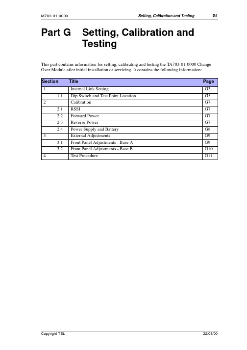
Part G Setting, Calibration andTestingThis part contains information for setting, calibrating and testing the TA703-01-0000 Change Over Module after initial installation or servicing. It contains the following information: Section Title Page 1Internal Link Setting G31.1Dip Switch and Test Point Location G5 2Calibration G72.1RSSI G72.2Forward Power G72.3Reverse Power G72.4Power Supply and Battery G8 3External Adjustments G93.1Front Panel Adjustments - Base A G93.2Front Panel Adjustments - Base B G10 4Test Procedure G111Internal Link SettingAll internal link settings are by dip switch. Four dip switches SW100, SW201, SW400 and SW401 provide separate, adjustable internal links on the TA703-01-0000 PCB to allow theChange Over Module to perform as described in the table below. See the diagram on page G5 for dip switch locations.Note:Some switches are unused.Note:Shaded fields indicate defaults setting.SW100SW 201SW 400Switch on off comment1-16Repeater Base Station 2-15RepeaterBase Station3-14not connected 4-13not connected 5-12not connected6-11Talk Through Base Station 7-10enable disable Tx-key B 8-9enabledisableTx-key ASwitchonoffcomments 1-162-153-14offon Mode A off onoff Mode B off remainingcombinations not allocated rest of SW201onoff4-13not used5-12link Rev Pwr A-BRev Pwr separate6-11disable Fwd Alm A I/P enable Fwd Alm A I/P 7-10disable Fwd Alm B I/P enable Fwd Alm B I/P 8-9link Fwd Pwr A-BFwd Pwr separateSwitch onoffcomments1-16fwd pwr A 1k to V+just open coll to Gnd 2-15rev pwr A 1k to V+just open coll to Gnd 3-14mute A 1k to V+just open coll to Gnd 4-13RSSI A 1k to V+just open coll to Gnd 5-12PSU A 1k to V+just open coll to Gnd6-11not used7-10All alm-A comm Gnd All alm A comm float 8-9All alm A N/C 1k to V+All alm A N/C floatSW 401Switch on off comments 1-16fwd pwr B 1k to V+just open coll to Gnd2-15rev pwr B 1k to V+just open coll to Gnd3-14mute B 1k to V+just open coll to Gnd4-13RSSI B 1k to V+just open coll to Gnd5-12PSU B 1k to V+just open coll to Gnd6-11not used7-10All alm B comm to Gnd All alm B comm float8-9All alm B N/C 1k to V+All alm B N/C floatéìéú*OVú9]OZINúGTJú:KYZú6UOTZú2UIGZOUT2CalibrationNote:All internal adjustments have been preset during manufacturing. If re-adjustment is required proceed as follows:2.1 RSSIReceiver RSSI output levels need to be set as per the instructions in the T800 service manual. The procedure that follows uses the UHF receiver as an example sApply a carrier to produce 2V DC at the RSSI input of the TA703-01-0000. For a correctly set up UHF T800 receiver that should occur at a RF input level of -110dBm. The RSSI level can be measured at R323 for Base A and at R306 for Base B. Otherwise disconnect the receiver and apply 2V to PL1-14 for Base A and 2V to PL2-14 for Base B.s Put a DC voltmeter probe on TP301 or pin 1 of IC14 and adjust RV300 to read 2.6V sPut a probe on TP305 or pin 7 of IC14 and adjust RV301 for a reading of 2.6V.Verifying RSSI operation 1.Select Base A2.Ensure that both Bases provide the same 2V RSSI voltage3.Increase the RSSI voltage of Base B slowly, either by increasing the RF input or by increasing the simulated DC input. Stop when DR300 lights up and the TA703-01-0000 changes over.4.This should take place around the 6dB increase in RF power or after a 0.4V increase in Return to level to normal and reset system5.Repeat 1 to 4 with Base A and B swapped. In this case DR301 lights up6.With Base B as the active one, increase RF level of Base B to 70dB. D302 lights up and change over is ignored.7.Repeat 6 with Base A as the active one.2.2 Forward Power1.Activate the relevant transmitter and check that it produces its nominal power2.Reduce the output power by 3dB3.Adjust front panel preset for the forward power till the associated LED turns on.2.3 Reverse Power1.Activate the relevant transmitter and check that it produces its nominal power2.Replace the load with a 3dB pad only3.Adjust front panel preset for the reverse power till the associated LED turns on.RSSI level D300D301D302commentbelow -75dB A=Boff off on A>B by 6dB off on on B>A by 6dB on off on above -75dB**off* = undefined2.4 Power Supply and Battery1.Reduce power supply level to 10.8V2.Adjust the front panel preset to the associated LED turns on2.5 Repeater Audio: Receiver to TransmitterFor repeater setup, readjust receiver line output for -10dBm.3External AdjustmentsOnce installed, The TA703-01-0000 Change Over Module requires a series of adjustments. These adjustments must be carried out on a live system by introducing defined good conditions and defined error conditions.çìéú,XUTZú6GTKRú'JP[YZSKTZYúíú(GYKú'The adjustment trim pots are located just above the red LEDs on the left half of the Change Over Module front panel as shown.s On front panel, select Base A.çìéìé8K\KXYKú6U]KXs Terminate the transmitter aerial output with a 3dB 50 Ohm attenuator. Do not terminate with 50 Ohm load. The termination represents a SWR of 5:1. Over 25% ofthe transmit power is reflected back into the transmitter.s Activate the transmitter by pressing the Tx Key button at the front of the exciter/ transmitter.s Adjust the reverse power change over level so that the Change Over Module just changes over.s Change the termination of the transmitter back to 50 Ohm and press reset on the Change Over Module.çìéìè,UX]GXJú6U]KXs Activate the transmitter by pressing the Tx Key button at the front of the exciter/ transmitter.s Ensure that the power is set to the nominally required output power into a 50 Ohm load at the aerial output.s Tune the power level down to 60% of nominal output power.s Adjust the forward power change over level so that the Change Over Module just changes over.s Re-adjust transmitter power to nominal power.çìéìç69;The PSU has been preset during manufacturing. If adjustment is required proceed as follows: s Reduce the Supply voltage of Base A slowly to +10.5V.s If the Change Over Module has not changed over adjust the PSU preset resistor. Note this preset operates counter clockwise. To increase the PSU fault trigger level turn thepreset counter clockwise.s Return supply level to nominal +13.8Vçìèú,XUTZú6GTKRú'JP[YZSKTZYúíú(GYKú(The adjustment trim pots are located just above the red LEDs on the right half of the front panel of the Change Over Module.s To test Base B, switch the base switch to position B and press the reset button.s Repeat instructions for Base A (previous page).4Test ProcedureThe procedure below describes the tests carried out prior to shipping the product. Note that they specify the use of a TA703 Test Jig.Initial test setupSet dip switches as in Internal Link Setting on page G3.Set RSSI pots on testjig to mid levelSet Fwd Pwr pots to maxSet Rev Pwr pots to minSet all switches on testjig to off (white dot)Connect everything together as requiredUse independent power supplies for Base A and Base B. (Red banana socket on test jig is for second supply)Test Conditions Result Audio path and C/O Radio in Base modeBase A and Base B Turn supply onSelect TA703 Base A ActiveOn TA703 Active A LED ONOn TA703 Standby B LED ONJig TX-A and RX-A LEDs ONJig TX and RX Remote LEDs ONMeasure impedance to gnd at TA703 Base Sel terminalHighActivate Jig Rx-B Gate swChange over:Jig Active B LED onJig TX-B and RX-B LEDs ONJig TX and RX Remote LEDs ONMeasure impedance to gnd at TA703 Base Sel terminalLowSwitch TA703 to Base B and ResetTA703 Active B LED ONTA703 Standby A LED ONTX test Base A Select Base A activeSet Jig Fwd Pwr pot to maxActivate Jig Tx RMT KeyTA703 Green Tx LED Base A ONTurn Jig fwd pwr pot down to minimumChange over:TA703 Green Tx LED Base B ONTA703 Fwd-A Alarm LED ONTurn Jig Tx RMT Key offReset system and set TA703 to Base BTx test Base B Base B active:Set Jig Fwd Pwr pot to maxActivate Jig Tx RMT keyTA703 Green Tx LED Base B ONTurn Jig fwd pwr pot down to minimumChange over:TA703 Green Tx LED Base A ONTA703 Fwd-B Alarm LED ONTurn Jig Tx RMT B offReset system and select TA703 Base A Remote Tx test Base A activeActivate Jig Remote Tx switch: SK1TA703 Tx Key Base A ONActivate Jig Remote Tx switch: PL3TA703 Tx Key Base A ONReverse Pwr Base A Set Jig Rev Pwr pot A to maxActivate Jig Tx Key Base AChange Over:Turn Jig Tx Key offReset system – Base A activeTurn Jig Rev A switch onActivate Jig Tx Key Base ANo Change OverSet Jig Rev Pwr pot A to minReset system and set to Base B Reverse Pwr Base B Set Jig Rev Pwr pot B to maxActivate Jig Tx Key Base BChange OverJig Turn Tx Key offReset TA703 systemTurn Jig Rev B pwr sw onActivate Jig Tx Key Base BNo Change overSet Jig Rev Pwr pot B to min Receiver test On TA703 Select Base AActivate Jig Rx-B Gate swChange OverJig Mute A Alarm ONReset TA703 system and select BActivate Jig Rx-A Gate swChange OverTA703 Mute B Alarm ONReset TA703 system and select A Front panel setupFwd Pwr Base A setup Setup 1V DC at I/O PAD213Fwd Pwr Base B setup Setup 1V DC at I/O PAD210Rev Pwr Base A setup Setup 1V DC at I/O PAD205Rev Pwr Base B setup Setup 1V DC at I/O PAD202PSU Base A setup Set Base A supply to 10.5VAdjust until PSU-A alarm first appearsReset voltage to 13.8V after testPSU Base B setup Set Base B supply to 10.5VAdjust until PSU-B alarm first appearsReset voltage to 13.8V after testBattery test Adjust Battery pot on testjig to minAll Alarm relays start clickingRestore Jig battery voltageTA703 Relays stop clickingInternal controls: RSSI setupRSSI A setup Set 4.20V DC at RSSI A - R323Adjust RV300 to read 2.60V +/-.1V at IC300-1 TP300RSSI B setup Set 4.20V DC at RSSI B - R356Adjust RV301 to read 2.6V +/-.1V at IC300-7RSSI A measure Set 4.20 DC at RSSI A0.5V across R331 TP3010.5V across R332 TP302 RSSI B measure Set 4.20V DC at RSSI BRSSI C/O TA703 Select Base ASet Jig RSSI A to minimumSet Jig RSSI B to maxActivate Jig RX-A plus RX-B GateChangeover:TA703 RSSI A Alarm LED ONSelect Base B ResetSet Jig RSSI B to minimumSet Jig RSSI A to maxActivate Jig RX-A plus RX-B GateChangeover:TA703 RSSI B Alarm LED ON。
Eaton 199037 产品说明书

Eaton 199037Eaton Moeller® series Rapid Link - Speed controllers, 8.5 A, 4 kW, Sensor input 4, Actuator output 2, 180/207 V DC, PROFINET, HAN Q4/2, STO (Safe Torque Off), with fanGeneral specificationsEaton Moeller® series Rapid Link Speed controller1990374015081970957195 mm 270 mm 220 mm 3.65 kg IEC/EN 61800-5-1 UL 61800-5-1 RoHS UL approval CEProduct NameCatalog NumberEANProduct Length/Depth Product Height Product Width Product Weight Certifications Catalog Notes 3 fixed speeds and 1 potentiometer speedcan be switched over from U/f to (vector) speed control Connection of supply voltage via adapter cable on round or flexible busbar junction Diagnostics and reset on the device and via PROFINETParameterization: KeypadParameterization: FieldbusParameterization: drivesConnectInternal and on heat sink, temperature-controlled Fan Parameterization: drivesConnect mobile (App)FanKey switch position HANDThermo-click with safe isolationInternal DC linkKey switch position AUTO2 Actuator outputsPC connectionSelector switch (Positions: REV - OFF - FWD)IGBT inverterTwo sensor inputs through M12 sockets (max. 150 mA) for quick stop and interlocked manual operationPTC thermistor monitoringKey switch position OFF/RESETControl unit3 fixed speedsSTO (Safe Torque Off)For actuation of motors with mechanical brake1 potentiometer speed IP65NEMA 121st and 2nd environments (according to EN 61800-3)IIISpeed controllerPROFINET IOC2, C3: depending on the motor cable length, the connected load, and ambient conditions. External radio interference suppression filters (optional) may be necessary.C1: for conducted emissions only2000 VAC voltagePhase-earthed AC supply systems are not permitted.Center-point earthed star network (TN-S network)Vertical15 g, Mechanical, According to IEC/EN 60068-2-27, 11 ms, Half-sinusoidal shock 11 ms, 1000 shocks per shaftResistance: 6 Hz, Amplitude 0.15 mmResistance: 10 - 150 Hz, Oscillation frequencyResistance: According to IEC/EN 60068-2-6Resistance: 57 Hz, Amplitude transition frequency on accelerationFeatures Fitted with:Functions Degree of protectionElectromagnetic compatibility Overvoltage categoryProduct categoryProtocolRadio interference classRated impulse withstand voltage (Uimp) System configuration typeMounting positionShock resistanceVibrationAbove 1000 m with 1 % performance reduction per 100 m Max. 2000 m-10 °C40 °C-40 °C70 °CIn accordance with IEC/EN 50178< 95 %, no condensation 0.8 - 8.5 A, motor, main circuit Adjustable, motor, main circuit< 10 ms, Off-delay< 10 ms, On-delay98 % (η)7.8 A3.5 mA120 %Maximum of one time every 60 seconds380 V480 V380 - 480 V (-10 %/+10 %, at 50/60 Hz)PM and LSPM motorsSynchronous reluctance motorsU/f controlBLDC motorsSensorless vector control (SLV)0 Hz500 HzAt 40 °CFor 60 s every 600 s12.7 AAltitudeAmbient operating temperature - min Ambient operating temperature - max Ambient storage temperature - min Ambient storage temperature - max Climatic proofing Current limitationDelay timeEfficiencyInput current ILN at 150% overload Leakage current at ground IPE - max Mains current distortionMains switch-on frequencyMains voltage - minMains voltage - maxMains voltage toleranceOperating modeOutput frequency - minOutput frequency - maxOverload currentOverload current IL at 150% overload45 Hz66 Hz4 kW480 V AC, 3-phase400 V AC, 3-phase0.1 Hz (Frequency resolution, setpoint value)200 %, IH, max. starting current (High Overload), For 2 seconds every 20 seconds, Power section50/60 Hz8 kHz, 4 - 32 kHz adjustable, fPWM, Power section, Main circuitAC voltagePhase-earthed AC supply systems are not permitted.Center-point earthed star network (TN-S network)5 HP≤ 0.6 A (max. 6 A for 120 ms), Actuator for external motor brake≤ 30 % (I/Ie)Adjustable to 100 % (I/Ie), DC - Main circuit280/207 V DC -15 % / +10 %, Actuator for external motor brake10 kAType 1 coordination via the power bus' feeder unit, Main circuit180/207 V DC (external brake 50/60 Hz)24 V DC (-15 %/+20 %, external via AS-Interface® plug)PROFINET, optionalPlug type: HAN Q4/2Number of slave addresses: 31 (AS-Interface®) Specification: S-7.4 (AS-Interface®)Max. total power consumption from AS-Interface® power supply unit (30 V): 250 mA C2 ≤ 5 m, maximum motor cable length C3 ≤ 25 m, maximum motor cable length C1 ≤ 1 m, maximum motor cable lengthMeets the product standard's requirements.Rated frequency - minRated frequency - maxRated operational power at 380/400 V, 50 Hz, 3-phase Rated operational voltageResolutionStarting current - maxSupply frequencySwitching frequencySystem configuration type Assigned motor power at 460/480 V, 60 Hz, 3-phase Braking currentBraking torqueBraking voltageRated conditional short-circuit current (Iq)Short-circuit protection (external output circuits) Rated control voltage (Uc)Communication interfaceConnectionInterfacesCable length10.2.2 Corrosion resistanceMeets the product standard's requirements.Meets the product standard's requirements.Meets the product standard's requirements.Meets the product standard's requirements.Does not apply, since the entire switchgear needs to be evaluated.Does not apply, since the entire switchgear needs to be evaluated.Meets the product standard's requirements.Does not apply, since the entire switchgear needs to be evaluated.Meets the product standard's requirements.Does not apply, since the entire switchgear needs to be evaluated.Does not apply, since the entire switchgear needs to be evaluated.Is the panel builder's responsibility.Is the panel builder's responsibility.Is the panel builder's responsibility.Is the panel builder's responsibility.Is the panel builder's responsibility.Rapid Link 5 - brochureDA-SW-drivesConnect - installation helpDA-SW-drivesConnectDA-SW-USB Driver DX-COM-STICK3-KITDA-SW-Driver DX-CBL-PC-3M0DA-SW-USB Driver PC Cable DX-CBL-PC-1M5DA-SW-drivesConnect - InstallationshilfeMaterial handling applications - airports, warehouses and intra-logisticseaton-bus-adapter-rapidlink-speed-controller-dimensions.epseaton-bus-adapter-rapidlink-speed-controller-dimensions-002.eps eaton-bus-adapter-rapidlink-speed-controller-dimensions-004.eps eaton-bus-adapter-rapidlink-speed-controller-dimensions-003.epsETN.RASP5-8421PNT-4120011S1.edzIL034093ZUrasp5_v40.stpramo5_v40.dwgGeneration change from RA-MO to RAMO 4.0Generation change RAMO4 to RAMO5Configuration to Rockwell PLC for Rapid LinkGeneration change from RA-SP to RASP 4.0Generation Change RASP4 to RASP5Generation Change RA-SP to RASP5DA-DC-00003964.pdfDA-DC-00004184.pdfDA-DC-00004613.pdfDA-DC-00004612.pdf10.2.3.1 Verification of thermal stability of enclosures10.2.3.2 Verification of resistance of insulating materials to normal heat10.2.3.3 Resist. of insul. mat. to abnormal heat/fire by internal elect. effects10.2.4 Resistance to ultra-violet (UV) radiation10.2.5 Lifting10.2.6 Mechanical impact10.2.7 Inscriptions10.3 Degree of protection of assemblies10.4 Clearances and creepage distances10.5 Protection against electric shock10.6 Incorporation of switching devices and components10.7 Internal electrical circuits and connections10.8 Connections for external conductors10.9.2 Power-frequency electric strength10.9.3 Impulse withstand voltage10.9.4 Testing of enclosures made of insulating material BrochureDisegnieCAD modelIstruzioni di installazione mCAD modelNote per l'applicazione Report di certificazioneEaton Corporation plc Eaton House30 Pembroke Road Dublin 4, Ireland © 2023 Eaton. Tutti i diritti riservati. Eaton is a registered trademark.All other trademarks areproperty of their respectiveowners./socialmediaThe panel builder is responsible for the temperature rise calculation. Eaton will provide heat dissipation data for the devices.Is the panel builder's responsibility. The specifications for the switchgear must be observed.Is the panel builder's responsibility. The specifications for the switchgear must be observed.The device meets the requirements, provided the information in the instruction leaflet (IL) is observed.10.10 Temperature rise10.11 Short-circuit rating10.12 Electromagnetic compatibility10.13 Mechanical function。
摩克(Moxa)UC-8100A-ME-T系列Arm基础的无线启用DIN筒工业电脑特性和优势说明书

UC-8100A-ME-T SeriesArm-based wireless-enabled DIN-rail industrial computer with 2serial ports and 2Ethernet portsFeatures and Benefits•Armv7Cortex-A81000MHz processor•Moxa Industrial Linux with 10-year long-term support •Dual auto-sensing 10/100Mbps Ethernet ports •SD slot for storage expansion•Programmable LEDs and a programmable button for easy installation andmaintenance•Mini-PCIe slot for wireless module•-40to 70°C wide-temperature range with LTE enabledCertificationsIntroductionThe UC-8100A-ME-T computing platform is designed for embedded data acquisition applications.The computer comes with dual RS-232/422/485serial ports and dual 10/100Mbps Ethernet ports,as well as a Mini PCIe socket to support cellular modules.These versatile capabilities let users efficiently adapt the UC-8100A-ME-T to a variety of complex communications solutions.The UC-8100A-ME-T is built around a Cortex-A8processor that has been optimized for use in energy monitoring systems,but is widely applicable to a variety of industrial solutions.With flexible interfacing options,this tiny embedded computer is a reliable and secure gateway for data acquisition and processing at field sites as well as a useful communications platform for many other large-scale deployments.Wide-temperature and LTE-enabled models are available.All units are thoroughly tested in a testing chamber,guaranteeing that the LTE-enabled computing platforms are suitable for wide-temperature applications.AppearanceSpecificationsComputerCPU Armv7Cortex-A81GHzPre-installed OS Moxa Industrial Linux(Debian9,Kernel4.4)DRAM1GB DDR3Storage Pre-installed8GB eMMCStorage Slot SD slots x1Computer InterfaceUSB2.0USB2.0hosts x1,type-A connectorsConsole Port RS-232(TxD,RxD,GND),4-pin header output(115200,n,8,1) Expansion Slots UC-8112A-ME-T-LX:mPCIe slot x1Number of SIMs1SIM Format MiniButtons Reset buttonSerial Ports RS-232/422/485ports x2,software-selectable(terminal block) Cellular Antenna Connector SMA x2GPS Antenna Connector SMA x1LED IndicatorsSystem Power x1Programmable x1SD slots x1USB x1,Diagnostic x3Wireless Signal Strength Cellular/Wi-Fi x3Ethernet InterfaceEthernet Ports Auto-sensing10/100Mbps ports(RJ45connector)x2 Magnetic Isolation Protection 1.5kV(built-in)Serial InterfaceData Bits5,6,7,8Parity None,Even,Odd,Space,MarkStop Bits1,1.5,2Serial SignalsRS-232TxD,RxD,RTS,CTS,DTR,DSR,DCD,GNDRS-422Tx+,Tx-,Rx+,Rx-,GNDRS-485-2w Data+,Data-,GNDRS-485-4w Tx+,Tx-,Rx+,Rx-,GNDCellular InterfaceBand Options(US)UC-8112A-ME-T-LX-US:LTE Band2(1900MHz)/LTE Band4(1700MHz)/LTE Band5(850MHz)/LTE Band13(700MHz)/LTE Band17(700MHz)UC-8112A-ME-T-LX-US:UMTS/HSPA850MHz/1900MHzBand Options(EU)UC-8112A-ME-T-LX-EU:LTE Band1(2100MHz)/LTE Band3(1800MHz)/LTE Band5(850MHz)/LTE Band7(2600MHz)/LTE Band8(900MHz)/LTE Band20(800MHz)UC-8112A-ME-T-LX-EU:UMTS/HSPA850MHz/900MHz/1900MHz/2100MHz Band Option(APAC)UC-8112A-ME-T-LX-AP:LTE Band1(2100MHz)/LTE Band3(1800MHz)/LTE Band5(850MHz)/LTE Band7(2600MHz)/LTE Band8(900MHz)/LTE Band28(700MHz)UC-8112A-ME-T-LX-AP:UMTS/HSPA850MHz/900MHz/1900MHz/2100MHz GPS InterfaceReceiver Types72-channel u-blox M8engineGPS/GLONASS/GalileoAccuracy Position:2.5m CEPSBAS:2.0m CEPAcquisition Aided starts:3secCold starts:26secSensitivity Cold starts:-148dBmTracking:-164dBmTime Pulse0.25Hz to10MHzPower ParametersInput Current700mA@12VACInput Voltage12to36VDCPower Consumption6WReliabilityAlert Tools External RTC(real-time clock)Automatic Reboot Trigger External WDT(watchdog timer)Physical CharacteristicsDimensions141x125.6x33mm(5.55x4.94x1.3in)Housing MetalInstallation DIN-rail mounting,Wall mounting(with optional kit)Weight550g(1.22lb)Environmental LimitsAmbient Relative Humidity5to95%(non-condensing)Operating Temperature UC-8112A-ME-T-LX:-40to85°C(-40to185°F)UC-8112A-ME-T-LX-AP:-40to70°C(-40to158°F)UC-8112A-ME-T-LX-US:-40to70°C(-40to158°F)UC-8112A-ME-T-LX-EU:-40to70°C(-40to158°F)Storage Temperature(package included)-40to85°C(-40to185°F)Shock IEC60068-2-27Vibration2Grms@IEC60068-2-64,random wave,5-500Hz,1hr per axis(without any USBdevices attached)Standards and CertificationsEMC EN55032/35EMI CISPR32,FCC Part15B Class AEMS IEC61000-4-2ESD:Contact:4kV;Air:8kVIEC61000-4-3RS:80MHz to5GHz:3V/mIEC61000-4-4EFT:Power:1kV;Signal:0.5kVIEC61000-4-6CS:3VIEC61000-4-5Surge:Power:0.5kV;Signal:1kVIEC61000-4-8PFMFSafety UL62368-1,EN62368-1Hazardous Locations Class I Division2,ATEX,IECEx1Green Product RoHS,CRoHS,WEEEMTBFTime UC-8112A-ME-T-LX:868,326hrsUC-8112A-ME-T-LX-US:677,570hrsUC-8112A-ME-T-LX-EU:677,570hrsUC-8112A-ME-T-LX-AP:677,570hrsStandards Telcordia(Bellcore)Standard TR/SRWarrantyWarranty Period5yearsDetails See /warrantyPackage ContentsDevice1x UC-8100A-ME-T Series computerCable1x console cableDocumentation1x quick installation guide1x warranty cardInstallation Kit1x DIN-rail kit(preinstalled)1x power jack1.Class1Division2,ATEX,and IECEx certifications are underway.Please contact a Moxa sales representative for details.DimensionsOrdering InformationModel Name CPU RAM Storage LTE Operating Temp. UC-8112A-ME-T-LX1GHz1GB8GB--40to85°C UC-8112A-ME-T-LX-US1GHz1GB8GB US Region-40to70°C UC-8112A-ME-T-LX-EU1GHz1GB8GB EU Region-40to70°C UC-8112A-ME-T-LX-AP1GHz1GB8GB APAC Region-40to70°C Accessories(sold separately)Power AdaptersPWR-24270-DT-S1Power adapter,input voltage90to264VAC,output voltage24V with2.5A DC loadPower CordsPWC-C7AU-2B-183Power cord with Australian(AU)plug,2.5A/250V,1.83mPWC-C7EU-2B-183Power cord with Continental Europe(EU)plug,2.5A/250V,1.83mPWC-C7CN-2B-183Power cord with two-prong China(CN)plug,1.83mPWC-C7US-2B-183Power cord with United States(US)plug,10A/125V,1.83mPWC-C7UK-2B-183Power cord with United Kingdom(UK)plug,2.5A/250V,1.83mCablesCBL-F9DPF1x4-BK-100Console cable with4-pin connector,1mAntennasANT-LTE-OSM-03-3m BK Multi-band antenna that covers700-2700MHz.Specially designed for2G,3G,and4G applications.Magnetic mounting is availableANT-GPS-OSM-05-3M BK Active GPS antenna,26dBi,1572MHz,L1band antenna for GPSANT-LTE-OSM-06-3m BK MIMO Multi-band antenna that covers700-2700/2400-2500/5150-5850MHz frequencies.Screw-fastenedmounting and full IP67waterproofing are available.ANT-LTE-ASM-05BK LTE stick antenna that covers704-960/1710-2620MHz with a gain of5dBi.ANT-LTE-ASM-04BK LTE Stick antenna that covers704-960/1710-2620MHz providing omnidirectional radiation with a gainof4.5dBi.ANT-LTEUS-ASM-01GSM/GPRS/EDGE/UMTS/HSPA/LTE,omni-directional rubber duck antenna,1dBiDIN-Rail Mounting KitsUC-8100A-ME DIN-Rail Kit DIN-rail kit with screws.Note:The DIN-rail kit is included in the UC-8100A-ME-T series package. Wall-Mounting KitsUC-8100A-ME Wall-Mounting Kit Wall-mounting kit with screws©Moxa Inc.All rights reserved.Updated Sep18,2019.This document and any portion thereof may not be reproduced or used in any manner whatsoever without the express written permission of Moxa Inc.Product specifications subject to change without notice.Visit our website for the most up-to-date product information.。
NPG-170N
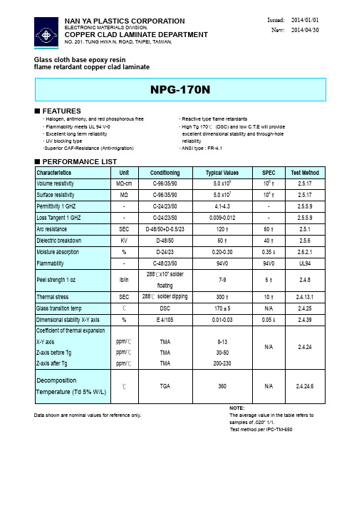
Glass cloth base epoxy resin flame retardant copper clad laminate
NPG-170N
FEATURES
Halogen, antimony, and red phosphorous free Flammability meets UL 94 V-0 Excellent long term reliability UV blocking type Superior CAF-Resistance (Anti-migration) Reactive type flame retardants High Tg 170℃ (DSC) and low C.T.E will provide excellent dimensional stability and through-hole reliability ANSI type : FR-4.1
Glass cloth base epoxy resin flame retardant prepreg
NPG-170NB
FEATURES
Halogen, antimony, and red phosphorous free Rheology of resin controlled to benefit the lamination of the boards. Modified phosphorous epoxy provides excellent heat and chemical resistance. Tg: 170±5℃
4.1-4.3 0.009-0.012 120 60 0.20-0.30 94V0 7-9 300 170 ± 5 0.01-0.03
迈克尔·艾迪森公司的C9MPT前端90型号炉膛说明书

Premier90THIS MODEL92.144041201005(9/2001)Model Number*9MPT050F12*9MPT075F12*9MPT100J16*9MPT125L20INPUT HIGH FIRE(BTUH)LOW FIRE(BTUH)50,00035,00075,00053,000100,00070,000125,00087,500HTG.CAP.HIGH FIRE(BTUH)LOW FIRE(BTUH)46,00036,20069,00048,80092,00064,400114,00080,500AFUE%(ICS)92.192.192.192.1 CSE%84.985.185.585.2 NOx(Ng/J)<40<40<40<40TEMP.RISE RANGE High Fire(o F)Low Fire(o F)35--6525--5540--7030--6040--7030--6040--7030--60VENT SIZE^2²--3²OD2²--3²OD3²OD3²OD VOLTS/PH/HZ115/60/1115/60/1115/60/1115/60/1 MIN./MAX.VOLTAGE97/13297/13297/13297/132 F.L.A. 5.37.59.212.0 TRANSFORMER(V.A.)40404040 GAS PIPE SIZE(IN.)1/21/21/21/2 COOLING CAP.(TONS) 3.0 3.0 4.0 5.0 FILTER SIZE(IN.)16X25X1(1)16X25X1(1)16X25X1(1)16X25X1(2) DIMENSIONS(in.)HEIGHT40404040 WIDTH X DEPTH191/8x29191/8x29223/4x29241/2x29 WEIGHT(Lbs.)150158182203^Vent size may vary depending on length,number of elbows,standard vent or direct vent.See Installation Instructions.Model Number*9MPT050F12*9MPT075F12*9MPT100J16*9MPT125L20 BLOWER TYPE AND SIZE11--811--811--1011--10 MOTOR H.P.(TYPE)1/2PSC1/2PSC1/2PSC3/4PSC MOTOR SPEEDS4444LOW826706823172010IN W C MEDIUM LOW108391711091910.10ESP IN.W.C.MEDIUM HIGH1301116315272127 HIGH1408136818502315LOW8046777951686 MEDIUM LOW105087510871881 .20ESP IN.W.C.MEDIUM HIGH1242112014822087 HIGH1347131917912268LOW7706367471644 MEDIUM LOW102884010561833 .30ESP IN.W.C.MEDIUM HIGH1195107614262024 HIGH1295128317202201LOW7355956771600 MEDIUM LOW98581210161777 .40ESP IN.W.C.MEDIUM HIGH1153103113821961 HIGH1237120216482131LOW6985466171533 MEDIUM LOW9527669701720 .50ESP IN.W.C.MEDIUM HIGH109398713171891 HIGH1183114815752029LOW6574905441494 MEDIUM LOW9097028541647 .60ESP IN.W.C.MEDIUM HIGH104088912451804 HIGH1118107714851948LOW------------------1413 MEDIUM LOW8636307631571 .70ESP IN.W.C.MEDIUM HIGH93582111541708 HIGH105398914011820 *Denotes Brand(T,H or C)SPECIFICATIONS SUBJECT TO CHANGE WITHOUT NOTICESPECIFICATIONS SUBJECT TO CHANGE WITHOUT NOTICE^Must be ordered from Service Parts *Denotes Brand (T,H or C)*9M PT075F12A1Brand Identifier Engineering Rev.*=Brand Denotes minor changesMarketing Digit Model IdentifierDenotes minor change8=Non--Condensing,80+%Gas Furnace Cooling Airflow 9=Condensing,90+%Gas Furnace 08=800CFM 12=1200CFM Installation Configuration 14=1400CFM UP =Upflow DN =DownflowUH =Upflow/Horizontal16=1600CFM HZ =HorizontalDH =Downflow/Horizontal20=2000CFM MP =Multiposition,Up/Down/Horizontal Cabinet Width Major Design Feature B =15.5²Wide1=One (Single)Pipe N =Single Stage F =19.1²Wide 2=Two Pipe P =PVC Vent J =22.8²Wide D =1or 2Pipe T =Two Stage L =24.5²WideL =Low NOxV =Variable SpeedInput (Nominal MBTUH)Model Number DescriptionUsed With Models1011787^Gas Conversion Kits (2--Stage)--LP (Propane)to natural gas conversion kit.Allows field conversion to natural gas.*9MPT 1011789^Gas Conversion Kits (2--Stage)--Natural gas to LP (propane)conversion Kit (includes LP high altitude kit).Allows field conversion to LP (propane)gas.*9MPTNAHA001PS 1009522^LP Low Pressure Switch --For detecting low line pressure.Opens at 6.5²W.C.(included in NAHF002LP)All LP *9MPT ModelsNAHA001FF Filter Kits --External filter frame.16²x 25²Side Return (All Furnaces)Bottom Return (All 19F d NAHA001FP External filter frame.16²x 25²(Bulk Pack Kit --Qty 10)()(“F”1/8²Furnaces under 1650CFM)NAHA002FF Filter Kits --Bottom return filter frame kit 20²x 25²(All “J”223/²Furnaces)NAHA002FP Bottom return filter frame kit 20²x 25²(Bulk Pack Kit --Qty 10)(4)NAHA003FF Filter Kits --Bottom or side return filter frame kit 14²x 25².(All “B”151/²Furnaces)NAHA003FP Bottom or side return filter frame kit 14²x 25²(Bulk Pack Kit --Qty 10)(2)NAHA001TKDuct Standoff Filter Kit.To adapt 20²x 25²filter for single side return.Side Return (All single return applications with1650CFM or greater)Bottom Return (All “F”191/8²Furnaces under1650CFM)NAHA001NK612833^Condensate neutralizer kit --for condensing gas furnaces All *9MPT Furnaces If RequiredNAHA036VA Blower Upgrade Kit --Variable speed blower upgrade (consists *9MPT050NAHA042VA pg p pg (of blower motor and electronics for 2--stage furnaces ONLY),*9MPT075NAHA060VA *9MPT100/125NAHH002SB Combustible Floor Subbase --Furnace ONLY:All 191/4²wide furnace models *9MPT050/075NAHH003SB Combustible Floor Subbase --Furnace ONLY:All 223/4²wide furnace models*9MPT100NAHH010SB Combustible Floor Subbase --Furnace ONLY:All 241/2²wide furnace models*9MPT125NAHH005SB Subbase --Furnacew/191/4²casedcoil*9MPT050/075Counterflow furnace w/191/4²cased coil NAHH006SB Subbase --Furnace w/223/4²cased coil *9MPT100Counterflow furnace w/223/4²cased coilNAHH009SB Subbase --Furnace w/241/2²cased coil*9MPT125NAHA001CV 1011129^3²Concentric vent kit --allows single wall penetration for 2pipe direct vent applications (90+).*9MPT100/125NAHA002CV 2²Concentric vent kit allows --single wall penetration for 2pipe direct vent applications (90+).*9MPT050/075NAHA001CACoil Adapter for Downflow FurnacesAll Downflow ModelsSPECIFICATIONS SUBJECT TO CHANGE WITHOUT NOTICE。
法兰克系统指令

Fanuc系统G代码表G码群功能 ★G00 01 定位G01 直线插补G02 顺时针圆弧插补/螺旋线插补G03 逆时针圆弧插补/螺旋线插补G04 00 暂停, 确实停止G05 高速循环加工G07.1(G107) 圆柱插补G09 确实停止G10 数据设定G11 数据设定取消G12.1(G112) 25 极坐标插补模式G13.1(G113) 极坐标插补模式取消★G15 17 极坐标指令取消G16 极坐标指令★G17 02 选择XpYp平面Xp:X轴或平行X轴 Yp:Y轴或平行Y轴 Zp:Z轴或平行Z轴 G18 选择ZpXp平面G19 选择YpZp平面G20 06 英制输入G21 工致输入★G22 04 存储行程检查开G23 存储行程检查关G27 00 原点返回检查G28 原点返回G29 从参考位置返回G30 第二,三,四原点返回G30.1 浮动原点返回G31 跳跃功能G33 01 螺纹切削G37 00 自动刀具长度测量G39 圆弧插补转角偏移量★G40 07 刀具半径补正取消G41 刀具半径左补正G42 刀具半径右补正★G40.1(G150) 19 通常方向控制取消模式 G41.1(G151) 通常方向控制左边开 G42.1(G152) 通常方向控制右边开G43 08 刀具长度正向补正G44 刀具长度负向补正G45 00 刀具偏移量增加G46 刀具偏移量缩小G47 刀具偏移量双倍增加G48 刀具偏移量双倍缩小★G49 08 刀具长度补正取消★G50 11 比例取消 G51 比例★G50.1 18 可编程镜像取消G51.1 可编程镜像G52 00 局部坐标系设定G53 机械坐标系★G54 14 工件坐标系1G54.1 附加工件坐标系G55 工件坐标系2G56 工件坐标系3G57 工件坐标系4G58 工件坐标系5G59 工件坐标系6G60 00 单向定位G61 15 停止检查模式G62 自动转角超弛G63 攻牙模式★G64 切削模式G65 00 巨指令呼叫G66 12 模态巨指令呼叫★G67 模态巨指令呼叫取消G68 16 坐标系旋转★G69 坐标系旋转取消G73 09 啄进钻孔循环G74 左螺纹攻牙循环G76 09 精镗孔循环★G80 09 固定循环取消/外部操作功能取消G81 钻孔循环G82 钻孔或反镗孔循环G83 啄进钻孔循环G84 攻牙循环G85 镗孔循环G86 镗孔循环G87 反镗孔循环G88 镗孔循环G89 镗孔循环★G90 03 绝对坐标指令G91 相对坐标指令G92 00 设定工件坐标系/或钳住主轴最高转速 ★G94 05 每分钟进给G95 每转进给G96 13 恒定表面速度控制★G97 恒定表面速度控制取消★G98 10 固定循环初始点返回G99 固定循环R点返回2 M代码M代码功能M00 程序停止M01 条件程序停止M02 程序结束M03 主轴正转M04 主轴反转M05 主轴停止M06 刀具交换M08 冷却开M09 冷却关M18 主轴定向解除M19 主轴定向M29 刚性攻丝M30 程序结束并返回程序头M33 主轴定向M98 调用子程序M99 子程序结束返回/重复执行F进给速度(每转进给)(每分进给)Q在G73 G83中表示深孔加工循环的每次切入量,在G76 G87中表示偏移量。
Victron Energy GX GSM 2G 3G 模块说明书

GX GSM manual1. Introduction1.1 Product descriptionThe GX GSM is an accessory for GX-devices. It is a cellular 2G and 3G modem; providing a mobile internet for the system and connection to Victron Remote Management (VRM) portal.It requires a SIM card of the Mini-SIM format; and connects to the GX-device with an included 1m USB cable.See also the GX GSM Product Page.Video explaining how to connect using LAN, WiFi, and the GX GSM:Video1.2 Antennas and accessoriesGSM: A small indoor GSM antenna is included. As an option we also sell an outdoor GSM antenna:GSM900100100 - Outdoor 2G and 3G GSM Antenna for GX GSMGPS: The unit has a built-in GPS receiver. An antenna is not included; to use the GPS received; purchase the GPS Antenna.GSM900200100 - Active GPS Antenna for GX GSMSee bottom of this manual for photos and specs of both antennas.1.3 CompatibilityThe GX GSM can be used with any of the GX Devices.The GX GSM requires Venus OS v2.22 or newer to be installed on the GX Device.1.4 When to use a mobile router insteadThe GX GSM provides an internet connection for the GX-device only. There is no option to share the internet to laptops, phones, or other devices.For installations where more devices need internet, such as a yacht or RV, consider installing a mobile router instead. More information here.2. InstallationMount the device and connect the antenna. Consider using the outdoor antenna when installing the GX GSM in a closed metal enclosure.Insert the SIM card. You will need to eject the SIM card tray with a pen or other pointy object. Be aware that the SIM card tray sits slightly recessed inside the unit. Be sure to push it all the way in.Connect the GX GSM to the GX-device with the supplied USB cable. Use a USB hub if all USB sockets are already in use.Connect DC power supply (8 to 70 VDC). A 1.4M wire is included, with M10 lugs and an inline fuse.After power-up, the blue LED will be solid blue. Next, once it has registered on a network, it will start blinking slowly. Finally, when it has established the internet connection, it will be blinking fast.3. ConfigurationWhen using a SIM card with its SIM-pin security disabled, the system will work without furtherconfiguration.Setting a SIM pin helps reducing the risk of the SIM card being stolen and used. Use a mobile phone to set the SIM pin, and there after configure it on the GX-device.Settings → GSM modem → PIN codeSome mobile networks require manual configuration of an APN specially when roaming. Contact your operator.APN name can be configured in Settings → GSM Modem → APN.4. GPSWhen the optional antenna is added; the position will be visible like this:Also the position is sent to the VRM Portal.5. StatusStatus BarGSM modem status can be checked at a glance by looking at the status bar.Icon DetailsGSM modem is connected to network, but not to the internet (no data connection).Either on purpose, because an ethernet or WiFi connection is available.GSM modem is properly configured, the 3G/E/etc icon reflects that the GSM modem internetconnection is in use.WiFi is available and its internet connection is in use. WiFi has priority over GSM.SIM PIN code is required.Roaming, only informative. To use internet connection while roaming it needs to be enabledinSettings → GSM modem → Allow roaming.SIM StatusStatus DescriptionReady SIM card is installed properly and registered to the networkSIM not inserted SIM card is missing or not inserted properly. SIM tray might hang out a little.PIN required SIM card requires 4 digit PIN for unlock.PUK required SIM is locked due to wrong PIN inputs. 8 digit PUK is required to release the lock state.SIM failure SIM does not respond - might be brokenSIM busy SIM is in busy stateSIM wrong Type of SIM is not supportedExternal Link6. Trouble shootingThere are many reasons for modem internet connection to not work. Carefully go through each step of this trouble shooting guide. Make sure to start at the first step. When asking for help, make sure to mention each step taken and the result.Step Details1Power Check that the blue LED is either lit continuous or blinking2USB connection The modem must be connected to USB, and visible in the Settings → GSM modem menu3Simcard status Check the SIM Status in the menu, it must show “Ready”. It will show “SIM not inserted”, or “PIN required”, or “PUK required” and more related errors when there is a problem. Please refer to the SIM Status list for details.4Signal strength 1 bar minimum for VRM logging, 2 or 3 bars are necessary for a working remote console5Carrier registration Check that a name of a Cellular provider is visible in the “Carrier” field. If it is not, check signal strength and otherwise contact your simcard provider and/or insert the simcard in a phone to double check its operation and subscription status.Step Details6Internet connection Verify that the Internet shows “Online”. Reasons for the system to not go“Online” whilst properly registered on the Network are:1) APN not configured, contact the network operator for details.2) The network is a different one than the home network (ie. roaming), and the setting to permit Roaming is disabled.3) Signal strength is strong enough to register on the network, but not to openthe data connection to the internet.7Connection to VRM Portal Verify that the VRM Portal menu shows a recent last connection time. See Settings → VRM Portal. For more details, see the VRM Connection troubleshooting chapter of the GX Manual .An outdoor antenna typically increases received signal by 15 dB to 25 dB.Note that Ethernet and WiFi connections have priority over the cellular connection. Even when the available Ethernet or WiFi connection does not have a good connection to the internet. There is no automatic detection in place which in such case switches over to the GX GSM. In more technicallanguage: when the cellular data connection is active, it is configured with a high routing metric. This way, the Linux kernel prioritises Ethernet or Wifi when these are available.This screenshot shows how all details look when everything is OK:7. Supported Frequencies (2G/3G)7.1 Available models & their supported frequency bandsGSM100100100 - GX GSM 900/2100:2G (GSM/GPRS/EDGE): 850/900/1800/1900 MHz (Quad-Band)3G (UMTS/HSPA+): 900/2100 MHz (Dual-Band)The used GSM module is a Simcom SIM5360E.GSM100200100 - GX GSM 850/1900:2G (GSM/GPRS/EDGE): 850/900/1800/1900 MHz (Quad-Band) - same between both models.3G (UMTS/HSPA+): 850/1900 MHz (Dual-Band)The used GSM module is the Simcom SIM5360A.Expected in first stock in 2020 Q3. And only short lived; since its successor, the GX LTE 4G,having 2G/3G and also 4G support is also coming soon.7.2 Notes regarding regional coverageUSA, Mexico, Canada and most of South America: 1900 MHz is the most common frequency for 3G, which is unsupported for the current version of GX GSM. But a second model is coming in 2020, see above.Australia: The 900MHz 3G frequency in remote areas is typically provided by Optus. Telstra's rural 3G network operates at 850MHz which is not supported with the current version of GX GSM. Both Telstra and Optus operate 2100Mhz networks in urban areas, and are supported.In case of uncertainty please double-check: GSM World Coverage Map8. Technical DataOuter dimensions (LxWxH)106×42.5×22 mm (Drawing)Voltage range8..70 VDCPower draw 2.5 W while 2G/3G data transfer <1.0 W in idle mode+0.4 W if GPS is enabledRecommended fuse size 500 mA @ 12 V 250 mA @ 24 V 100 mA @ 48 VWire gauge (power cable)0.5..1.5mm² / AWG 28..16 Antenna connector Type SMA FemaleSIM card Regular Mini SIM9. Accessory / AntennasOutdoor 2G and 3G GSM AntennaPart number GSM900100100Mounting option Screw MountCable Type Rg-316Cable Length0.25 mConnector SMA Male Straight Frequencies800/900/1800/1900/2100 MHz Signal Gain 3 dbiActive GPS AntennaPart number GSM900200100Mounting option MagnetCable Type Rg-174Cable Length 3.0 mConnector SMA Male Straight Frequency1575.42 MHzImpedance50 Ω。