DMC标准件手册讲解
DMC通用模具制造公差标准 20100223(增加了...

东风汽车模具有限公司DONGFENG MOTOR DIE & MOULD CO.LTDDMC通用模具制造公差标准DMC DIE MACHINING TOLERANCE STANDARD1 模具基准公差(三销孔,侧面基准,快速定位)3 导柱孔、导套孔公差H7孔直径尺寸 公差H7 位置尺寸公差A±0.0230 40,50 60,70,80 100,120(+0.021,0) (+0.025,0) (+0.030,0) (+0.035,0)适用范围: DMC1210,DMC1220,DMC1225直径尺寸公差H720,25 32,40,50(+0.021,0) (+0.025,0)63 (+0.030,0) 适用范围:DMC1255A至模具中心2 一般零件加工公差直径尺寸大于1小于315 大于315小于1000 大于1000 ±0.2 ±0.3 ±0.5公差H732,38,45(+0.025,0)55,65,78 (+0.030,0) 适用范围:DMC1260第 1 页,共 9 页东风汽车模具有限公司DONGFENG MOTOR DIE & MOULD CO.LTDDMC通用模具制造公差标准DMC DIE MACHINING TOLERANCE STANDARD4 导板公差基准面(包容面A)±0.02 间隙面(被包容B)减标准间隙±0.02 拉延翻整类导板间隙公差:0.1±0.02A B修边冲孔类端头导板间隙公差:0.06±0.02修边冲孔压料板导板间隙公差:0.15±0.050.06±0.020.15±0.05第 2 页,共 9 页东风汽车模具有限公司DONGFENG MOTOR DIE & MOULD CO.LTDDMC通用模具制造公差标准DMC DIE MACHINING TOLERANCE STANDARD5 拉延压料圈与凸模沿周间隙:3mm6 修边翻边压料板与镶块间隙:0.5mm8 斜楔冲孔压料板与凸模间隙 7 斜楔修边翻边压料板与镶块间隙:0.5mm第 3 页,共 9 页东风汽车模具有限公司DONGFENG MOTOR DIE & MOULD CO.LTDDMC通用模具制造公差标准DMC DIE MACHINING TOLERANCE STANDARD9 孔公差(凸模,凹模,柱销,弹性顶料器,侧销)凸模、凹模、柱销位置尺寸公差 A±0.02A±0.02凸模、凹模与固定板配合H6/m5, H6/g5,H6/n5 孔直径D4,5,6 8,10 13,16 20,22,25 32,38,40,45,50 56,63,71A±0.02 6 D 8,10柱销H7/m6销孔直径D公差H7 +0.012~0 +0.015~0 +0.018~0 +0.021~0 +0.025~0D公差H6(+0.008,0) (+0.009,0) (+0.011,0) (+0.013,0) (+0.016,0) (+0.019,0)12,16 20,25,30 40,50适用范围:DMC4110,DMC4115,DMC4120 DMC4130,DMC4140,DMC4150 DMC4160,DMC4170,DMC4180 DMC4510,DMC4520,DMC4530 DMC4540,DMC4550 DMC4580,DMC4590弹性顶料器DD+0.03 0第 4 页,共 9 页东风汽车模具有限公司DONGFENG MOTOR DIE & MOULD CO.LTDDMC通用模具制造公差标准DMC DIE MACHINING TOLERANCE STANDARD侧销H8/f7孔直径(D) 22 32,42公差H8 (+0.033,0) (+0.039,0)52,62 (+0.046,0) 适用范围:DMC1410,DMC1420D H8/f7第 5 页,共 9 页东风汽车模具有限公司DONGFENG MOTOR DIE & MOULD CO.LTDDMC通用模具制造公差标准DMC DIE MACHINING TOLERANCE STANDARD10 键槽公差10.1 定位键槽 键槽尺寸W 20,25,28 32 10.3 公差H9 (+0.052,0) (+0.062,0) 支承键槽公差要求B0 -0.1(键槽距离模具中心尺寸公差)适用范围:DMC1510A+0.1 0(部件距离模具中心尺寸公差)W H9/h910.2上下底板中心键槽W0+0.1此支承键(配键)可 以磨配,保证装配!第 6 页,共 9 页东风汽车模具有限公司DONGFENG MOTOR DIE & MOULD CO.LTDDMC通用模具制造公差标准DMC DIE MACHINING TOLERANCE STANDARD11 斜楔工作部分配合公差A±0.03 间隙0.04± 0.02 D-0.04±0.01 C±0.02 ±0.05 ±0.10.04±0.02 间隙B-0.04±0.01±0.1第 7 页,共 9 页东风汽车模具有限公司DONGFENG MOTOR DIE & MOULD CO.LTDDMC通用模具制造公差标准DMC DIE MACHINING TOLERANCE STANDARD12 固定板方孔、槽及底板窝座公差名义尺寸 <=50 >50-150 >150-260 >260-500 >500 尺寸偏差 +0.10 ±0.10 ±0.15 ±0.18 ±0.2014 压板槽位置公差13 模具闭合高度(SH)公差(长+宽)尺寸 公差15 凸模凹模的制造公差名义尺寸 <=18 >18-30 >30-80 >80-120 -0.025 -0.030 -0.035 -0.040 -0.050 凸模偏差 -0.020 凹偏差 +0.020 +0.025 +0.030 +0.035 +0.040 +0.045 +0.050 +0.060 +0.070小于1200 1200-3500 大于3500+1 +2 +5-3 -6 -7联合安装的模具,设计按照下面的方法实施: ①一套模具按照名义安装高度加工,一套模具上模留5mm加工 量,将来铣配闭合高度。
CRT-DMC300A手册1004

目录目录DMC300A三轴运动控制器 ..........................................................................................................1 第一部分 概述 ....................................................................................................................1 第二部分 控制器使用说明 ................................................................................................2 2.1 硬件说明............................................................................................................2 2.2 操作说明............................................................................................................5 2.3 软件说明............................................................................................................9 第三部分 Motion300A使用说明....................................................................................26 3.1 关于软件名称(Motion300A) ...................................................................26 3.2 安装到本地....................................................................................................26 3.3 Motion300A 的编辑环境使用说明 .............................................................26 3.4 编程操作........................................................................................................26 第四部分 编程实例 ........................................................................................................32 4.1 PC编程实例....................................................................................................32 4.2 控制器手动代码编程输入............................................................................35 附 录 ........................................................................................................................................38 1、 RS232 简单无硬件握手通信线缆制作........................................................38 2、 名词解释........................................................................................................38 3、 常见问题解答................................................................................................40-I-DMC300A 三轴运动控制器DMC300A 三轴运动控制器第一部分 概述DMC300A 非常感谢您使用 DMC300A 步进电机运动控制器。
dmc1000软件手册
第 1 页 共 53 页第一章 概述本手册主要是向你介绍DMC1000运动控制卡软件方面的内容,共分为八章;第一章为概述;第二章介绍驱动软件的安装;第二章介绍测试软件<Moton1000>的安装和使用;第四章介绍运动函数在windows下的调用;第五章为运动函数列表;第六章函数详解;第七章将向你介绍使用DMC1000控制卡的编程技术与技巧;第八章向你介在VB和VC两种编译下的一个编程实例(附源代码);附录A为DMC1000控制卡在使用过程中,经常遇到的一些问题及其解决方法。
从第二章到第八章,我们将从安装使用,直到如何进行编写程式,逐个环节地进行了介绍。
即使你是一位新手,也不必因为没有使用过这dmc1000控制卡而束手无策。
只要你按这个手册的介绍,逐步进行,便可收到事半功倍的效果。
我们为DMC1000控制卡提供了三类配套软件,其一是:测试软件(Motion1000);其二是:DMC1000控制卡的驱动软件;其三是:运动函数库;所有这些软件都被放置在随板卡符送的光盘的相应目录中。
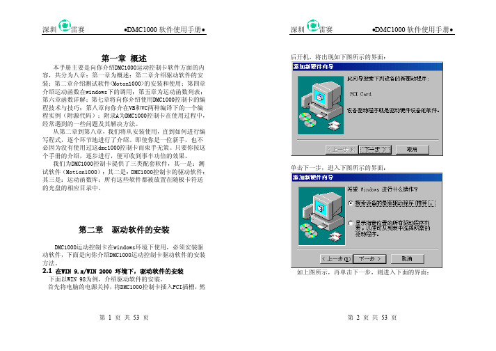
第二章 驱动软件的安装DMC1000运动控制卡在windows环境下使用,必须安装驱动软件,下面是向你介绍DMC1000运动控制卡驱动软件的安装方法。
2.1 在WIN 9.x/WIN 2000 环境下,驱动软件的安装 下面以WIN 98为例,介绍驱动软件的安装。
首先将电脑的电源关掉,将DMC1000控制卡插入PCI插槽,然第 2 页 共 53 页后开机,将出现如下图所示的界面:单击下一步,进入下图所示的界面:如上图所示,再单击下一步,则进入下面的界面:第 3 页 共 53 页在这里,假设G 盘为光盘,按上图输入“g:\dmc1000\windows 9.x\driver ”路径,或者选择“浏览”来寻找该路径,然后单击一步。
(通常DMC1000控制卡的驱动程式被放置在配套光盘的该目录下)第 4 页 共 53 页如上图所示,选择“下一步”,即可完成驱动程式的安装。
dmc小写操作说明

dmc小写操作说明一、引言在数字化时代,大数据分析和管理成为了企业和组织的一项重要任务。
DMC(Data Management Console)作为一种数据管理工具,为用户提供了便捷的数据处理和分析功能。
本文将详细介绍DMC 的小写操作方法,使用户能够更好地利用DMC进行数据管理和分析工作。
二、登录DMC1. 打开浏览器,在地址栏中输入DMC的网址。
2. 进入登录界面后,输入正确的用户名和密码。
3. 点击登录按钮,等待系统验证身份。
三、数据导入1. 在DMC的主界面上,点击“数据导入”按钮。
2. 选择需要导入的数据文件,并指定导入的数据格式。
3. 点击“导入”按钮,等待数据导入完成。
四、数据查询1. 在DMC的主界面上,点击“数据查询”按钮。
2. 在查询条件中输入需要查询的关键词。
3. 点击“查询”按钮,等待查询结果显示。
五、数据清洗1. 在DMC的主界面上,点击“数据清洗”按钮。
2. 选择需要清洗的数据表格。
3. 根据清洗需求,选择相应的清洗操作,如删除重复数据、填充缺失值等。
4. 点击“执行”按钮,等待清洗操作完成。
六、数据分析1. 在DMC的主界面上,点击“数据分析”按钮。
2. 选择需要分析的数据表格。
3. 根据分析需求,选择相应的分析方法,如统计分析、时间序列分析等。
4. 点击“执行”按钮,等待分析结果显示。
七、数据可视化1. 在DMC的主界面上,点击“数据可视化”按钮。
2. 选择需要可视化的数据表格。
3. 根据可视化需求,选择合适的图表类型,如柱状图、折线图等。
4. 调整图表样式和布局,使其更加直观和易于理解。
5. 点击“生成”按钮,等待可视化结果显示。
八、数据导出1. 在DMC的主界面上,点击“数据导出”按钮。
2. 选择需要导出的数据表格。
3. 根据导出需求,选择合适的导出格式,如CSV、Excel等。
4. 指定导出文件的保存路径和文件名。
5. 点击“导出”按钮,等待导出完成。
九、数据备份与恢复1. 在DMC的主界面上,点击“数据备份与恢复”按钮。
汽车模具标准件手册
汽车模具标准件手册随着汽车工业的迅速发展,汽车模具在汽车制造过程中起着至关重要的作用。
汽车模具标准件是指按照一定的尺寸和规格制作的,可以在多个汽车模具上通用的零部件。
具备标准件的模具可以提高生产效率、降低生产成本和提高产品质量。
本手册旨在介绍一些常见的汽车模具标准件,以便于模具制造商和使用者更好地了解和选择适合的模具标准件。
一、螺纹标准件螺纹标准件是模具中常用的连接件,可用于连接模具的各个部分。
常见的螺纹标准件包括螺栓、螺母、垫圈等。
这些标准件按照国际标准制作,能够确保其尺寸和质量的一致性。
螺纹标准件的选择应根据实际需要确定其型号和尺寸。
二、定位标准件定位标准件用于确保模具的定位精度,能够有效地提高模具的装配准确度和使用寿命。
常见的定位标准件包括销钉、销子和台阶销等。
这些标准件具有统一的尺寸和形状要求,可适用于多种模具,提高了模具的通用性和互换性。
三、导向标准件导向标准件用于引导和支撑模具的移动过程,能够提高模具的工作稳定性和精度。
常见的导向标准件包括导柱、导套和滑块等。
这些标准件具有标准的外径和长度,能够确保模具的准确定位和运动轨迹。
四、压紧标准件压紧标准件用于固定和夹紧模具的部件,能够确保模具的装配精度和工作稳定性。
常见的压紧标准件包括压簧、垫片和卡箍等。
这些标准件具有一定的弹性和固定能力,能够满足不同模具的压紧需求。
五、排气标准件排气标准件用于排除模具中的气体和气泡,避免产品出现缺陷和变形。
常见的排气标准件包括排气筒、排气塞和排气口等。
这些标准件具有一定的孔径和结构设计,能够有效地实现排气功能。
六、冷却标准件冷却标准件用于散热和降温,能够提高模具的热平衡和延长使用寿命。
常见的冷却标准件包括冷却水口、冷却板和冷却芯等。
这些标准件具有一定的冷却效果和通道设计,能够满足模具的散热需求。
七、定型标准件定型标准件用于保持和限制模具中部件的形状和位置,能够提高模具的加工精度和产品质量。
常见的定型标准件包括固定板、定位块和挡料等。
DMC-2143参数说明

产品优点︰●Ethernet: 10base-T , RS232 高达 19.2kb●Ethernet支援多组主控装置及多组受控装置, 并支援TCP/IP,UDP 及ModBus协定●任一轴均可控制步进或伺服马达●编码器回馈频率: 12MHz ; 步进输出频率: 3MHz ( 脉冲及方向 )●PID补偿与速度/加速度前馈功能, 积分极限, 陷波滤波器, 低通滤波器●运动模式: 速度控制, 点对点定位, 线性及圆弧补间, 电子齿轮&凸轮, 连续路径运动.特色: 椭圆轴比例设定, 过弯减速, 无限线段进给, 超驰进给( feedrate override)●提供200多个指令, 可执行条件式;事件驱动●程式, 变数, 阵列, 非挥发性记忆, 可同时执行8组程式●双encoders回馈, 原点复归, 正负极限●可程式I/O:1~4轴使用8组TTL输入点及8组输出点5~8轴使用16组TTL输入点及16组输出点●可选配8 analog input and 40 digital I/O ( DB-28040 )●各轴均配置高速位置捕捉及位置比较输出功能●底盘按装选项: DIN-Rail●输入电压+5V, ±12V DC●使用96-pin DIN连接器直接与端子台结合(不需缆线),且端子台提供D型接头●支援Linux , DOS , 所有 Windows作业系统产品规格︰名称马达控制卡 - DMC21x3品牌Galil DMC-21x3 经济型以太网控制器及驱动器针对低成本、少接线的多轴运动多轴驱动直接与控制器相连,无需连接线缆提供高速以太网通讯的全部优势控制器处理所有运动控制工作,减轻PC编程的复杂性与工作负担成本远低于多个独立的单轴控制器和驱动器可驱动高达500W功率的步进电机,有刷及无刷伺服电机低成本、小空间应用的理想选择Galil 低成本的多轴控制器和驱动器组合Galil独特的经济型以太网控制驱动器产品DMC-21x3,以低成本,独立于PC的紧凑封装提供了多轴控制的优秀性能,并且减少了控制器与驱动器之间的接线。
Festo DNCM-32-1 2 杆位驱动器说明书
Value
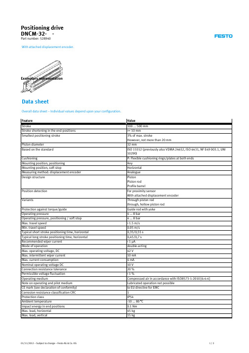
100 ... 500 mm >= 10 mm 3% of max. stroke However, not more than 20 mm 32 mm ISO 15552 (previously also VDMA 24652, ISO 6431, NF E49 003.1, UNI 10290)
Materials information for piston rod Material information, plug housing Materials information for cylinder barrel
Value
3 kg 3 kg 415 N 483 N 198 g 51 g 650 g 11 g <= 0.01 mm Analogue <= 5 ppm/K < 0,1 mm +/- 2 mm 4-pin with accessories G1/8 Wrought Aluminium alloy NBR TPE-U(PU) High alloy steel PPE reinforced Wrought Aluminium alloy
Position detection
Variants
Protection against torque/guide Operating pressure Operating pressure, positioning / soft stop Max. travel speed Min. travel speed Typical short stroke positioning time, horizontal Typical long stroke positioning time, horizontal Recommended wiper current Mode of operation Max. operating voltage, DC Max. intermittent wiper current Max. current consumption Nominal operating voltage DC Connection resistance tolerance Permissible voltage fluctuation Operating medium Note on operating and pilot medium CE mark (see declaration of conformity) Corrosion resistance classification CRC Protection class Ambient temperature Impact energy in end positions Max. load, horizontal Max. load, vertical
机床手册-安全手册-DMC64V

所有者和操作者应注意将操作手册总放在身 旁。若有疑问,查阅操作手册中的有关章节, 而不要胡乱操作机床。
1-4
DECKEL MAHO
基本规定
机床条件 和周围环境
所有者保证除非机床处于完好的工作状态, 否则不允许使用机床。所有者有责任检查机 床总体状态并注意在启动机床之前消除可能 的缺陷。 机床上所有安全说明和危险警告必须完整并 且清晰可辨。 对机床、操作特性或环境条件的任何改变必 须立即报告给所有者。若涉及到任何安全危 险,则必须立即停止机床并且固定总开关, 以防意外或未经授权启动机床。
谁可操 作机床?
未经合格培训——须通过职业培训机构或在 DECKEL MAHO 的培训中心获得内部培训 (不管培训多么短暂),否则不允许任何人操 作机床,。
所有者和操作者必须确保不准未经专门培训 的人操作机床。
DECKEL MAHO
1-3
基本规定
操 作 手 册 对 与搬运、安装、调试、维护和修理机床有关的 你所做的任 所有工作只能由经过专门培训和胜任特定任 何 事 情 都 具 务的人员执行。在工作期间,这些人员必须遵 有重要意义 守操作手册中提供的指示,并遵守所有适用的
- 锪孔 - 钻和镗 - 攻丝和攻螺纹 - 仿形钻 - 钻非圆柱孔
所有者和操作者应避免机床的任何误用。厂 家对于预期用途范围以外的机床的使用概不 负责。此外,这种误用可能涉及不可预见的 人员生命和四肢危险和机床或所有者其他资 本价值破坏的危险。
1-6
DECKEL MAHO
基本规定
附件
DECKEL MAHO 提供了许多特殊附件和选 配设备,目的是扩大 DECKEL MAHO 机床 的应用范围。
不要将任何东西放到运动的机床部件区域, 即便短暂地存放也不可以。如果最坏的事情 发生,则您可能被缠住和受伤。
dmc done 条件判定

dmc done 条件判定DMC(Done 条件判定)是一种质量管理方法,用于确定任务是否已完成。
在软件开发中,DMC 是一种常见的测试方法,通过对软件系统的功能和性能进行测试,判断系统是否满足预期的标准和要求。
本文将介绍DMC 的定义、作用以及实施步骤,并探讨其在软件开发中的应用。
DMC 是一个缩写词,其中D 代表“Done”(完成),M 代表“Must”(必要条件),C 代表“Check”(检查)。
DMC 的主要目的是确保软件开发过程中的任务和功能均按照预期完成,并通过检查验证其正确性和可用性。
在软件开发过程中,DMC 的实施步骤如下:1. 定义任务:首先,需要明确任务的目标和要求。
任务可以是软件功能的实现、性能优化、Bug 修复等。
针对每个任务,需要明确其完成的标准和要求。
2. 制定必要条件:根据任务的要求,确定完成任务所必需的条件。
这些条件可能包括软件环境的配置、必要的资源和数据等。
3. 进行检查:在任务完成后,进行检查以验证任务的完成情况。
检查可以通过软件测试、代码审查等方式进行。
检查的目的是检验任务是否按照预期完成,是否满足预定的标准和要求。
DMC 的应用有助于提高软件开发的质量和效率。
通过明确任务的完成标准和要求,可以避免任务的不完整或错误。
通过制定必要条件,可以确保任务的顺利进行,并减少潜在的问题和风险。
通过检查,可以及时发现并纠正任务中存在的问题,确保软件的正确性和可用性。
DMC 在软件开发中的应用非常广泛。
它可以应用于各个阶段和环节,包括需求分析、设计、编码、测试等。
在需求分析阶段,可以通过DMC明确需求的完成标准和要求,确保需求的准确性和完整性。
在设计和编码阶段,可以通过DMC制定开发任务和完成标准,确保软件的正确实现。
在测试阶段,可以通过DMC进行功能测试和性能测试,确保软件的质量和性能。
DMC 是一种有效的质量管理方法,可以帮助软件开发团队确保任务的完成和软件的质量。
通过明确任务的完成标准和要求,制定必要条件,并进行检查,可以提高软件开发的质量和效率。
设备管理控制台(DMC)配置使用手册_08新版_V3.2

设备管理控制台(DMC)配置使用手册Hangzhou H3C Technologies Co., Ltd.杭州华三通信技术有限公司/solutionAll rights reserved版权所有侵权必究声明Copyright © 2008 杭州华三通信技术有限公司及其许可者版权所有,保留一切权利。
非经本公司书面许可,任何单位和个人不得擅自摘抄、复制本书内容的部分或全部,并不得以任何形式传播。
H3C、Aolynk、、IRF、H3Care、、Neocean、、TOP G、SecEngine、SecPath、COMWARE、VVG、V2G、V n G、PSPT、NetPilot、XGbus 均为杭州华三通信技术有限公司的商标。
对于本手册中出现的其它公司的商标、产品标识及商品名称,由各自权利人拥有。
修订记录目录第1章设备管理控制台概述 (8)1.1 设备管理控制台的主要功能 (8)1.2 DMC的优点 (10)1.3 DMC配置举例 (10)1.3.1 组网描述 (10)1.3.2 组网图 (11)1.3.3 配置步骤 (11)1.3.4 验证 (12)1.3.5 注意事项 (12)1.4 DMC在网络实验室解决方案中的应用 (12)第2章 DMC硬件配置 (14)2.1 主机特性 (14)2.1.1 系统规格 (14)2.1.2 主机外观 (15)2.2 8ASE/16ASE模块 (15)2.2.1 模块简介 (15)2.2.2 接口属性 (16)2.2.3 接口指示灯 (16)2.2.4 接口连接电缆 (17)第3章 DMC软件配置 (20)3.1 文件的获取和上传 (20)3.1.1 http.zip文件的获取 (20)3.1.2 http.zip文件的上传 (20)3.2 进入系统视图 (22)3.3 Telnet重定向配置 (22)3.3.1 TTY编号规则 (22)3.3.2 配置异步接口为流模式 (23)3.3.3 启动Telnet重定向功能 (24)3.3.4 配置监听端口 (24)3.3.5 配置用户界面其他相关参数 (25)3.3.6 断开Telnet重定向连接 (25)3.4 DMC功能模块配置 (26)3.4.1 用户管理 (26)3.4.2 DMC模块相关命令 (28)3.4.3 DMC配置文件 (29)3.4.4 正则表达式的使用 (31)3.5 DMC模块的Web接口 (32)3.5.1 登录DMC (32)3.5.2 浏览实验设备 (34)3.5.3 反向Telnet到实验设备 (35)3.5.4 管理实验设备 (35)3.5.5 清除设备配置 (38)3.5.6 重新检测相连设备 (39)3.5.7 退出登录 (39)3.5.8 Telnet到控制台 (39)3.5.9 关于我们 (40)第4章 FAQ (41)第5章附录 (43)插图目录图1-1 设备管理控制台在实验台中的位置 (8)图1-2 网络实验室组网示意图 (9)图1-3 DMC典型配置举例 (11)图1-4 网络实验室组网示意图 (13)图2-1 H3C AR 28-11前面板图 (15)图2-2 H3C AR 28-11后面板图 (15)图2-3 8ASE模块面板 (16)图2-4 16ASE模块面板 (17)图2-5 备份口电缆示意图 (17)图2-6 配置口电缆示意图 (18)图2-7 连接电缆线序 (18)图2-8 以太网电缆示意图 (18)图3-1 TFTP Server应用程序界面示意图 (21)图3-2 DMC用户登录页面 (33)图3-3 DMC浏览实验设备 (34)图3-4 DMC实验设备配置 (35)图3-5 DMC管理实验设备 (36)图3-6 DMC管理员登录页面 (37)图3-7 DMC管理员登录失败页面 (38)图3-8 DMC清除实验设备配置 (39)图3-9 Telnet到设备管理控制台(DMC) (40)图4-1 Web浏览器Telnet客户端配置页面 (41)表格目录表 2-1 H3C AR 28-10/28-11路由器系统说明表 (14)表 2-2 8ASE/16ASE模块接口属性 (16)表 3-1 配置步骤列表 (20)表 3-2 用TFTP下载文件 (21)表 3-3 进入系统视图 (22)表 3-4 配置异步接口为流模式 (23)表 3-5 建立Telnet重定向连接 (24)表 3-6 配置用户界面的相关选项 (24)表 3-7 配置用户界面的相关选项 (25)表 3-8 配置断开Telnet重定向连接 (25)表 3-9 配置登录用户界面的认证方式 (26)表 3-10 DMC模块相关操作命名 (28)表 3-11 dmc device-type show命令显示信息描述表 (28)表 3-12 正则表达式的元字符描述 (31)设备管理控制台配置使用手册关键词:DMC;网络实验室摘要:本文档详细描述了H3C网络实验室的实验设备管理控制台(DMC)设备的使用方法。
DMC电插头工具指南

Connector Tooling GuideDANIELSMANUFACTURING CORPORA TION®An ISO9001 and AS9100Registered Company© COPYRIGHT 2005 DANIELS MANUFACTURING CORPORATIONREV . 9Daniels tools have been utilized in military aircraft and aerospace programs for over 50 years (DMC founded in 1949).By continuously planning and adding to our product lines, we are now fulfilling the demands of other high technology fields such as computers, lasers, communications, and many other areas of electronic packaging.The people behind the DMC name are pleased to present our Connector Assembly Tools and Accessories on the pages that follow. We believe the application data which accompanies each section will answer your specific questions concerning tooling; however, we encourage you to contact us by telephone or fax for the personal services of our knowledgeable staff of application experts.CONTENTSImportant Facts About Crimping . . . . . . . . . . . . . . . . . . 1Tensile Test Systems . . . . . . . . . . . . . . . . . . . . . . . . . . . . 2MPT 500-A Heavy Duty Motorized Pull Tester . . . . . . . 4HPT -200 Hand Held Wire Crimp Pull Tester . . . . . . . . . 5Standard Adjustable Crimp Tool . . . . . . . . . . . . . . . . . . . 6M22520/1-01 (AF8)Miniature Adjustable Crimp Tools . . . . . . . . . . . . . . . . . 8M22520/2-01 (AFM8)M22520/7-01 (MH860)M22520/39-01 (39-000)Ultra Precision (MH800)Pneumatic Crimp Tools . . . . . . . . . . . . . . . . . . . . . . . . . 10(WA22)(WA22P)(WA27F)Specialty Pneumatic Tools . . . . . . . . . . . . . . . . . . . . . . 11First End Package Second End PackageLarge Gage Pneumatic Crimp Tools . . . . . . . . . . . . . . 12M22520/23-01 (WA23)Large Gage Contact Application Information . . . . . . . 13Technical Application Guide . . . . . . . . . . . . . . . . . . . . . 14Connector Illustration Contact Color Code (BIN)Wire StrippingM39029 Contact Quick Location ChartConnector/Assembly Tool Guide By Series . . . . . 16–44MIL-STD-1760 Connector Tooling . . . . . . . . . . . . . . . 27Circular Indent Crimp Tools . . . . . . . . . . . . . . . . . . . . . 45(MH801) (MH802) (MH803) (MH804)M22520/4-01 (GS100-1)M22520/31-01 (GS200-1)Coaxial Contact Tool Selection Guide . . . . . . . . . . . . . 46Open Frame Crimp Tools . . . . . . . . . . . . . . . . . . . . . . . 48M22520/5-01 (HX4)M22520/10-01 (HX3)Pneumatic Open Frame Tool . . . . . . . . . . . . . . . . . . . . 50Open Frame Operation, Dies, andEHCY Series Electric Tool . . . . . . . . . . . . . . . . . . . 51Pneumatic/Hydraulic PortableCrimp Tool Systems . . . . . . . . . . . . . . . . . . . . . . . . 52DMC Crimp Dies For A Full Rangeof Capabilities . . . . . . . . . . . . . . . . . . . . . . . . . . . . . 53Typical Die Configurations and ApplicationsR.F . Connectors Tool Selection Guide . . . . . . . . . . 54–65Hydrac Hydraulic Crimping Tools . . . . . . . . . . . . . 66–69Contact Retention Test Tools . . . . . . . . . . . . . . . . . . . . 70Installing and Removal Tools . . . . . . . . . . . . . . . . . 71–73MIL-I-81969Commercial Standard Hand Crimp Tools . . . . . . . . . . 74GMT232DCT4GMTHand-Held Pneumatic Wire Stripping Tool . . . . . . . . . 75(WSP 1630)EMI/RFI Band Application System . . . . . . . . . . . . . . . . 76Connector Service Maintenance/Support Kits . . . . . . 80Limited Warranty . . . . . . . . . . . . . . . . . . . . . . . . . . . . . . 81FOR WARRANTY & LIMITATION OF LIABILITY INFORMATION SEE PAGE 81DANIELS MANUFACTURING CORP .526 THORPE RD. • ORLANDO, FL 32824 U.S.A.PHONE 407/855-6161 • FAX 407-855-6884E-MAIL: DMC@ • CRIMPING: THEN AND NOW The first multi-pin connectors were terminated by soldering the conductor to non-removable contacts. However, high temperature applications andthe need for simple and reliable field service led to the introduction of connectors with removable contacts. These were crimped onto the con-ductor rather than being soldered.The first standard crimp tool developed to crimp these new con-tacts was introduced in the early sixties. MS3191-1, a military drawing, defined this tool and its accessories. The MS3191-1 utilized a four indent crimp pattern together with a positive stop locator which controlled the travel of the indenters (crimp depth).The MS3191-1 design was a compromise between simplicity of operation and crimp performance since the crimp depth for any given contact was not adjustable to accom-modate the differing diameters of the conductors to which it would be crimped. It was, however, suitable for the crimp connectors of that era.An improved tool design featuring independently adjustable crimp depths was soon introduced as MS3191-4. The MS3191-4 had an internal adjust-ment, totally independent of the loca-tor, which permitted the selection of seven separate crimp depths, allowing optimal crimping of conductors rang-ing from AWG 12 to 26 regardless of the wire barrel size of the contact.MS3191-4 also introduced the use of the double tipped indenter to produce an eight indent crimp pattern which has consistently achieved superior tensile pull off values.MS3191-4 introduced the concept of a turret head containing three loca-tors which could be used without separating any of them from the basic crimp tool.In 1969 two military specifications for crimp tools were developed to replace the existing military drawings. They were MIL-T-22520C (Navy) and MIL-T-83724 (USAF) which defined a standard size crimp tool similar to the MS3191-4, but with an expanded eight step crimp depth range. These specifications also defined a miniature crimp tool to crimp conductors as small as AWG 32.Both documents were combinedin 1971 into MIL-C-22520D. Allprevious military standards for crimptools were then cancelled includingthe MS3191.MIL-C-22520 (changed in 1996to MIL-DTL-22520) has since replacedmany other crimp tool documentsincluding: MS3198, MS22910,MS17776, MS28731, MS90388,MS14037, MS27437, MS27828,MS27832, MS55619, MS27426 andothers. This list includes specificationsfor indent crimp tools, terminal lugcrimp tools, pneumatic tools, coaxialcable crimp tools and connectorservice kits.The establishment of MIL-DTL-22520 was a milestone on the roadto crimp tool standardization. Itsdevelopment has eliminated the wasteand confusion which accompaniedthe overlapping applications of manydifferent “standard” crimp tools calledout by a deluge of unrelated militarydrawings.MIL-DTL-22520 established asingle specification which set forthperformance requirements for all crimptools to be used on military standardelectrical connectors.THE CRIMPING CONCEPTCrimping is a method of firmlyattaching a terminal or contact end toan electrical conductor by pressureforming or reshaping a metal barreltogether with the conductor. Theforming of a satisfactory crimpdepends on the correct combinationof conductor, crimp barrel and tool.When applied with a properlymatched tool, a union would beestablished which has both goodelectrical and mechanical charac-teristics. The tool will provide theserequirements consistently and reliablywith repeatability assured by qualitycycle controlled tooling. There areseveral common configurations ofcrimped joint; several examples areshown below.The electrical resistance of aproperly designed and controlledcrimped joint should be equal to, orless than, the resistance of an equalsection of wire. Specifications statethe requirements in terms of millivoltdrop at a designated current.The mechanical strength of acrimped joint and hence its pull-outforce (tensile strength), varies with thedeformation applied. Therefore, byproperly shaping the deformation ahigh pull-out force can be achieved,i.e. the crimp die of the tool deter-mines the crimp configuration anddeformation.The dies in the tool determine thecompleted crimp configuration whichis generally an element of contactand/or connector design. Some of thedesign considerations are: a) The typeof contact, its size, shape, materialand function, b) The type and size ofwires to be accommodated, c) Thetype of tooling into which the configu-ration must be built.© COPYRIGHT 2005 DANIELS MANUFACTURING CORPORATION © COPYRIGHT 2005 DANIELS MANUFACTURING CORPORATIONTHE DEPENDABLE A LPHA -TEST ™SYSTEMNow available from DMC is a line of Electronic Tensile Test Systems which may be used in conjunction with SPC Programs or other Quality Control disciplines in both OEM and maintenance applications. The elec-tronic digital readout displays are a fast and reliable source of test data,and in some models the data may be output to a printer or other RS232compatible devices.The rugged construction and theportable design of these test machines make any of them asuperior choice for on-site or laboratoryuse in an infinite variety of applications. The operation of the equipment is simple yet versatile, and DMC will customize the gripping jaws or other components to make test sample installation and removal an easy task.Models are available with output display readings in Pounds, Newtons,and/or Kilograms to conform with the requirements of the users system.Units are available for either 115 or 230 volt power input.It’s only natural that the company which supplies the best wire termina-tion tools and equipment would add the very best Digital Tensile Testers to further meet the demand for fewer sources and improved supportthrough a wider range of user needs.Also consult DMC for Model HPT -200 hand-held pull tester which blends the accuracy and rugged design of the Alphatron pull testersinto a portable battery powered unit.Featured is Model MPT -200A.Other models are listed on Page 3, 4 and 5.MODEL HPT -200 HAND-HELDPULL TESTER•.5% Accuracy (1/2 of 1%)•Portable Designs •Easy to Operate •SPC Compatible•Many Grips Available •Custom Applications Are No ProblemNow Available . . .ALPHA-TEST DATA LINKSOFTWARETo serve the data collection needs of your test labor in-process operations. Part No. 15-7010PAGE 2© COPYRIGHT 2005 DANIELS MANUFACTURING CORPORATIONMPT -500A Options:See page 4.MPT -200A Options:0-250 lb. Capacity 1 lb. Resolution • Universal Self-Tightening Cam-Type Lower Grip • Ring Terminal Lower Grip • Display Units in Kilograms • Display Units in Newtons • Lb/Kg Switching • Lb/Newtons Switching • 7.5–30″/min. Selectable Rates of Pull in 10 2.5″/min. Increments • Adjustable Set-point for Motor Stop at Pre-Set Force • RS232 Output.PT -100A Options:Extra-wide Cam Grips (.75 in. wide) • Ring Terminal Lower grip • 15 Position Slotted Lower Terminal Grip • Safety Cable Grips (Upper and Lower)PT -100 Options: Upper Self Tightening (PT -100A type) • Ring Terminal Lower Grip • Upper Assembly for Short Wires (.25 in. min.) • Spark Plug Lower Grip Assembly • 90°Plug Wire Upper Support Assembly.HPT -200 Options: See page 5.PAGE 3MANUALPULL TESTERS PT -100 & PT -100AMODEL PT -100A SHOWNHAND-HELD PORTABLE PULL TESTER MODEL HPT -200MOTORIZED PULL TESTERSMANUAL PULL TESTERSMPT -500AMPT -200APRECISION WIRECRIMP PULL TESTING FOR HIGH STRENGTH APPLICATIONS…The MPT -500A Motorized Pull Tester has a range from five pounds force to five hundred (2224.1N,226.8Kg). You can expect the same precision and dependability that has established all ALPHATRON ®testers as the first choice for wire harness builders and component suppliers throughout the industry. The 500pound capacity of this tester willextend the range of testing capabilities to size 4 Mil-Spec applications, and size 4/0 in commercial and automotive applications (Reference AS7928 and UL486 Respectively).The portable design (33 pounds,8″x10″x17″) and the rugged construc-tion (machined aluminum and steel)contribute to the versatility and reliability of the MPT -500A Pull Tester. A variety of options, including standard and custom grips for all types of wireterminations are available on this tester.The operation of the tester is simple and has automatic reset and auto-stop features incorporated into the design.The peak-hold digital display indicates the highest pull force that is measured by the accurate load cell/digital processor until the reset switch is pressed. This test value can be manually recorded, or can be inte-grated into a network database using the DMC Alpha-Test Data Link (ATDL)software, or other RS232 compatible data-point collection programs.The MPT -500A Wire Crimp Pull Tester completes the range of all digital precision ALPHATRON ®testers from DMC. Consult the factory for more specific information, and application verification.© COPYRIGHT 2005 DANIELS MANUFACTURING CORPORATIONPAGE 4Daniels Manufacturing Corporation introduces a portable tensile tester capable of pull testing wire crimps up to 200pounds (up to 10 AWG wire in most cases).THE LAB IS NOLONGER THE LIMIT…It is only natural that the company,which is known throughout the world for quality wire termination tools and equipment would add the very best portable tensile tester to meet your need for fewer sources and improved support through a wider range of capabilities. The HPT -200 hand held pull tester combines the accuracy and rugged design of the Alphatron pull testers into a portable battery powered unit. We follow that up with our expert factory service and calibration.The HPT -200 portable tester is an extension of the Alphatron Wire Crimp Pull Tester line of products, which include the PT -100, PT -100A, MPT -200A and MPT -500A. These testers perform pull-force measurements on wire terminations. The rugged con-struction and portable design of these test machines make any of them a superior choice for on-site or laborato-ry use.The lightweight Alphatron HPT -200 is a self-contained tester that extends your testing capability to the shop floor. You no longer have to wait for process samples to arrive in the QA Lab. Durable construction and a convenient carry case ensureprotection. The patented Low Stress tensioning mechanism makes the HPT -200 versatile and easy to use. A built in NIHM battery provides up to 14 hours use on a single charge and the Power Management Circuit allows use during charging.© COPYRIGHT 2005 DANIELS MANUFACTURING CORPORATIONPAGE 5SLOT DIMENSIONSize (in.)No.Size (in.).0319.25010.04711.23612.06313.21814.08015UPPER RANGE CRIMP TOOL AF8 M22520/1-01The DMC AF8 qualified toMIL-DTL-22520/1, has virtually limit-less application within the specified wire range of 12 through 26 AWG.Over a thousand turret heads are available to adapt the tool frame to your specific military or proprietary contact/wire combination. The 8impression crimp, which is standard in the AF8, assures absolute maxi-mum tensile strength with almost every closed barrel contact. In addi-tion, special indent configurations are available upon request.The precision ratchet controls cycling of the tool in both directions of handle movement. This assures the same accurate crimp every time. It’s like having a quality control inspector at every work station.Positive crimp depth is controlled by an 8 position selector knob conve-niently located on the tool frame. Theoperator simply dials the desired step for the wire being used. This setting can be secured by use of a locking pin or safety wire. The carefully engineered design achieves the absolute maxi-mum mechanical advantage; along with the tool’s light weight, operator fatigue is minimized.The AF8 measures 93⁄4″x 21⁄2″x 11⁄4″approximately and weighs 15 oz.For proper operation, the tool must be mated with one of the following optional accessories: a military standard or non-military turret head (TH-XXX Part No. Series), a military standard or non-military positioner (TP-XXX Part No. Series), or a universal head (Part No. UH2-5). This is done simply by orienting the head in the keyed posi-tion, and by tightening the hex socket screws provided as part of the head.A permanent dataplate is affixed to all turret heads and positioners. This plate lists specific contact part num-bers, the corresponding position color code (for 3 position turret heads), andsuggested selector depth settings for the wire size being used.The universal head is ideally suited for lab work and prototype production applications. This head is attached in the same manner as explained above.The selected contact is insertedthrough the entry hole on the opposite side of the tool frame from the head.The height adjusting screw is then rotated until the contact is in the proper position for crimping. Thescrew can be secured with the locknut provided. The wire sizes listed on the tool frame selector knob can be used as a reference starting point; however,some testing will be necessary todetermine the optimum selector setting for your contact/wire combination.Periodic gaging is recommended to insure accurate calibration. This can be done easily by setting the tool selector knob to position #4, and checking indenter closure with the M22520/3-1 “GO/NO-GO” gage (DMC part no. G125).© COPYRIGHT 2005 DANIELS MANUFACTURING CORPORATIONPAGE 6Other than keeping the unit clean and properly stored when not in service, no operator maintenance is required. DMC offers complete factory service by knowledgeable technicians within a reasonable turnaround plete instructions concerning the use, care and warranty are supplied with each tool. Additional copies are available on request.© COPYRIGHT 2005 DANIELS MANUFACTURING CORPORATION PAGE 7LOWER RANGE CRIMP TOOL AFM8 M22520/2-01Qualified to MIL-DTL-22520/2, the DMC AFM8 is designed for most of the miniature and sub-miniature con-nector types that are so widely used in all types of electronic systems.Originally developed for the Air Force,the AFM8 meets the need for a minia-ture tool accommodating wire sizes 20through 32 AWG.The AFM8 gives a Mil-Standard 8 impression crimp, which assures maximum tensile strength. The cycle controlled precision ratchet assures consistently accurate crimps every time. The tool frame has a built-in 8step selector knob for ease in dialing the correct crimp depth setting for the wire being used.Positioners adapt the tool frame to a particular application. The data plate on each positioner designates which contacts the positioner accommodates for its wire size and indicates selector position. Crimp depth is dialed on the8 step selector knob by merely raising the knob and rotating it to the proper position. The positioner is easily removed and changed.Periodic gaging is recommended to insure accurate calibration. This is easily accomplished with the M22520/3-1“GO/NO-GO” gage (DMC part no.G125) on SEL setting #8. The AFM8 is 6 3/4″in length and weighs approxi-mately 10 oz.Other than keeping the tool clean and properly stored when not in use,no operator maintenance is required.DMC’s complete factory service is available. Complete instructions con-cerning the use, care and warranty are supplied with each tool. Additional copies are available from the factory.© COPYRIGHT 2005 DANIELS MANUFACTURING CORPORATIONPAGE 8UL TRA PRECISION CRIMP TOOL (MODEL MH800)All DMC tools are designed and built to the highest standards of preci-sion and quality, but some applications call for more. One such case is minia-ture and sub-miniature contacts which have extremely thin wire barrel dimen-sions. The answer to this demand is the model MH800 Ultra Precision Crimp Tool which utilizes the same basic components as the Model MIDDLE RANGE CRIMPTOOL MH860 M22520/7-01Qualified to MIL-DTL-22520/7,the DMC MH860 is a recent additionto the military specification. It wasdeveloped to meet the demonstratedneed for supporting the majority ofelectrical systems with one versatilecrimp tool frame.The MH860 accepts the entiremiddle wire range of 16 through 28AWG, with positioners which adapt it toTHE MIL-C-28840 TOOLINGMIL-C-28840 connectors weredeveloped for the Navy, for use withjacketed cable in shipboard applica-tions. They are a high density circularconnector series utilizing a high shockthreaded coupling system with frontrelease crimped contacts.For these connectors DMC hasadded a new crimping tool to itsrange, the M22520/34-01, and othertools as follows:The DMC Power Crimp toolsWA27F, WA22P and WA22 are direct equivalents of their corresponding hand tools. They use the same turret heads or positioners, gages and other accessories. As production needs grow, all that needs to be added is the tool frame itself. The resulting power capability can in many instances com-pare with an automated system cost-ing thousands of dollars more.These pneumatic tools are widely used in both military and proprietary programs. Their popularity hascome about in part because of their unequaled reputation for trouble-free, dependable service and their cost saving and adaptability.Whether upper, middle or lower range, the power tools fulfill the same precise crimp requirements as the hand models. They use the same indenter configuration, the same gag-ing dimensions and selector settings. No additional operator training is necessary. Accurate calibration ismaintained by a unique 8 stepmachined steel block that holdsgaging tolerances far longer thanthe usual adjustment screw method.This solid gaging means high outputwith less downtime.The compact size and light weightof these tools allows them to be usedeasily as hand tools, as well as highproduction bench tools. The handtrigger is designed for equal ease ofuse by right or left handed operators.Bench mounted, the optional footvalve allows hands-free operation. Thebench mount will allow the tool to besecured at virtually any angle for indi-vidual comfort, thereby minimizingoperator fatigue.The foot valve, when installedin-line with an air supply, makes aportable system which is adaptableto any work bench. Air supply require-ments are 80-120 PSI (5.5 to 8.0atmospheres) clean dry air. Thesystem uses standard air fittingsreadily available in most shops.UPPER RANGE WA27F(EQUIVALENT TO AF8)accommodates TH-XXX MIL-standardand commercial series turret heads orTP-XXX MIL-standard and commercialseries positioners, length 10″, diameter2 3/4″, weight 50 oz.MIDDLE RANGE WA22P(EQUIVALENT TO MH860)accommodates MIL-standard andcommercial 86-XXX series positioners,length 8″, diameter 2 1/4″, weight 32 oz.LOWER RANGE WA22(EQUIVALENT TO AFM8)accommodates MIL-standard andcommercial K series positioners, length8″, diameter 2 1/4″, weight 32 oz.BENCH MOUNT BM-2FOOT VALVE WA10have proven themselves to be eco-four decades of use by the leading aircraft and aerospace OEMs, and equivalent pneumatic tools as their basis. Together these special tools can take first end and second end and manufacturability.FIRST END PACKAGE (QA SERIES AUTOMATIC tools (or similar versions) can be fitted with components that allow the positioner (contact locator)to extend past the indent mech-anism. When the contact is loaded into the tool, the wire barrel remains above the tool in clear view. The operator can then insert the wire into the contact (wire barrel) where the operator can see that it is inserted correctly, with all strands inside the contact.movement of the wire. When the contact reaches the correct crimp position, it will automatically apply the crimp to the contact and wire.SECOND END PACKAGE (WA22LC-X1 HAND-HELD The same basic tool that is commonly bench mounted for first tool features a smaller profile anduseful for second end terminations on vertical and horizontal wiring form boards.Consult DMC Customer Service for these and other Pneumatic Crimp Tools.part numbers and pricing.WA23 PNEUMATICCRIMP TOOLDMC’s heavy pneumatic crimp tool functions with the push of a button for operator ease. This heavy duty crimp tool accommodates large size contacts 8 through 0000 (AWG) and operates on standard 90–125 psi (5.4–8.16 BAR) shop air sources.It is engineered with the operator’ssafety in mind and features a full cyclecontrol system. This tool is portableand needs no extra booster for largesize contacts.The standard die assembly andlocator are easily interchangeablewith no special tool required. Customdies and locators may be designed tospecific requirements. An optional footvalve is available upon request.M22520/23 Tool, Dieand Locator ListCONTACT APPLICATION CROSS REFERENCEMIL-C-5015 Front Release (3400 Series)Burndy Corporation (FCI)IMPORTANT NOTICE – The tooling listed in the technical application guides of this catalog and other DMC publications represents data which has been compiled over many years of product use and application. Some tooling suggested herein may or may not cover a user’s specific contract or manufacturing requirements. It is the user’s responsibility to carry out sufficient testing to verify suitabilityof the specific DMC product selected for the specific requirements of each particular application.TYPICAL COMPLEX CABLE CONNECTORCONTACT COLOR CODE AND BIN*A.Wire SealB.Socket ContactC.Chamfered Socket Lead-InD.Peripheral O-Ring SealE.Pin ContactF .Contact Retention Clip G.Interfacial SealWIRE STRIPPING TECHNIQUE1.Determine the proper length of insulation to be removed. Wire must be visible in inspection hole. Insulation must be 1/64″– 1/32″from end of contact or inside of insulation cup.2.Insert wire into exact center of correct cutting slot for wire size to be stripped. Each slot is marked with wire size.3.Close handles together as close as possible.4.Release handles, allowing wire holder to return to open position.5.Remove stripped wire.6.After stripping, strands of wire should be twisted firmly together in the same direction as the normal lay of the wire.7.Stripped wire with nicked or cut strands is not acceptable.*BASIC IDENTIFICATION NUMBER • Example shown: 360 (Orange, Blue, Black)• Manufacturers have the option ofidentifying contacts by stamping the bin code on the shoulder or the wire barrel(size 16 and larger).CONTACTS*The three number suffix on M39029 series contacts is referred to as a “BIN” code. See page 14 for color stripe association.TYPICAL CONTACT CONFIGURATIONCONTACTSTYPICAL CONTACTCONFIGURATION*The three number suffix on M39029 series contacts is referred to as a “BIN” code. See page 14 for color stripe association.CONTACTSTYPICAL CONTACTCONFIGURATION*The three number suffix on M39029 series contacts is referred to as a “BIN” code. See page 14 for color stripe association.CONTACTSTYPICAL CONTACTCONFIGURATION*The three number suffix on M39029 series contacts is referred to as a “BIN” code. See page 14 for color stripe association.CONTACTSTYPICAL CONTACTCONFIGURATION*The three number suffix on M39029 series contacts is referred to as a “BIN” code. See page 14 for color stripe association.CONTACTSTYPICAL CONTACTCONFIGURATION*The three number suffix on M39029 series contacts is referred to as a “BIN” code. See page 14 for color stripe association.。
3GDMC说明书最终版本071107
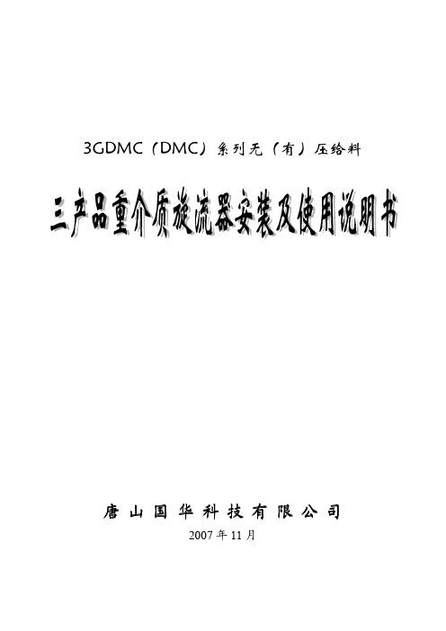
表 3 3GMDC 型三产品重介质旋流器外形尺寸
型 500/35 600/40 700/50 780/55 850/60 920/65 1000/70 1100/78 1200/85 1300/92 1400/100 1500/110
2. 结构特征及工作原理 2.1 结构特征 由一段圆筒形和二段圆筒—圆锥形旋流器串联而成。若原料煤和合格
介质悬浮液预先混合后一起由泵打入一段旋流器,则称 3DMC 型有压给料 三产品重介质旋流器;若原料煤与合格悬浮液分开,单独依靠自重(位能) 由一段旋流器顶部中心处进入,则称 3GDMC 型无压给料三产品重介质旋 流器,其结构示意分别见图 1 和图 2。
3GDMC(DMC)系列无(有)压给料
唐山国华科技有限公司
2007 年 11 月
1. 概述 1.1 特点 依据国家知识产权局授权的《用于选煤的三产品重介质旋流器》(专利
号 ZL03261950.2)并按 Q/GH01-2007 企业标准生产的 3GDMC(DMC)系 列无(有)压给料三产品重介质旋流器,已在全国 200 多座选煤厂被采用, 总处理能力超过 200Mt/a。其特点为:a)能以单一低密度悬浮液一次分选 出质量合格的精煤、中煤和矸石三种产品;b)分选精度高,当入选不分级 不脱泥≤110mm 原煤时,一段可能偏差 E1=0.020~0.030kg/L,二段可能偏 差 E2=0.035~0.050kg/L;c)3GDMC 系列无压给料三产品重介质旋流器入 选原料煤采用与重介质悬浮液分开进入旋流器的方式,能提高分选精度、 节省电耗、减少矸石泥化和次生煤泥量并有利于工艺设备的合理布局;d) 采用外置式二段旋流器分选密度在线调节装置,操作方便、灵活;e)本身 无运动部件,其内衬采用刚玉材料,主体寿命超过 7000h,一般可在最佳工 况条件下工作两年。
DMS配件预测系统操作培训手册

SGM Information System Confidential
Page 17
DIMS 功能介绍
November 10, 2019
SGM Information System Confidential
Page 18
总体流程介绍
Novion System Confidential
那么可以计算出下周的预测销量是: 8+0.2(9-8)=8.2
November 10, 2019
SGM Information System Confidential
Page 12
预测——时间序列
时间序列:
研究预测目标与时间过程的演变关系,根据统计规律性构造拟合X (t)的最佳数学模型,浓缩时间序列信息,简化时间序列的表示,并用 最佳数学模型进行未来预测的方法。
2、系统自动运行生成待补货清单处理时间:
订单上报日前日14:00——14:10
注意:该段时间,请务必保证ASC端服务器正常运行,如 果未按时生成待补货清单,过时请点击待补货清单管理页面中的 “同步拟补货”功能按钮,否则待补货清单不能转订单上报!
3、系统自动运行生成建议紧急订货配件列表时间:
每日0:30——0:40分
季节性:
某些零件需求和季节相关。如果有大于12个月的历史数据,那么对 于这种类型的零件预测比较精准。
November 10, 2019
SGM Information System Confidential
Page 13
库存管理3——库存优化
库存优化:
根据第一步中的零件分类,对零件划分不同优先级别,需求越频繁, 优先级别越高;结合第二步中的预测结果,最终确定该备货零件的种类 以及对应零件的数量。
机床手册-补充部分-DMC64V

我们希望您能够顺利正确地操作 DECKEL MAHO 机床。 此致
DECKEL MAHO Geretsried 股份有限公司
机床的最终用途
基础:
规定 DECKEL MAHO DMC 系列加工中心最终用途。
您购买的 DECKEL MAHO 加工中心采用最新技术制造并符合所有公认 的安全法规、标准和技术规格。
1-5
工作范围
键锁开关
位置 0 位置 1 位置 2 位置 3 参见西门子控制装置手册
轴移动长度
所示所有值均为公里
轴1 轴2 轴3 轴4 轴5 轴6 轴7 轴8 轴9 轴 10 轴 11 轴 12
半熟练操作者 熟练操作者 特别胜任工作的操作者 编程员,机床调整工
X轴 Y1 轴 Z轴 A1 轴 刀库 1 主轴 Y2 轴 A2 轴 刀库 2 未指定 未指定 未指定
用户数据
关闭开关
液压油压力设置 重刀具 门打开时使用润滑冷却剂 无人加工 用自动程序选择交换托盘
关闭开关(“省电”)通/断 在静止 20 分钟后机床驱动自动断开。 该功能具有等同紧急停止的效应。 在重新起动机床之前断开关闭开关。
激活液压工件夹紧 减速旋转运行转盘式刀库 工作区门打开时供应润滑冷却剂 (低压)通/断 无人看管运行通/断 自动程序选择托盘交换通/断
机床的操作可涉及不可预见的危险, 包括:
人员生命和四肢危险; 机床和公司或用户其他资产损坏的危险。
环境,水 源保护
本手册中所述的机床是一种生产、加工和可能使用水污染物质的设备。
这意味着无论何时操作、关闭或拆卸机床或其任何部件时,都必须遵守 用户所在国水资源保护或类似立法方面的法律和法规要求。详细资讯见 管辖可能使用水污染物质的适用国家或地方法规。
日立DMC门板自制说明

DMC、DMD 门机控制简介其中信号输入、输出的主控电子板是DMC 板。
DMC 电子板上的接线端子(WAGO)、指示灯和开关位置如下:DMC电子板DMD 电子板板上部分指示灯和功能设定开关的功能说明如下:DMC板上的指示灯、开关说明指示灯说明L1亮表示有开门信号输入;L2亮表示有关门信号输入;L3亮表示有平层信号输入;L4亮表示有自学习信号输入;L5灭表示有开门极限信号输入;L6灭表示有安全触板信号输入;L7灭表示有关门极限信号输入;L8亮表示有直流24V输入;L9亮表示有直流5V输入;L10~L15亮表示有电机三相控制波形信号输出;L16亮表示有故障信号输出;L17亮表示有门宽测试信号输出(进入门宽测试状态);L18亮表示有ORS信号输出;L19亮表示有屏蔽触板信号输出;L20~21在门低速运动时闪动表示有编码器信号输入;L22亮表示有光电(光幕)信号输入。
开关/跳线说明SW2:微机复位键(自复位开关);SW1:门宽测试键(自锁型开关);JS1:程序选择(跳线);JS2:门速度选择(跳线)。
DMD板上的指示灯说明LED1亮表示有直流5V输入;LED2亮表示有直流155V电压。
控制柜内部主要部件的名称和功能3.3继电器RYBD板元件布置图各发光二极管意义如下。
其它元件参见继电器板原理图和装配图(1)电梯在开门区;(2)关门;(3)开门;(4)门机电源通电;(5)主门触板信号;(6)主门关门极限;(7)主门开门极限;(8)主门光电保护状态;(9)厅门门锁信号(10)轿门门锁;(11)副门触板信号;(12)副门关门极限;(13)副门开门极限(14)副门光电保护状态;(15)非检修状态;(16)轿内/轿顶检修;(17)微动上行;(18)微动下行;(19)微动判断常见说明:。
标准件手册

(11A)标准件(11B)标准件说明本《标准件手册》为《标准手册》的一个重要组成部分。
目前,标准件清单尚不完善,我们会不懈努力,使之处于不断完善之中,包括优选清单。
希望工程师们在以后的设计中尽可能选用清单中已有的标准件,特别是已注明为优选的标准件。
对采用新的标准件或不是优选的标准件标准化中心将会进行严格审查,并给出建议。
本《标准件手册》为动态文件(包括目录),将会有专人进行维护,并定期更新发布,同时所有文件均有电子文档,准确的信息以电子文档为准,可随时向标准化中心(或各部门标准化专员)查询。
标准化中心2002年2月(11C)目录(11) 标准件总清单 (4)(1101) 螺钉类清单 (4)(110101) 十字槽盘头螺钉清单 (4)(110102) 十字槽盘头自攻螺钉清单 (4)(110103) 十字槽沉头自攻螺钉清单 (6)(110104) 圆头类螺钉清单 (6)(110105) 六角类螺钉清单 (7)(110106) 非标类及其他螺钉清单 .......................................... 错误!未定义书签。
(1102) 螺栓类清单(压缩机安装螺钉除外)................................ 错误!未定义书签。
(1103) 螺母类清单 (7)(1104) 垫圈类清单 (8)(1105) 其它类标准件清单 (9)(1106) 常用标准件优选表 (9)(11)标准件总清单(1101)螺钉类清单(110101)十字槽盘头螺钉清单(110102)十字槽盘头自攻螺钉清单(110103)十字槽沉头自攻螺钉清单(110104)圆头类螺钉清单(110105)六角类螺钉清单(1102)螺母类清单(1103)垫圈类清单(1104)其它类标准件清单(1105)常用标准件优选表。
azbil 模件型調節器 DMC10S,DMC10D 使用說明書
CP-UM-5126C模件型調節器 DMC10S,DMC10D 使用說明書注意・本機在安裝、拆除及配線作業時,務必在切斷供給電源後進 行。
否則會產生故障。
・請勿分解本機。
否則會產生故障。
・請在規格記載的使用條件(溫度、濕度、振動、衝撃、安裝 方向、環境等)範圍內使用本機。
否則有發生火災、故障的危險。
・請勿堵塞本機的通風孔。
否則有發生火災、故障的危險。
・請按照本機連線的標準、指定電源及施工方法,正確配線。
否則會有觸電、發生火災、故障的危險。
・請勿讓斷線頭、鐵粉、水等進入機箱內。
否則有發生火災、故障的危險。
・請按規格書中記載的扭矩擰緊端子螺釘。
端子螺釘沒有擰緊時有觸電、發生火災的危險。
・請勿把本機中未使用的端子作爲中繼端子使用。
否則有發生火災・故障的危險。
・有發生雷電湧危險的場合,請使用本公司生産的電湧吸收器。
否則有發生火災・故障的危險。
・廃棄本機時,請按各地方法規及條例,按工業廃棄物進行恰 當處理。
・請在本機的繼電器規格中記載的壽命範圍內使用繼電器。
超過壽命範圍繼續使用時,有發生火災、故障的危險。
・在電源投入後,約10秒鐘內本機不動作。
把本機的繼電器 輸出作為聯鎖信號使用的場合請注意。
・連接的模件全體的消耗功率之和請勿超過100W。
否則有發生火災、故障的危險。
・對連接的模件全體,請勿進行2系統以上的電源供給。
否則會發生火災、故障。
・請勿對控制輸出部(電壓脈衝輸出時) 短路。
短路時,內部 電源的過電流保護產生動作,本機變為復位狀態。
非常感謝您購買模件型調節器DMC10S,DMC10D。
本書只對使用上的注意事項、規格及接線進行説明。
詳細使用方法、設定方法請參閱另冊的模件型調節器 DMC10使用說明書「功能說明篇」 CP-UM-5143C,並正 確使用。
使用上的限制本産品是在一般設備上使用的前提下開發、設計和製 造的。
在有下列安全性要求的場合使用時,請在周全考慮了 失效安全設計、冗餘設計、定期維護檢查等系統和設 備整體的安全性的情況下使用。
DMC-5操作须知

DMC-5遇险信息控制器操作程序1 开关机:1.1按【POWER】键,开机。
1.2按住【POWER】键大约2秒钟,直到听到一响鸣,关机。
2 遇险呼叫步骤2.1 打开【DISTRESS】键盖,按住【DISTRESS】键4秒钟,键灯闪烁,直至常亮开始发射遇险信息。
2.2发布遇险类型1)按住【DISTRESS】键,并在3秒钟之内按相应的数字“【0】-【8】”、“【FILE】”或“【SET UP】”键。
【1】火灾,爆炸;【2】进水;【3】碰撞;【4】搁浅;【5】倾斜,倾覆;【6】下沉;【7】失控和漂航;【8】弃船;【0】不明原因【FILE】人员落水【SET UP】海盗袭击2)按住【DISTRESS】键4秒钟,键灯闪烁接着常亮,开始发射遇险信息。
3 当得到海岸电台确认后,你将看到显示“*RECEIVED* DISTRESSACK”并有声音报警。
(注意接收到确认信息的设备类型,“VHF”:VHF;“MF/HF”:SSB)4 按【3(ALARM RST)】键消除报警音。
5 开始在收到确认信息的无线电设备上进行呼叫。
6 手动输入船位:当无自动船位输入,显示屏出现“Pos:NG”时,按【SET UP】键,手动输入船位数据,按【SELECT】键,选择输入项目,最后按【ENTER】确认。
注意事项:1)保持所有相关无线电设备处于开机状态,以确保能立即进行遇险发射。
2)如果DMC-5接收到遇险报警,遇险或紧急信息或2182kHz报警,【DISTRESS】键灯亮并发出声音报警,按【3(ALARM RST)】键消除报警音,勿按【DISTRESS】键消音。
3)如果意外按了【DISTRESS】键,在5秒钟之内按【CANCEL】键取消遇险报警。
(在按【DISTRESS】键5秒钟之后,遇险报警将不能被消除)4)如果你认为遇险报警可能被意外发射,关闭DMC-5并立即电话通知最近的搜救协调中心。
- 1、下载文档前请自行甄别文档内容的完整性,平台不提供额外的编辑、内容补充、找答案等附加服务。
- 2、"仅部分预览"的文档,不可在线预览部分如存在完整性等问题,可反馈申请退款(可完整预览的文档不适用该条件!)。
- 3、如文档侵犯您的权益,请联系客服反馈,我们会尽快为您处理(人工客服工作时间:9:00-18:30)。
2015-5-9 版本:ZY1.0 梓亿标准件手册梓亿精密模具有限公司前言随着冲压模具技术的不断发展,冲压模具自动化和模具标准化程度越来越高,与国内外同行的交流越来越频繁,新结构的不断出现,使我们原来所用的冲模标准件手册已不能适应新的要求。
为此,我们组织编写了《DMC标准件手册》,作为企业内部标准,供广大技术人员使用。
本标准是在消化吸收国内外模具行业标准的基础上,结合东风汽车模具有限公司实际情况而修订的。
本手册共分九部分:第一部分为一般元件、第二部分为拉延模用标准件、第三部分为弹性元件、第四部分为冲切模用标准件、第五部分为废料处理标准件、第六部分为举升机构标准件、第七部分为大梁模用标准件、第八部分为斜楔相关零件、第九部分为其它专用标准件。
本标准由唐薇、于官树编辑整理,胡海、何奇志校对,甘中明审批。
本标准在编写过程中,得到了国内外同行的大力支持和帮助,在此表示衷心感谢!DMC为东风汽车模具有限公司(DONGFENG MOTOR DIE & MOULD CO.LTD)缩写。
DMC标准件主要参考:MISUMI(三住)、KPS(日产 NISSAN)、QM(汽车冲模标准汇编)。
由于时间和水平的原因,本标准难免存在一些问题,欢迎大家及时指正。
编者:杨勇二零一五年五月25QC02-03-04目录1.一般元件2.拉延模用标准件3.弹性元件4.冲切模用标准件5.废料处理标准件6.举升机构标准件7.大梁模用标准件8.斜楔相关零件9.其它专用标准件SZ PSA铸入式起重棒DMC1110(P1-1)铸入式螺纹套吊耳结构DMC1130(P1- 3)起重棒合件DMC1140(P1- 4)起重棒合件DMC1150(P1- 5) DMC1120(P1- 2)SZ GB SZ SZ SZ吊钩起吊环DMC1165(P1- 7)吊钩(板型)DMC1170(P1- 8)吊钩(板型.头部加大)DMC1180(P1- 9)埋入型吊钩DMC1190(P1- 10)DMC1160(P1- 6)SZ SZ SZ SZ SZ导柱导套DMC1210(P1- 11, 12)DMC1220(P1- 13)自润滑导板DMC1230(P1- 14)自润滑导板 ( H=10)DMC1235(P1- 15)导板垫片DMC1240(P1- 16)QM QM SZ自润滑导板DMC1245(P1- 17)自润滑导板DMC1250(P1- 18)导柱DMC1255(P1- 19)导套DMC1260(P1- 20)导套固定板DMC1270(P1- 21)SZ SZ SZ KPS SZ自润滑外导板导板DMC1275(P1- 22)行程限位块DMC1320(P1- 23)限位块DMC1330(P1- 24)缓冲器DMC1340(P1- 25)聚氨酯缓冲合件DMC1350(P1- 26)SZ聚氨酯缓冲合件SZ SZ限位块DMC1360(P1- 28)连接板DMC1370(1- 29)侧销合件DMC1410- 1420侧销合件DMC1410(P1- 30)DMC1350(P1- 27)SZ SZ SZSZ SZ侧销合件DMC1420(P1- 31)卸料螺栓DMC1430(P1- 32)行程限位螺栓DMC1440(P1- 33)卸料定位销DMC1450(P1- 34)卸料定位销用行程调整环DMC1460(P1- 35)镶块靠背用SZ KPS QMSZ定位键DMC1510(P1- 36)键DMC1520(P1- 37)键DMC1525(P1- 38)楔形键DMC1530(P1- 39)顶销DMC1610(P1- 40)QM QM QM QM SZ推销DMC1620(P1- 41)托杆DMC1630(P1- 42)麻点托杆DMC1635(P1- 43)带肩推杆DMC1640(P1- 44)定位销DMC1710(P1- 45)SZ定位导正销DMC1720(P1- 46)模具快速定位销DMC1730(P1- 47)模具铭牌DMC1810(P1- 48)模具铭牌DMC1820(P1- 49)托杆铭牌DMC1830(P1- 50)QM SZ SZ SZ SZ滚轮挡料块DMC2110(P2- 1)电检测挡料块DMC2120(P2- 2)挡料块DMC2130(P2- 3)左/右挡料板DMC2135(P2- 4)挡料块DMC2140(P2- 5)QM QM圆棒托料架合件DMC2145(P2- 6)滚道托料架合件DMC2150(P2- 7)滚道托料架合件DMC2160(P2- 8)滚道合件DMC2170(P2- 9)滚道DMC2171(P2- 10)QM QM滚轮DMC2172(P2- 11)销轴DMC2173(P2- 12)圆形滑料托架合件DMC2180(P2- 13)方形滑料托架合件DMC2190(P2- 14)滚轮合件DMC2210(P2- 15)滚轮挡料块DMC2220(P2- 16)滚轮DMC2221(P2- 17)销轴DMC2222(P2- 18)座合件DMC2223(P2- 19)滚轮座DMC2224(P2- 20)SZ KPS SZ SZ SZ通气孔DMC2310(P2- 21)CH孔合件DMC2410(P2- 22)圆形垫块DMC2510(P2- 23)方形垫块DMC2520(P2- 24)平衡块DMC2530(P2- 25)SZ SZ PSA PSA PSA圆形垫片DMC2540(P2- 26)方形垫片DMC2550(P2- 27)压字合件DMC2610(P2- 28)压字凸模DMC2620(P2- 29)压印凸模DMC2630(P2- 30)QM SZ SZ压印器DMC2640(P2- 31)压字凸模DMC2650(P2- 32)压字凸模DMC2660(P2- 33)压印凸模DMC2670(P2- 34)压印凸模DMC2680(P2- 35)3.弹性元件SZ SZ SZ SZSZ氮气弹簧合件DMC3110(P3- 1)氮气弹簧合件DMC3120(P3- 2)氮气弹簧DMC3130(P3- 3)氮气弹簧DMC3140(P3- 4)安装板DMC3150(P3- 5)凸模SZ QM QM QM QM安装板DMC3160(P3- 6)聚胺酯橡胶弹簧DMC3210(P3- 7)聚胺酯橡胶弹簧DMC3220(P3- 8)弹簧定位销DMC3310(P3- 9)弹簧定位销DMC3320(P3- 10)QM QM BT BT氮气弹簧配置图BT圆钢丝弹簧DMC3410(P3- 11)扁钢丝弹簧DMC3420(P3- 12)控制板氮气弹簧N型DMC3510(P3- 13)DMC3520(P3- 14. 15)DMC3610(P3-16)BT BT氮气弹簧NF型DMC3620(P3- 17)氮气弹簧NC型DMC3630(P3- 18)4.冲切模用标准件SZ SZ SZ SZ SZ肩型凸模DMC4110(P4- 1)肩型凸模(短型 )DMC4120(P4- 2)肩型凸模(长型 )DMC4130(P4- 3)球锁紧凸模DMC4140(P4- 4)翻边凸模DMC4150(P4- 5)SZ SZ SZ SZ SZ厚板冲裁用凸模DMC4160(P4- 6)凸模压块DMC4310(P4- 7)固定块合件DMC4320(P4- 8)球琐紧固定块DMC4330(P4- 9)方形固定块合件DMC4340(P4- 10)SZ SZSZ SZ PC凹模DMC4510(P4- 11)凹模DMC4520(P4- 12)凹模DMC4530(P4- 13)球锁紧凹模DMC4540(P4- 14)凹模DMC4550(P4- 15)SZ SZ SZ肩型凹模用支撑环DMC4560(P4- 16)防转键DMC4570(P4- 17)滚道合件DMC4610(P4- 18)托料臂DMC4620(P4- 19)送料托架合件DMC4630(P4- 20)KPS SZ PSA PSA PSA顶出器衬套DMC4710(P4- 21)导料轮合件DMC4720(P4- 22)初加工快换冲头DMC4810(P4- 23)初加工快换冲头DMC4820(P4- 24)初加工快换冲头DMC4830(P4- 25)5.废料处理KPS废料盒合件DMC5110(P5- 1)废料挡销DMC5120(P5- 2)废料槽盖板合件DMC5130(P5- 3)废料盒合件DMC5140(P5- 4)废料盒合件DMC5150(P5- 5)废料滑板合件DMC5160(P5- 6)链合件DMC5170(P5- 7)SZ SZ SZ SZ SZ气缸顶料合件DMC6110(P6- 1, 2)气缸DMC6120(P6- 3)顶料缓冲器DMC6130(P6- 4)折边顶料器DMC6140(P6- 5, 6)顶料块DMC6150(P6- 7)SZ SZ SZ SZSZ顶料先行销DMC6160(P6- 8)挡料板DMC6170(P6- 9)定位块DMC6180(P6- 10)侧定位块DMC6190(P6- 11)弹簧顶销DMC6210(P6- 12)BSM JD JD JD JD单活塞杆双作用小型缓冲气动提升器DMC6220(P6- 13)前端固定式气缸DMC6520(P6- 15)头部销轴摆动式气缸尾部轴销摆动式气缸DMC6530(P6- 16) DMC6540(P6- 17)气缸DMC6510(P6- 14)JD JD JD JD前法兰式气缸DMC6545(P6- 18)单活塞杆标准气缸DMC6550(P6- 19)前法兰式气缸DMC6560(P6- 20)后法兰式气缸DMC6570(P6- 21)尾部单耳式气缸DMC6580(P6- 22)JD JD JD JDJD尾部双耳式气缸DMC6590(P6- 23)脚架式气缸DMC6610(P6- 24)卡管式直通终端管接头DMC6810(P6- 25)卡管式直通管接头DMC6820(P6- 26)卡管式三通终端管接头DMC6830(P6- 27)JD JDNPK 卡管式三通管接头 DMC6840(P6- 28) 卡管式直角终端管接头 DMC6850(P6- 29) 快插式直通管接头 DMC6860(P6- 30) 气缸配置图 DMC6910(P6- 31) 气缸配置图 DMC6920(P6- 32)气缸配置图 DMC6930(P6- 33) 气缸配置图DMC6940(P6- 34)7.大梁模用标准件导销DMC7110(P7- 1)推杆DMC7120(P7- 2)打杆DMC7130(P7- 3)定位销DMC7140(P7- 4)顶销DMC7150(P7- 5)导正销固定板DMC7160(P7- 6)铸入式起重棒DMC7170(P7-7)连接杆DMC7180(P7- 8)定位销合件DMC7190(P7- 9)导正销DMC7210(P7- 10)凸模DMC7220(P7- 11)凹模DMC7230(P7- 12)8.斜楔相关零件SZ SZ SZ SZ SZ斜楔用滑板DMC8110(P8- 1)斜楔侧挡板DMC8120(P8- 2)斜楔上挡板DMC8130(P8- 3)斜楔侧挡板DMC8140(P8- 4)斜楔镶板(30°)DMC8150(P8- 5)SZ SZ SZ SZ SZ斜楔镶板(15°) DMC8160(P8- 6)斜楔下导向板DMC8170(P8- 7)斜楔下滑板DMC8180(P8- 8)斜楔强制复位块DMC8210(P8- 9)斜楔强制复位块DMC8220(P8- 10)SZ SZ斜楔限位块斜楔复位用部件DMC8230(P8- 11)DMC8240(P8- 12, 13)9.其它专用标准件锁板DMC9110(P9- 1)。
